ATOP Technologies AT705RFID Picktag User Manual AT707A4KRF USER MANAUAL
ATOP Technologies, INC. Picktag AT707A4KRF USER MANAUAL
UserManual.wiki
>
ATOP Technologies
>
AT705RFID User Manual
>
User Manual (AT707A4KRF)
Contents
1.
User Manual (AT707A4KRF)
2.
User Manual (AT7053KRF)
3.
User Manual (AT705233KRF)
User Manual (AT707A4KRF)
Navigation menu
Upload a User Manual
Namespaces
Wiki Guide
HTML
PDF
Info
Views
User Manual
Discussion / Help
Navigation

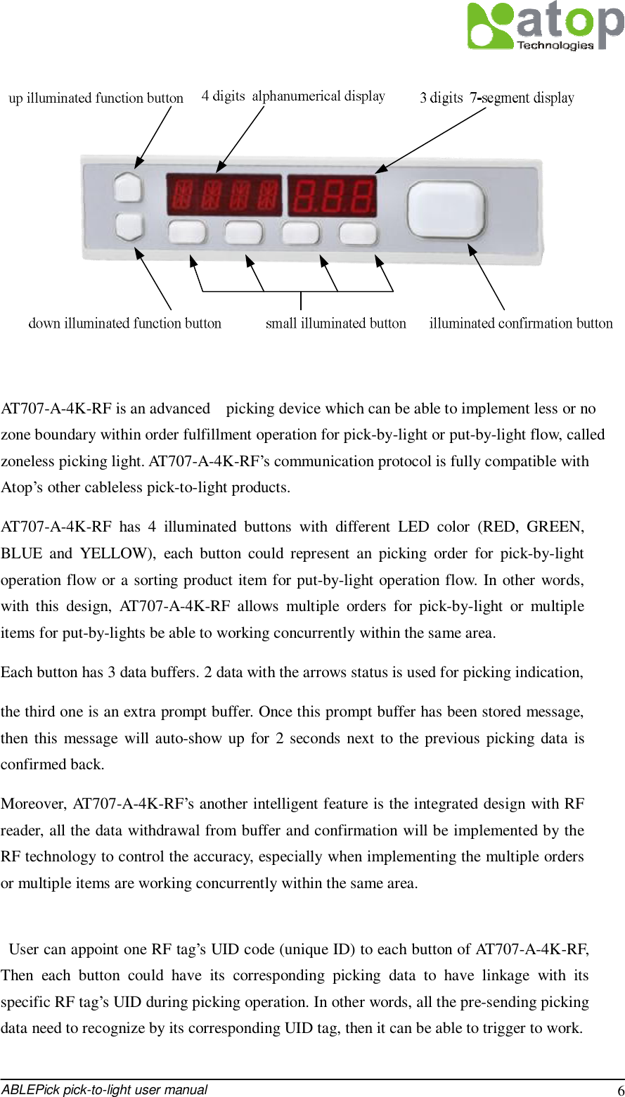
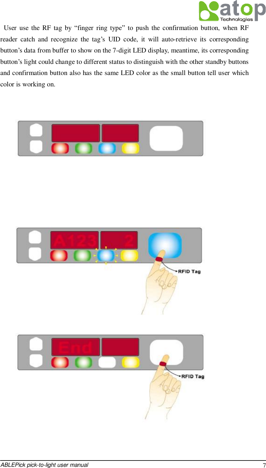

![ABLEPick pick-to-light user manual 9 Step3: The confirmation button’s LED light will change color: RED, GREEN , BLUE sequently. Step4: Show the F/W version of the tag. For example: “U1.0”. Step5: Show the address ID of the tag. For example: “[001]” (this is a decimal number). Step6: Show the tag mode configuration of the tag. The default tag mode configuration value is 115. in decimal. Address configuration via the buttons directly. The same as the other light model with three buttons Self-test function enabled The same as the other light model with three buttons AT707-A-4K-RDIF hardware Specification 1) Has two pairs of magnetic connectors to connect easily to main transmission bus with stainless stuff. Two pairs of connectors are the redundancy design to enforce the connection 2) 7-digits LED display. The first 4 digits are alphanumerical display, the left 3 digits are 7-segment display. 3) 2 up/down illuminated function buttons. Both Up and Down arrow buttons are WHITE color. 4) One large illuminated confirmation button with 6-color LED. 5) 4 small illuminated button with different LED color by RED, GREEN, BLUE and YELLOW from left to right. . 6) Each small illuminated button has 3 corresponding data buffer. 2 is for picking data, another extra is called prompt buffer. It will be displayed automatically hereon the picking data when it has been stored in.](https://usermanual.wiki/ATOP-Technologies/AT705RFID.User-Manual-AT707A4KRF/User-Guide-1673667-Page-10.png)