Casi Rusco 1000-1010 1000/1010 Access Control Reader User Manual 00 cover
Casi Rusco 1000/1010 Access Control Reader 00 cover
Installation guide

Draft
Part Number: 460350002D2
June 2000
Model 1000/1010
Dual Tech
(Proximity/
Magnetic Stripe)
Reader
Installation Guide
CASI
RUSCO
A FIGGIE INTERNATIONAL
COMPANY
791 Park of Commerce Boulevard
Boca Raton, Florida 33487
(561) 998-6100
CASI-RUSCO...Security Solutions for the 21st Century

This publication may contain examples of data reports used in daily
business operations. Examples include fictitious names of individuals
and companies for illustration only; any similarity to names and
addresses of actual business enterprises and persons is entirely
coincidental.
This document is distributed on an as is basis, without warranty either
expressed or implied. Successful implementation depends solely upon
the customer’s ability to integrate each product into the total inventory
of “in-house” products. While each offering has been reviewed for its
compatibility and maintainability, no assurance of successful
installation can be given.
The customer accepts full maintenance responsibility. (A full scope of
software and hardware maintenance contracts are available to the
customer.)
Copyright 1998 - 2000 CASI-RUSCO
All Rights Reserved.
Printed in the USA.
ProxLite and Proximity Perfect are trademarks of CASI-RUSCO.
WARNING
This is a Class A product. In a domestic environment, this product
may cause radio interference, in which case, the user may be required
to take adequate measures.
Model 1000/1010 Dual Tech (Prox/MagStripe) Reader i
Contents
Introduction ....................................................................................................... 1
Product Features ............................................................................................... 2
Installation Overview ....................................................................................... 3
Mounting the Reader........................................................................................ 4
Setting Switches............................................................................................... 13
Supervised/Unsupervised ...............................................................13
Fixed Frequency................................................................................. 13
Door Strike Relay Output................................................................. 14
Beeper Sound Level...........................................................................14
Power Setting .....................................................................................14
Connecting the Reader ................................................................................... 16
FCC Compliance ................................................................................16
FCC Rules ........................................................................................... 16
Pinouts................................................................................................. 18
Wiring Diagrams ............................................................................... 20
Testing the Reader .......................................................................................... 30
Troubleshooting the Reader .......................................................................... 32
Technical Specifications ................................................................................. 37
Functional Specifications ............................................................................... 38
ii
Model 1000/1010 Dual Tech (Prox/MagStripe) Reader
Figures
Figure 1: Backplate Preparation .................................................... 6
Figure 2: Model 1000/1010 Reader Dual Gang Box Moun ting ..... 7
Figure 3: Model 1000/1010 Reader, Dual Gang Box Mounting,
Continued....................................................................... 8
Figure 4: Model 1000/1010 Reader, Direct Wall Mounting ........... 9
Figure 5: Model 1000/1010 Reader, Surface Mount Box ............ 10
Figure 6: Model 1000/1010 Reader, Surface Mount Box,
Continued ..................................................................... 11
Figure 7: Model 1000/1010 Reader, 5029 Back Box or
Environmental Hood Mounting ..................................... 12
Figure 8: Model 1000/1010 Reader, Jumper Setting .................. 15
Figure 9: Typical Installation Using Shielded Cable/Drain Wire .. 16
Figure 10: Wiring Diagram for 12V Operation, Model 1000/1010
Reader to Door Strike and Microcontroller (Connection to
J13 DB9) 20
Figure 11: Wiring Diagram for 48V Operation, Model 1000/1010
Reader to Door Strike and Microcontroller (Connection to
J13 DB9) 22
Figure 12: Wiring Diagram for 12V Operation, Model 1000/1010
Reader to Door Strike and Microcontroller (Connection to
J8 11-Pin Phoenix - Unsupervised DI) ......................... 24
Figure 13: Wiring Diagram for 12V Operation, Model 1000/1010
Reader to Door Strike and Microcontroller (Connection to
J8 11-Pin Phoenix - Supervised DI 26
Figure 14: Wiring Diagram for 48V Operation, Model 1000/1010
Reader to Door Strike and Microcontroller (Connection to
J8 11-Pin Phoenix) ....................................................... 28
Figure 15: Badge to Reader Presentation ..................................... 38
Model 1000/1010 Dual Tech (Prox/MagStripe) Reader 1
Introduction
This manual is an installation guide for the CASI-RUSCO Model
1000/1010 Dual Tech (Prox/Magstripe) Reader.
The Models 1000 and 1010 Readers are identical in their functionality,
except that the Model 1010 includes an integrated keypad used for the
entry of a personal identification number (PIN).
The reader communicates with the microcontroller through a
bidirectional data link which carries:
•Keypad data (Model 1010 only).
•Magnetic stripe data and/or Proximity card data.
•Command responses.
•Exit request switch and door status switch messages.
•Supervision messages.
IBM Model 5029 Reader Compatibility:
•The reader replaces the IBM Model 5029 Reader physically and
operationally.
•The wiring and connection to the reader is identical to that of the
Model 5029 Reader.
•The reader sends magnetic stripe data and/or proximity card data to
the microcontroller.
•You can replace an existing Model 5029 Reader without any changes
to the equipment to which it is connected. Simply unplug an existing
Model 5029 Reader and plug in the Model 1000 or 1010 Reader.
•The reader contains a jumper-selectable option for silent supervision.
2Model 1000/1010 Dual Tech (Prox/MagStripe) Reader
Product Features
The CASI-RUSCO Models 1000 and 1010 Dual Tech Readers offer:
•State-of-the-art architecture.
•Communication between the reader and microcontroller up to one
mile* over a standard telephone cable.
•Reads ABA track 2 format magnetic stripe cards of any length, up to
the first 16 numeric digits that are sent to the microcontroller.
•Reads ProxLiteTM and Proximity PerfectTM proximity cards.
•A compact, aesthetically pleasing design.
•Weather resistant for outdoor use. **
•Built-in intelligence for communication with the microcontroller.
•12V to 48VDC operation.
•Power-on self test.
•A clear user interface.
•A tactile keypad (Model 1010) for personal identification number
(PIN) entry and LED indicators in the same package.
•Rugged polycarbonate construction.
•A door strike relay for AC or DC operation, selectable normally open
or normally closed contacts.
•Built-in tamper alarm with external option.
•Automatic self-tuning to compensate for component aging and
mounting location.
•Switch-selectable supervised or unsupervised operation.
•Switch-selectable 40-bit Wiegand output.
•Switch-selectable normal 12-digit output or custom 10-digit.
•Switch-selectable door, exit request switch supervision.
* See the reader wiring diagrams section of this manual.
** Although the reader is weather resistant, it is not weatherproof;
therefore, the reader must be mounted out of direct exposure to rain
and/or snow.
Model 1000/1010 Dual Tech (Prox/MagStripe) Reader 3
Installation Overview
The following is the general sequence of steps to follow in installing the
1000/1010 reader. Each step is explained in further detail in the sections
that follow:
1. Prepare the backplate. Refer to Figure1, “Backplate Preparation,” on
page6.
2. Install reader mounting. Refer to “Mounting the Reader” on page4.
3. Set the switches. Refer to “Setting Switches” on page13.
4. Connect the reader. Refer to “Connecting the Reader” on page16.
5. Mount the reader. Refer to “Mounting the Reader” on page4.
6. Test the reader. Refer to “Testing the Reader” on page30.
7. If necessary, refer to “Troubleshooting the Reader” on page32.
4Model 1000/1010 Dual Tech (Prox/MagStripe) Reader
Mounting the Reader
The reader comes with a backplate suitable for mounting directly onto
standard U.S. electrical dual gang boxes. For other mounting
applications, see Figures 2 through 7.
A gasket is supplied with the reader to form a weather-resistant seal
between the backplate and the reader housing. This gasket is used to
make the reader weather resistant, not weatherproof. Mount the reader
out of direct exposure to rain or snow. Order and install the optional Cold
Weather Kit for installations where below-freezing temperatures are
anticipated.
•Readers should be mounted with their centers offset by at least 10
inches to provide interference-free operation.
•If readers are mounted side-by-side within 5 inches of each other,
jumper setting JP7 Shorted needs to be used.
•If readers are mounted back-to-back, use metal mounting plate.
Wiring diagrams are included in this manual. When replacing a Model
5029 with the Model 1000 or 1010, no change of wiring is required when
the existing cable does not exceed one mile and is 20 AWG or larger.
For 12V operation over distances greater than 500 feet or with wire
smaller than 20 AWG, an auxiliary power supply may be required at the
reader. If this situation arises:
1. Disconnect the power supply wire at the reader (J13 pin 7) from the
microcontroller supply and connect a local power supply to this pin.
2. Connect the power supply return to the ground wire (J13 pin 1),
leaving the ground wire to the microcontroller connected.
3. Fold and tape the power wire from the microcontroller to prevent a
short circuit.
The local supply must be able to deliver approximately 250 mA of
regulated direct current at the voltage of choice.
Model 1000/1010 Dual Tech (Prox/MagStripe) Reader 5
There are four different methods of mounting the reader:
1. Dual Gang Box Mounting. Refer to Figure2, “Model 1000/1010
Reader Dual Gang Box Mounting,” on page7 and Figure3, “Model
1000/1010 Reader, Dual Gang Box Mounting, Continued,” on page8.
2. Direct Wall Mounting. Refer to Figure4, “Model 1000/1010 Reader,
Direct Wall Mounting,” on page9.
3. Surface Box Mounting. Refer to Figure5, “Model 1000/1010 Reader,
Surface Mount Box,” on page10 and Figure6, “Model 1000/1010
Reader, Surface Mount Box, Continued,” on page11.
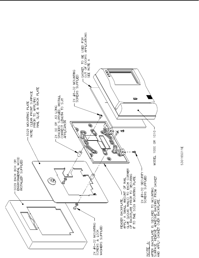
4. 5029 Back Box and Environmental Hood Mounting. Refer to
Figure7, “Model 1000/1010 Reader, 5029 Back Box or Environmental
Hood Mounting,” on page12.
6Model 1000/1010 Dual Tech (Prox/MagStripe) Reader
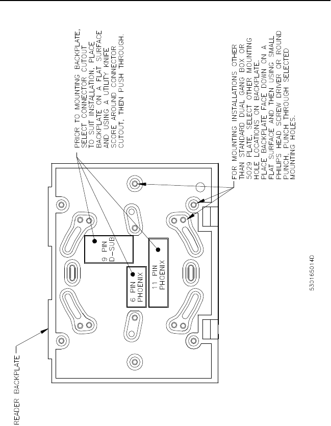
FIGURE 1: Backplate Preparation
Model 1000/1010 Dual Tech (Prox/MagStripe) Reader 7
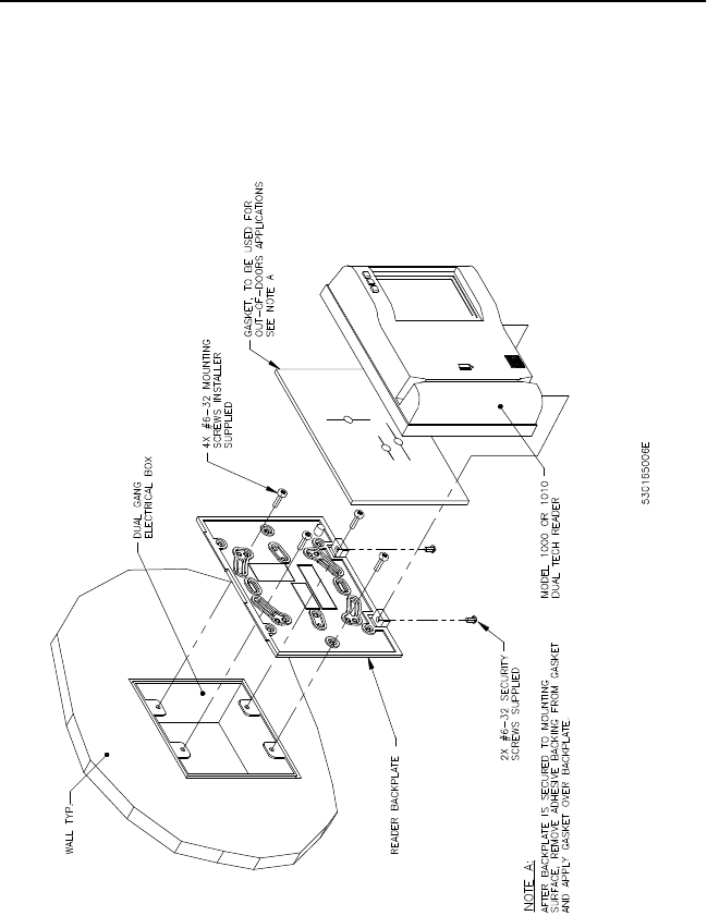
FIGURE 2: Model 1000/1010 Reader Dual Gang Box Mounting
8Model 1000/1010 Dual Tech (Prox/MagStripe) Reader
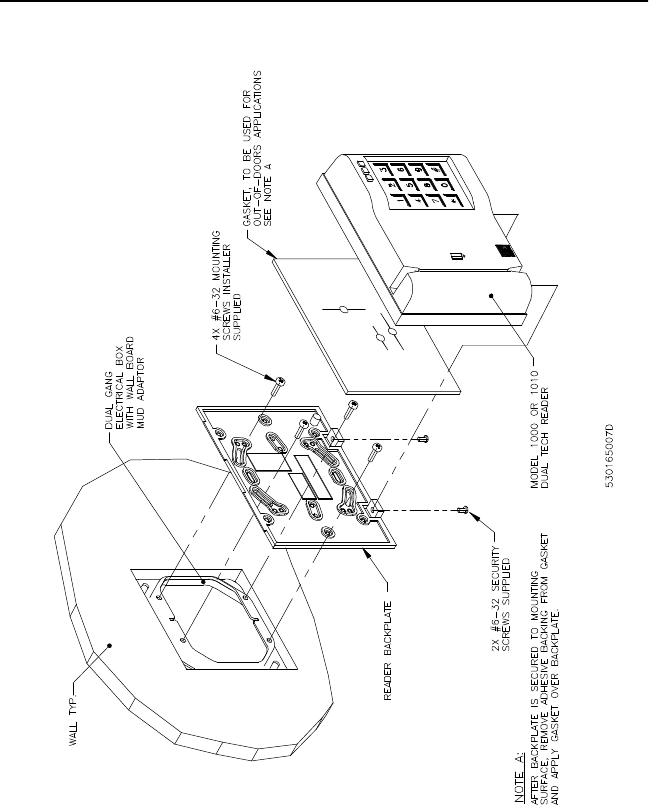
FIGURE 3: Model 1000/1010 Reader, Dual Gang Box Mounting,
Continued
Model 1000/1010 Dual Tech (Prox/MagStripe) Reader 9
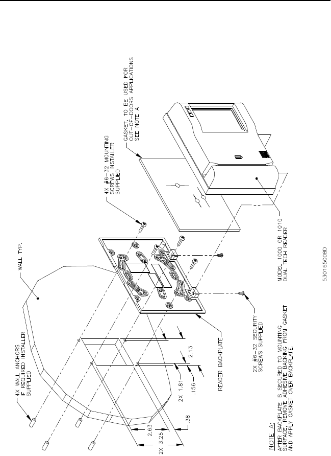
FIGURE 4: Model 1000/1010 Reader, Direct Wall Mounting

10 Model 1000/1010 Dual Tech (Prox/MagStripe) Reader
FIGURE 5: Model 1000/1010 Reader, Surface Mount Box
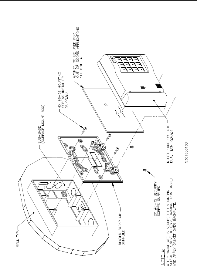
Model 1000/1010 Dual Tech (Prox/MagStripe) Reader 11
FIGURE 6: Model 1000/1010 Reader, Surface Mount Box, Continued
12 Model 1000/1010 Dual Tech (Prox/MagStripe) Reader
FIGURE 7: Model 1000/1010 Reader, 5029 Back Box or
Environmental Hood Mounting

Model 1000/1010 Dual Tech (Prox/MagStripe) Reader 13
Setting Switches
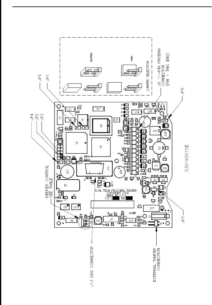
Refer to Figure8 on page 15 for the location of the jumpers.
Supervised/Unsupervised
In the Supervised mode, there is regular communication with the micro.
If communications is lost to the micro, the red LED will give three short,
rapid blinks every few seconds. In the Unsupervised mode, there is no
regular communication with the micro.
Fixed Frequency
NOTE: Fixed frequency may need to be selected when readers are less than
10 inches away from each other and not back-to-back.
TABLE 1: Mode Jumpers
Brand JP1 JP4 JP5
Unsupervised, IBM1
1. DI information is transmitted only in F/2F supervised
mode.
ON ON ON
Supervised, IBM
DIs Unsupervised OFF ON ON
Unsupervised, Generic 1ON OFF ON
Supervised, Generic
DIs Unsupervised OFF OFF ON
Supervised, Generic 2
DIs Supervised
2. 1K resistors need to be installed.
OFF OFF OFF
Wiegand Out, Generic1ON OFF OFF
Wiegand Out, IBM1ON ON OFF
TABLE 2: Fixed Frequency
Power JP7
Self-Tuned Open
Fixed Frequency Shorted

14 Model 1000/1010 Dual Tech (Prox/MagStripe) Reader
Door Strike Relay Output
JP2 - Selects the normally closed contacts for use with fail-safe door
strikes.
JP3 - Selects the normally open contacts for use with fail-secure door
strikes.
Beeper Sound Level
Power Setting
TABLE 3: Door Strike Relay Output
Jumper Jumper Selection Contacts
JP2 Open -
Shorted Normally Closed Selected
JP3 Open -
Shorted Normally Open Selected
TABLE 4: Beeper Sound Levels
Beeper
Sound Level
Switch S2
Position 1 Position 2
Normal ON ON
Low ON OFF
Off OFF OFF
TABLE 5: Power Setting
JP6 Power
Open Normal
Shorted High Power
Model 1000/1010 Dual Tech (Prox/MagStripe) Reader 15
FIGURE 8: Model 1000/1010 Reader, Jumper Setting
16 Model 1000/1010 Dual Tech (Prox/MagStripe) Reader
Connecting the Reader
FCC Compliance
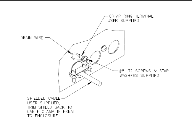
To make the Model 1100/1081 Reader installation FCC compliant, the
following conditions must be met:
•The cable connecting the Model 1100/1081 Reader to the Micro/5
must have its shield grounded at the Micro/5 according to Figure9.
•One ferrite must be placed around each cable inside the bottom panel
of the reader.
FIGURE 9: Typical Installation Using Shielded Cable/Drain Wire
FCC Rules
Information to User
This device complies with Part 15 of the FCC Rules. Operation is subject
to the following two conditions:
1. This device may not cause harmful interference.
2. This device must accept any interference received, including
interference that may cause undesired operation.
This equipment has been tested and found to comply with the limits for
Class B Digital Device, pursuant to Part 15 of the FCC Rules. These limits
Model 1000/1010 Dual Tech (Prox/MagStripe) Reader 17
are designed to provide reasonable protection against harmful
interference in a residential installation. This equipment generates and
can radiate radio frequency energy and, if not installed and used in
accordance with the instructions, may cause harmful interference to radio
communications. However, there is no guarantee that interference will
not occur in a particular installation. If this equipment does cause
harmful interference to radio or television reception, which can be
determined by turning the equipment off and on, the user is encouraged
to try to correct the interference by one or more of the following
measures.
•Reorient or relocate the receiving antenna.
•Increase the separation between the equipment and receiver.
•Connect the equipment into an outlet on a circuit different from that
to which the receiver is connected.
•Consult the dealer or an experienced radio/TV technician for help.
Any changes or modifications not expressly approved by the part
responsible for compliance could void the user’s authority to operate the
equipment.

18 Model 1000/1010 Dual Tech (Prox/MagStripe) Reader
Pinouts
The Model 1000/1010 Reader contains two connectors: a standard 9-pin
D-subminiature connector (DB9) and a phoenix connector. The pinouts
for the DB9 connector are in Table 6 below. The pinouts for the phoenix
connector are in Table 7 on page 19.
NOTE: Signals on the DB9 connector are also available on the phoenix
connector to allow the installer to choose either the DB9 or the 11-pin
phoenix for connecting the reader.
TABLE 6: Pinouts for DB9 Connector J13
Pin # Signal Standard
Color
1Ground Black
2Switch common Orange
3F/2F Red
4Strike relay output Blue
5Exit DI (Exit Request Button) Violet
6Strike relay return White
712 to 48V DC Yellow
8Door DI (Door Contact Switch) Grey
9Door DO input from microcontrollers
(to control the strike relay) Brown

Model 1000/1010 Dual Tech (Prox/MagStripe) Reader 19
TABLE 7: Pinouts for Phoenix Connector J8
Pin # Signal Standard
Color
1Exit Request Return Black
2Door Return Orange
3Door DO input from microcontrollers
(to control the strike relay) Red
4Door DI (Door Contact Switch) Blue
512 to 48V DC Violet
6Strike relay return White
7Wiegand Data 0 Yellow
8Strike relay output Grey
9F/2F or Wiegand Data 1 Brown
10 Exit DI (Exit Request Button)
11 Ground
20 Model 1000/1010 Dual Tech (Prox/MagStripe) Reader
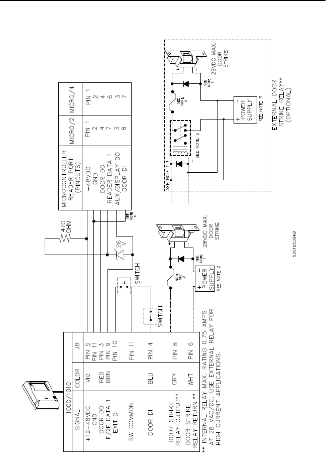
Wiring Diagrams
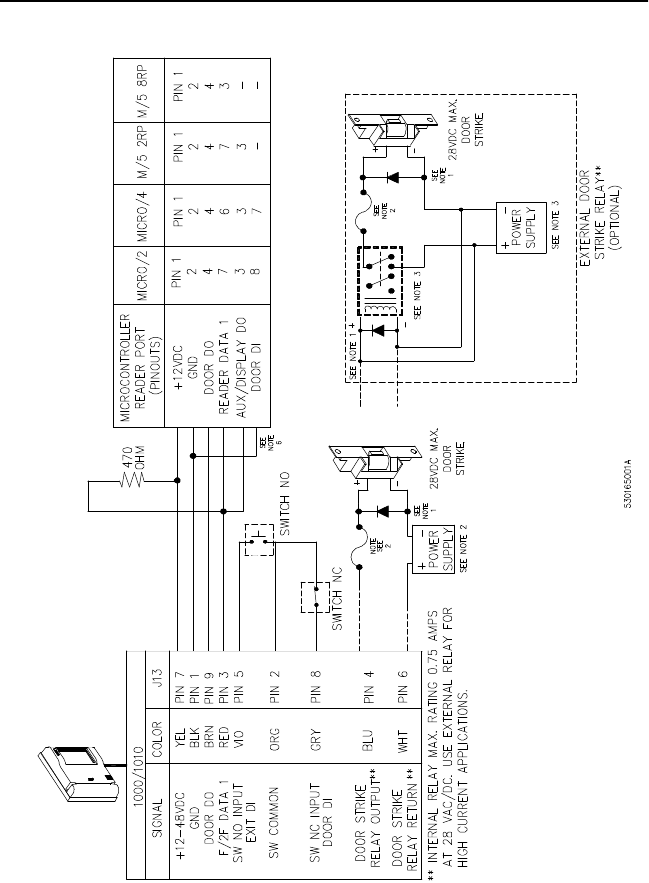
FIGURE 10: Wiring Diagram for 12V Operation, Model 1000/1010
Reader to Door Strike and Microcontroller (Connection to J13 DB9)

Model 1000/1010 Dual Tech (Prox/MagStripe) Reader 21
NOTES: Unless otherwise specified:
1. Protection diodes may be 1N4002, 1N4003, or 1N4004 for the door strike assembly (supplied by the installer) for DC
strikes only.
2. One amp fuse, power supply (fused primary), and relay provided by the installer/customer.
3. Relay coil resistance must be 100 ohms or greater at 12VDC.
4. Maximum cabling distance using 20 AWG telephone wire is 500 feet for 12VDC micros. Shielded cable is
recommended in electrically-noisy environments.
5. If using shielded cable, connect all shields together at the micro end, connect to ground stud in lower left corner of
cabinet using 14 AWG wire. No shield connections at reader.
6. Micro/2 and Micro/4 only: If wiring door DI switch through reader (as shown), door DI on reader board must be
connected to Ground.
22 Model 1000/1010 Dual Tech (Prox/MagStripe) Reader
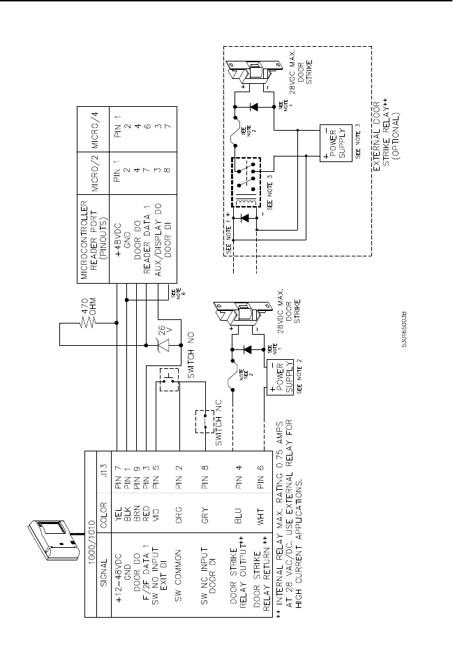
FIGURE 11: Wiring Diagram for 48V Operation, Model 1000/1010
Reader to Door Strike and Microcontroller (Connection to J13 DB9)

Model 1000/1010 Dual Tech (Prox/MagStripe) Reader 23
NOTES: Unless otherwise specified:
1. Protection diodes may be 1N4002, 1N4003, or 1N4004 for the door strike assembly (supplied by the installer) for DC
strikes only.
2. One amp fuse, power supply (fused primary), and relay provided by the installer/customer.
3. Relay coil resistance must be 100 ohms or greater at 48VDC.
4. Maximum cabling distance using 20 AWG telephone wire (shielded) is 6,000 feet for 48VDC micros. The use of
unshielded cable may allow longer distances or similar distances with smaller gauge wire; however, noise
problems may result. Shielded cable is recommended in electrically-noisy environments.
5. If using shielded cable, connect all shields together at the micro end, connect to ground stud in lower left corner of
cabinet using 14 AWG wire. No shield connections at reader.
6. Micro/2 and Micro/4 only: If wiring door DI switch through reader (as shown), door DI on reader board must be
connected to Ground.
24 Model 1000/1010 Dual Tech (Prox/MagStripe) Reader
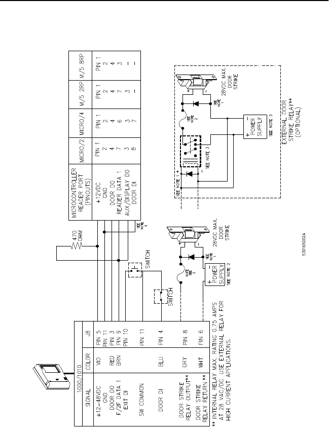
FIGURE 12: Wiring Diagram for 12V Operation, Model 1000/1010
Reader to Door Strike and Microcontroller (Connection to J8 11-Pin
Phoenix - Unsupervised DI)

Model 1000/1010 Dual Tech (Prox/MagStripe) Reader 25
NOTES: Unless otherwise specified:
1. Protection diodes may be 1N4002, 1N4003, or 1N4004 for the door strike assembly (supplied by the installer) for DC
strikes only.
2. One amp fuse, power supply (fused primary), and relay provided by the installer/customer.
3. Relay coil resistance must be 100 ohms or greater at 12VDC.
4. Maximum cabling distance using 20 AWG telephone wire is 500 feet for 12VDC micros. Shielded cable is
recommended in electrically noisy environments.
5. If using shielded cable, connect all shields together at the micro end, connect to ground stud in lower left corner of
cabinet using 14 AWG wire. No shield connections at reader.
6. Micro/2 and Micro/4 only: If wiring door DI switch through reader (as shown), door DI on reader board must be
connected to Ground.
26 Model 1000/1010 Dual Tech (Prox/MagStripe) Reader
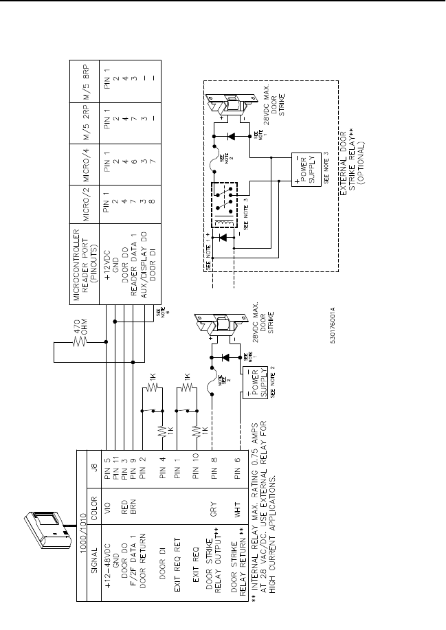
FIGURE 13: Wiring Diagram for 12V Operation, Model 1000/1010
Reader to Door Strike and Microcontroller (Connection to J8 11-Pin
Phoenix - Supervised DI

Model 1000/1010 Dual Tech (Prox/MagStripe) Reader 27
NOTES: Unless otherwise specified:
1. Protection diodes may be 1N4002, 1N4003, or 1N4004 for the door strike assembly (supplied by the
installer) for DC strikes only.
2. One amp fuse, power supply (fused primary), and relay provided by the installer/customer.
3. Relay coil resistance must be 100 ohms or greater at 12VDC.
4. Maximum cabling distance using 20 AWG telephone wire is 500 feet for 12VDC micros. Shielded cable is
recommended in electrically noisy environments.
5. If using shielded cable, connect all shields together at the micro end, connect to ground stud in lower left
corner of cabinet using 14 AWG wire. No shield connections at reader.
6. Micro/2 and Micro/4 only: If wiring door DI switch through reader (as shown), door DI on reader board
must be connected to Ground.
28 Model 1000/1010 Dual Tech (Prox/MagStripe) Reader
FIGURE 14: Wiring Diagram for 48V Operation, Model 1000/1010
Reader to Door Strike and Microcontroller (Connection to J8 11-Pin
Phoenix)

Model 1000/1010 Dual Tech (Prox/MagStripe) Reader 29
NOTES: Unless otherwise specified:
1. Protection diodes may be 1N4002, 1N4003, or 1N4004 for the door strike assembly (supplied by the installer) for DC
strikes only.
2. One amp fuse, power supply (fused primary), and relay provided by the installer/customer.
3. Relay coil resistance must be 100 ohms or greater at 48VDC.
4. Maximum cabling distance using 20 AWG telephone wire (shielded) is 6,000 feet for 48VDC micros. The use of
unshielded cable may allow longer distances or similar distances with smaller gauge wire; however, noise
problems may result. Shielded cable is recommended in electrically-noisy environments.
5. If using shielded cable, connect all shields together at the micro end, connect to ground stud in lower left corner of
cabinet using 14 AWG wire. No shield connections at reader.
6. Micro/2 and Micro/4 only: If wiring door DI switch through reader (as shown), door DI on reader board must be
connected to Ground.
30 Model 1000/1010 Dual Tech (Prox/MagStripe) Reader
Testing the Reader
Perform the following test procedure to verify correct operation of the
Models 1000 and 1010 Dual Tech Readers:
1. Check all cabling and electrical connections from reader to
microcontroller.
2. Verify that the microcontroller is properly configured (refer to the
appropriate CASI-RUSCO microcontroller manual).
3. Verify that the reader jumpers are properly set. Refer to Figure8 on
page 15.
4. Apply power to the reader and verify that the power-on self test
completes and that the red LED is on.
It may be desirable to test the connections with a multimeter by
testing voltage levels at the 9-pin D-subminiature connector. All
measurements are done on connector J13. Using ground (pin 1) as a
reference, the power (pin 7) and data (pin 3) lines should measure 9
to 14 volts on a 12-volt system and 40 to 51 volts on a 48-volt system.
The door DO (pin 9) should measure approximately 12 volts on a
12-volt system and greater than 30 volts on a 48-volt system.
5. Ensure the proper version of the firmware is installed in the
microcontroller. Refer to the appropriate microcontroller manual.
6. Close the tamper switch by joining the reader and backplate so that
the tamper alarm is suppressed. When all wires are connected to the
reader, ensure that the supervision function is operating properly by
verifying that the reader is not beeping. If the reader is beeping, refer
to the troubleshooting guide at the end of this manual.
Model 1000/1010 Dual Tech (Prox/MagStripe) Reader 31
7. Verify proper reader operation as follows:
A. Select a known good test badge. Be sure that the badge is
properly enrolled in the host system. If the reader is used with a
keypad, assign a proper PIN.
B. Ensure that the door is secure. This is the first step to verify that
the reader strike relay is wired properly.
C. Pass the card through the reader. Observe that the yellow LED
lights and the reader beeps briefly.
D. If used with a keypad, enter the PIN number when the yellow
LED lights. Refer to the appropriate host manual for the correct
PIN entry sequence.
E. Observe that the green LED turns on and remains on, indicating
a valid access has been granted by the host.
F. Open the door. This verifies that the reader strike relay operates
properly.

32 Model 1000/1010 Dual Tech (Prox/MagStripe) Reader
Troubleshooting the Reader
If the operation of a component is in doubt, substitute a known good
component and retry the system.
Always verify wiring against the wiring diagrams before powering up
the system.
Refer to the following Troubleshooting Chart.
IF YOU SEE THIS: EXPLANATION/ACTION:
None of the LEDs
are on. Swipe a badge through the reader and listen for
the beep while watching the yellow LED.
•If the beeper sounds and the yellow LED lights
briefly, the reader has power. Replace the
reader.
•If the beeper does not sound and the yellow
LED is off, check the power connection to the
reader as described in step 4 of the Test
Procedure on page 26.

Model 1000/1010 Dual Tech (Prox/MagStripe) Reader 33
Reader LED gives
three short, rapid
blinks every few
seconds.
The reader has lost communications with the
microcontroller.
1. Check reader-to-microcontroller wiring (refer
to the appropriate installation drawing in this
manual). Verify that the AUX DO is jumpered
to the READER IN on the microcontroller. If
the cable length is longer than 500 feet, be
sure that the correct pull-up resistor is
installed on the microcontroller.
2. Verify that the microcontroller has the correct
selection for a supervised reader (refer to the
appropriate microcontroller manual).
3. Try the reader on a different reader input of
the microcontroller. If this corrects the
problem, the problem is probably in the
microcontroller.
4. Replace the reader with a known good reader.
If this corrects the problem, return the
defective reader for repair.
5. If you have eliminated all of the above
possibilities (steps 1 through 4), there may be
a significant electrical noise source present in
the installation that is interfering with the
reader-to-microcontroller communications. If
so, the use of shielded wire for the reader-to-
microcontroller connections is recommended.
Reader beeps
three short, rapid
beeps per second
and red LED
flashes at the
same rate.
Indicates a tamper violation. Verify that the
tamper switch is held closed by fastening the
reader back to the reader. If this does not correct
the problem, return the reader for repair.
IF YOU SEE THIS: EXPLANATION/ACTION:

34 Model 1000/1010 Dual Tech (Prox/MagStripe) Reader
Beeper is always
on. •In the supervised mode, the microcontroller
may command the reader to turn on the
beeper. If the beeper is always on, verify that
the system has not told the reader to turn on
the beeper. Refer to the appropriate system
manual for details.
•Replace the reader with a known good reader.
If this corrects the problem, return the defective
reader for repair.
Yellow LED and/
or beeper do not
turn on briefly
when a badge is
swiped.
The yellow LED and the beeper turn on briefly to
indicate a valid badge read. Perform the following
tests using a known good badge:
1. Swipe a known good badge through the
reader. If the yellow LED and the beeper do
not turn on briefly, replace the reader with a
known good reader. If the replacement reader
works correctly, return the defective unit for
repair.
2. If the yellow LED and the beeper do not turn
on briefly on the replacement reader, the
badge is probably defective.
IF YOU SEE THIS: EXPLANATION/ACTION:

Model 1000/1010 Dual Tech (Prox/MagStripe) Reader 35
Green LED turns
on but the door
does not unlock
properly
OR
Green LED does
not turn on and
door does not
open with a valid
badge.
The green LED is turned on by an external
source. When the green LED is on, the door
strike relay is on.
1. Verify that the door strike is wired correctly
and that the relay jumper is set correctly. Be
sure the door is locked when the red LED is
on.
2. Remove the wire from J13 pin 9 and place a
jumper wire from J13 pin 9 to ground (J13
pin 1). Verify that the green LED is now on. If
the door is unlocked, the reader and door
strike are operating correctly. If the door does
not unlock, reconnect the wire on J13 pin 9
and proceed to step 3.
3. Remove the wires from J13 pin 6 and J13
pin 4. This disconnects the door strike from
the reader. If a fail-safe door strike was used,
the door should now be open. If a fail-secure
door strike was used, the door should now be
locked. Take the two wires that were removed
from J13 pin 6 and J13 pin 4 and short them
together. Note that the status of the strike has
reversed; a fail-secure strike is now unlocked
and a fail-safe strike is now locked. If the door
strike is working as described above, the
reader is defective and should be returned for
repair. If the door strike is not working,
reconnect the wires and return to step 1.
IF YOU SEE THIS: EXPLANATION/ACTION:

36 Model 1000/1010 Dual Tech (Prox/MagStripe) Reader
Reader beeps
more than once
when a valid
badge is
presented.
NOTE: Applies to
supervised mode
only.
The reader beeps and the yellow LED lights
briefly each time badge data is sent to the
microcontroller. When a badge is swiped, the
reader reads the badge and tests to see if the
badge was read correctly. If the badge was read
correctly, the reader sends the data to the
microcontroller and waits approximately 1/3
second for the microcontroller to acknowledge
receipt of the badge data. If the microcontroller
does not acknowledge receipt of the data, the
reader sends the data again until it is
acknowledged by the microcontroller. Each time
the data is sent, the reader beeps briefly. After
the reader has sent the badge data
unsuccessfully three times, it will stop trying and
sound an error signal (three short beeps). This
feature is useful in troubleshooting marginal
installations. A high level of electrical interference
may cause the reader to make multiple attempts
at communications with the microcontroller.
If multiple beeps occur regularly, refer to the
installation diagrams to verify that the correct
pull-up resistor has been added to the
microcontroller. In the presence of high electrical
noise levels, this pull-up resistor should improve
communications, even on short cable runs. If the
problem persists, the use of shielded cable is
recommended.
IF YOU SEE THIS: EXPLANATION/ACTION:
Model 1000/1010 Dual Tech (Prox/MagStripe) Reader 37
Technical Specifications
Operating Temperature Range: 5 to 66o C (41 to 150o F)
With Optional Cold Weather Kit: -35 to 66o C (-31 to 150o F)
Humidity Range: 0 to 95%, noncondensing
Physical Dimensions: 4.75" (H) x 6.00" (W) x 1.63" (D)
121 mm (H) x 152 mm (W) x 42 mm (D)
Index of Protection: IP34
Maximum Cabling Distance: The reader will work well with
unshielded cable in most environments. No company, including
CASI-RUSCO, can guarantee that data will be reliably transmitted for
long distances on unshielded cable in every installation. The following
distances are for reference only. Refer to the appropriate installation
wiring diagrams for specific information.
12V operation: * 500 feet on standard 20 AWG telephone wire
48V operation: One mile on standard 20 AWG telephone wire
*12V operation implies that a 12V power supply is located up to 500
feet from the reader. The use of an auxiliary power supply close to
the reader may allow operation at greater distances.
Power Supply: Nominal 12 to 48V DC, 200 mA at 12V and 70 mA at 48V
Color: Light grey
Door Strike Relay: Maximum contact rating of 0.75 amperes*.
Maximum contact voltage of 28V AC or DC.
Maximum Reader Range: 6 inches with a ProxLite or Proximity
Perfect badge. The read range depends on many variables, such as the
interference from other electronics equipment (like computer monitors or
two-way radios).
*A relay has been designed into the reader for maximum flexibility.
The life of the relay will decrease as the current switched by the
contacts is increased. Use low current door strikes for high traffic
doors to maximize the relay life. Use an external relay for high
current applications.
38 Model 1000/1010 Dual Tech (Prox/MagStripe) Reader
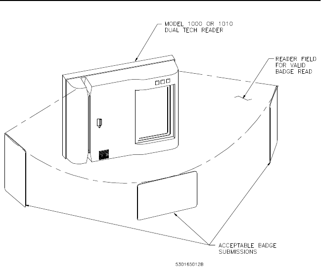
Functional Specifications
Product Operation: The reader transmits a wake-up field extending all
around the reader. When a badge is presented, energy from the field
powers the electronics inside the badge allowing it to transmit its unique
data to the reader. The reader receives, interprets, and checks the data,
sending only uncorrupted badge data to the microcontroller. Due to the
nature of the wake-up field, the maximum read range will be realized only
if the badge is presented to the reader on an imaginary semi-circle
centered on the reader, as shown below.
FIGURE 15: Badge to Reader Presentation
In the supervised modes, the reader also monitors and reports the status
of a normally-closed door contact switch and a normally-open exit
request push button.
A magnetic read head detects ABA encoded numeric data on track two of
a magnetic stripe card when the card is passed across the head. The
reader interprets this data and sends only valid card data to the host
Model 1000/1010 Dual Tech (Prox/MagStripe) Reader 39
controller. The reader monitors and reports the status of a door contact
and an exit request pushbutton (in supervised mode).
Application: Intended for areas requiring a moderately high level of
security for controlled access.
Compatibility: All CASI-RUSCO systems.
Reader Technology Type: F/2F magnetic stripe technology reading
track two and CASI-RUSCO ProxLite and Proximity Perfect Read-Only
Technology.
Parts List:
Model 1000 Reader
Model 1010 Reader
Optional 1000/1010 to 5029 Mounting Plate
Optional Housing, Surface Mount
Optional Tool, 1/8 inch Hex Tamper Key
Optional 1000/1010 Cold Weather Kit
Weather-Resistant Gasket
Badge Formats: First 4- to 16-digit number conforming to the ABA
(IBM) Standard for track two numeric data for magnetic stripe and
10-digit or 12-digit for proximity badges.
Mounting: The reader offers great flexibility in mounting. It is supplied
with a backplate suitable for mounting on a gang box. Optional surface
mount back boxes and a 5029 backplate are available. Most existing
mountings for the Model 5029 are compatible with this unit. A hex
tamper key tool must be purchased to install the reader.
Appearance: Attractive and durable light grey polycarbonate housing.
Indicators: Red, yellow, and green LEDs and a beeper are incorporated
into the reader.
•Red LED: Normally on when power is applied to the reader. The
red LED flashes to indicate a tamper condition or the loss of
communication with the microcontroller. In either case, the reader
will not read badges.
•Yellow LED: Blinks off briefly to indicate that a badge has been read
and sent to the microcontroller. When using the keypad (Model
1010), the LED turns on to indicate a keypress has been received by
the microcontroller and remains on to indicate that the
microcontroller is still waiting for remaining keys; if it goes off before
all keys are pressed, the sequence must be started again.
40 Model 1000/1010 Dual Tech (Prox/MagStripe) Reader
The first 5 seconds after power-up indicate the status of the Exit
request switch. If the Exit request switch is closed, the yellow LED
will be on; if open, the LED will be off.
•Green LED: When on, indicates that the microcontroller has
activated the door strike; it remains on for as long as the door strike is
activated. The first 5 seconds after power-up indicate status of the
door DI switch. If this switch is closed, the green LED will be on; if
open, the LED will be off.
•Beeper: The beeper sounds briefly to indicate that a valid badge has
been read or that a key has been pressed (Model 1010). A short triple
beep sounds to indicate a tamper condition or lack of communication
with the microcontroller.
Reader/Microcontroller Communications: The reader sends badge
data or reader status data to the microcontroller approximately once
every second and waits for an acknowledgment from the microcontroller.
The reader continues sending the data every second until an
acknowledgment is received. If an acknowledgment is not received after
the third attempt, the red LED starts flashing. Once the reader receives an
acknowledgment, the red LED stops flashing.
Badge Read Operation: Each time the reader sends badge data, the
yellow LED blinks off briefly and the beeper sounds. On systems set up
for PIN entry only, the yellow LED is on to indicate that keypad data is
expected.
Keypad Operation (Model 1010 only): This function requires
supervised mode. The reader sends each new keypress to the
microcontroller and blinks the yellow LED off. The beeper sounds while a
key is pressed.
Reader Tamper Operation: The readers incorporate a tamper switch.
While the reader is separated from its backplate, all badge-reading
functions are disabled, a tamper condition is indicated by a triple beep,
the red LED flashes, and all communications with the microcontroller are
suspended, taking the reader off line.
The reader is also equipped with an external tamper feature. To activate
this feature, connect a single-pole, single-throw (SPST), normally-closed
push-button switch (installer supplied) to connector J6 on the printed
circuit board assembly and install the switch between the wall and reader
backplate. When the reader and the backplate are removed from the wall,
the switch will close; therefore, closing the connection at J6 causing a
tamper condition.
Model 1000/1010 Dual Tech (Prox/MagStripe) Reader 41
Door Contact and Exit Request Inputs: The readers have a door
contact switch input and an exit request switch input. In supervised
mode, the state of both switch inputs is periodically reported to the
microcontroller, but changes to switch inputs are reported immediately.
Relay: Jumper-selectable normally closed and normally open contacts
are supplied for use with fail-safe or fail-secure door strikes.

42 Model 1000/1010 Dual Tech (Prox/MagStripe) Reader
NOTES