63 2235_D Q7130A, Q7230A, Q7330AModutrol IV Interface Modules Installation Directions
2016-10-06
: Pdf 1000377823-Installationsheet 1000377823-InstallationSheet B5 unilog
Open the PDF directly: View PDF ![]() .
.
Page Count: 8
INSTALLATION INSTRUCTIONS
Put Bar Code Here
63-2235-07
Q7130A, Q7230A, Q7330A
Modutrol IV Interface Modules
APPLICATION
The Q7130, Q7230, and Q7330 Modutrol IV Interface
Modules are used with Series 90 Modutrol IV Motors (M91XX)
for conversion to electronic (Series 70) control.
FEATURES
• Mounts inside the wiring box of any Series 90 Modutrol
IV Motor (M91XX models). Module protected from
weather by the Modutrol IV NEMA 3 wiring box.
• Mates to quick-connect terminals in motor wiring box
and provides screw terminals for control wiring
connections.
• Features solid state circuitry with surface mount
components.
• Plastic enclosure provides easy handling and
protection for circuitry.
• Q7130A provides selectable voltage range (4-7, 6-9, or
10.5-13.5 Vdc). Adapts M91XX Modtrol IV Motor to
function as M71XX model for M734H,J, M744D,
M745G,P replacements. Includes reversing switch to
allow replacement of electrically normally open or
electrically normally closed motors.
• Q7230A provides current or voltage control (4-20 mA
and 2-10 Vdc) with adjustable zero and span. Adapts
the M91XX Modutrol IV Motor to function as M72XX
model for M744S,T,Y or M745S,T,Y replacements.
Includes reversing switch to allow replacement of
electrically normally open or electrically normally
closed motors.
• Q7330A is an interface to W936 and W945 controls.
Adapts the M91XX Modutrol IV Motor to function as
M73XX model for M734D, M744A, M745A replacements.
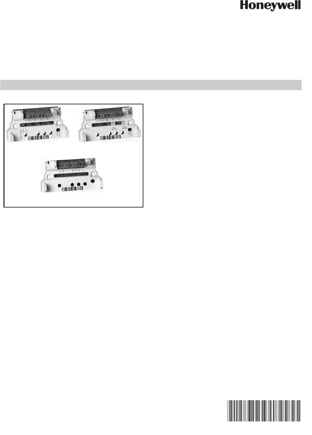
Q7130A Q7230A
Q7330A
Q7130A, Q7230A, Q7330A MODUTROL IV INTERFACE MODULES
63-2235—07 2
SPECIFICATIONS
IMPORTANT:
The specifications given in this publication do not
include normal manufacturing tolerances. Therefore,
this unit may not exactly match the listed specifica-
tions. Also, this product is tested and calibrated
under closely controlled conditions and some minor
differences in performance can be expected if those
conditions are changed.
Models:
Q7130A Modutrol IV Interface Module:
Used with M91XX Modutrol IV Motor to replace M71XX
Motor applications. Module controls only one motor.
See Table 1.
Q7230A Modutrol IV Interface Module:
Used with M91XX Modutrol IV Motor to replace M72XX
Motor applications. Module controls only one motor.
See Table 1.
Q7330A Modutrol IV Interface Module:
Used with M91XX Modutrol IV Motor to replace M73XX
Motor applications. Module controls only one motor.
See Table 1.
Electrical Ratings:
Input Voltage: 24 Vac, 50/60 Hz.
Power Consumption: 2 VA.
Input Impedance:
Q7130A: >100k ohms.
Q7230A: voltage input >100k ohms; current input 67 ohms.
Temperature Rating: -40° F to +150° F [-40° C to + 66° C].
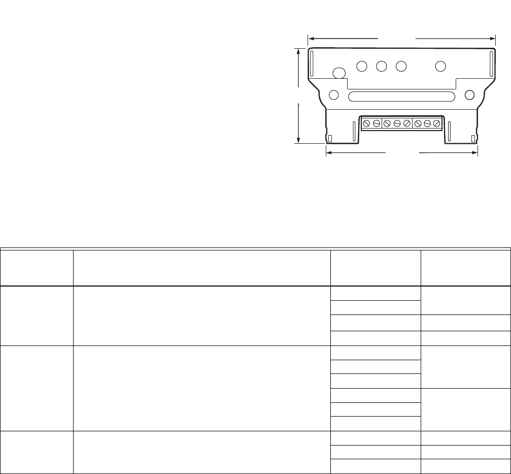
Dimensions: See Fig. 1.
Fig. 1. Q7130,Q7230,Q7330 Modutrol IV Interface Module
dimensions in in. (mm).
aRefer to customer.honeywell.com for cross-reference details.
bM744D1037 and M744D1045 do not apply.
M27211
3-25/32 (96)
1-59/64
(49)
3-5/64 (78)
Table 1. Interface Module Function/Application Chart.
This Model Provides Interface For
And Replaces
These Old Style
MotorsaWhen Used with
Series 90 Models:
Q7130A Selectable voltage ranges: 4-7, 6-9, or 10.5 to 13.5 Vdc M734H M9164D1009
M734J
M744DbM9184D1021
M745G M9185A1018
Q7230A Adjustable zero and span, voltage or current M9184D1021
control (includes 4-20 mA and 2-10 Vdc).
M744S M9184D1021
M744T
M744Y
M745S M9185D1004
M745T
M745Y
Q7330A W936 or W945 control interface. M734D M9164D1009
M744A M9184D1021
M745A M9185D1004

Q7130A, Q7230A, Q7330A MODUTROL IV INTERFACE MODULES
363-2235—07
INSTALLATION
When Installing This Product…
1. Read these instructions carefully. Failure to follow them
could damage the product or cause a hazardous condi-
tion.
2. Check the ratings and description given in this specifi-
cation to make sure the product is suitable for your
application.
3. Installer must be a trained, experienced service techni-
cian.
4. After installation is complete, check out product opera-
tion as provided in these instructions.
5. Excessive force can damage potentiometer con-
trols.
Use a small screwdriver when adjusting all potentiome-
ters located on the unit.
CAUTION
Disconnect power before installation to prevent
electrical shock or equipment damage.
IMPORTANT:
For ease of adjustment, make all stroke and auxiliary
switch adjustments before installing the interface
module. After installation, access to the stroke adjust
cams and auxiliary switches inside the motor is
restricted. For complete details on performing these
adjustments, refer to the specification sheet packed
with the Modutrol Motor.
Installing Terminal Block
CAUTION
When installing the terminal block on the motor
quick connects, push the board straight down.
Rocking or tilting of the board can damage the
electrical connectors and result in an inoperative
wiring module.
1. Disconnect power from the M91XX Modutrol IV Motor to
prevent electrical shock or equipment damage.
2. Remove wiring box cover from the motor by removing
four screws.
3. Disconnect all field wiring from the motor.
4. If motor has an internal transformer, make sure trans-
former is not powered and disconnect secondary wires
from T1 and T2 terminals. Clip quick-connect termina-
tions from transformer secondary (brown) wires. Trim
1/8 to 1/4 in. (3 to 6 mm) of insulation from the ends of
the wire. Tin wire ends with solder.
5. Plug terminal block onto quick-connect terminals inside
wiring box.
6. Connect field wiring to screw terminals on terminal
block. See Fig. 3, 5, and 9 for terminal designations.
Trim wire ends neatly and tin with solder.
7. Position circuit module and secure.
SETTINGS AND ADJUSTMENTS
Module Adjustments
Q7130A Adjustments (Fig. 3)
The Q7130A provides selectable range, two-wire voltage
control (4-7, 6-9 or 10.5-13.5 Vdc). It includes a clockwise/
counterclockwise (cw/ccw) switch for replacing electrically
normally open or electrically normally closed motors. Please
remove film from CW/CCW switch before use.
1. Set Mod IV motor pots—both CW or both CCW for your
application. Use the checkout procedure in Table 2 to
ensure proper motor function.
2. Select desired voltage range using the three-position
switch reference chart for dip switch settings (see Fig.
2).
3. Select desired rotation. Select cw for electrically nor-
mally closed (motor drives clockwise , as viewed
from power end, to open with an increase in control sig-
nal). Select ccw for electrically normally open (motor
drives counterclockwise , as viewed from power
end, to close with an increase in control signal) (default
switch position is clockwise).
4. See Fig. 4 for typical system wiring.
5. Set controller to drive motor to fully open position and
then to fully closed position to check for proper opera-
tion.
Fig. 2. DIP switch reference.
M29165
4-7
Q7130
6-9
10.5-13.5
Q7130A, Q7230A, Q7330A MODUTROL IV INTERFACE MODULES
63-2235—07 4
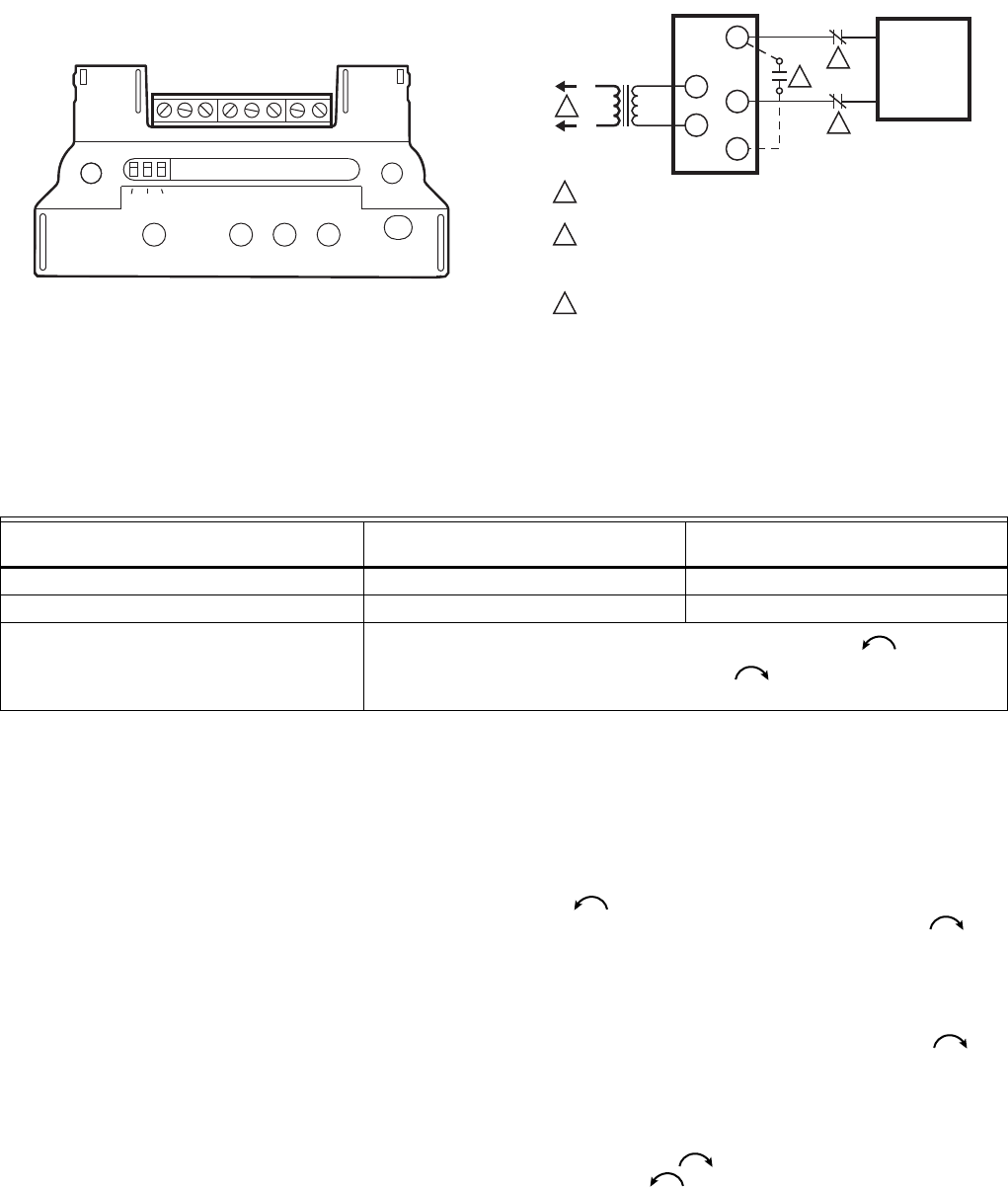
Fig. 3. Q7130A terminals and adjustments.
Fig. 4. Typical system wiring for Q7130A Interface Module
and M91XX Modutrol Motor.
Q7230 Adjustments (Fig. 5 and Table 3)
The Q7230A provides adjustable range (zero and span) for
two-wire current or voltage control. Separate potentiometers
are provided on the circuit module for adjusting the zero point
and the span. It includes a cw/ccw switch for configuring the
motor to rotate clockwise or counterclockwise with an
increase in control signal.
1. Set Mod IV motor pots—both CW or both CCW for your
application. Use the checkout procedure in Table 3 to
ensure proper motor function.
2. Verify that the zero potentiometer is fully clockwise and
that the span potentiometer is fully counterclockwise.
(Do not exceed the stop point of the potentiometer.)
3. Select desired rotation direction [cw (electrically nor-
mally closed) is the most common]. The following direc-
tions apply for the clockwise setting. For
counterclockwise setting, reverse open and closed, and
reverse clockwise and counterclockwise. Remove film
on switch before use. (Default switch position is CW.)
4. See Fig. 7 and 8 for typical system wiring.
5. For current control, connect the current input signal to I+
(screw terminal 3) and COM (screw terminal 5). For
voltage control, connect the voltage input signal to V+
(screw terminal 1) and COM (screw terminal 5).
6. Set the controller to output the signal required to drive
the motor to the closed position. Wait for the motor to
stop driving closed.
7. Turn the zero potentiometer slowly counterclockwise
until the motor starts to open.
8. Turn the zero potentiometer slowly clockwise
until the motor is fully closed. This is defined as the zero
setting.
9. Set the controller to output the signal required to drive
the motor to the fully open position. Wait for the motor to
stop driving open.
10. Turn the span potentiometer slowly clockwise
until the motor starts to drive closed. The difference
between the fully open position signal and the fully
closed position signal is defined as the operating span.
11. Recheck the fully closed position and readjust the zero
potentiometer, if necessary. (Turn the zero potentiome-
ter clockwise to close the motor and counter-
clockwise to open the motor.)
M27212
T1 T2 FC+ A–
10.5-13.5
CCW
CW
6.9
4.7
POWER SUPPLY. ADD DISCONNECT MEANS AND OVERLOAD
PROTECTION AS REQUIRED.
OPTIONAL NORMALLY OPEN SWITCH. WITH CCW SELECTION,
MOTOR WILL RUN TO FULLY CLOSED; WITH CW SELECTION
MOTOR WILL RUN TO FULLY OPEN WHEN THIS SWITCH CLOSES
(AS LONG AS POWER IS APPLIED TO T1, T2 TERMINALS).
OPTIONAL NORMALLY CLOSED SWITCHES. FINE SILVER OR
DRY CONTACTS REQUIRED. WITH CCW SELECTION, MOTOR
WILL RUN TO FULLY OPEN; WITH CW SELECTION, MOTOR WILL
RUN TO FULLY CLOSED WHEN SWITCH IN EITHER C OR R
LEAD IS OPENED.
1
M505C
T1
T2
24V
L1
(HOT)
L2
MODULATING
DC VOLTAGE
SOURCE
C
R
3
+
–
TRANSFORMER
2
3
1
F
3
MOTOR
2
Table 2. Q7130A/M91XX Checkout Procedure.
Step
Proper Motor Response Switch in
Clockwise Position Switch in Counterclockwise Position
1. Open terminal C or R. Motor runs closed (fully ccw). Motor runs open (fully cw).
2. Jumper terminals C and F. Motor runs fully open (fully cw). Motor runs fully closed (fully ccw).
3. Remove either T terminal or disconnect
power supply. Spring return motors return to normal spring position (fully ccw for
mechanically normally closed motors; fully cw for mechanically normally
open motors).
Q7130A, Q7230A, Q7330A MODUTROL IV INTERFACE MODULES
563-2235—07
12. Recheck the fully open position and readjust the span
potentiometer, if necessary. (Turn the span potentiome-
ter clockwise to close the motor, counterclockwise to
open the motor.) Verify the mid point of your stroke.
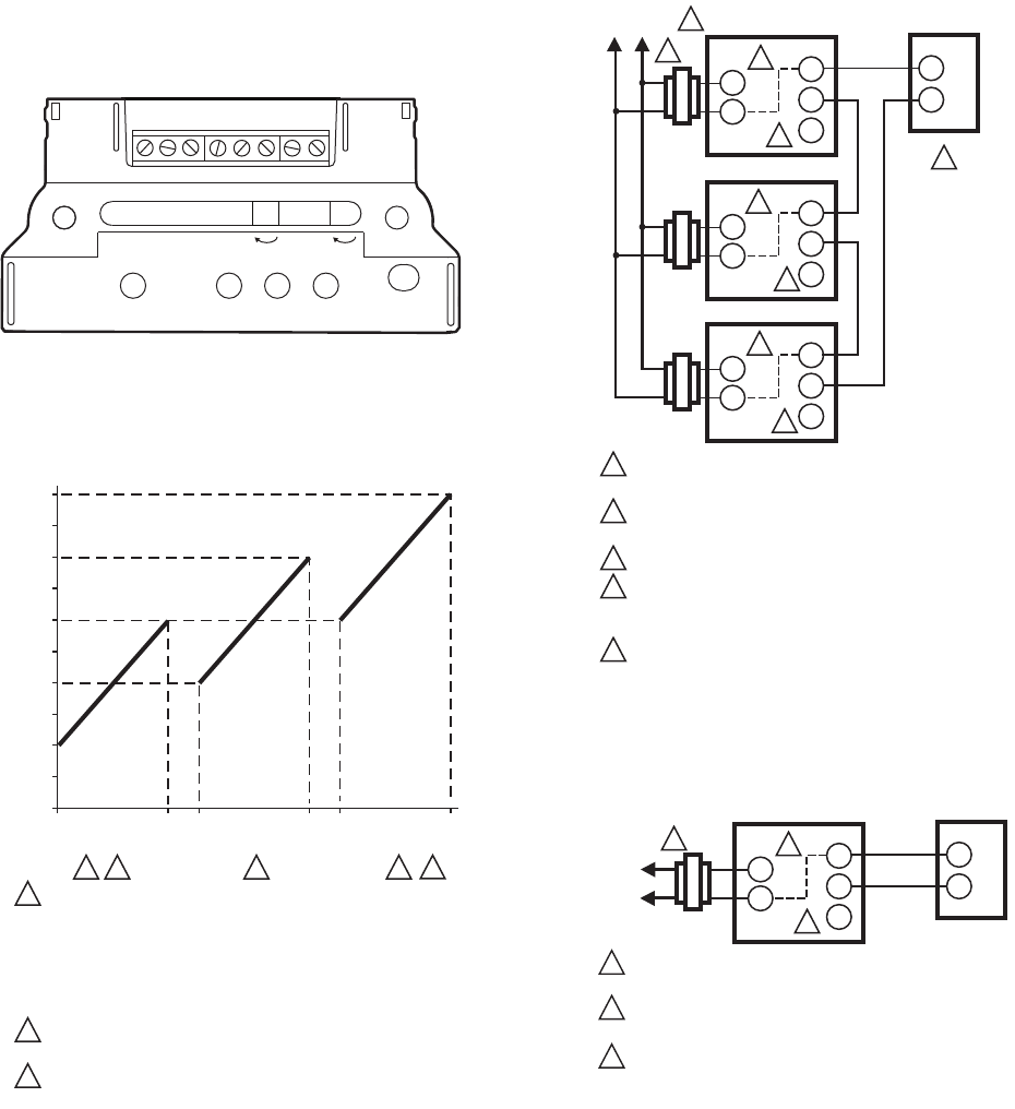
Fig. 5. Q7230A terminals and adjustments.
Fig. 6. Sequential operation of three motors with Q7230A
Interface Module.
13. For sequential operation at two or more motors (as
shown in Fig. 6), repeat the above steps for each motor,
individually adjusting each for the desired response to
the input signal.
Fig. 7. Typical wiring diagram for Q7230A Interface
Module and M91XXX Modutrol IV Motor with 4-20 mA
controller.
Fig. 8. Typical wiring diagram for Q7230A Interface
Module and M91XXX Modutrol IV Motor with 2-10 Vdc
controller.
M27213
T1 T2 FCom V+
CCW
CW
ZEROSPAN
1+
20
(10)
16
(8)
12
(6)
8
(4)
4
(2)
0
CONTROL OUTPUT
mA CURRENT (OR VOLTS DC)
CLOSED OPEN CLOSED OPEN CLOSED OPEN
MOTOR 1 MOTOR 2 MOTOR 3
1 3 3 3
1MOTOR 1 PROPORTIONS BETWEEN 4 AND 12 mA; FULLY
CLOSED AT 4 mA, FULLY OPENED AT 12 mA.
MOTOR 2 PROPORTIONS BETWEEN 8 AND 16 mA; FULLY
CLOSED AT 8 mA, FULLY OPENED AT 16 mA.
MOTOR 3 PROPORTIONS BETWEEN 12 AND 20 mA SIGNAL;
FULLY CLOSED AT 12 mA, FULLY OPENED AT 20 mA.
UP TO 6 MOTORS CAN BE DRIVEN SEQUENTIALY OR IN
UNISON FROM ONE CONTROLLER.
ADJUST ZERO ADJUST AND SPAN ADJUST POTENTIOMETERS
TO ACHIEVE DESIRED SEQUENCE.
2
2
3
SEQUENTIAL OPERATION
FOR ADJUSTABLE ZERO AND SPAN MODELS
M2893A
4
4-20 mA
CONTROLLER
L1
(HOT)
L2
POWER SUPPLY. PROVIDE DISCONNECT MEANS AND
OVERLOAD PROTECTION AS REQURED.
CONNECTING TO EITHER (+) OR (-) WILL DRIVE THE
MOTOR TO FULLY OPEN.
DRIVE UP TO SIX MOTORS IN UNISON.
EACH MOTOR MUST HAVE SEPARATE TRANSFORMER.
IF COMMON LINE VOLTAGE SUPPLY MUST BE USED,
ADD ISOLATION TRANSFORMER TO EACH M91XX MOTOR.
INTERNAL MODUTROL IV CONNECTION.
1
M506H
1
3
MOTOR
MOTOR
+
–
MOTOR
2F
I+
COM
T1
T2
5
5
2F
I+
COM
T1
T2
5
2F
I+
COM
T1
T2
5
2
3
4
2-10 Vdc
CONTROLLER
L1
(HOT)
L2
POWER SUPPLY. PROVIDE DISCONNECT MEANS AND
OVERLOAD PROTECTION AS REQURED.
CONNECTING TO EITHER (+) OR (-) WILL DRIVE THE
MOTOR TO FULLY OPEN.
INTERNAL MODUTROL IV CONNECTION.
1
M29166
1
+
–
MOTOR
2F
V+
COM
T1
T2
3
2
3
Q7130A, Q7230A, Q7330A MODUTROL IV INTERFACE MODULES
63-2235—07 6
(+) and (-) denotes terminals on the controller
Q7330A Adjustments (Fig. 9 and Table 4)
The Q7330A provides control interface for W936 and W945
controllers. This module consists only of the terminal block
and does not require any adjustments. See Fig. 9 for
terminals.
After the motor stroke is adjusted (if necessary), simply plug
the module onto the motor quick-connect terminals and
secure to the motor. See Fig. 10 for typical system wiring.
To check proper motor operation:
1. Provide power to the motor.
2. Jumper terminals 1 and 2 to drive motor open (clock-
wise as viewed from power end).
3. Jumper terminals 1 and 3 to drive motor closed. Con-
nect field wiring to appropriate screw terminals.
Fig. 9. Q7330A terminals.
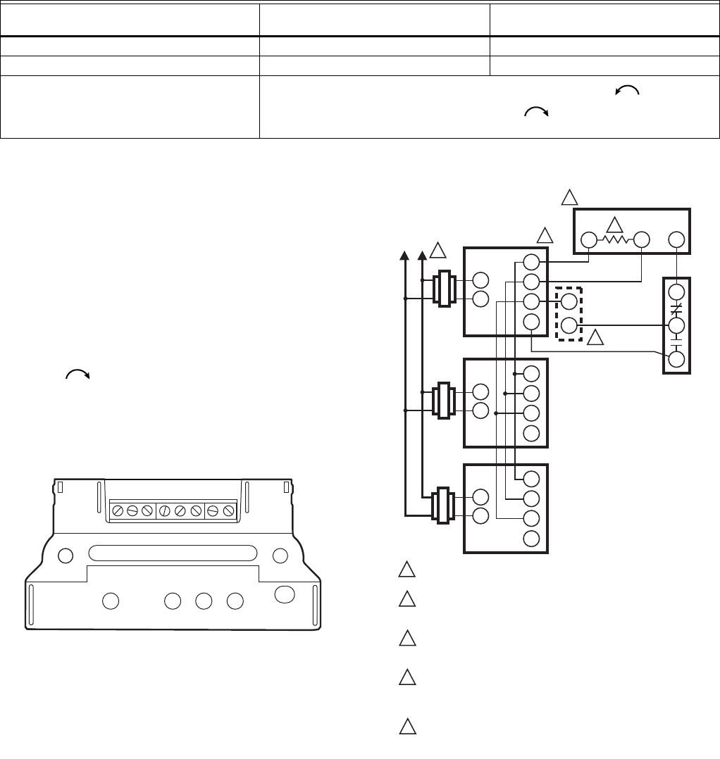
Fig. 10. Typical wiring diagram for Q7330A Interface
Module and M91XX Modutrol IV Motor.
Table 3. Q7230/M91XX Checkout Procedure.
Step
Proper Motor Response Switch in
Clockwise Position Switch in Counterclockwise Position
1. Open terminals (+), (-), F Motor closes fully ccw Motor opens fully cw
2. Jumper F to (-) Motor opens fully cw Motor closes fully ccw
3. Remove either T terminal Spring return motors return to normal spring position (fully ccw for
mechanically normally closed motors, fully cw for mechanically normally
open motors).
M27214
T1 T2 431
2
4
L1
(HOT) L2
POWER SUPPLY. PROVIDE DISCONNECT MEANS AND
OVERLOAD PROTECTION AS REQURED.
SEE APPROPRIATE SYSTEM CONTROL INSTRUCTIONS
FOR CONNECTIONS TO CENTRAL PROCESSOR.
(LABELED E1 ON W936 OR T1 ON W945).
FIVE PERCENT CARBON RESISTOR. VALUE VARIES WITH
NUMBER OF MOTORS PARALLELED (1000 OHMSÐ2 MOTORS,
820 OHMSÐ3 MOTORS.
AUTHORITY OF MINIMUM POSITION POTENTIOMETER IF USED,
INCREASES WITH NUMBER OF MOTORS PARALLELLED (135
OHMS ON MOTORÐ50 PERCENT STROKE, ON 2 MOTORSÐ
100 PERCENT STROKE, ON 3 MOTORSÐ150 PERCENT STROKE).
USE AUXILIARY END OF M9185 TO REPLACE M945B; M745D
MOTORS TO SPRING RETURM TO THE NORMALLY OPEN
POSITION.
1
M487C
1
5
2
3
4
T1
T2
1
2
3
4
T1
T2
1
2
3
4
T1
T2
1
2
3
4
OPTIONAL
MINIMUM
POSITION
POTENTIOMETER
CHANGEOVER
CONTROLLER
3
ELECTRONIC
MODULATING
DAMPER MOTORS
ELECTRONIC
CENTRAL PROCESSOR
12
3
2
5

Q7130A, Q7230A, Q7330A MODUTROL IV INTERFACE MODULES
763-2235—07
Table 4. Q7330/M91XX Checkout Procedure.
Step
Proper Motor Response for Normally
Closed Motor
Proper Motor Response for Normally
Open Motor
1. Disconnect leads from terminals
1,2,3,4. Motor closes. (Fully ccw as
viewed from power end).
Motor opens. (Fully cw as viewed
from the power end)
2. With motor powered jumper terminals 1
and 2. Motor drives open (clockwise as
viewed from powered end).
Motor drives closed (counterclockwise
as viewed from the power end).
3. Remove either T terminal or disconnect
power supply. Spring return motors return to normal spring position (fully ccw for
mechanically normally closed motors, fully cw for mechanically normally
open motors.

Q7130A, Q7230A, Q7330A MODUTROL IV INTERFACE MODULES
Automation and Control Solutions
Honeywell International Inc.
1985 Douglas Drive North
Golden Valley, MN 55422
Honeywell Limited-Honeywell Limitée
35 Dynamic Drive
Toronto, Ontario M1V 4Z9
customer.honeywell.com
® U.S. Registered Trademark
© 2011 Honeywell International Inc.
63-2235—07 T.D. Rev. 01-11
Printed in U.S.A.
By using this Honeywell literature, you agree that Honeywell will have no liability for any damages
arising out of your use or modification to, the literature. You will defend and indemnify Honeywell, its
affiliates and subsidiaries, from and against any liability, cost, or damages, including attorneys’ fees,
arising out of, or resulting from, any modification to the literature by you.
