HID Global CEM603 RFID Reader CEM-603 User Manual
HID Global Corporation RFID Reader CEM-603
UserManual.wiki
>
HID Global
>
CEM603 User Manual
Manual
Navigation menu
Upload a User Manual
Namespaces
Wiki Guide
HTML
PDF
Info
Views
User Manual
Discussion / Help
Navigation

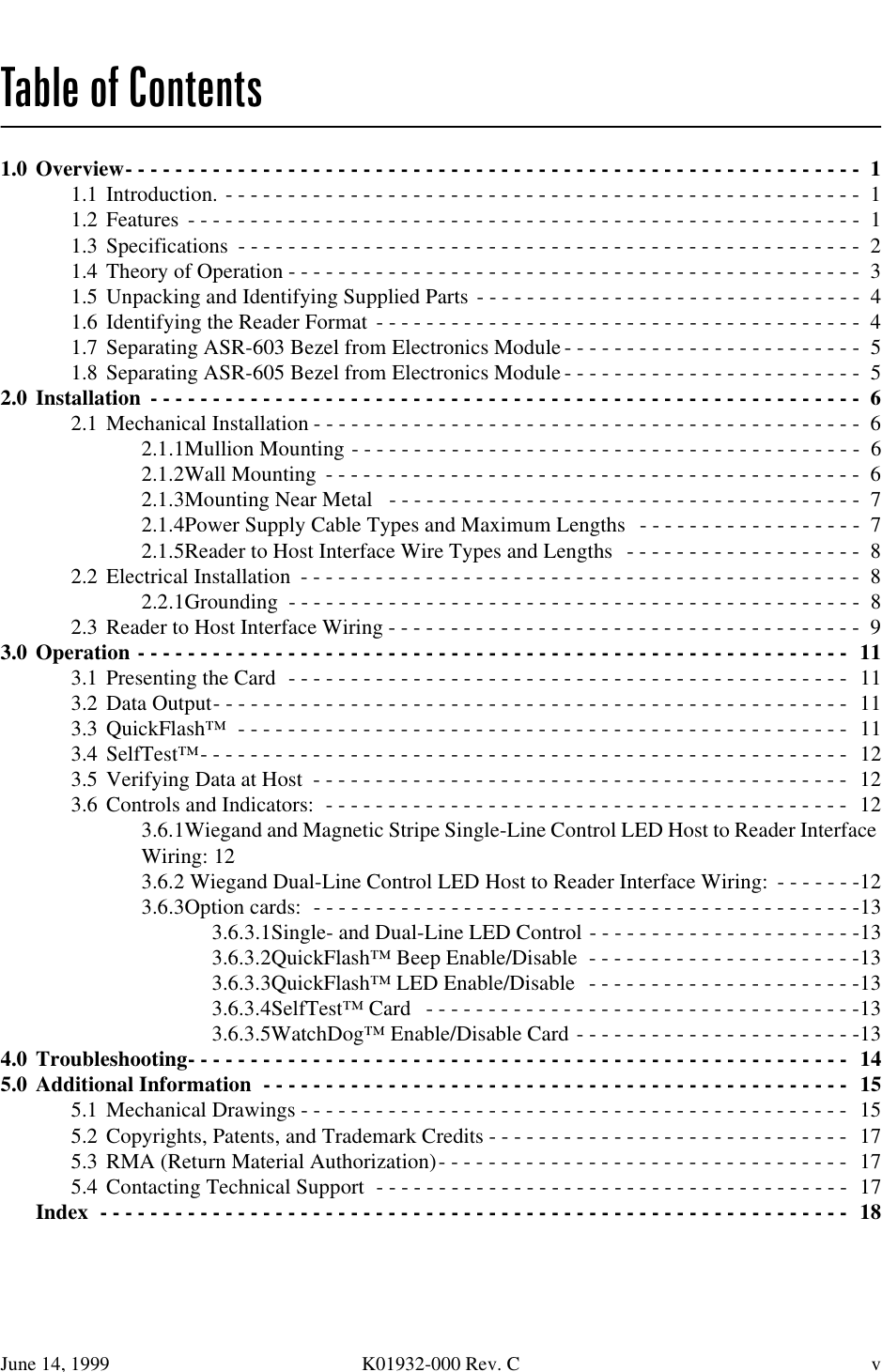
![June 14, 1999 K01932-000 Rev. C 5 6HSDUDWLQJ$65%H]HOIURP(OHFWURQLFV0RGXOHTo remove the ASR-603 reader bezel, unscrew the tamper screw, pull metal latch, and pull the readermodule up as shown in Figure 4. Figure 4. Separating ASR-603 Bezel From Module 6HSDUDWLQJ$65%H]HOIURP(OHFWURQLFV0RGXOHTo remove the ASR-605 reader bezel, unscrew the tamper screw, pull metal latch, and pull the readermodule up as shown in Figure 5. Figure 5. Separating ASR-605 Bezel From Module](https://usermanual.wiki/HID-Global/CEM603/User-Guide-114759-Page-11.png)
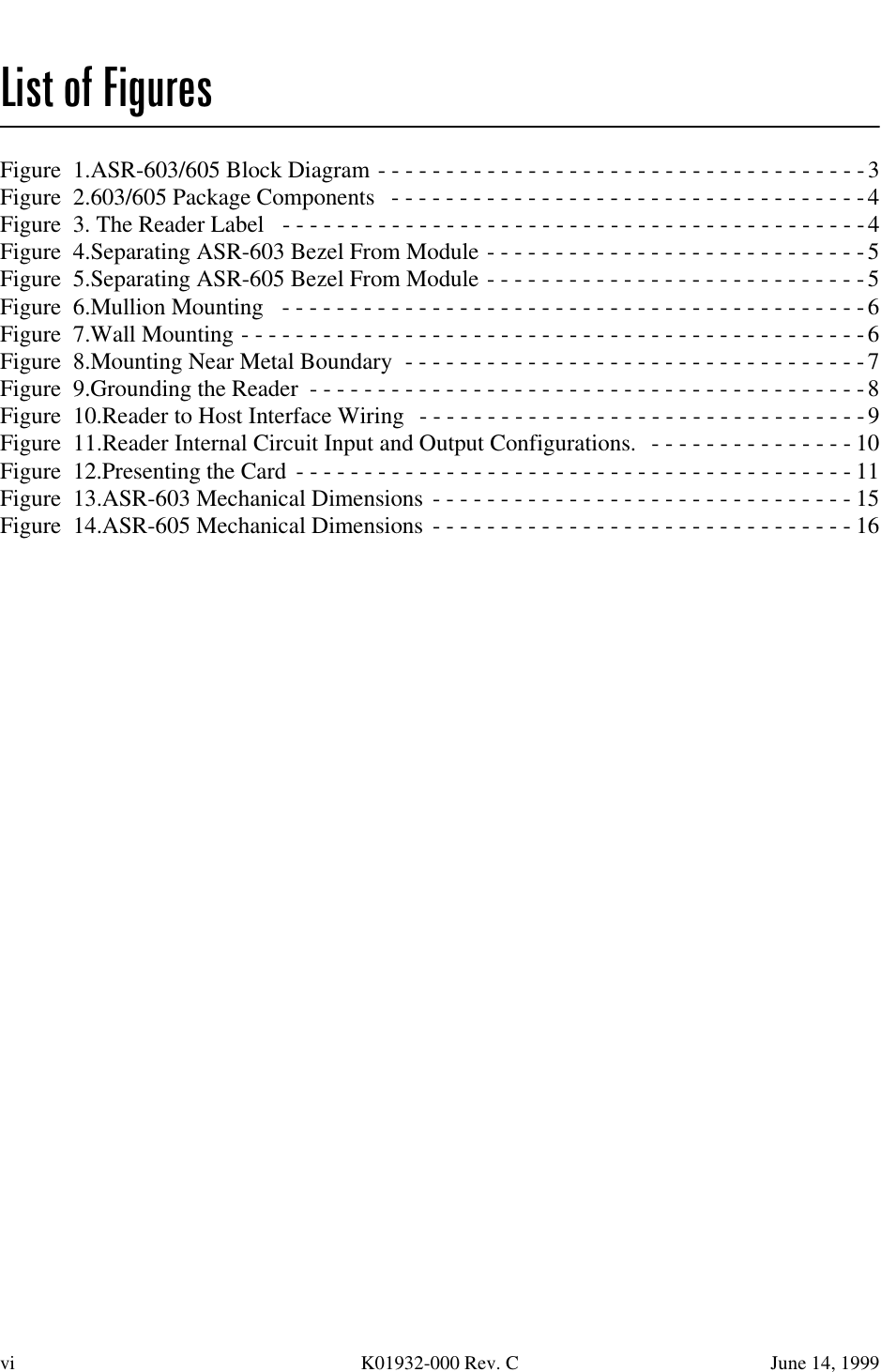
![June 14, 1999 K01932-000 Rev. C 17 &RS\ULJKWV3DWHQWVDQG7UDGHPDUN&UHGLWV© 1997 Indala Corporation. Motorola`s Indala Corporation reserves all rights including patents, copy-rights, trademarks, trade names, and all other intellectual property rights worldwide. No reproduction,adaptation, or translation is allowed without prior written permission from Motorola`s Indala Corpora-tion. Indala Corporation reserves the right to change any product description and/or specification con-tained here without prior notice. Products are covered by United States patent 4818855, Canadian patent 1253591, and other patentspending worldwide.Motorola and the Motorola logo are registered trade marks of Motorola, Inc. ASP, SelfTest™, Quick-Flash™, and WatchDogTM are trade marks of Indala Corporation. 50$5HWXUQ0DWHULDO$XWKRUL]DWLRQGoods returned for repair, warranty or non-warranty, must be assigned an RMA (Return MaterialAuthorization) number. The customer is to provide a description of the specific problem. The customeris to include serial numbers, formats, card ID numbers, and correct facility codes with the items to bereturned. If exact duplicates of returned cards or tags are requested, the customer must provide Motor-ola Indala with the exact format and ID numbers needed.For readers returned and not covered by the warranty (due to age, misuse and/or damage), a quote forrepairs will be issued, and no work will be performed until a valid purchase order is received. Read-ers left over 30 days without a repair authorization and a purchase order will be returned with evalua-tion charges and shipping costs applied. &RQWDFWLQJ7HFKQLFDO6XSSRUWPlease answer all questions in section 4.0 "Troubleshooting" and have your answers ready before youcall the technical support number listed below: U.S.A. Office:3041 Orchard ParkwaySan Jose, CA 95134-2017Tel (408) 383-4000, MainTel (800) 646-3252, Technical SupportFax (408) 434-7057](https://usermanual.wiki/HID-Global/CEM603/User-Guide-114759-Page-23.png)