3Com SRWL306 Wireless LAN Access Point, WL-306 User Manual SpeedRacerAccessPoint
3Com Corporation Wireless LAN Access Point, WL-306 SpeedRacerAccessPoint
3Com >
Contents
- 1. Users Manual Revised
- 2. Users Manual Regulatory Section Revised
- 3. Manual
Users Manual Revised
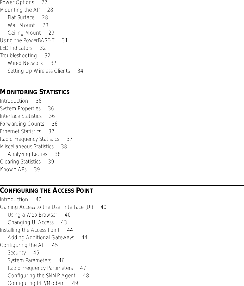
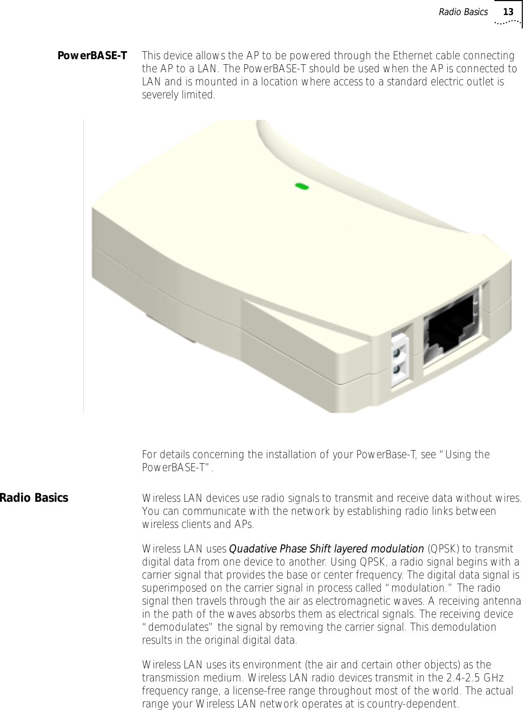
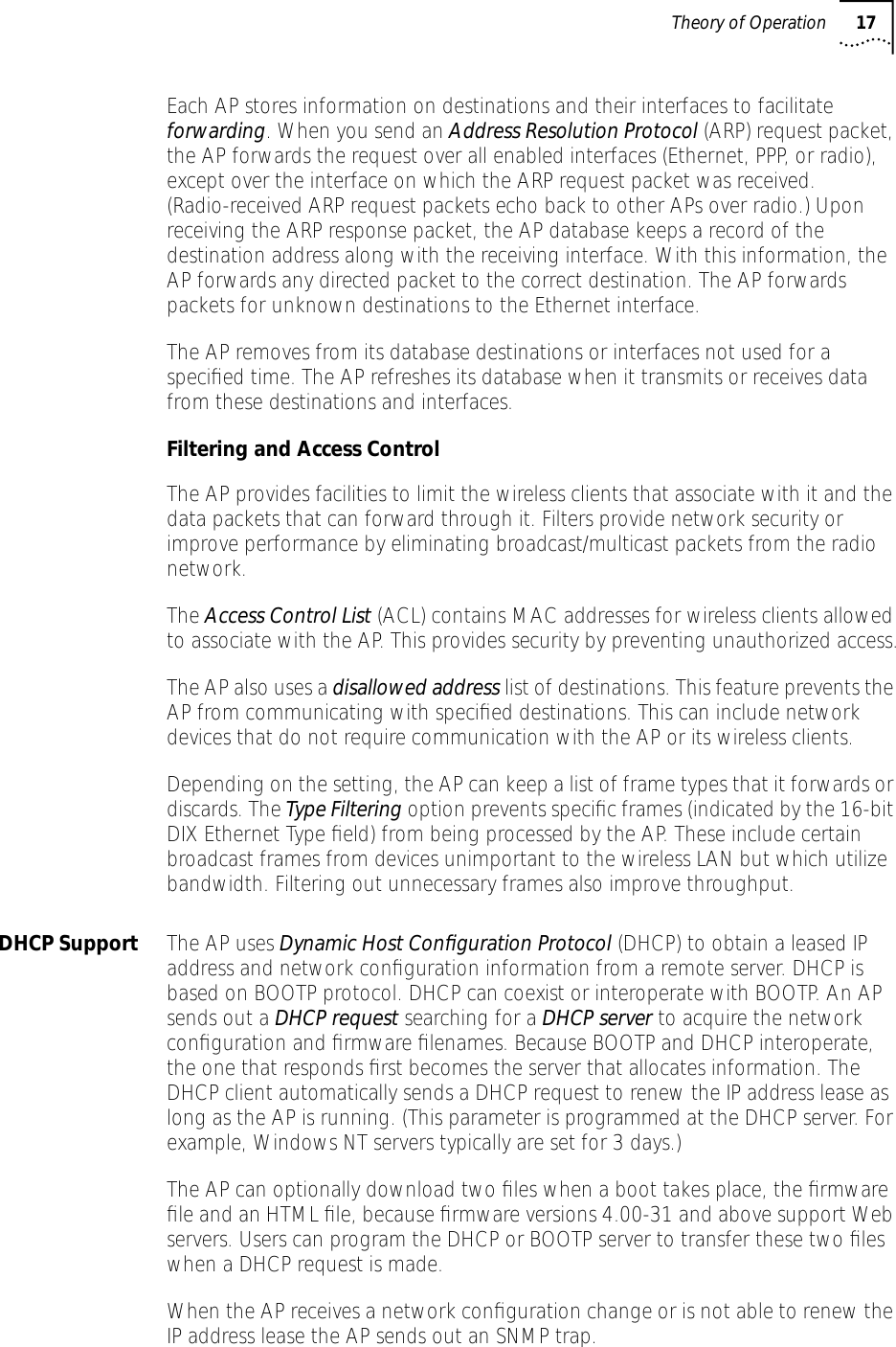
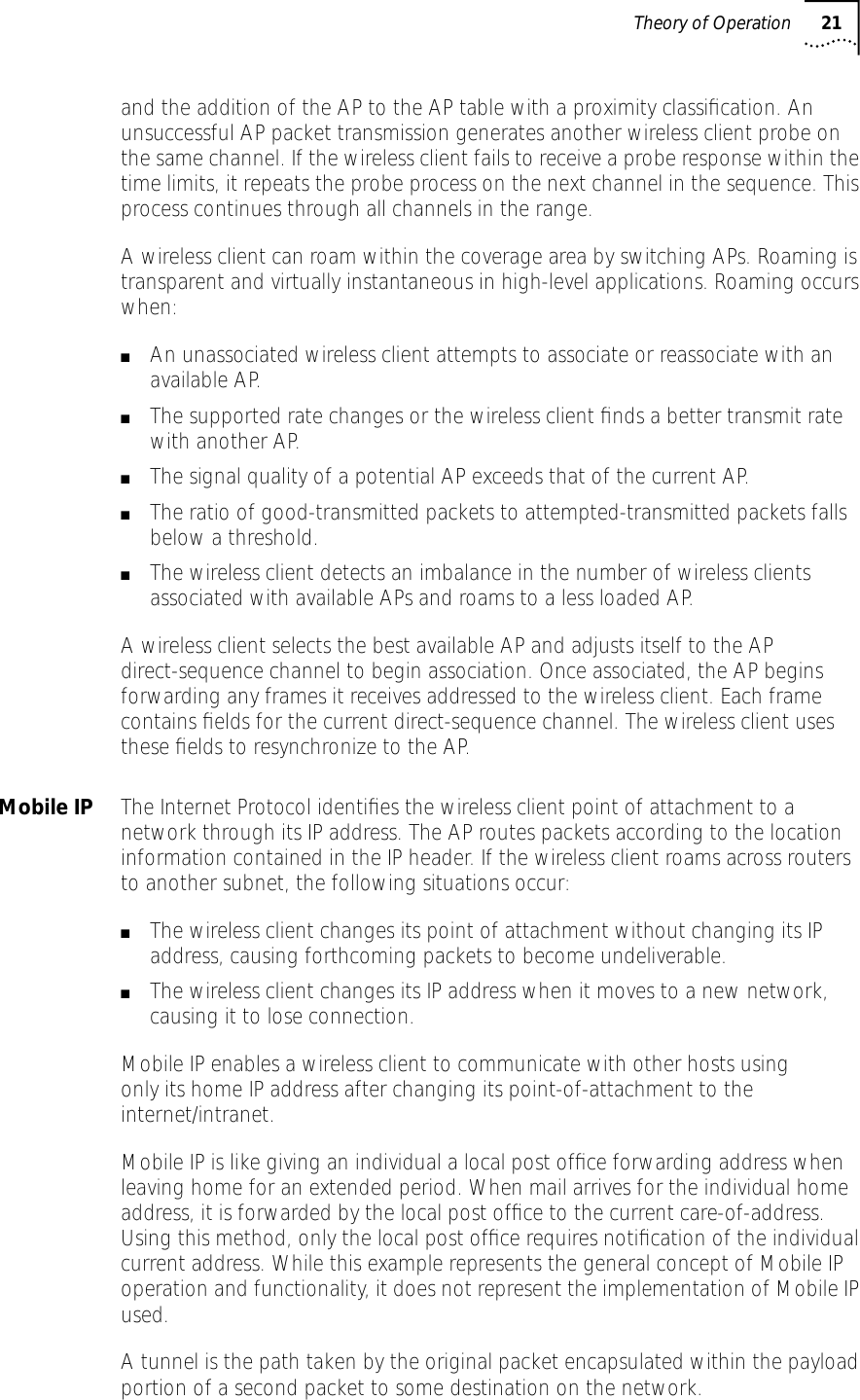
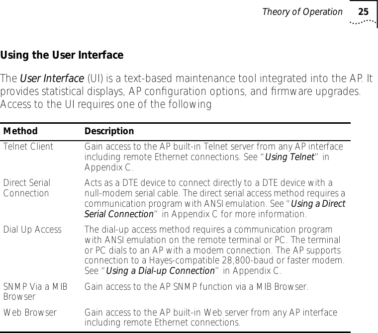
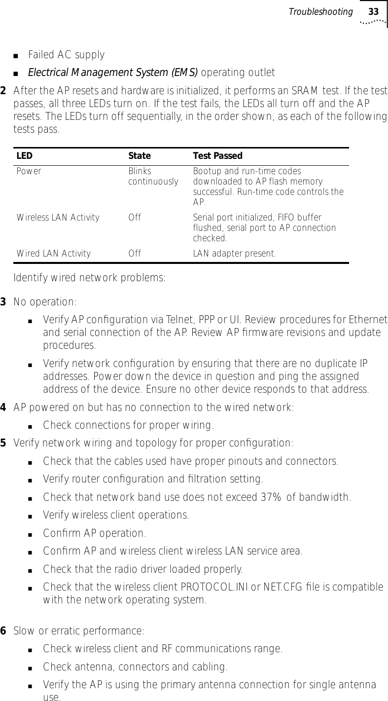
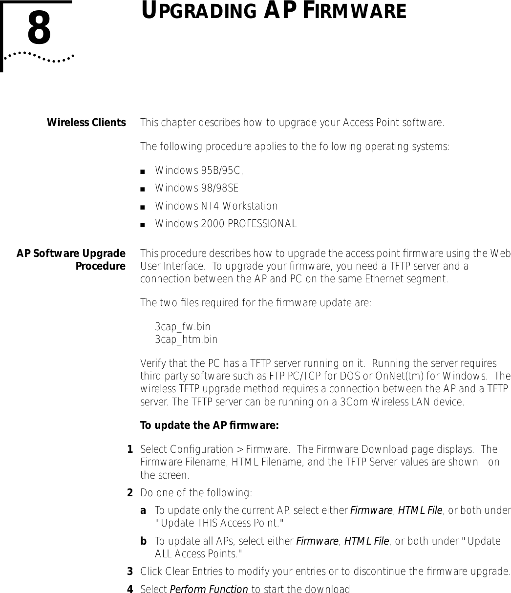
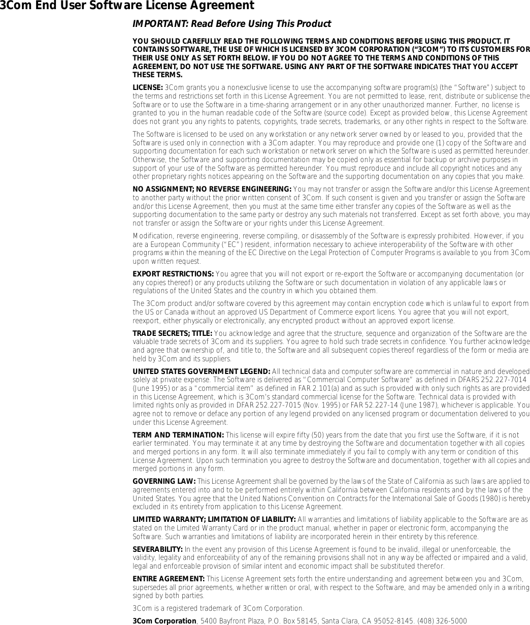
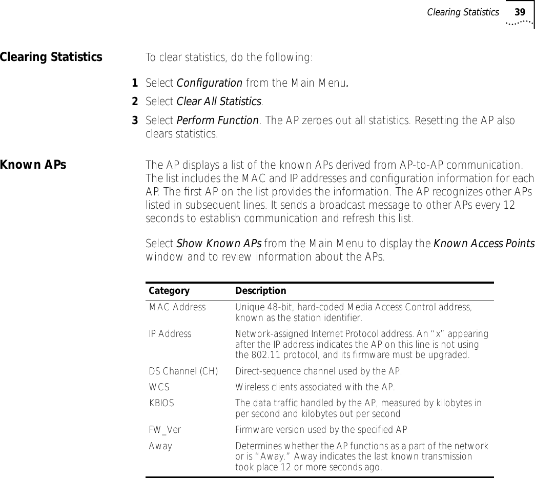
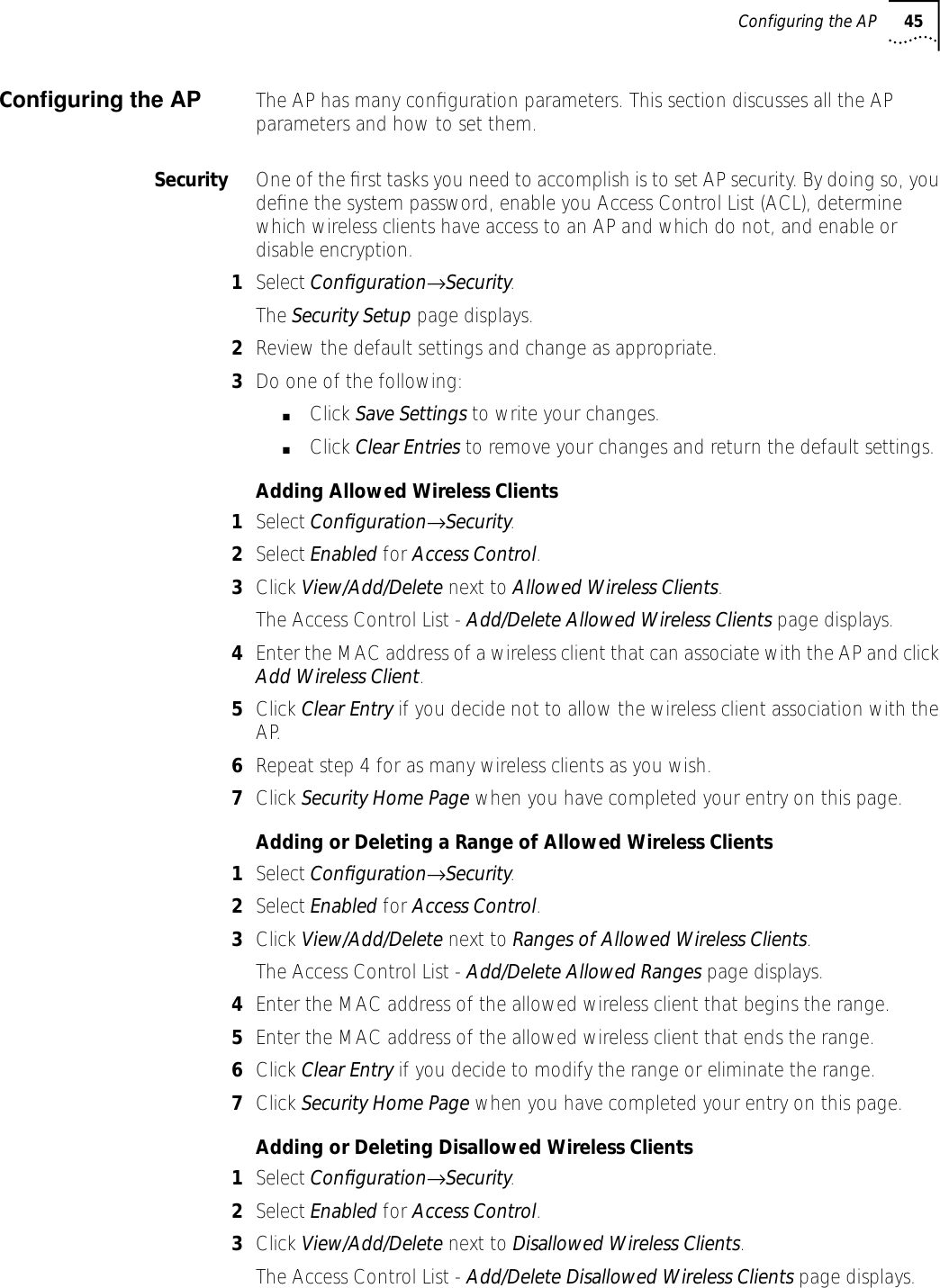
![38 CHAPTER 3: MONITORING STATISTICSMiscellaneous Statistics The AP keeps statistics on WNMP and SNMP packets, filtering violations, and serial port use in the Miscellaneous Statistics window. to display the Misc System Statistics window, select Main Menu→Misc Statistics.Select Refresh or press the F1 key to update the values manually. Select Timed or press the F2 key to have the AP automatically update the display every two seconds.Press Esc or Previous-[F4] to exit.Analyzing Retries The AP keeps statistics of packets with multiple retries. Use these statistics to identify severe occurrences of retries. Retries occur when the transmitting station fails to receive an acknowledgment for a transmitted packet. This lack of acknowledgment can result from:■Two or more stations transmitting simultaneously and causing collisions■The receiving station moving out of range■The receiving station being powered off.Any one of these incidents causes both devices to suspend transmitting and retry later. Too many retries can indicate a system problem.To view retry severity, do the following:1Select Statistics from the Main Menu.2Select Retry Histogram. The display indicates the packets that experience retries (up to 15 retries).3Press any key to return to the Main Menu.Type Name DefinitionWNMP Echoes Echo requests received by the AP.Pings Ping requests received by the AP.Passthrough Echoes Echoes for wireless clients associated with the AP.SNMP Requests Configuration requests received from the SNMP manager.Traps AP messages sent to the SNMP manager.Filter ACL Violations Attempts by wireless client(s) not in ACL list to associate with this AP.Address Packets discarded by address filter.Type Packets discarded by type filter.Modem Number of Dialouts Dial-out attempts by the AP.Dialout Failures Dial-out failures by the AP.Number of Answers Answer attempts by the AP.Current Call Time Current connection session length, in seconds.Last Call Time Last connection session length, in seconds.](https://usermanual.wiki/3Com/SRWL306.Users-Manual-Revised/User-Guide-139173-Page-38.png)
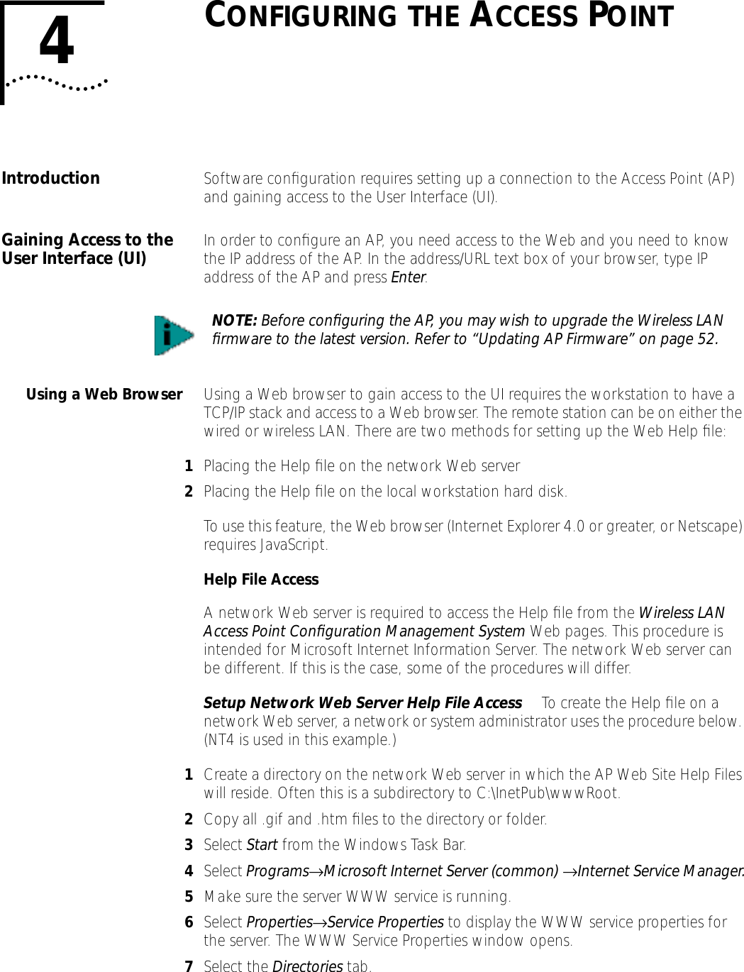
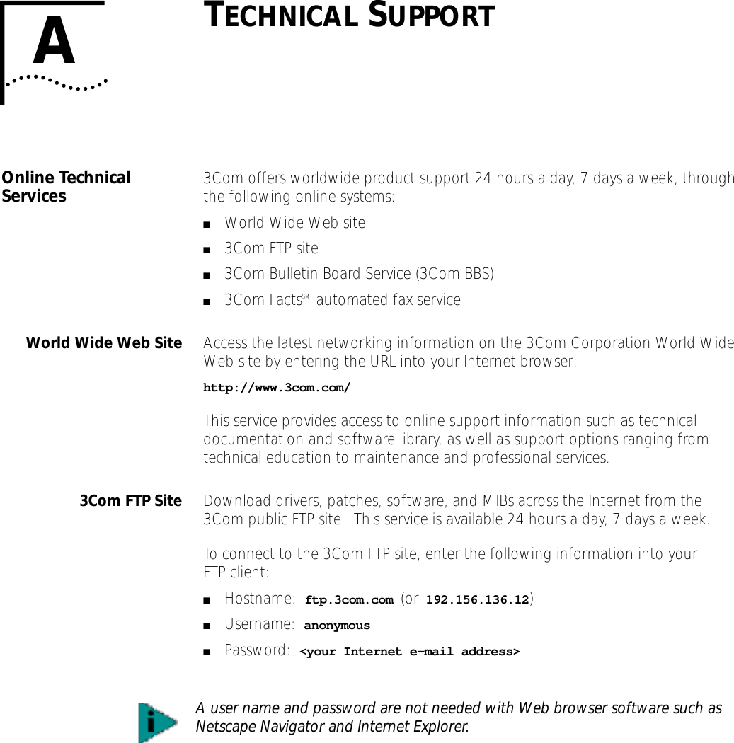
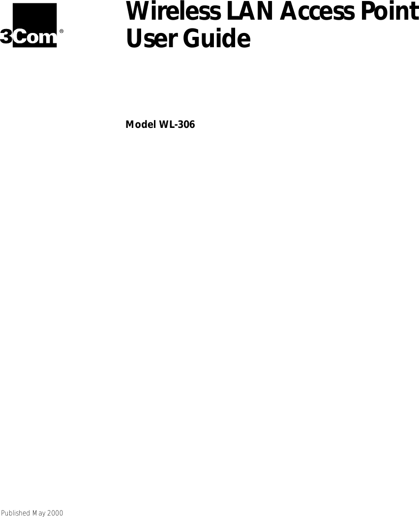
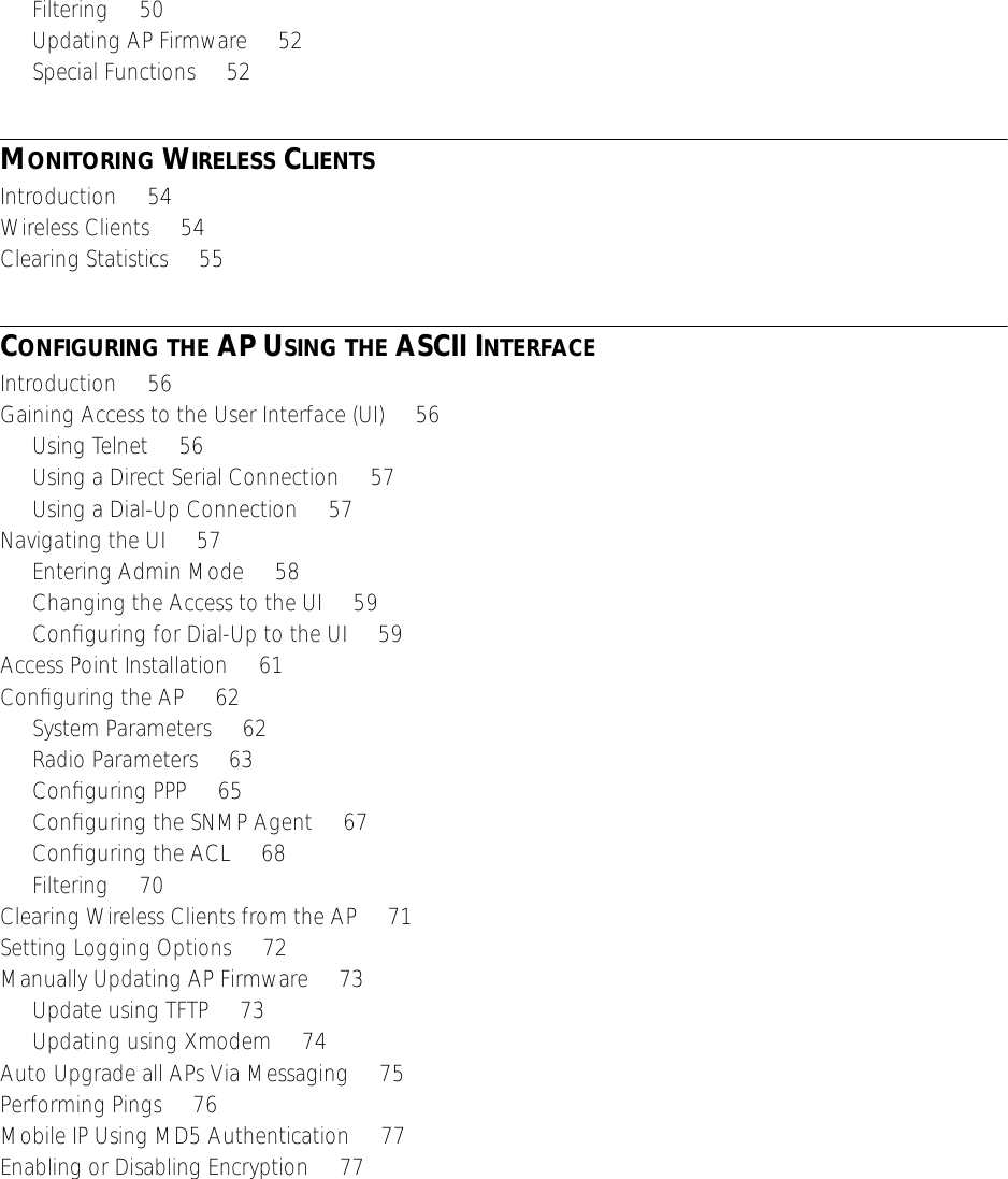
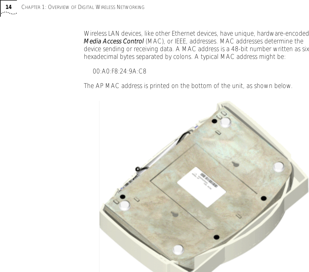
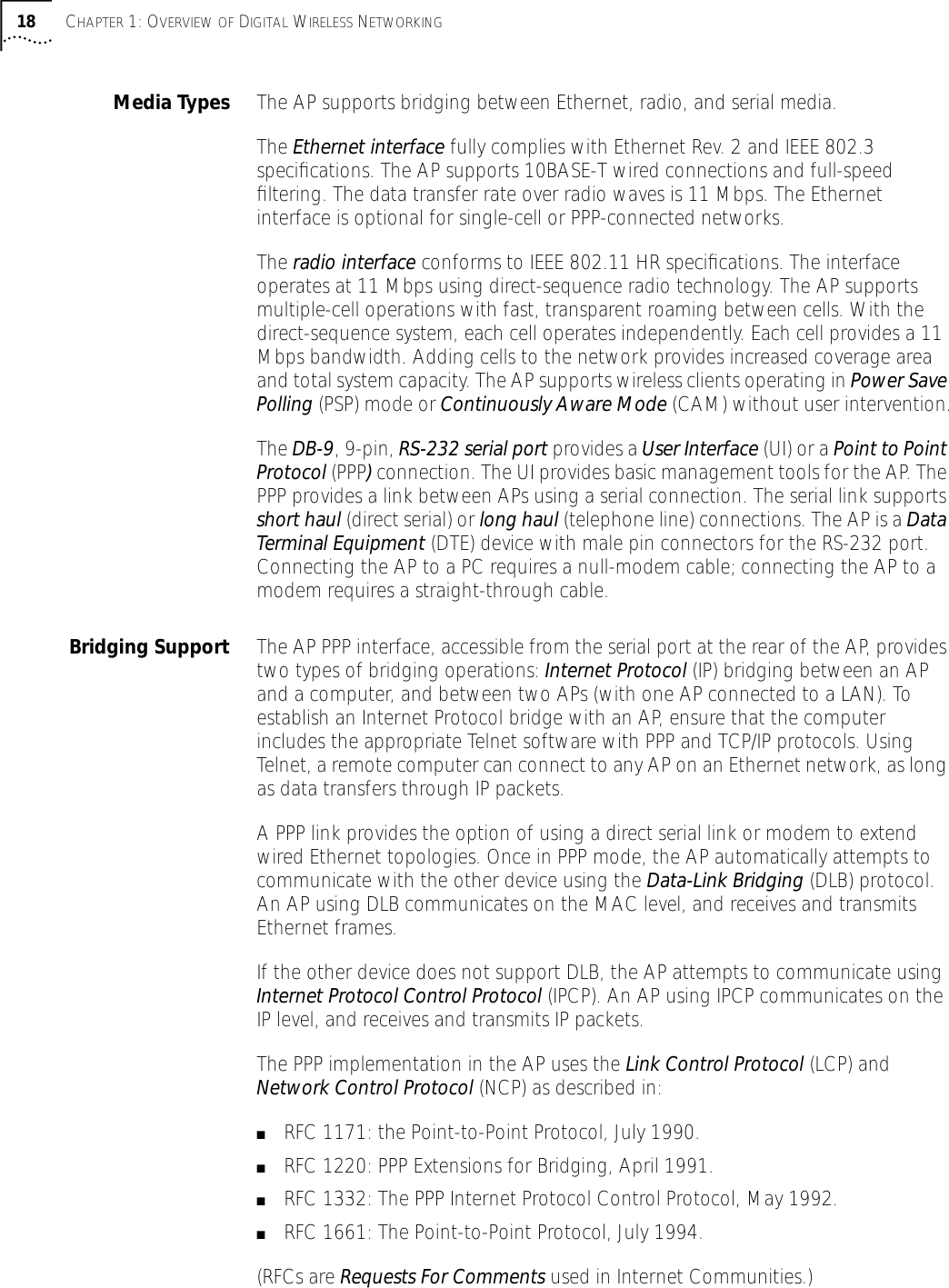
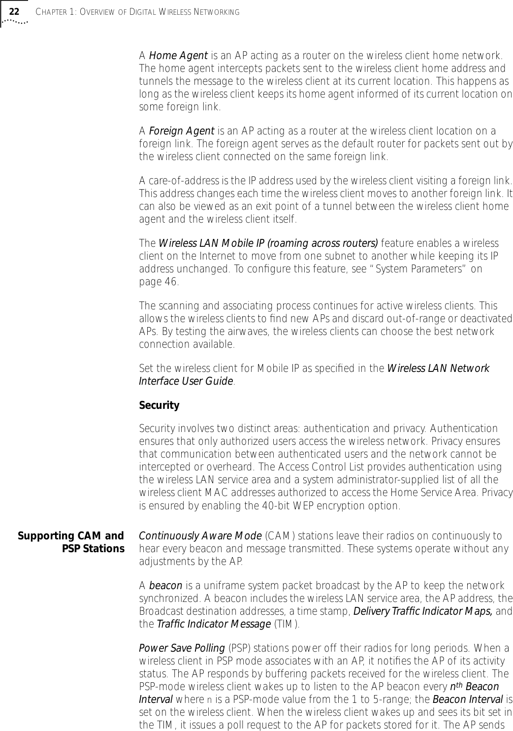
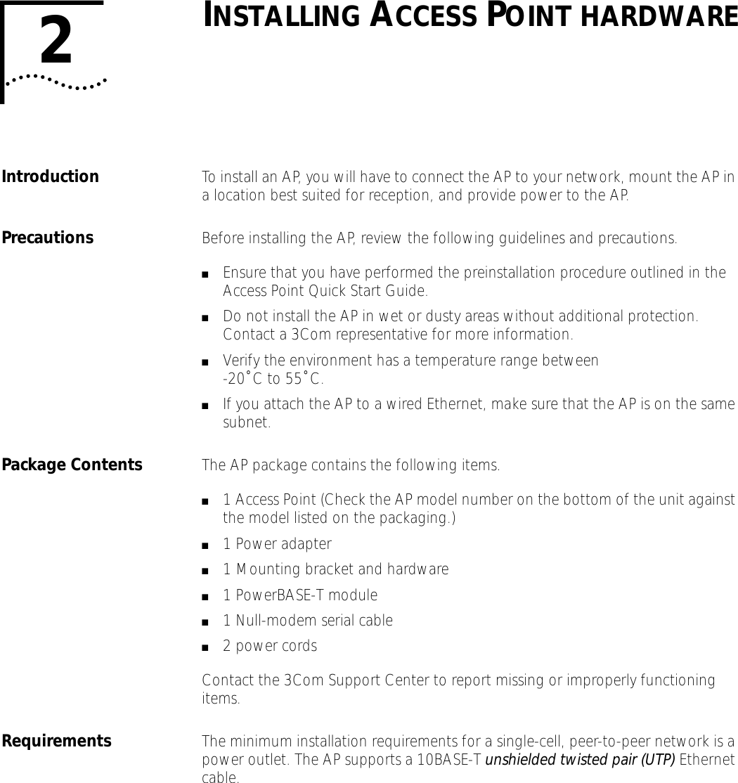
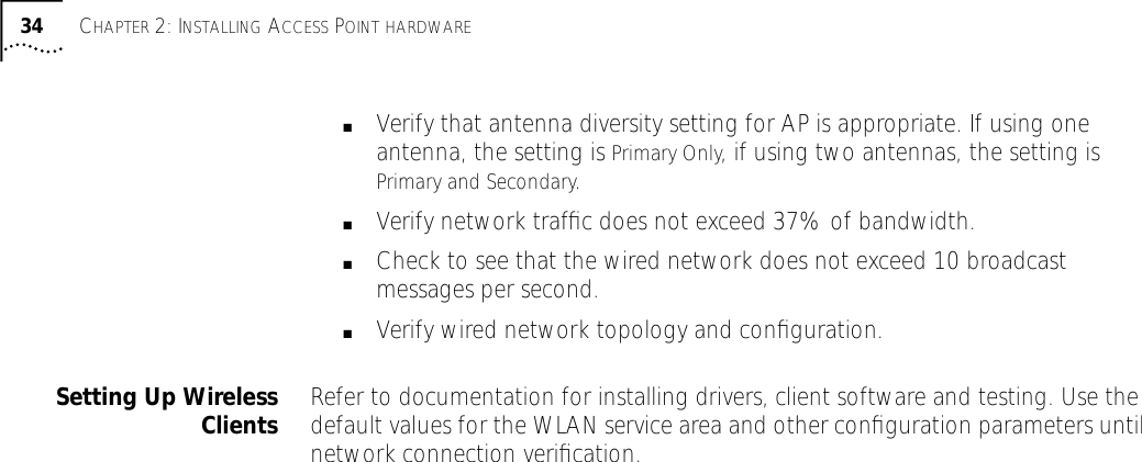
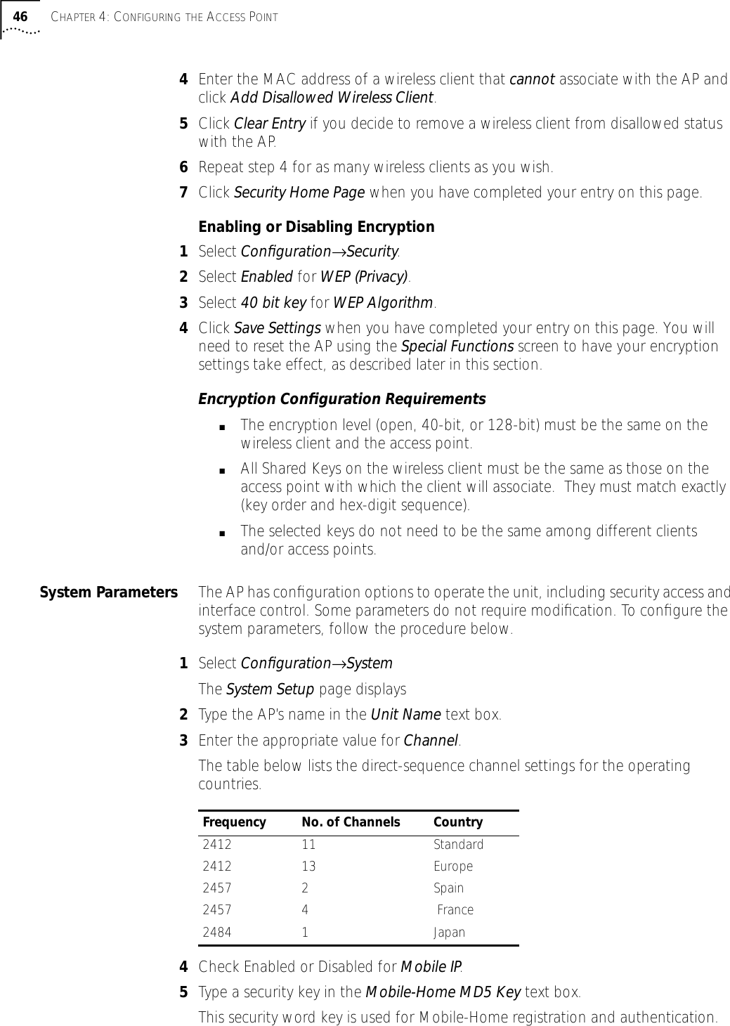
![Gaining Access to the User Interface (UI) 418Click Add to open the Directories dialog box.9Type the complete path to the directory created in step one.10 Select Virtual Directory.11 Type the folder alias (i.e., Wireless LAN Help).12 Click OK.13 Enable the Default document option.14 Type WirelessLANHelp.htm as the default document and click Apply.15 Click OK to exit the window.Setup Local Workstation Help File Access To access the Help file from a local workstation, users need to load the Help file on the hard disk. To install the Help file, run the InstallShield program.1Select Wireless LAN Firmware & Software Downloads from the disk or 3Com Web site at http://support.3com.com.2Find and click the APHTMLHelp_Install32_102.exe file. The Unpacking WAP HTML Help window displays indicating that the file is decompressing and the installation wizard is about to run. The WAP HTML Help Installation Setup dialog box displays.3Follow the on-screen instructions to install the Help file on the local workstation hard disk.To access the Help file located on the local workstation, follow the procedure below.1Click Start from the Windows Task bar.2Select Programs→3Com (or the directory name created during the installation process).3Click WAP HTML Help to launch the help file program.To exit the Help file, do the following.1Click File from the Windows menu bar.2Select Close/Exit.Accessing the Web Browser UIUsing a Web browser to gain access to the UI requires that the workstation have a TCP/IP stack and access to a Web browser. The remote station can be on the wired or wireless LAN.To verify that the Web Server option is enabled for the AP, do the following:1Access the UI using a Serial or Telnet connection.2Select System Configuration.3Verify that the Web Server option on the System Configuration dialog box is enabled.4Select Save-[F1] to save the configuration.](https://usermanual.wiki/3Com/SRWL306.Users-Manual-Revised/User-Guide-139173-Page-41.png)
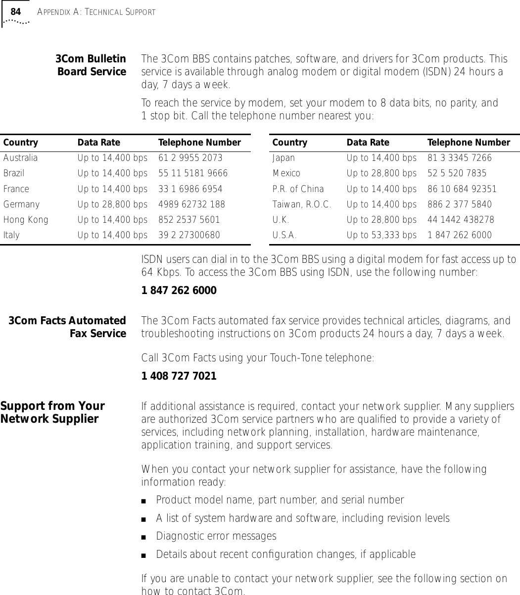
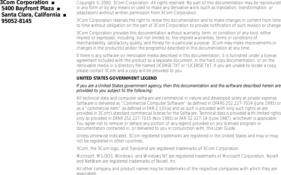
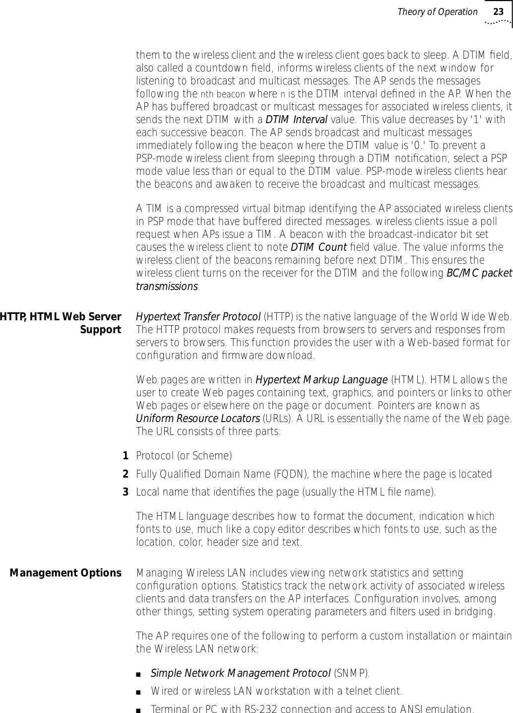
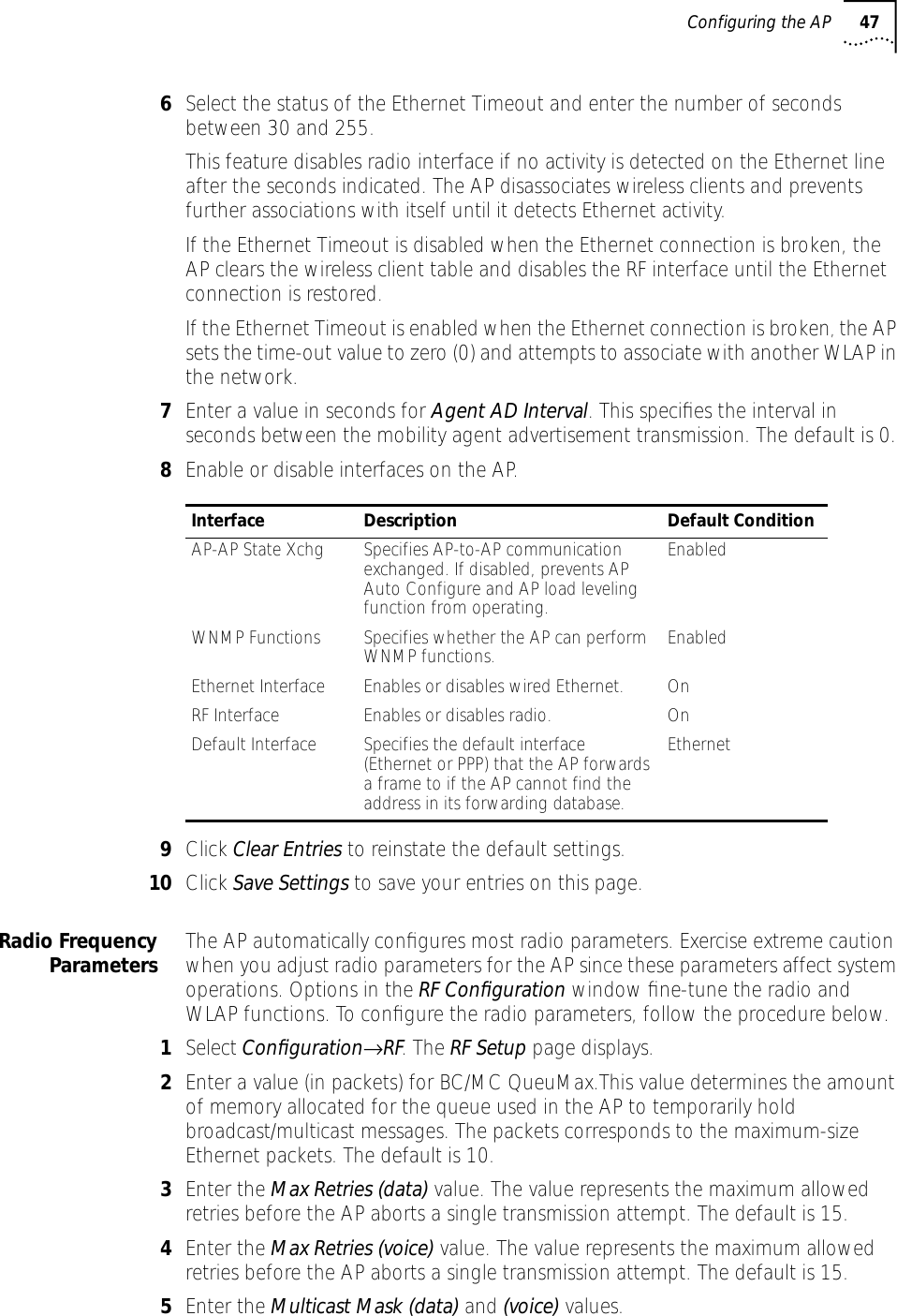
![42 CHAPTER 4: CONFIGURING THE ACCESS POINTYou must always reset the AP after you make configuration changes if you want the changes to be initiated. To reset the AP, follow the procedure below.1Select Special Functions.2Select Reset AP.3Select Yes at the confirmation prompt.To enable Help file access, change the Help URL parameter using the following procedure.1Select Special Functions.2Select Alter Filename(s)/HELP URL/TFTP Server/DHCP using Tab.3Press ENTER.4Select the .HELP URL field using the Tab key.5Type the IP address/URL (Universal Request Locator) of the Web server or the directory/folder of the Web server for the Help file location.6Press ENTER.7Select OK-[CR] using the Tab key and press ENTER.8Select the Save Configuration option to save the new setting.9Select Yes at the confirmation prompt.The Main Menu displays.10 Reset the AP for changes to take effect.To access the AP UI via a Web browser from a workstation, do the following:1Set the IP address of the workstation and the subnet mask from the NCPA properties window. The workstation, in this case, is the workstation or laptop computer running the Web browser. The informational message instructs you to reboot the system for property changes to take effect.2Ping the AP to verify the connection by typing the command below at the default DOS prompt:Ping -t xxx.xxx.xxx.xxxIf the ping receives no response, verify that the hardware connections, IP address, gateway address, and subnet mask are correct. If these items are correct, contact your network administrator for assistance.3Start your Web browser (Internet Explorer 4.0 or greater, or Netscape 3.0 or greater).4Type the IP Address for the associated AP to access that AP via the Web browser. The Wireless LAN Access Point Configuration Management System main page displays.(The Web pages look different than the Telnet, Direct Serial, or Dial-Up Connections. Access the different page types using the nodes located in the left](https://usermanual.wiki/3Com/SRWL306.Users-Manual-Revised/User-Guide-139173-Page-42.png)
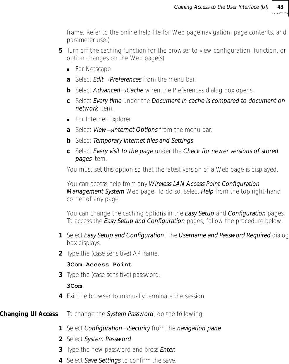
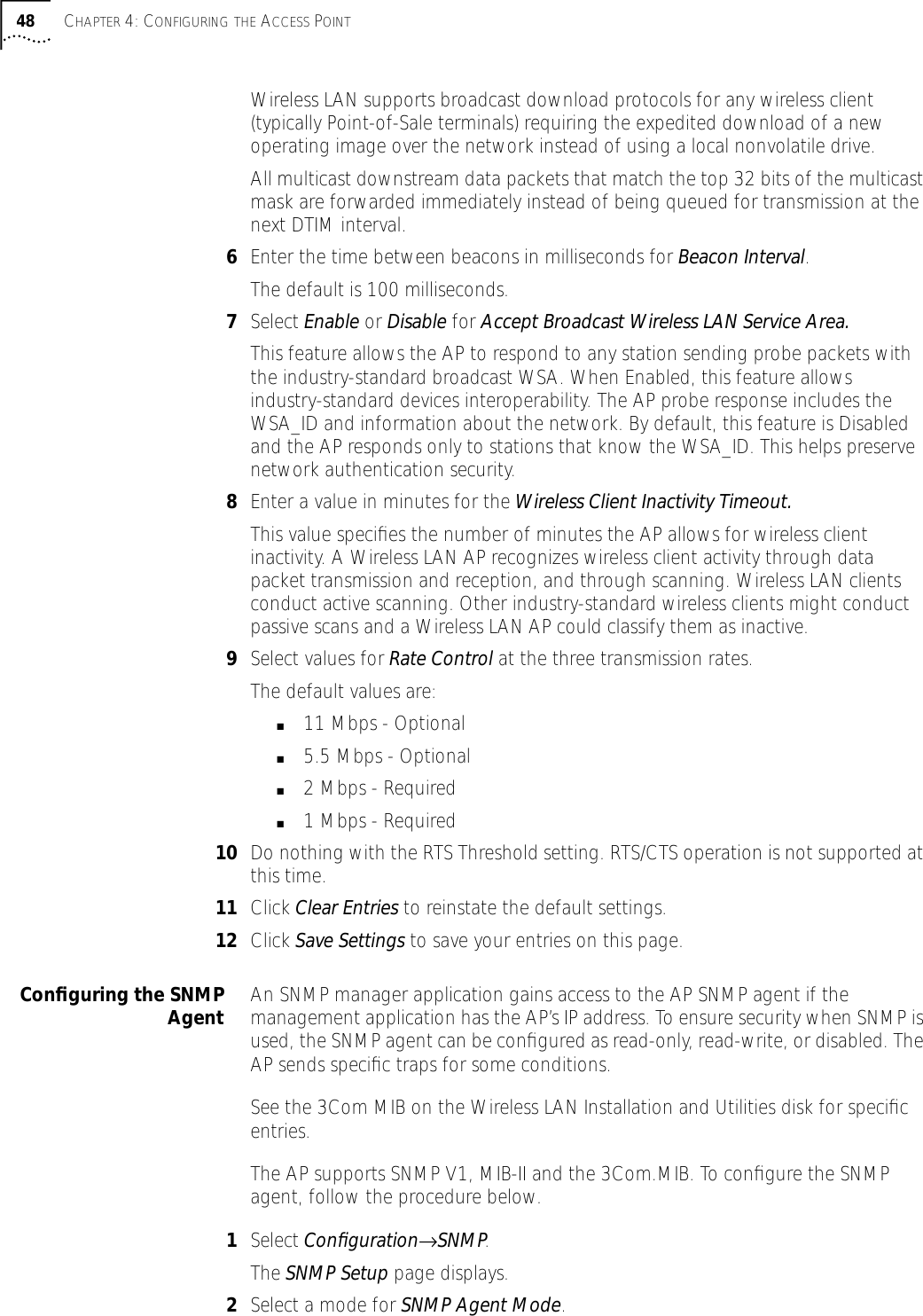
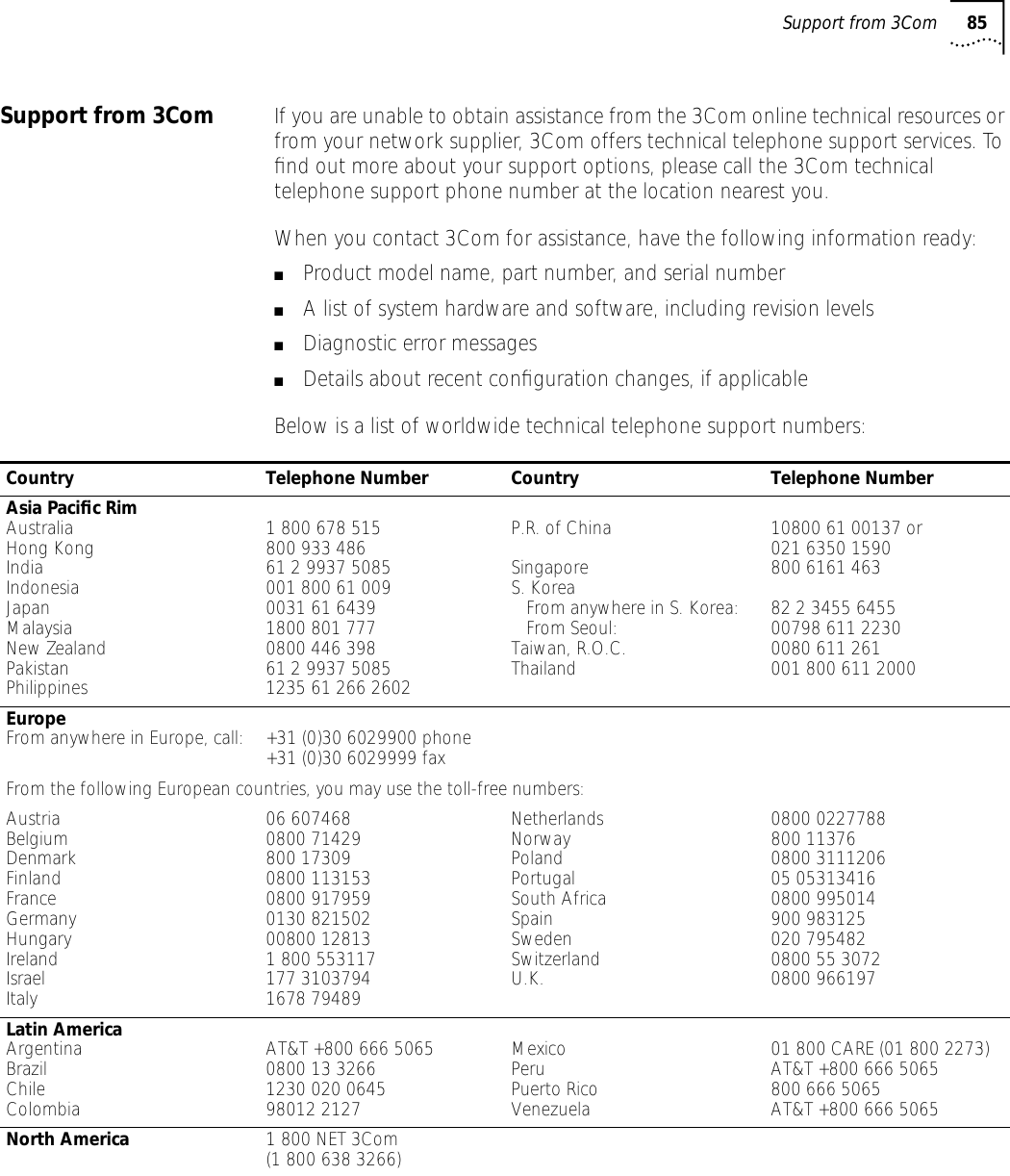
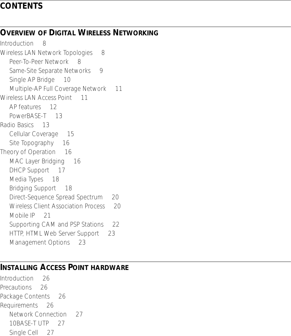
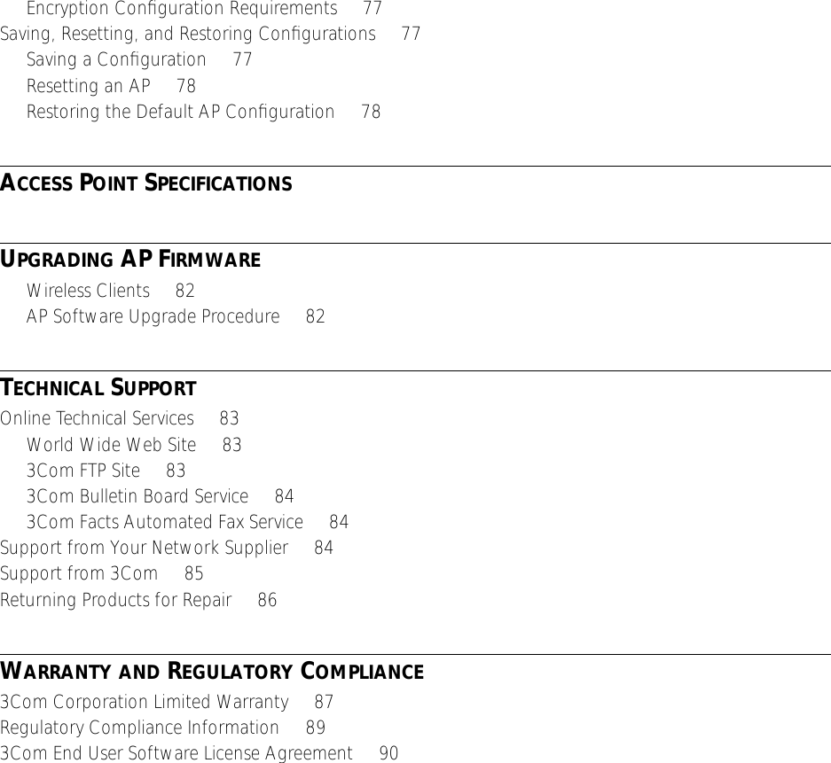
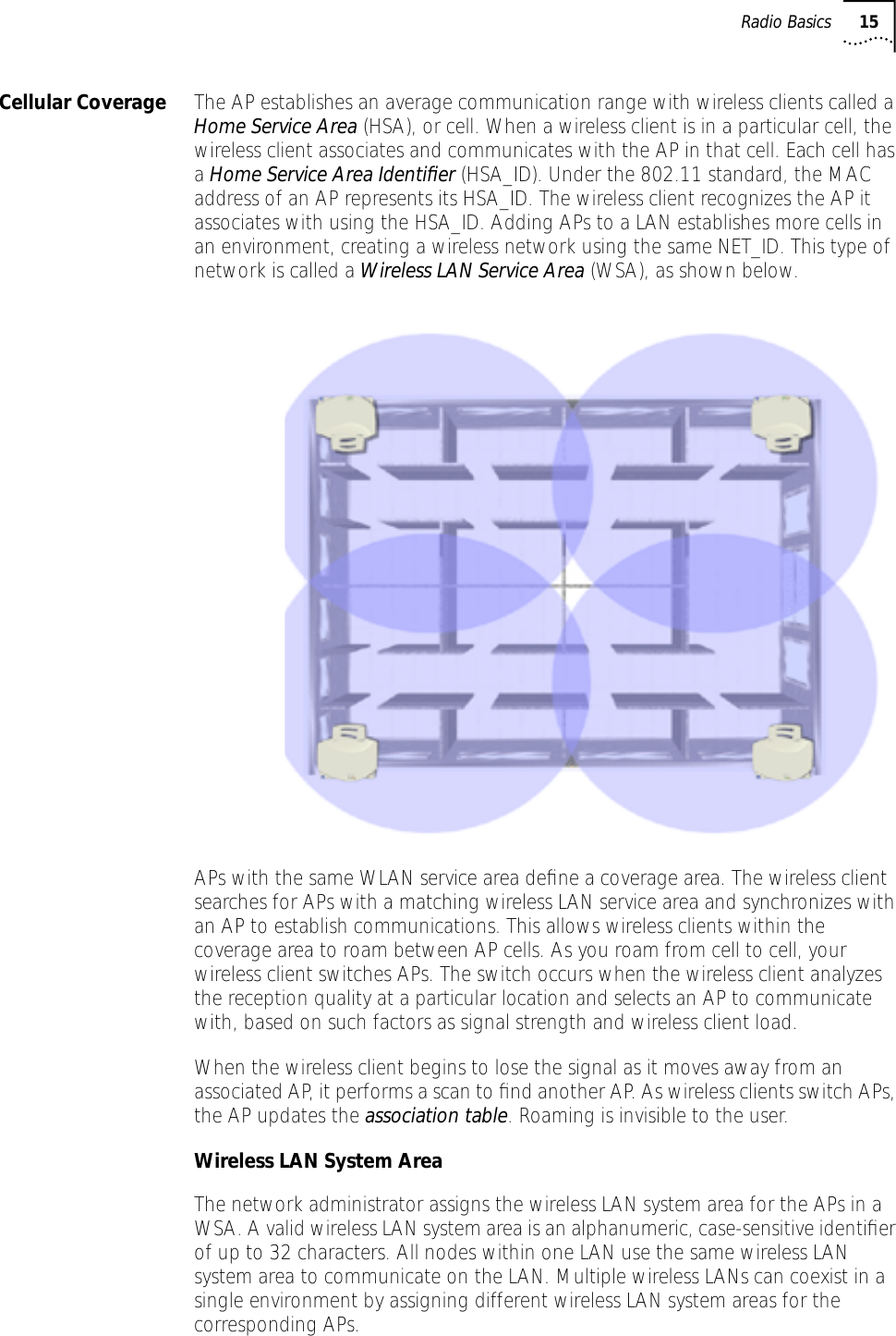
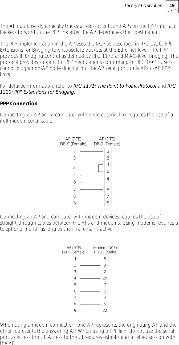
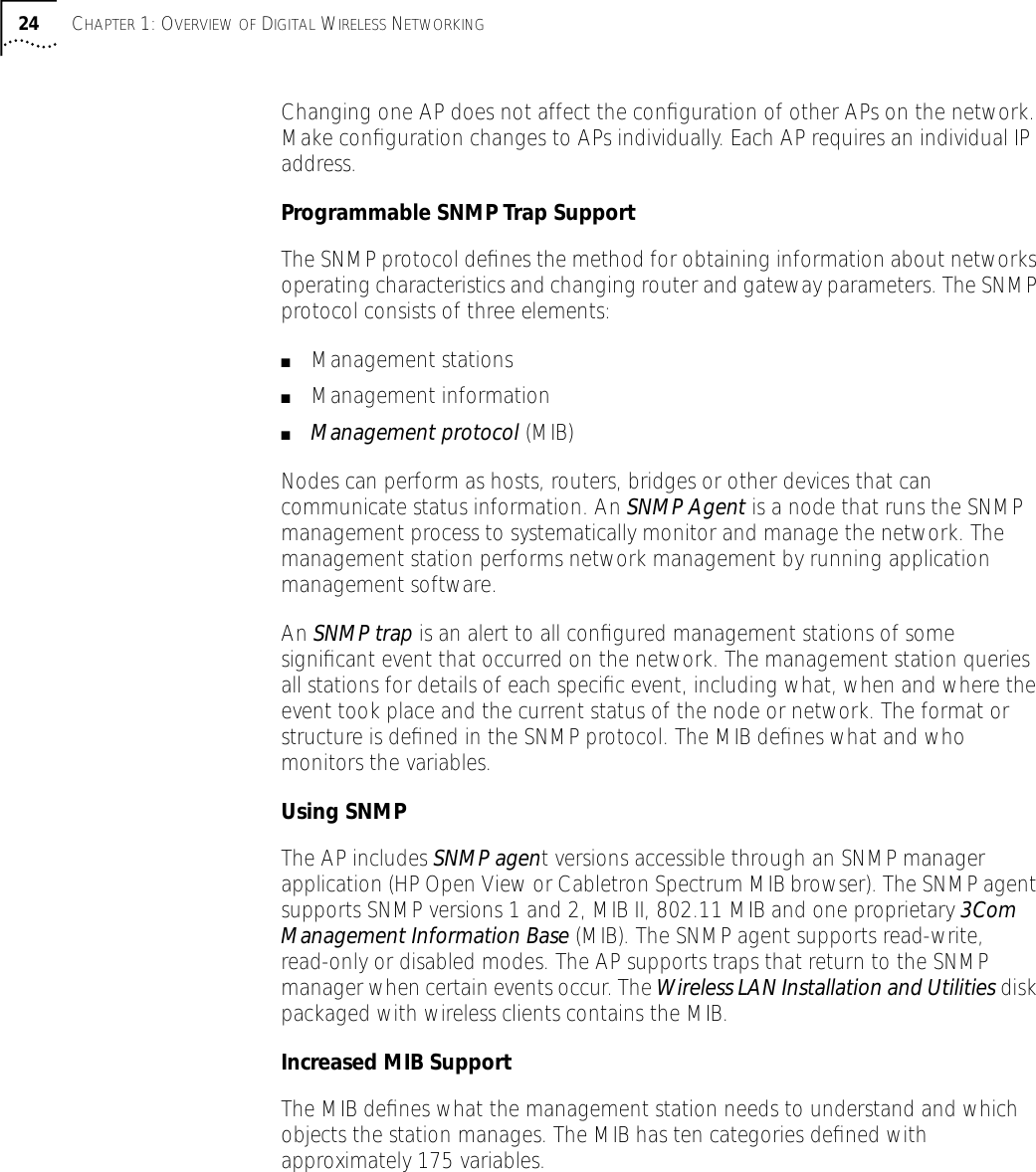
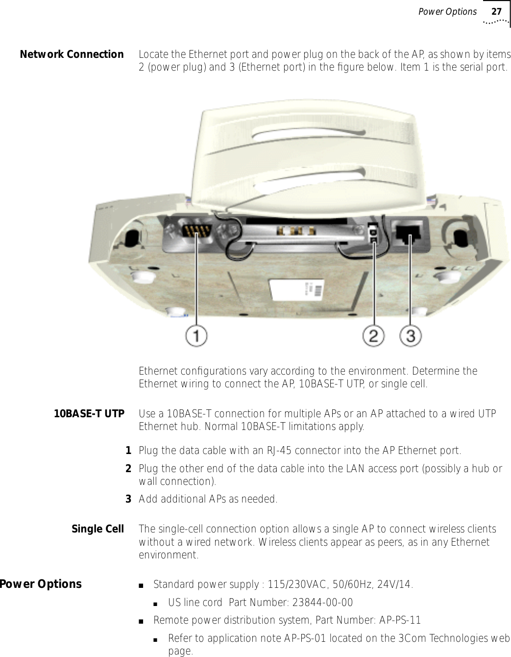
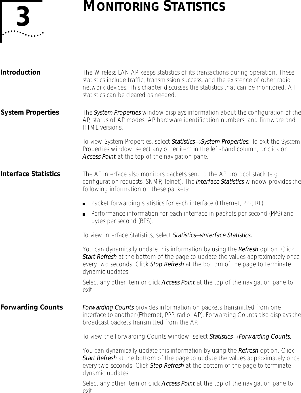
![5MONITORING WIRELESS CLIENTSIntroduction The AP keeps statistics of its transactions during operation. These statistics indicate traffic, transmission success, and the existence of other radio network devices. Clear statistics as needed.Wireless Clients Wireless Client statistics provide information on wireless clients associated with an AP. The statistics include information on data sent and received, activity and association. A wireless client shows only in the Home/Foreign Agent Table screens when the wireless client has roamed to another AP on a different subnet. Once a wireless client has roamed, the wireless client IP Address displays on the Home Agent Table screen of the wireless client’s home AP with the IP Address of the Foreign Agent to tell the “home” AP where to forward packets. The wireless client IP Address is also shown in the Foreign Agent Table and Regular screens of the new “foreign” AP to tell the new AP where to expect packets from for newly associated wireless clients. The AP Regular screen shows the wireless clients associated locally on the same subnet.1Select Wireless Client from the Main Menu.2Use the Tab or arrow keys to highlight the desired screen. 3Press Enter to display the screen you selected.4Select Regular at the Wireless Clients prompt.The display shows the currently associated wireless clients listed by MAC address. The list appears as follows: addr [p:i#:e]Variable Descriptionaddr Wireless client MAC address (xx:xx:xx:xx:xx:xx format)p Wireless clients power mode: ■P–PSP ■C–CAM. An unassociated wireless client does not display any characteri Wireless client location on AP interfaces:■R–radio, ■P–PPP.■A–associated with AP in the past, but not at time of verifying status# Current AP radio transmit rate (Mbps) for messages sent to this wireless client.V Indicates a 3Com voice-enabled device.](https://usermanual.wiki/3Com/SRWL306.Users-Manual-Revised/User-Guide-139173-Page-54.png)
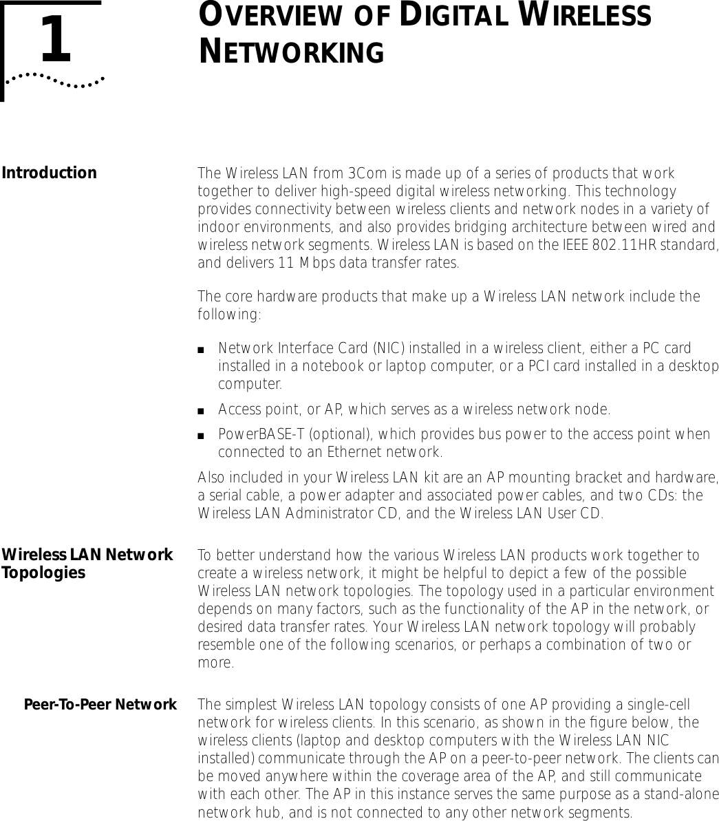
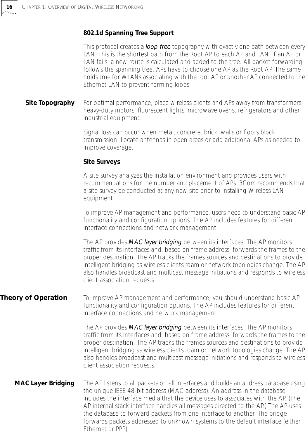
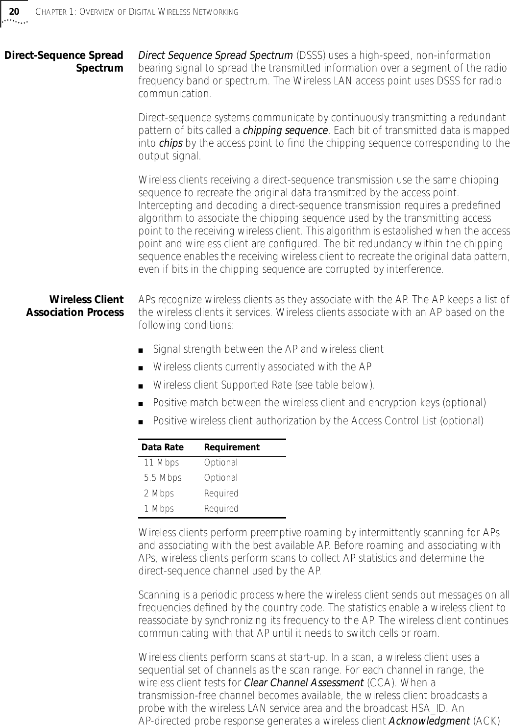
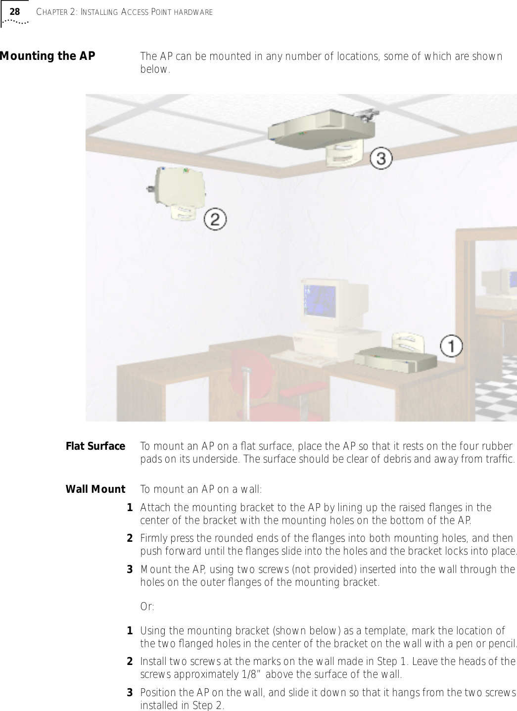
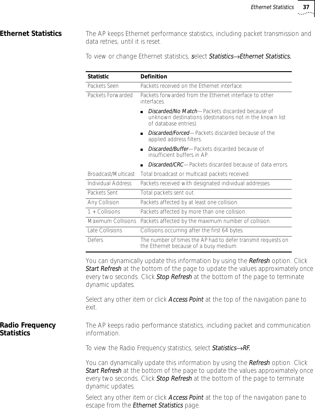
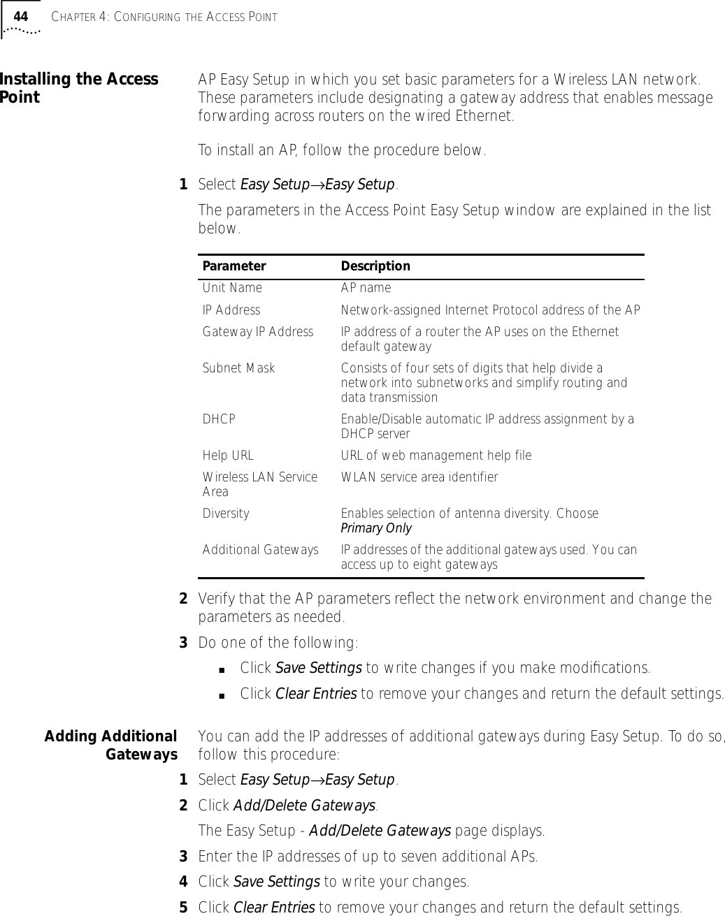
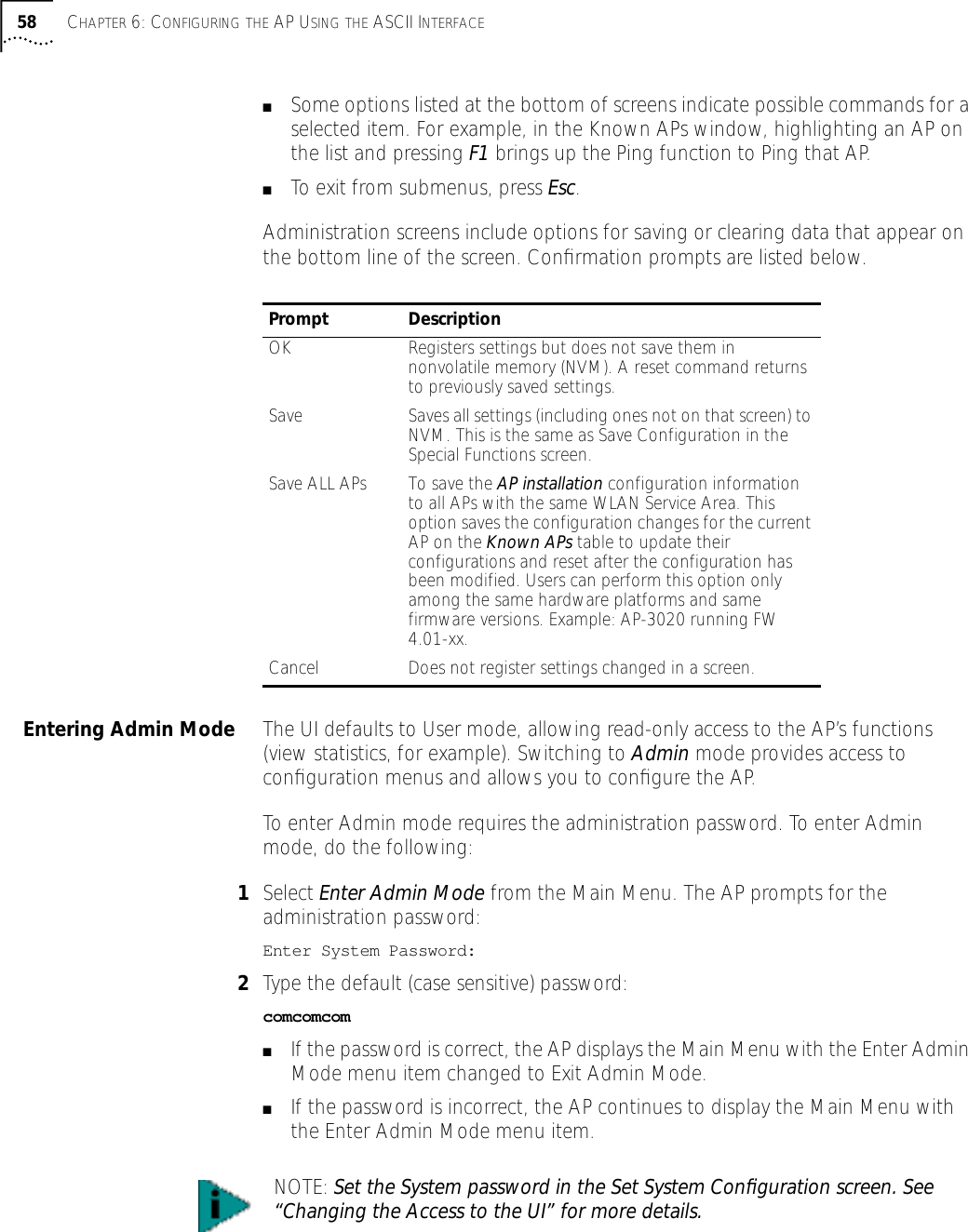
![6CONFIGURING THE AP USING THE ASCII INTERFACEIntroduction Software configuration consists of setting up a connection to the Access Point (AP) and gaining access to the User Interface (UI)..Gaining Access to the User Interface (UI) The method for establishing access to the UI depends on the connection used. Select the setup that best fits the network environment. Your connection options are:■Telnet■Direct serial connection■Dial-up connectionIf using a PPP or serial connection, access the UI through a Telnet session.Using Telnet Using a Telnet session to gain access to the UI requires that a remote station has a TCP/IP stack. The remote station can be on the wired or wireless LAN.To access the AP from the workstation, follow the procedure below.1From the DOS prompt, Telnet to the AP using its IP address:Telnet xxx.xxx.xxx.xxx2Type the appropriate password (case sensitive) at the prompt.comcomcom3Press ESC. The AP displays the Main Menu. If the session is idle (due to no input, for example) for the configured time, the session terminates. To manually terminate the session, press CTRL+D.4Select the Set System Configuration option to set the System Password.NOTE: Before configuring the AP, you may wish to upgrade the Wireless LAN firmware to the latest version. Refer to “Manually Updating AP Firmware” on page 73.NOTE: The dot in front of certain parameters, functions, or options (.Antenna Selection Primary Only) indicates these items update to all APs with the same WLAN Service Area when you select the “Upgrade ALL APs” [F2] option. This option can only be executed among the same hardware platforms and same firmware versions.](https://usermanual.wiki/3Com/SRWL306.Users-Manual-Revised/User-Guide-139173-Page-56.png)
![Navigating the UI 57Using a Direct SerialConnection To use the ASCII interface with a direct serial connection, follow the instructions in the AP Quick Start Guide, included in your package.Using a Dial-UpConnection The AP supports a dial-up connection to the UI. This requires accessing the UI from Telnet or a direct serial connection and changing the serial port configuration. Configure the AP for the following:■Enable serial port.■Set serial port for UI.■Disable any modem connection.■Set AP to answer mode.Select the Set Serial Port Configuration option to configure these settings. For details on configuring these settings, see “Configuring for Dial-Up to the UI”.Navigating the UI Use the following keystrokes to navigate through the UI menus and windows depending on the terminal emulation. For terminal emulation programs that do not support arrow or function keys, use the control-character equivalents.The following conventions also apply to navigating windows and menus:■To select menu items, press the key corresponding to the bold letter for the item (case-sensitive hot key). Press Enter to select the item.■Press Tab to scroll through menu items.■To change menu items, select items from the bottom line of the Main Menu for configuration options. For multiple choice options, press the bold letter to select. To change values, type in the new value and press Enter. If the value is invalid, the AP beeps and restores the original value. Press Tab to scroll to the next menu item.■Select an option from the bottom line on the menu to enable changes to take effect. Press Tab to scroll to the item and press Enter to select it.■When you change values, such as System Name or System Password, accept values by scrolling to the next field or pressing Enter.■You can use function keys to enable commands in some windows. For example, statistic windows include Refresh-[F1] and Timed-[F2] command/key combinations to update the display.Arrow/Function Key Control CharacterUp Arrow CTRL + ODown Arrow CTRL + ILeft Arrow CTRL + URight Arrow CTRL + PF1 CTRL + QF2 CTRL + WF3 CTRL + EF4 CTRL + R](https://usermanual.wiki/3Com/SRWL306.Users-Manual-Revised/User-Guide-139173-Page-57.png)
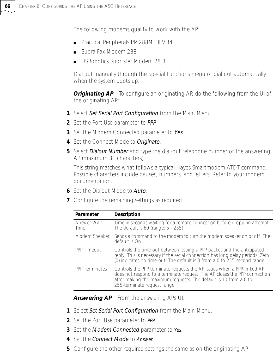
![Navigating the UI 59Changing the Access tothe UI To prevent unauthorized Telnet access, change the configuration access to the UI. This includes enabling or disabling the Telnet Logins or changing the System Password.To change Telnet access to the AP, do the following:1Select Set System Configuration from the Main Menu.2Select Telnet Logins.3Press the space bar or left/right arrow to toggle between Enabled and Disabled.4Press Tab to highlight the SAVE-[F1] function at the bottom of the screen.5Press Enter to confirm the save.To change the System Password, do the following:1Select Set System Configuration from the Main Menu.2Press Tab to select System Password.3Type the new password and press Enter.4Press Tab to highlight the SAVE-[F1] function at the bottom of the screen.5Press Enter to confirm the save.Configuring for Dial-Upto the UI A dial-up connection requires a straight-through Ethernet cable between the modem and the AP. The remote PC requires a modem and a communication program, such as HyperTerminal.The AP supports modems that use the generic Hayes Smartmodem command set. The AP uses Hayes commands and is capable of working with various modems of 19200 baud or faster. 3Com does not support modems the company has not qualified.The following modems qualify to work with the AP:■Practical Peripherals PM288MT II V.34■Supra Fax Modem 288■USRobotics Sportster Modem 28.8Configuring The Serial PortTo enable and configure the serial port connection on the AP:1Select Set Serial Port Configuration from the Main Menu.2Set the Port Use parameter to PPP.3Set the Modem Connected parameter to Yes.](https://usermanual.wiki/3Com/SRWL306.Users-Manual-Revised/User-Guide-139173-Page-59.png)
![Access Point Installation 61Access Point Installation The AP UI includes an AP Installation window in which you can set basic parameters for a Wireless LAN network. These parameters include designating a gateway address that enables message forwarding across routers on the wired Ethernet.To install an AP, follow the procedure below.1Enter Admin Mode.2Select AP Installation from the Main Menu to display the Access Point Installation window.3Verify that the AP parameters reflect the network environment and change the parameters as needed.4Press the space bar or the Left or Right Arrows to toggle between Primary Only and Primary and Secondary in the Antenna Selection field.5Do one of the following:■Select OK to register the settings. Or:■Select Save to write changes to NVM, which generates a confirmation prompt.6Select Save ALL APs [F2] to save the AP installation configuration information to all APs with the same WLAN Service Area. This option saves and updates the configuration changes for the current AP on the Known APs table. The AP is reset after the configuration has been modified. You can execute this option only among the same hardware platforms and same firmware versions.7Select Cancel-[ESC] to disregard any changes made in this window and return to the previous menu.Parameter DescriptionUnit Name AP name.IP Address Network-assigned Internet Protocol address of the AP.Gateway IP Address IP address of a router the AP uses on the Ethernet default gateway.Subnet Mask The Subnet Mask consists of four sets of digits that help divide a network into subnetworks and simplify routing and data transmission:■Sets 1 and 2—Network domain.■Set 3—Subset of hosts within a larger network.■Set 4—Individual computer.WLAN Service Area The unique, 32-character, alphanumeric, case-sensitive network identifier of the AP.Antenna Selection Enables selection of antenna diversity.Additional Gateways The IP address of the additional gateways used. You can access up to eight gateways.](https://usermanual.wiki/3Com/SRWL306.Users-Manual-Revised/User-Guide-139173-Page-61.png)

![Configuring the AP 634To enable or disable interfaces on the AP, modify the following parameters:5Verify that values reflect the network environment and change them as needed.6Do one of the following:■Select OK to register the settings.Or:■Select Save to write changes to nonvolatile memory (NVM), which generates a confirmation prompt.7Select Save ALL APs [F2] to save the RF Configuration information to all APs with the same WLAN Service Area. This option saves the configuration changes for the current AP, and sends two WNMP messages to all other APs on the Known APs table to update their configurations and reset them after the configuration has been modified. You can execute this option only among the same hardware platforms and same firmware versions.8Select Cancel-[ESC] to cancel any changes you made to this screen and return to the previous menu.Radio Parameters The AP automatically configures most radio parameters. Exercise extreme caution when adjusting radio parameters for the AP since these parameters affect system operations. Options in the RF Configuration window fine-tune the radio and WLAP functions. To configure the radio parameters, follow the procedure below.1Select Set RF Configuration from the Main Menu to display the RF Configuration window.2Configure the settings as required. The table below describes the Configuration parameters.Web Server Enables the use of a Web based browser to access the UI instead of HyperTerminal or Telnet applications. An AP Reset is required for this feature to take effect.Access Control Specifies enabling or disabling the access control feature. If enabled, the ACL (Access Control List) specifies the MAC addresses of wireless clients that can associate with this AP. The default is Disabled.Type Filtering Specifies filter type for packets received either Forward/Discard or Disabled. The default value is Disabled.WNMP Functions Specifies whether the AP can perform WNMP functions. The default value is Enabled.AP-AP State Xchg Specifies AP-to-AP communication exchanged. If Disabled prevents AP Auto Configure and AP load leveling function. The default is Enabled.Parameter DescriptionEthernet Interface Enables or disables wired Ethernet. The default value is On.PPP Interface Enables or disables serial PPP. The default value is Off.RF Interface Enables or disables radio. The default value is On.Default Interface Specifies the default interface (Ethernet or PPP) that the AP forwards a frame to if the AP cannot find the address in its forwarding database. The default interface is Ethernet.](https://usermanual.wiki/3Com/SRWL306.Users-Manual-Revised/User-Guide-139173-Page-63.png)
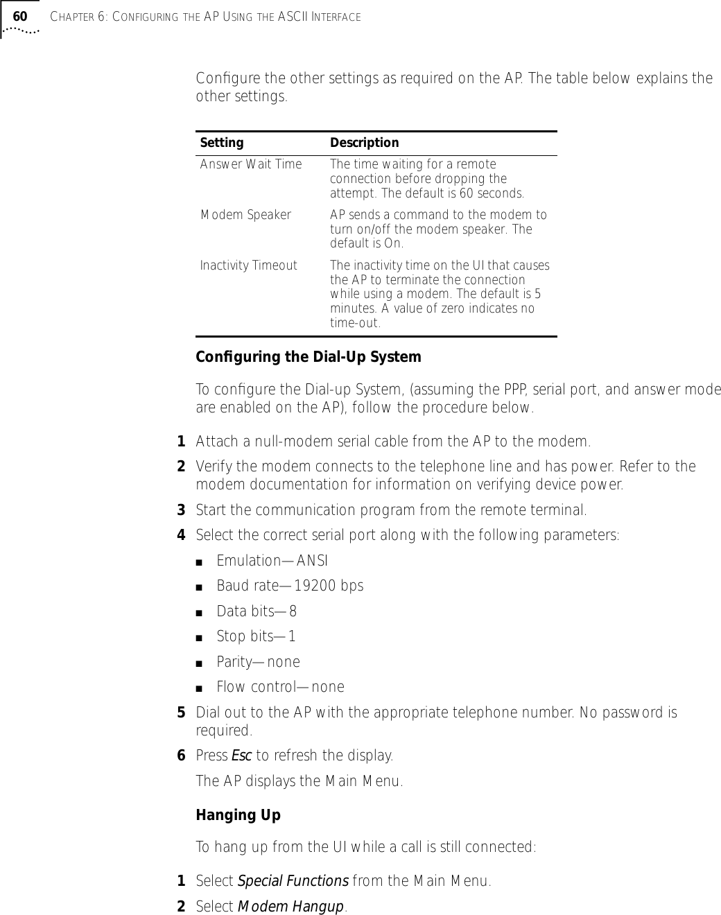
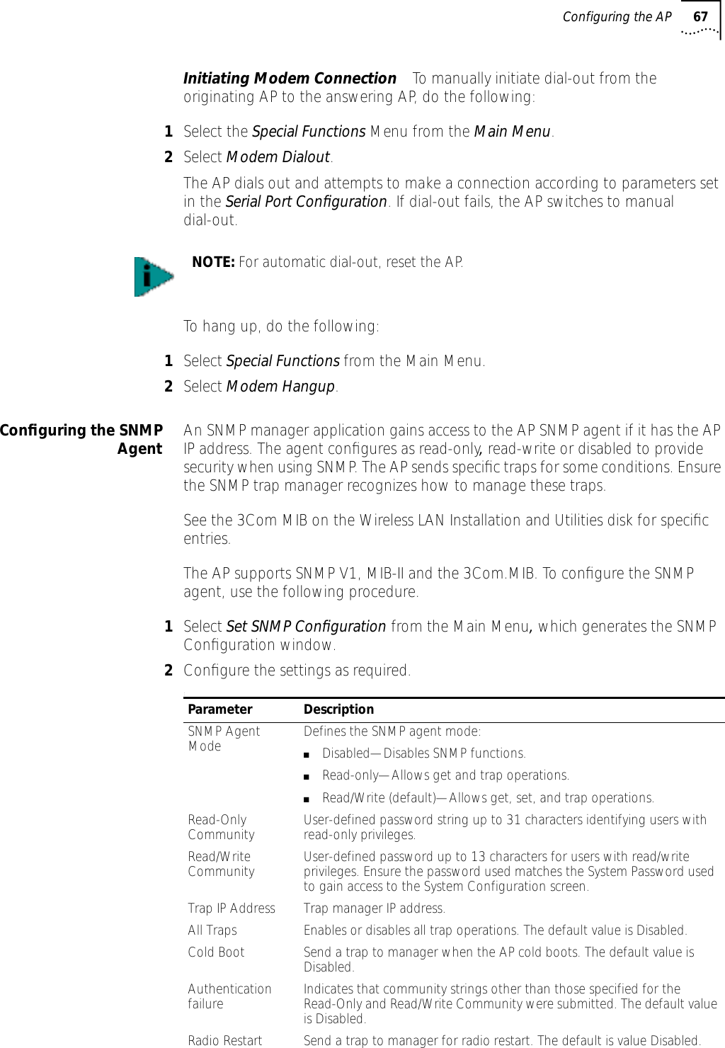
![Configuring the AP 655To save the RF Configuration information to all APs with the same WLAN Service area, select Save ALL APs [F2]. This option saves the configuration changes for the current AP, and sends two WNMP messages to all other APs on the Known APs table to update their configurations and reset them after the configuration has been modified. You can execute this option only among the same hardware platforms and same firmware versions.6Select Cancel-[ESC] to disregard any changes made to this window and return to the previous menu.Configuring PPP To use a Point-to-Point (PPP) connection, choose the appropriate hardware connection (direct or modem). Verify the enable status of the serial port) in the System Configuration menu.PPP DirectPPP direct is a direct null-modem serial cable connection between an AP and computer. To configure PPP direct, follow the procedure, below.1Select Set Serial Port Configuration from the Main Menu. The Serial Port Configuration window will be generated.2Set the Port Use parameter to UI.3Verify that the Modem Connected parameter setting is No.4Set the Connect Mode parameter to Answer.Establishing a ConnectionTo establish the PPP port connection on the AP, do the following.1Select Set System Configuration from the Main Menu.2Set the PPP Interface to OFF.3Press the space bar or left/right arrows to change the value.4Press Enter to confirm the change.PPP with ModemsThe PPP interface provides a connection using modems over a telephone line. Connect modems to the APs with null-modem (straight-through) serial cables. Designate one AP as the Originating AP and the other AP as the Answering AP. Configure the Originating AP with dial-out information to the answering AP. The answering AP waits for the originating AP to dial in to it. The AP supports modems that use the generic Hayes Smartmodem command set. The AP uses Hayes commands and is capable of working with various modems of 19200 baud or faster. 3Com does not support modems the company has not qualified.](https://usermanual.wiki/3Com/SRWL306.Users-Manual-Revised/User-Guide-139173-Page-65.png)
![68 CHAPTER 6: CONFIGURING THE AP USING THE ASCII INTERFACE3Verify that values reflect the network environment and change them as needed.4Do one of the following:■Select OK to register the settings. Or:■Select Save to write changes to NVM, which generates a confirmation prompt.5Select Save ALL APs [F2] to save the SNMP Configuration information to all APs with the same WLAN Service Area. This option saves the configuration changes for the current AP, and sends two WNMP messages to all other APs on the Known APs table to update their configurations and reset them after the configuration has been modified. You can execute this option only among the same hardware platforms and same firmware versions.6Select Cancel-[ESC] to disregard any changes made to this screen and return to the previous menu.Configuring the ACL The ACL supports adding wireless client entries by individual MAC address or by a range of MAC addresses. To select a a method of adding wireless clients, do the following:1Select Set Access Control List from the Main Menu. The prompt below displays:Address Type? range individual2Press up/down arrows to toggle between range and individual.Range of Wireless ClientsTo select a range of MAC addresses, follow the procedure below.1Type the minimum MAC address as the top value.00:0A:F8:F0:01:012Press Enter to accept the value.3Press down arrow to select the maximum value.4Type the maximum MAC address in the bottom value.00:0A:F8:F0:02:FF5Press Enter to accept the value.Access Cntrl Violation Send a trap to manager when an ACL violation occurs. The default value is Disabled.DHCP Change If enabled, this trap generates the following enterprise-specific traps:■Gateway Address Change—Indicates the gateway address for the router has changed.■IP Address Change—Indicates the IP address for the AP has changed.■IP Address Lease is up—Informs you the IP address leased from the DHCP server is about to expire.Parameter Description](https://usermanual.wiki/3Com/SRWL306.Users-Manual-Revised/User-Guide-139173-Page-68.png)
![Configuring the AP 696Press down arrow to select OK.7Press Enter. The UI generates the Ranges of Allowed Mobile Units window.8Verify that values reflect the network environment and change them as needed.9Select Delete [F1] to delete a range of Mobile Units. 10 Select Add [F2] to add a range of Mobile Units. 11 Select Save ALL APs [F3] to save the Ranges of Allowed Mobile Units information to all APs with the same WLAN Service Area. This option saves the configuration changes for the current AP, and sends two WNMP messages to all other APs on the Known APs table to update their configurations and reset them after the configuration has been modified. You can execute this option only among the same hardware platforms and firmware versions.12 Select Exit-[ESC] to return to the previous menu.When you enable the Access Control option, all wireless clients within the specified range can associate with the AP. Specify additional ranges as needed or add to the ACL using individual address entries.Adding Allowed Wireless ClientsThe Access Control List screen provides a facility to add wireless clients to the ACL. To do so, follow the procedure below.1Select Set Access Control List from the Main Menu. The prompt below displays.Address Type? range individual2Press the up/down arrows to toggle between range and individual.3Press Add [F2].The AP prompts for a MAC address.00:00:00:00:00:004Enter the MAC address. You can enter MAC addresses without colons.5Select Save ALL APs [F3] to save the AP installation configuration information to all APs with the same WLAN Service Area. This option saves the configuration changes for the current AP, and sends two WNMP messages to all other APs on the Known APs table to update their configurations and reset them after the configuration has been modified. You can execute this option only among the same hardware platforms and firmware version.Removing Allowed Wireless ClientsTo remove wireless clients, do the following:1Select the Allowed Mobile Units window.2Highlight the wireless client you want to remove using the Up or Down Arrows.3Press Delete - [F1].](https://usermanual.wiki/3Com/SRWL306.Users-Manual-Revised/User-Guide-139173-Page-69.png)
![70 CHAPTER 6: CONFIGURING THE AP USING THE ASCII INTERFACEEnable/Disable the ACLTo toggle between enable or disable, locate the ACL in the System Configuration window, then do the following:1Select Set System Configuration from the Main Menu.2Press Tab to select Access Control.3Press space bar to Enable.4Select Save to save changes.Removing All Allowed Wireless ClientsYou can remove all wireless clients from the ACL by following the procedure below.1Select Special Functions from the Main Menu.2Select Clear ACL.Load ACL from Wireless Client ListThe Load ACL from wireless client List option, from the Special Functions menu, takes all currently associated wireless clients and creates an ACL from them. This builds an ACL without you having to manually type addresses. Edit the ACL using the add and delete functions.1Select Special Functions from the Main Menu.2Select Load ACL from wireless client List to add the addresses of associated wireless clients to the ACL.Filtering The AP has two types of filtering: address filtering and type filtering. This section explains the two types of filtering and how to use them.Address FilteringThe AP can keep a list of the MAC addresses of wireless clients that are disallowed from associating with it. The Disallowed Addresses option provides security by preventing unauthorized access by known devices. Use the option for preferred association of wireless clients to APs. To filter by MAC address, follow the procedure below.1Select Set Address Filtering from the Main Menu, which generates the Disallowed Addresses list window.2View the list to determine whether you would like to add or delete addresses from the list.Adding Disallowed Wireless Clients To add wireless clients to the Disallowed Addresses list, do the following:1Select Set Address Filtering from the Main Menu.2Select Add -[F2]. The AP prompts for a MAC address.00:00:00:00:00:00](https://usermanual.wiki/3Com/SRWL306.Users-Manual-Revised/User-Guide-139173-Page-70.png)
![Clearing Wireless Clients from the AP 713Enter the appropriate MAC address. You can enter MAC addresses without colons.Removing Disallowed Wireless Clients To remove wireless clients from the Disallowed Addresses list, do the following:1Select Set Address Filtering from the Main Menu.2Highlight the MAC address using the Up or Down Arrows.3Select Delete-[F1] to delete the MAC address.Type FilteringPacket types supported for the type filtering function include the 16-bit DIX Ethernet types. The list can include up to 16 types.Adding Filter Types To add packet types to the Type Filtering list, do the following:1Select Set Type Filtering from the Main Menu.2Select Add-[F2].3Enter the packet type.Removing Filter Types To remove packet types from the Type Filtering list, do the following:1Select Set Type Filtering from the Main Menu.1Highlight the packet type by pressing up/down arrows.2Select Delete.Controlling Type Filters Set the type filters to forward or discard the types listed. To control the type filtering mode:1Select Set System Configuration from the Main Menu.2Select Type Filtering.3Press space bar to toggle between the Forward, Discard or Disable type filtering.4Press Enter to confirm your choice.5Select Save ALL APs [F2] to save the Type Filtering Setup information to all APs with the same WLAN Service Area. You can execute this option only among the same hardware platforms and firmware versions.Clearing Wireless Clients from the AP The Clear wireless client Table feature ensures that wireless clients associating with the AP are active. You should only clear the wireless client association table for diagnostic purposes, or if the AP has many wireless client associations that are no longer in use.](https://usermanual.wiki/3Com/SRWL306.Users-Manual-Revised/User-Guide-139173-Page-71.png)
![Manually Updating AP Firmware 737Select Save ALL APs [F2] to save the Event Logging Configuration information to all APs with the same WLAN Service Area. This option saves the configuration changes for the current AP, and sends two WNMP messages to all other APs on the Known APs table to update their configurations and reset them after the configuration has been modified. You can execute this option only among the same hardware platforms and firmware versions.8Select Cancel [ESC] to disregard any changes made to this screen and return to the previous menu. Manually Updating AP Firmware You have two options for manually updating the AP firmware. You can use either of the following:■A TFTP host■Any computer using the Xmodem file transfer protocol.The two files required for firmware updates are:3cap_fw.bin3cap_htm.binUpdate using TFTP The Ethernet TFTP upgrade method requires a connection between the AP and PC on the same Ethernet segment. Verify the PC has a TFTP server running on it. Running the server requires third party software such as FTP PC/TCP for DOS or OnNet™ for Windows. The wireless TFTP upgrade method requires a connection between the AP and a TFTP server. The TFTP server can be running on a 3Com Wireless LAN device.Updating the firmware requires that a TFTP server be running in the background. To update the AP firmware using TFTP, do the following:1Copy the firmware files 3cap_fw.bin and 3cap_htm.bin to the terminal or PC hard disk.2Telnet to the AP using its IP address.3Type the case-sensitive password at the prompt, which generates the Main Menu.4Select Special Functions from the Main Menu.5Select Alter Filename(s)/HELP URL/TFTP and press Enter.Type the firmware file name in the Download Filename field..6Only change this file name if you are required to do so. The default file names are 3cap_fw.bin and 3cap_htm.bin. Verify that the path to the files is accurate.7Enter the TFTP Server IP address in the TFTP Server field.8Press Enter.9Select Save Configuration to save settings.NOTE: The remainder of this procedure uses Windows 98 as an example.](https://usermanual.wiki/3Com/SRWL306.Users-Manual-Revised/User-Guide-139173-Page-73.png)
![76 CHAPTER 6: CONFIGURING THE AP USING THE ASCII INTERFACEUpdating the firmware requires that a TFTP server be running in the background. To update the AP firmware:1Copy the firmware files 3cap_fw.bin and 3cap_htm.bin to the terminal or PC hard disk.2Telnet to the AP using its IP address.3Type the case-sensitive password at the prompt (see “Changing the Access to the UI” for more details). The AP generates the Main Menu.4Select Special Functions from the Main Menu.5Select Alter Filename(s)/HELP URL/TFTP Server and press Enter.6Type the firmware file name in the Download Filename field.7Enter the TFTP Server IP address in the TFTP Server field.8Press Enter.9Select Save Configuration to save settings.10 Select Special Functions from the Main Menu.11 Select Use TFTP to Update All Access Points and press Enter, which generates the following prompt: “Are you sure (Y/N)?”12 Type y. The Telnet session ends at this point. The AP resets when the file transfer and flash programming complete.13 Telnet to the AP using its IP address.14 Type the case-sensitive password at the password prompt, which generates the Main Menu.15 Verify the accuracy of the version number in the System Summary window.16 Press Ctrl+D to end the Telnet session.Performing Pings A network node sends a ping packet to a wireless client or AP and waits for a response. Use pings to evaluate signal strength between two stations. The other station can exist on any AP interface. (This ping operates at the MAC level and not at the Internet Control Message Protocol [ICMP] level.No pings returned or fewer pings returned than sent can indicate a communication problem between the AP and the non-network station.To ping a station, follow the procedure below.1Select Show Wireless Clients from the Main Menu.2Select Regular from the Show Wireless Clients window. The Wireless Clients window generates.3Press Tab to highlight the MAC address of the station to ping.4Press the [F1] key to select Ping-[F1] This generates the Packet Ping Setup window.NOTE: Only change this file name if you are required to do so. The default file names are 3cap_fw.bin and 3cap_htm.bin. Verify that the path to the files is accurate. (See step one)](https://usermanual.wiki/3Com/SRWL306.Users-Manual-Revised/User-Guide-139173-Page-76.png)
![Mobile IP Using MD5 Authentication 775Enter the number of Pings (1 to 539), the Packet Length in bytes (1 to 539), and the Packet Data content in hex (0x00 to 0xFF).6Select Start-[CR] to begin pinging. The AP dynamically displays ping packets transmitted and received.Mobile IP Using MD5 Authentication You can achieve authentication by using the MD5 algorithm with a shared key configured into the AP and its wireless client. MD5 is a message-digest algorithm that takes an arbitrarily long message and computes a fixed-length (16 bytes) digest version of the original message. You can think of the message-digest as a unique fingerprint of the original message computed using a mathematical formula or algorithm. The message-digest is the authentication checksum of a message from a mobile wireless client to an AP during the Home Agent registration process. The MD5 algorithm prevents a wireless client from impersonating an authenticated wireless client.Enabling or Disabling Encryption The AP can be set for encryption of links to associated wireless clients. Any wireless clients associated with the AP must also have encryption enabled and set to the same level of encryption. To enable encryption in the AP, do the following:1Select Special Functions from the Main Menu.2Select Enabled for WEP (Privacy).3Select 40 bit WEP Algorithm.4Select Save to enter your selections, then answer Yes at the confirmation prompt.5Reset the AP as described below for your settings to take effect.EncryptionConfigurationRequirements■The encryption level (open, 40-bit, or 128-bit) must be the same on the wireless client and the access point.■All Shared Keys on the wireless client must be the same as those on the access point with which the client will associate. They must match exactly (key order and hex-digit sequence).■The selected keys do not need to be the same among different clients and/or access points.Saving, Resetting, and Restoring ConfigurationsThis section discusses how you can save, restore, or reset your AP configurations.Saving a Configuration The AP keeps only saved configuration changes after a reset. To make configuration changes permanent, save changes as needed. To save all changes, press F1 in all configuration screens that display the Save option. Otherwise, follow the procedure below.1Select Special Functions from the Main Menu. The Special Functions Menu is generated.2Select Save Configuration and press Enter.](https://usermanual.wiki/3Com/SRWL306.Users-Manual-Revised/User-Guide-139173-Page-77.png)