3D Robotics S111A Ready To Fly Aerial Multirotor System User Manual
3D Robotics, Inc Ready To Fly Aerial Multirotor System Users Manual
Users Manual
Operation Manual
3DR Support
We’re here to help! If you have any questions about your Solo
or if you need technical support, don’t hesitate to contact us.
online: 3dr.com/support
email: support@3dr.com
call: +1 (858) 225-1414 (direct)
+1 (855) 982-2898 (toll free in the US and Canada)
Support line hours:
Mon-Fri 8 am to 5 pm PST
Sat 9 am to 3 pm PST
3D Robotics (3DR)
1608 4th Street, Suite 410
Berkeley, CA 94710
Tel. +1 (858) 225-1414
3dr.com
Solo Operation Manual vA
DCT0077
© 2015 3D Robotics Inc.
GoPro, HERO, the GoPro logo, and the GoPro “Be a HERO” logo are
trademarks or registered trademarks of GoPro, Inc.
Contents
1 System Description 1
1.1 System Overview 1
1.2 Aircraft Overview 2
1.3 Controller Overview 3
1.4 Operating Parameters 5
1.5 Autopilot 5
1.6 Propulsion 6
1.7 Electrical System 7
1.8 Communication 8
2 Setup 9
2.1 In the Box 9
2.2 Battery 9
2.3 Controller 11
2.4 Propellers 12
2.5 Camera 13
2.6 App 14
3 Safety 16
3.1 Location 16
3.2 Environmental Awareness 16
3.3 Propellers 16
3.4 Home Position 16
3.5 Altitude & Safety Fence 17
3.6 Emergency Procedures 17
3.7 Power Management 17
3.8 Flight Battery 18
3.9 Controller 18
3.10 GPS Management 19
3.11 Signal Management 20
4 Operating Procedures 21
4.1 Preflight Checklist 21
4.2 Takeoff 21
4.3 Land 22
4.4 In-Flight Data 23
4.5 Joystick Control 24
4.6 Smart Shots 27
5 Maintenance 28
5.1 Legs 28
5.2 Motors 29
5.3 Pairing 31
6 Appendix 32
6.1 Specifications and Operating Parameters 32
6.2 Warranty 33
6.3 Regulatory Compliance 33
6.4 Sensor Data Sheets 34
Figures
Figure 1.1.1: Solo System Context Diagram 1
Figure 1.2.1: Solo Exterior Overview 2
Figure 1.2.2: Solo Interior Overview 3
Figure 1.3.1: Controller Schematic Diagram 4
Figure 1.4.1: Solo Operating Parameters & Specifications Table 5
Figure 1.5.1: Solo Onboard Sensors Table 6
Figure 1.6.1: Motor Schematic Diagram 6
Figure 1.6.2: Solo Motor Order 7
Figure 1.7.1: Solo Electrical System 7
Figure 2.1.1: Solo Parts 9
Figure 2.2.1: Charge Solo Battery 10
Figure 2.2.2: Insert Solo Battery 10
Figure 2.3.1: Charge Controller 11
Figure 2.3.2: Power On Controller 11
Figure 2.4.1: Attach Propellers 12
Figure 2.5.1: Attach Camera 13
Figure 2.5.2: Camera Configuration Process 13
Figure 2.6.1: Connect to Solo Link 14
Figure 2.6.2: Controller Preflight Update Prompt 14
Figure 2.6.3: Solo App Update Process 14
Figure 2.6.4: Controller Updating Display 15
Figure 2.6.5: Controller Update Display 15
Figure 2.6.6: Solo Update Displays 15
Figure 2.6.7: Viewing Video on the App 15
Figure 3.5.1: Controller Maximum Altitude Warning 17
Figure 3.7.1: Low controller battery warning and return-home notifications 18
Figure 3.7.2: Low flight battery warning and auto-land notifications 18
Figure 3.10.1: Controller Waiting-for-GPS Prompt 19
Figure 3.10.2: Controller GPS Lost Notification 19
Figure 3.11.1: Controller Signal Lost Warnings With GPS 20
Figure 3.11.2: Controller Signal Lost Warnings Without GPS 20
Figure 4.2.1: Controller Start Motors Prompt 21
Figure 4.2.2: Controller Auto-Takeoff Prompt 22
Figure 4.3.1: Return Home Behavior 22
Figure 4.4.1: Controller In-Flight Data Display 23
Figure 4.5.1: Controller Left Joystick 24
Figure 4.5.2: Throttle Joystick Behaviors 24
Figure 4.5.3: Yaw Joystick Behavior 25
Figure 4.5.4: Controller Right Joystick Controls 25
Figure 4.5.5: Pitch Joystick Controls 26
Figure 4.5.6: Roll Joystick Controls 26
Figure 5.1.1: Leg Replacement Process 1 28
Figure 5.1.2: Leg Replacement Process 2 28
Figure 5.1.3: Leg Replacement Process 3 29
Figure 5.2.1: Motor Pod Replacement Process 1 29
Figure 5.2.2: Motor Pod Replacement Process 2 30
Figure 5.2.3: Motor Pod Replacement Process 3 30
Figure 5.2.4: Motor Pod Replacement Process 4 30
Figure 5.2.5: Motor Pod Replacement Process 5 31
Figure 5.3.1: Solo Pair Button 31
Figure 5.3.2: Controller Pairing Process 31

1
1 System Description
Solo is a reliable, easy-to-use quadcopter optimized for capturing aerial video and still imagery. This section
provides a technical description for the 3DR Solo system, including components, communication, control, telemetry,
and operator interaction.
1.1 System Overview
The 3DR Solo system includes the Solo quadcopter, Solo controller, “3DR Solo” app, and the human operator.
The operator interacts with the controller and app on the ground, and the controller communicates with the Solo
quadcopter during flight.
The 3DR Solo system includes the Solo quadcopter, controller, “3DR Solo” app, and the human operator. The
operator interacts with the controller and app on the ground, and the controller communicates with the Solo
quadcopter during flight.
Solo Quadcopter
Solo is a small unmanned aerial vehicle powered by four brushless motors and four propellers. Solo’s onboard
computers control navigation, attitude, and communications in flight while sending real-time telemetry and video
output and receiving control inputs over the 3DR Link secure WiFi network. Solo is optimized for aerial imagery
using a GoPro® HERO camera.
Controller
The controller provides joystick, button, and dial controls and displays in-flight data on a full-color screen. Using
twin long-range dipole antennae, the controller acts as the central hub for all communication on the 3DR Link
network, receiving all communications from Solo and the app, forwarding telemetry outputs to the app, and
controlling the transmission of all control inputs to Solo.
App
The “3DR Solo” app outputs a live video stream from Solo’s onboard camera to an Android or iOS device. The
operator can use the app to view the live video with overlaid telemetry and access a simplified graphic interface for
controlling Solo’s advanced functions. The app connects to the 3DR Link network to receive video and telemetry
outputs and send control inputs.
Figure 1.1.1: Solo System Context Diagram
Video output
Telemetry output
Control input
Operator
3DR Solo
Controller
3DR Solo
3DR Solo
App
AirGround
3DR Link
Secure WiFi
Network
2
1.2 Aircraft Overview
Smart Battery
The battery connects to Solo’s battery bay. Solo’s power button is located on the battery; Solo can only be powered
when the battery is connected.
Motors and Propellers
Solo’s arms are labelled one through four on the ends of the arms. Motors on arms #1 and #2 spin counterclockwise
and use clockwise-tightening propellers with silver tops. Conversely, motors on arms #3 and #4 spin clockwise and
use clockwise-tightening propellers with black tops.
Orientation LEDs
Each arm contains an LED for ground-to-air directional awareness; the two front arms (#1 and #3) display white, and
the two rear arms (#2 and #4) annunciate red. This LED scheme mimics the headlight and taillight style of a car for
easy association by any operator.
Fixed Camera Mount and HDMI Cable
Solo includes a GoPro® The Frame fixed mount to mount a GoPro® HERO camera. The HDMI cable connects to
the GoPro® to output video and charge the camera during flight.
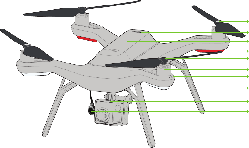
Figure 1.2.1: Solo Exterior Overview
Solo Mainboard
The Solo mainboard connects all components onboard Solo. It acts as a voltage regulator and power distribution
system for the vehicle, sending power to all components and receiving voltage and current monitoring information
from the Solo Smart Battery.
3DR Pixhawk 2
The Pixhawk autopilot handles all attitude estimation, inertial navigation, and failsafe monitoring for Solo. It receives
data from internal sensors, the external GPS module, the external compass module, and 3DR Solo Link to calculate
Solo’s in-flight dynamics. Pixhawk outputs telemetry data to the 3DR Link network and send control commands to
Solo’s four electronic speed controllers. Pixhawk sends and receives all signal through the mainboard.
Silver-top propeller
Power button
Battery
Rear orientation LEDs
Black-top propeller
Motor
Arm numbering
Front orientation LEDs
Fixed camera mount
HDMI cable
Height: 10.2”
Motor-to-motor: 18.1”
Weight (no camera): 3.3 lbs.

3
Compass Module
The compass module is placed in leg #4 to avoid interference from other electronic components. Data from the
compass is sent to Pixhawk through the mainboard for use in attitude estimation.
GPS Module
The GPS module is located in front of the battery in a copper-shielded enclosure to reduce interference. GPS data is
essential for Solo’s automated flight capabilities. The GPS module sends data to Pixhawk through the mainboard.
Electronic Speed Controllers
Solo contains four electronic speed controllers (ESCs) to manage control of each of the four motors. ESCs receive
commands from Pixhawk through the mainboard and regulate the rotation of the motors to achieve the correct flight
speeds.
3DR Solo Link
The 3DR Solo Link module manages communication between Solo and the controller on the 3DR Link secure WiFi
network. 3DR Solo Link receives all control inputs, outputs telemetry, and outputs video signals to communicate
with the ground over the 3DR Link network. 3DR Solo Link also runs software processes regulating advanced
automated functions and data conversion. This module sends and receives data from Pixhawk through the
mainboard.
Antennas
Twin dipole antenna in the legs #1 and #2 send and receive signals from the 3DR Link WiFi network.
Figure 1.2.2: Solo Interior Overview
1.3 Controller Overview
Mobile-Device Holder
Mount an Android or iOS device to run the Solo app and effortlessly integrate the app into the controller’s operation
flow.
1
ESC
GPS
Mainboard
Compass
Antenna
4
Joysticks
The controller’s left and right joysticks provide direct manual control of Solo and physical control mechanisms for
using automated Smart Shots.
Screen
The controller’s full-color screen provides prompts for correct operation of Solo, live in-flight data, and control over
automated Smart Shots.
Power Button
The power button provides a quick check of the controller’s power level when pressed once and powers on the
controller when held. The controller provides vibration feedback to indicate that the power-up is successful.
Fly Button
The fly button lets you control Solo’s main flight functions: starting motors, auto-takeoff, auto-land, and activating
manual flight.
Return Home
The return-home button allows you to end your flight automatically at any point by returning Solo to its original
launch point and landing.
Pause Button
The pause bottom is Solo’s emergency air brake. Press pause to stop Solo and hover in place.
Option Buttons
The A and B buttons change functionality based on where you are in the operational flow. The screen will show
the currently assigned functions of A and B at all times. You can program A and B to specific functions using the
controller.
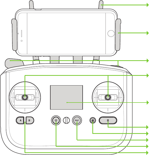
Figure 1.3.1: Controller Schematic Diagram
Antennae
Mobile-device holder
Gimbal controls
Joysticks
Screen
Pause
Return home
Fly
Power
Options
5
1.4 Operating Parameters
The operating parameters in Figure 1.4.1 apply to Solo. Always operate Solo within these parameters. Solo’s
performance and behaviors are not guaranteed when conditions violate the parameters listed below.
Figure 1.4.1: Solo Operating Parameters & Specifications Table
*Flight time varies with payload, wind conditions, elevation, temperature, humidity, flying style,
and pilot skill. Listed flight time applies to elevations less than 2,000 ft above sea level.
1.5 Autopilot
Solo uses a Pixhawk 2 autopilot running APM:Copter 3.3-dev software. APM:Copter is open-source flight control
based on the MAVlink communication protocol and part of the ArduPilot project. Pixhawk 2 runs an ARM Cortex-M4
STM32F427 processor with 2 MB of flash memory and 256 KB of RAM. Combined with an array of CAN, I2C, SPI,
PWM, and UART interfaces, Pixhawk 2 uses a suite of onboard sensors to calculate Solo’s orientation and motion in
flight. This data is input into APM:Copter’s inertial navigation and position estimation algorithms and combined with
control inputs to send commands to Solo’s propulsion system.
Communication frequency 2.4 GHz
Estimated flight time 25 minutes*
Maximum altitude 400 ft.
Range 2,000 ft. from launch point
Payload capacity 1.1 lbs.
Cruise speed 5 kts (2.5 m/s)
Maximum speed 55 mph (24.5 m/s)
Maximum climb rate 11 mph (4.9 m/s)
Maximum descent rate 6 mph (2.6 m/s)
Headwind limitation 17 mph (7.7 m/s)
Crosswind limitation 17 mph (7.7 m/s)
Operating temperature 32 F - 113 F
Operating relative humidity 0-85% RH
Max altitude above sea level 10,000 ft.
6
Figure 1.5.1: Solo Onboard Sensors Table
*Links to data sheets for sensors listed in this table are location in Appendix 6.4.
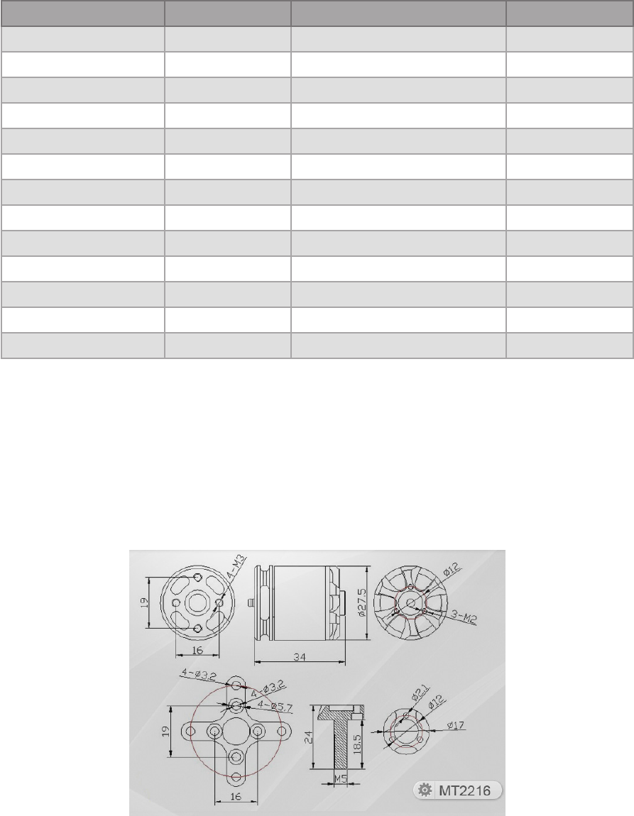
1.6 Propulsion
Solo uses four brushless, 880 KV motors and four propellers for propulsion. For control and aerodynamic efficiency,
two motors spin clockwise and two motors spin counterclockwise. Navigation in the air is achieved by mixing
propulsion of the four motors to actuate flight control along the roll, pitch, and yaw axes.
Figure 1.6.1: Motor Schematic Diagram
Location Sensor Manufacturer / Part Number* Data Type
Pixhawk 2 FMU Accelerometer InvenSense / MPU6000 Orientation
Pixhawk 2 FMU Gyroscope InvenSense / MPU6000 Motion
Pixhawk 2 FMU Magnetometer Honeywell / HMC 5983 Cardinal direction
Pixhawk 2 FMU Barometer Measurement Specialties / MS5611 Altitude
Pixhawk 2 Stabilized IMU Accelerometer InvenSense / MPU6000 Orientation
Pixhawk 2 Stabilized IMU Gyroscope InvenSense / MPU6000 Motion
Pixhawk 2 Stabilized IMU Barometer Measurement Specialties / MS5611 Altitude
Pixhawk 2 Stabilized IMU Accelerometer STMicroelectronics / LSM303D Orientation
Pixhawk 2 Stabilized IMU Magnetometer STMicroelectronics / LSM303D Cardinal direction
Pixhawk 2 Stabilized IMU Gyroscope STMicroelectronics / L3GD20 Motion
3DR Solo GPS GPS u-blox / NEO-7N Longitude & latitude
3DR Solo GPS GPS patch antenna Taoglas / GP.1575.25.4.A.02 Longitude & latitude
3DR Solo Compass Magnetometer Honeywell / HMC 5983 Cardinal direction

7
Each of the four motors is numbered by the marking on the arm. These numbers correspond to the autopilot
calculations for these commands and are used for indicating motor replacement procedures. Each motor is
controlled by an Electronic Speed Controller (ESC) that regulates the rotation of the motors to achieve the speed
commanded by the autopilot.
Figure 1.6.2: Solo Motor Order
1.7 Electrical System
Battery
Solo’s onboard electrical system is powered by a rechargeable lithium polymer battery. The battery communicates
over I2C with the Solo mainboard to report information about it’s current voltage. This information is pushed over
the telemetry output to the operator to provide data for in-flight power management and battery failsafe.
Mainboard
The Solo mainboard passes regulated voltage to the computing components onboard Solo: Pixhawk 2, 3DR
Solo Link, 3DR Solo GPS, and 3DR Solo Compass. These components have a two-way serial signal link with the
mainboard to transfer data between them via the mainboard as a central hub. The LEDs on each arm of Solo are
components of the ESCs and receive power and I2C signals via the ESCs.
Figure 1.7.1: Solo Electrical System
03 01
02 04
Pixhawk 2
ESC 1
ESC 2
ESC 3
ESC 4
Motor 1
LiPo Battery
LED 1
Motor 2
LED 2
Motor 3
LED 3
Motor 4
LED 4
3DR Solo
Link
3DR Solo
GPS
3DR Solo
Compass
Solo
Mainboard
Solo Electrical System
Serial signal
I2C signal
PWM signal
Battery voltage
Regulated voltage
8
Controller
The controller is powered by a rechargeable lithium ion battery. The controller mainboard monitors the battery’s
voltage and passes regulated voltage to the other components of the controller. 3DR Controller Link, the LED
screen, and the controller’s input devices (buttons, dials, and joysticks) receive regulated voltage from the battery
via the mainboard. The data signals between the mainboard and the components are one-way with the exception of
3DR Controller Link, which communicates with the mainboard over a two-way serial link
1.8 Communication
To communicate with the operator, Solo runs three communication flows: joystick control input, video output, and
control input/telemetry output.
Controls
The operator can initiate control inputs from the controller or the app. On the controller, the mainboard receives
inputs from the joysticks, buttons, and dials and converts them to MAVlink commands. The mainboard sends the
MAVlink commands to 3DR Controller Link for transmission to Solo over the 3DR Link WiFi network. When initiated
from the app, control inputs are sent from the app over the 3DR Link network and received by 3DR Controller Link
which re-transmits the inputs to Solo over the 3DR Link network. The redirection of controls from the app is due to
the improved range of the controller’s antennas. Solo receives the controls through 3DR Solo Link and transfers to
the data to Pixhawk via the Solo mainboard.
Smart Shots
Solo’s Smart Shots are autonomous flight patterns that make it easy to create aerial video. Smart Shots allow the
operator to choose points of interest in 3D space and fly specific patterns in relation to those points. The operator
can control Smart Shots from either the controller or the app. When using the controller with Smart Shots, the
joysticks are re-mapped to restrict Solo’s movement within the limitations of the Smart Shot. On the app, touch-
screen controls provide the same functionality as the joysticks. To Smart Shot control inputs and telemetry outputs,
the Shot Manager software module runs on 3DR Solo Link and regulates all control inputs to ensure compatibility
with any active Smart Shots.
Telemetry Output
Telemetry data from Solo is pushed from Pixhawk to 3DR Solo Link via the mainboard and transmitted to the
controller over the 3DR Link network. On the controller, 3DR Controller Link receives the outputs, translates the
MAVlink commands, and displays the live values on the controller’s screen. To transmit data to the app, 3DR
Controller Link forwards the data to the app through the 3DR Link network.

9
2 Setup
This sections covers everything you need to set up Solo out of the box.
2.1 In the Box
Solo includes the quadcopter vehicle, controller, propellers (four plus two spares), Solo charger, and controller
charger.
Figure 2.1.1: Solo Parts
2.2 Battery
Solo is powered by the rechargeable Solo Smart Battery that provides approximately 25 minutes of flight time per
full charge. (Keep in mind that flight time depends on payload, wind conditions, elevation, temperature, humidity,
flying style and pilot skill, so the actual flight time may vary.) As a lithium polymer battery, the Solo Smart Battery
requires specific handling practices to ensure safe operation and prevent accidents. For more information about
battery safety, see section 20.
Charging
The level of the battery is indicated by the lights below the power button. Press the power button once to display
the current power level. The Solo battery ships with approximately 50% charge, so charge fully before your first
flight for maximum flight time.
Remove the battery from Solo before charging. Only charge the battery using the designated Solo charger; using a
different charger can damage the battery or cause a fire. Charge the battery in conditions between 32° F and 113° F
only.
To charge the battery, connect the Solo charger to the battery and a wall outlet. While charging, the indicator lights
pulse at the current level, and when fully charged, the lights turn off. There is an additional indicator on the battery
charger that turns from red to green when the battery is fully charged. The battery takes approximately 1.5 hours to
charge fully.
Solo Three silver-top props
& three black-top props
Controller
Solo charger
Controller charger

10
Figure 2.2.1: Charge Solo Battery
Powering
To power Solo, insert the battery into Solo’s battery bay and slide the battery forward until it clicks into place. Press
and hold the battery power button to turn on Solo. When Solo power on, the battery will display an LED animation
and you will hear the startup tone. Only power Solo using the designated 3DR Solo Smart Battery; using a different
battery can permanently damage Solo.
Figure 2.2.2: Insert Solo Battery
Charge indicator
Charge indicator
Make sure Solo is level before powering on and keep Solo still during
power up and while the sensors initialize. Moving Solo during this
process causes the sensors to calibrate incorrectly and can create a
preflight error or affect in-flight performance.
11
2.3 Controller
The rechargeable lithium ion (Li-ion) controller battery is housed inside the controller, accessible by the battery door
at the back of the controller. The controller battery is pre-attached to the controller, and shouldn’t be disconnected
unless:
• You plan to store the controller for over three months without using it. In this case, disconnect the battery
from the controller and leave the battery inside the controller to store it.
• You need to switch the controller battery for a new or upgraded controller battery. Upgraded controller
batteries with double the capacity are available from store.3dr.com. In the case where you need to store the
extra controller battery, store it in location where it will not come into contact with metal objects or other
batteries. If the battery’s connector comes into contact with a metal object, it can short circuit the battery and
cause a fire.
Charging
Only charge the controller using the designated controller charger; using a different charger can damage the
controller or cause a fire. Charge the controller in conditions between 32° F and 113° F only.
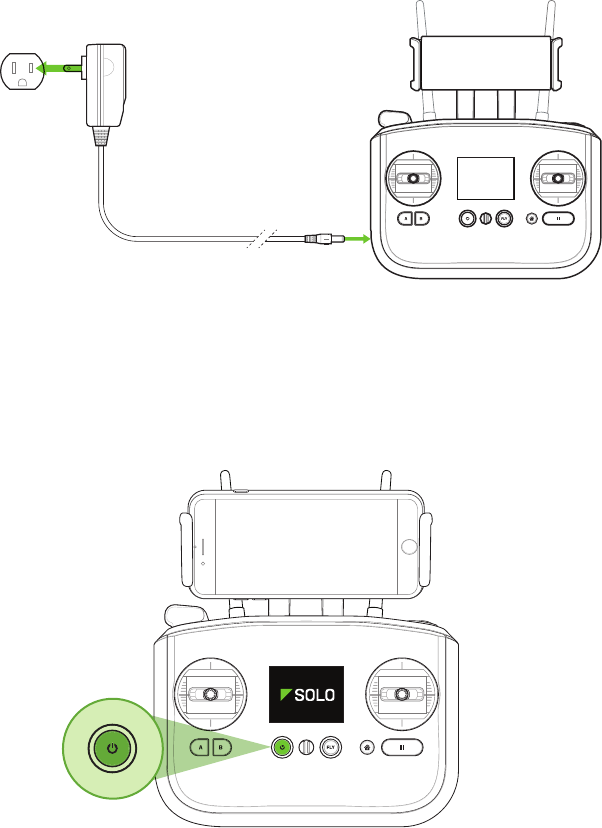
To charge the controller, connect the controller charger to the barrel jack on the side of the controller and to a
wall outlet. To check the battery level of the controller, press the power button. A fully charged controller lasts for
approximately 6 hours. Always check the controller’s battery level before you fly, and recharge when prompted by
the controller. The controller takes approximately 3 hours to charge fully.
Figure 2.3.1: Charge Controller
Powering
To power on the controller, press and hold the controller power button until you receive the vibration feedback and
see the startup screen.
Figure 2.3.2: Power On Controller
12
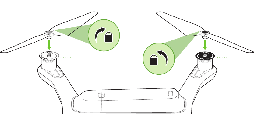
2.4 Propellers
Solo uses two types of self-tightening propellers, indicated by the color of the circle at the center of the propeller.
Attaching
Attach the propellers with silver tops to the motors with a silver dot on the top of the motor shaft, and attach the
black-top propellers to the motors with the black dots. Make sure to remove the paper labels from the motors
before attaching the propellers.
Silver-top propellers tighten clockwise; black-top propellers tighten counterclockwise. Check the lock and unlock
icons on each propeller to see the correct directions for tightening and removing.
Figure 2.4.1: Attach Propellers
remove motor labelsremove motor labels
13
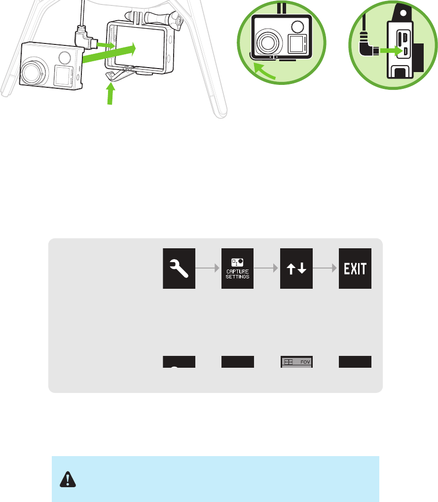
2.5 Camera
Solo includes a fixed GoPro® The Frame™ mount for your GoPro® HERO 3, 3+ or 4.
Attaching
To attach the camera to the GoPro® The Frame™ fixed mount, insert your GoPro® upside down and connect the
Solo HDMI cable to the camera.
Figure 2.5.1: Attach Camera
Settings
For best results, adjust the camera settings for inverted orientation and medium field of view. (Setting the field of
view to medium ensures that you won’t see the propellers in the frame.)
Figure 2.5.2: Camera Configuration Process
Make sure that the Wi-Fi on your GoPro® is turned OFF. It can
interfere with Solo’s communication signals and cause unexpected
behavior.
GoPro® The Frame™
Your GoPro®
HERO 3, 3+ or 4
Mount your GoPro®
upside down. Connect the HDMI
cable.
Set the GoPro® to
inverted orientation:
Set the GoPro® to
medium field of view:
GoPro®
Settings
GoPro®
Settings
Camera
Orientation

14
2.6 App
“3DR Solo” provides a streaming video link to a mobile device and provides a simple graphic interface for
interacting with Smart Shots and other advanced Solo features.
Install
Visit 3dr.com/soloapp or download “3DR Solo” from the App Store or Google Play Store. 3DR Solo works with iOS
8.0 or later and Android 4.1.2 (Jelly Bean) or later.
Connect to Solo
To connect the app to the 3DR Link WiFi network, access the WiFi settings on the mobile device and select Solo_
Link-####. Enter the temporary password “sololink”. Once connected, return to the app to continue.
Figure 2.6.1: Connect to Solo Link
Update
Before your first flight, perform the required first-flight update for Solo and the controller using the app. The
controller will prompt you for the update with the screen shown in Figure 2.6.2.
Figure 2.6.2: Controller Preflight Update Prompt
To complete the update, open the app and select the settings menu in the top-left corner. Select Software Update
to begin the update process. Use a fully charged Solo battery, ensure that both the controller and Solo are powered,
and the app will automatically update the system wirelessly.
Figure 2.6.3: Solo App Update Process
Settings
Airplane Mode
WI-FI
Bluetooth
Cellular
Solo_Link-####
On
Notifications
Control Center
Do Not Disturb
7:34 PMLTE
General
Sounds
Wallpapers & Brightness
Privacy
15
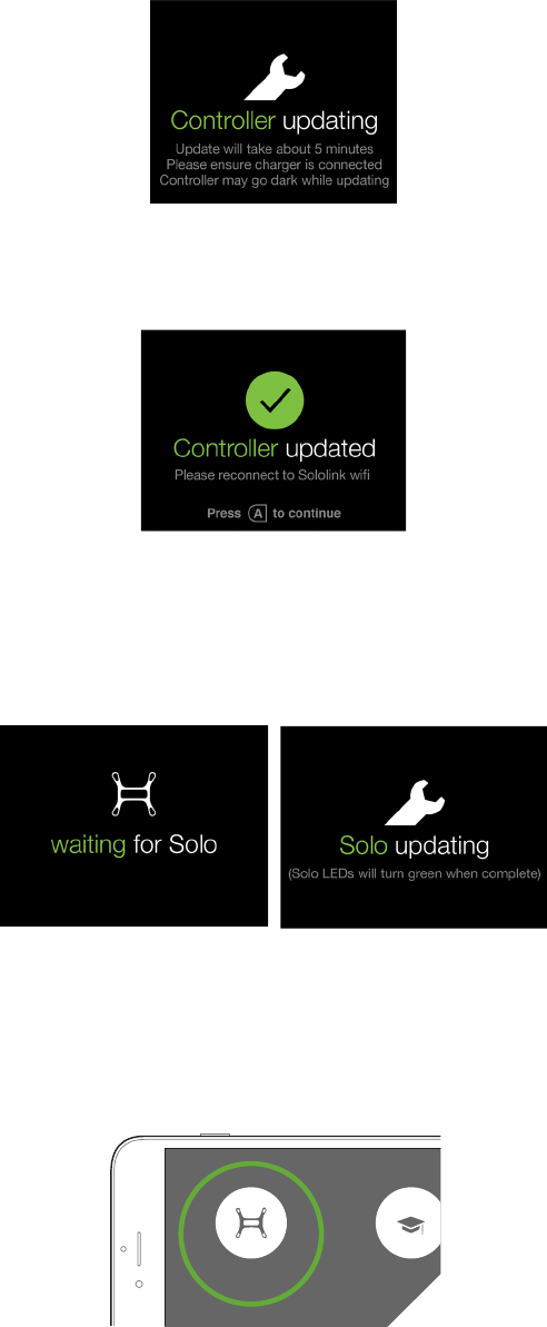
Ensure that the controller is connected to the charger during the update process. While the update is in progress,
the controller will show the screen shown in Figure 2.6.4. The controller may complete a restart as part of the update
process.
Figure 2.6.4: Controller Updating Display
When the controller update is complete, the controller will display the screen shown in Figure 2.6.5. Press A to
continue the update.
Figure 2.6.5: Controller Update Display
After pressing A, Solo will update. The controller will display waiting for Solo and Solo updating (Figure 2.6.6) while
the update is in progress. When the update is complete, Solo’s LEDs will display green and the controller will return
to the standard startup screen.
Figure 2.6.6: Solo Update Displays
View Video
After the update is complete, select Fly Solo to view video. Solo, the controller, and the GoPro® must be powered
to view video. Verify that you can view video before your first flight.
Figure 2.6.7: Viewing Video on the App
Rusty Mitchell Support
FLIGHT SCHOOL
SOLO VIDEO

16
3 Safety
The following best practices will help to ensure safe, successful flights and reduce the risk of accident and serious
injury.
3.1 Location
Don’t fly Solo indoors. Always fly in clear, open areas at a safe distance from yourself, other people, power lines,
animals, vehicles, trees, and buildings. When flying in areas with potential hazards, maintain 100 feet from any
people, vehicles, or structures. As the operator, you are responsible for navigating Solo to avoid obstacles, including
during automated flight.
Don’t fly within 5 miles of an airport or anywhere pilots operate manned aircraft, or within any airspace restricted by
your local, state or national airspace authority. As the operator, you are responsible for knowing and understanding
the regulations that govern small unmanned aircraft like Solo in your jurisdiction.
3.2 Environmental Awareness
Before flying, determine the boundaries of the safe flying area at your flying location. Be aware of any risks at your
location, including bodies of water, structures, trees, etc. Designate a few areas as safety zones where you can
safely land the copter in case of an unsafe situation. Throughout your flight, be prepared to recover Solo manually if
it goes outside the safe flying area.
Don’t fly Solo in extreme weather conditions such as rain, high winds, snow or fog. Environmental factors and GPS
irregularities can cause instability in flight, and this can affect Solo’s performance or cause an in-flight failure.
3.3 Propellers
When prompted to start motors before takeoff, always ensure that the propellers are clear of any obstructions and
away from any people, animals, or property before activating. Do not touch moving propellers or approach Solo
while the propeller are spinning. Always hold the fly button to stop the motors before approaching Solo.
After an auto-landing or return home, Solo will automatically detect the landing and stop the motors. Do not
approach Solo until the propellers stop spinning. After a manual landing, hold the throttle (left joystick) to the
bottom-left corner to stop the motors.
3.4 Home Position
Abstractly, Solo’s home position is the latitude and longitude coordinates of the launch point used by the autopilot
as the end point of a return home command. In practice, the autopilot saves the home position at the location where
the motors are started only after achieving GPS lock. If Solo does not acquire GPS lock before starting the motors,
no home position will be saved and the return-to-home feature will be unavailable.
Read and understand these important safety instructions before your
first flight to help reduce the risk of accident and serious injury.
Spinning propellers can cause serious injury. Never touch moving
propellers or place any objects in the way of the propeller arcs.
400 ft
400 ft

17
3.5 Altitude & Safety Fence
Fly at appropriate altitudes for your flying location and local regulations. Solo cannot avoid obstacles on its own, so
always select altitudes that avoid any obstacles, such as trees, buildings, and other tall structures.
Solo includes a 400-foot safety fence enabled by default. This altitude reflects current FAA regulations to avoid
potential conflicts with manned aircraft and represents a safe line-of-sight altitude. If Solo reached the maximum
altitude, it will stop ascending and limit throttle input to stay below 400 feet. In this case, the display shown in Figure
3.5.1 will be displayed to the user to inform them to fly at a lower altitude.
Figure 3.5.1: Controller Maximum Altitude Warning
3.6 Emergency Procedures
If Solo exhibits instability in flight or flies outside your designated safe flying area, perform one of Solo’s emergency
recovery procedures to land safely.
Pause
The controller’s pause button allows you to stop Solo mid-air. Solo will hover at the paused location until given
another command. Use the pause button to stop Solo before hitting an obstacle or to re-orient Solo for navigation.
Regain Manual Control
During Smart Shots and other autonomous behaviors, keep the controller easily accessible, and be prepared to
regain manual control at any time. To regain manual control during Smart Shots, press the fly button.
Return Home
If Solo acquired GPS lock prior to takeoff, press the controller’s home button to return Solo to the launch point and
land. Use return home after receiving a low battery notification or to end your flight easily.
Land
To land Solo at its current position, press and hold the fly button. Solo will land immediately at the current position.
If Solo does not have GPS lock, there will be no automatic position as Solo descends and drifting may occur
depending on environmental conditions.
3.7 Power Management
The controller monitors the level of the controller battery and the Solo battery in flight. If either battery reaches low
levels during flight, the controller announces the low battery state and provides an instruction to end your flight and
recharge the battery. If the controller battery reaches a critical level during flight, Solo automatically returns to home.
If the Solo flight battery reaches a critical level, Solo automatically lands to prevent a crash.
IN-FLIGHT ALERTS
Maximum Altitude
User is told that maximum altitude has been reached
Vehicle is not able to go higher than max altitude
Alert persists until:
TIMEOUT: 5000 milliseconds
Maximum altitude
Solo has reached preset
maximum altitude
Crash Detected
User is prompted to use app to log a support ticket
Alert persists until:
User presses A
Crash detected
Use 3DR Solo app to
log a support ticket
GPS signal lost (Switches to FLY: Manual)
Alert persists until:
TIMEOUT: 3000 milliseconds
GPS lost
Switching to manual control
Shot list and Return to Home
are not available
GPS signal recovered (Switches to FLY: Manual)
Alert persists until:
TIMEOUT: 3000 milliseconds
GPS recovered
Press FLY to set home location
Press to dismiss
FLY
Press to take control

18
Figure 3.7.1: Low controller battery warning and return-home notifications
Figure 3.7.2: Low flight battery warning and auto-land notifications
3.8 Flight Battery
Use caution when handling the Solo Smart Battery; there is a risk of fire if the battery is handled roughly enough
to damage it. Never alter, puncture, throw, bend or impact the battery. Keep the battery away from liquids, fire,
microwaves, and other hazardous or combustible materials. Don’t expose the battery to extreme temperatures. The
battery functions optimally when used in -4° F to 140° F; operating Solo at the extremes of this range can affect its
performance. If the battery is hot to the touch, wait for it to cool before using or charging.
Inspect the battery before and after each flight. It is possible for the battery to be damaged in shipping, use or
charging. If you notice any abnormal features such as damage to the exterior shell, swelling, deformation of the
battery, abnormal smell, leakage, or other unexpected behavior, do not use the battery! These can be signs of
serious damage that can cause the battery to catch fire or explode. In this case, do not use the battery again.
Disconnect the battery, place the battery in a safe area outside of any buildings or vehicles and away from fire
and flammable materials to prevent a hazard in case of fire or explosion. Do not dispose of the battery in the
trash; dispose of the battery at local battery recycling center. In the US and Canada, visit call2recycle.org to find a
location.
For long term storage, the battery will last longer if you store it in 64° F to 82° F, between 45-85% relative humidity
and with 50% charge (instead of at empty). Always make sure to store the battery in a place where it won’t be
exposed to extreme temperatures or direct sunlight.
3.9 Controller
Keep the controller away from liquids, fire, microwaves, and other hazardous or combustible materials. Don’t
expose the controller to extreme temperatures. The controller functions optimally when used in -4° F to 140° F. If the
controller is hot to the touch, wait for it to cool before using or charging.

19
Perform periodic visual inspections of the controller battery to check for any damage. It is possible for the battery to
be damaged in shipping, use or charging. If you notice any abnormal features such as damage to the exterior shell,
swelling, deformation of the battery, abnormal smell, leakage, or other unexpected behavior, do not use the battery!
These can be signs of serious damage that can cause the battery to catch fire or explode. In this case, do not
use the battery again. Disconnect the battery, place the battery in a safe area outside of any buildings or vehicles
and away from fire and flammable materials to prevent a hazard in case of fire or explosion. Do not dispose of the
battery in the trash; dispose of the battery at local battery recycling center. In the US and Canada, visit call2recycle.
org to find a location.
For long term storage, the controller battery will last longer if you store it in 64° F to 82° F, between 45-85% relative
humidity and with 50% charge (instead of at empty). Always make sure to store the controller in a place where it
won’t be exposed to extreme temperatures or direct sunlight.
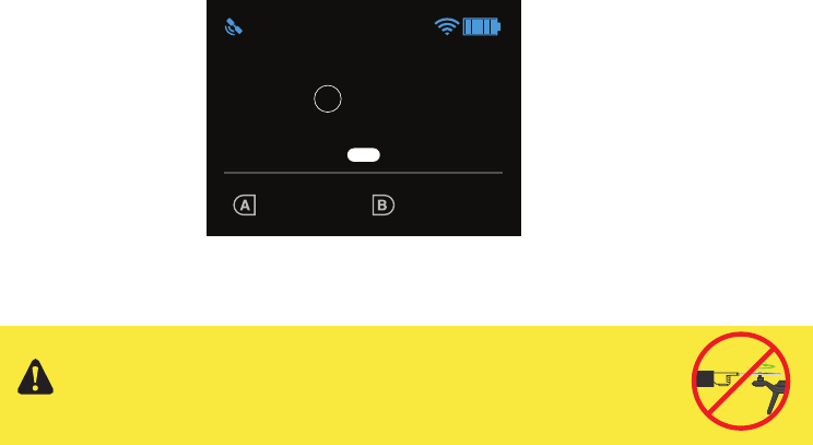
3.10 GPS Management
Solo requires an active GPS signal for advanced automated functions and Smart Shots. After powering on, Solo will
wait to acquire a strong GPS lock. The following requirements define a GPS lock:
• Reported horizontal position accuracy < 16 ft. (5 m)
• Reported speed accuracy < 2 mph (1 m/s)
• Number of satellites ≥ 6
• Difference between GPS and inertial navigation vertical velocity < 2 mph (1 m/s)
After acquiring GPS lock, Solo will enter into standard flight, known as fly mode, and all advanced features and
Smart Shots will be available, including return home. If GPS lock is not acquired before takeoff, return to home will
be unavailable for the duration of the flight and the user will have the option of taking off in non-GPS-assisted fly:
manual mode by pressing A (Figure 3.10.1).
Figure 3.10.1: Controller Waiting-for-GPS Prompt
If GPS is lost during flight, the controller will display the screen shown in Figure 3.10.2 and switch from GPS-
assisted fly mode to fly: manual. If GPS is recovered during flight, the user will be informed that standard fly is now
available.
Figure 3.10.2: Controller GPS Lost Notification
IN-FLIGHT ALERTS
Maximum Altitude
User is told that maximum altitude has been reached
Vehicle is not able to go higher than max altitude
Alert persists until:
TIMEOUT: 5000 milliseconds
Maximum altitude
Solo has reached preset
maximum altitude
Crash Detected
User is prompted to use app to log a support ticket
Alert persists until:
User presses A
Crash detected
Use 3DR Solo app to
log a support ticket
GPS signal lost (Switches to FLY: Manual)
Alert persists until:
TIMEOUT: 3000 milliseconds
GPS lost
Switching to manual control
Shot list and Return to Home
are not available
GPS signal recovered (Switches to FLY: Manual)
Alert persists until:
TIMEOUT: 3000 milliseconds
GPS recovered
Press FLY to set home location
Press to dismiss
FLY
Press to take control
GPS Check
(Advanced mode not enabled) (Advanced mode enabled)
GPS lock confirmation
Fly button prompt is displayed
GPS Check
(Advanced mode not enabled)
System must have GPS lock in order to
reach Fly-button screen.
Searches for GPS lock until it is achieved
GPS lock takes user to Fly-button screen.
Cable Cam
FLIGHT
BATTERY
100%
FLY
Hold to start motors
Orbit
555656
FLY
User flies with Fly: Manual setting
(Advanced mode enabled)
GPS lock confirmation
Fly button prompt is displayed
GPS Check
User is able to skip and fly without GPS
Persists until GPS lock is achieved or users presses A.
Cable Cam Orbit
FLIGHT
BATTERY
100%
555656
Cable Cam Orbit
FLIGHT
BATTERY
100%
FLY
Hold to start motors
555656
FLY
User skips GPS Check
Presses A to use Fly: Manual
Spot lock Rewind
FLIGHT
BATTERY
100%
FLY
Hold to start motors
555656
FLY
Spot lock Rewind
FLIGHT
BATTERY
100%
FLY
Hold to start motors
555656
FLY
Spot lock Rewind
FLIGHT
BATTERY
100%
FLY
Hold to start motors
555656
FLY: Manual
FLY
Waiting for GPS
Fly: Manual Orbit
FLIGHT
BATTERY
100%
555656
FLY: MANUAL
Waiting for GPS
20
3.11 Signal Management
Flying behind solid objects, like buildings and trees, blocks communication signals between Solo and the controller.
Always maintain visual contact with Solo to ensure that the signal is unobstructed. Cell phone towers and nearby
WiFi signals can cause interference with the communication system and decrease its range. Avoid flying in
populated areas to avoid sources of interference.
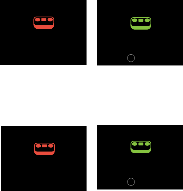
If the communication signal with the controller is lost during flight, Solo will automatically return home if it has GPS
lock. If the signal is recovered, the user will be prompted to re-take control and cancel the return-home command.
Figure 3.11.1: Controller Signal Lost Warnings With GPS
If there is no GPS lock and the controller signal is lost, Solo will initiate an emergency landing and display the screen
shown in Figure 3.11.2.
Figure 3.11.2: Controller Signal Lost Warnings Without GPS
IN-FLIGHT ALERTS: CONTROLLER RELATED
RC Failsafe
Controller signal lost, RTH screen
Alert persists until:
TIMEOUT: 5000 milliseconds
Controller signal lost
Returning to home
RC Signal Recovered
User can press Fly to recover
Alert persists until:
User presses Fly and enters Fly mode
HAPTIC: 40millisecond so user is aware that they can take control
RC Signal Recovered (No GPS)
User can press Fly to enter Fly:Manual
Alert persists until:
User presses Fly and enters Fly: Manual
RC Failsafe (No GPS)
Controller signal lost,
emergency land screen
Alert persists until:
TIMEOUT: 5000 milliseconds
Controller Value out of Range
User is asked to contact customer support
Alert persists until:
TIMEOUT: 5000 milliseconds
go to persistent hint-box message
(persistent until reboot)
Control stick error
Solo will return to home
Contact 3DR Support after landing
Signal recovered
Solo will enter Fly:Manual
FLY
Press to take control
Signal recovered
FLY
Press to take control
Controller signal lost
Controller signal lost, GPS signal lost
Emergency landing started
003
Control stick error
Contact 3DR Support after landing
ALTITUDE
006
005
FLIGHT
BATTERY
100%
RETURN TO HOME
Camera paddle and dial failure
Alert triggered on input error on the paddle
or tilt speed dial potentiometers
TIMEOUT: 5000 milliseconds
003
Spot lock Rewind
ALTITUDE
002
009
FLIGHT
BATTERY
100%
Manual camera controls error
Contact 3DR Support
FLY
21
4 Operating Procedures
This section covers the complete procedures for flying Solo, including preflight checks, manual control, automatic
recall, and Smart Shots.
4.1 Preflight Checklist
Before flying, check the following operating conditions.
Location
-Current location and environmental conditions are suitable for flight. (See page 18 for safe flight guidelines.)
-Solo is placed at a clear launch point, facing away from you. (See page 18 for home position instructions.)
Components
-The propellers are correctly attached. (See page 14 for propeller installation instructions.)
-The propellers can spin smoothly and without obstruction when turned.
-No components on Solo appear loose or damaged.
Power
-The controller is powered on with at least 50% charge. (See page 13 for controller setup instructions.)
-Solo is powered on with the fully charged battery. (See page 11 for battery setup instructions.)
-The camera is attached, powered on and recording. (See page 15 for camera setup instructions.)
-Your phone or tablet is attached to the controller with the Solo app on and streaming video.
(See page 15 for app setup instructions.)
4.2 Takeoff
There are two options for taking off: manual and automatic. We recommend using automatic takeoff to begin the
flight.
Start Motors
When you’re ready to fly, the controller will prompts you to hold the fly button to start Solo’s motors. Hold fly until
the propellers spin. Solo is now active, ready for takeoff, and needs to be treated with appropriate caution to avoid
safety hazards.
Figure 4.2.1: Controller Start Motors Prompt
GPS Check
(Advanced mode not enabled) (Advanced mode enabled)
GPS lock confirmation
Fly button prompt is displayed
GPS Check
(Advanced mode not enabled)
System must have GPS lock in order to
reach Fly-button screen.
Searches for GPS lock until it is achieved
GPS lock takes user to Fly-button screen.
Cable Cam
FLIGHT
BATTERY
100%
FLY
Hold to start motors
Orbit
555656
FLY
User flies with Fly: Manual setting
(Advanced mode enabled)
GPS lock confirmation
Fly button prompt is displayed
GPS Check
User is able to skip and fly without GPS
Persists until GPS lock is achieved or users presses A.
Cable Cam Orbit
FLIGHT
BATTERY
100%
555656
Cable Cam Orbit
FLIGHT
BATTERY
100%
FLY
Hold to start motors
555656
FLY
User skips GPS Check
Presses A to use Fly: Manual
Spot lock Rewind
FLIGHT
BATTERY
100%
FLY
Hold to start motors
555656
FLY
Spot lock Rewind
FLIGHT
BATTERY
100%
FLY
Hold to start motors
555656
FLY
Spot lock Rewind
FLIGHT
BATTERY
100%
FLY
Hold to start motors
555656
FLY: Manual
FLY
Waiting for GPS
Fly: Manual Orbit
FLIGHT
BATTERY
100%
555656
FLY: MANUAL
Waiting for GPS
Spinning propellers can cause serious injury! Always make
sure Solo is clear of any obstructions and all people and animals
are away from Solo before spinning the props.
400 ft
400 ft

22
Automatic Takeoff
Hold fly again to initiate automatic takeoff. Solo will rise to 10 ft and hover until receiving further control inputs.
Figure 4.2.2: Controller Auto-Takeoff Prompt
Manual Takeoff
Once the propellers are spinning, raise the throttle stick above the center position to increase Solo’s altitude and
take off.
4.3 Land
There are three options for landing Solo: manual, automatic, and return to launch. We recommend automatic landing
and return to launch.
Automatic Land
For auto-landing (recommended), press the Fly button in flight, and Solo will land at the current position.
Optionally, you can auto-land Solo at the home position using the controller’s return to home button. (See page 11
for more information about return to home.) After an auto-landing or return-to-home, the propellers will stop spinning
automatically; wait until the propellers stop spinning before approaching Solo.
Return Home
The return-to-home button ends your flight automatically by first returning Solo to the home position (launch point)
then auto-landing. The propellers stop spinning automatically after activating return-to-home.
When commanded to return to home, Solo:
1 Achieves minimum altitude of 50 feet or maintains current altitude if above 50 ft.
2 Moves to launch point and loiters for 5 seconds.
3 Lands at the home point, and the propellers automatically stop after a few seconds.
Figure 4.3.1: Return Home Behavior
home
50 ft. hover 5 seconds
TAKEOFF PART 2
Auto-takeo
User holds “Fly” to initiate auto-takeo.
“Fly” button LED blinks on Artoo when motors
are on. LED becomes solid white when takeo
begins.
Telemetry
Back on telemetry screen after auto-takeo.
Auto-takeo message
During auto-takeo, target altitude message is
displayed.
Message times out after 3000 milliseconds.
005
Spot lock Rewind
ALTITUDE
000
003
FLIGHT
BATTERY
100%
LOITER
AUTO-TAKEOFF
003
Spot lock Rewind
ALTITUDE
004
002
FLIGHT
BATTERY
100%
Spot lock Rewind
FLIGHT
BATTERY
100%
FLY
Hold for auto-takeoff
555656
GOING TO 5 FT ALTITUDE
Auto-takeo
User holds “Fly” to initiate auto-takeo.
“Fly” button LED blinks on Artoo when motors
are on. LED becomes solid white when takeo
begins.
Haptic: press and hold feedback is given.
Spot lock Rewind
FLIGHT
BATTERY
100%
FLY
Hold for auto-takeoff
555656
Auto-takeo
Green bar returns to zero progress position
on transition.
User holds “Fly” to initiate auto-takeo.
“Fly” button LED blinks on Artoo when motors
are on. LED becomes solid white when takeo
begins.
Spot lock Rewind
FLIGHT
BATTERY
100%
FLY
Hold for auto-takeoff
555656
FLY
FLY
FLY
FLY
Banner height
65 px height (from bottom)
or starts at 0,175
136,92
48,92 98,86
When commanded to auto-land, Solo will land at the current position
wherever it is. Always make sure there is a clear path to a safe landing
point directly below Solo before triggering an auto-landing.
400 ft
400 ft

23
Manual Land
For manual landing, move the left stick slightly below center, and slowly decrease Solo’s altitude. When it is a
few inches above the ground, hold the left stick fully back. Continue to hold the left stick fully back and hold the
controller’s Fly button until the props stop spinning.
4.4 In-Flight Data
Use the controller’s main data display to monitor Solo’s status in flight.
Figure 4.4.1: Controller In-Flight Data Display
1 Current altitude in feet
Keep Solo below 400 feet at all times. Solo returns to home if flown higher than 400 feet from home.
2 GPS signal status
Icon illuminates to indicate active GPS lock. GPS flight, pause, return to home, selfie and cable cam
modes require GPS lock. Solo automatically switches to manual flight when no GPS lock is available.
3 Percentage of Solo battery remaining
The controller provides notifications at 20% and 10% to end your flight. At 0%, Solo automatically
lands at the current position.
4 Signal strength between Solo and controller
Solo returns to home if the signal between Solo and the controller is lost during flight.
5 Controller battery level
The controller provides a notification to end your flight when the controller battery is low. When the
controller battery reaches 0%, Solo automatically returns to home.
6 Current distance from the home point in feet
Keep Solo within 2,000 feet from home at all times. Solo return to home if flown farther than 2,000 feet
from home.
7 Current speed in miles per hour
8 Current mode
9 Currently assigned functions of controller A and B buttons
Never approach Solo while the propellers are spinning. After an
auto-landing or return-to-home, always wait until the propellers stop
before approaching or touching Solo. For a manual landing, hold the
Fly button until the propellers stop before handling Solo.
TAKEOFF PART 2
Auto-takeo
User holds “Fly” to initiate auto-takeo.
“Fly” button LED blinks on Artoo when motors
are on. LED becomes solid white when takeo
begins.
Telemetry
Back on telemetry screen after auto-takeo.
Auto-takeo message
During auto-takeo, target altitude message is
displayed.
Message times out after 3000 milliseconds.
005
Spot lock Rewind
ALTITUDE
000
003
FLIGHT
BATTERY
100%
LOITER
AUTO-TAKEOFF
003
Spot lock Rewind
ALTITUDE
004
002
FLIGHT
BATTERY
100%
Spot lock Rewind
FLIGHT
BATTERY
100%
FLY
Hold for auto-takeoff
555656
GOING TO 5 FT ALTITUDE
Auto-takeo
User holds “Fly” to initiate auto-takeo.
“Fly” button LED blinks on Artoo when motors
are on. LED becomes solid white when takeo
begins.
Haptic: press and hold feedback is given.
Spot lock Rewind
FLIGHT
BATTERY
100%
FLY
Hold for auto-takeoff
555656
Auto-takeo
Green bar returns to zero progress position
on transition.
User holds “Fly” to initiate auto-takeo.
“Fly” button LED blinks on Artoo when motors
are on. LED becomes solid white when takeo
begins.
Spot lock Rewind
FLIGHT
BATTERY
100%
FLY
Hold for auto-takeoff
555656
FLY
FLY
FLY
FLY
Banner height
65 px height (from bottom)
or starts at 0,175
136,92
48,92 98,86
2
3 4 5
6
7
8
9
1

24
4.5 Joystick Control
The controller’s two joysticks allow you to navigate Solo in flight. The left stick controls Solo’s altitude and rotation.
Figure 4.5.1: Controller Left Joystick
Move the left stick vertically to control Solo’s altitude and acceleration.
Figure 4.5.2: Throttle Joystick Behaviors
UP
DOWN
ROTATE
LEFT
ROTATE
RIGHT
Left Stick
Move the left stick back from
center to decrease altitude.
Set the left stick to center to
maintain the current altitude.
Left Stick
Set the left stick fully back to
land once Solo is a few inches
above the ground.
Left Stick
To take off and to gain altitude,
move the left stick slightly past
the center position.
Left Stick

25
Move the left stick horizontally to rotate Solo and control orientation.
Figure 4.5.3: Yaw Joystick Behavior
Use the right stick to fly Solo forward, back, left and right in space. These movements are relative to Solo’s current
orientation, so always maintain awareness of Solo’s forward-facing direction before using right stick controls.
Figure 4.5.4: Controller Right Joystick Controls
Activate
Hold until propellers
start spinning.
Take-off + Lift
Raise just slightly
for take off
Hover + Land
Lower just slightly
to hover
Left Yaw
Left
Back
Forward
Right
Right Yaw
Deactivate
Hold until propellers
stop spinning
Activate
Hold until propellers
start spinning.
Take-off + Lift
Raise just slightly
for take off
Hover + Land
Lower just slightly
to hover
Left Yaw
Left
Back
Forward
Right
Right Yaw
Deactivate
Hold until propellers
stop spinning
Move the stick to the left to
rotate counterclockwise.
Move the stick to the right to
rotate clockwise.
Left Stick
Release the stick to stop
rotating the maintain the
current orientation
LEFT RIGHT
FORWARD
BACK

26
Move the right stick vertically to control pitch.
Figure 4.5.5: Pitch Joystick Controls
Move the right stick horizontally to control roll.
Figure 4.5.6: Roll Joystick Controls
Activate
Hold until propellers
start spinning.
Take-off + Lift
Raise just slightly
for take off
Hover + Land
Lower just slightly
to hover
Left Yaw
Left
Back
Forward
Right
Right Yaw
Deactivate
Hold until propellers
stop spinning
Activate
Hold until propellers
start spinning.
Take-off + Lift
Raise just slightly
for take off
Hover + Land
Lower just slightly
to hover
Left Yaw
Left
Back
Forward
Right
Right Yaw
Deactivate
Hold until propellers
stop spinning
Move the right stick
forward to fly forward.
Move the right stick
back to fly backward.
Activate
Hold until propellers
start spinning.
Take-off + Lift
Raise just slightly
for take off
Hover + Land
Lower just slightly
to hover
Left Yaw
Left
Back
Forward
Right
Right Yaw
Deactivate
Hold until propellers
stop spinning
Activate
Hold until propellers
start spinning.
Take-off + Lift
Raise just slightly
for take off
Hover + Land
Lower just slightly
to hover
Left Yaw
Left
Back
Forward
Right
Right Yaw
Deactivate
Hold until propellers
stop spinning
Move the right stick
left to fly left.
Move the right stick right
to fly right.
If you’re new to drones, take some time to learn the basics before your
first flight. Visit 3dr.com/solo/info or check out Flight School in the Solo
app to learn about flight controls and best practices.
27
4.6 Smart Shots
Solo’s Smart Shots automate video capturing to make it easy to replicate traditional filming techniques. Smart Shots
can be useful for designing artistic video or for automating the flight procedure to restrict Solo to within a designated
area.
Selfie
Solo performs an automated maneuver to capture a subject in a cinematic establishing shot.
To take a selfie:
1. Navigate Solo manually so the subject appears in the video frame with Solo
approximately 10 feet from the subject.
2. Ensure that there is 100 feet of unobstructed space behind and above Solo.
3. Press A to start the selfie.
4. Solo flies backward 100 ft and upward 100 ft in a smooth arc.
5. Press pause to stop the automatic maneuver and use the right stick to move
manually along the selfie path.
Use the Solo app to configure the distance and speed of the selfie shot or to activate selfie mode
before takeoff.
Cable Cam
Create a smooth shot by flying Solo along an invisible cable between two preset points.
To fly a cable cam:
1. Press B to enter cable cam mode.
2. Navigate Solo manually to the first point so the video displays the desired subject,
and press A to save the first point.
3. Navigate manually to the second point, and press A again to save the second point.
Add a difference of altitude or orientation between the two points for an impressive
cinematic effect.
4. Use the right stick to fly along the cable in either direction.
Use the Solo app to configure and interact with automatic cable cam shots.
28
5 Maintenance
Solo’s components are designed to absorb impact from hard landings and protect the core electronics. If damage is
sustained to Solo’s legs or motors, replace them with official 3DR parts from store.3dr.com or an authorized retailer.
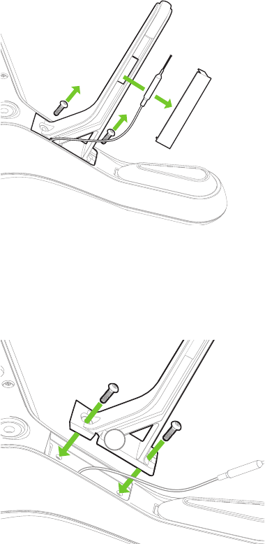
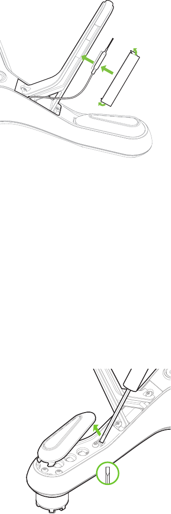
5.1 Legs
To replace one of Solo’s legs, purchase a Leg Replacement Set form store.3dr.com or an authorized retailer.
1 Remove the plastic sheet from the leg.
2 Detach the antenna.
3 Use a #2 Phillips screwdriver to remove the two screws and detach the old leg.
(For legs without an antenna module, remove the two screws and replace the leg only.)
Figure 5.1.1: Leg Replacement Process 1
1 Thread the antenna cable through the notch in the new leg. Be careful not to crush the cable.
2 Secure the leg using the two screws.
Figure 5.1.2: Leg Replacement Process 2
1
2
3
2
1
29
1 Affix the antenna to the inside of the leg.
2 Fold the ends of the new plastic sheet at right angles.
3 Remove the adhesive backing and stick the plastic sheet to the leg so it secures the antenna in place.
Figure 5.1.3: Leg Replacement Process 3
Replacing the Right-Rear Leg
Solo’s right-rear leg (arm #04) contains the compass module. To replace the right-rear leg, purchase a Solo
Replacement Leg with Compass from store.3dr.com or an authorized retailer.
5.2 Motors
Replacement motors are available as clockwise and counterclockwise motor pods. Use a counterclockwise motor
pod to replace motors on arms #01 and #02, and use a clockwise motor pod to replace motors on arms #03 and
#04.
First, use a small, flat prying tool to remove the LED cover form the underside of the arm.
Figure 5.2.1: Motor Pod Replacement Process 1
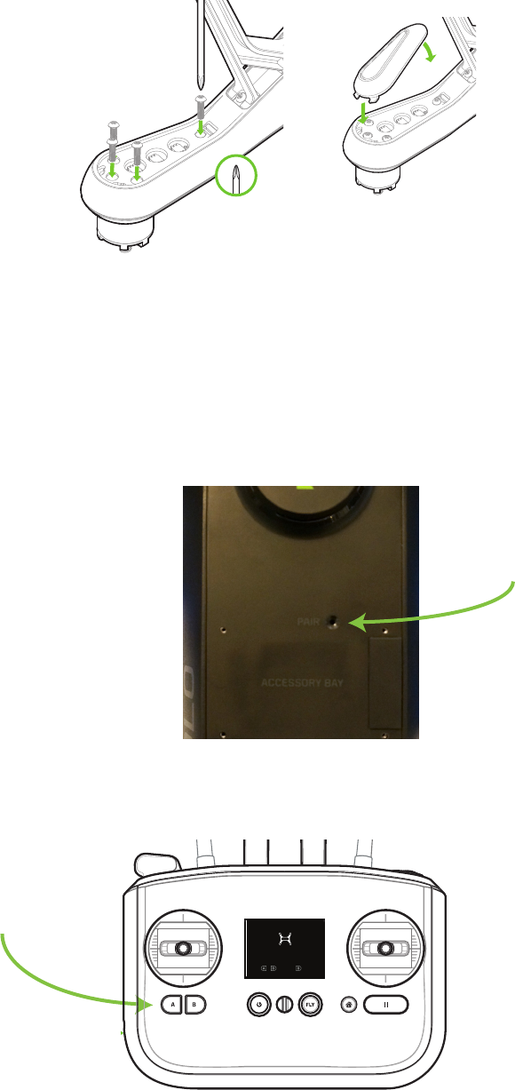
Use a #2 Phillips screwdriver to remove the four screws securing the pod to the arm. (Figure 5.2.2 not to scale.)
4
3
2

30
Figure 5.2.2: Motor Pod Replacement Process 2
Disconnect the wide beige connector, the red wire and the black wire to remove the old motor pod. To remove the
wide beige connector, carefully lift the edges of the connector away from the pod until they pop out then remove the
connector. Don’t pull on the wires! The connector can break easily if force is used to remove it.
Figure 5.2.3: Motor Pod Replacement Process 3
Connect the 3 cables from the arm to the new motor pod. Tuck cables inside the arm, and set the pod into place.
Figure 5.2.4: Motor Pod Replacement Process 4
31
Turn over Solo and replace the 4 screws to secure the new motor pod into place. Snap the LED cover back into
place by positioning the front (1) and snapping the back tab into place (2).
Figure 5.2.5: Motor Pod Replacement Process 5
5.3 Pairing
To pair a new controller with Solo, first power both the controller and Solo. Power off any other Solos or controllers
in the vicinity. Once powered, press the pair button on the underside of Solo to activate pairing mode. To cancel
pairing, press B.
Figure 5.3.1: Solo Pair Button
The controller will automatically detect Solo and prompt you to pair. Hold the A and B buttons on the controller to
start pairing.
Figure 5.3.2: Controller Pairing Process
1
2
SOLO-ARTOO PAIRING V5
User presses “Pair” on Solo
Reaches this screen after pressing “Pair”
User available actions:
A+B: Pair to Solo
B: Cancel pairing
Timeout
If no action is taken, pairing invitation times out after
30,000 milliseconds. (Feedback is shown)
Display when pairing invitation times out after 30 sec
Message timeout after 4000 milliseconds
Display when pairing has failed.
Message timeout after 4000 milliseconds
detected new Solo
to cancel
+
Hold to pair
detected new Solo
to cancel
+
Hold to pair
pairing canceled
Display on B button press. Timeout after 4000 milliseconds
User cancels. Timeout after 4000 milliseconds
pairing timed out
Press pair button on Solo to try again
pairing failed
Press pair button on Solo to try again
Display on pairing success. Timeout after 4000 milliseconds
Solo paired
pairing in progress
pairing canceled
User cancels with B
Haptic: 40 millisecond pulse immediately after A+B press
Message is displayed until following states are triggered.
32
6 Appendix
6.1 Specifications and Operating Parameters
Solo is a quad-rotor aerial vehicle powered by the 3DR Pixhawk 2 autopilot system and APM:Copter 3.3
flight control software. Solo communicates with the controller and Solo app over the 3DR Link secure wireless
connection.
Autopilot: 3DR Pixhawk 2
Flight code: APM:Copter 3.3
Control: 3DR Solo Controller
Wireless communication: 3DR Link 1.0
Frequency: 2.4 GHz
Height: 10.2 in.
Motor-to-motor dimension: 18.1 in.
Propulsion: 880 KV motors, two clockwise rotating motors and
two counterclockwise rotating motors
Propeller: 10 in. x 4.5 in.
Weight with battery: 3.3 lbs.
Controller battery life: 6 hours
Controller battery: Li-ion 2600 mAh 7.2 Vdc (5200 mAh for extended battery)
Power: Electric (rechargeable lithium polymer battery)
Battery: Lithium polymer, 5200 mAh, 14.8 Vdc
Battery weight: 1 lb.
Estimated flight time: 25 minutes*
Maximum altitude: 400 ft.
Range: 2,500 ft. from launch point**
Payload capacity: 1.1 lbs.
Cruise speed: 5.7 mph (2.5 m/s)
Maximum speed: 55 mph (25.5 m/s)
Maximum climb rate: 11 mph (5.0 m/s)
Maximum descent rate: 5.5 mph (2.5 m/s)
Headwind limitation: 17 mph (7.7 m/s)
Crosswind limitation: 17 mph (7.7 m/s)
Camera: Streaming video compatible with GoPro® HERO 3, 3+ or 4
Full compatibility with GoPro® HERO 3+ or 4
Solo app compatibility: iOS 8.0 or later / Android 4.1.2 or later
Operating temperature: 32° F - 113° F (0° C - 45° C)
Operating relative humidity: 0-85% RH
*Flight time varies with payload, wind conditions, elevation, temperature, humidity, flying style,
and pilot skill. Listed flight time applies to elevations less than 2,000 ft above sea level.
**Range varies with location, antenna orientation, background noise and multi-path.
33
6.2 Warranty
3D Robotics warrants to the original retail purchaser of Solo (the “Product”) that at the time of purchase that this
product is free from material defect in materials and workmanship. Should this Product fail during normal consumer
usage and conditions due to defective material or workmanship within one year from the date of purchase, or such
longer period as is required by applicable law (“Warranty Period”), such defect(s) will be
repaired or replaced at 3D Robotics’ option, without charge for parts or labor directly related to the defect(s). The
complete terms of the limited warranty applicable to Solo can be found at 3dr.com/terms.
This Warranty extends only to consumers who purchase the product from a 3D Robotics authorized reseller and is
not transferable or assignable. This Warranty does not apply to: (1) Product subjected to abnormal use
or conditions, accident (including without limitation, collision, crash or fire), alteration, or improper repair; (2)
damage from exposure to moisture or extreme environmental conditions; (3) damage from use with any
accessory, software or other product not expressly authorized by 3D Robotics; (4) damage from external causes
such as dirt, sand, battery leakage, blown fuse, or improper usage of any electrical source; (5) commercial use; or (6)
use in violation of law or ordinances in effect in the jurisdiction in which the Product is used.
3D Robotics assumes no liability for any accident, injury, death, loss, or other claim related to or resulting from
the use of this product. 3D Robotics makes no other warranties for Solo, and makes no warranties whatsoever
for service, software, maintenance or support for non-3D Robotics branded products. Such products, service,
software, maintenance or support is provided by 3D Robotics “As Is” and any third-party warranties, products,
software, services, maintenance or support are provided by the original manufacturer or supplier, not by 3D
Robotics.
Software is subject to the separate software license agreement accompanying or made available to you in
connection with the software. A portion of the software contains or consists of open-source software, which you
may use under the terms and conditions of the specific license under which the open-source software is distributed.
You agree that you will be bound by any and all such license agreements, and that your usage of this product
indicates your acceptance of those agreements. Title to software remains with the applicable licensor(s). In no event
will 3D Robotics be liable to you for damages, including any general, special, incidental or consequential damages
arising out of the use or inability to use the software.
THE EXTENT OF 3D ROBOTICS’ LIABILITY UNDER THIS WARRANTY IS LIMITED TO THE REPAIR OR
REPLACEMENT PROVIDED ABOVE AND, IN NO EVENT, SHALL ITS LIABILITY EXCEED THE PURCHASE PRICE
PAID BY PURCHASER FOR THE PRODUCT.
6.3 Regulatory Compliance
U.S. - FCC (Federal Communication Commission)
3DR Solo FCC: 2ADYD-S111A
3DR Solo Controller FCC: 2ADYD-AT11A
This device complies with Part 15 of the FCC rules. Operation is subject to the following two conditions: (1) This
device may not cause harmful interference, and (2) this device must accept any interference received, including
interference that may cause undesired operation.
Changes or modifications not expressly approved by 3D Robotics could void the user’s authority to operate the
equipment.
Radiation Exposure Statement:
The Solo system has been tested to ensure compliance with FCC-mandated limits for general population radio
frequency (RF) exposure for an uncontrolled environment. These limits ensure that no harmful effects will result from
operating Solo according to the standard operating procedures described in this manual.
34
The body’s Specific Absorption Rate (SAR) for the Solo controller is 1.33 watts per kilogram (W/kg) in compliance
with the FCC limit of 1.6 W/kg. To reduce exposure to RF energy, hold Solo at least 20 cm away from your body at
all times during operation. Do not operate the Solo controller co-located or in conjunction with any other antenna or
transmitter.
This device complies with Part 15 of the FCC Rules. Operation is subject to the condition that this device does not
cause harmful interference.
Canada - Industry Canada
3DR Solo IC: 12768A-S114A
Model number: S110A
3DR Solo Controller IC: 12768A-AT14A
Model number: AT10A
This device complies with Industry Canada licence-exempt RSS standard(s). Operation is subject to the following
two conditions: (1) this device may not cause interference, and (2) this device must accept any interference,
including interference that may cause undesired operation of the device.
Le présent appareil est conforme aux CNR d’Industrie Canada applicables aux appareils radio exempts de licence.
L’exploitation est autorisée aux deux conditions suivantes : (1) l’appareil ne doit pas produire de brouillage, et (2)
l’utilisateur de l’appareil doit accepter tout brouillage radioélectrique subi, même si le brouillage est susceptible d’en
compromettre le fonctionnement.
IC Radiation Exposure Statement:
The Solo system has been tested to ensure compliance with IC-mandated limits for general population radio
frequency (RF) exposure for an uncontrolled environment. These limits ensure that no harmful effects will result
from operating Solo according to the standard operating procedures described in this manual. To reduce exposure
to RF energy, hold Solo at least 20 cm away from your body at all times during operation. Do not operate the Solo
controller co-located or in conjunction with any other antenna or transmitter. Changes or modifications not expressly
approved by 3D Robotics could void the user’s authority to operate the equipment.
6.4 Sensor Data Sheets
Pixhawk Flight Management Unit:
- InvenSense MPU6000 integrated accelerometer/gyroscope
http://www.invensense.com/mems/gyro/mpu6050.html
- Honeywell HMC 5983 temperature compensated magnetometer
http://www51.honeywell.com/aero/common/documents/myaerospacecatalog-documents/Defense_Brochures-
documents/HMC5983_3_Axis_Compass_IC.pdf
- Measurement Specialties MS5611 Barometer
http://www.meas-spec.com/product/pressure/MS5611-01BA03.aspx
Pixhawk Stabilized Internal Measurement Unit:
- InvenSense MPU6000 integrated accelerometer/gyroscope
http://www.invensense.com/mems/gyro/mpu6050.html
- Measurement Specialties MS5611 Barometer
http://www.meas-spec.com/product/pressure/MS5611-01BA03.aspx
35
- STMicroelectronics LSM303D integrated accelerometer/magnetometer
http://www.st.com/web/catalog/sense_power/FM89/SC1449/PF253884
- STMicroelectronics L3GD20 gyroscope
http://www.st.com/web/catalog/sense_power/FM89/SC1288/PF252443?sc=internet/analog/product/252443.jsp
3DR GPS Module:
- u-blox NEO-7N
http://www.u-blox.com/en/gps-modules/pvt-modules/neo-7.html
-Taoglas GPS Patch Antenna, 1575MHz
http://www.taoglas.com/images/product_images/original_images/GP.1575.25.4.A.02%20GPS%20Patch%20
Antenna%201575MHz%20280110.pdf
3DR Compass Module:
- Honeywell HMC 5983 temperature compensated magnetometer
http://www51.honeywell.com/aero/common/documents/myaerospacecatalog-documents/Defense_Brochures-
documents/HMC5983_3_Axis_Compass_IC.pdf

This page left intentionally blank.