3e Technologies 523E-900 WiMesh End Point Kit 900 MHz Option User Manual 3e 523 525N Family User Guide
3e Technologies International, Inc. WiMesh End Point Kit 900 MHz Option 3e 523 525N Family User Guide
User Manual Revised
Copyright 2015 Ultra Electronics, 3eTI
October 2015
i
29000169-005 Revision C1
AirGuard WiMesh 3e-523 Series
Models: 3e–523A, 3e-523S, 3e-523E-900,
and 3e-523M (OEM Module)
User’s Guide
Ultra Electronics, 3e TI
9713 Key West Ave, Suite 500
Rockville, MD 20850
(800) 449-3384
www.ultra-3eti.com
October 2015
29000169-005 Revision C1

AirGuard WiMesh 3e-523 Series User’s Guide
Copyright 2015 Ultra Electronics, 3eTI
October 2015
1
29000169-005 Revision C1
This page intentionally left blank.

AirGuard WiMesh 3e-523 Series User’s Guide
Copyright 2015 Ultra Electronics, 3eTI
October 2015
2
29000169-005 Revision C1
Copyright © 2015 Ultra Electronics, 3eTI, All rights reserved. No part of this document may be reproduced
in any form or by any means or to make any derivative work (such as translation, transformation, or
adaptation) without written permission from 3eTI.
3eTI reserves the right to revise this document and to make changes in content from time to time without
obligation on the part of 3eTI to provide notification of such revision or change.
3eTI provides this document without warranty, term or condition of any kind, either implied or expressed,
including, but not limited to, the implied warranties, terms, or conditions of merchantability, satisfactory
quality, and fitness for a particular purpose. 3eTI may make improvements or changes in the product(s)
and/or the program(s) described in this document at any time. Certain features listed may have restricted
availability and/or are subject to change without notice - please confirm material features when placing
orders.
If there is any software or removable media described in this document, it is furnished under a license
agreement included with the product as a separate document, in the printed document, or on the removable
media in a readable file such as license.txt or the like. If you are unable to locate a copy of the license,
contact 3eTI and a copy will be provided to you.
GOVERNMENT RIGHTS LEGEND
The U.S. Government’s rights in this document, the products described, and all technical data and
computer software are limited by DFARS 252.227 7014 pertaining to restricted rights software, and DFAR
252.227-7015 pertaining to limited rights technical data developed at private expense; or currently limited
under DFARS 252.227-7018 small business innovative research programs, whichever is applicable. 3eTI,
the 3eTI logo and AirGuard are registered trademarks.
Sensus is a registered trademark of Sensus.
ISA100.11A is a registered trademark of International Society of Automation.
Windows is a registered trademark of Microsoft Corporation. Any other company and product name
mentioned herein is a trademark of the respective company with which they are associated.
EXPORT RESTRICTIONS
This product contains components, software, and/or firmware exported from the United States in
accordance with U.S. export administration regulations. Diversion contrary to U.S. law is prohibited.

AirGuard WiMesh 3e-523 Series User’s Guide
Copyright 2015 Ultra Electronics, 3eTI
October 2015
3
29000169-005 Revision C1
Table of Contents
1. Introduction…………. ....................................................................................................................... 6
1.1 Basic Features ............................................................................................................................ 6
1.2 Wireless Basics ........................................................................................................................... 7
1.2.1 Bridging / Mesh Operation .................................................................................................. 8
1.2.2 Access Point Operation ...................................................................................................... 8
1.2.3 Client Operation ................................................................................................................. 8
1.2.4 Data Encryption and Security ............................................................................................. 8
1.3 Device Management and Administration ...................................................................................... 9
1.4 Product Family Navigation Options .............................................................................................. 9
2. Device Configuration ..................................................................................................................... 10
2.1 Preliminary Configuration Steps ................................................................................................. 10
2.2 System Configuration ................................................................................................................ 13
2.2.1 General ……………………………………………………………………………………………...13
2.2.2 Operating Mode ............................................................................................................... 14
2.2.3 System Deployment ......................................................................................................... 16
2.2.4 WAN ........................................................................................................................... 16
2.2.5 Serial Port ........................................................................................................................ 17
2.2.6 WLAN QoS/WMM ............................................................................................................ 19
2.3 Wireless AP and Bridge Mode ................................................................................................... 23
2.3.1 Radio Configuration for 3e-523A, 3e-523S and 3e-523M .................................................. 23
2.3.2 Radio Configuration for 3e-523E-900 ............................................................................... 24
2.3.3 Bridge Mode..................................................................................................................... 27
2.3.4 Bridge Encryption ............................................................................................................. 31
2.3.5 MAC Address Filtering ..................................................................................................... 32
2.3.6 AP Encryption .................................................................................................................. 33
2.3.7 Wireless VLAN ................................................................................................................. 35
2.3.8 AP MAC Filtering .............................................................................................................. 41
2.3.9 Rogue AP Detection ......................................................................................................... 42
2.3.10 AP Advanced ................................................................................................................... 43
2.4 Service Settings......................................................................................................................... 44

AirGuard WiMesh 3e-523 Series User’s Guide
Copyright 2015 Ultra Electronics, 3eTI
October 2015
4
29000169-005 Revision C1
2.4.1 SNMP Agent .................................................................................................................... 44
2.4.2 Serial Communication ...................................................................................................... 46
2.4.3 Remote Administration ..................................................................................................... 48
2.5 Admin User Management .......................................................................................................... 49
2.5.1 List All Users .................................................................................................................... 50
2.5.2 Add New User .................................................................................................................. 51
2.5.3 User Login Policy ............................................................................................................. 51
2.6 Monitoring/Reports .................................................................................................................... 53
2.6.1 System Status .................................................................................................................. 54
2.6.2 Bridging Status ................................................................................................................. 54
2.6.3 Bridge Site Map................................................................................................................ 55
2.6.4 Wireless Clients ............................................................................................................... 56
2.6.5 Adjacent AP List ............................................................................................................... 57
2.7 Logs .......................................................................................................................... 57
2.7.1 System Log ...................................................................................................................... 58
2.7.2 Web Access Log .............................................................................................................. 58
2.8 Auditing ........................................................................................................................... 59
2.8.1 Audit Log.......................................................................................................................... 59
2.8.2 Report Query ................................................................................................................... 60
2.8.3 Configuration.................................................................................................................... 61
2.9 System Administration ............................................................................................................... 63
2.9.1 E-mail Notification Configuration ....................................................................................... 63
2.9.2 Radio Tx Off Control......................................................................................................... 65
2.9.3 System Upgrade .............................................................................................................. 65
2.9.4 Factory Default ................................................................................................................. 67
2.9.5 Remote Logging ............................................................................................................... 68
2.9.6 Reboot ........................................................................................................................... 69
2.9.7 On Demand Self-test ........................................................................................................ 69
2.9.8 Periodic Self-test .............................................................................................................. 70
2.9.9 Utilities ........................................................................................................................... 71
2.9.10 Help .......................................................................................................................... 72
2.10 Operational Configurations ........................................................................................................ 73
3. WiMesh End Points 3e-523A and 3e-523E-900 Hardware Installation ......................................... 82

AirGuard WiMesh 3e-523 Series User’s Guide
Copyright 2015 Ultra Electronics, 3eTI
October 2015
5
29000169-005 Revision C1
3.1 3e-523A Hardware Installation ................................................................................................... 82
3.1.1 Connectors and Cabling ................................................................................................... 83
3.1.2 Indoor Accessory Kit Installation ....................................................................................... 84
3.1.3 Outdoor Accessory Kit Installation .................................................................................... 85
3.1.4 The Indicator Lights .......................................................................................................... 88
3.1.5 Reset Button .................................................................................................................... 89
3.2 3e-523E-900 Hardware Installation ............................................................................................ 90
3.2.1 Specifications ................................................................................................................... 90
3.2.2 Mounting Pattern .............................................................................................................. 91
3.2.3 Installation Requirements ................................................................................................. 92
3.2.4 RF Connections ............................................................................................................... 93
3.2.5 RF Safety Information ...................................................................................................... 93
4. WiMesh PAC-Link (3e-523S) Hardware Overview......................................................................... 94
5. WiMesh End Point OEM Module (3e-523M) ................................................................................... 95
5.1.1 Mechanical Drawings ............................................................................................................ 103
6. Technical Support .................................................................................................................. 104
Appendix A: Glossary ................................................................................................................... 105
Appendix B: Two-Factor Authentication Overview and Configuration .......................................... 106
Appendix C: Common Criteria Supplement .................................................................................... 126

AirGuard WiMesh 3e-523 Series User’s Guide
Copyright 2015 Ultra Electronics, 3eTI
October 2015
6
29000169-005 Revision C1
1. Introduction
This manual covers the installation and operation of the Ultra Electronics, 3eTI AirGuard WiMesh Series
model numbers: 3e–523 family of products. These rugged secure data points have been designed and
tested for use in harsh demanding environments were durability is a key requirement. The 3e-523 product
family consists of the 3e-523A, 3e-523S, 3e-523M and the 3e-523E-900 (hereinafter referred to as the
3e-523, unless otherwise specified).
The 3e-523 includes FIPS-140-2 certified AES/3DES cryptographic modules for wireless encryption and
HTTPS/TLS, for secure web communication.
The cryptographic modules provide the following encryption capabilities.
AES (128/192/256 bit)
AES-CCM (128 bit)
1.1 Basic Features
The AirGuard WiMesh 3e-523 family of products is made up of four different products each designed to
meet specific user needs and requirements. This section provides a general overview of interfaces and
specific capabilities of each product. A more detailed description of the different products can be found in
the product specific chapters found later in this manual.
The WiMesh End Point 3e-523A provides the following interfaces:
One RJ-45 10 / 100 Mbps WAN Ethernet port for remote management and for interfacing to a
wired network.
Two 802.11a/b/g antenna ports.
One DB-15 RS-232/422/485 & power connector.
Device Reset button, provides ability to reset device to either user programmed configuration or
factory default.
Device grounding connector.
The 3e-523A provides the following LED indicator lights:
FIPS LED
WLAN LED
The WiMesh PAC-Link 3e-523S portable adaptive com-link provides the following interfaces:
One RJ-45 10 / 100 Mbps WAN Ethernet port for remote management and for interfacing to a
wired network.
One DB-9 RS-232 serial port for configuration or interfacing to a sensor.
One 802.11a/b/g antenna port.
One external power switch.
The 3e-523S provides the following LED indicator lights:
FIPS LED

AirGuard WiMesh 3e-523 Series User’s Guide
Copyright 2015 Ultra Electronics, 3eTI
October 2015
7
29000169-005 Revision C1
WLAN LED
The WiMesh 3e-523E-900 unit provides the following interfaces:
One RJ-45 10 / 100 Mbps WAN Ethernet cable entry port for remote management and for
interfacing to a wired network.
One 900 MHz N-type female jack antenna connector.
One power entry port.
Device grounding connector.
The WiMesh End Point OEM Module 3e-523M provides the following interface:
One RJ-45 10 / 100 Mbps WAN Ethernet port for remote management and for interfacing to a
wired network.
Two 802.11a/b/g antenna ports.
One 16 pin RS-232/422/485 & Power connector.
One 14 pin connector which brings out LED and Advanced Feature Signals.
1.2 Wireless Basics
Wireless networking uses electromagnetic radio frequency waves to transmit and receive data.
Communication occurs by establishing radio links between the wireless access point and devices
configured to be part of the WLAN.
The 3e-523 incorporates 802.11 Wi-Fi standards, and FIPS 140-2 compliant security for wireless
communication.
802.11a - The IEEE 802.11a standard is an extension to 802.11 that applies to wireless LANs and
provides up to 54 Mbps in the 5 GHz band. Depending on radio design and RF channel issues 802.11a
devices can operation at rates between the 54 Mbps maximum and 6 Mbps. 802.11a uses an Orthogonal
Frequency Division Multiplexing (OFDM) encoding scheme rather than Frequency-Hopping Spread
Spectrum (FHSS) or Direct-Sequence Spread Spectrum (DSSS).
802.11b - The IEEE 802.11b compliant devices provide 11 Mbps transmission (with a fallback to 5.5, 2 and
1 Mbps depending on signal strength) in the 2.4 GHz band. 802.11b devices operate using
Direct-Sequence Spread Spectrum (DSSS) modulation techniques. Note that for the 3e-523E-900 this is
the only mode used, and controls to change this are not available in the configuration software.
802.11g - The IEEE 802.11g standard is an extension to 802.11 that applies to wireless LANs and
provides up to 54 Mbps in the 2.4 GHz band. Depending on radio design and RF channel issues 802.11g
devices can operation at rates between the 54 Mbps maximum and 6 Mbps. Like the 802.11a standard

AirGuard WiMesh 3e-523 Series User’s Guide
Copyright 2015 Ultra Electronics, 3eTI
October 2015
8
29000169-005 Revision C1
802.11g uses an Orthogonal Frequency Division Multiplexing (OFDM) encoding scheme for data
transmission.
Because 802.11g is backwards-compatible with 802.11b, it is a popular component in LAN construction.
802.11g broadens 802.11b’s data rates to 54 Mbps within the 2.4 GHz band providing higher data
transmission rates.
802.11b/g Mixed - 802.11b/g combines 802.11b and 802.11g data rates to offer a broader range of
operation.
1.2.1 Bridging / Mesh Operation
The 3e-523 functions as a bridge. There are a number of bridging configurations supported, including the
following popular configurations:
Point-to-point bridging of 2 Ethernet Links.
Point-to-multipoint bridging (mesh) of several Ethernet links.
Repeater mode (wireless client to wireless bridge).
1.2.2 Access Point Operation
The 3e-523 functions as an access point. In this mode of operation the 3e-523 provides wireless
networking to multiple client devices while providing connectivity into a local area network (LAN).
1.2.3 Client Operation
The 3e-523 can functions as a wireless client. In this mode of operation the 3e-523 acts as a wireless
endpoint providing a communication link into a wireless Local Area Network (LAN) network.
1.2.4 Data Encryption and Security
The 3e-523 includes advanced wireless security features. Bridging encryption can be established between
the 3e-523 using AES-ECB or AES-CCM encryption (approved by the National Institute of Standards and
Technology (NIST) for U.S. Government and DoD agencies). There is also the option of no security, but
some level of security is recommended.
AES - The Advanced Encryption Standard (AES) was selected by National Institute of Standards and
Technology (NIST) in October 2000 as an upgrade from the previous DES standard. AES uses a 128-bit
block cipher algorithm and encryption technique for protecting computerized information. It has the ability
to use even larger 192-bit and 256-bit keys, if desired.
802.11i and WPA2 employ AES CCM, which is a combination of AES Counter (CTR) mode per packet
data encryption, combined with AES Cipher Block Chaining
Message Authentication Code (CBC-MAC) per packet data integrity / authentication of the entire packet
including the MAC header. AES CCMP has been deemed to surpass the RC4 stream cipher, upon which
the older WEP and WPA security protocols are based. 3eTI was the first company to take its AES
algorithm through the NIST CCM algorithm certification process, thereby ensuring that 3eTI’s AES CCMP
is standards-based, non-proprietary, and ready for wide WPA2 interoperability usage.
AirGuard WiMesh 3e-523 Series User’s Guide
Copyright 2015 Ultra Electronics, 3eTI
October 2015
9
29000169-005 Revision C1
Operation Authentication - Authentication mechanisms are used to authenticate an operator accessing
the device and to verify that the operator is authorized to assume the requested role and perform services
within that role.
Access to the management screens for the 3e-523 requires knowledge of the assigned operator ID and
Password. The Factory defaults are:
ID: CryptoOfficer
Password: CryptoFIPS
The Crypto Officer initially installs and configures the 3e-523 after which the password should be changed
from the default password. The ID and Password are case sensitive.
1.3 Device Management and Administration
After initial setup, maintenance of the system and programming of security functions should be performed
by personnel trained in the procedure using the embedded web-based management screens.
The next chapter covers the basic procedure for configuration of 3e-523 devices. Table 1 provides a listing
of the page organization of the 3e-523 data points.
1.4 Product Family Navigation Options
The next chapter covers the basic procedure for setting up the hardware. Table 1 provides an overview of
the web GUI screens and menu structure for used to manage and administer 3e-523 devices
Table 1 - 3e–523 Data Point Navigation Options
System Configuration
Monitoring/Reports
General
System Status
Operating Mode
Bridging Status
System Deployment
Bridging Site Map
WAN
Wireless Clients
Serial Port
Adjacent AP List
WLAN QoS/WMM
Logs
Wireless AP & Bridge
System Log
Radio
Web Access Log
Bridge Mode
Auditing
Bridge Encryption
Audit Log
Bridge MAC Filtering
Report Query
AP Encryption
Configuration
Wireless VLAN
System Administration
AP MAC Filtering
Email Notification Conf
Rogue AP Detection
Radio Tx Off Control
AP Advanced
System Upgrade
Services Settings
Factory Default
SNMP Agent
Remote Logging
Serial Communication
Reboot
Remote Administration
On Demand Self-Test
Admin User Management
Periodic Self Test
List All Users
Utilities
Add New User
Help
User Login Policy
AirGuard WiMesh 3e-523 Series User’s Guide
Copyright 2015 Ultra Electronics, 3eTI
October 2015
10
29000169-005 Revision C1
2. Device Configuration
2.1 Preliminary Configuration Steps
For the initial configuration, the 3e–523 network administrator may need the following information:
IP address – a list of IP addresses available on the organization's LAN that are available to be
used for assignment to the 3e–523.
Subnet Mask for the LAN.
Default IP address of the 3e–523 (192.168.254.254)
Local maintenance port IP address (192.168.15.1)
DNS IP address.
The MAC addresses of wireless card that will be used to access the 3e–523 network of Access
Points (if manual bridging mode is used, or if MAC address filtering is to be enabled).
The appropriate encryption key for Static AES or AEC_CCM, if state-of-the art key management
will be used. Alternately, the appropriate WEP key.
Default CW IP address
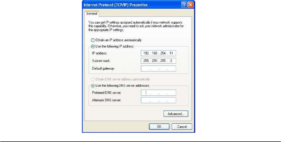
Initial Setup using the LAN Ethernet Port - Plug one end of an RJ-45 Ethernet cable to the LAN RJ-45
Ethernet port of the 3e–523 and the other end to an Ethernet port on your laptop. In order to connect
properly to the 3e–523 on the LAN port, the TCP/IP parameters on your laptop must be set to a static IP
address. Go to your network connection settings and modify your LAN connection TCP/IP properties.
Set the IP address and subnet mask. The IP address can be in the range of 192.168.254.xxx, where xxx
can be from 2 to 253 (see Figure 1).
Figure 1 - Internet Protocol Properties
AirGuard WiMesh 3e-523 Series User’s Guide
Copyright 2015 Ultra Electronics, 3eTI
October 2015
11
29000169-005 Revision C1
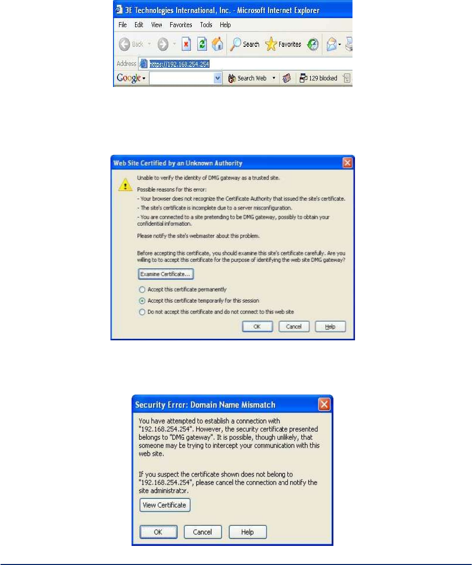
Now you can open a browser and connect to the 3e–523 to begin configuring the unit.
Login - On your computer, pull up a browser window and put the default URL for the3e–523 Local LAN in
the address line (Figure 2).
https://192.168.254.254
Figure 2 - Login
A warning window appears stating that it is unable to verify the identity of DMG gateway as a trusted site.
Select "Accept this certificate temporarily for this session" and click Ok (Figure 3).
Figure 3 - Web site certification
Another security window pops open. Click Ok to continue (Figure 4).
Figure 4 - Security window
AirGuard WiMesh 3e-523 Series User’s Guide
Copyright 2015 Ultra Electronics, 3eTI
October 2015
12
29000169-005 Revision C1
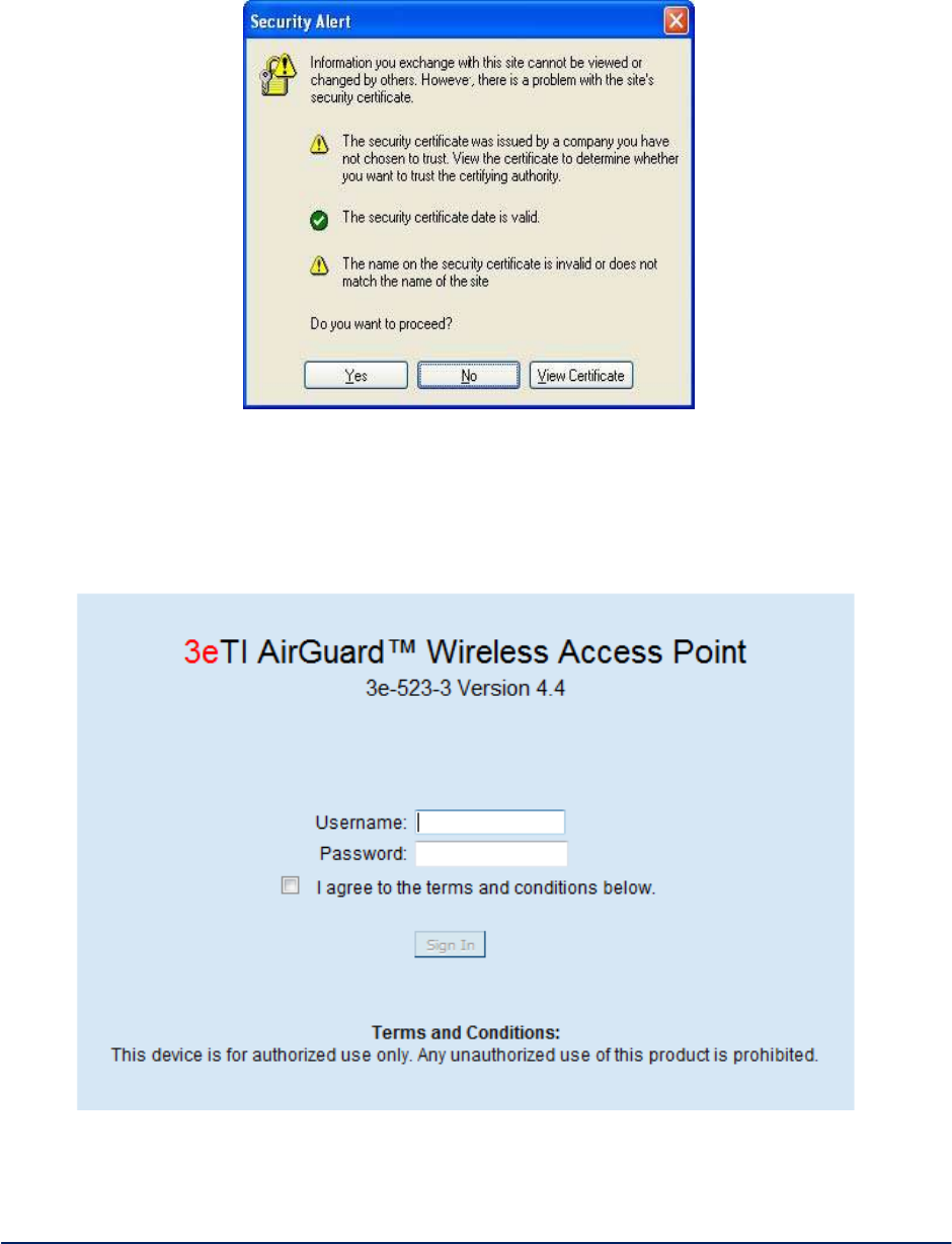
A standard security alert window (Figure 5) appears. Click Yes to continue.
Figure 5 - Security alert window
The Device Login window appears (Figure6).
You will be asked for your User Name and Password. The default is "CryptoOfficer" with the password
"CryptoFIPS" to give full access for setup configuration. (This user name and password is case-sensitive.)
Figure6–Login
NOTE: If your login session is in-active for more than 10 minutes, then you will have to re-authenticate
your identity. If after three times you fail to re-authenticate then your account will be locked. The exception

AirGuard WiMesh 3e-523 Series User’s Guide
Copyright 2015 Ultra Electronics, 3eTI
October 2015
13
29000169-005 Revision C1
is if you are the last active CryptoOfficer on the system, then your account will not be locked. The Admin
User Management - List All Users screen displays account status. If an account is locked, it will show a
status of "Locked" and a reason of "bad passwd". Other accounts show status as "Active" and reason
"Normal".
The CryptoOfficer is the only role that can unlock an account once it has been locked. Go to the Admin
User Management - List All Users screen and click the unlock button at the end of the user entry.
Data Point Configuration and Operating Modes - To begin configuration of the 3e-523 Data Points you
first must select the mode of operation. 3e-523 devices can operate in one of four different modes. Valid
operating modes are provided in the following list below:
Standalone Access Point operation.
Standalone Bridge operation.
Mixed Access Point and Bridge operation.
Client only operation.
The following subsections how to configure and operate 3e-523 Data Points.
2.2 System Configuration
There are six options under System Configuration:
General
Operating Mode
System Deployment
WAN
Serial Port
WLAN QoS/WMM
Each screen is described in detail in the following subsections.
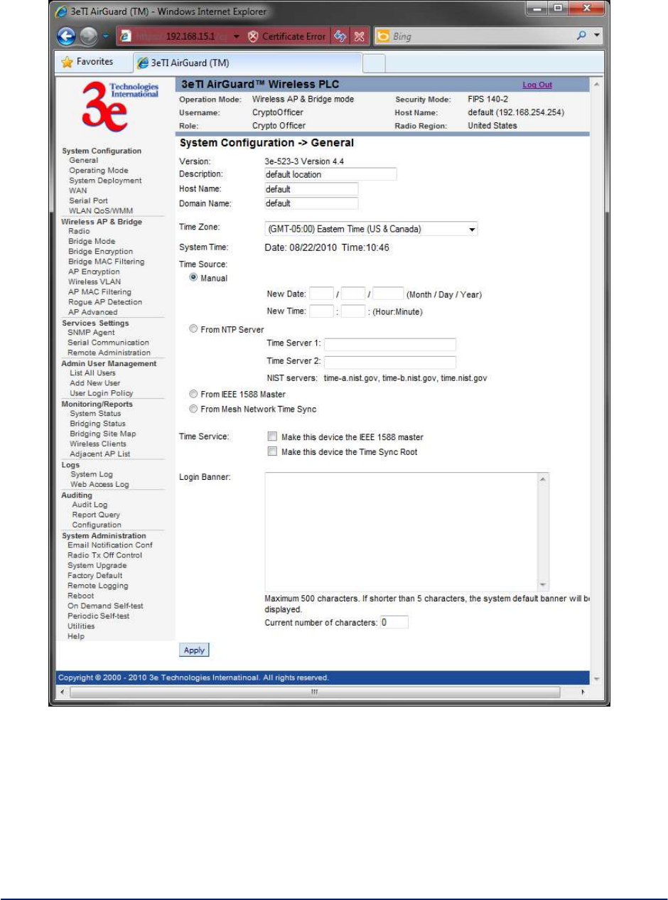
2.2.1 General
Upon access the 3e-523 web GUI, you will immediately be directed to the System Configuration -
General screen(
Figure 7).
This screen lists the firmware version number for your unit and allows you to set the Host Name and
Domain Name as well as establish system date and time. (Host and Domain Names are both set at the
factory for “default” but can optionally be assigned a unique name for each.) To set the date and time, you
can do it manually or set it based on the NTP server.
NOTE: The CryptoOfficer is the only user who can set the date and time. The system date must be set to a
date after 01/01/2005.
In the Description field you can enter a description of the physical location of the unit. This is useful when
deploying units to remote locations. When you are satisfied with your changes, click Apply.
AirGuard WiMesh 3e-523 Series User’s Guide
Copyright 2015 Ultra Electronics, 3eTI
October 2015
14
29000169-005 Revision C1
Figure 7 - System Configuration – General
Next go next to the System Configuration - Operating Mode page.
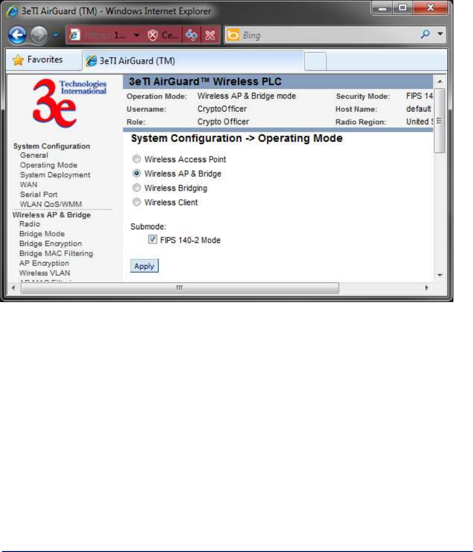
2.2.2 Operating Mode
This screen (Figure 8) allows you to set the operating mode to one of the following:
Wireless Access Point
Wireless Access Point & Bridge
Wireless Bridge
AirGuard WiMesh 3e-523 Series User’s Guide
Copyright 2015 Ultra Electronics, 3eTI
October 2015
15
29000169-005 Revision C1
Wireless Client
You only need to visit this page if you will be changing modes, or if you want to change your sub mode
Note that if you change modes your configuration will be preserved. If you switch between FIPS 140-2 sub
mode and non-FIPS, all previously entered information will be reset to factory settings for the selected
wireless mode.
Figure 8 - System Configuration - Operating Mode
Sub mode
There are two options under Sub mode:
FIPS 140-2 Mode
Use IPv6 Mode
To use the 3e–523 in FIPS 140-2 mode, or in IPv6 mode, check the box and click Apply.

AirGuard WiMesh 3e-523 Series User’s Guide
Copyright 2015 Ultra Electronics, 3eTI
October 2015
16
29000169-005 Revision C1
2.2.3 System Deployment
The unit is programmed at the factory with the customer's country code. The country code (region) is
read-only. The channel list and transmit power varies from region to region based on each country's
regional regulations (see Figure 9).
Figure 9 - System Configuration - System Deployment
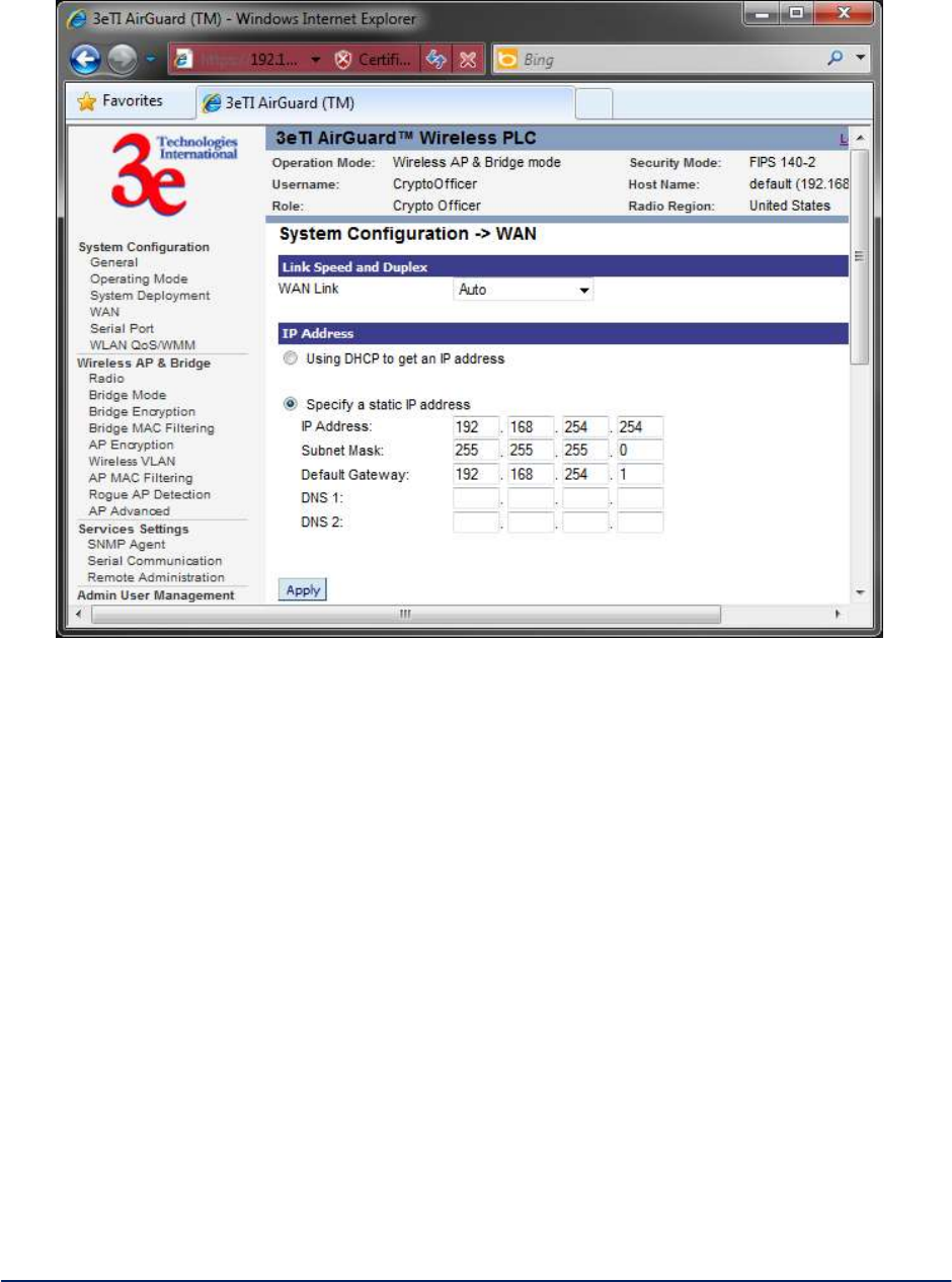
2.2.4 WAN
Click the entry on the left hand navigation panel for System Configuration - WAN. This directs you to the
System Configuration - WAN screen (Figure 10).
If not using DHCP to get an IP address, input the static IP information that the access point requires in
order to be managed from the wired LAN. This will be the IP address, Subnet Mask, Default Gateway, and,
where needed, DNS 1 and 2.
Click Apply to accept changes.
AirGuard WiMesh 3e-523 Series User’s Guide
Copyright 2015 Ultra Electronics, 3eTI
October 2015
17
29000169-005 Revision C1
Figure 10 - System Configuration - WAN
NOTE: After changing the network address you will no longer be able to access the above configuration
page with the default IP address. You will have to change the browser URL to reflect the new IP address
and log in again.
NOTE: If DHCP is selected, a new IP address would be given to the 3e–523 unit after clicking Apply. To
log into to unit and keep setting it up, the new IP address needs to be obtained from your Network Admin-
istrator. Another way to obtain the new IP address is to set up “Remote Logging” before setting up WAN
using DHCP.
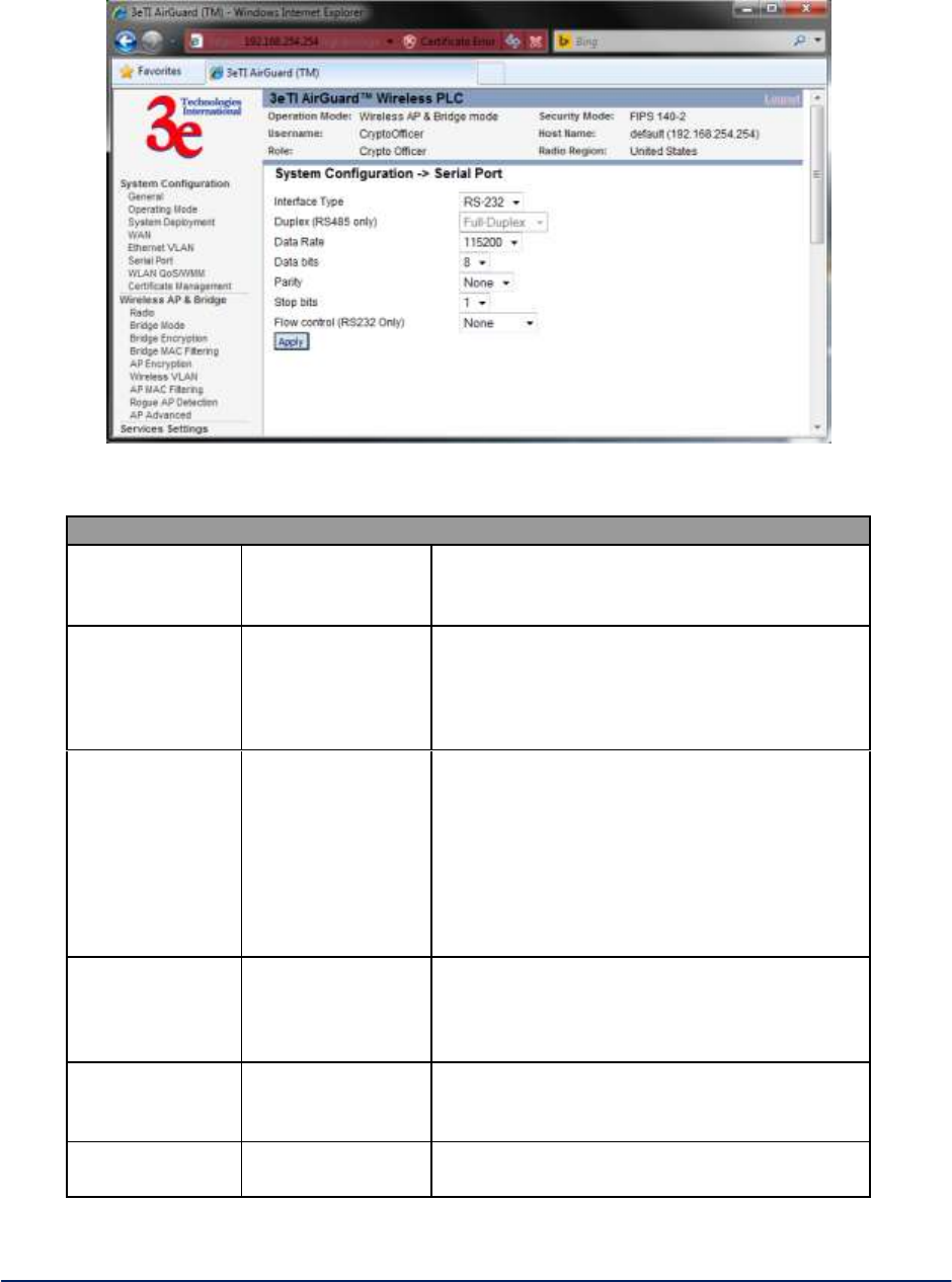
2.2.5 Serial Port
Click the entry on the left hand navigation panel for System Configuration - Serial Port (Figure 11). The
serial settings control the type and format of the serial data to be transmitted and received.
NOTE: You must also configure the settings under Services Settings - Serial Communication (Table 2)
in order for the system to work.
AirGuard WiMesh 3e-523 Series User’s Guide
Copyright 2015 Ultra Electronics, 3eTI
October 2015
18
29000169-005 Revision C1
Figure 11 - System Configuration - Serial Port
Table 2. Service Settings
Serial Settings
Interface Type
RS-232
RS-422
RS-485
Select the interface type for the serial I/O port
Duplex
(RS485 only)
Full-Duplex
Half-Duplex
For use with RS-485 interface. In full duplex
mode data is transmitted and received
simultaneously.
In half duplex mode data is transmitted or
received but not at the same time.
Data Rate
(bits per second)
115200
57600
38400
19200
9600
4800
2400
1200
Select the data rate required.
Data bits
8
7
6
5
Select the number of data bits to be transmit-
ted or received.
Parity
None
Odd
Even
Select parity to be used.
Stop bits
1
2
Select number of stop bits to be used.
AirGuard WiMesh 3e-523 Series User’s Guide
Copyright 2015 Ultra Electronics, 3eTI
October 2015
19
29000169-005 Revision C1
Serial Settings
Flow control
(RS232 only)
None
Hardware
For use with RS-232 interface. When
hardware flow control is selected, RTS and
CTS are used.
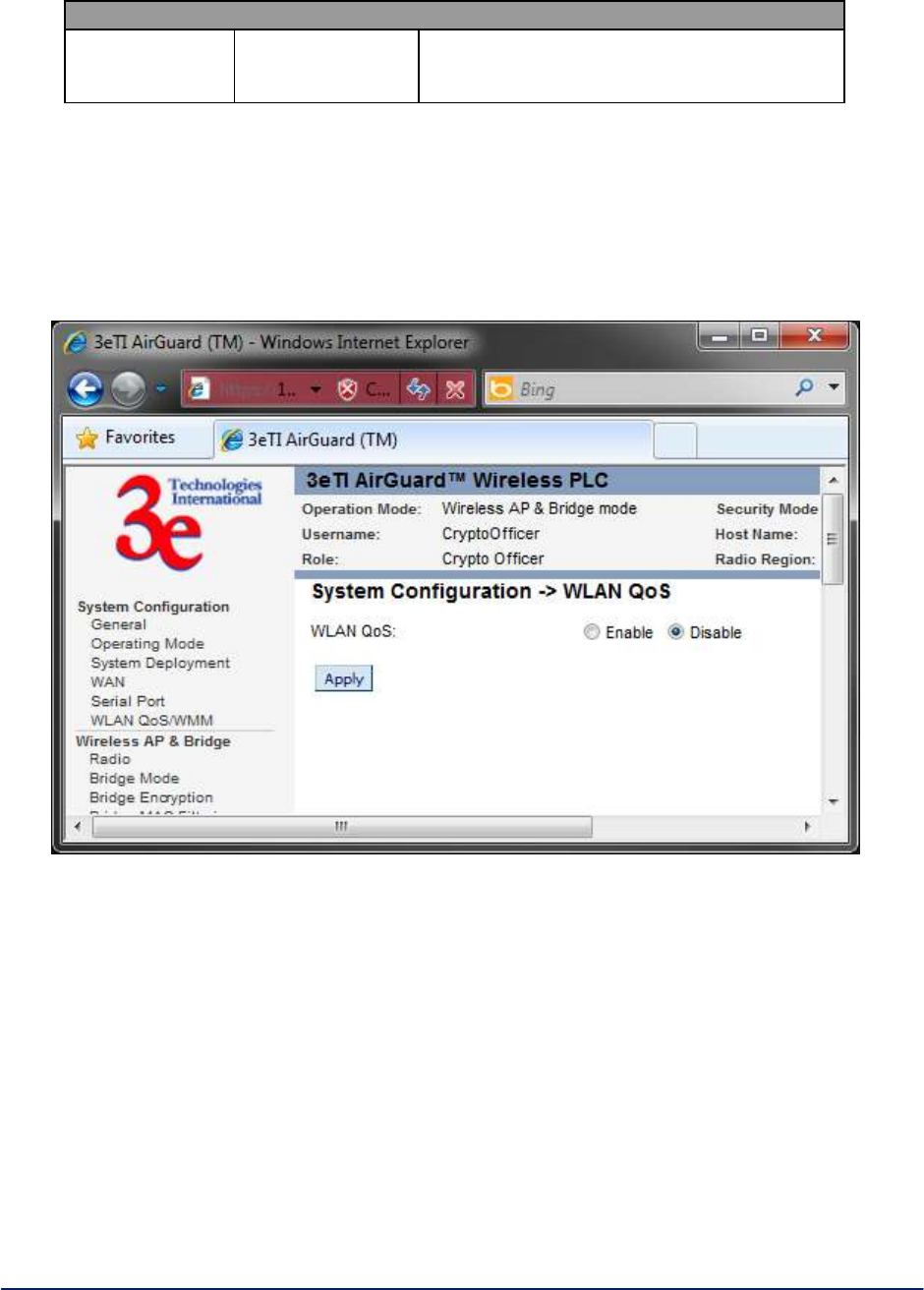
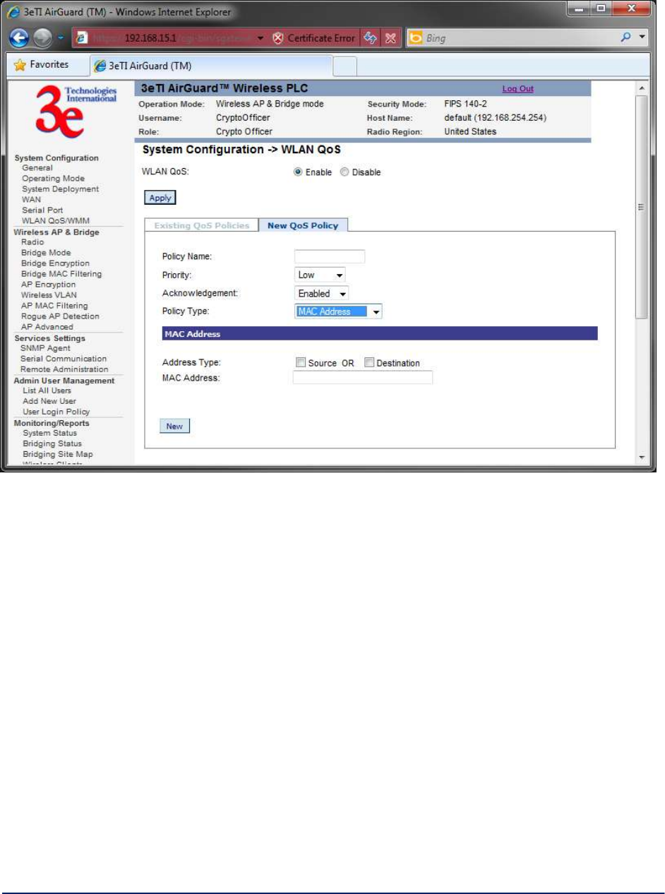
2.2.6 WLAN QoS/WMM
The unit has a Quality of Service (QoS) / Wireless Multi-Media (WMM) capability (Figure 12). The
QoS/WMM feature default is set to disable.
Figure 12 - System Configuration - WLAN QoS
If QoS is enabled, all traffic passing through the unit will be prioritized into four queues (low, normal,
medium, high). The traffic can be prioritized by MAC/IP/TCP/UDP/port, etc. The 802.1d BPDU is honored
the highest priority without further configuration.
If a traffic pattern matches more than one rule in the policies configured, the highest priority among these
rules is used. If a traffic pattern does not match any of the configured policies, then the priority is set to
normal.
There are four policy types to choose from:
Application This is a layer 4 (transportation layer) policy.
IP address This is a layer 3 (network layer) policy.
MAC address This is a layer 2 (link layer) policy.
Ethernet protocol This is a layer 2 (link layer) policy.
Click on the New QoS Policy tab to configure your QoS policies.
AirGuard WiMesh 3e-523 Series User’s Guide
Copyright 2015 Ultra Electronics, 3eTI
October 2015
20
29000169-005 Revision C1
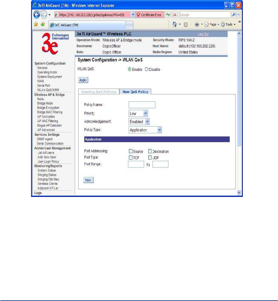
Create a policy name
Select your priority level from the drop-down list
Either enable or disable weather your want an 802.11 acknowledgement. For sensitive data packet loss,
(e.g., file transfer), "Enable" is recommended. For less sensitive, non-critical, packet loss (e.g., video),
"Disable" is recommended
Select a policy type from the drop-down list and configure the policy fields
The following screens (Figure 13, Figure 14, Figure 15, Figure 16, and Figure 17) show policy set ups
based on type.
Figure 13 - Application Policy Type
AirGuard WiMesh 3e-523 Series User’s Guide
Copyright 2015 Ultra Electronics, 3eTI
October 2015
21
29000169-005 Revision C1
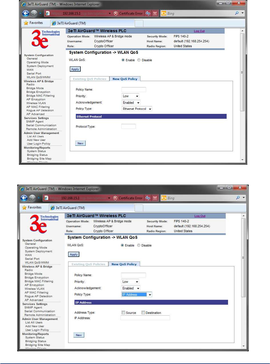
Figure 14 - Ethernet Protocol Policy Type
Figure 15 - IP Address Policy Type
AirGuard WiMesh 3e-523 Series User’s Guide
Copyright 2015 Ultra Electronics, 3eTI
October 2015
22
29000169-005 Revision C1
Figure 16 - MAC Address Policy Type
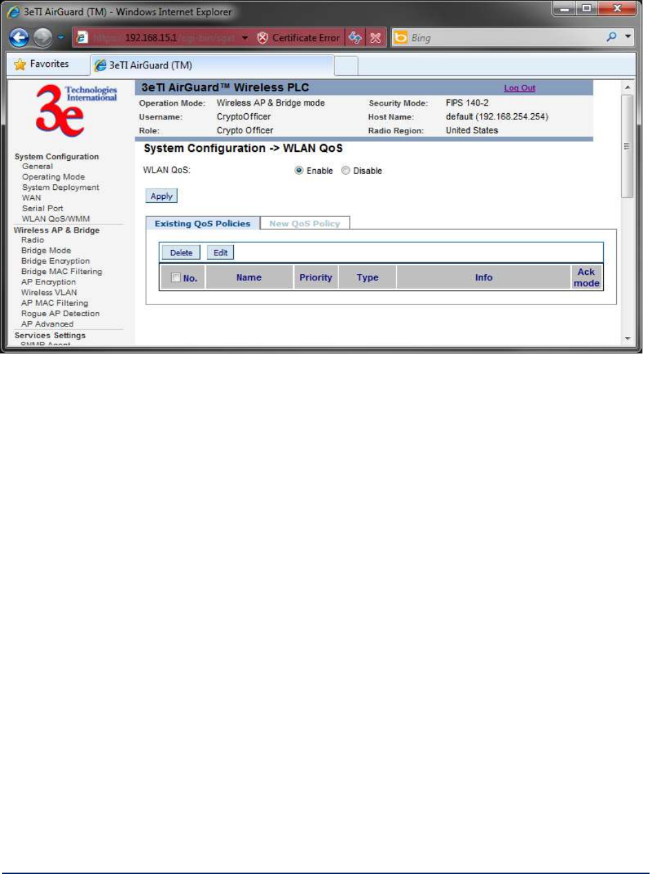
To view any existing QoS policies, click on the "Existing QoS Policies" tab.
AirGuard WiMesh 3e-523 Series User’s Guide
Copyright 2015 Ultra Electronics, 3eTI
October 2015
23
29000169-005 Revision C1
Figure 17 - Existing QoS Policies
2.3 Wireless AP and Bridge Mode
The following subsections describe the screens used when configuring the access point and bridge.
The following screens are available in Wireless AP & Bridge mode:
Radio
Bridge Mode
Bridge Encryption
Bridge MAC Filtering
AP Encryption
AP MAC Filtering
Rogue AP Detection
AP Advanced
VLAN
All other screens are the same as those described in the Client Mode section.
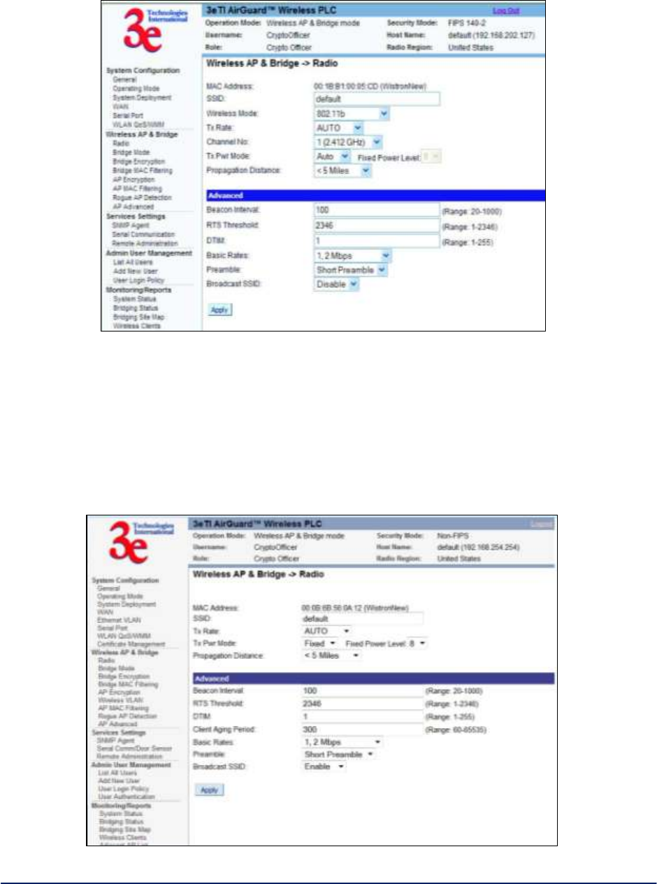
2.3.1 Radio Configuration for 3e-523A, 3e-523S and 3e-523M
The Wireless AP & Bridge - Radio screen (Figure 18) contains wireless bridging information including the
channel number, Tx rate, Tx power, spanning tree protocol (802.1d) enable/disable, and remote device's
BSSID. This page is important in setting up your access point and bridging configurations. Table 3 below
lists the various radio settings.
AirGuard WiMesh 3e-523 Series User’s Guide
Copyright 2015 Ultra Electronics, 3eTI
October 2015
24
29000169-005 Revision C1
Figure 18 - Wireless AP & Bridge — Radio
2.3.2 Radio Configuration for 3e-523E-900
The Wireless AP and Bridge - Radio screen (shown in Figure 19, below) for the Model 3e-523E-900
contains wireless bridging information including Tx rate, Tx power mode and level, as well as advanced
configuration options such as Beacon Interval and RTS Threshold. This page is important in setting up
your access point and bridging configurations. Table 3 below lists the various radio settings.
Figure 19 – 3e-523E-900 AP and Bridge -- Radio

AirGuard WiMesh 3e-523 Series User’s Guide
Copyright 2015 Ultra Electronics, 3eTI
October 2015
25
29000169-005 Revision C1
Table 3 - Radio Settings
Radio Settings
Wireless Mode
(option is not
available on the
3e-523E-900.)
802.11b/g Mixed
802.11a
802.11a Turbo
Sets the wireless mode for the wireless
bridge.
Note: If the device is enabled with 4.9GHz
sub-band, you will have two more
options:
4.9G Federal
4.9G Public Safety
Tx Rate
802.11b/g Mixed
AUTO, 1, 2, 5.5, 11, 6, 9,
12, 18, 24, 36, 48, 54 Mbps
(only some of these are
available for the
3e-523E-900)
When set to AUTO, the card attempts to
select the optimal rate for the channel.
If a fixed rate is used, the card will only
transmit at that rate.
802.11a
AUTO, 6, 9, 12, 18, 24, 36,
48, 54 Mbps
When set to AUTO, the card attempts to
select the optimal rate for the channel.
If a fixed rate is used, the card will only
transmit at that rate.
802.11a Turbo
AUTO
The card attempts to select the optimal
rate for the channel.
Channel Number
(dependent on the
radio country code
configured; option
is not available on
the 3e-523E-900.)
802.11b/g Mixed
1 (2.412 GHz)
2 (2.417 GHz)
3 (2.422 GHz)
4 (2.427 GHz)
5 (2.432 GHz)
6 (2.437 GHz)
7 (2.442 GHz)
8 (2.447 GHz)
9 (2.452 GHz)
10 (2.457 GHz)
11 (2.462 GHz)
Sets the channel frequency for the
wireless bridge.
802.11a
52 (5.26 GHz)
56 (5.28 GHz)
60 (5.30 GHz)
64 (5.32 GHz)
149 (5.745 GHz)
153 (5.765 GHz)
157 (5.785 GHz)
161 (5.805 GHz)
165 (5.825 GHz)
Sets the channel frequency for the
wireless bridge.

AirGuard WiMesh 3e-523 Series User’s Guide
Copyright 2015 Ultra Electronics, 3eTI
October 2015
26
29000169-005 Revision C1
Radio Settings
802.11a Turbo
50 (5.25 GHz)
58 (5.29 GHz)
152 (5.76 GHz)
160 (5.80 GHz)
Sets the channel frequency for the
wireless bridge.
Tx Pwr Mode
OFF FIXED, AUTO
The Tx Pwr Mode defaults to AUTO,
giving the largest range of radio
transmission available under ambient
conditions.
The wireless bridge's broadcast range
can be limited by setting the Tx Pwr
Mode to Fixed and choosing from 1-8 for
Fixed Pwr Level.
If you want to prevent any radio
frequency transmission from the wireless
bridge, set the Tx Pwr Mode to OFF. This
will not turn off RF transmissions from
any associated wireless devices, but they
will not be able to communicate with the
wireless bridge when the Tx Pwr Mode is
off.
Fixed Pwr Level
1, 2, 3, 4, 5, 6, 7, 8
(3e-523E-900 transmit
power options which start at
4.)
Select a range when Tx Pwr Mode is set
to FIXED. Level 1 is the shortest
distance, and Level 8 is the longest.
Propagation
Distance
< 5 Miles
5-10 Miles
11-15 Miles
16-20 Miles
21-25 Miles
26-30 Miles
> 30 Miles
(not changeable for the
3e-523E-900.)
Set the distance based on the space
between this bridge and furthest bridge
that is connected to it.
RTS Threshold
Range 1-2346
The number of bytes used for the
RTS/CTS handshake boundary. When a
packet size is greater than the RTS
threshold, the RTS/CTS handshaking is
performed.
Beacon Interval
20-1000
The time interval in milliseconds in which
the 802.11 Beacon is transmitted by the
bridge.
BSSID
Enter hexadecimal numbers
Add the MAC address of the remote
bridge. The remote bridge's MAC
address will appear at the bottom of the
screen.
Note
You can enter a note that defines the
location of the remote bridge.
AirGuard WiMesh 3e-523 Series User’s Guide
Copyright 2015 Ultra Electronics, 3eTI
October 2015
27
29000169-005 Revision C1
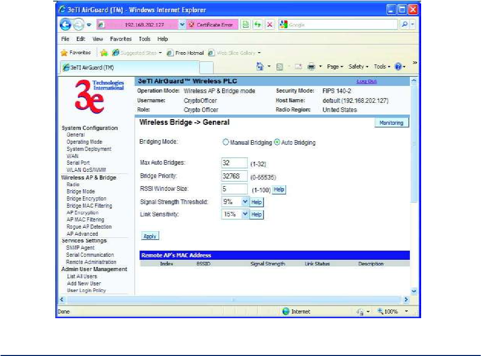
2.3.3 Bridge Mode
The Wireless Bridge - General screen (Figure 20) contains wireless bridging information. This page is
important in setting up your bridge configuration.
Table 4 lists the various auto bridging setting options. Wireless bridging supports two modes of
operation:
Manual wireless bridging
Auto-forming wireless bridging (AWB) - with a maximum number of allowable bridges (the default
is 32)
Auto-forming Wireless Bridging - When the wireless bridge is in auto-forming mode, the wireless bridge
sniffs for beacons from other wireless bridges and identifies devices that match a policy such as SSID and
channel.
Instead of simply adding the devices with the same SSID/channel to the network, a three-way association
handshake is performed in order to control network access.
To make a unit the root (leaf) STP node, set the bridge priority lower than any other node in the network.
Figure 20 - Wireless Bridge — General

AirGuard WiMesh 3e-523 Series User’s Guide
Copyright 2015 Ultra Electronics, 3eTI
October 2015
28
29000169-005 Revision C1
Table 4 - Auto Bridging General Settings Options
Auto Bridging General Settings Options
Bridging Mode
Auto Bridging
auto bridging selected
SSID
numbers or letters
Can be any set of letters and
numbers assigned by the network
administrator. This nomenclature
has to be set on the wireless
bridge and each wireless device
in order for them to communicate.
Max Auto
Bridges
1-32
Maximum number of auto bridges
allowed.
Bridge Priority
1-65535
Determines the root (leaf) STP
node. The lowest bridge priority
in the network will become the
STP root.
RSSI Window
Size
1-100
RF signal fluctuates over time
and the fluctuation varies in
different operating environments.
This parameter serves to smooth
RSSI. The RSSI that applications
use will be an average of last
window-size RSSI samples. The
sampling rate depends on the
beacon interval of the neighbor
mesh node. This helps stabilize
the network. For fixed location
deployment, higher values are
suggested for both window size
and beacon interval. Lower value
is recommended while adjusting
antenna or distributing mobile
mesh devices.
Signal Strength
Threshold
75%
60%
51%
45%
39%
27%
21%
15%
9%
None
On creating a bridge link, if the
signal strength is less than this
threshold, the link will not be
created. After a link is created, it
will not be destroyed even after
the signal goes below this
threshold. This helps to stabilize
the network.

AirGuard WiMesh 3e-523 Series User’s Guide
Copyright 2015 Ultra Electronics, 3eTI
October 2015
29
29000169-005 Revision C1
Auto Bridging General Settings Options
Link Sensitivity
75%
60%
51%
45%
39%
27%
21%
15%
9%
None
After a link is created, signal
strength is mapped to RSTP path
cost. Because RF signal
fluctuates, path cost needs to be
adjusted accordingly. However,
adjusting path cost too frequently
will cause network instability. This
field serves as a threshold to
adjust path cost.
Path cost is adjusted if signal
strength increases/decreases by
this value since the last
adjustment. If the value is set to
none, every link acts like 100%
signal and there will be no path
cost adjustment later on. It is
strongly recommended that the
same value is set on all other
nodes in the same network.
Broadcast
SSID
Disable/Enable
When disabled, the AP hides the
SSID in outgoing beacon frames
and stations cannot obtain the
SSID through passive scanning.
Also, when it is disabled, the
bridge doesn’t send probe
responses to probe requests with
unspecified SSIDs.
Signal Strength
MAC
The signal strength of this
wireless bridge will be indicated
on the Signal Strength LED
located on the front of the case.
Remote AP's
MAC Address
Read Only
Displays the BSSID of remote
bridges that were added on the
Wireless Bridge - Radio screen.
Manual Bridging - When the wireless bridge is in manual bridging mode (Figure 21), you can manually
select a signal strength LED MAC and enable or disable spanning tree protocol. You can also delete
remote AP's MAC addresses. Table 5 lists the various manual bridging settings.

AirGuard WiMesh 3e-523 Series User’s Guide
Copyright 2015 Ultra Electronics, 3eTI
October 2015
30
29000169-005 Revision C1
Figure 21 - Wireless Bridge - Manual Bridging
Table 5 - Manual Bridging General Settings Options
Manual Bridging General Settings Options
Bridging Mode
Manual Bridging
manual bridging selected
Signal Strength
LED MAC
Not Assigned
Allows you to set the number of the
remote AP which will be listed at the
bottom of the screen once the
system is operational This wireless
bridge becomes the guiding port
that is displayed in the WLAN LED
on the front of the 523–3 and
3e-523-F1 as a signal.
Spanning Tree
Protocol (STP)
Enable/Disable
Enable STP if there is any
possibility that a bridging loop could
occur. If you are certain that there is
no possibility that a bridging loop
will occur, then disable STP. The
bridge will be more efficient (faster)
without it. If you are not sure, the
safest solution is to enable STP.
Remote AP's
MAC Address
Read Only
Displays the BSSID of remote
bridges that were added on the
Wireless Bridge - Radio screen.
AirGuard WiMesh 3e-523 Series User’s Guide
Copyright 2015 Ultra Electronics, 3eTI
October 2015
31
29000169-005 Revision C1
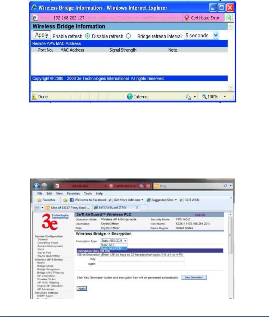
Monitoring - In the upper right-hand corner of the Wireless Bridge - General screen there is a button
called Monitoring (Figure 22). If you click on this button, a pop-up window will appear (WDS Information). If
you select Enable refresh, you can set the bridge refresh interval from 5 seconds to 30 minutes.
Refreshing the screen allows you to see the effect of aiming the antenna to improve signal strength.
Figure 22 - Wireless Bridge - Monitoring
2.3.4 Bridge Encryption
The Wireless Bridge - Encryption screen (Figure 23) is used to configure static encryption keys for the
wireless bridge. This is an important page to set up to ensure that your bridge is working correctly. The
encryption key that you use on this screen must be the same for any bridge connected to your bridging
network in order for communication to occur. On this screen you can select Static AES (128-bit, 192-bit, or
256-bit) or AES-CCM (128-bit)
Figure 23 - . Wireless Bridge – AES-CCM Encryption

AirGuard WiMesh 3e-523 Series User’s Guide
Copyright 2015 Ultra Electronics, 3eTI
October 2015
32
29000169-005 Revision C1
Static AES Key - The Advanced Encryption Standard (AES) was selected by National Institute of
Standards and Technology (NIST) in October 2000 as an upgrade from the previous DES standard. AES
uses a 128-bit block cipher algorithm and encryption technique for protecting computerized information.
With the ability to use even larger 192-bit and 256-bit keys, if desired, it offers higher security against
brute-force attack than the old 56-bit DES keys (Figure 24).
The Key Generator button automatically generates a randomized key of the appropriate length. This key is
initially shown in plain text so the user has the opportunity to copy the key. Once the key is applied, the key
is no longer displayed in plain text.
Figure 24 - Wireless Bridge - Static AES
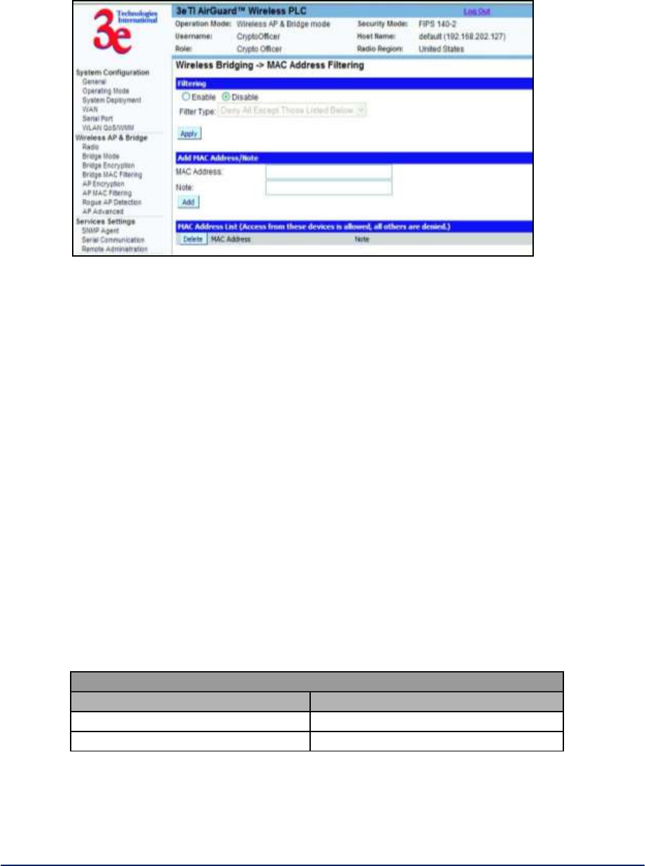
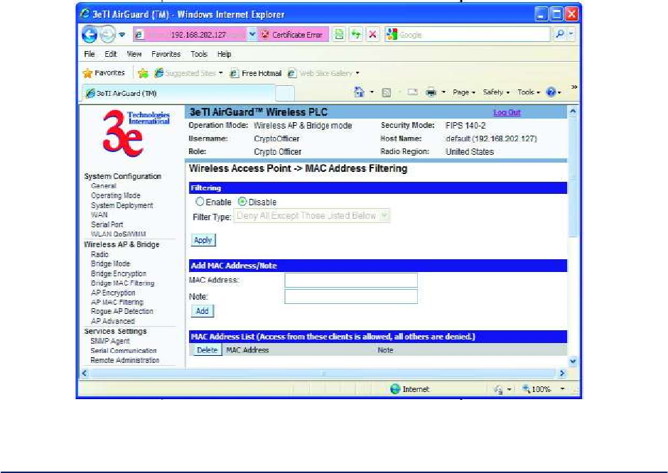
2.3.5 MAC Address Filtering
The WirelessBridge - MAC Address Filtering screen (Figure 25)is used to set up MAC address filtering
for the 3e–523 device. This option is only available in Auto Bridge Mode.
The factory default for MAC Address filtering is Disabled. If you enable MAC Address filtering, you should
also set the toggle for Filter Type.
AirGuard WiMesh 3e-523 Series User’s Guide
Copyright 2015 Ultra Electronics, 3eTI
October 2015
33
29000169-005 Revision C1
Figure 25 - Wireless Bridge - MAC Address Filtering
This works as follows:
If Filtering is enabled and Filter Type is Deny All Except Those Listed Below, only those
devices equipped with the authorized MAC addresses will be able to communicate with the
3e–523. In this case, input the MAC addresses of all the remote bridging units that will be
authorized to access this 3e–523. The MAC address is engraved or written on the PC (PCMCIA)
Card.
If Filtering is enabled and Filter Type is Allow All Except Those Listed Below, those devices
with a MAC address which has been entered in the MAC Address listing will NOT be able to
communicate with the 3e–523. In this case, navigate to the report: Wireless Clients and copy the
MAC address of any Wireless Client that you want to exclude from communication with the
3e–523 and input those MAC Addresses to the MAC Address list.
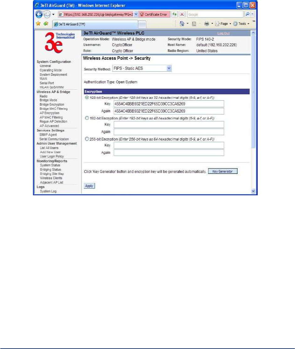
2.3.6 AP Encryption
The Access Point - Encryption screen displays a default factory setting of no encryption, but for security
reasons it will not communicate to any clients unless the encryption is set by the CryptoOfficer. There are
different encryption options for the AP in FIPS Mode and in non-FIPS Mode. Table 6 below shows the
differences.
Table 6 - Encryption Options
Encryption Options
In FIPS 140-2 Mode
In non-FIPS AP Mode
FIPS Static AES
Static WEP
FIPS 802.11i
802.11i
In the following explanations, the FIPS Mode security options are discussed first.
Static AES Key - The Advanced Encryption Standard (AES) was selected by National Institute of
Standards and Technology (NIST) in October 2000 as an upgrade from the previous DES standard. AES
uses a 128-bit block cipher algorithm and encryption technique for protecting computerized information.
AirGuard WiMesh 3e-523 Series User’s Guide
Copyright 2015 Ultra Electronics, 3eTI
October 2015
34
29000169-005 Revision C1
With the ability to use even larger 192-bit and 256-bit keys, if desired, it offers higher security against
brute-force attack than the old 56-bit DES keys. See Figure 26.
The Key Generator button automatically generates a randomized key of the appropriate length. This key is
initially shown in plain text so the user has the opportunity to copy the key. Once the key is applied, the key
is no longer displayed in plain text.
Figure 26 - Static AES
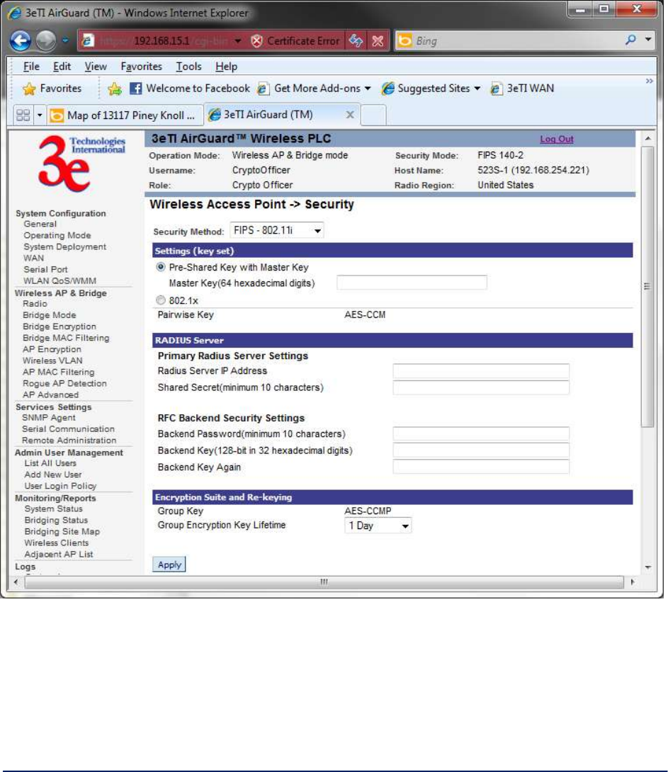
802.11i - If you wish to use 802.11i on the 3e–523, enable either Pre-shared Key Settings or 802.1x
Settings (Figure 27)
If you are a SOHO user, selecting pre-shared key means that you don’t have the expense of installing a
Radius Server. Simply input up to 63 character / numeric / hexadecimals in the Passphrase field.
Enable pre-authentication to allow a client to authenticate in advance with the AP before the client is
associated with it. Allowing the AP to pre-authenticate a client decreases the transition time when a client
roams between APs.
As an alternative, for business applications who have installed Radius Servers, select 802.1x and input the
Primary Radius Server and RFC Backend security settings. Use of Radius Server for key management
and authentication requires that you have installed a separate certification system and each client must
have been issued an authentication certificate.
AirGuard WiMesh 3e-523 Series User’s Guide
Copyright 2015 Ultra Electronics, 3eTI
October 2015
35
29000169-005 Revision C1
Re-keying time is the frequency in which new encryption keys are generated and distributed to the client.
The more frequent re-keying, the better the security. For highest security, select the lowest re-keying
interval.
Once you have selected the options you will use, click Apply.
Figure 27 – FIPS 802.11i
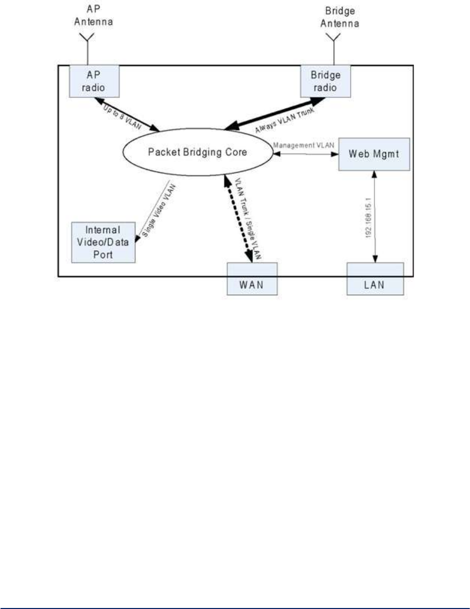
2.3.7 Wireless VLAN
Logical Internal Interfaces - In order to use the VLAN features of the 3e-523 series products correctly
and flexibly, it’s recommended that user understand the logical internals. The following provides an
overview of VLAN operation on the 3e-523 devices
Figure 28 below shows the logical internal interfaces of the “Packet Bridging Core” which bridges packets
between the logical and physical interfaces (WAN, AP, Bridge, and Management VLAN) of the 3e-523.
AirGuard WiMesh 3e-523 Series User’s Guide
Copyright 2015 Ultra Electronics, 3eTI
October 2015
36
29000169-005 Revision C1
Figure 28 - Packet Bridging Logical Internals
Note: The 3e-523 contains one radio and one Ethernet port. The radio operates in client mode, AP mode,
Bridge mode, or AP & Bridge modes. Note that client mode does not offer VLAN capability and VLAN
operation cannot be configured when operating in Client mode.
AP Virtual Interface - The AP virtual interface is available in AP mode or AP & Bridge simultaneous
mode. It can be configured to provide a maximum of 8 VLAN mappings. Each VLAN is mapped to one
SSID. Packets in the air between AP radio and wireless clients contain no VLAN tag.
Packets from a wireless client associated with a given SSID are VLAN tagged by the AP radio, according
to the configuration mapping between SSID and VLAN. The tagging happens before packets enter the
“Packet Bridging Core.”
VLAN tags, in packets received from the WAN interface and to be transmitted to wireless clients
associated with the AP radio, are removed before the packets are transmitted to the clients.
Bridge Virtual Interface - The bridge virtual interface is available in Bridge or AP & Bridge mode. The
bridge virtual interface always acts as VLAN trunk. Packets in and out from bridge radio are sent
unmodified. So there’s no VLAN related configuration for the bridge virtual interface.
AirGuard WiMesh 3e-523 Series User’s Guide
Copyright 2015 Ultra Electronics, 3eTI
October 2015
37
29000169-005 Revision C1
WAN Virtual Interface - Since the 3e-523 has one Ethernet port, both the WAN and LAN logical interfaces
map to the Ethernet physical interface. IP/ARP packets with a fixed target IP address of 192.168.15.1 are
always redirected to LAN virtual interface. All other packets go to WAN virtual interface.
The WAN virtual interface always acts as VLAN trunk. Packets in and out from bridge radio are sent
unmodified. So there’s no VLAN related configuration for WAN virtual interface.
Web Management - Web management traffic from non-local port is on management VLAN. Packets
originated from web management server are tagged with management VLAN before they reach “Packet
Bridging Core”. Only packets with management VLAN tag can be forwarded by “Packet Bridging Core” to
web management server and the VLAN tags are removed before they reach web management server.
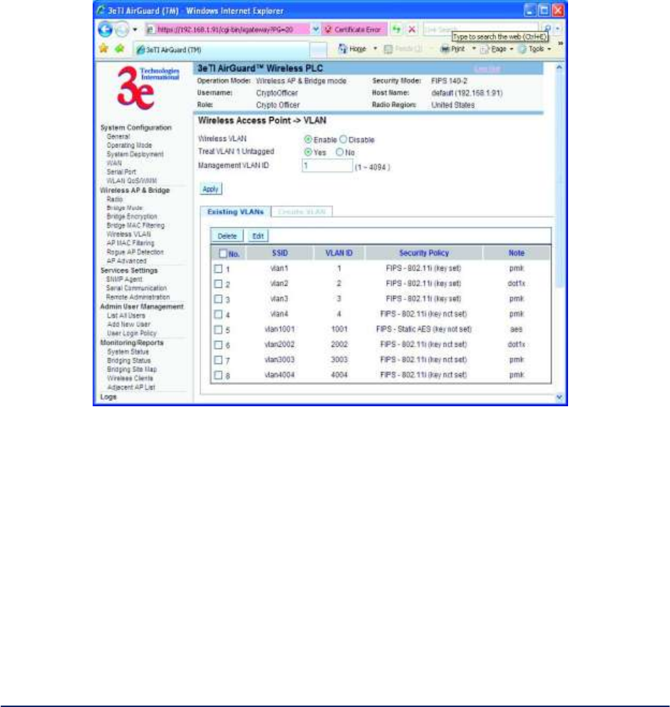
Figure 29 - VLAN Configuration GUI Overview
Figure 29 above shows the web GUI configuration for 2 out of 4 interfaces listed in 1 “Logical Internal.” The
“bridge virtual interface” and “WAN virtual interfaces” always work in VLAN trunk mode, therefore, there’s
no VLAN related configuration for these two interfaces.
The bottom half part shows the SSID to VLAN mappings as well as the security policies assigned to each
VLAN.
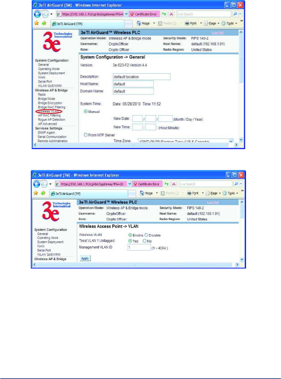
VLAN Configuration Detail - To enable the VLAN feature, click Wireless VLAN link on left menu (Figure
30, and Figure 31 below).
AirGuard WiMesh 3e-523 Series User’s Guide
Copyright 2015 Ultra Electronics, 3eTI
October 2015
38
29000169-005 Revision C1
Figure 30 - Left Menu
Figure 31 - VLAN Enable Page
To create a SSID to VLAN mapping on an AP virtual interface, click Create VLAN tab on the Wireless
VLAN page after enabling the Wireless VLAN option (Figure 32 and Figure 33).

AirGuard WiMesh 3e-523 Series User’s Guide
Copyright 2015 Ultra Electronics, 3eTI
October 2015
39
29000169-005 Revision C1
Figure 32 - Create Wireless VLAN Tab
Figure 33 - Create Wireless VLAN Page
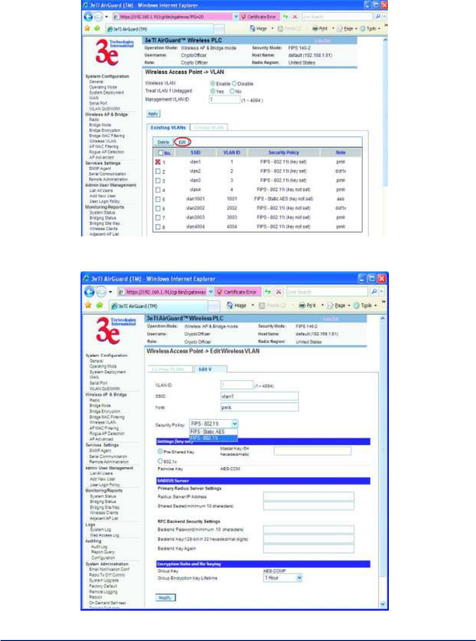
To edit an existing VLAN, select the target VLAN and then click the Edit button (Figure 34 and Figure 35)
AirGuard WiMesh 3e-523 Series User’s Guide
Copyright 2015 Ultra Electronics, 3eTI
October 2015
40
29000169-005 Revision C1
Figure 34 - Edit VLAN step 1
Figure 35 - Edit VLAN step 2
AirGuard WiMesh 3e-523 Series User’s Guide
Copyright 2015 Ultra Electronics, 3eTI
October 2015
41
29000169-005 Revision C1
NOTES & TIPS
1. Most (not all) switch vendors treat VLAN 1 as an untagged VLAN. 3eTI devices make the VLAN 1
tag rule a user option. By default, 3eTI treats VLAN 1 as an untagged VLAN. It is recommended
that users keep the same default setting for all devices in the same physical network.
2. “Treat VLAN 1 Untagged” setting is a device-wide option. The rule applies to all interfaces that are
configured to be on VLAN 1. For example, if this option is enabled, management traffic from this
device Also, wireless client traffic on VLAN 1 won’t have tag.
3. It’s always recommended to manage the device through the LAN virtual interface (192.168.15.1)
when local access is available for the device. The LAN virtual interface is helpful especially when:
o A device IP address is unknown.
o The device has not obtained an IP address from a DHCP server.
o The Management VLAN is tagged.
2.3.8 AP MAC Filtering
The Wireless Access Point - MAC Filtering screen (
Figure 36) is used to set up MAC address filtering for 3e–523 devices. The factory default for MAC
Address filtering is Disabled. If you enable MAC Address filtering, you should also set the toggle for Filter
Type.
Figure 36 - Wireless Access Point - MAC Filtering
MAC Filtering works as follows:

AirGuard WiMesh 3e-523 Series User’s Guide
Copyright 2015 Ultra Electronics, 3eTI
October 2015
42
29000169-005 Revision C1
If Filtering is enabled and Filter Type is Deny All Except Those Listed Below, only those
devices equipped with the authorized MAC addresses will be able to communicate with the access
point. In this case, input the MAC addresses of all the PC cards that will be authorized to access
this access point.
If Filtering is enabled and Filter Type is Allow All Except Those Listed Below, those devices
with a MAC address which has been entered in the MAC Address listing will NOT be able to
communicate with the access point. In this case, navigate to the report: Wireless Clients and
copy the MAC address of any Wireless Client that you want to exclude from communication with
the access point and input those MAC Addresses to the MAC Address list.
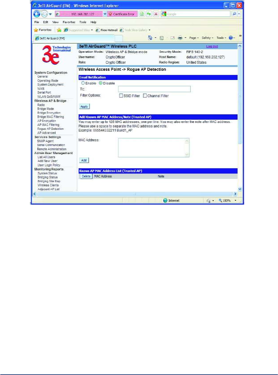
2.3.9 Rogue AP Detection
The Wireless Access Point - Rogue AP Detection screen (Figuer 37) allows the network administrator
to set up rogue AP detection. Enable rogue AP detection and enter the MAC Address of each AP in the
network that you want the AP being configured to accept as a trusted AP. (You may add up to 20 APs.)
Enter an email address for notification of any rogue or non-trusted APs. (The MAC Address for the 3e–523
is located on the System Configuration - General screen. You can also select the following filter options.
SSID Filter: Check the SSID option to only send rogue APs that match the AP's SSID or wireless
bridge's SSID.
Channel Filter: Check the channel filter option to only send rogue APs that match the AP's
channel or the wireless bridge's channel.
If both options are checked, only APs that match both the SSID and channel are sent.
The Adjacent AP list, under Monitoring/Reports on the navigation menu, will detail any marauding APs.
AirGuard WiMesh 3e-523 Series User’s Guide
Copyright 2015 Ultra Electronics, 3eTI
October 2015
43
29000169-005 Revision C1
Figure 37 - Wireless Access Point - Rogue AP Detection
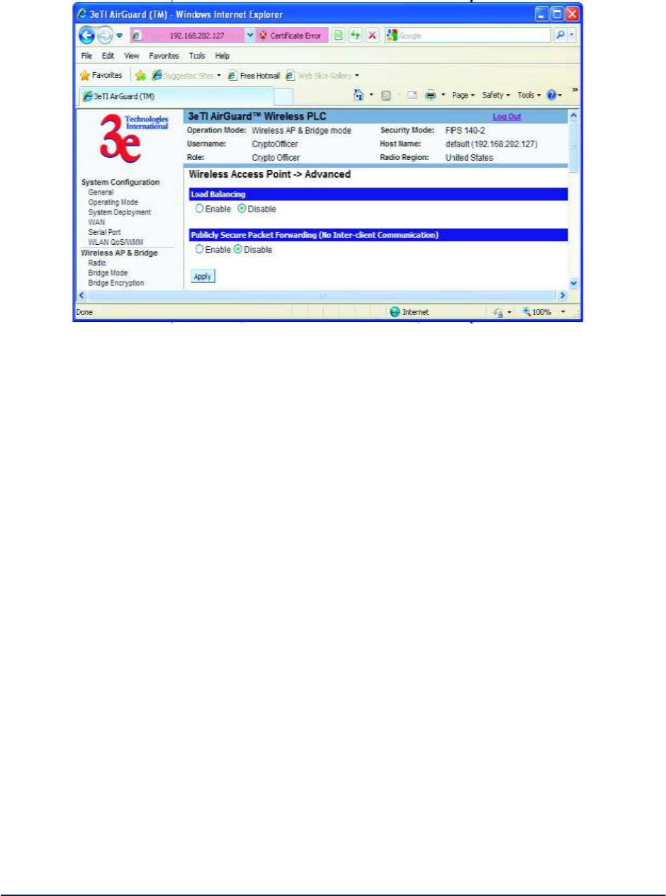
2.3.10 AP Advanced
The Wireless Access Point - Advanced screen (Fifure 38) allows you to enable or disable load balancing
and to control Publicly Secure Packet Forwarding, which provides client isolation at the Layer 2 level.
Load balancing is enabled by default. The load balancing feature balances the wireless clients between
APs. If two APs with similar settings are in a conference room, depending on the location of the APs, all
wireless clients could potentially associate with the same AP, leaving the other AP unused. Load
balancing attempts to evenly distribute the wireless clients on both APs.
Publicly Secure Packet Forwarding is disabled by default. Enabling this feature prevents wireless clients
that associate with the same AP from communicating with each other.
AirGuard WiMesh 3e-523 Series User’s Guide
Copyright 2015 Ultra Electronics, 3eTI
October 2015
44
29000169-005 Revision C1
Figure 38 - Wireless Access Point - Advanced
Once you have made any changes, click Apply to save.
2.4 Service Settings
There are two options under Service Settings:
SNMP Agent
Serial Communication
Each screen is described in detail in the following subsections.
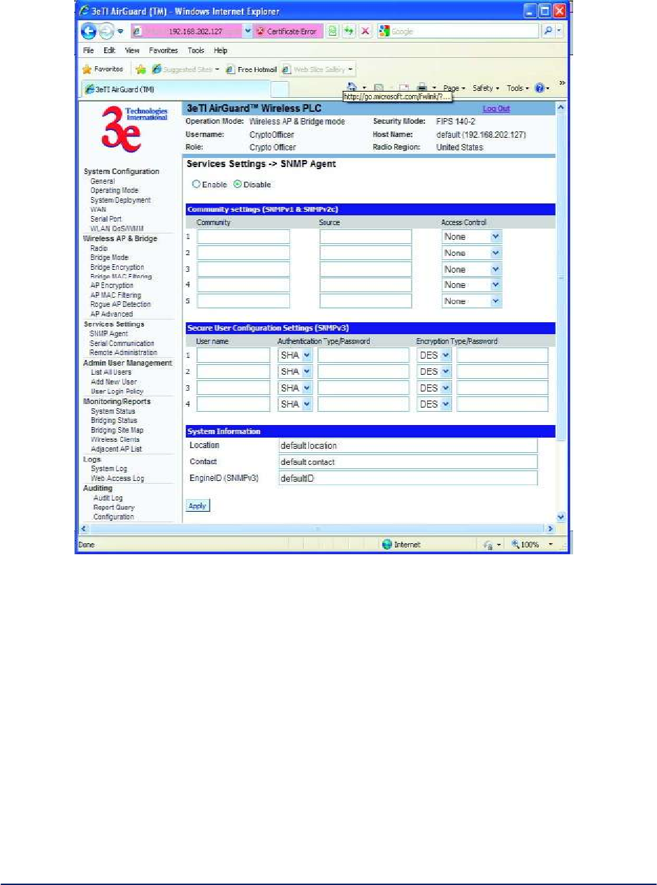
2.4.1 SNMP Agent
The Service Settings - SNMP Agent screen (Figure 39) allows you to set up an SNMP Agent. The agent
is a software module that collects and stores management information for use in a network management
system. 3e–523 devices have an integrated SNMP agent software module that translates the device’s
management information into a common form for interpretation by the SNMP Manager, which usually
resides on a network administrator’s computer.
Information is transported via SNMPv1 (Simple Network Management Protocol) or SNMPv2c, along with
the associated Management Information Base (MIB), though trap-directed notifications.
The idea behind trap-directed notification is as follows: if a manager is responsible for a large number of
devices, and each device has a large number of objects, it is impractical for him to poll or request
information from every object on every device. The solution is for each agent on the managed device to
notify the manager without solicitation. It does this by sending a message known as a trap when an
appropriate event occurs.
After receiving the event, the manager displays it and may choose to take an action based on the event.
For instance, the manager can poll the agent directly, or poll other associated device agents to get a better
understanding of the event.

AirGuard WiMesh 3e-523 Series User’s Guide
Copyright 2015 Ultra Electronics, 3eTI
October 2015
45
29000169-005 Revision C1
Trap-directed notification can result in substantial savings of network and agent resources by eliminating
the need for frivolous SNMP requests. However, it is not possible to totally eliminate SNMP polling. SNMP
requests are required for discovery and topology changes. In addition, a managed device agent can not
send a trap, if the device has had a catastrophic outage.
SNMPv1 traps are defined in RFC 1157, with the following fields:
Enterprise Identifies the type of managed object generating the trap.
Agent address Provides the address of the managed object generating the trap.
Generic trap type Indicates one of a number of generic trap types.
Specific trap code Indicates one of a number of specific trap codes.
Time stamp Provides the amount of time that has elapsed between the last network
reinitialization and generation of the trap.
Variable bindings The data field of trap containing PDU. Each variable binding associates a
particular MIB object instance with its current value.
Standard generic traps are: coldStart, warmStart, linkDown, linkUp, authenticationFailure,
egpNeighborLoss.
In the current release, 3eTI has implemented warmStart, link-Down, linkUp, and authenticationFailure 5
generic traps and transports those traps using SNMPx2, V2c Trap PDU format.
For generic SNMPv1 traps, 3eTI also redefined some generic traps (see the 3eti-trap-mibs document) by
adding some bound variables.
For example, when a trap is received for a warmStart, the receiving system will be able to see one variable
associated with this trap. The received variableName field will shows the 3eTI enterprise oid. The
varibleValue field will indicate a warmStart reason.
Additionally, a device does not send a trap to a network management system unless it is configured to do
so.
AirGuard WiMesh 3e-523 Series User’s Guide
Copyright 2015 Ultra Electronics, 3eTI
October 2015
46
29000169-005 Revision C1
Figure 39 - Service Settings - SNMP Agent
The SNMP configuration consists of several fields, which are explained below:
Community The Community field for Get (Read Only), Set (Read & Write), and Trap is
simply the SNMP terminology for “password” for those functions.
Source The IP address or name where the information is obtained.
Access Control Defines the level of management interaction permitted.
If using SNMPv3, enter a username (minimum of eight characters), authentication type with key and data
encryption type with a key. If operating in FIPS mode, only SHA and AES are supported. This configuration
information will also need to be entered in your MIB manager setup.
2.4.2 Serial Communication
The Serial Communication Settings section (Figure 40) displays the current serial port mode of
operation. One of two serial port profiles can be selected.

AirGuard WiMesh 3e-523 Series User’s Guide
Copyright 2015 Ultra Electronics, 3eTI
October 2015
47
29000169-005 Revision C1
Raw Socket - This allows serial devices connected to two 3e–523 devices to communicate across the
network. It is bidirectional, multiple uni-casting and peer-to-peer communications.
Figure 40 - Service Settings - Serial Communication
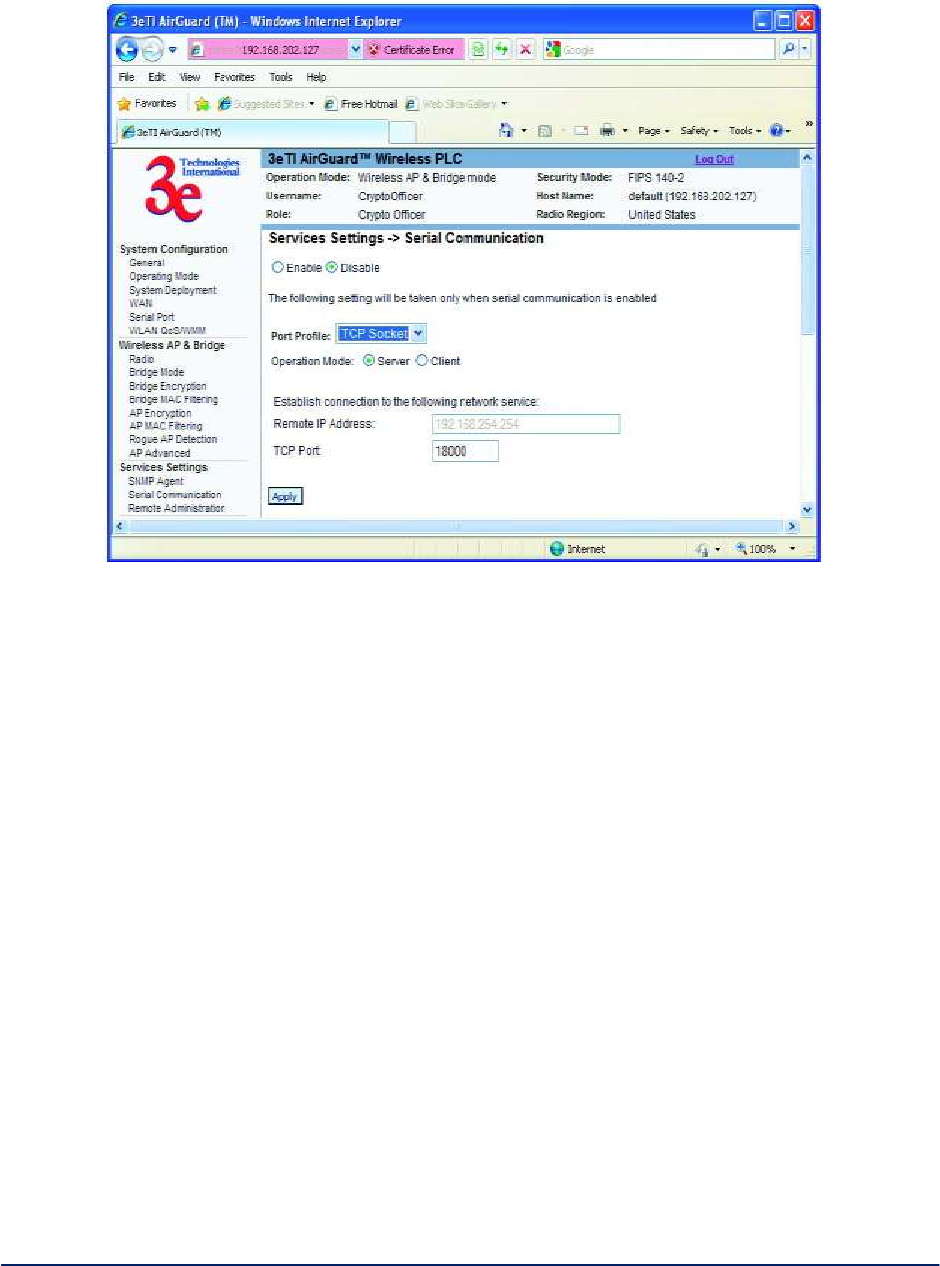
TCP Socket - It is direct IP Mode using TCP. When using TCP sockets your serial server can be
configured as a TCP server or TCP client (Figure 41).
If the 3e–523 device is configured as a TCP server, other network devices can initiate a TCP connection
with the serial device connected to the serial port. Network devices initiating connections must be
configured with the IP address of the device and the TCP port number associated with its serial port.
If the 3e–523 device is configured as a TCP client it will automatically establish a bi-directional TCP
connection between the serial device and a server or other networked device.
AirGuard WiMesh 3e-523 Series User’s Guide
Copyright 2015 Ultra Electronics, 3eTI
October 2015
48
29000169-005 Revision C1
Figure 41 - Service Settings - TCP Socket
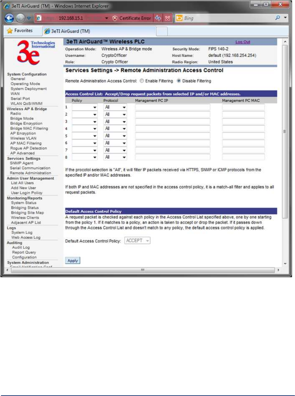
2.4.3 Remote Administration
The Service Settings – Remote Administration screen (Figure 42) allows you to set up access control
policies for remote administration via HTTPs, SNMP and ICMP protocols. In the factory default
configuration, Remote Administration Access Control option is disabled and hence remote administration
is allowed for any source IP address and MAC address.
When the Remote Administration Access Control option is enabled, the device validates the source IP
and/or MAC addresses of administrative queries and control requests to insure that the message request
is from an approved node. This enables secure remote administration from selected IP and/or MAC
addresses.
AirGuard WiMesh 3e-523 Series User’s Guide
Copyright 2015 Ultra Electronics, 3eTI
October 2015
49
29000169-005 Revision C1
Figure 42 - Service Settings – Remote Administration Access Control
2.5 Admin User Management
There are three options under Admin User Management:
List All Users
o Edit User
Add New Users
User Login Policy Each screen is described in detail in the following subsections.
AirGuard WiMesh 3e-523 Series User’s Guide
Copyright 2015 Ultra Electronics, 3eTI
October 2015
50
29000169-005 Revision C1
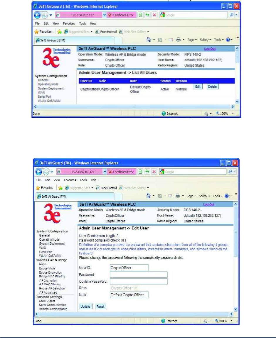
2.5.1 List All Users
The Admin User Management - List All Users screen (Figure 43) lists the Crypto Officer and
administrator accounts configured for the unit. You can edit or delete users from this screen.
Figure 43 - Admin User Management - List All Users
If you click on Edit, the Admin User Management - Edit User screen (Figure 44) appears. On this screen
you can edit the user ID, password, role, and note fields.
Figure 44 - Admin User Management - Edit User
AirGuard WiMesh 3e-523 Series User’s Guide
Copyright 2015 Ultra Electronics, 3eTI
October 2015
51
29000169-005 Revision C1
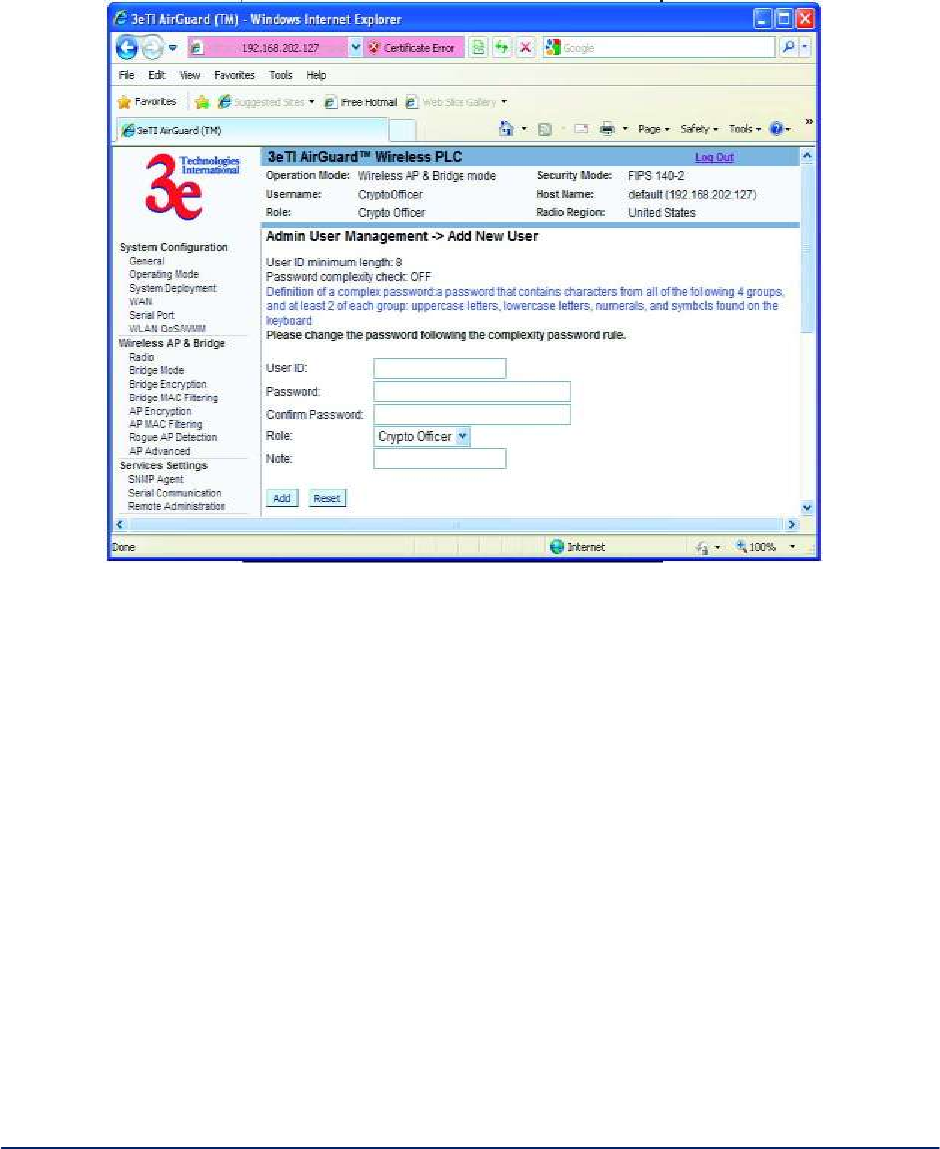
2.5.2 Add New User
The Admin User Management - Add New User screen (Figure 45) allows you to add new Administrators
and CryptoOfficers, assigning and confirming the password.
Figure 45 - Admin User Management - Add New User
The screen as shown in Figure 46 below, will appear in FIPS 140-2 mode. The Password complexity
check and the Minimal Password length are established on the Admin User Management - User
Login Policy screen.
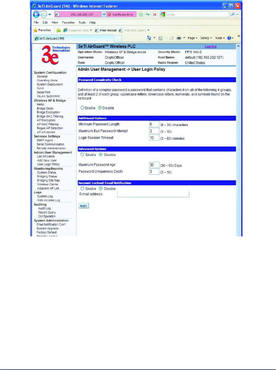
2.5.3 User Login Policy
The Admin User Management - User Login Policy screen (Figure 46) allows you to enable a Password
Complexity Check. The "User Login Policy" applies to both admin users and end-users. If an admin
account or an end-user account is locked for whatever reason, only a CryptoOfficer role user can unlock
the account from the LAN port.
The definition of a complex password is a password that contains characters from all of the following 4
groups and at least 2 of each group: uppercase letters, lowercase letters, numerals, and symbols found on
the keyboard. The minimum password length is eight (8) characters and the maximum length is 30.
The maximum password age is configurable from 30 to 90 days. The default is 90 days. If you do not
change your password after the maximum password age expires, you will not have access to the unit.
However, you have until 150 days of the password age to change the password. You will be prompted to
change your password from 90-150 days. After 150 days, the account will be locked and the CryptoOfficer
will have to unlock it for you. The only exception to this rule is if you are the last active CryptoOfficer user.

AirGuard WiMesh 3e-523 Series User’s Guide
Copyright 2015 Ultra Electronics, 3eTI
October 2015
52
29000169-005 Revision C1
You can also set the password uniqueness depth. This means a former password cannot be reused.
The depth is configurable from 3 to 10. For example, if the password uniqueness depth is set to 3, then
the last 3 passwords cannot be reused when changing your password.
The maximum bad password attempts can be set from 3 to 10 attempts. A user account will be locked after
the number of attempts has been exceeded.
The login session timeout range is from 3 to 60 minutes. If the admin user session is inactive for more
than the timeout amount then the session automatically terminates.
The default for the account lockout email notification is set to disable. If enabled, the system will send an
email to the email address listed to inform that person that a user has been locked out of the system. To
configure the email notification go to the System Administration - Email Notification Configuration
screen.
Click Apply to save your selection.
Note: When password rule is set to be stricter, all users will be required to change their passwords. This is
true for users whose passwords already meet the new password rules. The reason for this is that all
passwords are saved in a one-way hash format. The unit does not know the plaintext format of any
passwords.
AirGuard WiMesh 3e-523 Series User’s Guide
Copyright 2015 Ultra Electronics, 3eTI
October 2015
53
29000169-005 Revision C1
Figure 46 - Admin User Management - User Login Policy
2.6 Monitoring/Reports
This section gives you a variety of lists and status reports. Most of these are self-explanatory.
There are up to five options under Monitoring/Reports, depending on the operating mode:
System Status
Bridging Status
Bridging Site Map
Wireless Clients
Adjacent AP List
Each screen is described in detail in the following subsections.
AirGuard WiMesh 3e-523 Series User’s Guide
Copyright 2015 Ultra Electronics, 3eTI
October 2015
54
29000169-005 Revision C1
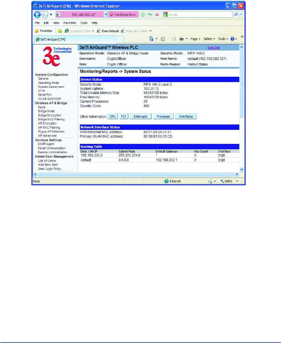
2.6.1 System Status
The Monitoring/Report - System Status screen (Figure 47) displays the status of the 3e–523 device, the
network interface, and the routing table.
Figure 47 - Monitoring/Report — System Status
There are some pop-up informational menus that give detailed information about CPU, PCI, Interrupts,
Process, and Interfaces.
2.6.2 Bridging Status
The Monitoring/Report - Bridging Status screen (Figure 48) displays the Ethernet Port STP status,
Wireless Port STP status, and Wireless Bridging information.
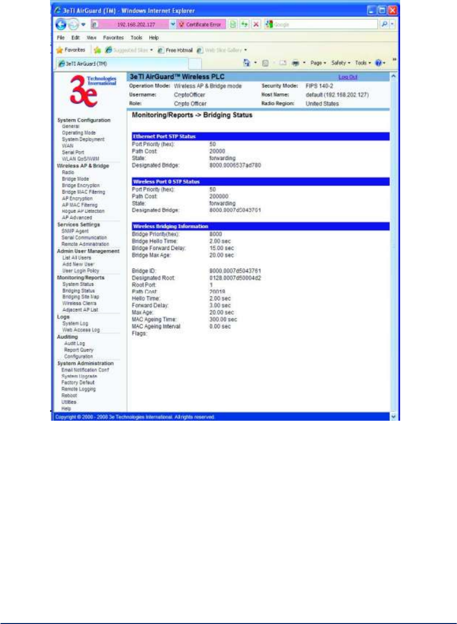
AirGuard WiMesh 3e-523 Series User’s Guide
Copyright 2015 Ultra Electronics, 3eTI
October 2015
55
29000169-005 Revision C1
Figure 48 - Monitoring/Report — Bridging Status
2.6.3 Bridge Site Map
The Bridge Site Map (Figure 49) shows the spanning tree network topology of both wired and wireless
nodes connected to the network. The root STP node is always on top and the nodes of the hierarchy are
displayed below it. Wired links are double dotted lines and wireless links are single dotted lines. This map
does not update dynamically. You must press the Update button to refresh the map.
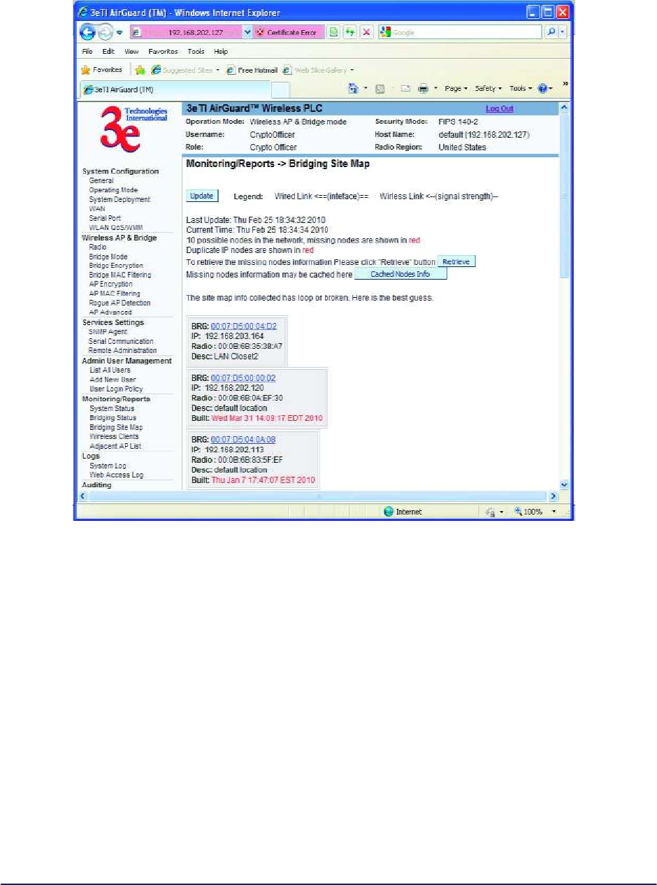
AirGuard WiMesh 3e-523 Series User’s Guide
Copyright 2015 Ultra Electronics, 3eTI
October 2015
56
29000169-005 Revision C1
Figure 49 - Monitoring/Report — Bridge Site Map
2.6.4 Wireless Clients
The Monitoring/Report - Wireless Clients screen (Figure 50) displays the MAC Address of all wireless
clients and their signal strength and transmit rate. The screen shown here emulates the FIPS 140-2 setup
and contains a column for EMCON response. This column is not displayed if the AP is in non-FIPS mode.
The EMCON feature only works with 3e-010F Crypto Client in FIPs mode.
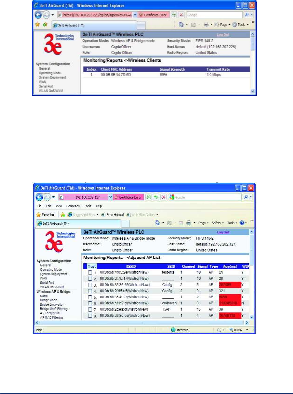
AirGuard WiMesh 3e-523 Series User’s Guide
Copyright 2015 Ultra Electronics, 3eTI
October 2015
57
29000169-005 Revision C1
Figure 50 - Monitoring/Report — Wireless Clients
2.6.5 Adjacent AP List
The Monitoring/Report - Adjacent AP List screen (Figure 51) shows all the APs on the network. If you
select the checkbox next to any AP shown, the AP will thereafter be accepted by the unit as a trusted AP.
These APs are detected by the AP's wireless card and the wireless bridge's wireless card. The list of APs
are only within the band that can be seen from a particular channel. For example, if the AP is on channel 1,
it will display APs on channels 1-3.
Figure 51 - Monitoring/Report — Adjacent AP List
2.7 Logs
There are two logs available for viewing and exporting.
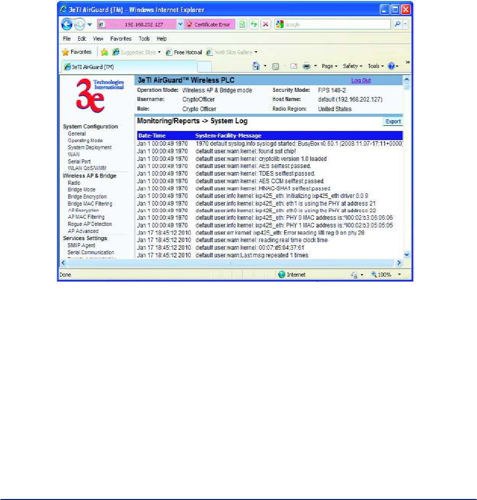
AirGuard WiMesh 3e-523 Series User’s Guide
Copyright 2015 Ultra Electronics, 3eTI
October 2015
58
29000169-005 Revision C1
2.7.1 System Log
The Logs - System Log screen (Figure 52) displays system facility messages with date and time stamp.
These are messages documenting functions performed internal to the system, based on the system’s
functionality. Generally, the Administrator would only use this information if trained as or working with a
field engineer or as information provided to technical support.
The System log continues to accumulate listings. If you wish you can export the log and save it as a file on
your PC. Click on Export.
Figure 52 - Logs — System Log
2.7.2 Web Access Log
The Web Access Log (Figure 53) displays system facility messages with date and time stamp for any
actions involving web access. For example, this log records when you set encryption mode, change
operating mode, etc., using the web browser. It establishes a running record regarding what actions were
performed and by whom.
The Web access log will continue to accumulate listings. You can set an alert point. You will be notified by
email when the alerts reach a certain threshold. If you wish you can export the log and save it as a file on
your PC. Click on Export.
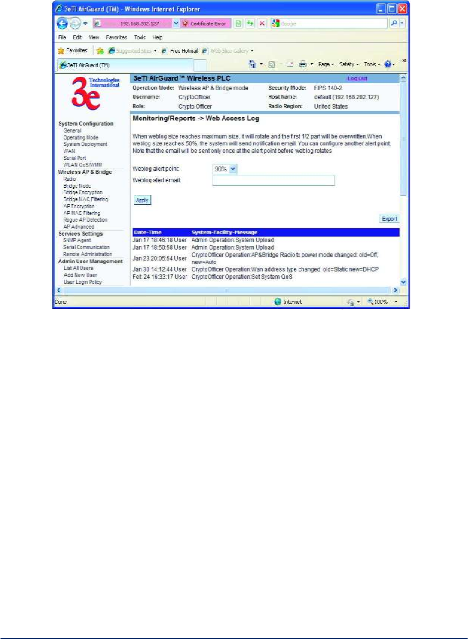
AirGuard WiMesh 3e-523 Series User’s Guide
Copyright 2015 Ultra Electronics, 3eTI
October 2015
59
29000169-005 Revision C1
Figure 53 - Web Access Log
2.8 Auditing
The unit collects audit data and provides an interface for authorized administrators to review generated
audit records. It generates records for two separate classes of events: authentication/access to the
system, and actions taken directly on the system. All audit records include the date/ time of the event, the
identity associated with the event (such as the service, computer or user), the success/failure of the event
and a definition of the event (by code or explanation).
Every start and stop of the audit service is noted in the audit record. For audit events resulting from actions
of identified users, the unit associates each auditable event with the identity of the user that caused the
event. The unit includes or excludes auditable events from the set of audited events based on object
identity, user identity, subject identity, host identity, and event type.
The Auditing screens contain auditing functions for the system. The screens and functions are detailed in
the following subsections.
2.8.1 Audit Log
The Auditing—Audit Log screen (Figure 54) provides a listing of all the audit records.
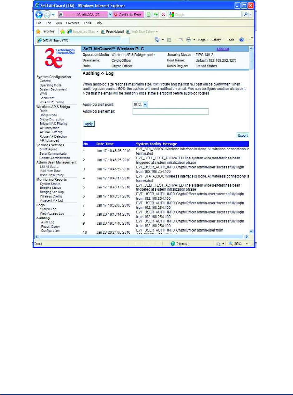
AirGuard WiMesh 3e-523 Series User’s Guide
Copyright 2015 Ultra Electronics, 3eTI
October 2015
60
29000169-005 Revision C1
Figure 54 - Auditing — Audit Log
2.8.2 Report Query
The Auditing—Report Query screen (Figure 55) allows you to query on report based on start time, end
time, MAC address, or unique record IDs.
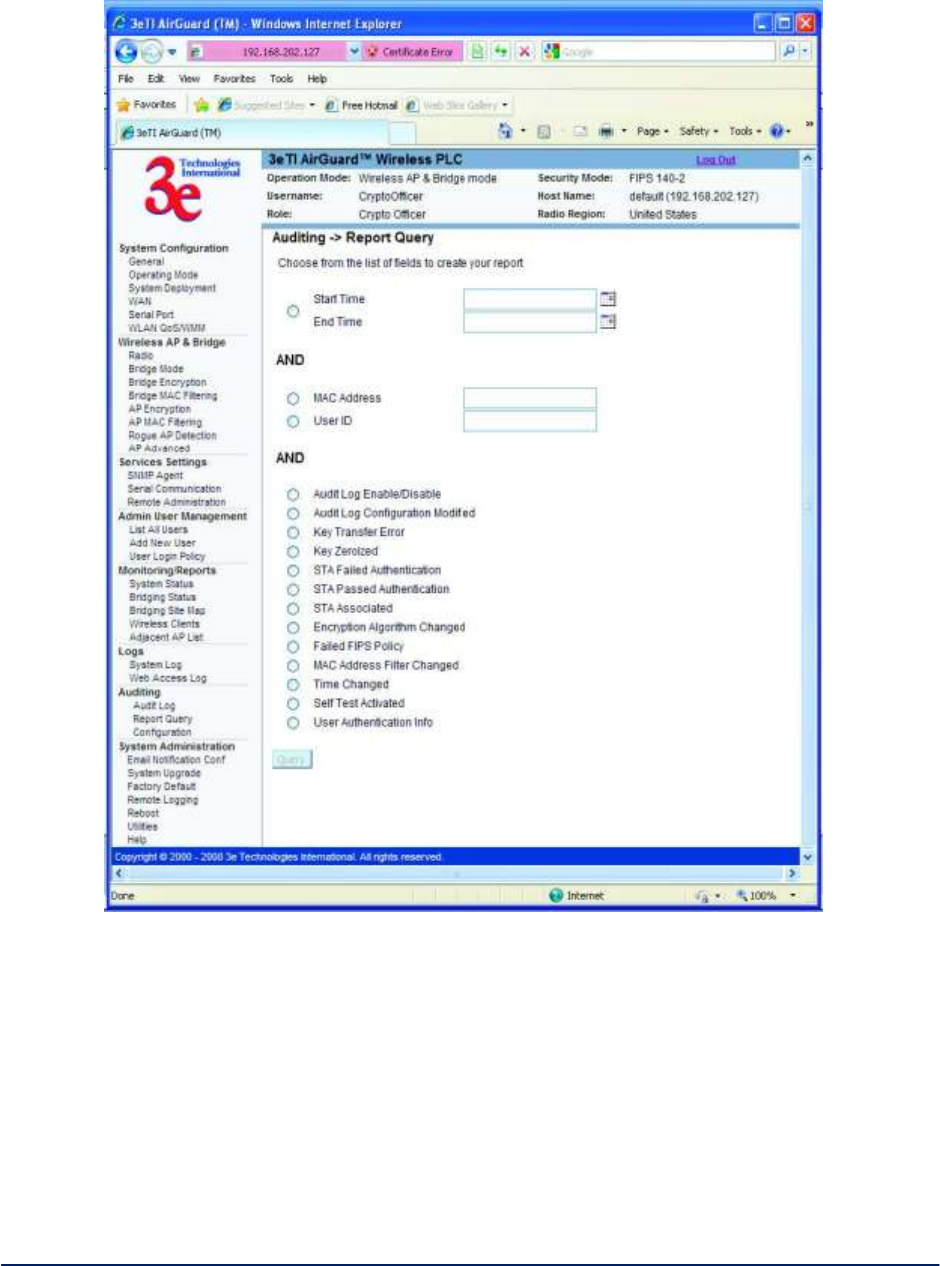
AirGuard WiMesh 3e-523 Series User’s Guide
Copyright 2015 Ultra Electronics, 3eTI
October 2015
61
29000169-005 Revision C1
Figure 55 - Auditing — Report Query
2.8.3 Configuration
The Auditing—Configuration screen is used to configure the auditing settings. You can enable and
disable the auditing function on this screen. You can select which audit event types you wish to log.Figure
56 below shows the screen and Table 7 lists event types and descriptions.
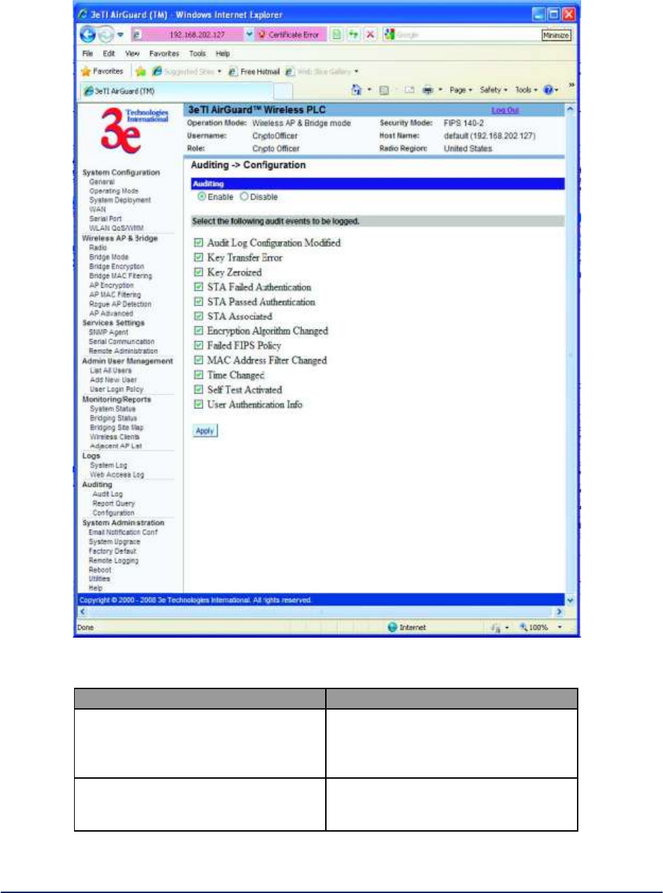
AirGuard WiMesh 3e-523 Series User’s Guide
Copyright 2015 Ultra Electronics, 3eTI
October 2015
62
29000169-005 Revision C1
Figure 56 - Auditing — Configuration
Table 7 - Auditing — Configuration Event Type and Description
Event Type
Description
Audit Log Configuration Modified
Any modification to the audit log
configuration (enable/disable,
recorded event types, etc) will trigger
the creation of an audit record.
Key Transfer Error
Any error detected during the
dynamic key exchange, either to the
station or the authentication server.

AirGuard WiMesh 3e-523 Series User’s Guide
Copyright 2015 Ultra Electronics, 3eTI
October 2015
63
29000169-005 Revision C1
Key Zeroized
The keys are zeroized including:
1. Transitioning from static key to
DKE (and vice versa)
2. Transitioning to bypass mode
Individual log messages appear from
the application and driver since keys
are held in both locations.
STA Failed Authentication
A station's authentication request is
dropped because it doesn't match the
MAC address filter.
STA Associated
A station successfully associates to
the AP.
Encryption Algorithm Changed
The encryption algorithm is changed,
including bypass mode.
Failed FIPS Policy
All HMAC/AES decrypt errors that
can be detected.
MAC Filter Changed
The MAC address filter is changed
including adding/deleting,
enable/disable, and changing filter
type.
Time Changed
Whenever the time is changed via the
GUI or at bootup if the time is within
two minutes of 11/30/1999, 0hr, 0min.
Self Test Activated
The self-test function is run.
2.9 System Administration
There are six options under System Administration:
Email Notification Configuration
System Upgrade
Firmware Upgrade
Local Configuration Upgrade
Remote Configuration Upgrade
Factory Default
Remote Logging
Reboot
Utilities
Each screen is described in detail in the following subsections.
2.9.1 E-mail Notification Configuration
All system notification emails need to be set up using the System Administration - Email Notification
Configuration screen (Figure 57). Your email server must support SMTP protocol. If you email server
does not require authentication to send email then leave the username/password fields blank. If your email
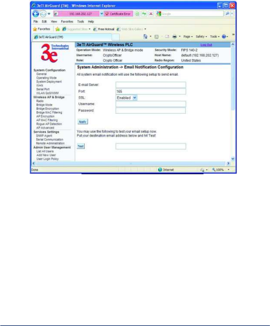
AirGuard WiMesh 3e-523 Series User’s Guide
Copyright 2015 Ultra Electronics, 3eTI
October 2015
64
29000169-005 Revision C1
server does not support SSL (Secure Socket Layer) then disable SSL on the 3e–523. You may also test
your email setup using the test feature on this screen.
NOTE: Check your connection to the mail server. Emails sent from the 3e–523 may be queued for a short
period if the connection fails temporarily, but it will give up if the connection continues to fail.
Figure 57 - System Administration — Email Notification Configuration
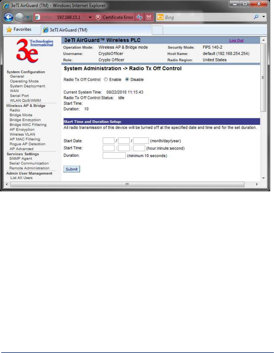
AirGuard WiMesh 3e-523 Series User’s Guide
Copyright 2015 Ultra Electronics, 3eTI
October 2015
65
29000169-005 Revision C1
2.9.2 Radio Tx Off Control
Figure 58 - System Administration — Radio Tx Off Control
2.9.3 System Upgrade
The System Administration - System Upgrade screen (Figure 59) gives you the ability to upload updates
to the 3e–523 device’s firmware as they become available. When a new upgrade file becomes available,
you can do a firmware upgrade from the Firmware Upgrade window.
There is also a configuration file transfer option which allows the system configuration file from one AP to
be transferred to another AP, in order to minimize the administration of the APs. Only configuration
parameters that can be shared between APs are downloaded in the configuration file. WAN IP address
and hostname are not transferred in the configuration file.
Only the Crypto Officer role can access this function.
Firmware Upgrade - On the System Administration - System Upgrade screen (Figure 59), the
Firmware Upgrade tab is the default view.
Click browse and select the firmware file to be uploaded. Click on the Upload Firmware button.
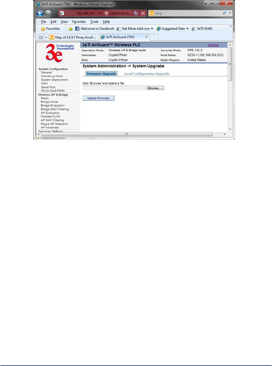
AirGuard WiMesh 3e-523 Series User’s Guide
Copyright 2015 Ultra Electronics, 3eTI
October 2015
66
29000169-005 Revision C1
Figure 59 - System Administration — Firmware Upgrade
Local Configuration Upgrade - On the System Administration - System Upgrade screen (
Figure 60Figure 60), click on the Local Configuration Upgrade tab to upload and download configuration
files to other 3e–523 devices connected to the network.
To upload a configuration file, select the file using the browse button and enter the passphrase for that file.
The passphrase protects the file from unauthorized users. It prevents unauthorized users from applying
the system configuration file to an unauthorized device to gain access to the network. Before downloading
the system configuration file to a local computer, the user must enter a passphrase to protect the file.
Before the system configuration file can be uploaded onto another 3e–523 device, the passphrase must be
entered on the remote 3e–523 device.
Notes:
1. When downloading configuration files, keys are NOT downloaded.
2. When uploading configuration file to a device, if the device currently is configured to the same
security options as those in the uploaded file, the keys are reused. Otherwise, the keys are
zeroized and marked “key not set” from web GUI.
e.g. Current device has 802.11i-PMK option on AP security. The configured to be uploaded will
use 802.11i-PMK for AP security. Existing 256bit PMK is reused. Otherwise, AP security is
marked “key not set”.
3. In VLAN scenario, VLAN ID (NOT the SSID) is the index to find matching security option.
E.g. Current device has 3 VLAN configured as follows.
a. VLAN ID = 1, SSID=area-1, security=802.11i pmk
b. VLAN ID = 2, SSID=area-2, security=802.11i-dot1x
c. VLAN ID = 3, SSID=area-3, security=static AES
The configuration file to be uploaded has 4 VLAN configured as follows.
a. VLAN ID = 1, SSID=test-1, security=802.11i pmk
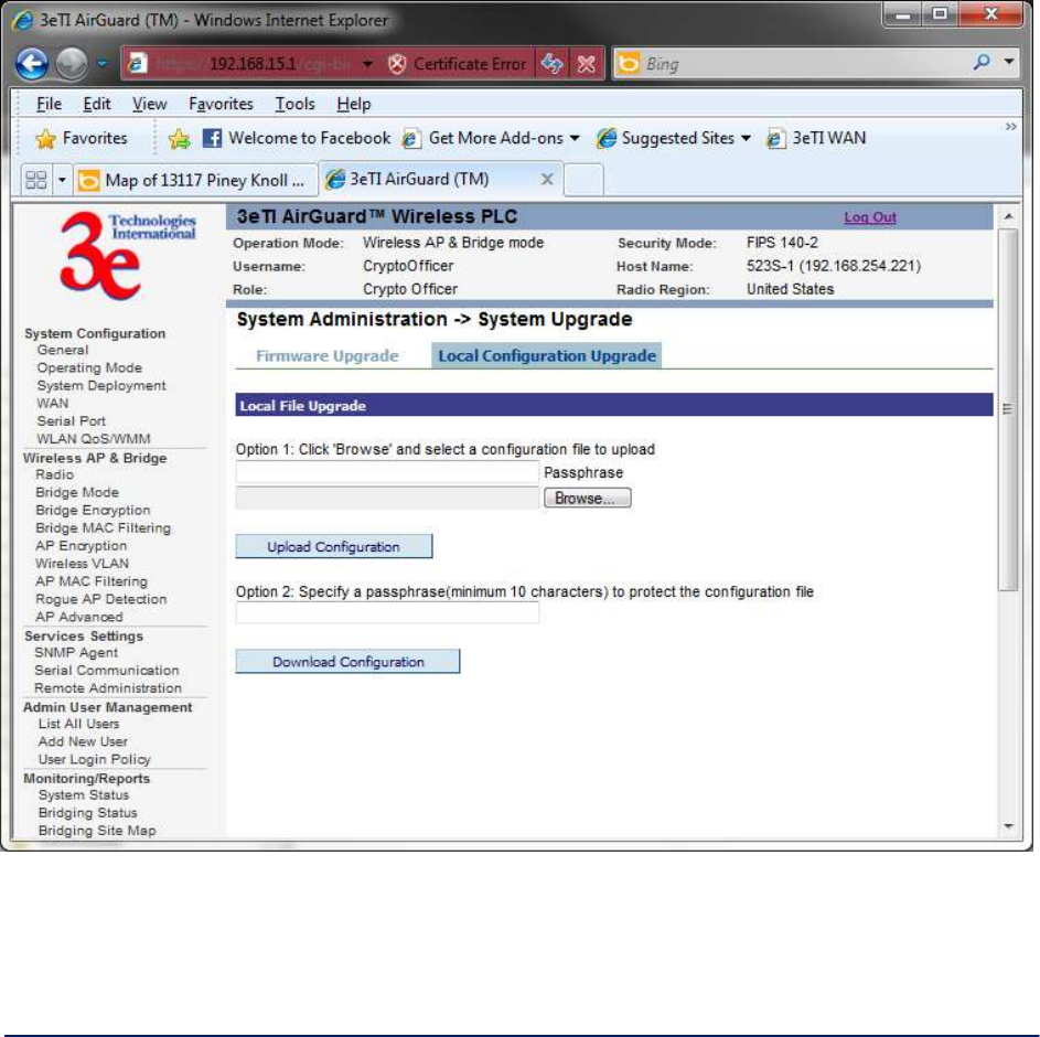
AirGuard WiMesh 3e-523 Series User’s Guide
Copyright 2015 Ultra Electronics, 3eTI
October 2015
67
29000169-005 Revision C1
b. VLAN ID = 2, SSID=area-1, security=802.11i-dot1x
c. VLAN ID = 3, SSID=area-2, security=802.11i pmk
d. VLAN ID = 4, SSID=area-3, security=static AES
The device will have 4 VLANs configured as follows
a. VLAN ID = 1, SSID=test-1, security=802.11i pmk (key set)
b. VLAN ID = 2, SSID=area-1, security=802.11i-dot1x (key set)
c. VLAN ID = 3, SSID=area-2, security=802.11i pmk (key not set)
d. VLAN ID = 4, SSID=area-3, security=static AES (key not set)
Figure 60 -System Administration — Local Configuration Upgrade
2.9.4 Factory Default
The System Administration - Factory Default screen (Figure 61) is used to reset the 3e–523 to its
factory settings.
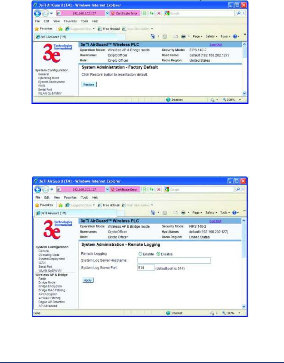
AirGuard WiMesh 3e-523 Series User’s Guide
Copyright 2015 Ultra Electronics, 3eTI
October 2015
68
29000169-005 Revision C1
The "Restore" button is a fallback troubleshooting function that should only be used to reset to original
settings. Only the Crypto Officer role has access to the Restore button.
Figure 61 - System Administration - Factory Default
2.9.5 Remote Logging
The System Administration —Remote Logging screen (Figure 62) allows you to forward the syslog data
from each machine to a central remote logging server. In the 3e–523, this function uses the syslogd
daemon. If you enable Remote Logging, input a System Log Server IP Address and System Log Server
Port. Click Apply to accept these values.
Figure 62 - System Administration - Remote Logging
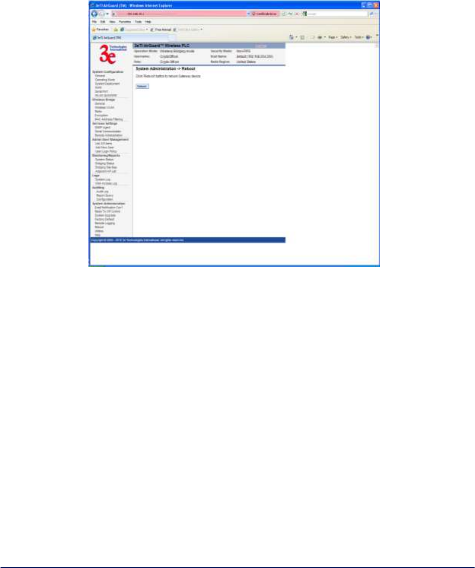
AirGuard WiMesh 3e-523 Series User’s Guide
Copyright 2015 Ultra Electronics, 3eTI
October 2015
69
29000169-005 Revision C1
2.9.6 Reboot
The System Administration - Reboot screen (Figure 63) allows you to reboot the 3e–523 without
changing any preset functionality. Both Crypto Officer and Administrator functions have access to this
function.
Figure 63 - System Administration - Reboot
2.9.7 On Demand Self-test
Self-tests are run to verify the correctness of cryptographic related functions. Two cryptographic libraries
support these tests:
OpenSSL crypto library – free software from the OpenSSL project. This library is used by user space
applications.
Kernel crypto library – This library is used by kernel space applications. It can be supported by hardware (if
available) or software. All 3e525A-3 platforms will support the hardware kernel library.
The following tests are available using the OpenSSL library:
Advanced Encryption Standard (ECB mode)
Triple DES
Secure Hash Algorithm 1
Random Number Generator
Hashed Message Authentication Code
RSA Algorithm
Firmware Integrity Check
Bootloader Integrity Check
The following tests are available using the kernel libraries:
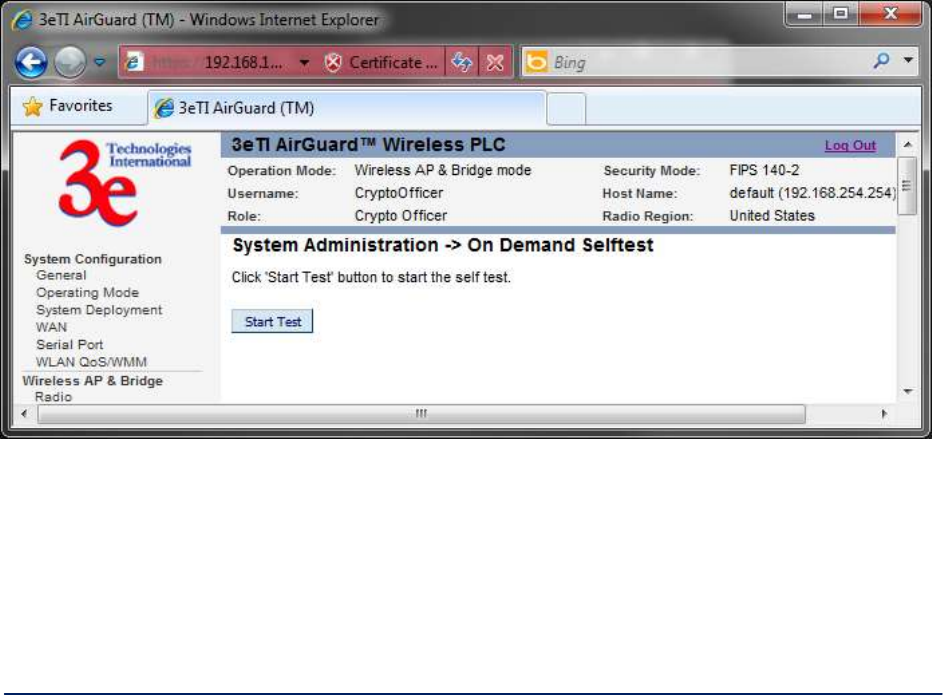
AirGuard WiMesh 3e-523 Series User’s Guide
Copyright 2015 Ultra Electronics, 3eTI
October 2015
70
29000169-005 Revision C1
Advanced Encryption Standard (ECB mode)
Advanced Encryption Standard (CCM mode)
Secure Hash Algorithm 1
Hashed Message Authentication Code
Key Error Detection – checks for corruption of keys stored in flash
The following tests do not rely on crypto libraries:
Key Error Detection – checks for corruption of keys stored in flash
Test results are written to the system log. Test failures are also written to the console. The platform should
not pass secure data while self tests are executing so network interfaces are disabled during self tests.
The platform is halted if any self test fails.
These tests are run during power up, on demand or periodically. All of the above tests are executed
automatically when the platform is powered up. Links to initiate on-demand or periodic selftests are
available on the platform’s web page under “System Administration” if the user is logged in as a crypto
officer.
On-demand Self-test - Selecting the “On Demand Self-test” link (Figure 64) and clicking on “Start Test”
executes each self-test except the firmware and bootloader integrity checks. A web page will be displayed
indicating if the tests passed or failed.
Figure 64 - System Administration – On Demand Self-test
2.9.8 Periodic Self-test
Selecting the “Periodic Self-test” link (Figure 65 allows the user to enable/disable periodic tests. A test
iteration executes each selftest except the firmware and bootloader integrity checks. The “Periodic Test
Interval” is the time between test iterations.
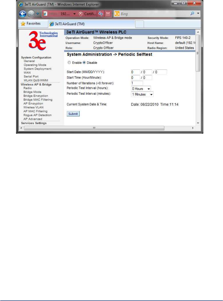
AirGuard WiMesh 3e-523 Series User’s Guide
Copyright 2015 Ultra Electronics, 3eTI
October 2015
71
29000169-005 Revision C1
Figure 65 - System Administration – Periodic Self-test
2.9.9 Utilities
The System Administration - Utilities screen (Figure 66) gives you ready access to two useful utilities:
Ping and Traceroute. Simply enter the IP Address or hostname you wish to ping or traceroute and click
either the Ping or Traceroute button, as appropriate.
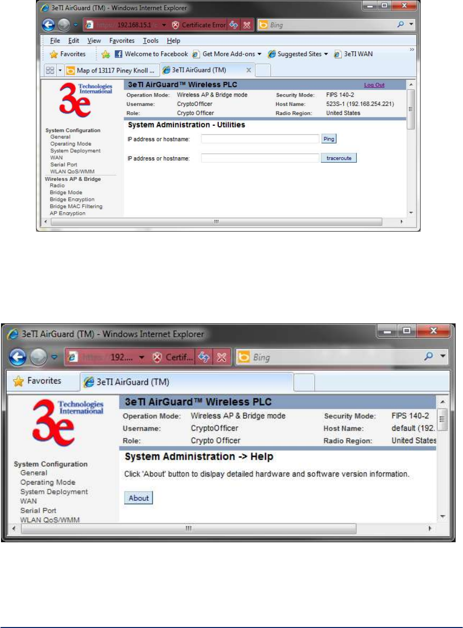
AirGuard WiMesh 3e-523 Series User’s Guide
Copyright 2015 Ultra Electronics, 3eTI
October 2015
72
29000169-005 Revision C1
Figure 66 - System Administration - Utilities
2.9.10 Help
The System Administration - Help screen (Figure 67) displays detailed hardware and software version
information.
Figure 67 - System Administration - Help
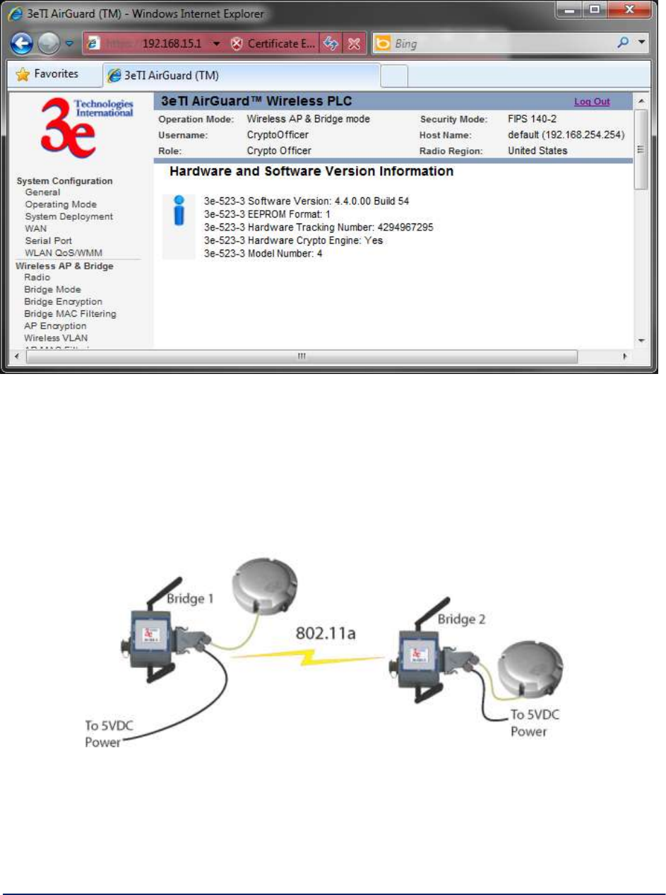
AirGuard WiMesh 3e-523 Series User’s Guide
Copyright 2015 Ultra Electronics, 3eTI
October 2015
73
29000169-005 Revision C1
Figure 68 - System Administration – Help ResultsA
2.10 Operational Configurations
Setting Up Bridging Type Point-to-Point Bridge Configuration
A point-to-point link (Figure 69) is a direct connection between two, and only two, locations or nodes.
Figure 69 - Point-to-Point Link
For the two bridges that are to be linked to communicate properly, they must be set up with compatible
commands in the setup screens.

AirGuard WiMesh 3e-523 Series User’s Guide
Copyright 2015 Ultra Electronics, 3eTI
October 2015
74
29000169-005 Revision C1
For instance, the bridges must have the same channel number. Because there is a separate
WLAN card for bridging, there can be a separate WLAN on the AP WLAN card with no loss
efficiency, as long as you set the channel numbers so there's no conflict or noise with the channel
assigned to the bridge. Spanning Tree Protocol may be set to Enable, if there is any possibility of a
bridging loop, or to Disable (which is more efficient) if there's no possibility of a bridging loop. Each
bridge must contain the other's BSSID. (The BSSID of each is equivalent to the MAC address
contained on the Wireless AP & Bridge — Radio setup page. Enter only hexadecimal numbers,
no colons. Data entry is not case sensitive.) Finally, the wireless bridging encryption must be set to
the appropriate type and key length and must be identical on each bridge.
Table 8 and Table 9 below lists sample settings for manual bridging and auto bridging modes.
Table 8 - Point-to-Point Bridging Setup Guide — Manual Mode
Direction
Bridge 1
Bridge 2
Wireless Bridge — Bridging Mode (Manual Bridging Mode)
Bridging Mode
Manual bridging selected
Manual bridging selected
Signal Strength LED MAC
Not Assigned (select from
drop-down list)
Not Assigned (select from
drop-down list)
Spanning Tree Protocol
(STP)
Enable (or Disable if no
bridging
loop possible)
Enable (or Disable if no
bridging
loop possible)
Wireless Bridge — Radio
Wireless Mode
802.11a
802.11a
Tx Rate
AUTO
AUTO
Channel No.
Must be the same as
Bridge 2
Must be the same as
Bridge 1
Tx Power Mode
Auto
Auto
Propagation Distance
< 5 Miles
< 5 Miles
RTS Threshold
2346
2346
Beacon Interval
1000
1000
BSSID
Add Bridge 2 MAC
Add Bridge 1 MAC
Wireless Bridge — Encryption
Bridging encryption
options
Select appropriate key
type/length and value.
Must be the
same key as Bridge 2.
Select appropriate key
type/length and value.
Must be the
same key as Bridge 1.
Table 9 - Point-to-Point Bridging Setup Guide — Auto Mode
Direction
Bridge 1
Bridge 2
Wireless Bridge — Bridging Mode (Auto Bridging Mode)
Bridging Mode
Auto bridging selected
Auto bridging selected
SSID
Must be the same as
Bridge 2
Must be the same as
Bridge 1
Max Auto Bridges
32 (range 1-32)
32 (range 1-32)
Bridge Priority
32768 (range 1-65535)
32768 (range 1-65535)
RSSI Window Size
5
5
Signal Strength Threshold
9%
9%
Link Sensitivity
15%
15%

AirGuard WiMesh 3e-523 Series User’s Guide
Copyright 2015 Ultra Electronics, 3eTI
October 2015
75
29000169-005 Revision C1
Broadcast SSID
Disable
Disable
Signal Strength MAC
Enter from list at the
bottom of the screen
Enter from list at the
bottom of the screen
Wireless Bridge — Radio
Wireless Mode
802.11a
802.11a
Tx Rate
AUTO
AUTO
Channel No
Must be the same as
Bridge 2
Must be the same as
Bridge 1
Tx Power Mode
Auto
Auto
Propagation Distance
< 5 Miles
< 5 Miles
RTS Threshold
2346
2346
Beacon Interval
1000
1000
Wireless Bridge — Encryption
Bridging encryption
options
Select appropriate key
type/length and value.
Must be same as Bridge 2.
Select appropriate key
type/length and value.
Must be same as Bridge 1.
The following sequence walks you through the setup of bridge 1. Bridge 2 would duplicate this procedure,
with the BSSID of bridge 2 being the MAC address of bridge 1 and vice versa.
Navigate to the Wireless Bridge — Radio screen (Figure 70).
In the first section you will see the MAC Address of the bridging card. This is used as the BSSID on other
3e–523–3s that will be communicating with this one.
Select the Wireless Mode to be used for bridging. Set the Tx Rate to a fixed transmit rate or select AUTO
if you want the card to attempt to select the optimal rate for the channel If the Tx rate is set to a fixed rate,
then the card will only transmit at that rate.
Next select the Channel Number. The Channel Number must be set to the same frequency in order for
each bridge to communicate. TX Pwr Mode can be left on Auto unless the power needs to be regulated.
Select the Propagation Distance which is based on the distance between a bridge and the furthest bridge
that is connected to it.
Set the RTS Threshold which is the number of bytes used for the RTS/CTS handshake boundary. When
a packet size is greater than the RTS threshold, the RTS/CTS handshaking is performed.
Click Apply to accept your changes but stay on this screen.
Add the BSSID of the remote bridge. The BSSID corresponds to that bridge’s MAC address. In entering
the BSSID, enter only hexadecimal numbers, no colons. Data entry is not case sensitive. You may also
enter a note that defines the location of the remote bridge. Then click Add to accept. The remote bridge’s
BSSID will now appear at the bottom of the Wireless Bridge - Bridging Mode screen.
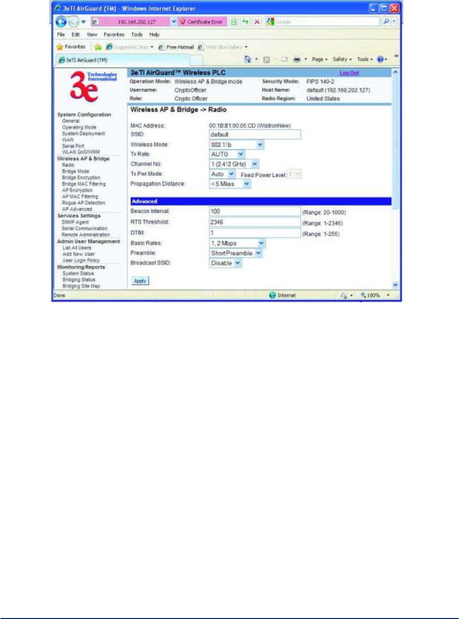
AirGuard WiMesh 3e-523 Series User’s Guide
Copyright 2015 Ultra Electronics, 3eTI
October 2015
76
29000169-005 Revision C1
Figure 70 - Wireless Bridge - Radio
Next go to the Wireless Bridge - Bridging Mode screen (Figure 71). Select either manual or auto
bridging. If you choose Manual Bridging then you will have to set Spanning Tree Protocol to Enable
unless you are sure that there is no chance of a loop. You can also assign a Signal Strength LED MAC.
Signal strength LED MAC allows you to set the number of one of the Remote APs which will be listed at
the bottom of the screen once the system is operational as the guiding port that you wish to have display in
the WLANSS LED on the front of the 3e–523–3 as a signal. If you don’t wish to display any connection
signal, simply leave this set at Not Assigned. From this screen you can also choose to delete a remote
AP's MAC address.
Click Apply to accept your changes.
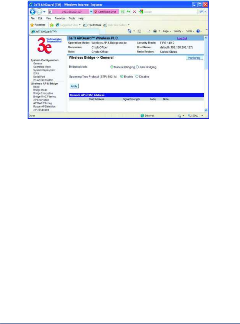
AirGuard WiMesh 3e-523 Series User’s Guide
Copyright 2015 Ultra Electronics, 3eTI
October 2015
77
29000169-005 Revision C1
Figure 71 - Wireless Bridge - Bridging Mode
If you choose Auto Bridging mode (Figure 72), then you will need to enter the following information:
Enter the SSID. This can be any set of letters and numbers assigned by the network administrator. This
nomenclature has to be set on the wireless bridge and each wireless device in order for them to
communicate.
Enter a number from 1 to 32 for the Max Auto Bridges. Next enter the Bridge Priority (range from
1-65535). This determines the root (leaf) STP node. The lowest bridge priority in the network will become
the STP root.
Select the Signal Strength Threshold.
Either enable or disable the Broadcast SSID. When disabled, the bridge hides the SSID in outgoing
beacon frames and stations cannot obtain the SSID through passive scanning. Also, when it is disabled,
the bridge doesn’t send probe responses to probe requests with unspecified SSIDs.
Finally enter the Signal Strength MAC. The signal strength of this wireless bridge will be indicated on the
Signal Strength LED located on the front of the case.
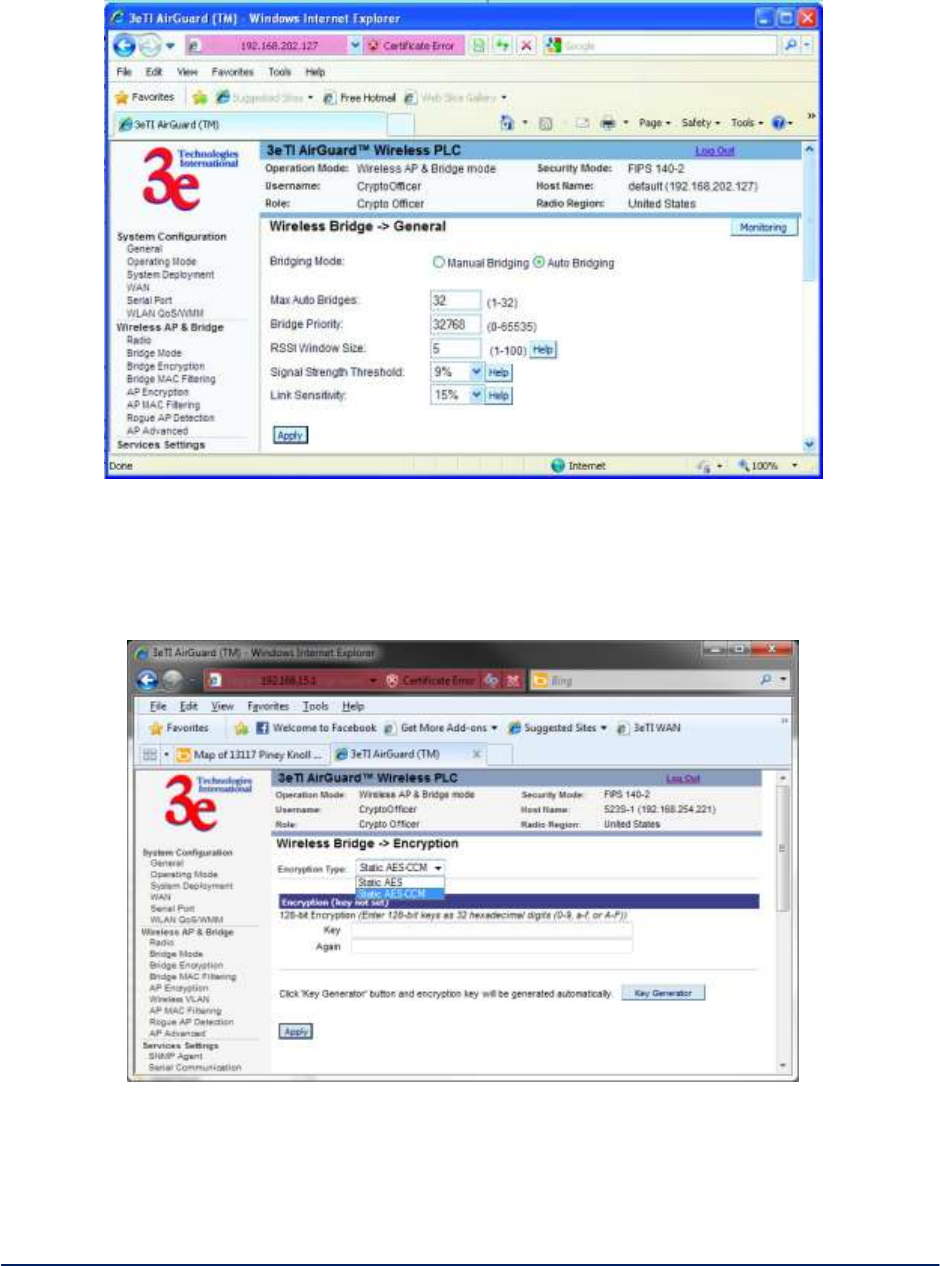
AirGuard WiMesh 3e-523 Series User’s Guide
Copyright 2015 Ultra Electronics, 3eTI
October 2015
78
29000169-005 Revision C1
Figure 72 - Wireless Bridge - Auto Bridging Mode
Next, navigate to the Wireless Bridge — Encryption screen (Figure 73). Select the appropriate key type
and length and the key value. The encryption key value and type for Bridge 1 must be the same as for
Bridge 2. For wireless bridging, only AES and 3DES are available for encryption.
Figure 73 - Wireless Bridge - Encryption
Configure the second of your two point-to-point bridges following the instructions given for Bridge 1 above.
Point-to-Multipoint Bridge Configuration
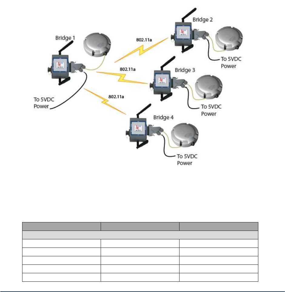
AirGuard WiMesh 3e-523 Series User’s Guide
Copyright 2015 Ultra Electronics, 3eTI
October 2015
79
29000169-005 Revision C1
A point-to-multipoint configuration (Figure 74) allows you to set up three or more 3e–523 units in bridging
mode and accomplish bridging between 3 or more locations wirelessly.
For the three bridges that are to be linked to communicate properly, they have to be set up with compatible
commands in their setup screens.
For instance, all bridges must have the same channel number. Spanning Tree Protocol will usually be set
to Enable. If configured as in the diagram following, Bridge 1 must contain all of the others' BSSIDs, while
Bridge 2 ~ n must only contain Bridge 1's BSSID. (The BSSID of each is equivalent to the MAC address
found on the Wireless Bridge - Radio page. Enter only hexadecimal numbers. Data entry is not case
sensitive.) Finally, the wireless bridging encryption of each must be set to the appropriate type and key
length and must be the same on all.
Figure 74 - Point-to-Multipoint Bridge Configuration
Follow the steps of the procedure outlined in the point-to-point bridge section. Table 10 and Table 11
below describe the basic attributes.
Table 10 - Point-to-Multipoint Bridging Setup Guide - Manual Mode
Direction
Bridge 1
Bridge 2 ~ n
Wireless Bridge — Radio
Wireless Mode
802.11a
802.11a
Tx Rate
AUTO
AUTO
Channel No.
Same as Bridge 2~n
Same as Bridge 1
Tx Power Mode
Auto
Auto
Propagation Distance
< 5 Miles
< 5 Miles

AirGuard WiMesh 3e-523 Series User’s Guide
Copyright 2015 Ultra Electronics, 3eTI
October 2015
80
29000169-005 Revision C1
RTS Threshold
2346
2346
Beacon Interval
1000
1000
BSSID
Add Bridge 2~n MAC
Add Bridge 1 MAC
Wireless Bridge — Bridging Mode (Manual Bridging Mode)
Bridging Mode
Manual bridging selected
Manual bridging selected
Signal Strength LED MAC
Not Assigned (select from
drop-down list)
Not Assigned (select from
drop-down list)
Spanning Tree Protocol
Enable (or Disable if no
bridging loop possible)
Enable (or Disable if no
bridging loop possible)
Wireless Bridge — Encryption
Bridging encryption
options
Select appropriate key
type/length and value.
Must be the same key as
Bridge 2~n.
Select appropriate key
type/length and value.
Must be the same key as
Bridge 1.
Table 11 - Point-to-Multipoint Bridging Setup Guide — Auto Mode
Direction
Bridge 1
Bridge 2
Wireless Bridge — Radio
Wirelss Mode
802.11a
802.11a
Tx Rate
AUTO
AUTO
Channel No.
Same as Bridge 2~n
Same as Bridge 1
Tx Power Mode
Auto
Auto
Propagation Distance
< 5 Miles
< 5 Miles
RTS Threshold
2346
2346
Beacon Interval
1000
1000
BSSID
Add Bridge 2~n MAC
Add Bridge 1 MAC
Wireless Bridge — Bridging Mode (Auto Bridging Mode)
Bridging Mode
Manual bridging selected
Auto bridging selected
SSID
Must be the same as
Bridge 2~n
Must be the same as
Bridge 2
Max Auto Bridges
32 (range 1-32)
32 (range 1-32)
Bridge Priority
32768 (range 1-65535)
32768 (range 1-65535)
RSSI Window Size
5
5
Signal Strength Threshold
9%
9%
Link Sensitivity
15%
15%
Signal Strength MAC
Enter from list at the
bottom of the screen
Enter from list at the
bottom of the screen
Wireless Bridge — Encryption
Bridging encryption
options
Select appropriate key
type/length and value.
Must be same as Bridge 2.
Select appropriate key
type/length and value.
Must be same as Bridge 1.
The above recommended setup requires only Bridge 1 to be set in point-to-multipoint mode. It is possible
to set all bridges in point-tomultipoint mode, in which case , each bridge would have to contain the BSSID
for each of the other bridges and Spanning Tree Protocol must be Enabled.
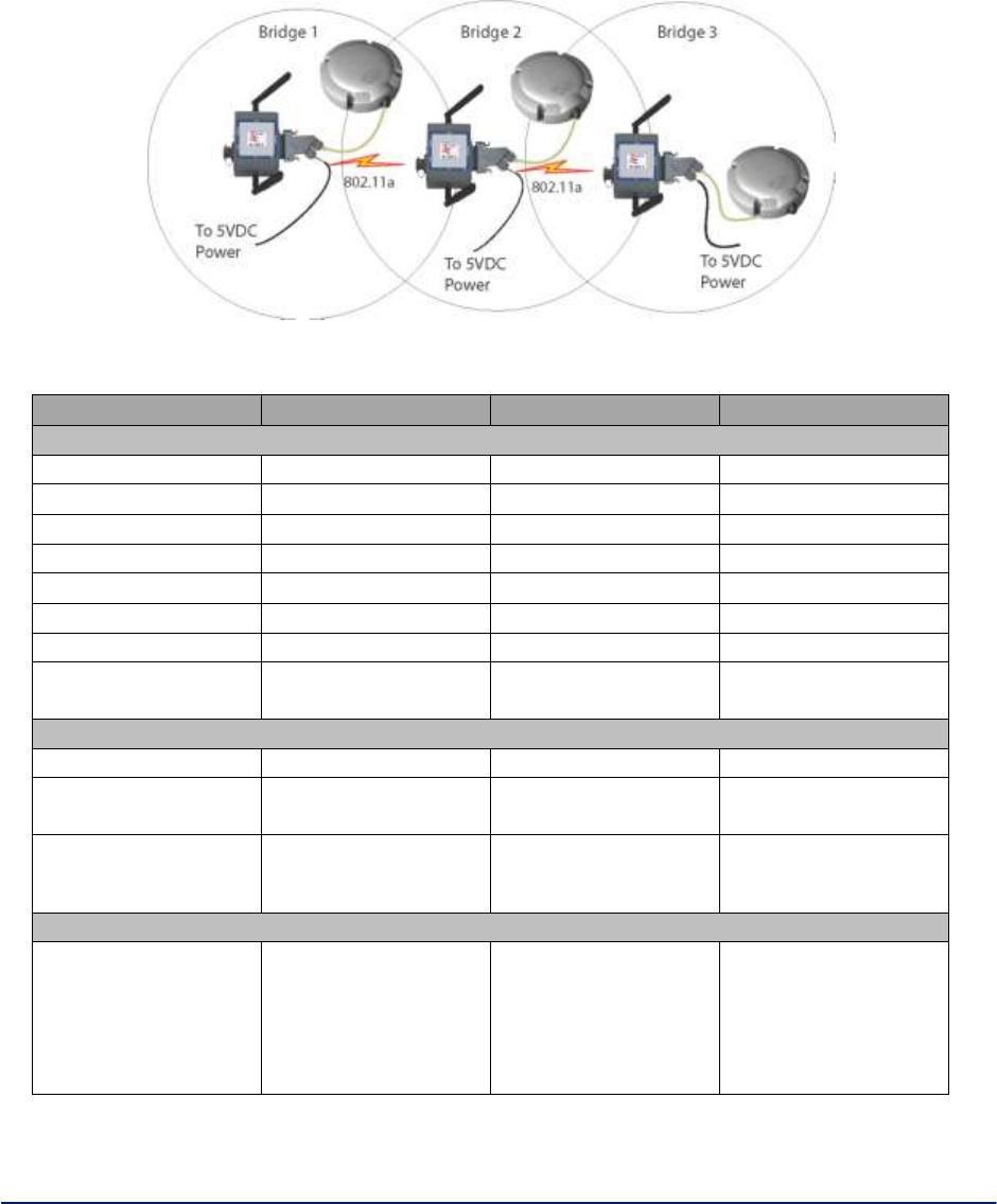
AirGuard WiMesh 3e-523 Series User’s Guide
Copyright 2015 Ultra Electronics, 3eTI
October 2015
81
29000169-005 Revision C1
Repeater Bridge Configuration
A repeater setup can be used to extend the wireless signal from one bridge connected to an Ethernet LAN
wirelessly so that another bridge can control a wireless LAN at a distance (Figure 75). Table 12
describes the basic attributes.
Figure 75 - Repeater Bridge Configuration
Table 12 - Repeater Bridging Setup Guide — Manual Mode
Direction
Bridge 1
Bridge 2
Bridge 3
Wireless Bridge — Radio
Wireless Mode
802.11a
802.11a
802.11a
Tx Rate
AUTO
AUTO
AUTO
Channel No.
Same as Bridge 2
Same as Bridge 1
Same as Bridge 1
Tx Power Mode
Auto
Auto
Auto
Propagation Distance
< 5 Miles
< 5 Miles
< 5 Miles
RTS Threshold
2346
2346
2346
Beacon Interval
1000
1000
1000
BSSID
Add Bridge 2's MAC
Add Bridge 1's and
Bridge 3's MAC
Add Bridge 2's MAC
Wireless Bridge — Bridging Mode (Manual Bridging Mode)
Bridging Mode
Manual
Manual
Manual
Signal Strength
LED MAC
Not Assigned (select
from drop-down list)
Not Assigned (select
from drop-down list)
Not Assigned (select
from drop-down list)
Spanning Tree
Protocol
Enable (or Disable if
no bridging loop
possible)
Enable (or Disable if
no bridging loop
possible)
Enable (or Disable if
no bridging loop
possible)
Wireless Bridge — Encryption
Wireless
Configuration
– Bridging Encryption
Select appropriate
key type/length and
enter key value. Must
be the same as that
on the other two
Bridges
Select appropriate
key type/length and
enter key value. Must
be the same as that
on the other two
Bridges
Select appropriate
key type/length and
enter key value. Must
be the same as that
on the other two
Bridges

AirGuard WiMesh 3e-523 Series User’s Guide
Copyright 2015 Ultra Electronics, 3eTI
October 2015
82
29000169-005 Revision C1
3. WiMesh End Points 3e-523A and 3e-523E-900 Hardware
Installation
3.1 3e-523A Hardware Installation
Preparation for Use
This section deals with installation of the 3e–523A unit. The unit requires physical mounting and
installation on the site, following a prescribed placement design to ensure optimum operation.
The package includes the following items:
The Device
Documentation as PDF files (on CD-ROM)
Registration and Warranty cards
The device has the following available accessories:
Outdoor Accessory Kit (3e-523-OAK)
Indoor Accessory Kit (3e-523-IAK)
DIN Rail Accessory Kit (3e-523-DINR-IN)
The device can be mounted outdoors on a high post to achieve the best bridge result. If mounted outdoors,
the outdoor accessory kit must be used to prevent lightning damage.
IMPORTANT NOTE:
To comply with FCC RF exposure compliance requirements, the antennas
used with the 3e-523A must be installed with a minimum separation distance of
21.5 cm from all persons, and must not be co-located or operated in conjunction
with any other antenna or transmitter. Installation should be accomplished using
the authorized cables and/or connectors provided with the device or available from
the manufacturer/distributor for use with this device. Changes or modifications not
expressly approved by the manufacturer or party responsible for this FCC
compliance could void the user’s authority to operate the equipment.
Installation Instructions
This manual deals only and specifically with a single device as a unit. The purpose of this chapter is to
describe the device and its identifiable parts so that the user is sufficiently familiar to interact with the
physical unit. Preliminary setup information provided below is intended for information and instruction of
the wireless LAN system administration personnel.
It is intended that the user not open the unit. Any maintenance required is limited to the external enclosure
surface, cable connections, and to the management software (as described in Chapter 2) only.
Minimum System and Component Requirements
To complete the configuration, you should have at least the following components:
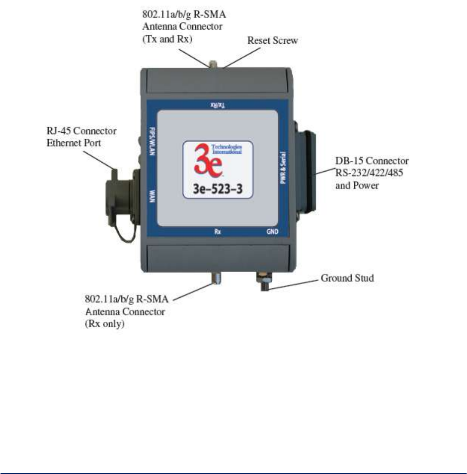
AirGuard WiMesh 3e-523 Series User’s Guide
Copyright 2015 Ultra Electronics, 3eTI
October 2015
83
29000169-005 Revision C1
PCs with one of the following operating systems installed: Windows NT 4.0, Windows 2000 or
Windows XP
Access to at least one laptop or PC with an Ethernet card and cable that can be used to complete
the initial configuration of the unit.
A Web browser program (such as Microsoft Internet Explorer 6.0 or later, or Netscape 6.3 or later)
installed on the PC or laptop you will be using to configure the Access Point.
TCP/IP Protocol (usually comes installed on any Windows PC.)
3.1.1 Connectors and Cabling
Figure 76 shows the external connectors on the device
Figure 76 - device external connectors
The RJ-45 Ethernet port is a standard 10/100 Ethernet connection. The DB-15 connector is a serial
RS232/422/485 I/O port that is also the power interface. The power source should be +5V DC @ 3 amps.
The top antenna is an 802.11 a/b/g antenna providing transmit (TX) and receive (RX) functions. The
bottom antenna is an 802.11 a/b/g antenna providing the receive diversity functions.
The pin out information for the DB-15 connector is listed in Table 13
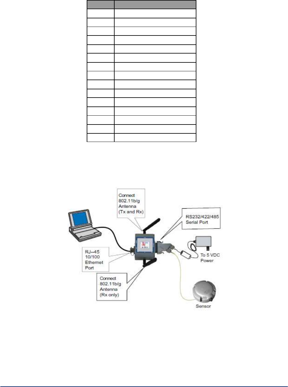
AirGuard WiMesh 3e-523 Series User’s Guide
Copyright 2015 Ultra Electronics, 3eTI
October 2015
84
29000169-005 Revision C1
Table 13 - DB-15 Pin Out Information
Pin
Name
1
COM 0 TX
2
COM 0 NCTS
3
Signal GND
4
RS-485 TX–
5
RS-485 RX–
6
Power RTN
7
Power RTN
8
Power RTN
9
COM 0 RX
10
COM 0 NRTS
11
RS-485 TX+
12
RS-485 RX+
13
Power RTN
14
+5 VDC
15
+5 VDC
Figure 77 below illustrates the setup.
Figure 77 - Setup
3.1.2 Indoor Accessory Kit Installation
The indoor accessory kit (3e-523-IAK) contains the following items:
Qty 2 - R-SMA antennas
DB-15 connector housing with power supply
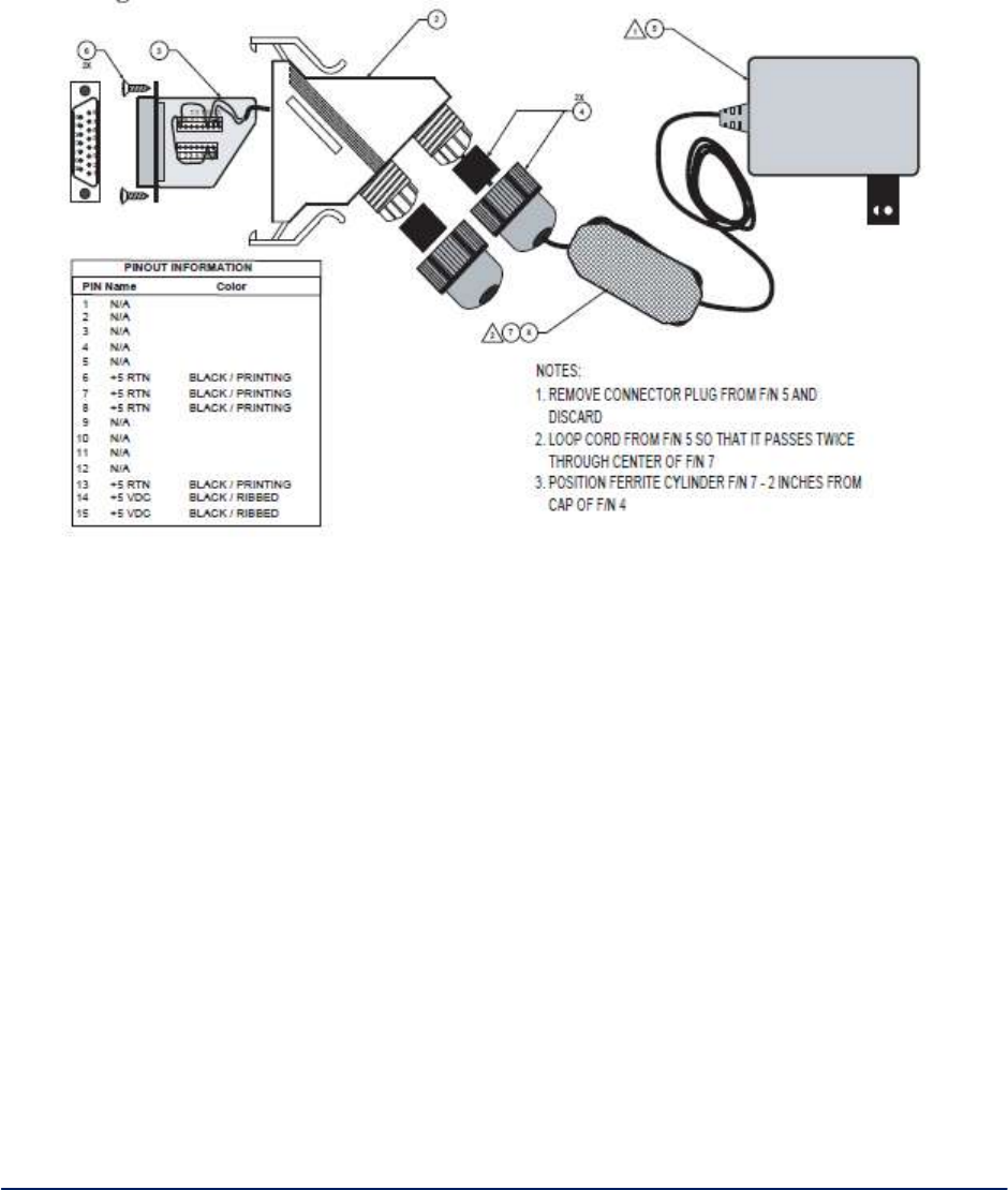
AirGuard WiMesh 3e-523 Series User’s Guide
Copyright 2015 Ultra Electronics, 3eTI
October 2015
85
29000169-005 Revision C1
Assemble the DB-15 connector for power and serial data signals. It is intended that the conductors
intended for +5 VDC Power and Serial Data be routed through the compression nuts and sleeve inserts
before entering the larger connector housing. Refer to Figure 78 below which illustrates the connector
housing assembly. The example shown shows the wiring for +5 VDC Power.
Figure 78 - Connector housing assembly
3.1.3 Outdoor Accessory Kit Installation
If any portion of this system (enclosure, antennas, cables etc.) is mounted outdoors, it is strongly
recommended that the Outdoor Accessory Kit (523-OAK) for this product be used. This kit contains
lightning arrestors and ground cables designed for this product.
If the system is mounted outdoors where CE Mark certification is required, use of the Outdoor Accessory
Kit (or equivalent) is MANDATORY. Failure to install this protection will void the warranty.
The Outdoor Accessory Kit (3e-523-OAK) contains the following items:
Mounting Plate
Pole Mounting Rear Plate
Qty 2 - Outdoor omni-directional antennas
Qty 2 - Right angle R-SMA to bulkhead N cable assemblies
Qty 2 – Lightning Arrestors
Qty 2 - Ground wires
Qty 4 - 1/4-inch bolts
Qty 4 - 1/4–20 Nut and washer

AirGuard WiMesh 3e-523 Series User’s Guide
Copyright 2015 Ultra Electronics, 3eTI
October 2015
86
29000169-005 Revision C1
Qty 4 - Hex socket cap screws
Hex key wrench tool
DB-15 connector housing with associated parts
Large connector housing
DB-15 screw housing insert
Qty 2 - Rubber sleeves
Qty 2 - Compression nuts
Qty 2 - Flat head #4 self tapping screws
Ferrite cylinder
NOTE: You (the user) are required to ensure that the connection to a proper earth ground is made by
properly certified and authorized personnel and must conform to all applicable codes and regulations.
The materials required to connect to a proper ground are defined by local conditions and must be
procured locally to ensure the correct safety environment is achieved. The cable used to connect to a
proper ground must be AWG 10 or heavier. This cable should be kept as short as possible.
! WARNING !
Do not attempt to install any outdoor equipment during hazardous conditions
such as a thunderstorm, where lightning could strike the equipment or installer.
Failure to follow this warning could result in injury or death.
1. Install two Bulkhead N Cable Assemblies to the Mounting Plate.
2. Install unit on the Mounting Plate using the 4 hex socket cap screws. Orient the unit so that the
larger rectangular bulkhead connector is facing away from the N connectors. Tighten with
included hex key wrench tool.
3. Attach the one ground wire to each Lightning Arrestor. Note that one wire is longer than the
other. Each lightning arrestor has a ring terminal attached, remove and discard this item.
4. Attach both Lightning Arrestors to the N Connectors on the Mounting Plate. Mount the
Lightning Arrestor with the longer ground wire on the right side.
5. Route the ground wires to the ground stud on the unit. Secure with 10-32 Nut. Note that a
wire must be routed from this point to a suitable earth ground.
Assemble DB-15 Connector for power and serial data signals. It is intended that the
conductors intended for +5 VDC Power and Serial Data be routed through the compression
nuts and sleeve inserts before entering the larger connector housing. Refer to Figure 78
below to illustrate connector housing assembly. The example shown shows the wiring for +5
VDC Power. See for pin information for the entire connector.
6. Figure 78To reduce unintentional radio frequency interference (RFI), the +5 volt DC power
provided to the device should be conditioned by passing the wires through the supplied ferrite
cylinder (see Figure 79). Refer to the drawing below for guidance on how to pass the wires
through the ferrite cylinder before terminating into the supplied DB-15 connector housing. The
ferrite cylinder should be placed approximately two inches from the cap of the connector
housing.
7. The Outdoor Accessory Kit can be mounted on a pole using the Pole Mounting Rear Plate.
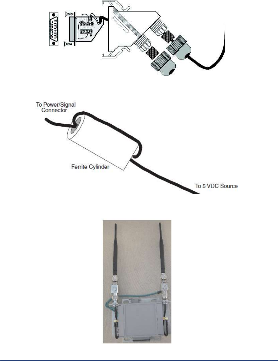
AirGuard WiMesh 3e-523 Series User’s Guide
Copyright 2015 Ultra Electronics, 3eTI
October 2015
87
29000169-005 Revision C1
Figure 78 - Connector housing assembly
Figure 79 - Power conditioning
Figure 80 - Outdoor accessory kit mounting
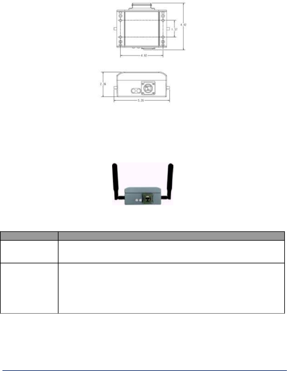
AirGuard WiMesh 3e-523 Series User’s Guide
Copyright 2015 Ultra Electronics, 3eTI
October 2015
88
29000169-005 Revision C1
Next is information on the physical dimensions (Figure 81) of the 3e–523–3 unit.
Figure 81 - 3e-523 dimensions
3.1.4 The Indicator Lights
The side panel of the 3e–523–3 contains two indicator lights (Light Emitting Diodes or LEDs) that help
describe the state of various networking and connection operations (see Figure 82).
Figure 82 - 3e-523 indicator lights
Table 14 - Indicator Lights
LED
Description
FIPS LED (further
from the RJ-45
connector)
The Red LED indicates whether or not the 3e–523–3 is in FIPS mode. When this
LED is lit, the system is in FIPS mode. When not lit, the system is in non-FIPS
mode.
WLAN LED
(next to the RJ-45
connector)
The amber LED is the uplink signal strength, for the bridge or client radio link.
When a strong signal is being received from the remote bridge radio (bridging
mode) or the access point (when in client mode), then the LED will be on steady.
As the received signal becomes weaker, the LED may blink fast for a moderate
signal, blink slowly for a weak signal, or be dark when no connection is made.
When the operating mode of the device is set for access point only mode, this LED
is not used.
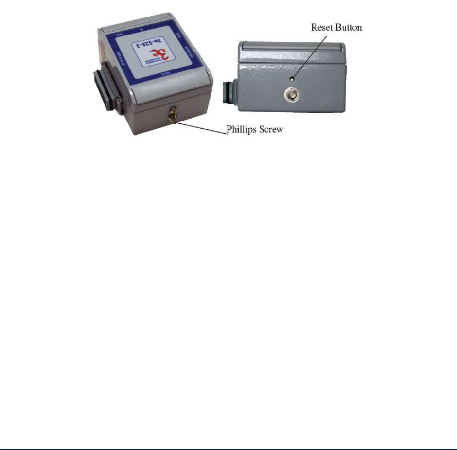
AirGuard WiMesh 3e-523 Series User’s Guide
Copyright 2015 Ultra Electronics, 3eTI
October 2015
89
29000169-005 Revision C1
3.1.5 Reset Button
The reset button is located behind the Phillips (cross-tip) screw on the top side of the unit (Figure 83).
Remove the screw to access the reset button. To reset the unit, use a small screw driver and perform the
following:
1. Push in and hold the reset button for five seconds. Holding the button for more than five (5)
seconds but less than 10 does a reset. Removing power, or going through the web interface
are usually a better ways to reset, when possible. If you hold the button too long, you could
factory default the unit by mistake, and wipe out your configuration.
2. If you continue to hold the button, after 20 seconds the unit will be reset to the factory default.
3. Make sure you reinstall the screw with gasket after using the reset button to keep water out of
the unit.
Figure 83 - Reset button

AirGuard WiMesh 3e-523 Series User’s Guide
Copyright 2015 Ultra Electronics, 3eTI
October 2015
90
29000169-005 Revision C1
3.2 3e-523E-900 Hardware Installation
This section deals with installation of the 3e-523E-900 unit. The unit requires physical mounting and
installation on the site, following a specific placement design ensuring optimum operation.
FCC Regulations require that the 3e-523E-900 product be professionally installed by an installer
certified by the National Association of Radio and Telecommunications Engineers or equivalent
institution.
The package includes the following items:
The Device.
Documentation as PDF files (housed on a CD-ROM).
Registration and Warranty cards.
Minimum System and Component Requirements
To complete the configuration, you must have the following minimal components:
PCs with one of the following operating systems installed: Windows NT 4.0, Windows 2000 or
Windows XP.
Access to at least one laptop or PC with an Ethernet card, and cable that can be used to complete
the initial configuration of the unit.
A Web browser program (such as Microsoft Internet Explorer 6.0 or later, or Netscape 6.3 or later)
installed on the PC or laptop you will be using to configure the Access Point.
3.2.1 Specifications
ELECTRICAL SPECIFICATIONS:
Operating Voltage:
110/220VAC, 50/60Hz
Power Requirements:
5.5 Watts (> 0°C)
15 Watts (< 0°C, internal heaters operating)
External Interfaces:
Ethernet, 10/100, standard RJ-45 interface
N-type female jack antenna connector
Radio Transmission :
902-928 MHz band
ENVIRONMENTAL SPECIFICATIONS:
Operating
Temperature:
-30 to +50°C External Ambient (-22 to +122 °F)
Storage Temperature:
-40 to +70°C (-40 to +158 °F)
Relative Humidity:
90%, non-condensing
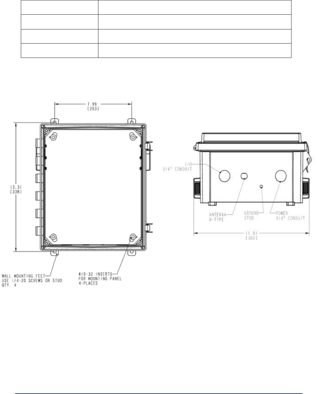
AirGuard WiMesh 3e-523 Series User’s Guide
Copyright 2015 Ultra Electronics, 3eTI
October 2015
91
29000169-005 Revision C1
MECHANICAL / MOUNTING SPECIFICATIONS:
Enclosure:
Polycarbonate, polyurethane gasket, stainless steel hardware
Weight :
8.8 lbs
Features:
Pad-lockable, outdoor deployment (weatherproof)
Dimensions:
12.08” W x 13.57” H x 6.95” D
3.2.2 Mounting Pattern
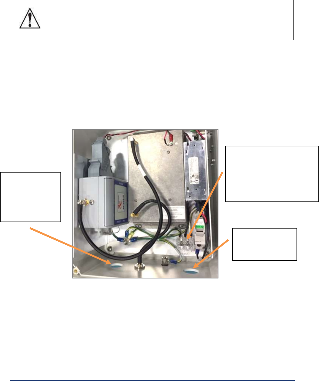
AirGuard WiMesh 3e-523 Series User’s Guide
Copyright 2015 Ultra Electronics, 3eTI
October 2015
92
29000169-005 Revision C1
3.2.3 Installation Requirements
! WARNING !
Do not attempt to install any outdoor equipment during hazardous conditions such
as a thunderstorm, where lightning could strike the equipment or installer. Failure
to follow this warning could result in injury or death.
Mounting feet (and screws) are supplied with the unit, attached inside of the cover. Installer must
attach these to the enclosure prior to mounting.
Drill holes per mounting pattern drawing and fasten with ¼” screws or bolts (provided by the
installer), as appropriate for the installation.
AC power cabling and cable gland (or conduit and hub) are to be provided by the installer as
appropriate. Two cutouts provided, one for signal wire, one for power wiring, each at 1.109”
diameter. Both holes must have appropriate cable glands or conduit hubs added for weatherproof
installation.
External grounding wire is not provided with the unit. Protection for the user and unit require a
minimum 10AWG safety ground be attached to the threaded stud at the bottom of the unit to a
secure earth bonded surface. The length of this grounding wire should be kept to a minimum, 3eTI
recommends less than 3 feet.
NOTE: You (the user) are required to ensure that the connection to a proper earth ground is
made by properly certified and authorized personnel and must conform to all applicable codes
and regulations. The materials required to connect to a proper ground are defined by local
conditions and must be procured locally to ensure the correct safety environment is achieved.
Install power cable
gland or conduit
hub, as appropriate.
Install AC wiring per label.
Ground to “G”, Line (black) to
“L”, Neutral (white) to “N”
terminals.
Secure wires with gland/hub.
Install cable gland
or conduit hub, as
appropriate for
data cables and/or
weather seal.

AirGuard WiMesh 3e-523 Series User’s Guide
Copyright 2015 Ultra Electronics, 3eTI
October 2015
93
29000169-005 Revision C1
The cable used to connect to a proper ground must be AWG 10 or heavier. This cable should
be kept as short as possible.
3.2.4 RF Connections
NOTE: This radio transmitter IC: 6780A-523E900 has been approved by Industry Canada to operate with
the antenna types listed below with the maximum permissible gain indicated. Antenna types not included
in this list, having a gain greater than the maximum gain indicated for that type, are strictly prohibited for
use with this device.
L-Com HGV906U, 6-dBi gain, Omni-Directional antenna
L-Com HG906YE, 6-dBi gain, Yagi antenna
RF cabling, lightning arrester, and antenna are not provided with the unit.
The installer should provide a suitable lightning arrestor that can attach directly to the
N-male RF port at the bottom of the unit. Ground the lightning arrestor to the same earth
bonded ground attachment as used for the unit.
The installer should provide a suitable antenna to meet the RF coverage needs per
application.
LMR-400 cabling is recommended for longer than 10 feet of external RF cabling. Ensure
this cable is routed and tied down to avoid undue mechanical stress on the lightning
arrestor attached to the unit.
3.2.5 RF Safety Information
FCC: To comply with FCC RF exposure compliance requirements, the antennas used with
the 3e-523E-900 product must be installed with a minimum separation distance of 21.5 cm
from all persons and must not be co-located or operated in conjunction with any other
antenna or transmitter. Installation should be accomplished using the authorized cables
and / or connectors provided with the device or available from the manufacturer / distributor
for use with this device. Changes or modifications not expressly approved by the
manufacturer or party responsible for this FCC compliance could void the user’s authority to
operate the equipment.
Industry Canada: To comply with Industry Canada RF Exposure requirements, the antennas
used with the 3e-523E-900 product must be installed with a minimum separation distance of
32 cm from all persons.
NOTE: This equipment has been tested and found to comply with part 15 of the FCC Rules.
These limits are designed to provide reasonable protection against harmful interference
when the equipment is operated in a commercial environment. This equipment generates,
uses, and can radiate radio frequency energy and, if not installed and used in accordance to
the instruction manual, may cause harmful interference to radio communications. Operation
of this equipment in a residential area is likely to cause harmful interference in which case the
user will be required to correct the interference at their own expense.
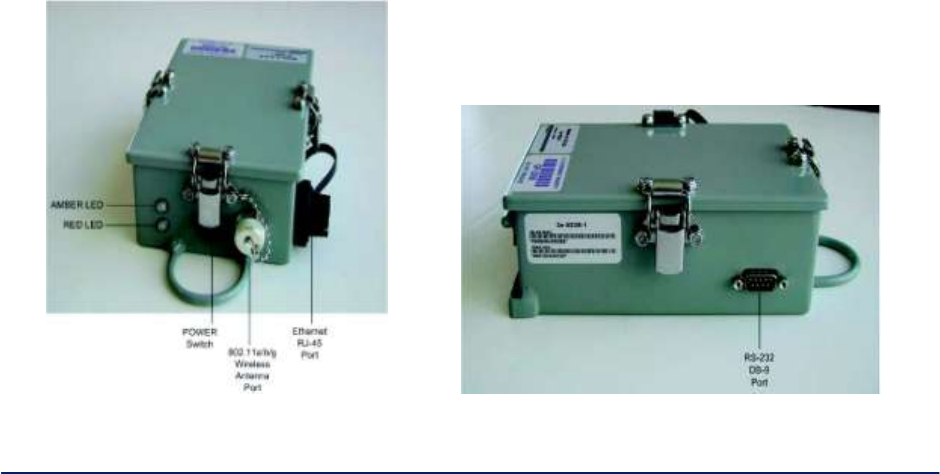
AirGuard WiMesh 3e-523 Series User’s Guide
Copyright 2015 Ultra Electronics, 3eTI
October 2015
94
29000169-005 Revision C
4. WiMesh PAC-Link (3e-523S) Hardware Overview
The 3e–523S, also called the Portable Adaptive Com-Link (PAC-Link), is an extremely portable, battery
operated IP router used in mobile operations. The 3e–523S is intended to provide mobile IP connectivity
for personnel on the move when the RF signal strength cannot be maintained to the base operations
center. When the RF signal is disrupted, a 3e–523S can be used as a repeater which when situated in a
suitable location, will provide suitable RF signal strength between the personnel and the base operations
center.
Multiple 3e–523S units can provide secure communications between personnel and the base operations
center when large structures are penetrated or around the perimeter of large objects by simply tying the
3e–523S units to railings or other convenient tie points as the progress of personnel takes them beyond
the signal range of the last 3e–523S–1 that was deployed. In this way, connectivity can be maintained
between personnel and the base operations center.
Inside the 3e–523S is the FIPS 140-2 Validated 3e–523M multifunction wireless data module. Also
included is a rechargeable lithium-ion battery with a battery charge of approximately eight hours. The
3e–523S supports three different operating modes:
Wireless Access Point (WAP)
Wireless Client (STA)
Wireless Bridge (WDS)
The 3e–523S can be configured for FIPS or non-FIPS sub-mode. In addition, the 3e–523S supports
802.11i and Wi-Fi Protected Access 2 (WPA2), WPA and different EAP types, Temporal Key Integrity
Protocol (TKIP) for WPA encryption and Advanced Encryption Standard (AES) for WPA2 encryption. With
support of 802.11a/b/g standards, the 3e–523S delivers up to 22 Mbps of sustained data rate in 5 GHz and
2.4 GHz bands.
Figure 84 below shows the Antenna and Ethernet sides of the 3e523S device.
Figure 84 - 3e-523S Device (Antenna side) on left and 3e-523S Device (RS-232 side) on right.
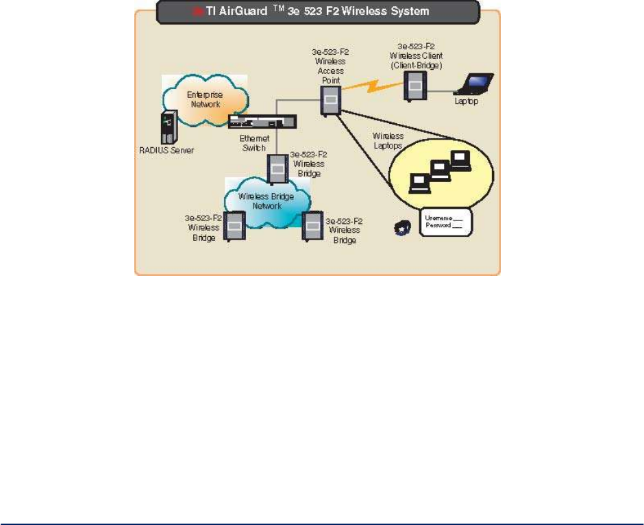
AirGuard WiMesh 3e-523 Series User’s Guide
Copyright 2015 Ultra Electronics, 3eTI
October 2015
95
29000169-005 Revision C1
5. WiMesh End Point OEM Module (3e-523M)
The 3e–523M is a secure multi-function wireless OEM Module which can be integrated into another
product.
The 3e–523M supports four different operating modes:
Wireless Access Point (WAP)
Wireless AP and Bridge simultaneous mode
Wireless Client (STA)
Wireless Bridge (WDS)
The 3e–523M also can be configured for FIPS or non-FIPS sub mode. In addition, the 3e–523M supports
802.11i and Wi-Fi Protected Access 2 (WPA2), WPA and different EAP types. Temporal Key Integrity
Protocol (TKIP) for WPA encryption and Advanced Encryption Standard (AES) for WPA2 encryption.
With support of 802.11b/g/a standards, the 3e–523M delivers up to 54Mbps of data rate in 5GHz and 2.4
GHz bands. Figure 85 below illustrates a wireless system using the 3e–523M in all three modes.
Figure 85 - 3e-523M wireless system
Wireless Access Point Mode
In the wireless access point mode, you can use the 3e–523M to connect wireless communication devices
together to create a wireless network. The 3e–523M is usually connected to a wired network and can relay
data between devices on each side. Many 3e–523Ms can be connected together to create a larger
network that allows roaming (
Figure 86).
In Wireless Access Point (WAP) mode the WAN interface has to connect to a backbone Ethernet switch in
order to operate normally. It bridges the backbone Ethernet network and wireless interface.
Figure 86 below shows how to setup the Ethernet cable and IP addressing.
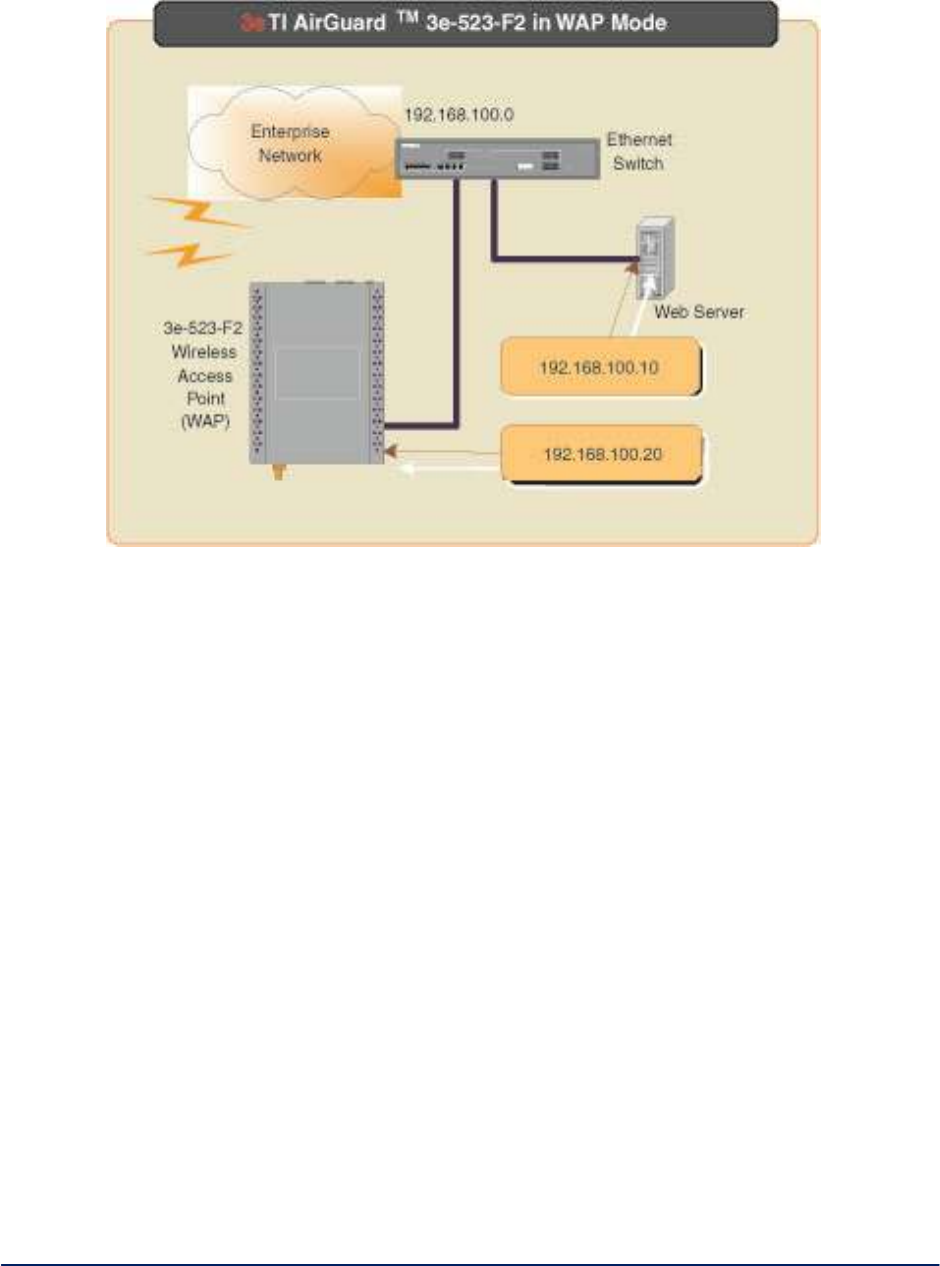
AirGuard WiMesh 3e-523 Series User’s Guide
Copyright 2015 Ultra Electronics, 3eTI
October 2015
96
29000169-005 Revision C1
Figure 86 - 3e-523M wireless access point mode
There are numerous security methods provided in this mode. In non-FIPS mode: WEP, WPA (TKIP and
AES-CCM) and WPA2 (TKIP and AES-CCM) are available. The 3e–523M also supports EAP-MD5,
EAP-TTLS, EAP-TLS, PEAP, EAP-SIM protocols. In FIPS mode: static 128-, 192- and 256-bit AES, static
3DES and FIPS 802.11i are available.
WPA is a subset of 802.11i that satisfies some of the requirements of the full 802.11i standard. Some of
the significant features of WPA are:
1. It supports two authenticated key management protocols in infrastructure mode using 802.1X
with pre-shared key and with EAP authentication. The IBSS approach described uses no
authenticated key management protocol but uses a pre-shared key directly as the
encryption/integrity key.
2. APs and stations use IEEE 802.11 open authentication when they use WPA.
3. APs must advertise what they support (Cipher suite, authentication modes). Stations must
request the cipher suites and authenticated key management protocol they want. A propriety
information element in the Beacon and probe response messages is used
to carry this information. The station uses the same information element in association request
message.
4. Authentication and Association are required.
5. TKIP encryption with the Michael integrity check is required.
Wireless Bridging Mode
In Wireless Bridging (WDS) mode the WAN interface may or may not need to connect to a backbone
Ethernet switch. It depends on needs of infrastructure network. However, wireless bridging extends the
network from an existing wired network easily without altering the network topology.
Figure 87 below shows how to setup the Ethernet cable and IP addressing.
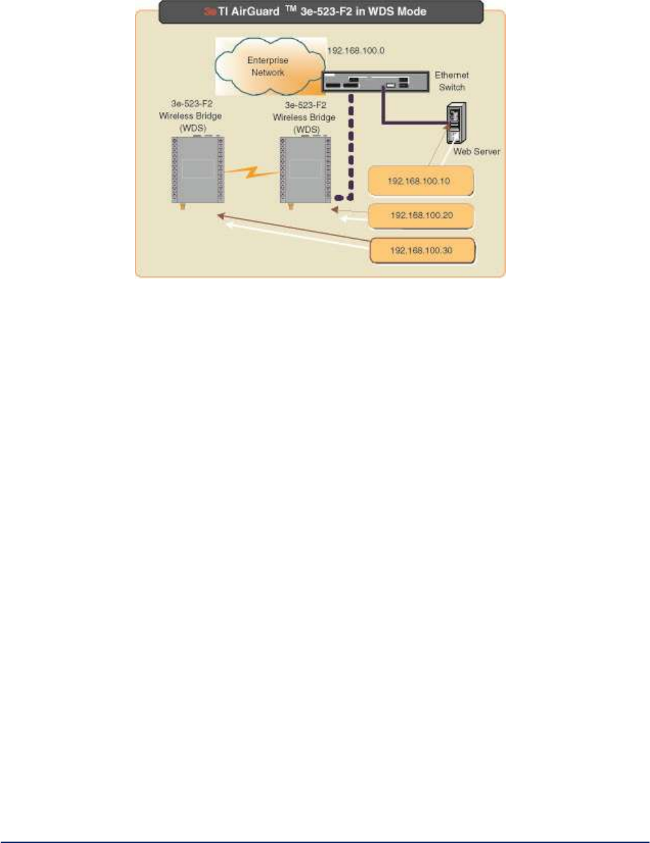
AirGuard WiMesh 3e-523 Series User’s Guide
Copyright 2015 Ultra Electronics, 3eTI
October 2015
97
29000169-005 Revision C1
Figure 87 - 3e-523-F2 wireless bridging mode
This type of infrastructure is decentralized. As each node needs only transmit as far as the next node.
Nodes act as repeaters to transmit data from nearby nodes to peers that are too far away to reach,
resulting in a network that can span large distances.
The 3e–523M in bridging mode provides point-to-point or point-to-multipoint network topology.
In bridging mode, the 3e–523M can be configured for FIPS or non-FIPS mode.
In non-FIPS mode the 3e–523M supports AES-CCM for security. In FIPS mode, the 3e–523M supports
Static 128-, 192- and 256-bit AES and static 3DES.
Wireless Client Mode
In Wireless Client/Client-Bridge mode, the WAN interface is NOT design for a backbone network
connection. It is the interface for computer connected to it. The following diagram shows how to setup the
Ethernet cable and IP addressing (Figure 88).
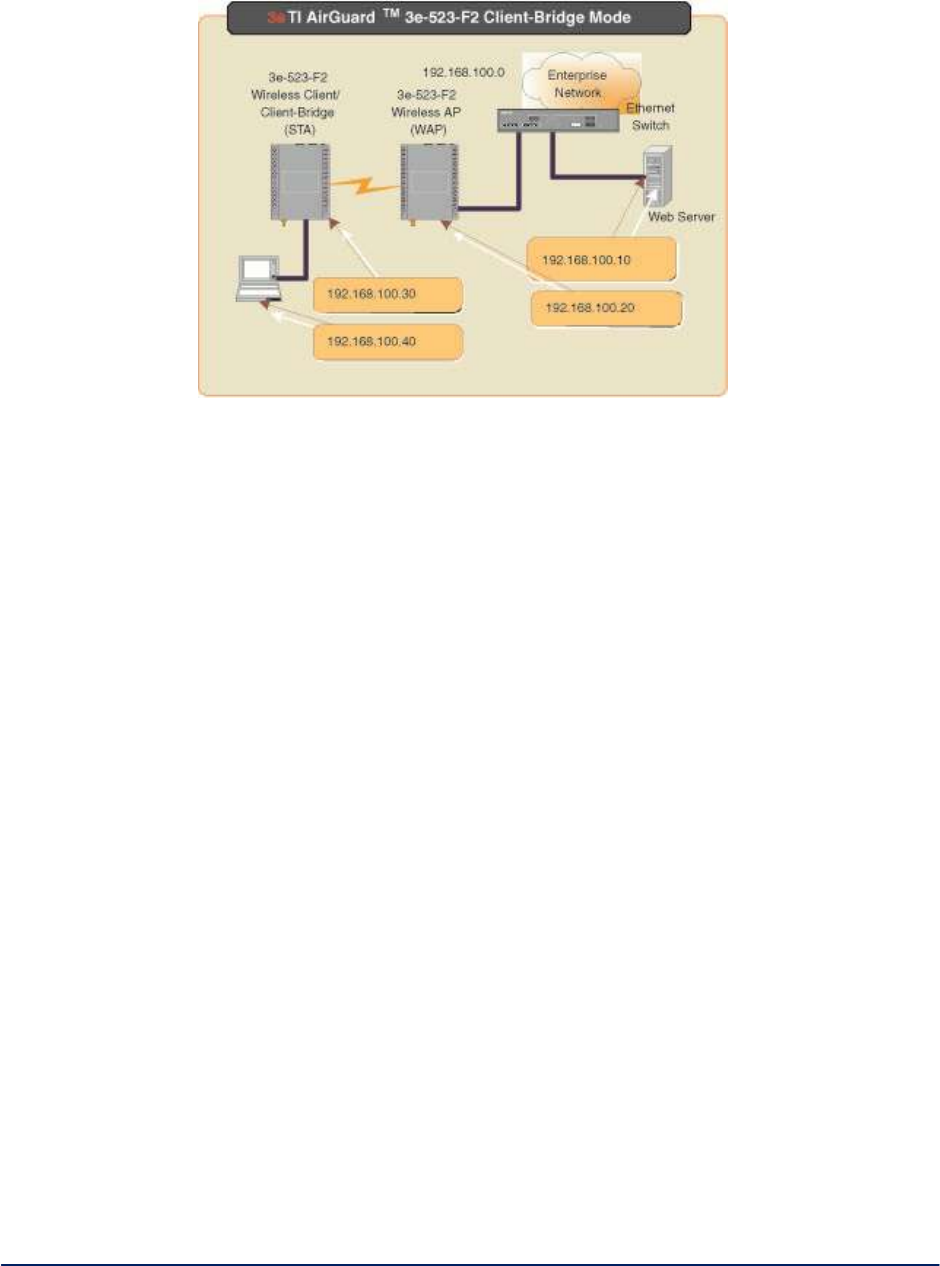
AirGuard WiMesh 3e-523 Series User’s Guide
Copyright 2015 Ultra Electronics, 3eTI
October 2015
98
29000169-005 Revision C1
Figure 88 - Wireless client mode
The 3e–523M can operate as a client device that communicates with a wireless access point. It supports
802.11a/b/g bands.
In client mode, the 3e–523M can be configured for FIPS or non-FIPS mode.
In non-FIPS mode the 3e–523M supports AES-CCM for security. In FIPS mode, the 3e–523M supports
Static 128-, 192- and 256-bit AES and static 3DES.
Network Topology Map Enhancement
The 3e–523M contains an embedded network topology map ( 89 111) which can help you to envision the
bridged network. The initial implementation provides the following tree structure where each indented entry
is a child to the entry above it. The entry at the top of the tree is the STP root. The receive signal strength is
indicated by the % on each link.
The map shows the network layer 2 topology. APs that are part of another network are not displayed in the
map. This map only reports all 3eTI devices (client-bridge, AP, bridge) and part of 3rd party switches
running STP. 3eTI strongly recommends that you configure your 3rd party switch as root and make it the
uplink for the 3eTI device cloud to the backbone network.
This implementation is base-on the current design.

AirGuard WiMesh 3e-523 Series User’s Guide
Copyright 2015 Ultra Electronics, 3eTI
October 2015
99
29000169-005 Revision C1
Figure 89 - Network topology map
Hardware Installation
The 3e-523M has multiple wired interfaces and functions available via the exposed connectors (Figure
90). These interface features on connector P1 consist of a Serial RS-232/422/485 IO port that also
contains the power interface. Connector P2 contains the Reset Function, LED Indicators as well as
advanced features to be activated in future revisions. There is a standard 10/100 RJ-45 Ethernet port.
The wireless interface consists of one 802.11 a/b/g dual antenna wireless interface for diversity. It uses
standard 50-ohm SMA connectors.
The Reset Function is activated by shorting P2 - pin 1 to GND found at P2 – pin 7 or 8.
Short for 5 seconds and release – simple reset, you can also power cycle the module
Short for 11 seconds and release – resets all to factory defaults. This can be used when there’s no
GUI access to the module.
The 3.3 VDC pins shown on P2 – pins 3 and 4 are only to be used as a current source to illuminate any
external LED indicators the user wishes to connect. DO NOT ATTEMPT TO SOURCE 3.3 VDC TO THE
3e523M THROUGH P2. This will void the warranty, damage the unit and may create a safety hazard.
The LED Indicator signals are capable of sinking approximately 9 mA using the supplied +3.3 VDC from
pins 3 and 4 of P2. Refer to the following Figure 91 to view the connection for these signals. Each LED
Indicator signal from the 3e-523M processor contains a 287 ohm current limiting resistor, so no additional
resistor is typically required.
Power requirements: +5VDC +-5% 3 Amps
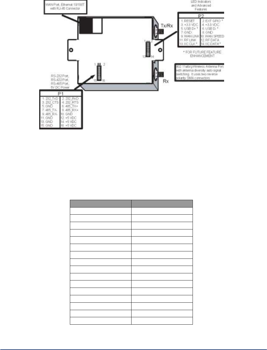
AirGuard WiMesh 3e-523 Series User’s Guide
Copyright 2015 Ultra Electronics, 3eTI
October 2015
100
29000169-005 Revision C1
Figure 90 - Hardware Installation
The 3e-523M unit can be used for either RS232 communications or for RS485/422 communications, but
the two functions are mutually exclusive as they share a common UART. The pinout information for the
P1 serial port is shown in Table 15 below.
NOTE: For a rugged environment, the user should consider adding RTV to enforce the connectors.
Table 15 - P1 Pin Out Information
Pin Number
Serial Port Functionality
1
RS232 TxD
2
RS232 RxD
3
RS232 CTS
4
RS232 RTS
5
GND
6
RS485 TX+
7
RS485 TX
8
RS485 RX+
9
RS485 RX
10
GND
11
GND
12
+5VDC
13
GND
14
+5VDC
15
GND
16
+5VDC
When the 3e-523M unit is run in full RS485 duplex mode each 485 signal pair is connected separately and
when the interface is run in half duplex mode the Tx+/Rx+ and Tx-/Rx- wires are connected together.
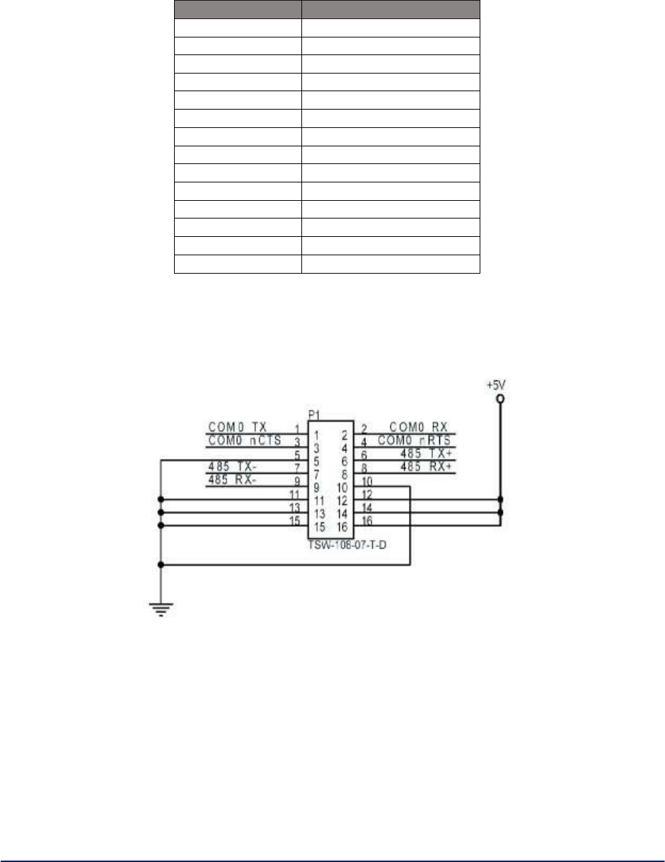
AirGuard WiMesh 3e-523 Series User’s Guide
Copyright 2015 Ultra Electronics, 3eTI
October 2015
101
29000169-005 Revision C1
The P2 serial port is used for LED indicators and advanced features. See Table 16
Table 16 - P2 Pin Out Information
Pin Number
Serial Port Functionality
1
RESET
2
EXT GPIO
3
+3.3 VDC
4
+3.3 VDC
5
USV D+
6
USB D
7
GND
8
GND
9
WAN LINK
10
WAN SPEED
11
RF LINK
12
RF DATA
13
IIC CLK
14
IIC DATA
Pin Definition and schematics of the P1 serial port and power, 16 pin, double row, 100 mil header is
illustrated in Figure 91 below.
Figure 91 - P1 Pin setup
Pin Definition and schematics of the P2 serial port and LED, 14 pin, double row, 100 mil header (Figure
92).
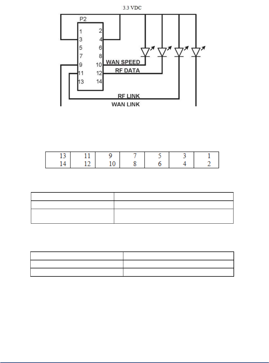
AirGuard WiMesh 3e-523 Series User’s Guide
Copyright 2015 Ultra Electronics, 3eTI
October 2015
102
29000169-005 Revision C1
Figure 92 - P2 Pin setup
Top view of P2 connector, the Pin 1 is closer to the Tx/Rx antenna connector (Figure 93). Table 17 and
Table 18 below lists the mating connectors. Figure 93
Figure 93. Top View of P2 Connector
Table 17 - Mating Connector
Digi-Key Part Number
WM2524-ND
Manufacturer Part Number
022-55-2141
Description
CONN RECEPT HOUSING 14POS .100
inch
Table 18 - Mating Connector Contact Pin
Digi-Key Part Number
WM2511-ND
Manufacturer Part Number
16-02-0096
Description
CONN SOCKET CRIMP 24-30AWG TIN
Pin Definition (Figure 94) and color code (Figure 95) for RJ45 of Ethernet port.
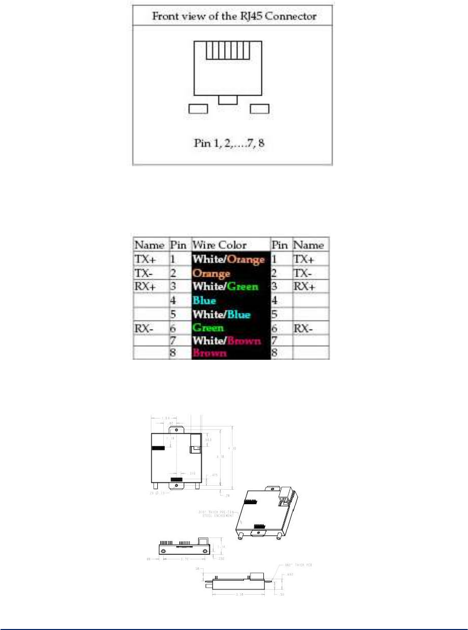
AirGuard WiMesh 3e-523 Series User’s Guide
Copyright 2015 Ultra Electronics, 3eTI
October 2015
103
29000169-005 Revision C1
Figure 94 - Front view of RJ45 connector
RJ45 connector signal names and color code per IEEE 802.3 spec. Figure 95 illustrates the mechanical
drawing of 3e-523-F2.
Figure 95 - RJ45 connector signal names and color code
5.1.1 Mechanical Drawings
Figure 96 - Mechanical drawing of 3e-523-F2

AirGuard WiMesh 3e-523 Series User’s Guide
Copyright 2015 Ultra Electronics, 3eTI
October 2015
104
29000169-005 Revision C1
6. Technical Support
Manufacturer’s Statement
3e–523 is provided with a standard warranty. It is not desired or expected that the user open the device. If
a malfunction is experienced and all external causes are eliminated, the user should contact 3eTI for
instructions on how to resolve the issue
If you are experiencing trouble with this unit, the point of contact is:
e-mail: support@3eti.com
Phone: 1-800-449-3384 (Monday - Friday)
or visit our website at www.ultra-3eti.com
Radio Frequency Interference Requirements
This device has been tested and found to comply with the limits for a Class A digital device, pursuant to
Part 15 of the Federal Communications Commission’s Rules and Regulations. These limits are designed
to provide reasonable protection against harmful interference when the equipment is operated in a
commercial environment. This equipment generates, uses, and can radiate radio frequency energy and, if
not installed and used in accordance with the instruction manual, may cause harmful interference to radio
communications. Operation of this equipment in a residential area is likely to cause harmful interference in
which case the user will be required to correct the interference at their expense.
Installation should be accomplished using the authorized cables and/or connectors provided with the
device or available from the manufacturer/distributor for use with this device. Changes or modifications not
expressly approved by the manufacturer or party responsible for this FCC compliance could void the
user’s authority to operate the equipment.

AirGuard WiMesh 3e-523 Series User’s Guide
Copyright 2015 Ultra Electronics, 3eTI
October 2015
105
29000169-005 Revision C1
Appendix A: Glossary
3DES - Also referred to as Triple DES, a mode of the DES encryption algorithm that encrypts data three
times.
802.11 - 802.11 refers to a family of specifications developed by the IEEE for wireless LAN technology.
802.11 specifies an over-the-air interface between a wireless client and a base station or between two
wireless clients. The IEEE accepted the specification in 1997.
Access Point - An access point is a gateway set up to allow a group of LAN users access to another
group or a main group. The access point doesn’t use the DHCP server function and therefore accepts IP
address assignment from the controlling network.
AES - Short for Advanced Encryption Standard, a symmetric 128-bit block data encryption technique
developed by Belgian cryptographers Joan Daemen and Vincent Rijmen. The U.S government adopted
the algorithm as its encryption technique in October 2000, replacing the DES encryption it used. AES
works at multiple network layers simultaneously.
Bridge - A device that connects two local-area networks (LANs), or two segments of the same LAN that
use the same protocol, such as Ethernet or Token-Ring.
DHCP - Short for Dynamic Host Configuration Protocol, DHCP is a protocol for assigning dynamic IP
addresses to devices on a network. With dynamic addressing, a device can have a different IP address
every time it connects to the network. In some systems, the device’s IP address can even change while it
is still connected. DHCP also supports a mix of static and dynamic IP addresses. Dynamic addressing
simplifies network administration because the software keeps track of IP addresses rather than requiring
an administrator to manage the task. This means that a new computer can be added to a network without
the hassle of manually assigning it a unique IP address. Many ISPs use dynamic IP addressing for dial-up
users.
NMS (Network Management Station) - Includes such management software as HP Openview and IBM
Netview.
PC Card - A computer device packaged in a small card about the size of a credit card and conforming to
the PCMCIA standard.
PDA (Personal Digital Assistant) - A handheld device.
SNMP (Simple Network Management Protocol) - A Network ID unique to a network. Only clients and
access points that share the same SSID are able to communicate with each other. This string is
case-sensitive. Wireless LANs offer several security options, but increasing the security also means
increasing the time spent managing the system. Encryption is the key. The biggest threat is from intruders
coming into the LAN. You set a seven-digit alphanumeric security code, called an SSID, in each wireless
device and they thereafter operate as a group.
WLAN (Wireless Local Area Network) - A type of local-area network that uses high-frequency radio
waves rather than wires to communicate between nodes.
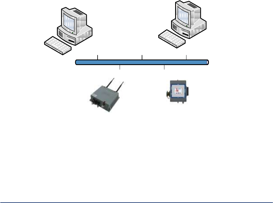
AirGuard WiMesh 3e-523 Series User’s Guide
Copyright 2015 Ultra Electronics, 3eTI
October 2015
106
29000169-005 Revision C1
Appendix B: Two-Factor Authentication Overview and
Configuration
B.1 Overview and Operation
Two-factor authentication is the method of using two independent methods to increase the assurance that
a user has been authorized to access a secure device. 3eTI devices have the ability to provide increased
authentication assurance by providing for a user requiring 3eTI device access to be authenticated first via
a centralized validation authority and user login / password access for a particular device. The 3eTI Data
Points support Public Key Certificates issues and managed by a Certificate Authority. By networking
3eTI devices into a Public Key Infrastructure, a 3eTI Data Point can use the capabilities of the PKI network
by requiring a user to first validate authentication capabilities using a Common Access Card (CAC) card
and the PKI network when using a computer to gain access to the 3eTI Data Point. Once permission is
granted through the PKI network a user then uses their login ID and password to gain access to the 3eTI
device.
Since the exact method of implementing and managing a PKI network may vary based on organization the
following section provides details on how a 3eTI Data Point may be configured for two-factor
authentication based on internal 3eTI configuration and testing of this feature. The following defines how to
configure and use a Public Key Infrastructure (PKI) to manage and configure a 3e-523 Data Point. See
Figure 97 for a block level overview of a PKI network.
Figure 97 – Two-Factor Authentication PKI Network Overview
When enabled, a user with a valid Common Access Card (CAC) is authenticated through an existing PKI
network to gain an access to a 3eTI Data Points web management interface. The 3eTI Data Point uses the
Online Certificate Status Protocol (OCSP) to send requests to an OCSP Responder in the PKI network.
Based on the information returned from the OCSP Responder, the Data Point determines if the users has
permission to access the web management GUI of the device. Based on the current permission setting of
the requestor, the OCSP responder will return receive one of three possible statuses in response to a
request to check CAC certificates validity. The status in the response the Data Point can be unknown,
revoked, or good.
Web
Client
3e-525
Family of
Products
OCSP
Responder
3e-523
Family of
Products
IP
Network

AirGuard WiMesh 3e-523 Series User’s Guide
Copyright 2015 Ultra Electronics, 3eTI
October 2015
107
29000169-005 Revision C1
If the OCSP Responder does not have access to a valid Certificate Revocation List (CRL) for the
Certificate Authority (CA) owning the requesting CAC certificate then the status returned will be unknown.
The unknown certificate status is treated by the AP as if the client certificate was invalid. If the responder
has access to a valid CRL for the CA owning the certificate then the status depends upon whether or not
the certificate is listed in the CRL as revoked. If revoked then the status returned is revoked, otherwise the
status will be good. If the response returned is invalid or revoked the Data Point will not allow the
requestor to login to the web management interface. If the response is good the Data Point provides the
Login and password interface to the requestor.
PKI Network Components
The following components are required to implement and operate a PKI network providing Two-Factor
authentication of 3eTI Data Points, see Figure 97 – for the components that make up a PKI network.
Web Client
A computer running a valid Web client / browser (Internet Explorer 6 or later) that is able to communicate
to the Data Point thought either its LAN or WAN port. The web client PC must be running Windows XP
SP3 or later and be equipped with smart card slot. The computer must have software installed that can
read and process CAC card information. Also, the requestor must have a valid Common Access Card
(CAC) (DoD CA-23) that will return a status of good from the OCSP Responder. Software such as ActivI-
dentity ActivClient (6.2 or later) will meet system requirements.
OCSP Responder
The OCSP Responder provides remote access to Certificate Revocation List (CRL) databases via the
OCSP protocol. The responder is meant to aggregate and help manage large databases and control how
a CRL is stored and managed within the network. Software such as Tumbleweed Validation Authority (4.9)
running on Windows Server 2003 R2 platform is recommended. DoD CA-23 certificate and any
corresponding CRL can be loaded to the OCSP Responder from a local file. Current DoD certificates and
CRLs can be obtained from https://crl.chamb.disa.mil/. See Table 19 for the network component
operational requirements.
Table 19 - PKI Network Component Requirements
System Element
Operational Requirements
Web Client
Internet Explorer 6.0 or later, running on Windows XP
SP3 or later.
PC with smart card slot and ActivIdentity ActivClient (or
similar) 6.2 or later software installed.
DoD issued Common Access Card (CAC).
OCSP Responder
Windows Server 2003 R2
Tumbleweed Valicert Validation Authority 4.9 or later
3eTI Data Points
Software Release 4.4 or later, valid for both 3e-523 and
3e-525 series of products
B.2 Configuration of 3eTI Data Points for Two-Factor Authentication
Configuring OCSP operation on 3eTI Data Points
By default, OCSP is disabled. The following steps show how to enable and configure OCSP on 3eTI
devices.

AirGuard WiMesh 3e-523 Series User’s Guide
Copyright 2015 Ultra Electronics, 3eTI
October 2015
108
29000169-005 Revision C1
Login onto the device and navigate to the User Login Policy web page, as shown in Figure 98.
In order to start using OCSP, the CA certificate (DoD CA-23 certificate) that will used to issue / sign the
CAC certificates must be uploaded to the AP.
IMPORTANT NOTE: The CA certificate file must be in PEM format. DoD certificates downloaded from the
DoD PKI Management web site (https://crl.chamb.disa.mil/) are typically received in the X.509 format
(*.cer), if this is true the file will need to be converted to PEM format first. This can be accomplished using
the OpenSSL utility that comes pre-installed on most Linux distributions or can be uploaded from the
internet:
The command for converting from X.509 format to PEM format is
OpenSSL x509 -inform der -in DODCA_23.cer -out DODCA_23.pem
Click the Load New Certificate link on the User Login Policy web page. This will take you to the
“Update OCSP Certificate” web page shown in Figure 98
Click on the Browse button and navigate to the CA certificate file using the Choose File to Upload
screen, select the file and click the Open button, see Figure 99.
After the CA file in PEM format is selected, click the Upload Cert button, on the web page. A
warning pop up window will be displayed, see Figure 100.
IMPORTANT: Read the warning message carefully. If the CA certificate file is not correct and does not
match the certificate on the CAC card and/or is not the same as what is installed on OCSP Responder the
connection to web management interface of the 3eTI device may not be possible.
WARNING: If the web client/AP/OCSP Responder are configured incorrectly, or there is no network
connection to the Validation Authority software / OCSP Responder, the web client will not be able to
access the device web GUI. If this occurs setting the 3eTI Data Point to its factory default configuration will
disable OCSP, allowing a user to connect to device web GUI using factory default settings.
Click the OK button of the pop up window. If the upload is successful the message page shown in
Figure 101 will be displayed.
– Click Back button. This will take you back to the User Login Policy web page, Figure 98
. The User Login Policy page will show information related to the uploaded CA under the OCSP
Certificate banner on the page.
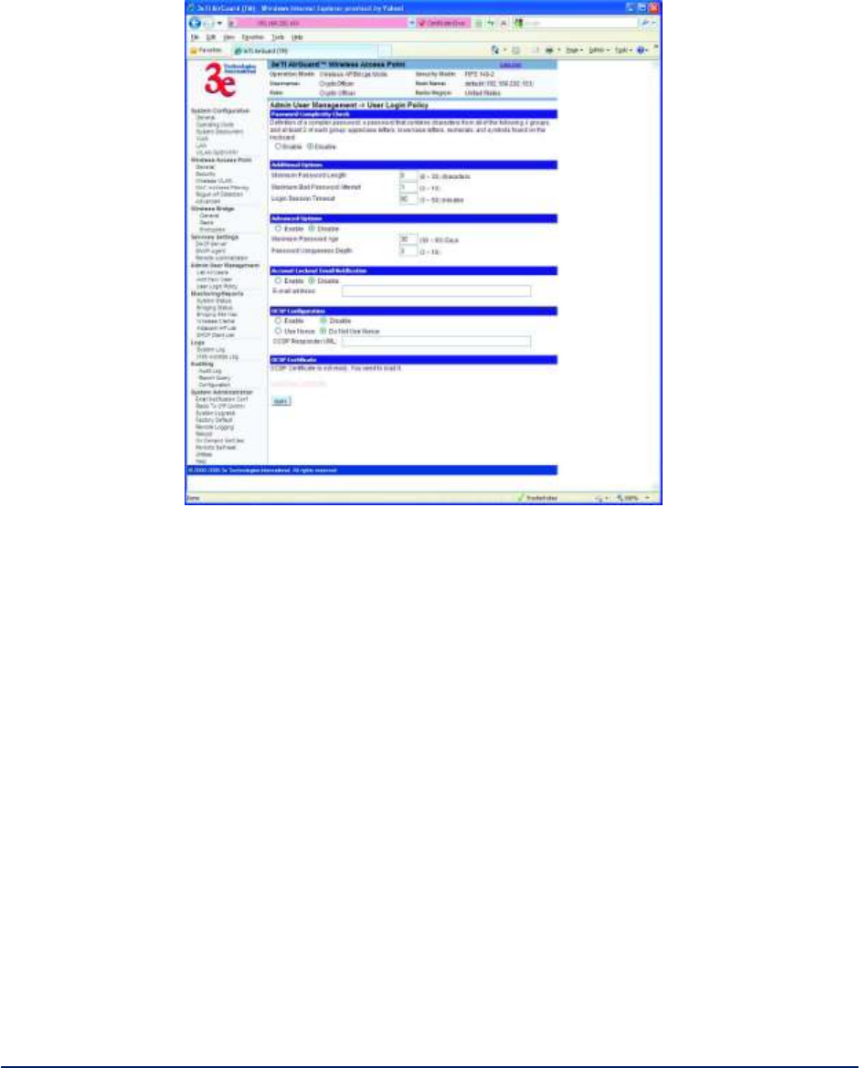
AirGuard WiMesh 3e-523 Series User’s Guide
Copyright 2015 Ultra Electronics, 3eTI
October 2015
109
29000169-005 Revision C1
Figure 98 - User Login Policy Page
Figure 99 - Loading OCSP Certificate File
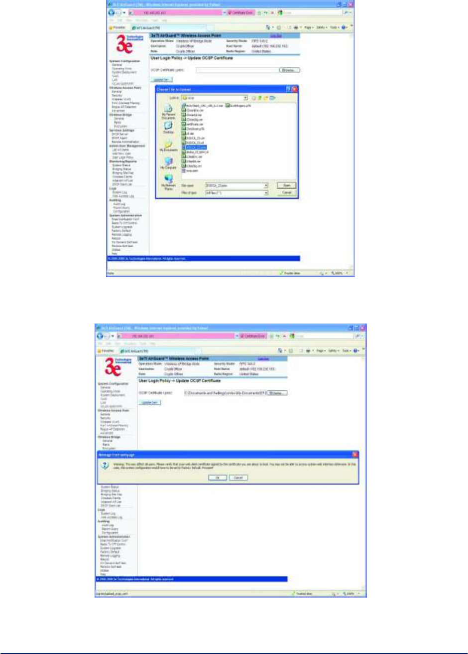
AirGuard WiMesh 3e-523 Series User’s Guide
Copyright 2015 Ultra Electronics, 3eTI
October 2015
110
29000169-005 Revision C1
Figure 100 - OCSP Certificate File Warning
Figure 101 - OCSP Certificate File Upload Success Message Page

AirGuard WiMesh 3e-523 Series User’s Guide
Copyright 2015 Ultra Electronics, 3eTI
October 2015
111
29000169-005 Revision C1
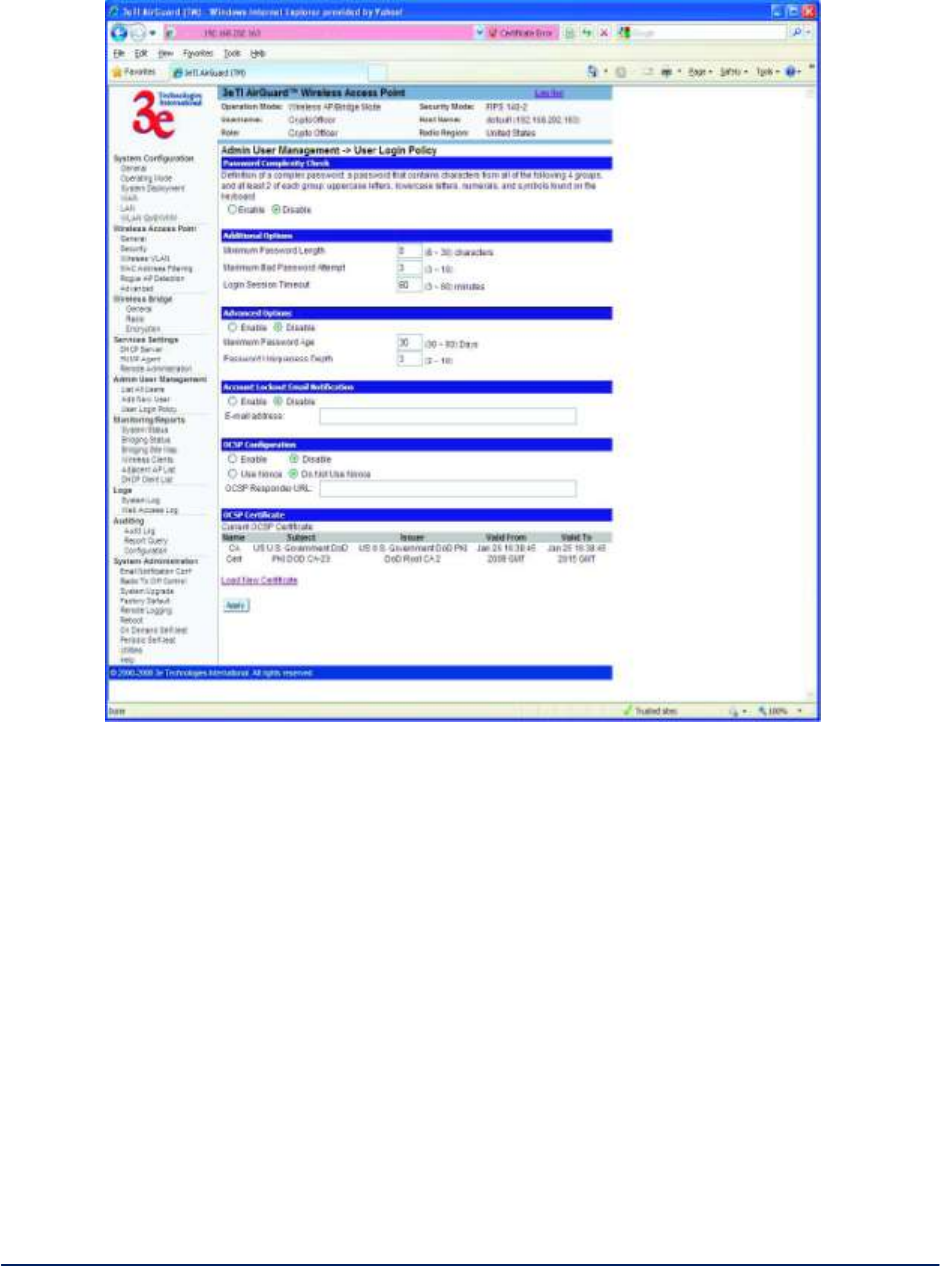
AirGuard WiMesh 3e-523 Series User’s Guide
Copyright 2015 Ultra Electronics, 3eTI
October 2015
112
29000169-005 Revision C1
Figure 102 - User Login Policy with Upload Certificate Information
Next OCSP communication to the OCSP Responder must be established. In order to enable OCSP, the
OCSP Responder URL must be entered into the Data point. This is entered in the input box under
theOCSP Configuration label, see Figure 102. OCSP supports two schemes, “http:” and “https:” The host
name may be either an IP address or domain name. The latter can only be used if DNS is able to resolve
the host name to IP address. Optionally, the port number can be specified separated from the host name
by colon.
Examples of the valid OCSP Responder URLs are:
o http://192.168.202.140
o https://192.168.202.140
o https://192.168.202.140:443
o http://3ETI-ENGR
o https://3ETI-ENGR:443
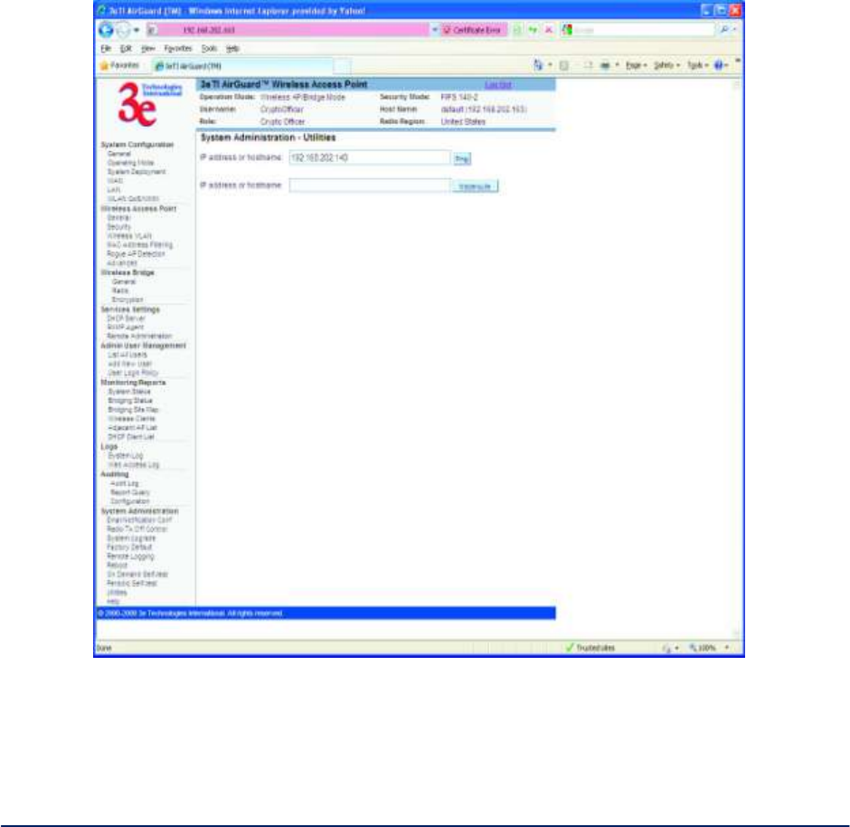
AirGuard WiMesh 3e-523 Series User’s Guide
Copyright 2015 Ultra Electronics, 3eTI
October 2015
113
29000169-005 Revision C1
IMPORTANT: Before enabling the 3eTI Data Point for OCSP communication, it is recommended
the communication with the OCSP Responder by verified. This can be done by a ping of the
OCSP Responder from the 3eTI Data Point, see Figure 103. The ping capability can be found on
the Utilities web page of the device. The IP address or host name of the OCSP Responder URL
must be entered in the IP address or hostname text box, for example, 192.168.202.140 or
3ETI-ENGR.
Click the Ping button next to the text box.
If communication between the device and OCSP Respond can be established a ping success screen as
shown in Figure 104 will be displayed.
WARNING: If the ping is not successful do not proceed until networking issues preventing successful
communication can be resolved.
Figure 103 – 3eTI Data Point Utilities Web Page
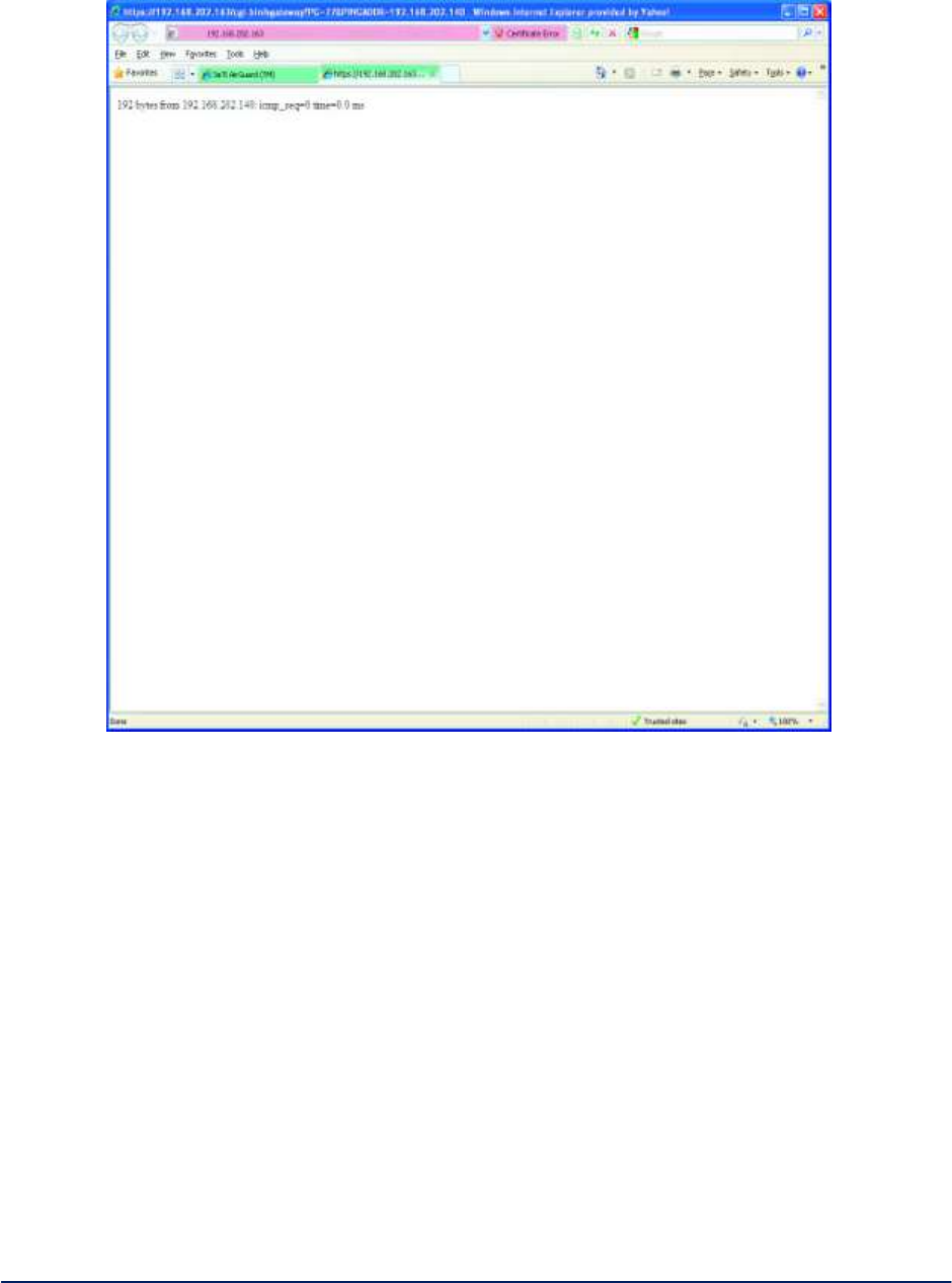
AirGuard WiMesh 3e-523 Series User’s Guide
Copyright 2015 Ultra Electronics, 3eTI
October 2015
114
29000169-005 Revision C1
Figure 104 – Ping Success Response
Once connectivity to the OCSP Responder has been verified, navigate back to User Login Policy
web page and enter OCSP Responder URL into the OCSP URL Responder text box, as shown in
Figure 105. Click the Enable radio button.
NOTE: The Use Nonce setting is optional. It should be left at Do Not Use Nonce for most installations.
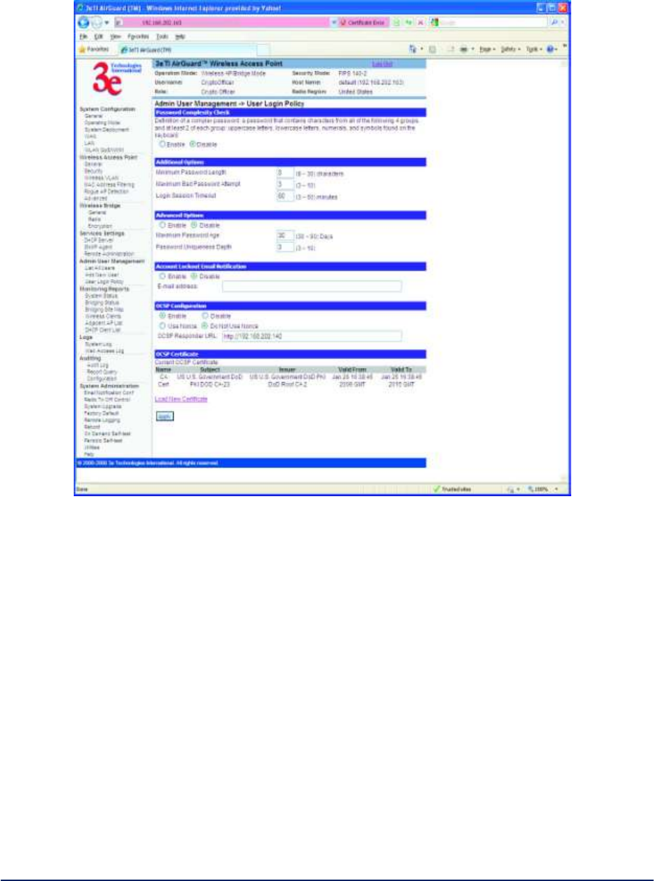
AirGuard WiMesh 3e-523 Series User’s Guide
Copyright 2015 Ultra Electronics, 3eTI
October 2015
115
29000169-005 Revision C1
Figure 105 – OCSP Responder Enable
After setting the OCSP Configuration parameters, click the Apply button at the bottom of the
screen. The a reboot required warning message will be displayed, see Figure 106.
WARNING: If the web client/AP/OCSP Responder are configured incorrectly, or there is no network
connection to the Validation Authority software / OCSP Responder, the web client will not be able to
access the device web GUI. If this occurs setting the 3eTI Data Point to its factory default configuration will
disable OCSP, allowing a user to connect to device web GUI using factory default settings.
If all enter information is correct click the OK button and navigate to the Reboot web page, click
the Reboot button. The following warning message will appear, see Figure 107.
Click the OK button. The screen shown in Figure 108 will appear.
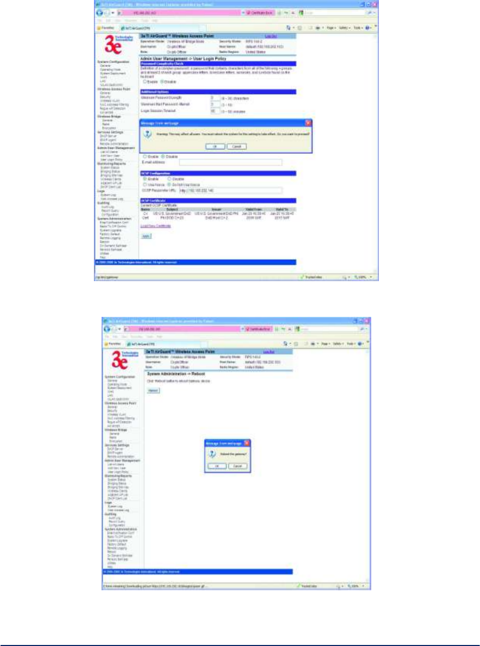
AirGuard WiMesh 3e-523 Series User’s Guide
Copyright 2015 Ultra Electronics, 3eTI
October 2015
116
29000169-005 Revision C1
Figure 106 – OCSP Enabled Warning
Figure 107 – Reboot Warning
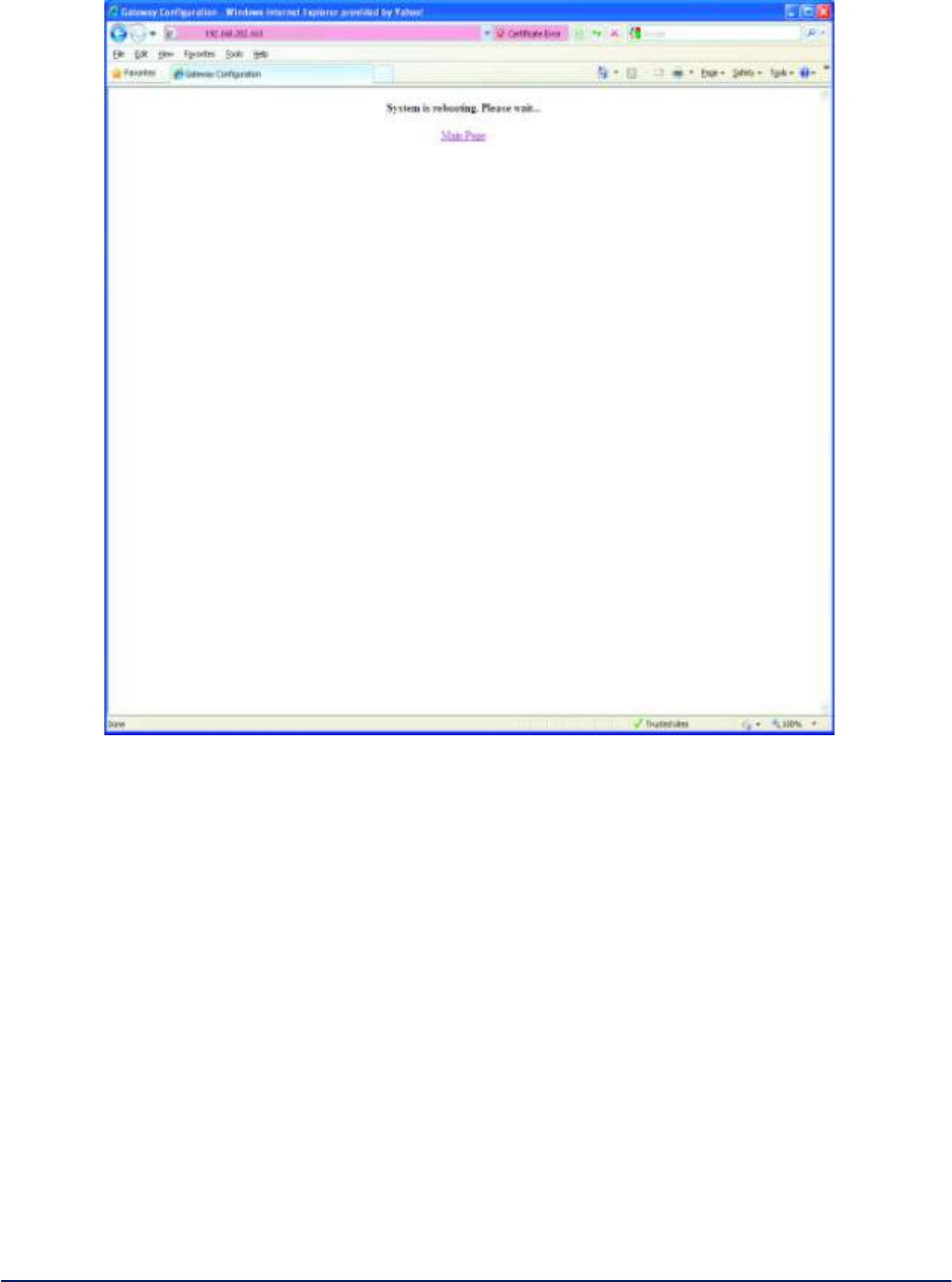
AirGuard WiMesh 3e-523 Series User’s Guide
Copyright 2015 Ultra Electronics, 3eTI
October 2015
117
29000169-005 Revision C1
Figure 108 – Reboot Success
Once the device has completed it reboot sequence, click on the Main Page link, as shown in
Figure 108.
Depending on certificate caching options, caching history, and software being used to read and validate
the CAC card, prompt(s) for validating the CAC will appear, these may be similar to those shown in as
shown in Figure 109 .
The Internet Explorer prompt for selecting the certificate to use for the connection will appear, as shown in
Figure 110.
Click on the certificate to use for accessing the device and click the OK button. A following warning
message about the web server certificate will appear, see Figure 111.
Click on the Continue to this website (not recommended) link. If a screen prompting you to add
the web-site to the exceptions list appears, add the IP address to the exceptions list. If the IP
address of this AP was previously added to the exceptions list, the following screen will appear as
in Figure 112
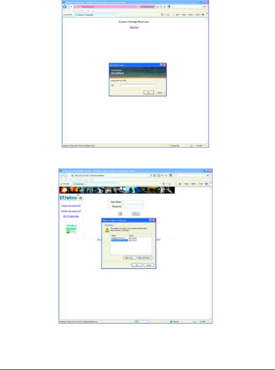
AirGuard WiMesh 3e-523 Series User’s Guide
Copyright 2015 Ultra Electronics, 3eTI
October 2015
118
29000169-005 Revision C1
Figure 109 - ActivClient Password Prompt
Figure 110 - Internet Explorer Certificate Prompt
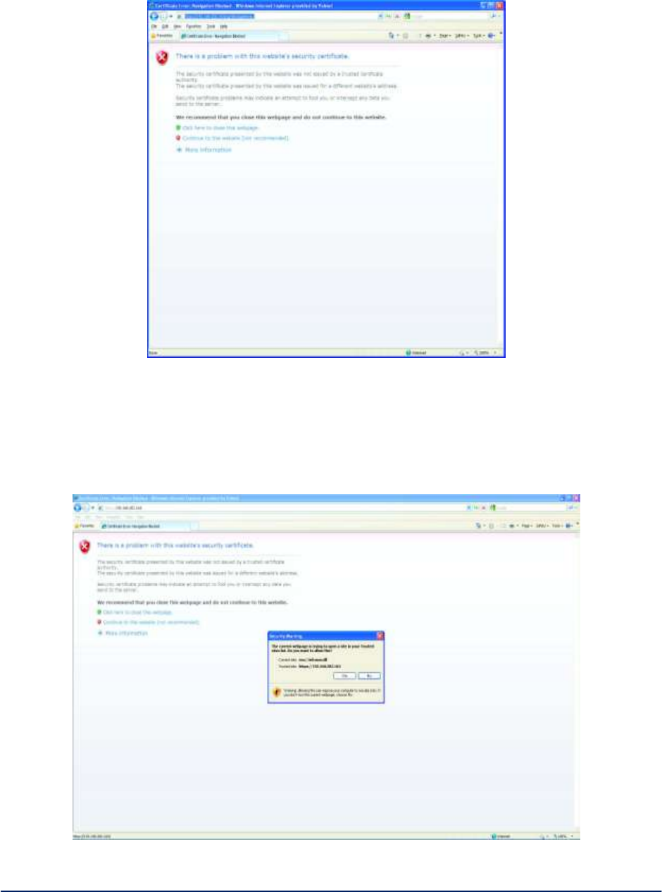
AirGuard WiMesh 3e-523 Series User’s Guide
Copyright 2015 Ultra Electronics, 3eTI
October 2015
119
29000169-005 Revision C1
Figure 111 - Internet Explorer Website Certificate Warning
Click on Yes button. The certificate list to use with this website will appear as shown in Figure
113.
Highlight the correct ID certificate and click the OK button. The login screen of the AP will appear
as in Figure 114.
Figure 112 - Internet Explorer Website Warning
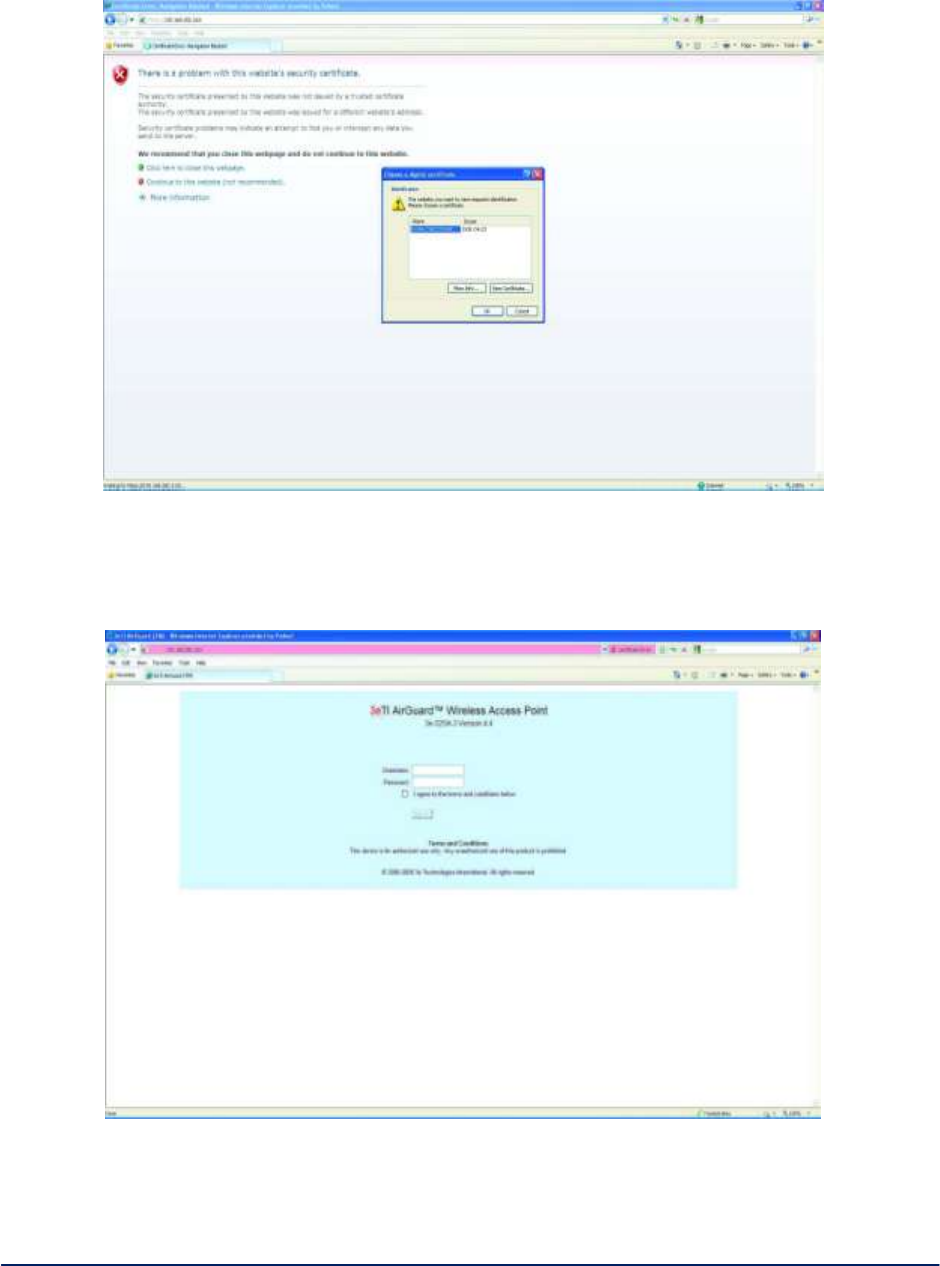
AirGuard WiMesh 3e-523 Series User’s Guide
Copyright 2015 Ultra Electronics, 3eTI
October 2015
120
29000169-005 Revision C1
Figure 113 - Internet Explorer Client Certificate List
Figure 114 - Internet Explorer Data Point Login Screen
Type the user name and password in the corresponding boxes. Click on the checkbox to accept
the Terms and Conditions, and click the Sign In button (Figure 115).
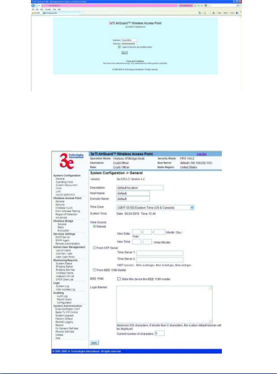
AirGuard WiMesh 3e-523 Series User’s Guide
Copyright 2015 Ultra Electronics, 3eTI
October 2015
121
29000169-005 Revision C1
Figure 115 - Internet Explorer Data Point Login Credentials
If correct login credentials were specified, the General configuration web page of the AP will appear, as
shown in Figure 116. If this screen appears the CAC certificate have been verified by the 3eTI device and
the OCSP responder. You now have access to the web GUI and can configure and manage the device.
Figure 116 - Internet Explorer Data Point General Configuration Web Page
B.3 Optional 3rd party Device Configuration Overview
AirGuard WiMesh 3e-523 Series User’s Guide
Copyright 2015 Ultra Electronics, 3eTI
October 2015
122
29000169-005 Revision C1
3eTI has tested and validated the above capabilities using ActivIdentity ActivClient and Tumbleweed
Valicert Validation Authority software providing an end to end validation capability. It is recognized that
other OCSP based software may provide the same capabilities. This section is intended to provide an
overview of configuring the above software for use within a PKI network. More detail on how to use and
configure the software can be found in the respective user manuals for each product.
Configuration Procedure Web Client Configuration
Install the ActiveIdentity ActiveClient software as specified by the vendor
Obtain a valid CAC card (3eTI has validated this feature using a DoD CA-23 issued CAC).
Insert the CAC card into the smart card slot of the PC.
Once the ActivClient software recognizes the CAC, double click on ActivClient icon in the System
Tray to open the software window, shown in and navigate to Tools -> Advanced -> Make
Certificates Available to Windows, as shown in Figure 117
Figure 117 - ActivClient Certificate Export
Open Internet Explorer. Click on menu item Tools -> Internet Options. Click on Advanced tab
and scroll down to SSL/TLS options. Make sure that Use SSL 2.0 and Use SSL 3.0 options are
unchecked and Use TLS 1.0 option is checked, as shown in Figure 118.
The software is ready to be used, please refer to the appropriate software configuration documentation to
insure proper setup and operation.
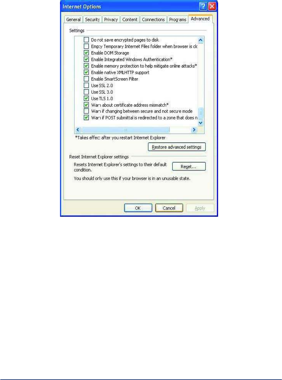
AirGuard WiMesh 3e-523 Series User’s Guide
Copyright 2015 Ultra Electronics, 3eTI
October 2015
123
29000169-005 Revision C1
Figure 118 - Internet Explorer Security Options
OCSP Responder Configuration
Install the Tumbleweed Valicert Validation Authority software as specified by the vendor
Appropriate certificate and corresponding CRL available as described in previous sections (3eTI
has tested the configuration using DoD CA-23 issued CAC)
Open web GUI to the OCSP Responder and navigate to the CONFIGURATION -> Keys and
Certificates -> Certificates page. Verify that the certificate (CAC issuer certificate) is installed.
This is the same certificate that will be installed on the 3eTI Data Point.
If the certificate is not installed, click the Add button and load the certificate from the local file. This
is shown in the Figure 119.
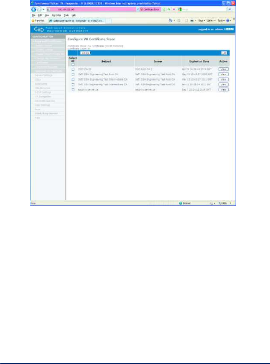
AirGuard WiMesh 3e-523 Series User’s Guide
Copyright 2015 Ultra Electronics, 3eTI
October 2015
124
29000169-005 Revision C1
Figure 119 - OCSP Responder Certificates
Navigate to the CONFIGURATION -> CRLs -> Upload Crl screen and upload the correct
certificate from the local file.
Navigate to CONFIGURATION -> CRLs and OCSP Databases and verify that the certificate is
listed as shown in Figure 120.
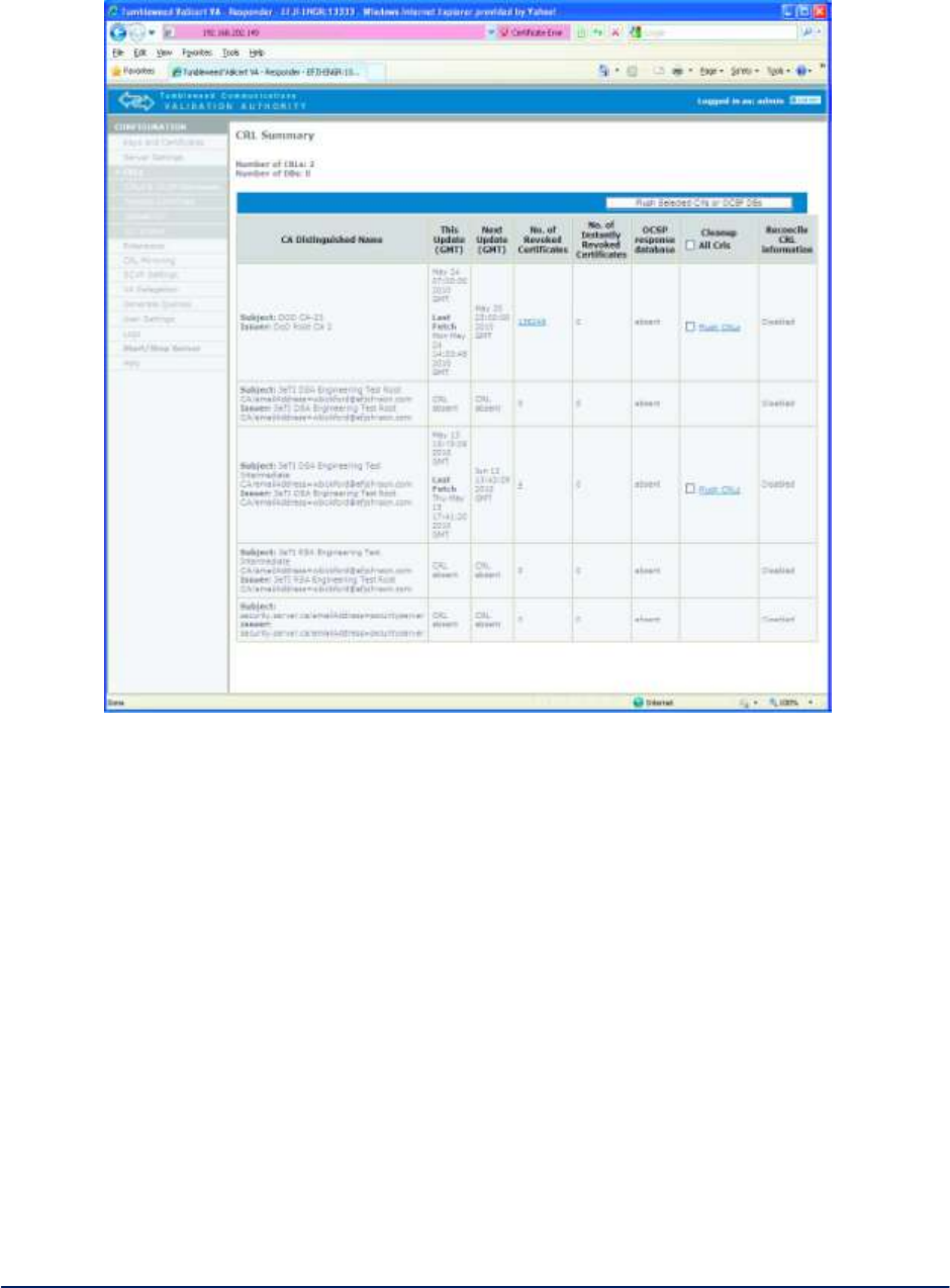
AirGuard WiMesh 3e-523 Series User’s Guide
Copyright 2015 Ultra Electronics, 3eTI
October 2015
125
29000169-005 Revision C1
Figure 120 - OCSP Responder CRLs

AirGuard WiMesh 3e-523 Series User’s Guide
Copyright 2015 Ultra Electronics, 3eTI
October 2015
126
29000169-005 Revision C1
Appendix C: Common Criteria Supplement
If the 3e-525A-3 product family is to be operated in a Common Criteria certified environment, the product
MUST be inspected upon arrival from 3e Technologies International. If the any of the red tamper-evident
tapes indicate that the product or its CDROM sleeve have been opened, the user is not to use the product
prior to contacting 3eTechnologies International:
Ultra Electronics, 3eTI
9713 Key West Avenue
Suite 500
Rockville, Maryland 20850 USA
Telephone: 1-800-449-3384
FAX: 1-301-670-6989
Once the product is in the user’s possession, it is the responsibility of the user to use and maintain the
product and its CDROM in a safe and secure manner as defined within this document. If the user finds any
issues of the product and deems that is security related, the user shall contact 3eTI at the address above.
In order to operate the 3e-525A-3 product in a Common Criteria certified environment, the following MUST
be carried out.
1. On the System Configuration Operating Mode GUI screen:
[FIPS 140-2 Mode] MUST be selected
2. The Administrator’s session timeout must be set to a minimum of 10 minutes.
To operate in the Common Criteria environment, the Crypto-Officer and Administrators must enforce the
following password policy. That is, all passwords required in the use of the 3e-525A-3 product must:
have a minimum length of 8 characters,
contain at least two uppercase characters (A, B, C, …) and two
lowercase characters (a, b, c, …),
contain at least two numeric characters (1, 2, 3, …),
contain at least two special characters,
have a 30 day expiration date,
not be a common word, a word in any existing password dictionaries, or a word easily guessed
(such as “password”).
To operate in the Common Criteria environment, all Crypto-Officers and Administrators responsible for the
3e-525A-3 product must be non-hostile and appropriately trained, and must follow all of the guidance
information contained in this document.
To operate in the Common Criteria environment, the 3e-525A-3 product (plus associated clients and the
3e-030-2 as appropriate) shall be installed with appropriate physical security, commensurate with the
value of the products and the data contained within.
CryptoOfficer and Administrator have different privileges in managing the device, the table below shows
the user-accessible functions and privilege all security parameters under the control of the user, indicating
secure values as appropriate each type of security-relevant event relative to the user-accessible functions
that need to be performed.
AirGuard WiMesh 3e-523 Series User’s Guide
Copyright 2015 Ultra Electronics, 3eTI
October 2015
127
29000169-005 Revision C1
Categories
Features
Operators
Parameters
Audit Events
Crypto Officer
Administrator
Show1
Set2
Add3
Delete4
Show5
Set6
Add7
Delete8
System
Configuration
Operating
Mode
AP / Bridging Mode –
FIPS
AP / Bridging Mode –
Non-FIPS
X
X
X
X
X
X
X
FIPS/Non-FI
PS mode
None
Wireless Access
Point
Security
AES (128-/192-256-bit)
X
X
AES 128
key:
32 hex
digits
AES 192
key:
48 hex
digits
AES 256:
64 hex
digits
EVT_KEY_GENERATED
EVT_KEY_ZEROIZED
EVT_ENCRYPT_ALG_CHANGED
EVT_STA_ASSOC
EVT_SELF_TEST_ACTIVATED
FIPS 802.11i
X
X
Pre-Shared
EVT_KEY_GENERATED
EVT_KEY_ZEROIZED
1 The operator can view this setting
2 The operator can change this setting
3 The operator can add a required input. For example: Adding an entry to the MAC address filtering table
4 The operator can delete a particular entry. For example: Deleting an entry from the MAC address filtering table
5 The operator can view this setting
6 The operator can change this setting
7 The operator can add a required input. For example: Adding an entry to the MAC address filtering table
8 The operator can delete a particular entry. For example: Deleting an entry from the MAC address filtering table
AirGuard WiMesh 3e-523 Series User’s Guide
Copyright 2015 Ultra Electronics, 3eTI
October 2015
128
29000169-005 Revision C1
Categories
Features
Operators
Parameters
Audit Events
Crypto Officer
Administrator
Show1
Set2
Add3
Delete4
Show5
Set6
Add7
Delete8
key:
64 hex
digits
Radius
Server IP:
valid
IPV4
address
Shared
secret:
10 to 95
characters
Backend
password:
10 to 95
characters
Backend
key:
10 to 95
characters
EVT_ENCRYPT_ALG_CHANGED
EVT_STA_ASSOC
EVT_SELF_TEST_ACTIVATED
Wireless Bridge
Encryption
AES (128-/192-256-bit)
X
X
AES 128
key:
32 hex
digits
AES 192
key:
48 hex
digits
AES 256:
64 hex
digits
EVT_KEY_GENERATED
EVT_KEY_ZEROIZED
EVT_ENCRYPT_ALG_CHANGED
EVT_STA_ASSOC
EVT_SELF_TEST_ACTIVATED
AES_CCMP
X
X
X
32 hex digits
EVT_KEY_GENERATED
EVT_KEY_ZEROIZED
EVT_ENCRYPT_ALG_CHANGED
EVT_STA_ASSOC
AirGuard WiMesh 3e-523 Series User’s Guide
Copyright 2015 Ultra Electronics, 3eTI
October 2015
129
29000169-005 Revision C1
Categories
Features
Operators
Parameters
Audit Events
Crypto Officer
Administrator
Show1
Set2
Add3
Delete4
Show5
Set6
Add7
Delete8
EVT_SELF_TEST_ACTIVATED
Service Settings
SNMP agent
Enable/ Disable
Community settings
Secure User
Configuration
System Information
X
X
X
X
X
X
X
X
X
X
X
X
X
X
X
X
None
None
User Management
List All Users
X
X
X
X
None
None
Add New User
X
None
EVT_USER_AUTH_INFO
User
Password
Policy
Enable/Disable
Policy setting
X
X
X
X
passwd
complexity
enable/disa
ble
min passwd
length:
8 to 30
characters
max bad
passwd
entries
3 to 10
session
timeout
3 to 60
minutes
max passwd
age
30 to 90
days
uniqueness
EVT_USER_AUTH_INFO

AirGuard WiMesh 3e-523 Series User’s Guide
Copyright 2015 Ultra Electronics, 3eTI
October 2015
130
29000169-005 Revision C1
Categories
Features
Operators
Parameters
Audit Events
Crypto Officer
Administrator
Show1
Set2
Add3
Delete4
Show5
Set6
Add7
Delete8
depth
3 to 10
characters
OSCP
enable/disa
ble
Monitoring /
Reports
System Log
Date/Time/Message
X
X
X
X
None
None
Web Access
Log
X
X
X
X
None
None
Auditing
Log
X
X
None
None
Report Query
X
X
None
None
Configuration
Enable/Disable
Selectable items
X
X
X
X
None
EVT_AUDIT_CFG_MOD
System
Administration
System
Upgrade
Firmware Upgrade
Local Configuration
Upgrade
Remote Configuration
Upgrade
X
X
X
X
X
X
None
None
Self Tests
Perform Cryptographic
algorithm KAT, key error
detection test, software
integrity check
X
X
None
EVT_SELF_TEST_ACTIVATED
Factory
Defaults
X
None
None
Remote
Logging
Enable/Disable
X
X
X
X
None
EVT_AUDIT_LOG_STATE_CHAN
AirGuard WiMesh 3e-523 Series User’s Guide
Copyright 2015 Ultra Electronics, 3eTI
October 2015
131
29000169-005 Revision C1
Categories
Features
Operators
Parameters
Audit Events
Crypto Officer
Administrator
Show1
Set2
Add3
Delete4
Show5
Set6
Add7
Delete8
Settings
X
X
X
X
GED
Reboot
X
X
X
None
None