4RF SQ757M160 Digital Transceiver User Manual Part 1 of 3
4RF Limited Digital Transceiver Part 1 of 3
4RF >
Contents
- 1. User Manual - Part 1 of 3
- 2. User Manual - Part 2 of 3
- 3. User Manual - Part 3 of 3
User Manual - Part 1 of 3
July 2016
Version 1.6.0

| 1
Aprisa SR+ User Manual 1.6.0 PO
Copyright
Copyright © 2016 4RF Limited. All rights reserved.
This document is protected by copyright belonging to 4RF Limited and may not be reproduced or
republished in whole or part in any form without the prior written permission of 4RF Limited.
Trademarks
Aprisa and the 4RF logo are trademarks of 4RF Limited.
Windows is a registered trademark of Microsoft Corporation in the United States and other countries. Java
and all Java-related trademarks are trademarks or registered trademarks of Sun Microsystems, Inc. in the
United States and other countries. All other marks are the property of their respective owners.
Disclaimer
Although every precaution has been taken preparing this information, 4RF Limited assumes no liability for
errors and omissions, or any damages resulting from use of this information. This document or the
equipment may change, without notice, in the interests of improving the product.
RoHS and WEEE Compliance
The Aprisa SR+ is fully compliant with the European Commission’s RoHS (Restriction of Certain Hazardous
Substances in Electrical and Electronic Equipment) and WEEE (Waste Electrical and Electronic Equipment)
environmental directives.
Restriction of hazardous substances (RoHS)
The RoHS Directive prohibits the sale in the European Union of electronic equipment containing these
hazardous substances: lead, cadmium, mercury, hexavalent chromium, polybrominated biphenyls (PBBs),
and polybrominated diphenyl ethers (PBDEs).
4RF has worked with its component suppliers to ensure compliance with the RoHS Directive which came
into effect on the 1st July 2006.
End-of-life recycling programme (WEEE)
The WEEE Directive concerns the recovery, reuse, and recycling of electronic and electrical equipment.
Under the Directive, used equipment must be marked, collected separately, and disposed of properly.
4RF has instigated a programme to manage the reuse, recycling, and recovery of waste in an
environmentally safe manner using processes that comply with the WEEE Directive (EU Waste Electrical
and Electronic Equipment 2002/96/EC).
4RF invites questions from customers and partners on its environmental programmes and compliance with
the European Commission’s Directives (sales@4RF.com).
2 |
Aprisa SR+ User Manual 1.6.0 PO
Compliance General
The Aprisa SR+ radio predominantly operates within frequency bands that require a site license be issued
by the radio regulatory authority with jurisdiction over the territory in which the equipment is being
operated.
It is the responsibility of the user, before operating the equipment, to ensure that where required the
appropriate license has been granted and all conditions attendant to that license have been met.
Changes or modifications not approved by the party responsible for compliance could void the user’s
authority to operate the equipment.
Equipment authorizations sought by 4RF are based on the Aprisa SR+ radio equipment being installed at a
fixed restricted access location and operated in point-to-multipoint or point-to-point mode within the
environmental profile defined by EN 300 019, Class 3.4. Operation outside these criteria may invalidate
the authorizations and / or license conditions.
The term ‘Radio’ with reference to the Aprisa SR+ User Manual, is a generic term for one end station of a
point-to-multipoint Aprisa SR+ network and does not confer any rights to connect to any public network or
to operate the equipment within any territory.
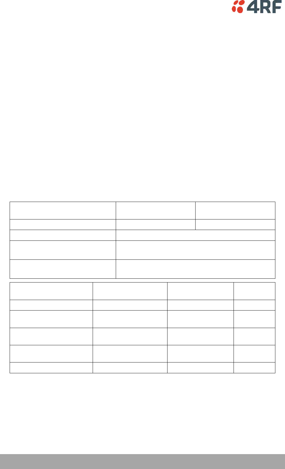
Compliance European Telecommunications Standards Institute
The Aprisa SR+ radio is designed to comply with the European Telecommunications Standards Institute
(ETSI) specifications as follows:
12.5 kHz and 25 kHz
Channel
50 kHz Channel
Radio performance
EN 300 113-2
EN 302 561 (pending)
EMC
EN 301 489-1 and 5
Environmental
EN 300 019, Class 3.4
Ingress Protection IP51
Safety
EN 60950-1:2006
Class 1 division 2 for hazardous locations
Frequency band
Channel size
Power input
Notified
body
135-175 MHz
12.5 kHz, 25 kHz
13.8 VDC
215-240 MHz
12.5 kHz, 20 kHz,
25 kHz, 50 kHz
13.8 VDC
320-400 MHz
12.5 kHz, 20 kHz,
25 kHz, 50 kHz
13.8 VDC
400-470 MHz
12.5 kHz, 20 kHz,
25 kHz, 50 kHz
13.8 VDC
450-520 MHz
12.5 kHz, 25 kHz, 50 kHz
13.8 VDC
| 3
Aprisa SR+ User Manual 1.6.0 PO
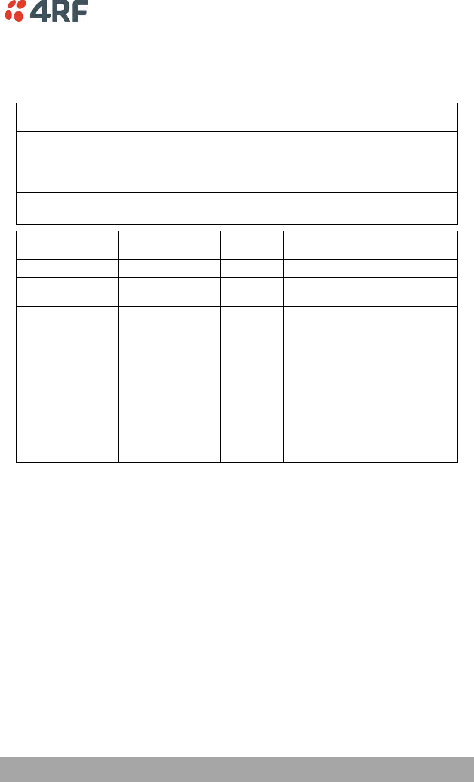
Compliance Federal Communications Commission
The Aprisa SR+ radio is designed to comply with the Federal Communications Commission (FCC)
specifications as follows:
Radio
47CFR part 24, part 27, part 90 and part 101 Private Land
Mobile Radio Services
EMC
47CFR part 15 Radio Frequency Devices, EN 301 489-1 and
5
Environmental
EN 300 019, Class 3.4
Ingress Protection IP51
Safety
EN 60950-1:2006
Class 1 division 2 for hazardous locations
Frequency Band *
Channel size
Power
input
Authorization
FCC ID
135-175 MHz
15 kHz, 30 kHz
13.8 VDC
Part 90
UIPSQ135M150
215-240 MHz
12.5 kHz, 15 kHz,
25 kHz, 50 kHz
13.8 VDC
Part 90
UIPSQ215M141
400-470 MHz
12.5 kHz, 25 kHz,
50 kHz
13.8 VDC
Part 90
UIPSQ400M1311
450-520 MHz
12.5 kHz, 25 kHz
13.8 VDC
Part 90
Pending
896-902 MHz
12.5 kHz, 25 kHz,
50 kHz
13.8 VDC
Part 24 /
Part 90 /
Part 101
UIPSQ896M141
928-960 MHz
12.5 kHz, 25 kHz,
50 kHz
13.8 VDC
Part 24 /
Part 90 /
Part 101
UIPSQ928M141
NOTE: This equipment has been tested and found to comply with the limits for a Class A digital device,
pursuant to part 15 of the FCC Rules. These limits are designed to provide reasonable protection against
harmful interference when the equipment is operated in a commercial environment. This equipment
generates, uses, and can radiate radio frequency energy and, if not installed and used in accordance with
the instruction manual, may cause harmful interference to radio communications. Operation of this
equipment in a residential area is likely to cause harmful interference in which case the user will be
required to correct the interference at his own expense.
* The Frequency Band is not an indication of the exact frequencies approved by FCC.
787-788 MHz
50
kHz
757-758 MHz and
1
2
.
5 kHz,
25
kHz,
13.8 VDC
Part 27
Pending
4 |
Aprisa SR+ User Manual 1.6.0 PO
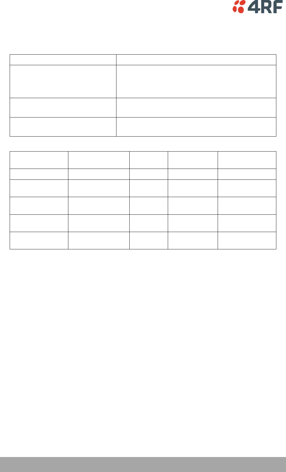
Compliance Industry Canada
The Aprisa SR+ radio is designed to comply with Industry Canada (IC) specifications as follows:
Radio
RSS-119 / RSS-134
EMC
This Class A digital apparatus complies with Canadian
standard ICES-003.
Cet appareil numérique de la classe A est conforme à la
norme NMB-003 du Canada.
Environmental
EN 300 019, Class 3.4
Ingress Protection IP51
Safety
EN 60950-1:2006
Class 1 division 2 for hazardous locations
Frequency Band *
Channel size
Power
input
Authorization
IC
135-175 MHz
15 kHz, 30 kHz
13.8 VDC
RSS-119
6772A-SQ135M150
215-240 MHz
12.5 kHz, 15 kHz,
25 kHz, 50 kHz
13.8 VDC
RSS-119
Pending
400-470 MHz
12.5 kHz, 25 kHz,
50 kHz
13.8 VDC
RSS-119
6772A-SQ400M1311
896-902 MHz
12.5 kHz, 25 kHz,
50 kHz
13.8 VDC
RSS-119 and
RSS-134
Pending
928-960 MHz
12.5 kHz, 25 kHz,
50 kHz
13.8 VDC
RSS-119 and
RSS-134
Pending
* The Frequency Band is not an indication of the exact frequencies approved by IC.
Compliance Brazil
Este produto será comercializado no Brasil com as configurações abaixo:
Faixa de frequência: 406,10 a 413,05, 423,05 a 430 MHz, 451,00625 a 452,0065 MHz, 459 a 460 MHz,
461,0025 a 462,00625 MHz e 469 a 470 MHz.
Modulações: QPSK, 16QAM e 64QAM
BW: 12,5 e 25 KHz.

| 5
Aprisa SR+ User Manual 1.6.0 PO
Compliance Hazardous Locations Notice
This product is suitable for use in Class 1, Division 2, Groups A - D hazardous locations or non-hazardous
locations.
The following text is printed on the Aprisa SR+ fascia:
WARNING: EXPLOSION HAZARD - Do not connect or disconnect while circuits are live unless area is known
to be non-hazardous.
The following text is printed on the Aprisa SR+ where the end user is in Canada:
AVERTISSEMENT: RISQUE D'EXPLOSION - Ne pas brancher ou débrancher tant que le circuit est sous
tension, à moins qu'il ne s'agisse d'un emplacement non dangereux.
The USB service ports are not to be used unless the area is known to be non-hazardous.
Compliance IEEE 1613 class 2
Users requiring compliance to IEEE 1613 class 2 should use screened cables and connectors to connect to
the serial ports.
6 |
Aprisa SR+ User Manual 1.6.0 PO
RF Exposure Warning
WARNING:
The installer and / or user of Aprisa SR+ radios shall ensure that a separation distance
as given in the following table is maintained between the main axis of the terminal’s
antenna and the body of the user or nearby persons.
Minimum separation distances given are based on the maximum values of the
following methodologies:
1. Maximum Permissible Exposure non-occupational limit (B or general public) of
47 CFR 1.1310 and the methodology of FCC’s OST/OET Bulletin number 65.
2. Reference levels as given in Annex III, European Directive on the limitation of
exposure of the general public to electromagnetic fields (0 Hz to 300 GHz)
(1999/519/EC). These distances will ensure indirect compliance with the
requirements of EN 50385:2002.
Frequency (MHz)
Maximum Power
(dBm) Note 1
Maximum Antenna
Gain (dBi)
Minimum Separation
Distance
(m)
135
+ 37
15
3.5
175
+ 37
15
3.5
215
+ 37
15
3.5
240
+ 37
15
3.5
320
+ 37
15
3.5
400
+ 37
15
3.0
450
+ 37
15
3.0
470
+ 37
15
3.0
520
+ 37
15
3.0
757
+ 37
18
3.5
788
+ 37
18
3.5
896
+ 37
28
10.0
902
+ 37
28
10.0
928
+ 37
28
9.5
960
+ 37
28
9.5
Note 1: The Peak Envelope Power (PEP) at maximum set power level is +41 dBm.

Contents | 7
Aprisa SR+ User Manual 1.6.0 PO
Contents
1. Getting Started ........................................................................ 13
2. Introduction ............................................................................ 15
About This Manual ............................................................................... 15
What It Covers ............................................................................ 15
Who Should Read It ...................................................................... 15
Contact Us ................................................................................. 15
What’s in the Box ............................................................................... 15
Aprisa SR+ Accessory Kit ................................................................ 16
Aprisa SR+ CD Contents .................................................................. 16
Software ............................................................................ 16
Documentation .................................................................... 16
3. About the Radio ....................................................................... 17
The 4RF Aprisa SR+ Radio ...................................................................... 17
Product Overview ............................................................................... 18
Network Coverage and Capacity ....................................................... 18
Automatic Registration .................................................................. 18
Remote Messaging ........................................................................ 18
Store and Forward Repeater ............................................................ 19
Repeater Packet Forwarding..................................................... 19
Repeater Messaging ............................................................... 22
Peer To Peer Communication Between Remote Radios ...................... 23
Product Features ................................................................................ 24
Functions .................................................................................. 24
Security .................................................................................... 25
Performance .............................................................................. 26
Usability ................................................................................... 26
System Gain vs FEC Coding ............................................................. 27
Architecture ...................................................................................... 28
Product Operation ........................................................................ 28
Physical Layer ............................................................................. 28
Data Link Layer / MAC layer ............................................................ 29
Channel Access .................................................................... 29
Hop by Hop Transmission ......................................................... 30
Adaptive Coding and Modulation ................................................ 30
Network Layer ............................................................................ 31
Packet Routing ..................................................................... 31
Static IP Router .................................................................... 32
Bridge Mode with VLAN Aware .................................................. 35
VLAN Bridge Mode Description .................................................. 36
Avoiding Narrow Band Radio Traffic Overloading .................................... 38
Interfaces ......................................................................................... 40
Antenna Interface ........................................................................ 40
Ethernet Interface ....................................................................... 40
RS-232 / RS-485 Interface ............................................................... 40
USB Interfaces ............................................................................ 40
Protect Interface ......................................................................... 40
Alarms Interface .......................................................................... 40

8 | Contents
Aprisa SR+ User Manual 1.6.0 PO
Front Panel Connections ....................................................................... 41
LED Display Panel ............................................................................... 42
Normal Operation ........................................................................ 42
Single Radio Software Upgrade ......................................................... 43
Network Software Upgrade ............................................................. 43
Test Mode ................................................................................. 44
Network Management .......................................................................... 45
Hardware Alarm Inputs / Outputs ............................................................ 46
Alarm Input to SNMP Trap ............................................................... 46
Alarm Input to Alarm Output ........................................................... 46
Aprisa SR Alarm Input to Aprisa SR+ Alarm Output .................................. 46
4. Implementing the Network.......................................................... 47
Network Topologies ............................................................................. 47
Point-To-Point Network .......................................................... 47
Point-to-Multipoint Network ..................................................... 47
Point-to-Multipoint with Repeater 1 ............................................ 47
Point-to-Multipoint with Repeater 2 ............................................ 47
Initial Network Deployment ................................................................... 48
Install the Base Station .................................................................. 48
Installing the Remote Stations ......................................................... 48
Install a Repeater Station ............................................................... 48
Network Changes ................................................................................ 49
Adding a Repeater Station .............................................................. 49
Adding a Remote Station ................................................................ 49
5. Preparation ............................................................................ 51
Bench Setup ...................................................................................... 51
Path Planning .................................................................................... 52
Antenna Selection and Siting ........................................................... 52
Base or Repeater Station ......................................................... 52
Remote station .................................................................... 53
Antenna Siting ..................................................................... 54
Coaxial Feeder Cables ................................................................... 55
Linking System Plan ...................................................................... 55
Site Requirements ............................................................................... 56
Power Supply .............................................................................. 56
Equipment Cooling ....................................................................... 56
Earthing and Lightning Protection ..................................................... 57
Feeder Earthing .................................................................... 57
Radio Earthing ..................................................................... 57
6. Installing the Radio ................................................................... 58
Mounting .......................................................................................... 58
Required Tools ............................................................................ 58
DIN Rail Mounting ........................................................................ 59
Rack Shelf Mounting ..................................................................... 60
Wall Mounting ............................................................................. 61
Installing the Antenna and Feeder Cable .................................................... 62
Connecting the Power Supply ................................................................. 63
External Power Supplies ................................................................. 63
Spare Fuses ................................................................................ 64
Additional Spare Fuses ............................................................ 65

Contents | 9
Aprisa SR+ User Manual 1.6.0 PO
7. Managing the Radio ................................................................... 67
SuperVisor ........................................................................................ 67
PC Requirements for SuperVisor ....................................................... 68
Connecting to SuperVisor ............................................................... 69
Management PC Connection ..................................................... 70
PC Settings for SuperVisor ....................................................... 71
Login to SuperVisor................................................................ 75
Logout of SuperVisor .............................................................. 76
SuperVisor Page Layout ........................................................... 77
SuperVisor Menu ................................................................... 79
SuperVisor Menu Access .......................................................... 80
SuperVisor Menu Items ........................................................... 82
Standard Radio............................................................................ 83
Terminal ............................................................................ 83
Radio .............................................................................. 101
Serial .............................................................................. 122
Ethernet .......................................................................... 137
IP................................................................................... 147
QoS ................................................................................ 160
Security ........................................................................... 182
Maintenance ..................................................................... 204
Events ............................................................................. 222
Software .......................................................................... 234
Monitoring ........................................................................ 253
Network Status .................................................................. 271
Protected Station ...................................................................... 278
Terminal .......................................................................... 279
Radio .............................................................................. 285
Ethernet .......................................................................... 287
IP................................................................................... 288
Security ........................................................................... 292
Maintenance ..................................................................... 294
Events ............................................................................. 302
Software .......................................................................... 305
Command Line Interface ..................................................................... 322
Connecting to the Management Port ................................................ 322
CLI Commands .......................................................................... 325
Viewing the CLI Terminal Summary ........................................... 326
Changing the Radio IP Address with the CLI ................................. 326
8. In-Service Commissioning .......................................................... 327
Before You Start ............................................................................... 327
What You Will Need .................................................................... 327
Antenna Alignment ............................................................................ 328
Aligning the Antennas ................................................................. 328

10 | Contents
Aprisa SR+ User Manual 1.6.0 PO
9. Product Options ...................................................................... 329
Data Interface Ports .......................................................................... 329
Full Duplex Base Station ..................................................................... 329
Protected Station ............................................................................. 330
Protected Ports ......................................................................... 331
Operation ................................................................................ 331
Switch Over ...................................................................... 331
Switching Criteria ............................................................... 332
Monitored Alarms ................................................................ 333
Configuration Management .................................................... 334
Hardware Manual Lock ......................................................... 335
Remote Control .................................................................. 335
L2 / L3 Protection Operation .................................................. 336
Hot-Swappable ................................................................... 336
Antenna and Duplexer Options ................................................ 337
Installation .............................................................................. 339
Mounting .......................................................................... 339
Cabling ............................................................................ 340
Power ............................................................................. 342
Alarms ............................................................................. 342
Maintenance ............................................................................ 343
Changing the Protected Station IP Addresses ............................... 343
Creating a Protected Station .................................................. 344
Replacing a Protected Station Faulty Radio ................................. 344
Replacing a Faulty Power Supply .............................................. 345
Replacing a Faulty Protection Switch ........................................ 345
Spares .................................................................................... 345
Data Driven Protected Station............................................................... 346
Operation ................................................................................ 346
Over The Air Compatibility .................................................... 346
Switch Over ...................................................................... 347
Configuration Management .................................................... 347
Power ............................................................................. 347
Installation .............................................................................. 348
Mounting .......................................................................... 348
Cabling ............................................................................ 348
Duplexer Kits ................................................................................... 349
Radio Duplexer Kits .................................................................... 349
Protected Station Duplexer Kits ...................................................... 351
USB RS-232 / RS-485 Serial Port ............................................................. 353
USB RS-232 / RS-485 operation ....................................................... 353
USB RS-232 Cabling Options ........................................................... 354
USB RS-485 Cabling Options ........................................................... 354
USB Retention Clip .............................................................. 355

Contents | 11
Aprisa SR+ User Manual 1.6.0 PO
10. Maintenance .......................................................................... 357
No User-Serviceable Components ........................................................... 357
Software Upgrade ............................................................................. 358
Network Software Upgrade ........................................................... 358
Non-Protected Network Upgrade Process .................................... 358
Protected Network Upgrade Process ......................................... 360
Single Radio Software Upgrade ....................................................... 362
File Transfer Method ............................................................ 362
USB Boot Upgrade Method ..................................................... 363
Software Downgrade ............................................................ 363
Protected Station Software Upgrade ................................................ 364
11. Interface Connections ............................................................... 365
RJ45 Connector Pin Assignments ............................................................ 365
Ethernet Interface Connections ............................................................. 365
RS-232 Serial Interface Connections ........................................................ 366
RS-232 Pinout .................................................................... 366
RS-232 Customer Cable Wiring ................................................ 366
RS-232 RJ45 LED Indicators .................................................... 366
Alarm Interface Connections ................................................................ 367
Protection Switch Remote Control Connections .......................................... 367
12. Alarm Types and Sources ........................................................... 368
Alarm Types .................................................................................... 368
Alarm Events ............................................................................ 369
Informational Events ................................................................... 374
13. Specifications ......................................................................... 375
RF Specifications .............................................................................. 375
Frequency Bands ....................................................................... 375
Channel Sizes ........................................................................... 376
Receiver ................................................................................. 389
Transmitter ............................................................................. 392
Modem ................................................................................... 393
Data Payload Security ................................................................. 393
Interface Specifications ...................................................................... 394
Ethernet Interface ..................................................................... 394
RS-232 Asynchronous Interface ....................................................... 395
Hardware Alarms Interface ........................................................... 396
Protection Switch Specifications ..................................................... 396
Power Specifications .......................................................................... 397
Power Supply ............................................................................ 397
Power Consumption .................................................................... 398
Power Dissipation ...................................................................... 398
General Specifications ........................................................................ 399
Environmental .......................................................................... 399
Mechanical .............................................................................. 399
Compliance .............................................................................. 400

12 | Contents
Aprisa SR+ User Manual 1.6.0 PO
14. Product End Of Life .................................................................. 401
End-of-Life Recycling Programme (WEEE) ................................................. 401
The WEEE Symbol Explained .......................................................... 401
WEEE Must Be Collected Separately ................................................. 401
YOUR ROLE in the Recovery of WEEE ................................................ 401
EEE Waste Impacts the Environment and Health .................................. 401
15. Copyrights ............................................................................. 402
16. Abbreviations ......................................................................... 403

Getting Started | 13
Aprisa SR+ User Manual 1.6.0 PO
1. Getting Started
This section is an overview of the steps required to commission an Aprisa SR+ radio network in the field:
Phase 1:
Pre-installation
1.
Confirm path planning.
Page 52
2.
Ensure that the site preparation is complete:
Power requirements
Tower requirements
Environmental considerations, for example, temperature control
Mounting space
Page 55
Phase 2:
Installing the radios
1.
Mount the radio.
Page 58
2.
Connect earthing to the radio.
Page 57
3.
Confirm that the:
Antenna is mounted and visually aligned
Feeder cable is connected to the antenna
Feeder connections are tightened to recommended level
Tower earthing is complete
4.
Install lightning protection.
Page 57
5.
Connect the coaxial jumper cable between the lightning protection and the
radio antenna port.
Page 62
6.
Connect the power to the radio.
Page 63

14 | Getting Started
Aprisa SR+ User Manual 1.6.0 PO
Phase 3:
Establishing the link
1.
If radio’s IP address is not the default IP address (169.254.50.10 with a subnet
mask of 255.255.0.0) and you don’t know the radio’s IP address see ‘Command
Line Interface’ on page 322.
Page 322
2.
Connect the Ethernet cable between the radio’s Ethernet port and the PC.
3.
Confirm that the PC IP settings are correct for the Ethernet connection:
IP address
Subnet mask
Gateway IP address
Page 71
4.
Open a web browser and login to the radio.
Page 75
5.
Set or confirm the RF characteristics:
TX and RX frequencies
TX output power
Page 103
6.
Compare the actual RSSI to the expected RSSI value (from your path planning).
Page 44
7.
Align the antennas.
Page 328
8.
Confirm that the radio is operating correctly; the OK, MODE and AUX LEDs are
green.

Introduction | 15
Aprisa SR+ User Manual 1.6.0 PO
2. Introduction
About This Manual
What It Covers
This user manual describes how to install and configure an Aprisa SR+ point-to-multipoint digital radio
network.
It specifically documents an Aprisa SR+ radio running system software version 1.6.0 .
It is recommended that you read the relevant sections of this manual before installing or operating the
radios.
Who Should Read It
This manual has been written for professional field technicians and engineers who have an appropriate
level of training and experience.
Contact Us
If you experience any difficulty installing or using Aprisa SR+ after reading this manual, please contact
Customer Support or your local 4RF representative.
Our area representative contact details are available from our website:
4RF Limited
26 Glover Street, Ngauranga
PO Box 13-506
Wellington 6032
New Zealand
E-mail
support@4rf.com
Web site
www.4rf.com
Telephone
+64 4 499 6000
Facsimile
+64 4 473 4447
Attention
Customer Services
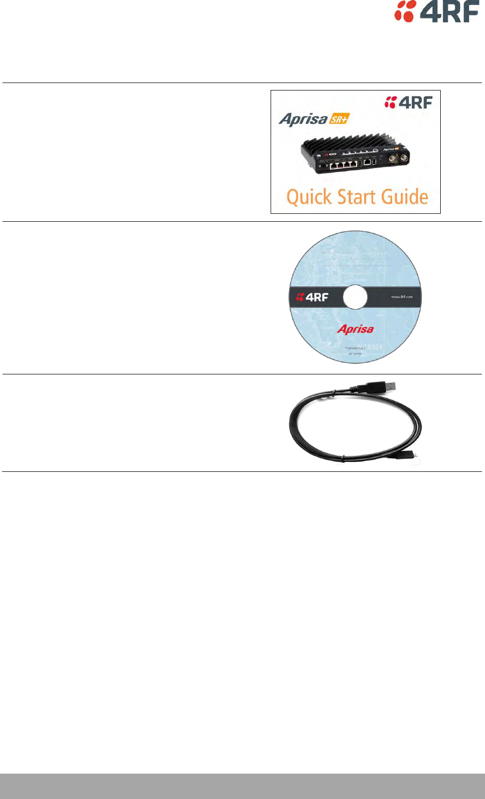
What’s in the Box
Inside the box you will find:
One Aprisa SR+ radio fitted with a power connector.
One Aprisa SR+ Accessory kit containing the following:
Aprisa SR+ CD
Aprisa SR+ Quick Start Guide
Management Cable
16 | Introduction
Aprisa SR+ User Manual 1.6.0 PO
Aprisa SR+ Accessory Kit
The accessory kit contains the following items:
Aprisa SR+ Quick Start Guide
Aprisa SR+ CD
Management Cable
USB Cable USB A to USB micro B, 1m
Aprisa SR+ CD Contents
The Aprisa SR+ CD contains the following:
Software
The latest version of the radio software (see ‘Software Upgrade’ on page 358)
USB Serial Driver
Web browsers - Mozilla Firefox and Internet Explorer are included for your convenience
Adobe™ Acrobat® Reader® which you need to view the PDF files on the Aprisa SR+ CD
Documentation
User manual - an electronic (PDF) version for you to view online or print
Product collateral - application overviews, product description, quick start guide, case studies,
software release notes and technical papers
About the Radio | 17
Aprisa SR+ User Manual 1.6.0 PO
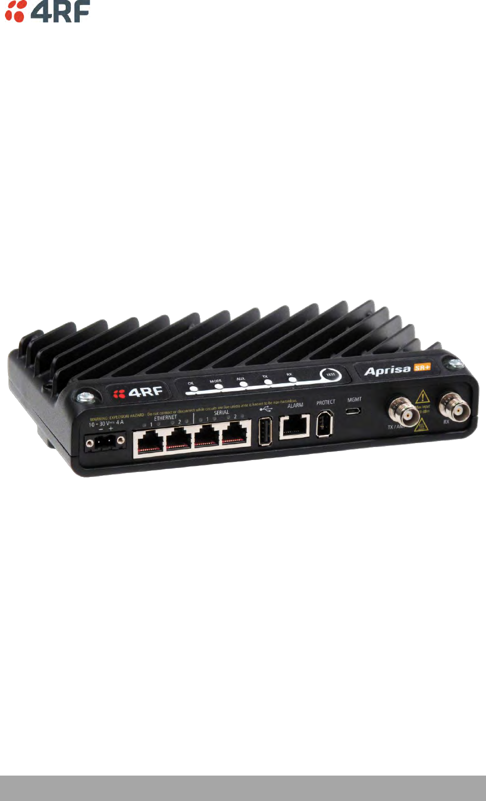
3. About the Radio
The 4RF Aprisa SR+ Radio
The 4RF Aprisa SR+ is a Point-To-Multipoint (PMP) and Point-To-Point (PTP) digital radio providing secure
narrowband wireless data connectivity for SCADA, infrastructure and telemetry applications.
The radios carry a combination of serial data and Ethernet data between the base station, repeater
stations and remote stations.
A single Aprisa SR+ is configurable as a:
Point-To-Multipoint base station, remote station, repeater station or a base-repeater station
Point-To-Point local or remote radio

18 | About the Radio
Aprisa SR+ User Manual 1.6.0 PO
Product Overview
Network Coverage and Capacity
The Aprisa SR+ has a typical link range of up to 120 km, however, geographic features, such as hills,
mountains, trees and foliage, or other path obstructions, such as buildings, will limit radio coverage.
Additionally, geography may reduce network capacity at the edge of the network where errors may occur
and require retransmission. However, the Aprisa SR+ uses 10W output power and Forward Error Correction
(FEC) which greatly improves the sensitivity and system gain performance of the radio resulting in less
retries and minimal reduction in capacity.
Ultimately, the overall performance of any specific network will be defined by a range of factors including
the RF output power, the modulation used and its related receiver sensitivity, the geographic location,
the number of remote stations in the base station coverage area and the traffic profile across the
network. Effective network design will distribute the total number of remote stations across the available
base stations to ensure optimal geographic coverage and network capacity.
One base station can register and operate with up to 500 remote / repeater stations.
The practical limit of remote / repeater stations that can operate with one base station is determined by
a range of factors including the number of services, the packet sizes, the protocols used, the message
types and network timeouts.
Automatic Registration
On start-up, the remote station transmits a registration message to the base station which responds with a
registration response. This allows the base station to record the details of all the remote stations active in
the network.
If a remote station cannot register with the base station after multiple attempts within 10 minutes, it will
automatically reboot. If remote is not able to register with base station in 5 attempts, then a ‘Network
Configuration Warning’ alarm event will be raised indicating that a remote is not registered with the base
station.
If a remote station has registered with the base station but then loses communication, it will
automatically reboot within 2 minutes.
Remote Messaging
There are two message types in the Aprisa SR+ network, broadcast messages and unicast messages.
Broadcast messages are transmitted by the base station to the remote stations and unicast messages are
transmitted by the remote station to the base station. These messages are commonly referred to as uplink
(unicast remote to base) and downlink (broadcast base to remote).
All remotes within the coverage area will receive broadcast messages and pass them on to either the
Ethernet or serial interface. The RTU determines if the message is intended for it and will accept it or
discard it.
About the Radio | 19
Aprisa SR+ User Manual 1.6.0 PO
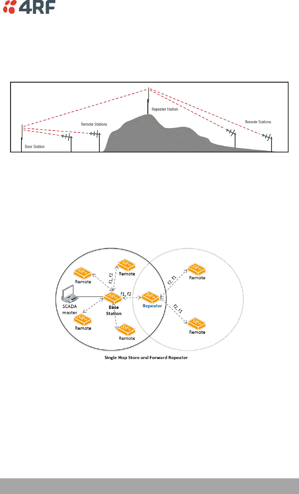
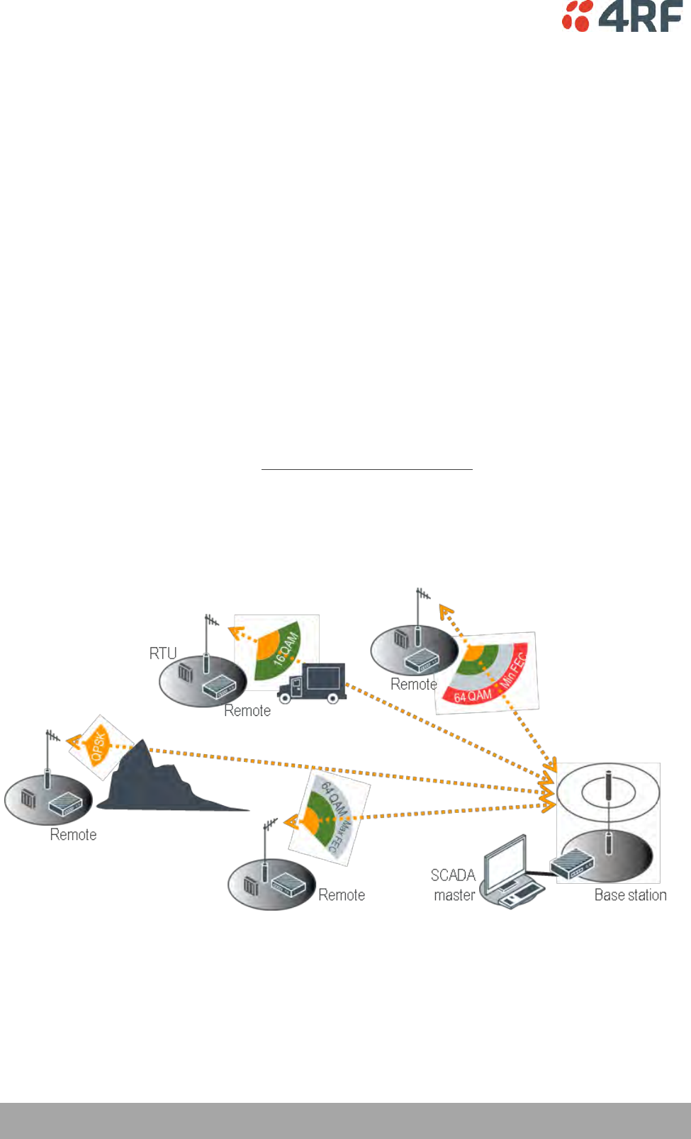
Store and Forward Repeater
The Aprisa SR+ in Repeater mode is used to link remote stations to the base station when direct
communication is not possible due to terrain, distance, fade margin or other obstructions in the network.
The following example depicts a repeater on the hill top to allow communication between the base
station and the remote stations on the other side of hilly terrain.
Repeater Packet Forwarding
The Aprisa SR+ works in packet Store and Forward (S&F) for simple and low cost repeater network.
Repeater mode is available in both Access Request (AR) and Listen Before Send (LBS/CSMA) MAC operating
modes. It allows a radio in Repeater mode to store a received packet and retransmit it.
Single Repeater Single Hop
The following example depicts an Aprisa SR+ single repeater single hop Store and Forward network.
20 | About the Radio
Aprisa SR+ User Manual 1.6.0 PO
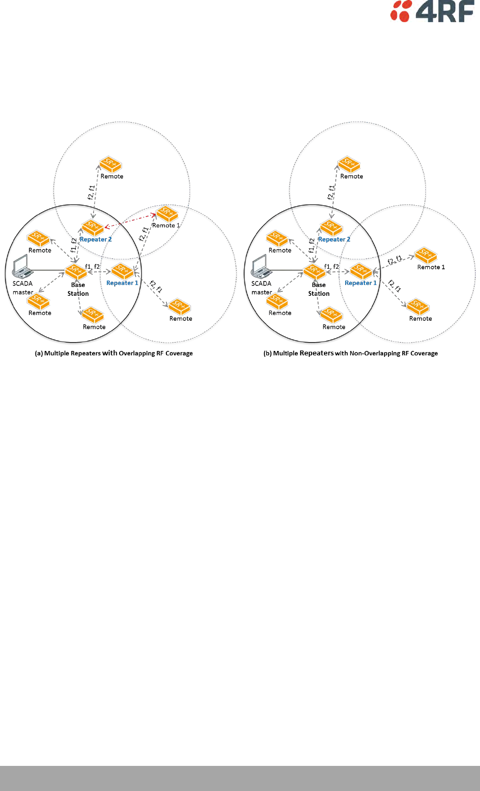
Multiple Repeater Single Hop
The following example depicts an Aprisa SR+ multiple repeater single hop store and forward network
supporting both overlapping and non-overlapping coverage repeater networks. An overlapped RF coverage
area creates radio interference and might affect network performance and reduce throughput, as show in
figure (a), where Remote 1 is in overlapped RF coverage with Repeater 1 and Repeater 2.
The Aprisa SR+ functionality allows repeaters in Bridge mode to forward Ethernet packets based on
Repeater Network Segment ID. The base station translates the destination address (DA) to the Repeater
Network Segment ID. This improves repeater performance by forwarding the packet if the Repeater
Network Segment ID belongs to the repeater branch and discards the packet if it doesn’t.
Router mode supports repeater packet forwarding based on IP destination address. This improves repeater
performance by forwarding the packet if the IP destination address belongs to the repeater branch and
discards the packet if it doesn’t
About the Radio | 21
Aprisa SR+ User Manual 1.6.0 PO
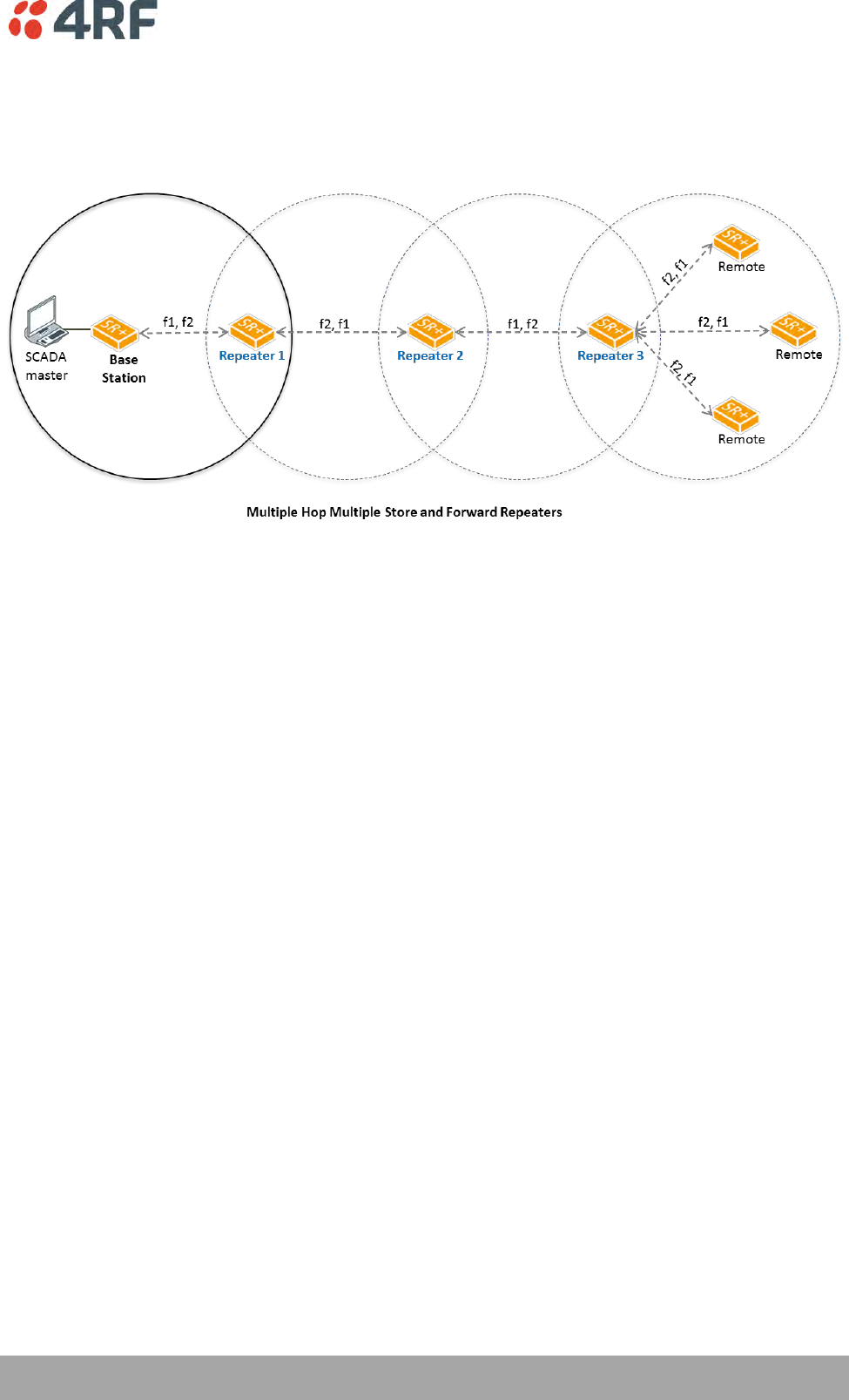
Multiple Repeater Multiple Hop
The following example depicts an Aprisa SR+ daisy chain multiple repeater multiple hop store and forward
network i.e. multiple hops and multiple repeaters in non-overlapping RF coverage. The Aprisa SR+ daisy
chain store and forward repeaters are currently supported in LBS MAC mode only.
In any type of store and forward repeater network base, repeater and remote radios must have their
Tx/Rx frequencies sets to match to their appropriate linking devices as shown in the figures.
Note: Frequencies shown in the figures relates to the device on the left where {Tx, Rx} = {fx, fy}. In this
example, the Base Station, Repeater 2 and remotes are deployed with Tx=f1 and Rx=f2. On the other hand
Repeater 1 and Repeater 3 are deployed with Tx=f2 and Rx=f1, creating the required linking for daisy
chain operation.

22 | About the Radio
Aprisa SR+ User Manual 1.6.0 PO
Repeater Messaging
The Aprisa SR+ uses a routed protocol throughout the network whereby messages contain source and
destination addresses. The remote and repeater stations will register with a base station. In networks with
a repeater, the repeater must register with the base station before the remotes can register with the base
station.
Additionally, based on destination address, messages are designated as either a ‘broadcast’ message,
(mostly originating from a base station) or a ‘unicast’ message (mostly originating from a remote station).
In a network with a repeater, or multiple repeaters, the base station broadcasts a message which contains
a source address and a destination address. The repeater receives the message and recognizes it as a
broadcast message, from the destination address and re-broadcasts the message across the network. In IP
routing mode all remote stations in the coverage area will receive the message but only the radio with the
destination address will act upon the message.
Similarly, the remote station will send a unicast message which contains a unicast destination address (the
base station). The repeater will receive this message; recognize the destination address and forward it to
the appropriate destination address.
In order to prevent repeater-repeater loops, a detection mechanism of ‘duplicate message’ and use of
unicast messaging in remote to base/repeater direction is used.
For example, in the Multiple Repeater Single Hop figure above, the topology is of Base, Repeater 1,
Repeater 2 and Remote 1 connected to Repeater 1 in overlapping coverage, where Remote 1 can also hear
Repeater 2. When the Base station broadcasts a message, Remote1 will receive this message from both
Repeater 1 and Repeater 2 but will drop one of them as ‘duplicate message’. It is possible that Repeater
1, for example, can also hear the broadcast sent out by Repeater 2. In this case, Repeater 1 will drop this
broadcast as a ‘duplicate message’.
These phenomena will not happen in the upstream direction as all messages are sent ‘unicast’. Remote 1
will send a packet to Base station, setting the destination address in packet to Base station and ‘next hop’
address in packet to Repeater 1. Thus, only Repeater 1 will forward the packet to Base station and
Repeater 2 will drop the packet as the ‘next hop’ address is not Repeater 2.
About the Radio | 23
Aprisa SR+ User Manual 1.6.0 PO
Peer To Peer Communication Between Remote Radios
The Aprisa SR+ peer to peer communication between remote radios is used to enable communication
between remote radios via the repeater or base-repeater. It is useful if the SCADA server or base station
fails or when in some industries like the water industry, where a reservoir remote station might send a
direct message to a valve remote station to close or open the valve without the intervention of the SCADA
server.
The Aprisa SR+ has a special operating mode for peer to peer communication between remote radios and
requires the following settings:
1. If peer to peer communication between remote radios is required to operate via the base station,
then the SuperVisor > Terminal > Operating Mode > Terminal operating mode must be set to ‘Base-
Repeater’. Base-Repeater operating mode doesn’t change the Network Radius parameter as the
base-repeater is considered to be like a regular base station.
2. The remote radios participating in peer to peer communication must set the SuperVisor > Radio >
Channel Setup > Packet Filtering to Disable to allow a repeated packet received from peer to peer
remote radios by the repeater or base-repeater to forward the packet to the relevant interface
and not to discard it.
3. IP Header Compression must be disabled on all radios (base, repeater, remotes) for this feature to
operate correctly (See ‘IP Header Compression Ratio’ on page 119).
4. The Network Repeaters Proximity must be set to ‘Base Repeater’ on all remote radios for this
feature to operate correctly (See ‘Network Repeaters Proximity’ on page 89’).
5. Note: In ‘Router Mode’ setup a static route for any required peer to peer path.
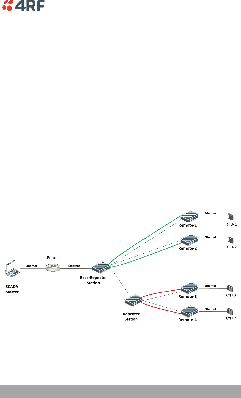
The following example depicts peer to peer communication between remote radios via a base-repeater
and via a repeater station where remote-1 and remote-2 communicate with each other via the base-
repeater station and remote-3 and remote-4 communicate with each other via the repeater station. All
the remote radios are configured with packet filtering disabled and all radios in the network are
configured with IP header compression ratio disabled.
Note: The Aprisa SR+ network is transparent to the protocol being transmitted; therefore the Packet
Filtering parameter is based on the Aprisa SR+ addressing and network protocols, not the user (SCADA,
etc.) traffic protocols.

24 | About the Radio
Aprisa SR+ User Manual 1.6.0 PO
Product Features
Functions
Point-to-Point (PTP) or Point-to-Multipoint (PMP) operation
Licensed frequency bands:
VHF 135 135-175 MHz
VHF 220 215-240 MHz
UHF 320 320-400 MHz
UHF 400 400-470 MHz
UHF 450 450-520 MHz
UHF 700 757-758 MHz and 787-788 MHz
UHF 896 896-902 MHz
UHF 928 928-960 MHz
Channel sizes – software selectable:
12.5 kHz
20 kHz
25 kHz
50 kHz
75 kHz
Adaptive Coding and Modulation (ACM): QPSK to 64 QAM
Half duplex or full duplex RF Point-To-Multipoint operation
Full duplex RF Point-To-Point operation
Ethernet data interface and RS-232 / RS-485 asynchronous multiple port options
Software selectable dual / single antenna port options (dual antenna port for external duplexers or
filters)
Data encryption and authentication using 128,192 and 256 bit AES and CCM security standards
Terminal server operation for transporting RS-232 / RS-485 traffic over IP or Ethernet and
converting IP packets to a local physical serial port
Mirrored Bits ® and SLIP support for RS-232
IEEE 802.1Q VLAN support with single and double VLAN tagged and add/remove VLAN manipulation
to adapt to the appropriate RTU / PLCs
QoS supports using IEEE 802.1p VLAN priority bits to prioritize and handle the VLAN / traffic types
QoS per port (Ethernet, serial, management)
L2 / L3 / L4 filtering for security and avoiding narrow band radio network overload
L3 Gateway Router mode with standard static IP route for simple routing network integration
L3 Router mode with per Ethernet interface IP address and subnet
L2 Bridge mode with VLAN aware for standard Industrial LAN integration
Ethernet header and IP/TCP / UDP ROHC header compression to increase the narrow band radio
capacity
Ethernet and serial payload compression to increase the narrow band radio capacity
Pseudo peer to peer communication between remote stations through base-repeater or repeater
stations
SuperVisor web management support for element and sub-network (base-repeater-remotes)
management
SNMPv1/2/3 & encryption MIB supports for 4RF SNMP manager or third party SNMP agent network
management

About the Radio | 25
Aprisa SR+ User Manual 1.6.0 PO
SNMP context addressing for compressed SNMP access to remote stations
SNTP for accurate wide radio network time and date
RADIUS security for remote user authorization, authentication and accounting
Build-configuration / flexibility of serial and Ethernet interface ports (3+1, 2+2, 4+0)
Radio and user interface redundancy (provided with Aprisa SR+ Protected Station)
Protected Station fully hot swappable and monitored hot standby
Power optimized with sleep modes
Transparent to all common SCADA protocols; e.g. Modbus, IEC 60870-5-101/104, DNP3 or similar
Complies with international standards, including ETSI, FCC, IC, ACMA, EMC, safety and
environmental standards
Security
The Aprisa SR+ provides security features to implement the key recommendations for industrial control
systems. The security provided builds upon the best in class from multiple standards bodies, including:
IEC/TR 62443 (TC65) ‘Industrial Communications Networks – Network and System Security’
IEC/TS 62351 (TC57) ‘Power System Control and Associated Communications – Data and
Communication Security’
FIPS PUB 197, NIST SP 800-38C, IETF RFC3394, RFC3610 and IEEE P1711/P1689/P1685
FIPS 140-2: Security Requirements for Cryptographic Modules
The security features implemented are:
Data encryption
Counter Mode Encryption (CTR) using Advanced Encryption Standard (AES) 128, 192, 256 bit,
based on FIPS PUB 197 AES encryption (using Rijndael version 3.0)
Data authentication
NIST SP 800-38C Cipher Block Chaining Message Authentication Code (CBC-MAC) based on RFC
3610 using Advanced Encryption Standard (AES)
Data payload security
CCM Counter with CBC-MAC integrity (NIST special publication 800-38C)
Secured management interface protects configuration
L2 / L3 / L4 Address filtering enables traffic source authorization
Proprietary physical layer protocol and modified MAC layer protocol based on standardized IEEE
802.15.4
Licensed radio spectrum provides recourse against interference
SNMPv3 with Encryption for NMS secure access
Secure USB software upgrade
Key Encryption Key (KEK) based on RFC 3394, for secure Over The Air Re-keying (OTAR) of
encryption keys
User privilege allows the accessibility control of the different radio network users and the user
permissions

26 | About the Radio
Aprisa SR+ User Manual 1.6.0 PO
Performance
Typical deployment of 30 remote stations from one base station with a practical limit of a few
hundred remote stations
Long distance operation
High transmit power
Low noise receiver
Forward Error Correction
Electronic tuning over the frequency band
Thermal management for high power over a wide temperature range
Usability
Configuration / diagnostics via front panel Management Port USB interface, Ethernet interface
Built-in webserver SuperVisor with full configuration, diagnostics and monitoring functionality,
including remote station configuration / diagnostics over the radio link
LED display for on-site diagnostics
Dedicated alarm port
Software upgrade and diagnostic reporting via the host port USB flash drive
Over-the-air software distribution and upgrades
Simple installation with integrated mounting holes for wall, DIN rail and rack shelf mounting
About the Radio | 27
Aprisa SR+ User Manual 1.6.0 PO
System Gain vs FEC Coding
This table shows the relationship between modulation, FEC coding, system gain, capacity and coverage.
Maximum FEC coding results in the highest system gain, the best coverage but the least capacity
Minimum FEC coding results in lower system gain, lower coverage but higher capacity
No FEC coding results in the lowest system gain, the lowest coverage but the highest capacity
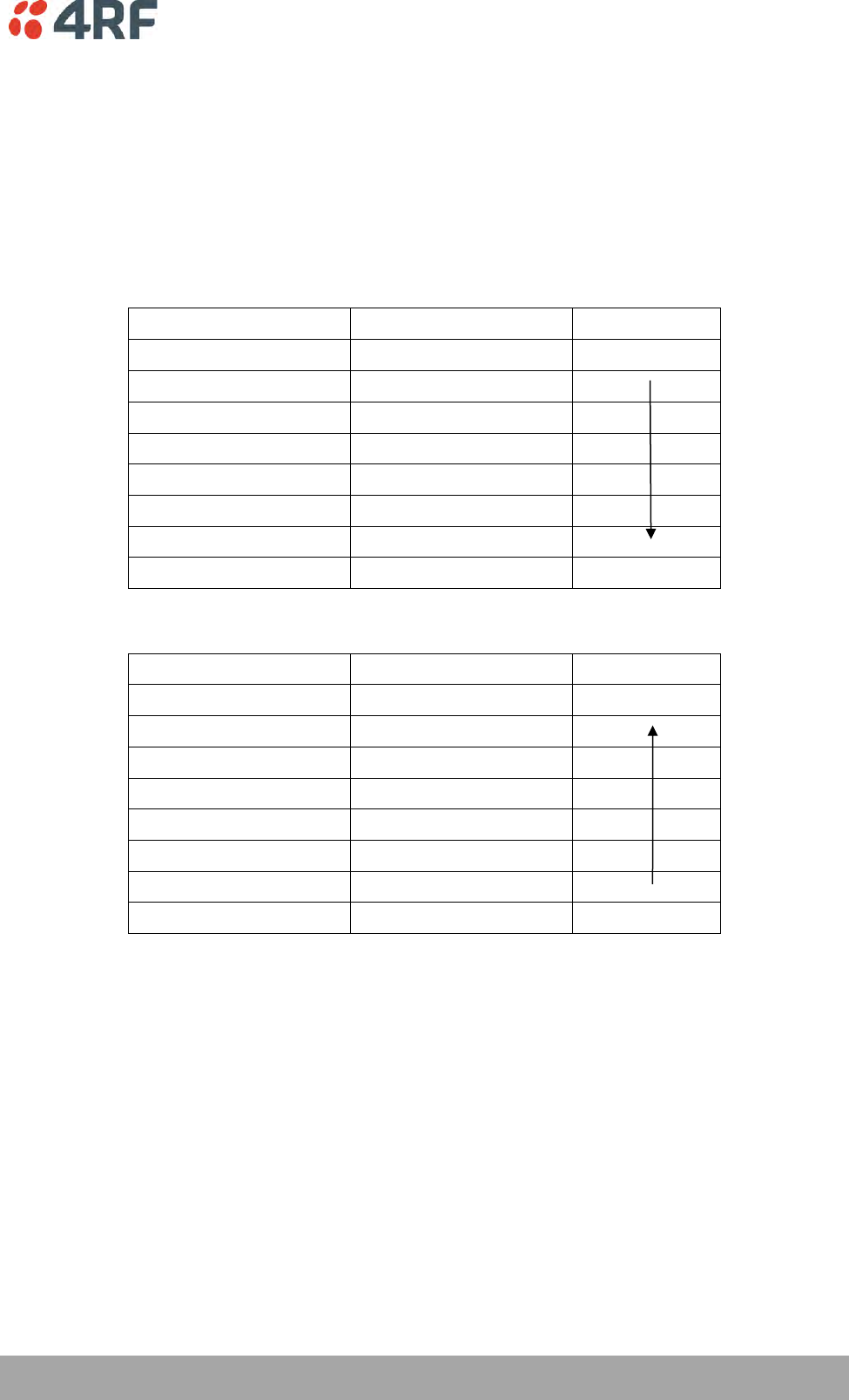
This table defines the modulation order based on gross capacity:
Modulation
FEC Coding
Capacity
QPSK (High Gain)
Max Coded FEC
Minimum
QPSK (Low Gain)
Min Coded FEC
16QAM (High Gain)
Max Coded FEC
QPSK
No FEC
16QAM (Low Gain)
Min Coded FEC
16QAM
No FEC
64QAM (High Gain)
Max Coded FEC
64QAM (Low Gain)
Min Coded FEC
Maximum
This table defines the modulation order based on receiver sensitivity:
Modulation
FEC Coding
Coverage
QPSK (High Gain)
Max Coded FEC
Maximum
QPSK (Low Gain)
Min Coded FEC
16QAM (High Gain)
Max Coded FEC
QPSK
No FEC
16QAM (Low Gain)
Min Coded FEC
64QAM (High Gain)
Max Coded FEC
16QAM
No FEC
64QAM (Low Gain)
Min Coded FEC
Minimum

28 | About the Radio
Aprisa SR+ User Manual 1.6.0 PO
Architecture
The Aprisa SR+ Architecture is based around a layered TCP/IP protocol stack:
Physical
Proprietary wireless
RS-232 and Ethernet interfaces
Link
Proprietary wireless (channel access, ARQ, segmentation)
VLAN aware Ethernet bridge
Network
Standard IP
Proprietary automatic radio routing table population algorithm
Transport
TCP, UDP
Application
HTTPS web management access through base station with proprietary management application
software including management of remote stations over the radio link
SNMPv1/2/3 for network management application software
Product Operation
There are three components to the wireless interface: the Physical Layer (PHY), the Data Link Layer (DLL)
and the Network Layer. These three layers are required to transport data across the wireless channel in
the Point-to-Multipoint (PMP) configuration. The Aprisa SR+ DLL is largely based on the 802.15.4 Media
Access Control (MAC) layer using a proprietary implementation.
Physical Layer
The Aprisa SR+ PHY uses a one or two frequency half duplex transmission mode which eliminates the need
for a duplexer. However, a Dual Antenna port option is available for separate transmit and receive
antenna connection to support external duplexers or filters (half duplex operation).
Remote nodes are predominantly in receive mode with only sporadic bursts of transmit data. This reduces
power consumption.
The Aprisa SR+ is a packet based radio. Data is sent over the wireless channel in discrete packets /
frames, separated in time. The PHY demodulates data within these packets with coherent detection.
The Aprisa SR+ PHY provides carrier, symbol and frame synchronization predominantly through the use of
preambles. This preamble prefixes all packets sent over the wireless channel which enables fast
Synchronization.

About the Radio | 29
Aprisa SR+ User Manual 1.6.0 PO
Data Link Layer / MAC layer
The Aprisa SR+ PHY enables multiple users to be able to share a single wireless channel; however a DLL is
required to manage data transport. The two key components to the DLL are channel access and hop by
hop transmission.
Channel Access
The Aprisa SR+ radio has two modes of channel access, Access Request and Listen Before Send.
Option
Function
Access Request
Channel access scheme where the base stations controls the
communication on the channel. Remotes ask for access to the
channel, and the base station grants access if the channel is not
occupied.
Listen Before Send
Channel access scheme where network elements listen to ensure
the channel is clear, before trying to access the channel.
Access Request
This scheme is particularly suited to digital SCADA systems where all data flows through the base station.
In this case it is important that the base station has contention-free access as it is involved in every
transaction. The channel access scheme assigns the base station as the channel access arbitrator and
therefore inherently it has contention-free access to the channel. This means that there is no possibility
of contention on data originating from the base station. As all data flows to or from the base station, this
significantly improves the robustness of the system.
All data messages are controlled via the AG (access grant) control message and therefore there is no
possibility of contention on the actual end user data. If a remote station accesses the channel, the only
contention risk is on the AR (access request) control message. These control messages are designed to be
as short as possible and therefore the risk of collision of these control messages is significantly reduced.
Should collisions occur these are resolved using a random back off and retry mechanism.
As the base station controls all data transactions multiple applications can be effectively handled,
including a mixture of polling and report by exception.
Access Request – Full Duplex
This scheme is used in a network with a full duplex base / master station and half duplex repeater /
remote stations. Full duplex Access Request utilizes the existing (half duplex) Access Request scheme as
described in the section above.
The base / master station can transmit while simultaneously receiving from the remote / repeaters. This
increases Access Request efficiency, especially in the report by exception scheme (spontaneous
messages).
This feature can be operated on full duplex hardware only (see ‘Product Options’ section on page 329).
If the Access Scheme is set to full duplex on a repeater, packets start to egress a repeater before the entire
packet has been received by the repeater. This scheme reduces latency on long packets through a repeater
and improves performance in Overlapping Coverage mode.
To allow this new MAC scheme to operate, two new RF Network Detail parameters have been added; Base
Station ID and Repeater Network Segment ID (see ‘Base Station ID’ on page 89 and ‘Repeater Network
Segment ID’ on page 90).
30 | About the Radio
Aprisa SR+ User Manual 1.6.0 PO
Listen Before Send
The Listen Before Send channel access scheme is realized using Carrier Sense Multiple Access (CSMA). In
this mode, a pending transmission requires the channel to be clear. This is determined by monitoring the
channel for other signals for a set time prior to transmission. This results in reduced collisions and
improved channel capacity.
There are still possibilities for collisions with this technique e.g. if two radios simultaneously determine
the channel is clear and transmit at the same time. In this case an acknowledged transaction may be used.
The transmitter requests an ACK to ensure that the transmission has been successful. If the transmitter
does not receive an ACK, then random backoffs are used to reschedule the next transmission.
Hop by Hop Transmission
Hop by Hop Transmission is realized in the Aprisa SR+ by adding a MAC address header to the packet. For
802.15.4, there are 2 addresses, the source and destination addresses.
Adaptive Coding and Modulation
The Aprisa SR+ provides Adaptive Coding and Modulation (ACM) which maximizes the use of the RF path to
provide the highest radio capacity available.
ACM automatically adjusts the modulation coding and FEC code rate in the remote to base direction of
transmission based on the signal quality for each individual remote radio.
When the RF path is healthy (no fading), modulation coding is increased and the FEC code rate is
decreased to maximize the data capacity.
If the RF path quality degrades, modulation coding is decreased and the FEC code rate is increased for
maximum robustness to maintain path connectivity.
About the Radio | 31
Aprisa SR+ User Manual 1.6.0 PO
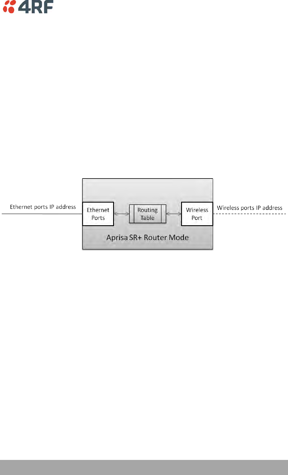
Network Layer
Packet Routing
Aprisa SR+ is a standard static IP router which routes and forwards IP packet based on standard IP address
and routing table decisions.
Aprisa SR+ router mode (see figure below), enables the routing of IP packets within the Aprisa SR+ wireless
network and in and out to the external router / IP RTUs devices connected to the Aprisa SR+ wired
Ethernet ports.
Within the Aprisa SR+ Router mode, each incoming Ethernet packet on the Ethernet port is stripped from
its Ethernet header to reveal the IP packet and to route the IP packet based on its routing table. If the
destination IP address is one of the RTUs, the packet is then forwarded to the wireless ports and
broadcasted as a PMP wireless packet to all the repeater / remotes stations. The appropriate remote then
routes the IP packet and forwards it based on its routing table to the appropriate Ethernet port,
encapsulating the appropriate next hop MAC header and forwarding it to the RTU. The RTU can then
interpret and process the IP data and communication is established between the RTU and the initiating
communication device.
32 | About the Radio
Aprisa SR+ User Manual 1.6.0 PO
Static IP Router
The Aprisa SR+ works in the point-to-multipoint (PMP) network as a standard static IP router with the
Ethernet and wireless / radio as interfaces and serial ports using terminal server as a virtual interface.
The Aprisa SR+ static router is semi-automated operation, where the routing table is automatically
created in the base station and populated with routes to all remotes and repeater stations in the network
during the registration process and vice versa, where the routing table is automatically created in remote
and repeater stations and populated with routes to base station during the registration process. Updates
occur when remote is disconnected from network for any reason, with the routing table updated in a
controlled fashion.
Also, in decommission operation, the base station routing tables are completely flushed allowing an
automatic rebuild. This avoids the user manually inserting / removing of multiple static routes to build /
change the routes in the network which might be tedious and introduce significant human error. The
Aprisa SR+ works as a static IP router without using any routing protocol and therefore does not have the
overhead of a routing protocol for better utilization of the narrow bandwidth network.
In addition to the semi-automated routes, the user can manually add / remove routes in the routing table
for the radio interface, Ethernet Interface and for routers which are connected to the radio network.
The Aprisa SR+ base station is used as a gateway to other networks. Thus, a configurable IP address
default gateway can be set using a static route in the routing table with a destination IP address of the
destination network address. It is recommended to use a real network IP address (actual device IP) for the
gateway and not 0.0.0.0.
The Aprisa SR+ sub-netting rules distinguish between the wireless interface and the remote Ethernet
interface where RTUs are connected. The entire wireless network is set on a single IP subnet, while each
Aprisa SR+ remote’s Ethernet interface is set to a different subnet network. In this way, the user can
easily distinguish between the remotes subnet IP addresses.
About the Radio | 33
Aprisa SR+ User Manual 1.6.0 PO
The Radio Network as a Gateway Router
The Aprisa SR+ point-to-multipoint radio network can be considered as a gateway router where the
‘network Ethernet interface’ on each radio in the network is the ‘router port’.
The routing table for all directly attached devices to the Aprisa SR+ network, at the Base or the Remote
stations is automatically built and no static routes are required to be entered for those device routes.
The ‘Radio interface IP address’ is used internally for the radio network and automatic routes. It is not
used when setting static routes or default gateways.
Static route IP addresses or the default gateway should use the ‘network Ethernet interface’ IP address.
External network routers should be set with a high metric for the SR+ path, to prevent route updates
being sent over the radio network.
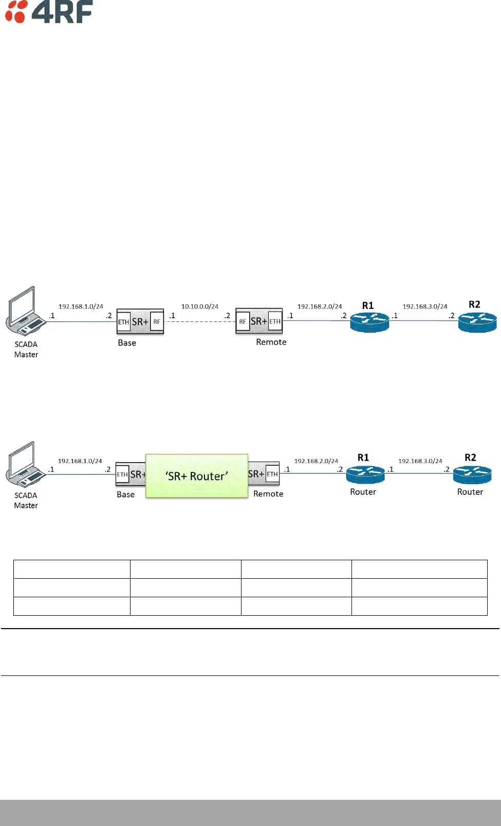
The Radio Network as a Router – Example
The purpose of this example is to determine the static route setting for router R2 in the base station and
remote station in the following network.
Since the Aprisa SR+ network should be considered as a router where the network Ethernet interface is the
‘router port’, the network configuration for setting the static routes or the default gateway IP addresses is
described in the follow figure:
Thus, the static route setting for router R2 at the Aprisa SR+ base station and remote station will be:
Destination Address
Destination Mask
Gateway Address
Static Route Setting at ?
192.168.3.0
255.255.255.0
192.168.2.1
Base station
192.168.3.0
255.255.255.0
192.168.2.2
Remote station
Note: The radio network (base station and remote stations) will automatically build routes to the attached
device e.g. SCADA Master station or attached router e.g. router R1 so static routes are not required for
these devices.

34 | About the Radio
Aprisa SR+ User Manual 1.6.0 PO
Static IP Router – Human Error Free
To ensure correct operation, the Aprisa SR+ router base station alerts when one (or more) of the devices is
not configured for router mode or a duplicated IP is detected when manually added.
When the user changes the base station IP address / subnet, the base station sends an ARP unsolicited
announcement message and the remotes / repeaters auto-update their routing table accordingly. This also
allows the router that is connected to the base station to update its next hop IP address and its routing
table.
When the user changes the remote / repeater station IP address / subnet, a re-registration process in the
base station then auto-updates its routing table accordingly.
Terminal Server - Transition to Converged Ethernet / IP Network
Customers that are transitioning their SCADA network to an Ethernet / IP SCADA network, can
simultaneously operate their legacy serial RTUs, not as a separate serial network to the new Ethernet / IP
network, but as part of the Ethernet / IP network, by using the terminal server feature.
The Aprisa SR+ terminal server is an application running in the radio that encapsulates serial traffic into
Ethernet / IP traffic. For SCADA networks, this enables the use of both serial and Ethernet / IP RTUs
within an Ethernet / IP based SCADA network.
About the Radio | 35
Aprisa SR+ User Manual 1.6.0 PO
Bridge Mode with VLAN Aware
Ethernet VLAN Bridge / Switch Overview
The Aprisa SR+ in Bridge mode of operation is a standard Ethernet Bridge based on IEEE 802.1d or VLAN
Bridge based on IEEE 802.1q/p which forward / switch Ethernet packet based on standard MAC addresses
and VLANs using FDB (forwarding database) table decisions. VLAN is short for Virtual LAN and is a virtual
separate network, within its own broadcast domain, but across the same physical network.
VLANs offer several important benefits such as improved network performance, increased security and
simplified network management.
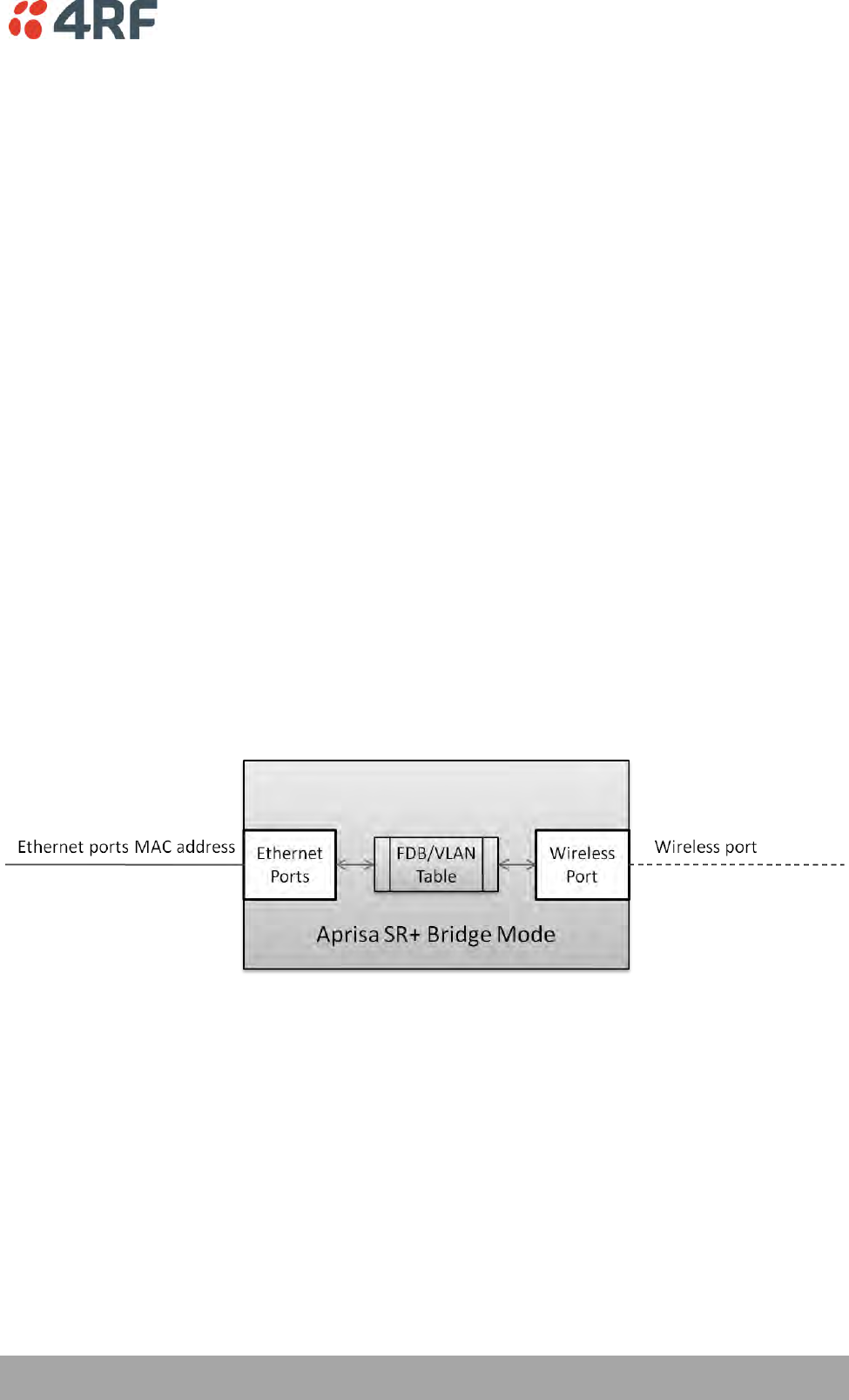
The Aprisa SR+ Bridge mode (see figure below), is the default mode of operation and it enables the
switching / bridging of Ethernet VLAN tagged or untagged packets within the Aprisa SR+ wireless network
and in and out to the external Industrial LAN network and RTUs devices connected to the Aprisa SR+ wired
Ethernet ports or serial ports through the terminal server function.
Within the Aprisa SR+ Bridge mode, each incoming Ethernet packet is inspected for the destination MAC
address (and VLAN) and looks up its FDB table for information on where to send the specific Ethernet
frame. If the FDB table doesn’t contain the specific MAC address, it will flood the Ethernet frame out to
all ports in the broadcast domain and when using VLAN, the broadcast domain is narrowed to the specific
VLAN used in the packet (i.e. broadcast will be done only to the ports which configured with that specific
VLAN).
The FDB table is used to store the MAC addresses that have been learnt and the ports associated with that
MAC address. If the destination MAC address is one of the RTUs, the packet is then forwarded to the
wireless ports and broadcast as a PMP wireless packet to all the repeater / remote stations. The
appropriate remote then switches the Ethernet packet and forwards it based on its FDB table (based on
the MAC or VLAN & MAC) to the appropriate Ethernet port to the RTU. The RTU can then interpret and
process the Ethernet / IP data and communication is established between the RTU and the initiating
communication device.
36 | About the Radio
Aprisa SR+ User Manual 1.6.0 PO
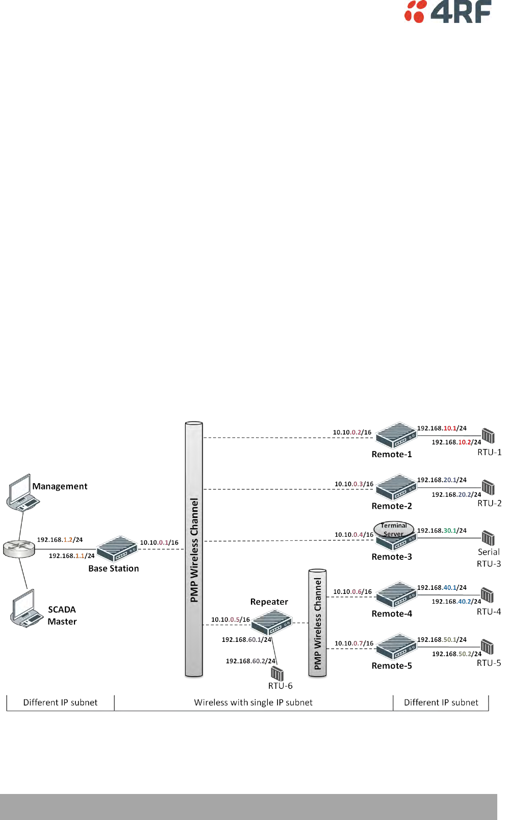
VLAN Bridge Mode Description
General – Aprisa SR+ VLAN Bridge
The Aprisa SR+ works in a point-to-multipoint (PMP) network as a standard VLAN bridge with the Ethernet
and wireless / radio as interfaces and serial ports using terminal server as a virtual interface.
The Aprisa SR+ is a standard IEEE 802.1q VLAN bridge, where the FDB table is created by the bridge
learning / aging process. New MACs are learnt and the FDB table updated. Unused MACs are aged out and
flushed automatically after aging period.
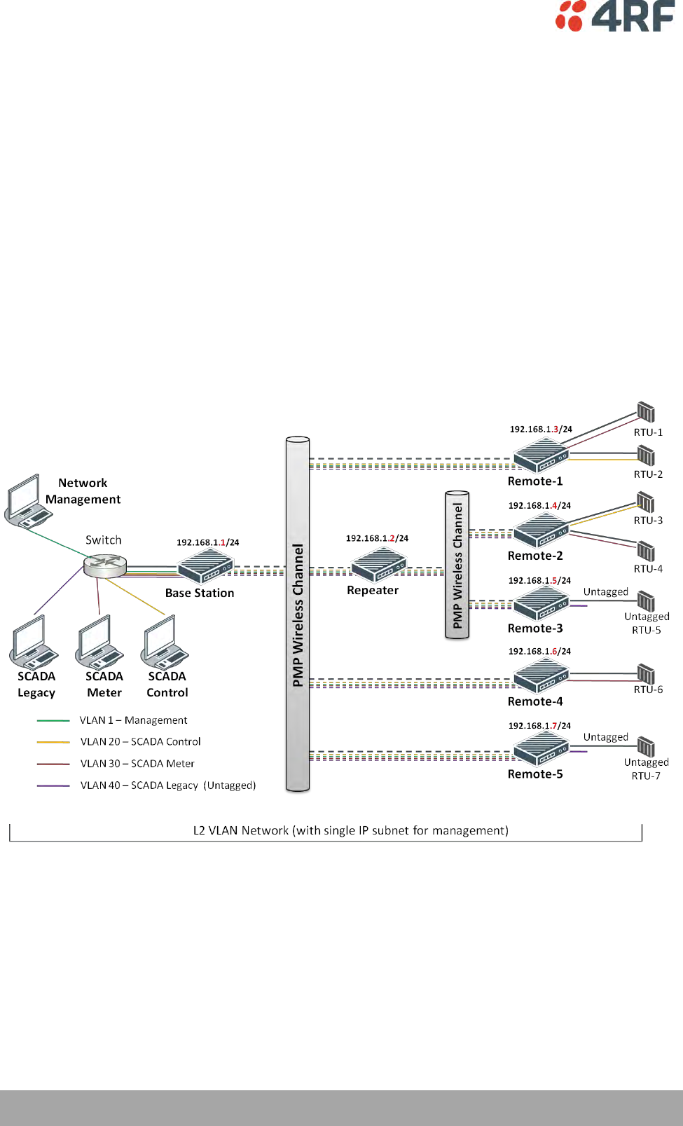
VLANs are statically configured by the user on the ports where a Virtual LAN is required across the radio
network. An example of VLAN isolation of traffic type is shown in the figure below, where RTUs #1, 4 and
6 together with SCADA meter master form a Virtual LAN which is isolated from the other devices, even
though they are on the same physical network. VLAN management can be used to manage with external
NMS all the Aprisa SR+ devices on the radio network and is automatically created with a VLAN ID = 1
default value. The VLAN ID can be changed by the user later on.
Each device in the Aprisa SR+ bridge is identified by its own IP address, as shown in the figure.

About the Radio | 37
Aprisa SR+ User Manual 1.6.0 PO
VLANs – Single, Double and Trunk VLAN ports
The Aprisa SR+ supports single VLAN (CVLAN), double VLAN (SVLAN) and trunk VLAN.
A single VLAN can be used to segregate traffic type.
A double VLAN can be used to distinguish between Aprisa SR+ sub-networks (base-repeater-remote),
where the outer SVLAN is used to identify the sub-network and the CVLAN is used to identify the traffic
type. In this case, a double tagged VLAN will be forwarded across the Industrial LAN network and switched
based on the SVLAN to the appropriate Aprisa SR+ sub-network. When packet enters the Aprisa SR+
network, the SVLAN will be stripped off (removed) and the forwarding will be done based on the CVLAN,
so only a single VLAN will pass through over the radio network and double VLAN will be valid on the
borders of the radio network.
Trunk VLAN is also supported by the Aprisa SR+ where the user can configure multiple VLANs on a specific
Ethernet port, creating a trunk VLAN port. For example, in the above figure, a single trunk VLAN port is
created between the switch and the Aprisa SR+ base station, carrying VLAN ID #1, 20, 30 and 40.
VLAN Manipulation – Add / Remove VLAN Tags
In order to support double VLAN and different device types connected to the Aprisa SR+ e.g. switches,
RTUs, etc, which can be VLAN tagged or untagged / plain Ethernet devices, add / remove VLAN
manipulation is required.
In an Aprisa SR+ VLAN tagged network, a remote Aprisa SR+ connected to a plain RTU without VLAN
support, will remove (strip-off) the VLAN tag from the packet before sending it to the RTU. On the other
direction, when the RTU is sending an untagged packet, the Aprisa SR+ will add (append) an appropriate
user pre-configure VLAN tag before sending it over the air to the base station. This is shown in the above
figure on untagged RTU #5 and 7.
QoS using VLAN
VLANs carry 3 priority bits (PCP field) in the VLAN tag allowing prioritization of VLAN tagged traffic types
with 8 levels of priority (where 7 is the highest priority and 0 is the lowest priority). The Aprisa SR+
supports QoS (Quality of Service) where the priority bits in the VLAN tagged frame are evaluated and
mapped to four priority levels and four queues supported by the Aprisa SR+ radio. Packets in the queues
are then scheduled out in a strict priority fashion for transmission over-the-air as per the priority level
from high to low.

38 | About the Radio
Aprisa SR+ User Manual 1.6.0 PO
Avoiding Narrow Band Radio Traffic Overloading
The Aprisa SR+ supports mechanisms to prevent narrowband radio network overload:
1. L3/L4 Filtering
The L3 filtering can be used to block undesired traffic from being transferred on the narrow band channel,
occupying the channel and risking the SCADA critical traffic. L3/4 filtering has the ability to block a known
IP address and applications using TCP/IP or UDP/IP protocols with multiple filtering rules. The L3 (/L4)
filter can block/forward (discard/process) a specific IP address and a range of IP addresses. Each IP
addressing filtering rule set can also be set to filter a L4 TCP or UDP port/s which in most cases relates to
specific applications as per IANA official and unofficial well-known ports. For example, filter and block E-
mail SMTP or TFTP protocol as undesired traffic over the SCADA network. The user can block a specific or
range of IP port addresses, examples SMTP (Simple Mail Transfer Protocol) TCP port 25 or TFTP (Simple
Trivial File Transfer Protocol) UDP port 69.
2. L2 Address Filtering
L2 Filtering (Bridge Mode) provides the ability to filter radio link traffic based on specified Layer 2 MAC
addresses. Destination MAC (DA) addresses and a Source MAC (SA) addresses and protocol type (ARP, VLAN,
IPv4, IPv6 or Any type) that meet the filtering criteria will be transmitted over the radio link. Traffic that
does not meet the filtering criteria will not be transmitted over the radio link.
3. L2 Port VLANs Ingress Filtering and QoS
Double VLAN (Bridge Mode)
Double VLAN is used to distinguish/segregate between different radio sub-networks (Base-repeaters-
remotes). Traffic with double VLANs which are not destined to a specific sub-network will be discarded on
the ingress of the radio sub-network, avoiding the overload of the radio sub-network.
Single VLAN (Bridge Mode)
Single VLAN is used to distinguish/segregate between different traffic types assigned by the user in its
industrial corporate LAN. In order to avoid the overload of the radio network, traffic with single VLANs
which are not destined to a specific radio network will be discarded on the Ethernet ingress port of the
radio network. All single VLANs which set and are eligible will be transmitted over the radio link.
QoS using 802.1p priority bits (Bridge Mode)
The priority bits can be used in the VLAN tagged frames to prioritized critical mission SCADA traffic and
ensure SCADA traffic transmission relative to any other unimportant traffic. In this case, traffic based on
VLAN priority (priority 0 to 7) enters one of the four priority queues of the Aprisa SR+ (Very High, High,
Medium and Low). Traffic leaves the queues (to the radio network) from highest priority to lowest in a
strict priority fashion.
4. Ethernet port QoS
The Aprisa SR+ supports ‘Ethernet Per Port Prioritization’. Each Ethernet port can be assigned a priority
and traffic shall be prioritized accordingly. This is quite useful in networks where customers do not use
VLANs or cannot use 802.1p prioritization.

About the Radio | 39
Aprisa SR+ User Manual 1.6.0 PO
5. Ethernet Data and Management Priority and Background Bulk Data Transfer Rate
Alternatively to VLAN priority, users can control the Ethernet traffic priority (vs serial), management
priority and rate in order to control the traffic load of the radio network, where important and high
priority data (SCADA) will pass-through first assuring SCADA network operation. The user can set the use of
the Ethernet Data Priority, which controls the priority of the Ethernet customer traffic relative to the
serial customer traffic and can be set to one of the four queues. The Ethernet Management Priority
controls the priority of the Ethernet management traffic relative to Ethernet customer traffic and can be
set to one of the four queues. The Background Bulk Data Transfer Rate sets the data transfer rate (high,
medium, low) for large amounts of management data.
6. Ethernet Packet Time to Live
Another aspect of avoiding overload radio network is the Ethernet packet TTL, which is used to prevent
old, redundant packets being transmitted through the radio network. This sets the time an Ethernet
packet is allowed to live in the system before being dropped if it cannot be transmitted over the air.
7. Robust Header Compression (ROHC) and Payload Compression
Aprisa SR+ supports ROHC (Robust Header Compression RFC3095). ROHC is a standard way to compress IP,
UDP and TCP headers and this significantly increases IP traffic throughput especially in narrow band
network.
Aprisa SR+ supports payload compression. A Lempel–Ziv (LZ) algorithm is used to efficiently compress up to
50% traffic with high percentage of repetitive strings. Both serial and Ethernet / IP payload traffic are
compressed.

40 | About the Radio
Aprisa SR+ User Manual 1.6.0 PO
Interfaces
Antenna Interface
2 x TNC, 50 ohm, female connectors
Single or dual antenna ports (with or without the use of external duplexer / filter)
Ethernet Interface
2, 3 or 4 ports 10/100 base-T Ethernet layer 2 switch using RJ45
Used for Ethernet user traffic and radio sub-network management.
RS-232 / RS-485 Interface
2, 1 or 0 RS-232 asynchronous ports using RJ45 connector
Optional 1x RS-232 or RS-485 asynchronous port using USB host port with USB to RS-232 or USB to
RS-485 converters
USB Interfaces
1 x Management port using USB micro type B connector
Used for product configuration with the Command Line Interface (CLI).
1 x Host port using USB standard type A connector
Used for software upgrade, diagnostic reporting and configuration save / restore.
Protect Interface
1x Protect interface port
Used for the Protected Station operation.
Alarms Interface
1x Alarm port using RJ45 connector
Used to provide 2 x hardware alarm inputs and 2 x hardware alarm outputs
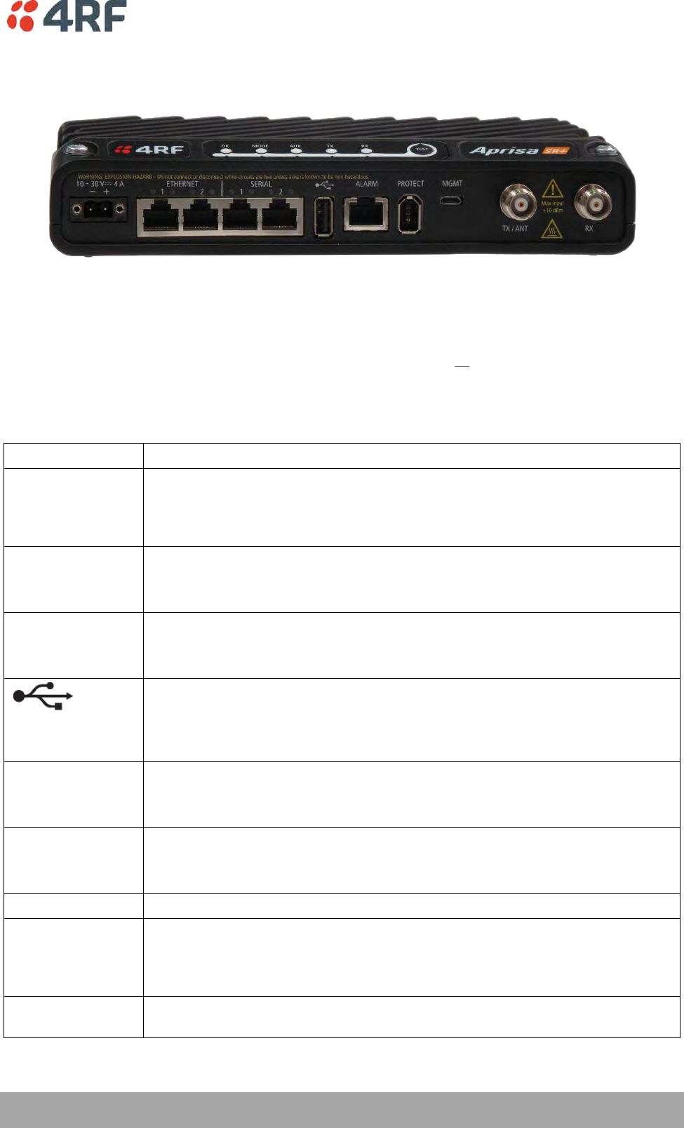
About the Radio | 41
Aprisa SR+ User Manual 1.6.0 PO
Front Panel Connections
Example; 2 Ethernet ports and 2 RS-232 serial ports - see ‘Data Interface Ports’ on page 329 for the other
interface port options.
Interface Port Option
Part Number
2 Ethernet ports and 2 RS-232 serial ports
APSQ-N400-SSC-HD-22-ENAA
All connections to the radio are made on the front panel. The functions of the connectors are (from left to
right):
Designator
Description
10 - 30 VDC; 3A
+10 to +30 VDC (negative ground) DC power input using Molex 2 pin male screw
fitting connector.
AC/DC and DC/DC power supplies are available as accessories. See ‘External
Power Supplies’ on page 63.
ETHERNET 1 & 2
Integrated 10Base-T/100Base-TX layer-3 Ethernet switch using RJ45 connectors.
Used for Ethernet user traffic and product management.
See ‘Ethernet > Port Setup’ on page 138.
SERIAL 1 & 2
Two ports of RS-232 serial using RJ45 connectors.
Used for RS-232 asynchronous user traffic.
See ‘Serial > Port Setup’ on page 124.
Host Port using a USB standard type A connector.
Used for software upgrade and diagnostic reporting and optional: 1x RS-232
asynchronous port with USB to RS-232 converter.
See ‘Software Upgrade’ on page 358 and ‘Maintenance > General’ on page 208.
ALARM
Alarm Port using a RJ45 connector.
Used for two alarm inputs and two alarm outputs.
See ‘Hardware Alarms Interface’ on page 396.
MGMT
Management Port using a USB micro type B connector.
Used for product configuration with the Command Line Interface.
See ‘Connecting to the Management Port’ on page 322.
PROTECT
Protect port. Used for Protected Station operation.
TX / ANT
TNC, 50 ohm, female connector for connection of antenna feeder cable for half
duplex RF operation or the Transmit connection to an external duplexer for full
duplex RF operation or to an external filter.
See ‘Coaxial Feeder Cables’ on page 55.
RX
TNC, 50 ohm, female connector for the Receive connection to an external
duplexer for full duplex RF operation or to an external filter.
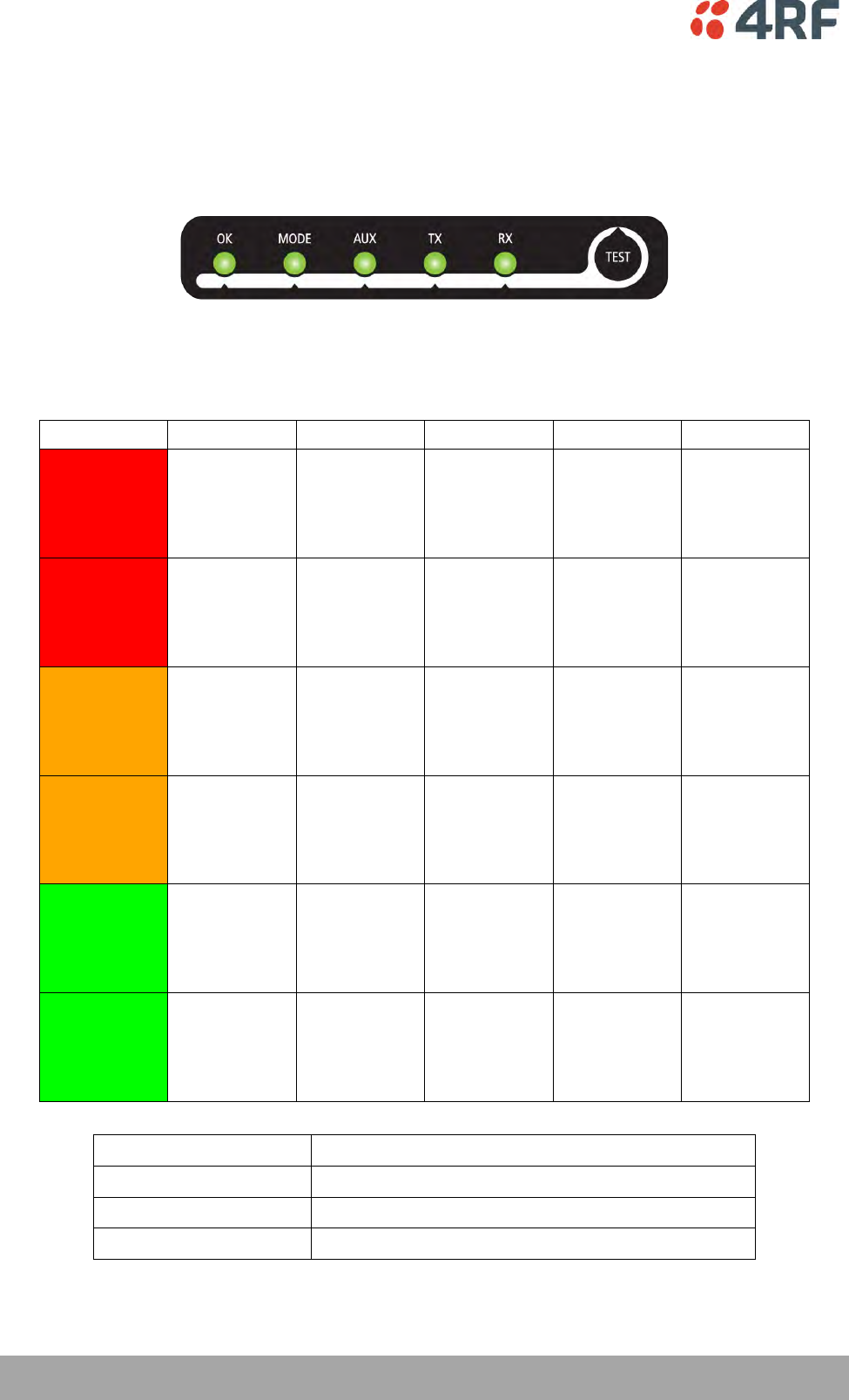
42 | About the Radio
Aprisa SR+ User Manual 1.6.0 PO
LED Display Panel
The Aprisa SR+ has an LED Display panel which provides on-site alarms / diagnostics without the need for
PC.
Normal Operation
In normal radio operation, the LEDs indicate the following conditions:
OK
MODE
AUX
TX
RX
Flashing
Red
Radio has not
registered
Solid
Red
Alarm present
with severity
Critical, Major
and Minor
TX path fail
RX path fail
Flashing
Orange
Diagnostics
Function
Active
OTA software
distribution
Management
traffic on the
USB MGMT
port
Solid
Orange
Alarm present
with Warning
Severity
Device detect
on the USB
host port
(momentary)
Flashing
Green
Software
Upgrade
Successful
Stand-by radio
in protected
station
Tx / Rx Data
on the USB
host port
RF path TX is
active
RF path RX is
active
Solid
Green
Power on and
functions OK
and no alarms
Processor
Block is OK
or active radio
in protected
station
USB interface
OK
Tx path OK
Rx path OK
LED Colour
Severity
Green
No alarm – information only
Orange
Warning alarm
Red
Critical, major or minor alarm

About the Radio | 43
Aprisa SR+ User Manual 1.6.0 PO
Single Radio Software Upgrade
During a radio software upgrade, the LEDs indicate the following conditions:
Software upgrade started - the OK LED flashes orange
Software upgrade progress indicated by running AUX to MODE LEDs
Software upgrade completed successfully - the OK LED flashes green
Software upgrade failed - any LED flashing red during the upgrade
Network Software Upgrade
During a network software upgrade, the MODE LED flashes orange on the base station and all remote
stations.
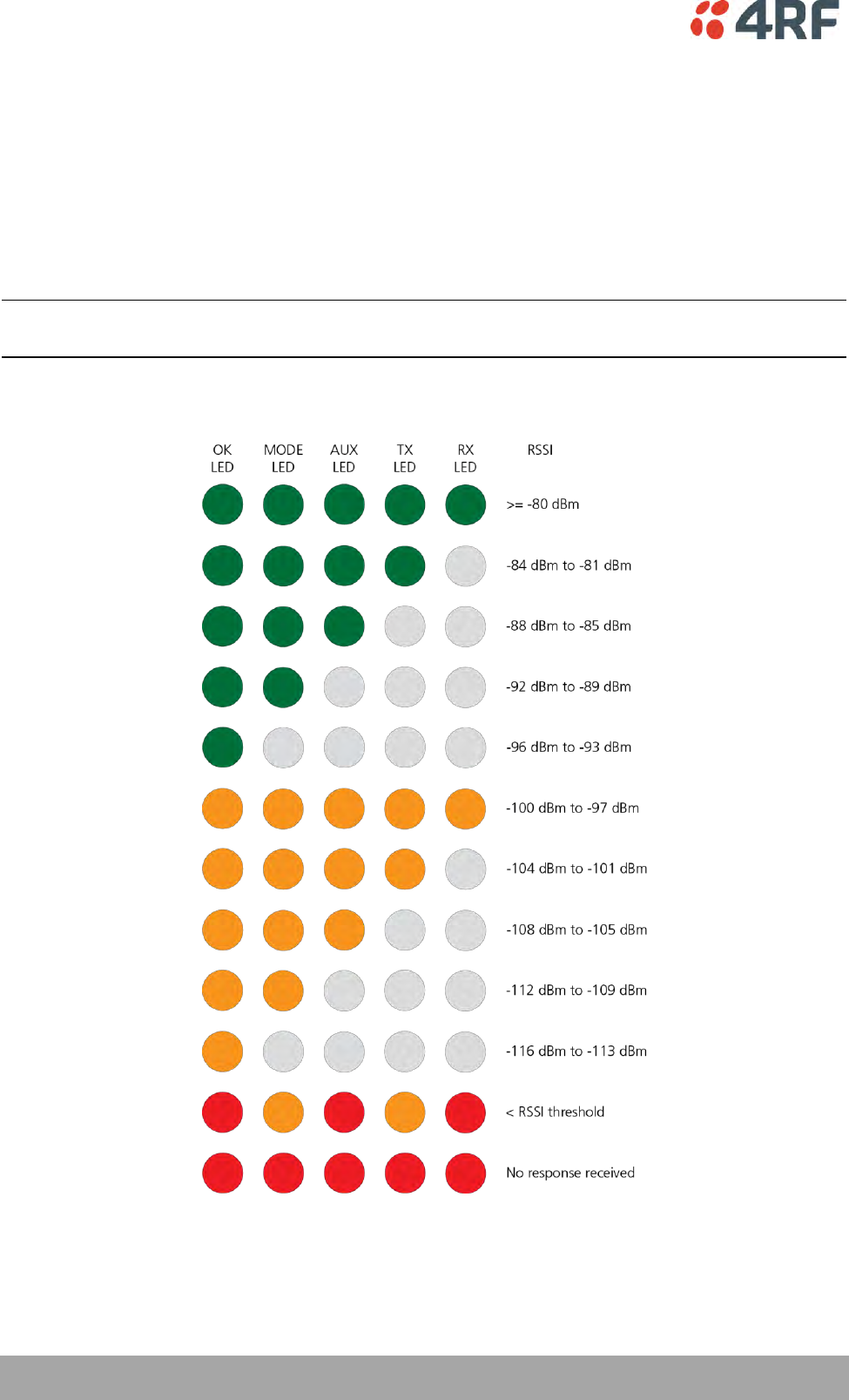
44 | About the Radio
Aprisa SR+ User Manual 1.6.0 PO
Test Mode
Remote station and repeater station radios have a Test Mode which presents a real time visual display of
the RSSI on the LED Display panel. This can be used to adjust the antenna for optimum signal strength (see
‘Maintenance > Test Mode’ on page 210 for Test Mode options).
To enter Test Mode, press and hold the TEST button on the radio LED panel until all the LEDs flash green
(about 3 - 5 seconds). The response time is variable and can be up to 5 seconds.
To exit Test Mode, press and hold the TEST button until all the LEDs flash red (about 3 – 5 seconds).
Note: Test Mode traffic has a low priority but could affect customer traffic depending on the relative
priorities setup.
The RSSI result is displayed on the LED Display panel as a combination of LED states:

About the Radio | 45
Aprisa SR+ User Manual 1.6.0 PO
Network Management
The Aprisa SR+ contains an embedded web server application (SuperVisor) to enable element management
with any major web browser (such as Mozilla Firefox or Microsoft® Internet Explorer).
SuperVisor enables operators to configure and manage the Aprisa SR+ base station radio and repeater /
remote station radios over the radio link.
The key features of SuperVisor are:
Full element management, configuration and diagnostics
Manage the entire network from the Base Station (remote management of elements)
Managed network software distribution and upgrades
Performance and alarm monitoring of the entire network, including RSSI, alarm states, time-
stamped events, etc.
View and set standard radio configuration parameters including frequencies, transmit power,
channel access, serial, Ethernet port settings
Set and view security parameters
User management
Operates over a secure HTTPS session on the access connection to the base station
SuperVisor, when connected to the base station radio allows management of all radios in the network. The
Network Table displays a list of all the registered remote stations for the base station and provides
management access to each of the remote stations (see ‘Network Status > Network Table’ on page 271).
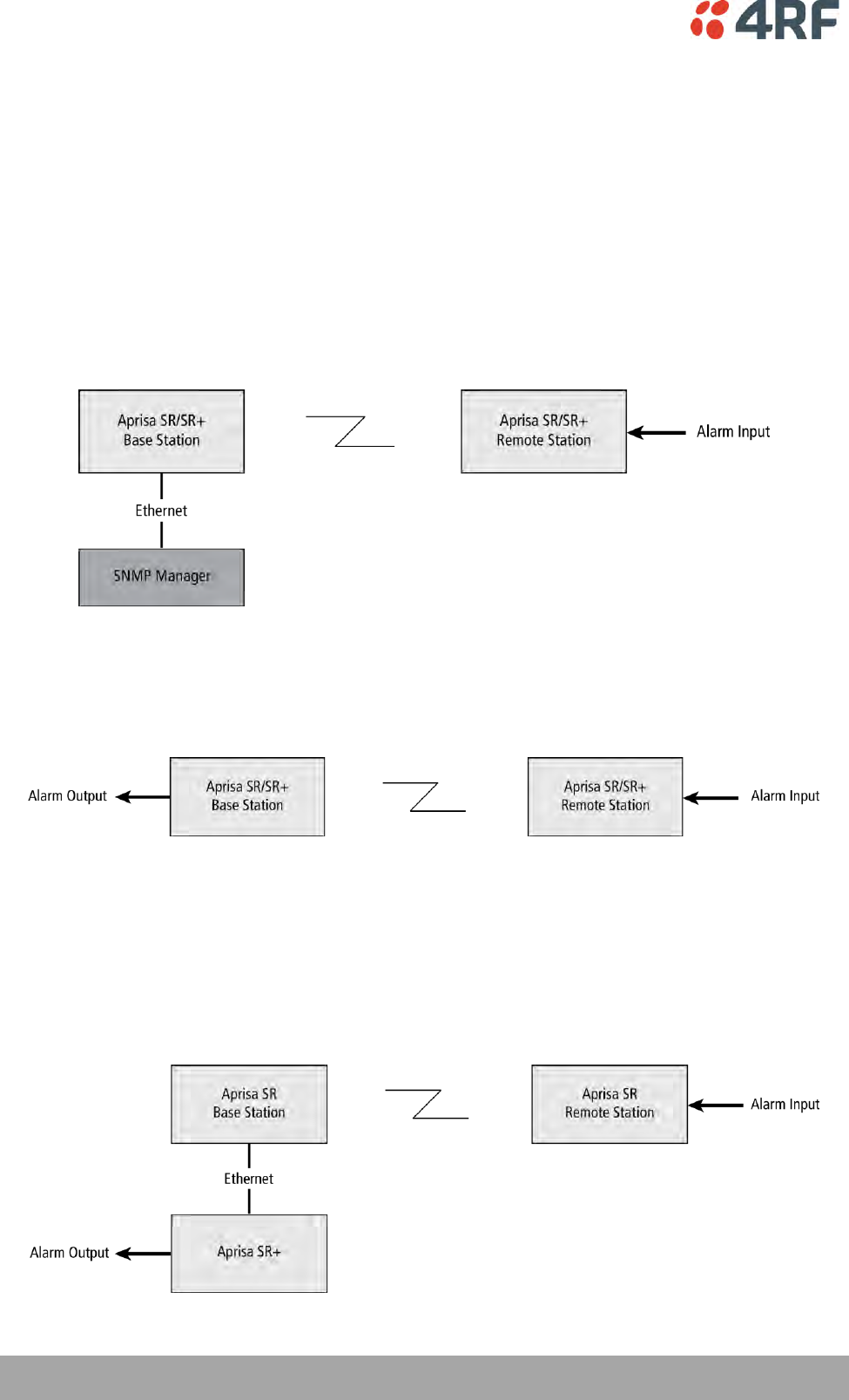
46 | About the Radio
Aprisa SR+ User Manual 1.6.0 PO
Hardware Alarm Inputs / Outputs
The Aprisa SR+ provides two hardware alarm inputs to generate alarm events in the network and two
hardware alarm outputs to receive alarm events from the network.
The hardware alarm inputs and outputs are part of the event system. All alarm events can be viewed in
SuperVisor event history log (see ‘Events > Event History’ on page 223). These include the alarm events
generated by the hardware alarm inputs.
Alarm Input to SNMP Trap
An alarm event from an Aprisa SR+ hardware alarm input can be sent over the air to any SNMP Manager
using SNMP traps.
Alarm Input to Alarm Output
An alarm event from an Aprisa SR+ hardware alarm input can be mapped to an hardware alarm output of
another SR+ using an event action setup (see ‘Events > Event Action Setup’ on page 231).
Aprisa SR Alarm Input to Aprisa SR+ Alarm Output
The Aprisa SR+ event action setup feature is compatible with the Aprisa SR.
Since, the Aprisa SR only supports hardware alarm inputs, the Aprisa SR+ can be used as an option to
provide a hardware alarm output. As shown in the figure below, an Aprisa SR+ connected on the same IP
network of the Aprisa SR, alarm events from the SR hardware alarm input can be mapped to the hardware
alarm output of the SR+ using an event action setup.
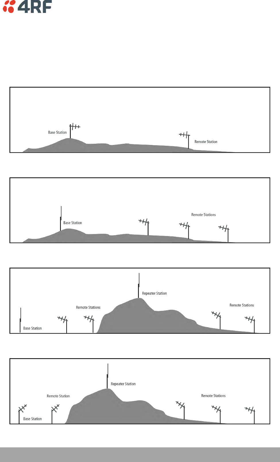
Implementing the Network | 47
Aprisa SR+ User Manual 1.6.0 PO
4. Implementing the Network
Network Topologies
The following are examples of typical network topologies:
Point-To-Point Network
Point-to-Multipoint Network
Point-to-Multipoint with Repeater 1
Point-to-Multipoint with Repeater 2

48 | Implementing the Network
Aprisa SR+ User Manual 1.6.0 PO
Initial Network Deployment
Install the Base Station
To install the base station in your network:
1. Install the base station radio (see ‘Installing the Radio’ on page 58).
2. Set the radio Network ID to a unique ID in your entire network (see ‘Terminal > Device’ on page 88).
3. Set the radio operating mode to ‘base station’ (see ‘Terminal > Operating Mode’ on page 94).
4. Set the radio IP address (see ‘IP > IP Setup > Bridge / Gateway Router Modes’ on page 150).
5. Set the radio frequencies to the frequencies you wish to operate from (see ‘Radio > Radio Setup’ on
page 103).
6. Set the radio security settings (see ‘Security > Setup’ on page 183).
Installing the Remote Stations
To install the remote stations in your network:
1. Install the remote station radio (see ‘Installing the Radio’ on page 58).
2. Set the radio Network ID to the same ID as the other stations in the network (see ‘Terminal > Device’
on page 88).
3. If repeater used in radius 1, set the network radius=2 on all network stations (see ‘Terminal > Device’
on page 88).
4. Set the radio operating mode to ‘remote station’ (see ‘Terminal > Operating Mode’ on page 94).
5. Set the radio IP address (see ‘IP > IP Setup > Bridge / Gateway Router Modes’ on page 150).
6. Set the radio frequencies to the base station / repeater station frequencies you wish to operate from
(see ‘Radio > Radio Setup’ on page 103).
7. Set the radio security settings to the same as the base station (see ‘Security > Setup’ on page 183).
The base station will automatically allocate a node address to the new remote station.
Install a Repeater Station
To install a repeater station in your network:
1. Install the repeater station radio (see ‘Installing the Radio’ on page 58).
2. Set the radio Network ID to the same ID as the other stations in the network (see ‘Terminal > Device’
on page 88).
3. Increase the radio network radius by one on all stations in the network (see ‘Terminal > Device’ on
page 88).
4. Set the radio operating mode to ‘repeater station’ (see ‘Terminal > Operating Mode’ on page 94).
5. Set the radio IP address (see ‘IP > IP Setup > Bridge / Gateway Router Modes’ on page 150).
6. Set the radio frequencies to base station frequencies you wish to operate from (see ‘Radio > Radio
Setup’ on page 103).
7. Set the radio security settings to the same as the base station (see ‘Security > Setup’ on page 183).
The base station will automatically allocate a node address to the new repeater station.

Implementing the Network | 49
Aprisa SR+ User Manual 1.6.0 PO
Network Changes
Adding a Repeater Station
To add a repeater station to your network:
1. Install the repeater station radio (see ‘Installing the Radio’ on page 58).
2. Set the radio Network ID to the same ID as the other stations in the network (see ‘Terminal > Device’
on page 88).
3. Set the radio IP address (see ‘IP > IP Setup > Bridge / Gateway Router Modes’ on page 150).
4. Set the radio frequencies to the base station frequencies you wish to operate from (see ‘Radio > Radio
Setup’ on page 103).
5. Set the radio operating mode to ‘repeater station’ (see ‘Terminal > Operating Mode’ on page 94).
6. Increase the radio network radius by one on all stations in the network (see ‘Terminal > Device’ on
page 88).
The base station will automatically allocate a node address to the new repeater station.
To remove a repeater station from your network:
1. Turn the power off on the remote station radios operating from the repeater station radio you wish to
remove.
2. Turn the power off on the repeater station radio you wish to remove.
3. Decrease the network radius by one on all stations in the network (see ‘Terminal > Device’ on page
88).
Adding a Remote Station
To add a remote station to your network:
1. Install the remote station radio (see ‘Installing the Radio’ on page 58).
2. Set the radio Network ID to the same ID as the other stations in the network (see ‘Terminal > Device’
on page 88).
3. If repeater used in radius 1, set the network radius=2 on all network stations (see ‘Terminal > Device’
on page 88).
4. Set the radio IP address (see ‘IP > IP Setup > Bridge / Gateway Router Modes’ on page 150).
5. Set the radio frequencies to the base station / repeater station frequencies you wish to operate from
(see ‘Radio > Radio Setup’ on page 103).
6. Set the radio operating mode to ‘remote station’ (see ‘Terminal > Operating Mode’ on page 94).
The base station will automatically allocate a node address to the new remote station.
To remove a remote station from your network:
1. Turn the power off on the remote station radio you wish to remove. This is the only action that is
required.
Note: The remote station will continue to show in the Network Table list.
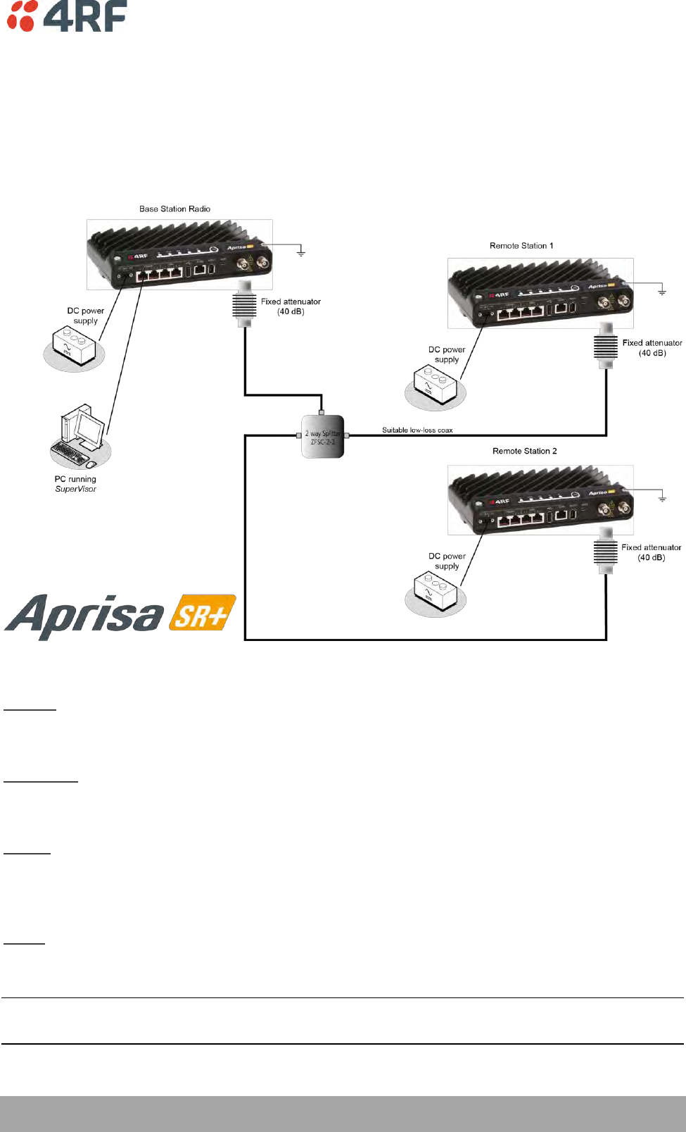
Preparation | 51
Aprisa SR+ User Manual 1.6.0 PO
5. Preparation
Bench Setup
Before installing the links in the field, it is recommended that you bench-test the links. A suggested setup
for basic bench testing is shown below:
When setting up the equipment for bench testing, note the following:
Earthing
Each radio should be earthed at all times. The radio earth point should be connected to a protection
earth.
Attenuators
In a bench setup, there should be 60 - 80 dB at up to 1 GHz of 50 ohm coaxial attenuation, capable of
handling the transmit power of +37 dBm (5 W) between the radios’ antenna connectors.
Splitter
If more than two radios are required in your bench setup, a multi-way splitter is required. The diagram
shows a two way splitter. This splitter should be 50 ohm coaxial up to 1 GHz and capable of handling the
transmit power of +37 dBm (5 W).
Cables
Use double-screened coaxial cable that is suitable for use up to 1 GHz at ≈ 1 metre.
CAUTION: Do not apply signals greater than +10 dBm to the antenna connection as they can damage the
receiver.
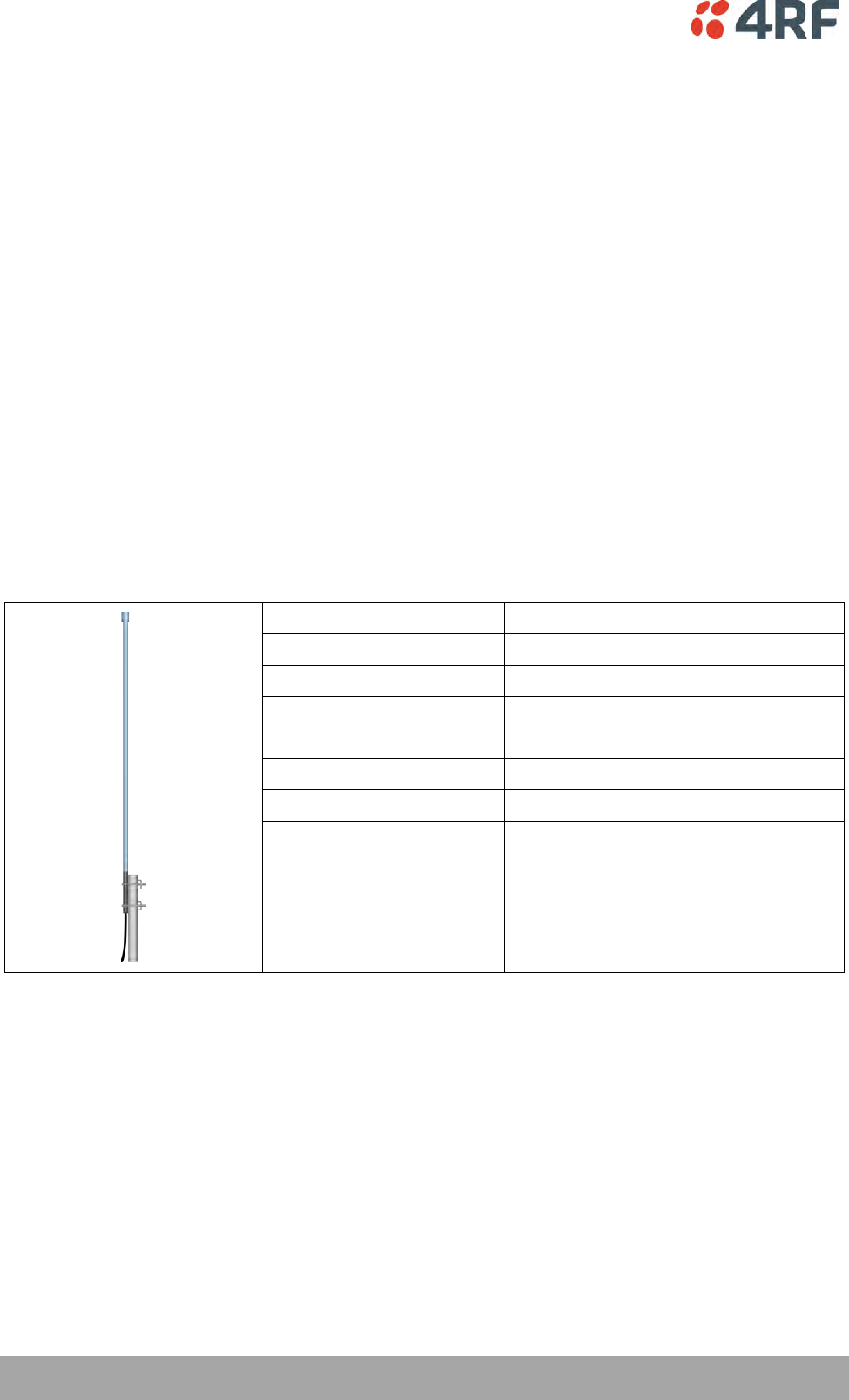
52 | Preparation
Aprisa SR+ User Manual 1.6.0 PO
Path Planning
The following factors should be considered to achieve optimum path planning:
Antenna Selection and Siting
Coaxial Cable Selection
Linking System Plan
Antenna Selection and Siting
Selecting and siting antennas are important considerations in your system design. The antenna choice for
the site is determined primarily by the frequency of operation and the gain required to establish reliable
links.
Base or Repeater Station
The predominant antenna for a base station or a repeater station is an omni-directional collinear gain
antenna.
Omni Directional Collinear Antennas
Factor
Explanation
Frequency
Often used in 380-530 MHz bands
Gain
Varies with size (5 dBi to 8 dBi typical)
Wind loading
Minimal
Tower aperture required
Minimal
Size
Range from 2 m to 3 m length
Polarization
Vertical
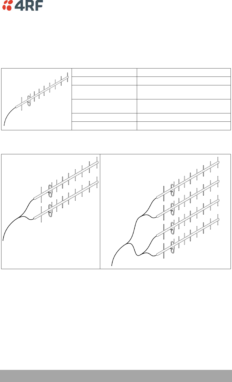
Preparation | 53
Aprisa SR+ User Manual 1.6.0 PO
Remote station
There are two main types of directional antenna that are commonly used for remote stations, Yagi and
corner reflector antennas.
Yagi Antennas
Factor
Explanation
Frequency
Often used in 350-600 MHz bands
Gain
Varies with size (typically 11 dBi to 16
dBi)
Stackable gain increase
2 Yagi antennas (+ 2.8 dB)
4 Yagi antennas (+ 5.6 dB)
Size
Range from 0.6 m to 3 m in length
Front to back ratio
Low (typically 18 to 20 dB)
It is possible to increase the gain of a Yagi antenna installation by placing two or more of them in a stack.
The relative position of the antennas is critical.
Example of stacked antennas
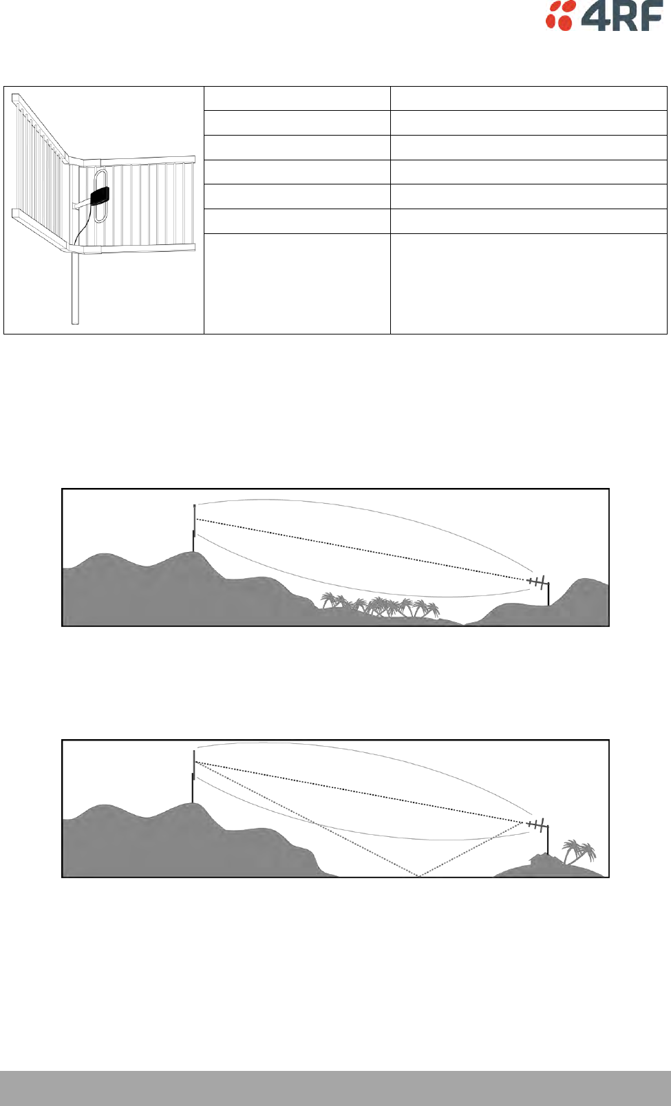
54 | Preparation
Aprisa SR+ User Manual 1.6.0 PO
Corner Reflector Antennas
Factor
Explanation
Frequency
Often used in 330-960 MHz bands
Gain
Typically 12 dBi
Size
Range from 0.36 m to 0.75 m in length
Front to back ratio
High (typically 30 dB)
Beamwidth
Broad (up to 60°)
Antenna Siting
When siting antennas, consider the following points:
A site with a clear line of sight to the remote radio is recommended. Pay particular attention to trees,
buildings, and other obstructions close to the antenna site.
Example of a clear line-of-sight path
Any large flat areas that reflect RF energy along the link path, for instance, water, could cause multipath
fading. If the link path crosses a feature that is likely to cause RF reflections, shield the antenna from the
reflected signals by positioning it on the far side of the roof of the equipment shelter or other structure.
Example of a mid-path reflection path
The antenna site should be as far as possible from other potential sources of RF interference such as
electrical equipment, power lines and roads. The antenna site should be as close as possible to the
equipment shelter.
Wide angle and zoom photographs taken at the proposed antenna location (looking down the proposed
path), can be useful when considering the best mounting positions.
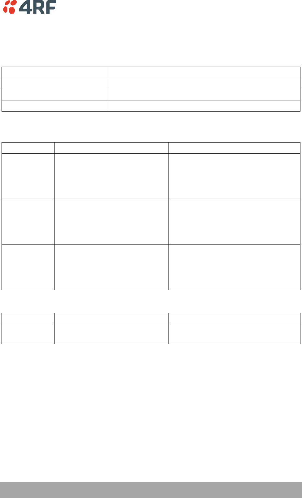
Preparation | 55
Aprisa SR+ User Manual 1.6.0 PO
Coaxial Feeder Cables
To ensure maximum performance, it is recommended that you use good quality low-loss coaxial cable for
all feeder runs. When selecting a coaxial cable consider the following:
Factor
Effect
Attenuation
Short cables and larger diameter cables have less attenuation
Cost
Smaller diameter cables are cheaper
Ease of installation
Easier with smaller diameter cables or short cables
For installations requiring long feeder cable runs, use the RFI AVA5 50, RFI LDF4 50A or RFI CNT-400 feeder
cable or equivalent:
Part Number
Part Description
Specification
RFI AVA5 50
Feeder Cable, 7/8", HELIAX, Low loss
7/8" foam dielectric. Standard Jacket
Outer conductor corrugated copper, inner
conductor copper-clad aluminum
Bending radius of 250 mm min
Attenuation of 2.65 dB / 100m @ 520 MHz
RFI LDF4 50A
Feeder cable, 1/2", HELIAX, Loss Loss
1/2" foam dielectric. Standard Jacket
Outer conductor corrugated copper, inner
conductor copper-clad aluminum
Bending radius of 125 mm min
Attenuation of 5.1 dB / 100m @ 520 MHz
RFI CNT 400
Feeder, CNT-400, 10.8mm, Double
Shielded Solid Polyethylene
Low loss 0.4’ (10.8 mm) feeder cable
UV protected black Polyethylene, bonded
AL tape outer conductor
Bending radius of 30 mm min
Attenuation of 8.8 dB / 100m @ 450 MHz
For installations requiring short feeder cable runs, use the RFI 8223 feeder cable or equivalent:
Part Number
Part Description
Specification
RFI 8223
Feeder, RG 223 5.4mm d, Double
Shielded Solid Polyethylene
Bending radius of 20 mm min
Attenuation of 30.5 dB / 100m @ 450 MHz
When running cables:
Run coaxial feeder cable from the installation to the antenna, ensuring you leave enough extra cable at
each end to allow drip loops to be formed.
Terminate and ground the feeder cables in accordance with the manufacturers’ instructions. Bond the
outer conductor of the coaxial feeder cables to the base of the tower mast.
Linking System Plan
All of the above factors combine in any proposed installation to create a Linking System Plan. The Linking
System Plan predicts how well the radios will perform after it is installed.
Use the outputs of the Linking System Plan during commissioning to confirm the radios have been installed
correctly and that it will provide reliable service.
56 | Preparation
Aprisa SR+ User Manual 1.6.0 PO
Site Requirements
Power Supply
Ensure a suitable power supply is available for powering the radio.
The nominal input voltage for a radio is +13.8 VDC (negative earth) with an input voltage range of +10 to
+30 VDC. The maximum power input is 35 W.
WARNING:
Before connecting power to the radio, ensure that the radio is grounded via the
negative terminal of the DC power connection.
Equipment Cooling
If the Aprisa SR+ is operated in an environment where the ambient temperature exceeds 50°C, the Aprisa
SR+ convection air flow over the heat sinks must be considered.
The environmental operating conditions are as follows:
Operating temperature
-40 to +70˚ C
Storage temperature
-40 to +80˚ C
Humidity
Maximum 95% non-condensing
WARNING:
If the Aprisa SR+ is operated in an environment where the ambient temperature
exceeds 50°C, the Aprisa SR+ must be installed within a restricted access location to
prevent human contact with the enclosure heat sink.
WARNING:
The Aprisa SR+ can be operated in an environment where the ambient temperature
exceeds 50°C. The heat sink will be a hot surface - do not touch.
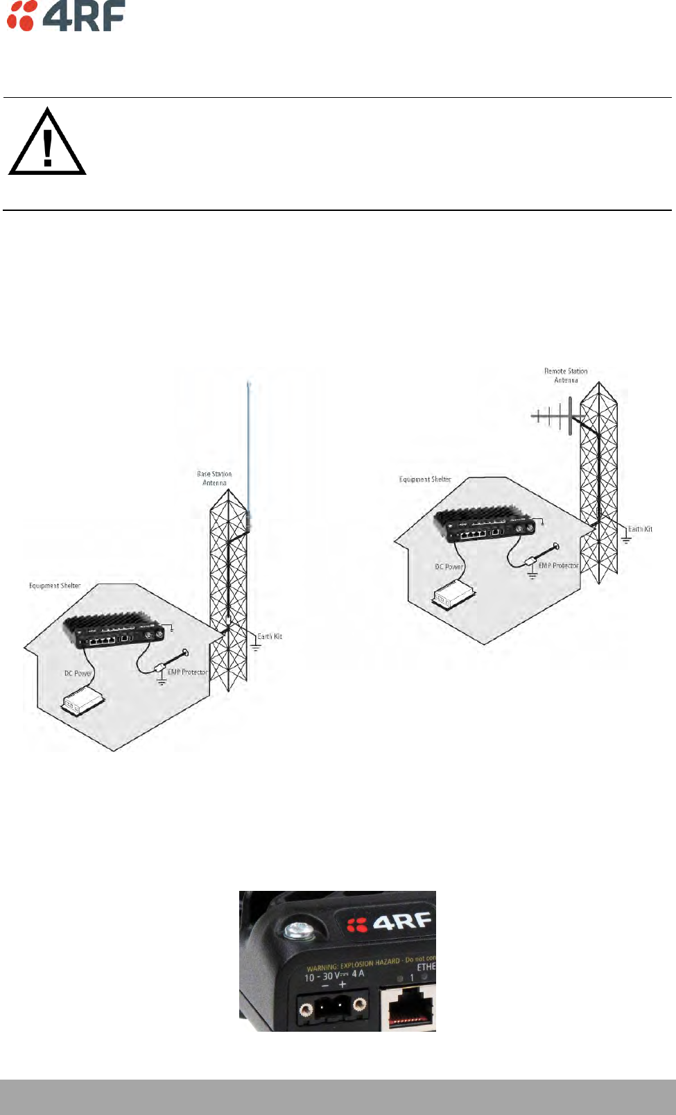
Preparation | 57
Aprisa SR+ User Manual 1.6.0 PO
Earthing and Lightning Protection
WARNING:
Lightning can easily damage electronic equipment.
To avoid this risk, install primary lightning protection devices on any interfaces that
are reticulated in the local cable network.
You should also install a coaxial surge suppressor on the radio antenna port.
Feeder Earthing
Earth the antenna tower, feeders and lightning protection devices in accordance with the appropriate
local and national standards. The diagram below shows the minimum requirements.
Use grounding kits as specified or supplied by the coaxial cable manufacturer to properly ground or bond
the cable outer.
Radio Earthing
The Aprisa SR+ has an earth connection point on the top left and the top right of the enclosure. M4 8mm
pan pozi machine screws and M4 lock washers are supplied fitted to the radio. These screws can be used
to earth the enclosure to a protection earth.
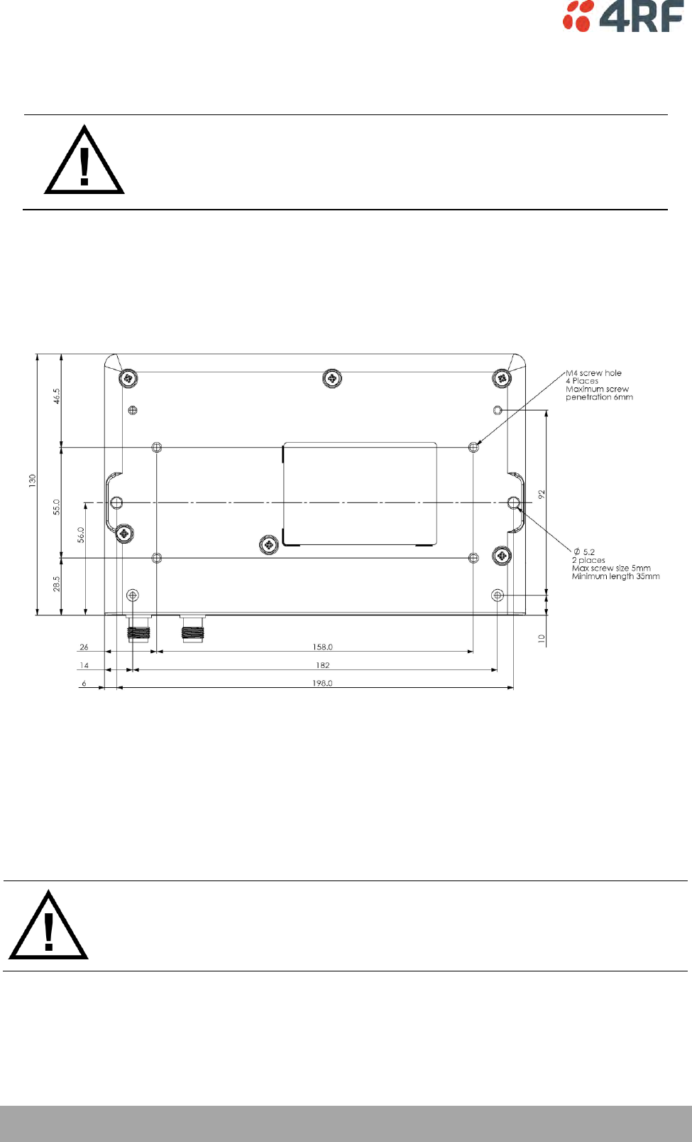
58 | Installing the Radio
Aprisa SR+ User Manual 1.6.0 PO
6. Installing the Radio
CAUTION:
You must comply with the safety precautions in this manual or on the product
itself.
4RF does not assume any liability for failure to comply with these precautions.
Mounting
The Aprisa SR+ has four threaded holes (M4) in the enclosure base and two holes (5.2 mm) through the
enclosure for mounting.
Mounting options include:
DIN rail mounting with the Aprisa SR+ DIN Rail Mounting Bracket
Rack shelf mounting
Wall mounting
Outdoor enclosure mounting
WARNING:
If the Aprisa SR+ is operated in an environment where the ambient temperature
exceeds 50°C, the Aprisa SR+ must be installed within a restricted access location to
prevent human contact with the enclosure heatsink.
Required Tools
No special tools are needed to install the radio.
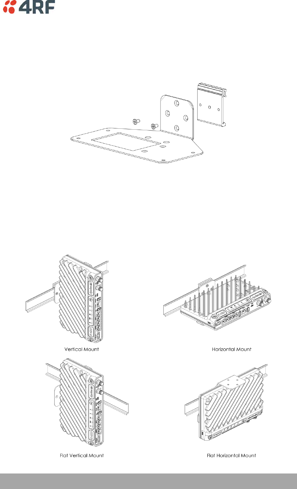
Installing the Radio | 59
Aprisa SR+ User Manual 1.6.0 PO
DIN Rail Mounting
The Aprisa SR+ has an optional accessory part to enable the mounting on a standard DIN rail:
Part Number
Part Description
APSB-MBRK-DIN
4RF SR+ Acc, Mounting, Bracket, DIN Rail
The Aprisa SR+ is mounted into the DIN rail mounting bracket using the four M4 threaded holes in the
Aprisa SR+ enclosure base. Four 8 mm M4 pan pozi machine screws are supplied with the bracket.
The Aprisa SR+ DIN rail mounting bracket can be mounted in four positions on a horizontal DIN rail:
Vertical Mount (vertical enclosure perpendicular to the mount)
Horizontal Mount (horizontal enclosure perpendicular to the mount)
Flat Vertical Mount (vertical enclosure parallel to the mount)
Flat Horizontal Mount (horizontal enclosure parallel to the mount)
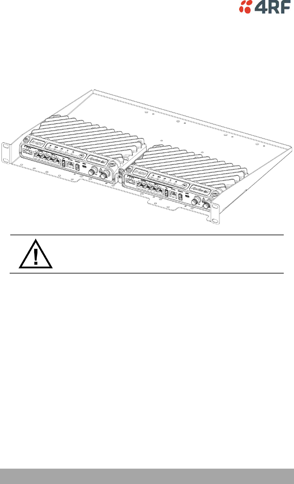
60 | Installing the Radio
Aprisa SR+ User Manual 1.6.0 PO
Rack Shelf Mounting
The Aprisa SR+ can be mounted on a rack mount shelf using the four M4 threaded holes in the Aprisa SR+
enclosure base. The following picture shows Aprisa SR+ mounted on a 1 RU rack mounted shelf.
Part Number
Part Description
APSB-MR19-X1U
4RF SR+ Acc, Mounting, 19" Rack Mount Shelf, 1U
WARNING:
If the Aprisa SR+ is operated in an environment where the ambient temperature
exceeds 50°C, the Aprisa SR+ convection air flow over the heat sinks must be
considered.
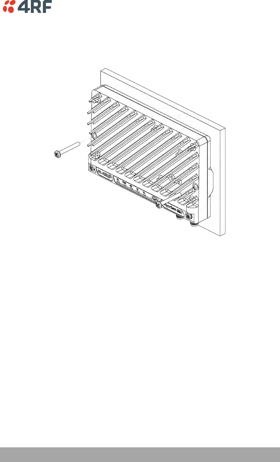
Installing the Radio | 61
Aprisa SR+ User Manual 1.6.0 PO
Wall Mounting
The Aprisa SR+ can be mounted on a wall using the two holes through the enclosure (5.2 mm diameter).
Typically, M5 screws longer than 35 mm would be used.
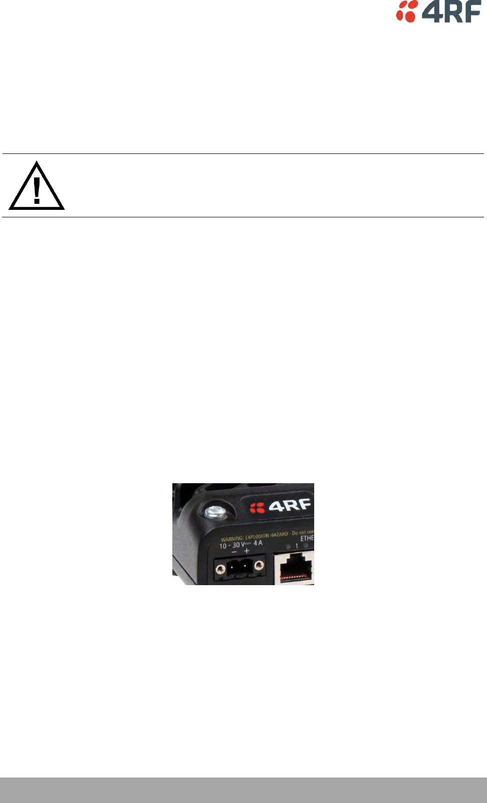
62 | Installing the Radio
Aprisa SR+ User Manual 1.6.0 PO
Installing the Antenna and Feeder Cable
Carefully mount the antenna following the antenna manufacturers’ instructions. Run feeder cable from
the antenna to the radio location.
Lightning protection must be incorporated into the antenna system (see ‘Earthing and Lightning
Protection’ on page 57).
WARNING:
When the link is operating, there is RF energy radiated from the antenna.
Do not stand in front of the antenna while the radio is operating (see the ‘RF
Exposure Warning’ on page 3).
Fit the appropriate male or female connector (usually N-type) to the antenna feeder at the antenna end.
Carefully follow the connector manufacturers’ instructions.
Securely attach the feeder cable to the mast and cable trays using cable ties or cable hangers. Follow the
cable manufacturer’s recommendations about the use of feeder clips, and their recommended spacing.
Connect the antenna and feeder cable. Weatherproof the connection with a boot, tape or other approved
method.
The Aprisa SR+ antenna connection is a TNC female connector so the feeder / jumper must be fitted with
a TNC male connector.
If a jumper is used between the feeder and the radio, connect a coaxial surge suppressor or similar
lightning protector between the feeder and jumper cables (or at the point where the cable enters the
equipment shelter). Connect the feeder cable to the antenna port on the radio.
Earth the case of the lightning protector to the site Lightning Protection Earth.
The Aprisa SR+ has an earth connection point on the top left and the top right of the enclosure. M4 8mm
pan pozi machine screws and M4 lock washers are supplied fitted to the radio. These screws can be used
to earth the enclosure to a protection earth.

Installing the Radio | 63
Aprisa SR+ User Manual 1.6.0 PO
Connecting the Power Supply
The nominal input voltage for a radio is +13.8 VDC (negative earth) with an input voltage range of +10 to
+30 VDC. The maximum power input is 35 W.
The power connector required is a Molex 2 pin female screw fitting part. This connector is supplied fitted
to the radio.
The negative supply of the Aprisa SR+ power connection is internally connected to the Aprisa SR+
enclosure. Power must be supplied from a Negative Earthed power supply.
Wire your power source to power connector and plug the connector into the radio. The connector screws
can be fastened to secure the connector.
Spare Molex 2 pin female power connectors can be ordered from 4RF:
Part Number
Part Description
APST-CML2-FEM-01
4RF SR+ Spare, Connector, Molex 2 pin, Female, 1 item
Turn your power source on:
All the radio LEDs will flash orange for one second and then the OK, MODE and AUX LEDs will light
green, the TX and RX LEDs will flash red.
The Aprisa SR+ radio is ready to operate
The TX and RX LEDs will be green (steady or flashing) when the radio is registered with the
network.
If the LEDs fail to light, carefully check the supply polarity. If the power supply connections have been
accidentally reversed, internal fuses will have blown to protect the unit.
Spare fuses are contained within the radio, see ‘Spare Fuses’ on page 64 for instructions on how to locate
and replace the fuses.
External Power Supplies
The following external power supplies are available from 4RF as accessories:
Part Number
Part Description
APSB-P230-030-24-TS
4RF SR+ Acc, PSU, 230 VAC, 30W, 24 VDC, -10 to +60C
APSB-P230-048-24-TE
4RF SR+ Acc, PSU, 230 VAC, 48W, 24 VDC, -20 to +75C
APSB-P230-060-24-TS
4RF SR+ Acc, PSU, 230 VAC, 60W, 24 VDC, -10 to +60C
APSB-P48D-050-24-TA
4RF SR+ Acc, PSU, 48 VDC, 50W, 24 VDC, 0 to +50C
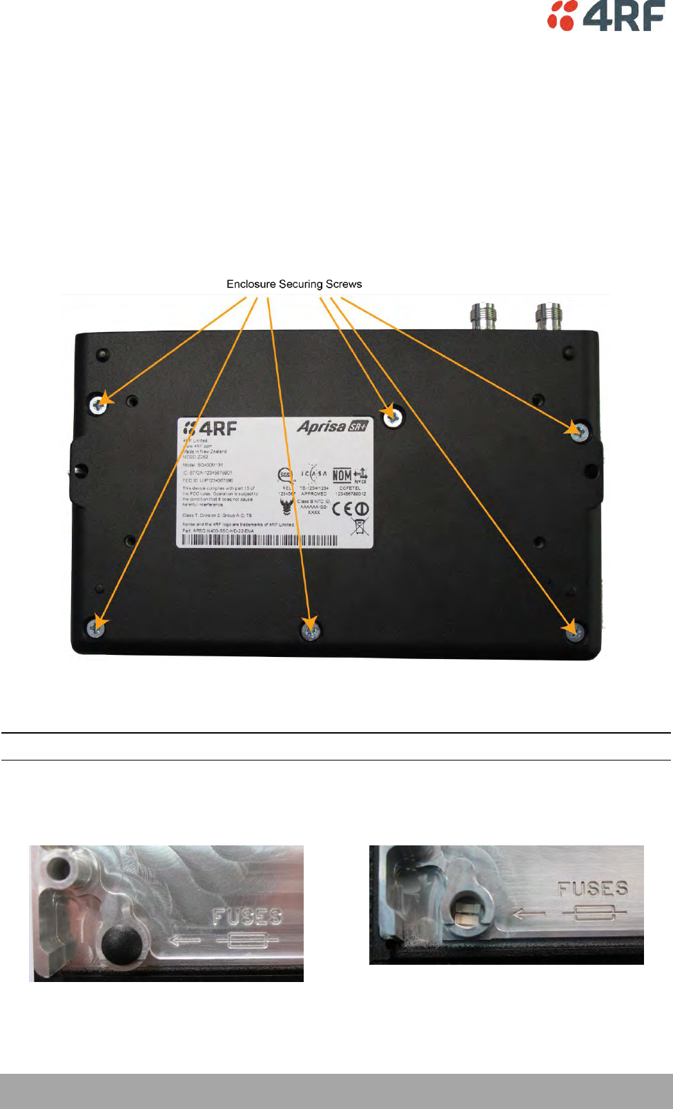
64 | Installing the Radio
Aprisa SR+ User Manual 1.6.0 PO
Spare Fuses
The Aprisa SR+ PBA contains two fuses in the power input with designators F1 and F2. Both the positive
and negative power connections are fused. The fuse type is a Littelfuse 0454007 with a rating of 7 A, 75 V,
very fast acting.
To replace the fuses:
1. Remove the input power and antenna cable.
2. Unscrew the enclosure securing screws (posi 2).
2. Separate the enclosure halves.
CAUTION: Antistatic precautions must be taken as the internal components are static sensitive.
3. Access the enclosure spare fuses under the plastic cap.
Installing the Radio | 65
Aprisa SR+ User Manual 1.6.0 PO
4. Replace the two fuses.
5. Close the enclosure and tighten the screws.
Note: Is it critical that the screws are re-tightened to 1.2 Nm. The transmitter adjacent channel
performance can be degraded if the screws are not tightened correctly.
Additional Spare Fuses
Additional spare fuses can be ordered from 4RF:
Part Number
Part Description
APST-FNAN-454-07-02
4RF SR+ Spare, Fuse, Nano SMF, 454 Series, 7A, 2 items

Managing the Radio | 67
Aprisa SR+ User Manual 1.6.0 PO
7. Managing the Radio
SuperVisor
The Aprisa SR+ contains an embedded web server application (SuperVisor) to enable element management
with any major web browser (such as Mozilla Firefox or Microsoft® Internet Explorer).
SuperVisor enables operators to configure and manage the Aprisa SR+ base station radio and repeater /
remote station radios over the radio link.
The key features of SuperVisor are:
Full element management, configuration and diagnostics
Manage the entire network from the Base Station (remote management of elements)
Managed network software distribution and upgrades
Performance and alarm monitoring of the entire network, including RSSI, alarm states, time-
stamped events, etc.
View and set standard radio configuration parameters including frequencies, transmit power,
channel access, serial, Ethernet port settings
Set and view security parameters
User management
Operates over a secure HTTPS session on the access connection to the base station

68 | Managing the Radio
Aprisa SR+ User Manual 1.6.0 PO
PC Requirements for SuperVisor
SuperVisor requires the following minimum PC requirements:
Browser
Operating System
Processor
RAM
Internet Explorer 7
(oldest browser supported)
IE7 can operate with less but will be
very slow.
MS-Windows XP
Service Pack 2
1 GHz processor
1 GB Ram
Internet Explorer 9
Does not support config file upload
from PC
MS-Windows Vista
Service Pack 2
1 GHz processor
2 GB Ram
Internet Explorer 10
(recommended minimum browser)
MS-Windows 7
Service Pack 1
1 GHz processor
2 GB Ram
Internet Explorer 11
MS-Windows 8.1
1 GHz processor
2 GB Ram
Mozilla Firefox (MS-Windows)
MS-Windows XP
Service Pack 2
1 GHz processor,
Pentium 4 and above
1 GB Ram
Mozilla Firefox (Linux)
Gnome desktop 2.18 and above
1 GHz processor,
Pentium 4 and above
1 GB Ram
Mozilla Firefox (Apple Mac)
(4RF does not support retina displays)
Mac OS X 10.6
1 GHz processor,
Pentium 4 and above
1 GB Ram
Note: 4RF does not support Google Chrome, Opera browser or Apple Safari but when they have been used
they have worked correctly.

Managing the Radio | 69
Aprisa SR+ User Manual 1.6.0 PO
Connecting to SuperVisor
The predominant management connection to the Aprisa SR+ radio is with an Ethernet interface using
standard IP networking. There should be only one Ethernet connection from the base station to the
management network.
The Aprisa SR+ has a factory default IP address of 169.254.50.10 with a subnet mask of 255.255.0.0. This is
an IPv4 Link Local (RFC3927) address which simplifies the connection to a PC.
Each radio in the network must be set up with a unique IP address on the same subnet.
The Aprisa SR+ Protected Station radio A (left radio) has a factory default IP address of 169.254.50.10 and
radio B (right radio) has a factory default IP address of 169.254.50.20, both with a subnet mask of
255.255.0.0.
To change the Aprisa SR+ IP address:
1. Set up your PC for a compatible IP address e.g. 169.254.50.1 with a subnet mask of 255.255.0.0.
2. Connect your PC network port to one of the Aprisa SR+ Ethernet ports.
3. Open a browser and enter https://169.254.50.10.
4. Login to the radio with the default Username ‘admin’ and Password ‘admin’.
5. Change the IP address to conform to the network plan in use.
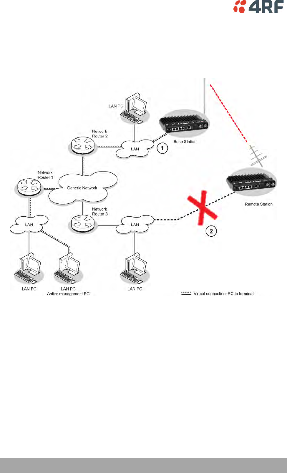
70 | Managing the Radio
Aprisa SR+ User Manual 1.6.0 PO
Management PC Connection
The active management PC must only have one connection to the network as shown by path . There
should not be any alternate path that the active management PC can use via an alternate router or
alternate LAN that would allow the management traffic to be looped as shown by path .
When logging into a network, it is important to understand the relationship between the Local Radio and
the Remote Radios.
The Local Radio is the radio that your IP network is physically connected to.
If the Local Radio is a base station, SuperVisor manages the base station and all the repeater stations and
remote stations in the network.
If the Local Radio is a remote station or repeater station, SuperVisor only manages the remote / repeater
station radio logged into.
If the user is at the remote station and connects SuperVisor directly to the remote radio via their
computer, all relevant features are still available. This includes the ability to monitor the ‘Last received
packet RSSI. If ICMP is enabled on the base station, the user will also be able to ping the base station to
confirm the connectivity.
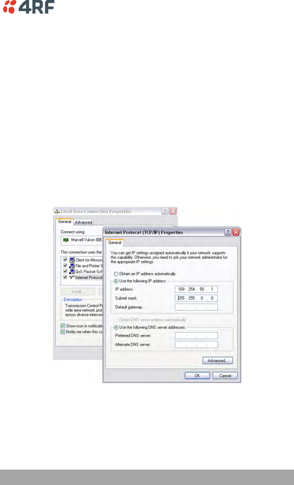
Managing the Radio | 71
Aprisa SR+ User Manual 1.6.0 PO
PC Settings for SuperVisor
To change the PC IP address:
If your PC has previously been used for other applications, you may need to change the IP address and the
subnet mask settings. You will require Administrator rights on your PC to change these.
Windows XP example:
1. Open the ‘Control Panel’.
2. Open ‘Network Connections’ and right click on the ‘Local Area Connection’ and select ‘Properties’.
3. Click on the ‘General’ tab.
4. Click on ‘Internet Protocol (TCP/IP)’ and click on properties.
5. Enter the IP address and the subnet mask (example as shown).
6. Click ‘OK’ then close the Control Panel.
If the radio is on a different subnet from the network the PC is on, set the PC default gateway address to
the network gateway address which is the address of the router used to connect the subnets (for details,
consult your network administrator).
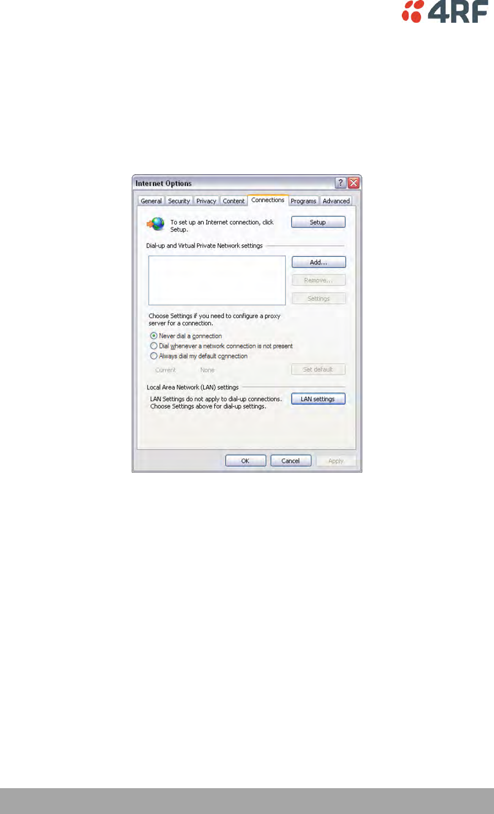
72 | Managing the Radio
Aprisa SR+ User Manual 1.6.0 PO
To change the PC connection type:
If your PC has previously been used with Dial-up connections, you may need to change your PC Internet
Connection setting to ‘Never dial a connection’.
Windows Internet Explorer 8 example:
1. Open Internet Explorer.
2. Open the menu item Tools > Internet Options and click on the ‘Connections’ tab.
3. Click the ‘Never dial a connection’ option.
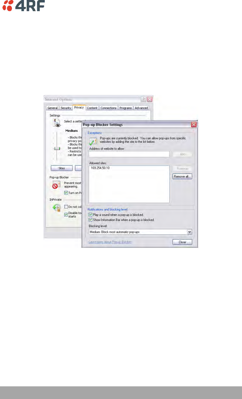
Managing the Radio | 73
Aprisa SR+ User Manual 1.6.0 PO
To change the PC pop-up status:
Some functions within SuperVisor require Pop-ups enabled e.g. saving a MIB
Windows Internet Explorer 8 example:
1. Open Internet Explorer.
2. Open the menu item Tools > Internet Options and click on the ‘Privacy’ tab.
3. Click on ‘Pop-up Blocker Settings’.
4. Set the ‘Address of Web site to allow’ to the radio address or set the ‘Blocking Level’ to ‘Low: Allow
Pop-ups from secure sites’ and close the window.
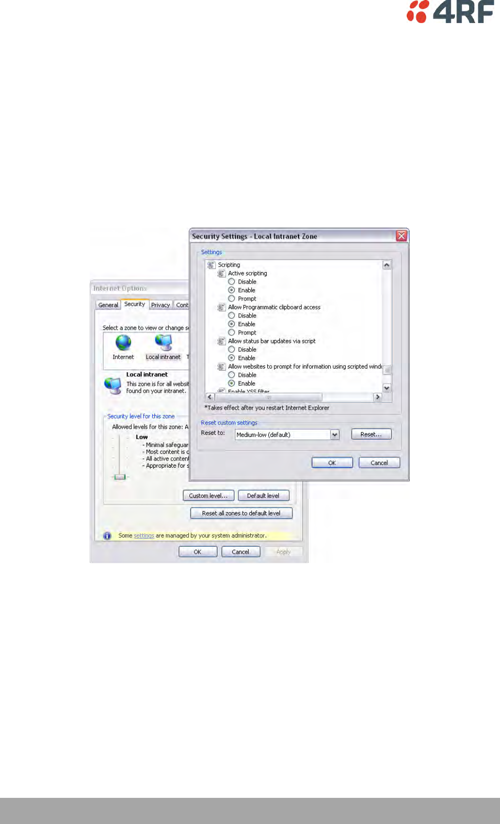
74 | Managing the Radio
Aprisa SR+ User Manual 1.6.0 PO
To enable JavaScript in the web browser:
Some functions within SuperVisor require JavaScript in the web browser to be enabled.
Windows Internet Explorer 8 example:
1. Open Internet Explorer.
2. Open the menu item Tools > Internet Options and click on the ‘Security’ tab.
3. Click on ‘Local Intranet’.
4. Click on ‘Custom Level’.
5. Scroll down until you see section labeled ‘Scripting’.
6. Under ‘Active Scripting’, select ‘Enable’.
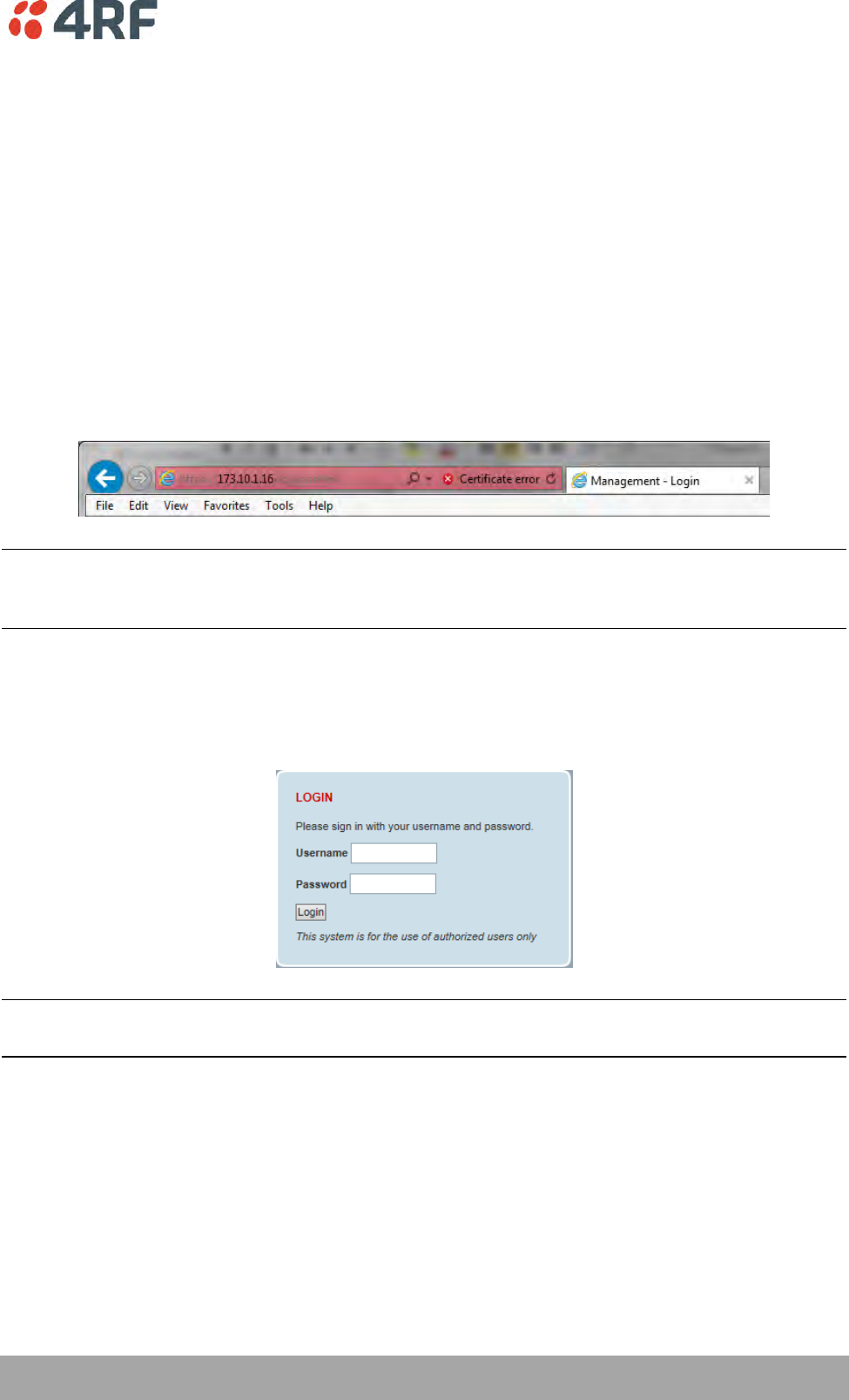
Managing the Radio | 75
Aprisa SR+ User Manual 1.6.0 PO
Login to SuperVisor
The maximum number of concurrent users that can be logged into a radio is 6.
If SuperVisor is inactive for a period defined by the Inactivity Timeout option (see ‘Maintenance > General’
on page 208), the radio will automatically logout the user.
To login to SuperVisor:
1. Open your web browser and enter the IP address of the radio.
If you haven’t assigned an IP address to the radio, use the factory default IP address of 169.254.50.10 with
a subnet mask of 255.255.0.0.
If you don’t know the IP address of the radio, you can determine it using the Command Line Interface (see
‘Command Line Interface’ on page 322).
Note: The Aprisa SR+ has a randomly generated unique self-signed ECC256 security certificate which may
cause the browser to prompt a certificate warning. It is safe to ignore the warning and continue. The valid
certificate is ‘Issued By: 4RF-APRISA’ which can be viewed in the browser.
2. Login with the Username and Password assigned to you.
If unique usernames and passwords have not yet been configured, use the default username ‘admin’ and
password ‘admin’.
Important: After you login for the very first time, it is recommended that you change the default admin
password for security reasons (see ‘Changing Passwords’ on page 192).
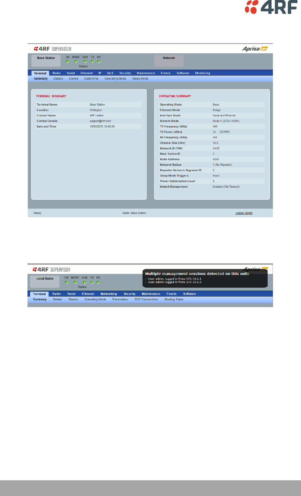
76 | Managing the Radio
Aprisa SR+ User Manual 1.6.0 PO
If the login is successful, the opening page will be displayed.
If there is more than one user logged into the same radio, the Multiple Management Sessions popup will
show the usernames and IP addresses of the users. This popup message will display until 5 seconds after
the cursor is moved. The event log will also record the users logged into the radio or logged out the radio.
Logout of SuperVisor
As the maximum number of concurrent users that can be logged into a radio is 6, not logging out correctly
can restrict access to the radio until after the timeout period (30 minutes).
Logging out from a radio will logout all users logged in with the same username.
If the SuperVisor window is closed without logging out, the radio will automatically log the user out after a
timeout period of 3 minutes.
To logout of SuperVisor:
Click on the ‘Logout’ button on the Summary Bar.
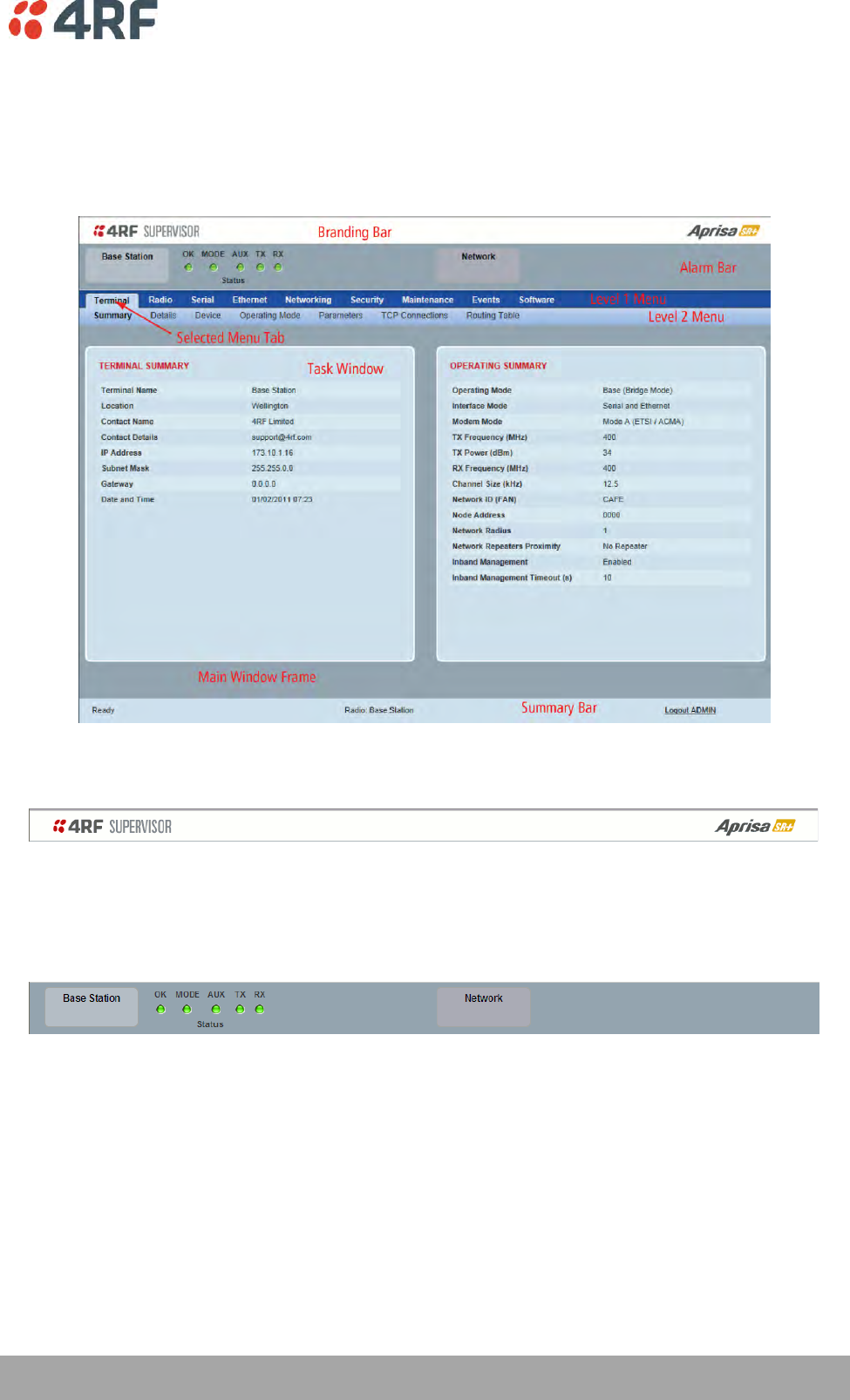
Managing the Radio | 77
Aprisa SR+ User Manual 1.6.0 PO
SuperVisor Page Layout
Standard Radio
The following shows the components of the SuperVisor page layout for a standard radio:
SuperVisor Branding Bar
The branding bar at the top of the SuperVisor frame shows the branding of SuperVisor on the left and the
product branding on the right.
SuperVisor Alarm Bar
The alarm bar shows the name of the radio terminal that SuperVisor is logged into (the local radio) on the
left.
If the local radio is a base station, the page shows the name of the current remote / repeater station (the
remote radio) on the right. SuperVisor will manage all the repeater stations and remote stations in the
network.
If the local radio is a remote station or repeater station, the page shows the name of the remote /
repeater station on the left. The right side of the Alarm Bar will be blank. SuperVisor manages only the
remote / repeater station logged into.
The LED alarm indicators reflect the status of the front panel LEDs on the radio.
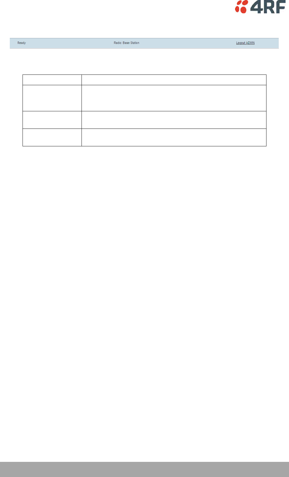
78 | Managing the Radio
Aprisa SR+ User Manual 1.6.0 PO
SuperVisor Summary Bar
The summary bar at the bottom of the page shows:
Position
Function
Left
Busy - SuperVisor is busy retrieving data from the radio that
SuperVisor is logged into.
Ready - SuperVisor is ready to manage the radio.
Middle
Displays the name of the radio terminal that SuperVisor is currently
managing.
Right
The access level logged into SuperVisor. This label also doubles as
the SuperVisor logout button.

Managing the Radio | 79
Aprisa SR+ User Manual 1.6.0 PO
SuperVisor Menu
The following is a list of SuperVisor top level menu items:
Local Terminal
Network
Network Table
Terminal
Summary
Radio
Exceptions
Serial
View
Ethernet
IP
QoS
Security
Maintenance
Events
Software
Monitoring
SuperVisor Parameter Settings
Changes to parameters settings have no effect until the ‘Save’ button is clicked.
Click the ‘Save’ button to apply the changes or ‘Cancel’ button to restore the current value.

80 | Managing the Radio
Aprisa SR+ User Manual 1.6.0 PO
SuperVisor Menu Access
The SuperVisor menu has varying access levels dependent on the login User Privileges.
The following is a list of all possible SuperVisor menu items versus user privileges:
Terminal Settings Menu Items
Menu Item
View
Technician
Engineer
Admin
Terminal > Summary
Read-Only
Read-Only
Read-Only
Read-Only
Terminal > Details
Read-Only
Read-Only
Read-Only
Read-Only
Terminal > Device
No Access
Read-Write
Read-Write
Read-Write
Terminal > Date / Time
Read-Only
Read-Only
Read-Only
Read-Only
Terminal > Operating Mode
No Access
Read-Write
Read-Write
Read-Write
Terminal > Sleep Mode
No Access
Read-Write
Read-Write
Read-Write
Radio > Radio Summary
Read-Only
Read-Only
Read-Only
Read-Only
Radio > Channel Summary
Read-Only
Read-Only
Read-Only
Read-Only
Radio > Radio Setup
No Access
Read-Write
Read-Write
Read-Write
Radio > Channel Setup
No Access
Read-Write
Read-Write
Read-Write
Radio > Advanced Setup
No Access
Read-Write
Read-Write
Read-Write
Serial > Summary
Read-Only
Read-Only
Read-Only
Read-Only
Serial > Port Setup
No Access
Read-Write
Read-Write
Read-Write
Ethernet > Summary
Read-Only
Read-Only
Read-Only
Read-Only
Ethernet > Port Setup
No Access
Read-Write
Read-Write
Read-Write
Ethernet > L2 Filtering
No Access
No Access
Read-Write
Read-Write
Ethernet > VLAN
No Access
No Access
Read-Write
Read-Write
IP > IP Summary
Read-Only
Read-Only
Read-Only
Read-Only
IP > Terminal Server Summary
Read-Only
Read-Only
Read-Only
Read-Only
IP > IP Setup
No Access
Read-Write
Read-Write
Read-Write
IP > Terminal Server Setup
No Access
Read-Write
Read-Write
Read-Write
IP > L3 Filtering
No Access
No Access
Read-Write
Read-Write
IP > IP Routes
No Access
No Access
Read-Write
Read-Write
QoS > Summary
Read-Only
Read-Only
Read-Only
Read-Only
QoS > Traffic Priority
No Access
No Access
Read-Write
Read-Write
QoS > Traffic Classification
No Access
No Access
Read-Write
Read-Write
Security > Summary
Read-Only
Read-Only
Read-Only
Read-Only
Security > Setup
No Access
No Access
Read-Write
Read-Write
Security > Users
No Access
No Access
No Access
Read-Write
Security > RADIUS
No Access
No Access
No Access
Read-Write
Security > SNMP
No Access
No Access
No Access
Read-Write
Security > Manager
No Access
No Access
Read-Write
Read-Write
Security > Distribution
No Access
No Access
Read-Write
Read-Write
Maintenance > Summary
Read-Only
Read-Only
Read-Only
Read-Only
Maintenance > General
No Access
Read-Write
Read-Write
Read-Write
Maintenance > Test Mode
No Access
Read-Write
Read-Write
Read-Write

Managing the Radio | 81
Aprisa SR+ User Manual 1.6.0 PO
Menu Item
View
Technician
Engineer
Admin
Maintenance > Defaults
No Access
No Access
No Access
Read-Write
Maintenance > Protection
No Access
Read-Write
Read-Write
Read-Write
Maintenance > Licence
No Access
No Access
Read-Write
Read-Write
Maintenance > SCADA
No Access
No Access
Read-Write
Read-Write
Maintenance > MMS
No Access
No Access
Read-Write
Read-Write
Maintenance > Advanced
No Access
No Access
Read-Write
Read-Write
Events > Alarm Summary
Read-Only
Read-Only
Read-Only
Read-Only
Events > Event History
Read-Only
Read-Only
Read-Only
Read-Only
Events > Event Primary History
Read-Only
Read-Only
Read-Only
Read-Only
Events > Event Secondary History
Read-Only
Read-Only
Read-Only
Read-Only
Events > Events Setup
No Access
No Access
Read-Write
Read-Write
Events > Traps Setup
No Access
No Access
Read-Write
Read-Write
Events > Alarm I/O Setup
Read-Only
Read-Only
Read-Write
Read-Write
Events > Event Action Setup
No Access
No Access
Read-Write
Read-Write
Events > Defaults
No Access
No Access
Read-Write
Read-Write
Software > Summary
Read-Only
Read-Only
Read-Only
Read-Only
Software > Setup
No Access
No Access
Read-Write
Read-Write
Software > File Transfer
No Access
No Access
Read-Write
Read-Write
Software > File Primary Transfer
No Access
No Access
Read-Write
Read-Write
Software > File Secondary Transfer
No Access
No Access
Read-Write
Read-Write
Software > Manager
No Access
No Access
Read-Write
Read-Write
Software > Remote Distribution
No Access
No Access
Read-Write
Read-Write
Software > Remote Activation
No Access
No Access
Read-Write
Read-Write
Monitoring > Terminal
Read-Only
Read-Only
Read-Only
Read-Only
Monitoring > Serial
Read-Only
Read-Only
Read-Only
Read-Only
Monitoring > Ethernet
Read-Only
Read-Only
Read-Only
Read-Only
Monitoring > Radio
Read-Only
Read-Only
Read-Only
Read-Only
Monitoring > User Selected
Read-Only
Read-Only
Read-Only
Read-Only
Monitoring > TCP Connections
Read-Only
Read-Only
Read-Only
Read-Only
Monitoring > Routing Table
Read-Only
Read-Only
Read-Only
Read-Only
Monitoring > Address Tables
Read-Only
Read-Only
Read-Only
Read-Only
Monitoring > SCADA
Read-Only
Read-Only
Read-Only
Read-Only
Network Settings Menu Items
Menu Item
View
Technician
Engineer
Admin
Network Table
Read-Only
Read-Only
Read-Only
Read-Only
Summary
Read-Only
Read-Only
Read-Only
Read-Only
Exceptions
Read-Only
Read-Only
Read-Only
Read-Only
View
Read-Only
Read-Only
Read-Only
Read-Only

82 | Managing the Radio
Aprisa SR+ User Manual 1.6.0 PO
SuperVisor Menu Items
As SuperVisor screens are dependent on the Aprisa SR+ configuration deployed, the following section is
split into two sections:
Standard Radio
Protected Station
All SuperVisor menu item descriptions assume full access ‘Admin’ user privileges:
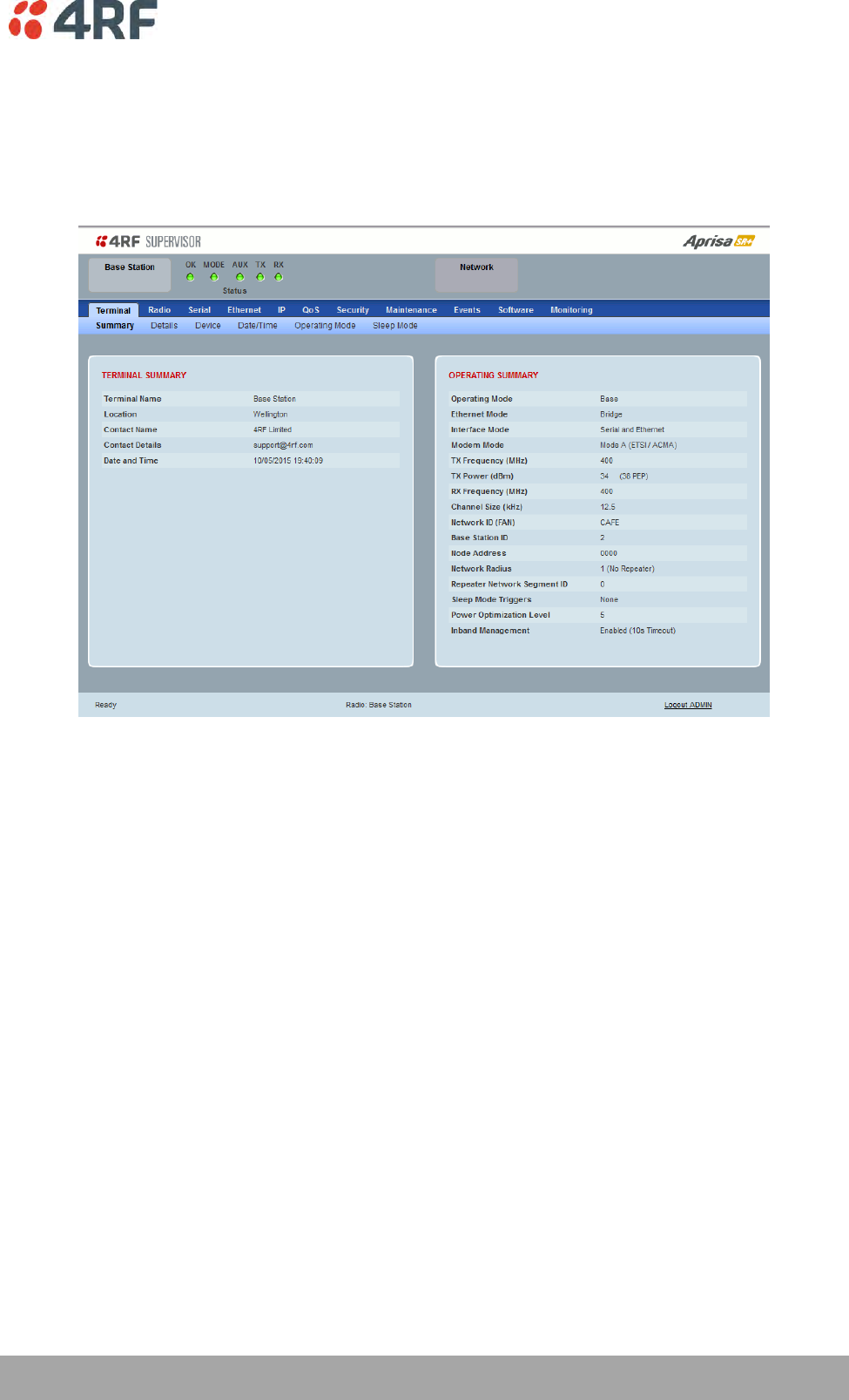
Managing the Radio | 83
Aprisa SR+ User Manual 1.6.0 PO
Standard Radio
Terminal
Terminal > Summary
TERMINAL SUMMARY
This page displays the current settings for the Terminal parameters. See ‘Terminal > Details’ on page 86,
‘Terminal > Device’ on page 88 and ‘Terminal > Operating Mode’ on page 94 for setting details.
OPERATING SUMMARY
Operating Mode
This parameter displays the current Operating Mode i.e. if the radio is operating as a base station,
repeater station or remote station and the network operating mode of Bridge Mode or Router Mode.
Interface Mode
This parameter displays the Interfaces available for traffic on the radio such as Ethernet and Serial. For
Ethernet availability on the radio see ‘Maintenance > Licence’ on page 216.
Modem Mode
This parameter displays the modem mode selected e.g. ETSI / FCC etc.

84 | Managing the Radio
Aprisa SR+ User Manual 1.6.0 PO
TX Frequency (MHz)
This parameter displays the current Transmit Frequency in MHz.
TX Power (dBm)
This parameter displays the current Transmit Power in dBm.
RX Frequency (MHz)
This parameter displays the current Receive Frequency in MHz.
Channel Size (kHz)
This parameter displays the current Channel Size in kHz.
Network ID
This parameter is the network ID of this base station node and its remote / repeater stations in the
network. The entry is four hex chars (not case sensitive).
Base Station ID
This parameter identifies the base station. All radios operating to the base station in the same network
must use the same Base Station ID setting.
It is especially important to set different values for each network when two or more networks using the
same frequencies are operating with some overlapping coverage. The entry is an integer from 1 to 8.
Node Address
The Node Address of the base station is 0000.
If the Node Address shown is FFFE, this radio is a remote station or repeater station but has not been
registered with the base station.
The base station will automatically allocate a Node Address to all its registered repeater station and
remote station radios. This address can be between 000B to 01FE.
Network Radius
This parameter displays the maximum number of hops in this network.
Network Repeaters Proximity
This parameter displays the proximity of repeaters in the network.

Managing the Radio | 85
Aprisa SR+ User Manual 1.6.0 PO
Repeater Network Segment ID
This parameter identifies a repeater network segment and its associated remotes.
In an overlapping coverage network where remote radios can ‘see’ multiple repeaters, it’s especially
important to set different values for each repeater network segment and its associated remotes, so the
associated remotes will communicate only with the appropriate repeater.
The same setting applies in remote overlapping coverage between a base and a repeater. Different values
per base and repeater are required if the requirements are that the remote will be communicating via the
repeater and not directly with the base station (or vice-versa), i.e. the repeater and remotes will have the
same value but different from the base station value. In this case, if the repeater fails, the remote will re-
register to the base station even though they are on different values until the repeater recovers.
The entry is an integer from 0 and 31, where 0 is reserved for broadcast i.e. all radios will ‘see’ this radio
traffic even if they are set to different values.
Inband Management
This parameter displays the status of the Inband Management option.
Inband Management Timeout (sec)
This parameter displays the number of seconds that the base station waits for a response from a Remote
or repeater station before aborting the Inband Management request.
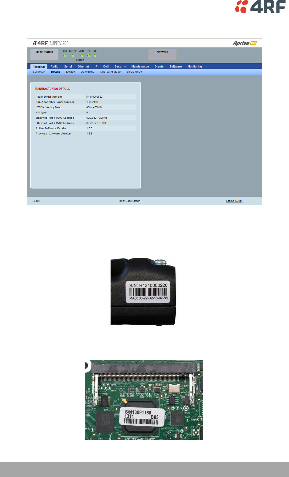
86 | Managing the Radio
Aprisa SR+ User Manual 1.6.0 PO
Terminal > Details
MANUFACTURING DETAILS
Radio Serial Number
This parameter displays the Serial Number of the radio (shown on the enclosure label).
Sub-Assembly Serial Number
This parameter displays the Serial Number of the printed circuit board assembly (shown on the PCB label).

Managing the Radio | 87
Aprisa SR+ User Manual 1.6.0 PO
HW Frequency Band
This parameter displays the hardware radio frequency operating range.
HW Type
This parameter displays the hardware board assembly type.
Radio MAC Address
This parameter displays the MAC address of the radio (the management Ethernet MAC address).
Active Software Version
This parameter displays the version of the software currently operating the radio.
Previous Software Version
This parameter displays the software version that was running on the radio prior to the current software
being activated.
A new radio from the factory will display ‘None’ for the Previous SW Version.
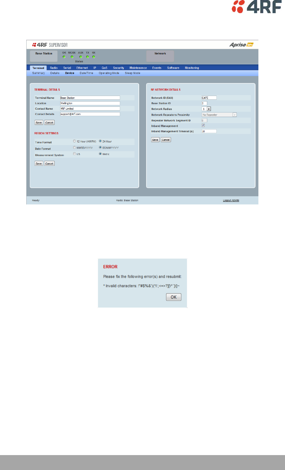
88 | Managing the Radio
Aprisa SR+ User Manual 1.6.0 PO
Terminal > Device
TERMINAL DETAILS
The data entry in the next four fields can be up to 40 characters but cannot contain invalid characters. A
popup warns of the invalid characters:
1. Enter the Terminal Name.
2. Enter the Location of the radio.
3. Enter a Contact Name. The default value is ‘4RF Limited’.
4. Enter the Contact Details. The default value is ‘support@4RF.com’.

Managing the Radio | 89
Aprisa SR+ User Manual 1.6.0 PO
RF NETWORK DETAILS
Network ID
This parameter sets the network ID of this base station node and its remote / repeater stations in the
network. The entry is four hexadecimal chars (not case sensitive).
The default setting is CAFE.
Base Station ID
This parameter identifies the base station. All radios operating to the base station in the same network
must use the same Base Station ID setting.
It is especially important to set different values for each network when two or more networks using the
same frequencies are operating with some overlapping coverage. The entry is an integer from 1 to 8.
Network Radius
This parameter sets the maximum number of hops in this network e.g. in a network with base station,
repeater and remotes communicating via the repeater, the Network Radius should be set to 2. If the
Network Radius is set to 2, a message from that node will only pass 2 hops before it is blocked.
The default setting is 1.
When base station is configured as a ‘Base-Repeater’ (used for remote peer to peer operation via the base
station), the use of Network Radius does not change and works the same as if it were a Base Station i.e.
the Network Radius is always the number of hops from the base station to the most distant remote in the
network.
All stations in the network should be set to the same value.
Network Repeaters Proximity
This parameter is set in base stations, remote stations and repeater stations to indicate the proximity of
repeaters in the network when the Network Radius is set to greater than 1.
Option
Function
No Repeater
Use when there is no repeater in the network.
Single Repeater Only
Use when there is only one repeater in the network.
Overlapping Coverage
Use for multiple one hop repeaters where the remote station can
see more than one repeater or repeaters can see each other.
The communication protocol is slower because each repeater is
addressed individually and in-turn.
Separated Coverage
Use for multiple one hop repeaters where the remote station can
only see one repeater and the repeaters can’t see each other.
This option provides better network downlink performance than
the Overlapping Coverage option.
However, if the repeaters can see each other, the resultant
collisions will cause corruptions and dramatically reduce network
downlink performance.
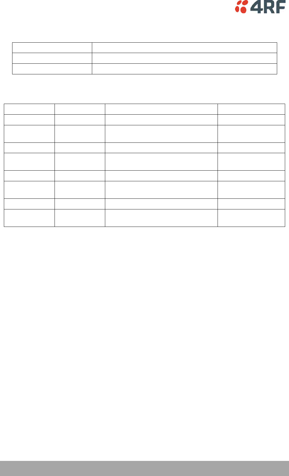
90 | Managing the Radio
Aprisa SR+ User Manual 1.6.0 PO
This parameter is set in remote stations to indicate the proximity of repeaters in the network when the
Network Radius is set to 1.
Option
Function
No Repeater
Use when there are no repeaters in the network.
Base Repeater
Use when there is a base-repeater in the network.
The Network Repeaters Proximity options are dependent on the Terminal Operating Mode and the
Terminal Network Radius settings:
Operating Mode
Network Radius
Network Repeaters Proximity Options
Default
Base
1
No Repeater
No Repeater
Base
2
Single Repeater Only, Overlapping
Coverage, Separated Coverage
Single Repeater Only
Remote
1
No Repeater, Base Repeater
No Repeater
Remote
2
Single Repeater Only, Overlapping
Coverage, Separated Coverage
Single Repeater Only
Repeater
1
No Repeater, Base Repeater
No Repeater
Repeater
2
Single Repeater Only, Overlapping
Coverage, Separated Coverage
Single Repeater Only
Base Repeater
1
Base Repeater
Base Repeater
Base Repeater
2
Single Repeater Only, Overlapping
Coverage, Separated Coverage
Single Repeater Only
Repeater Network Segment ID
This parameter identifies a repeater network segment and its associated remotes.
In an overlapping coverage network where remote radios can ‘see’ multiple repeaters, it’s especially
important to set different values for each repeater network segment and its associated remotes, so the
associated remotes will communicate only with the appropriate repeater.
The same setting applies in remote overlapping coverage between a base and a repeater. Different values
per base and repeater are required if the requirements are that the remote will be communicating via the
repeater and not directly with the base station (or vice-versa), i.e. the repeater and remotes will have the
same value but different from the base station value. In this case, if the repeater fails, the remote will re-
register to the base station even though they are on different values until the repeater recovers.
The entry is an integer from 0 and 31, where 0 is reserved for broadcast i.e. all radios will ‘see’ this radio
traffic even if they are set to different values.
Inband Management
This parameter sets the Inband Management option.
If the Inband Management option is enabled, SuperVisor operating on a base station can also manage all
the remote / repeater stations in the network.
Inband Management Timeout (sec)
This parameter sets the Inband Management timeout period. This determines the time the base station
waits for a response from a remote or repeater station before aborting the Inband Management request.
The default setting is 10 seconds.

Managing the Radio | 91
Aprisa SR+ User Manual 1.6.0 PO
REGION SETTINGS
Time Format
This parameter sets the time format for all time based results.
The default setting is 24 Hours.
Date Format
This parameter sets the date format for date based results.
The default setting is DD/MM/YYYY.
Measurement System
This parameter sets the unit type for parameters like temperature readings.
The default setting is Metric.
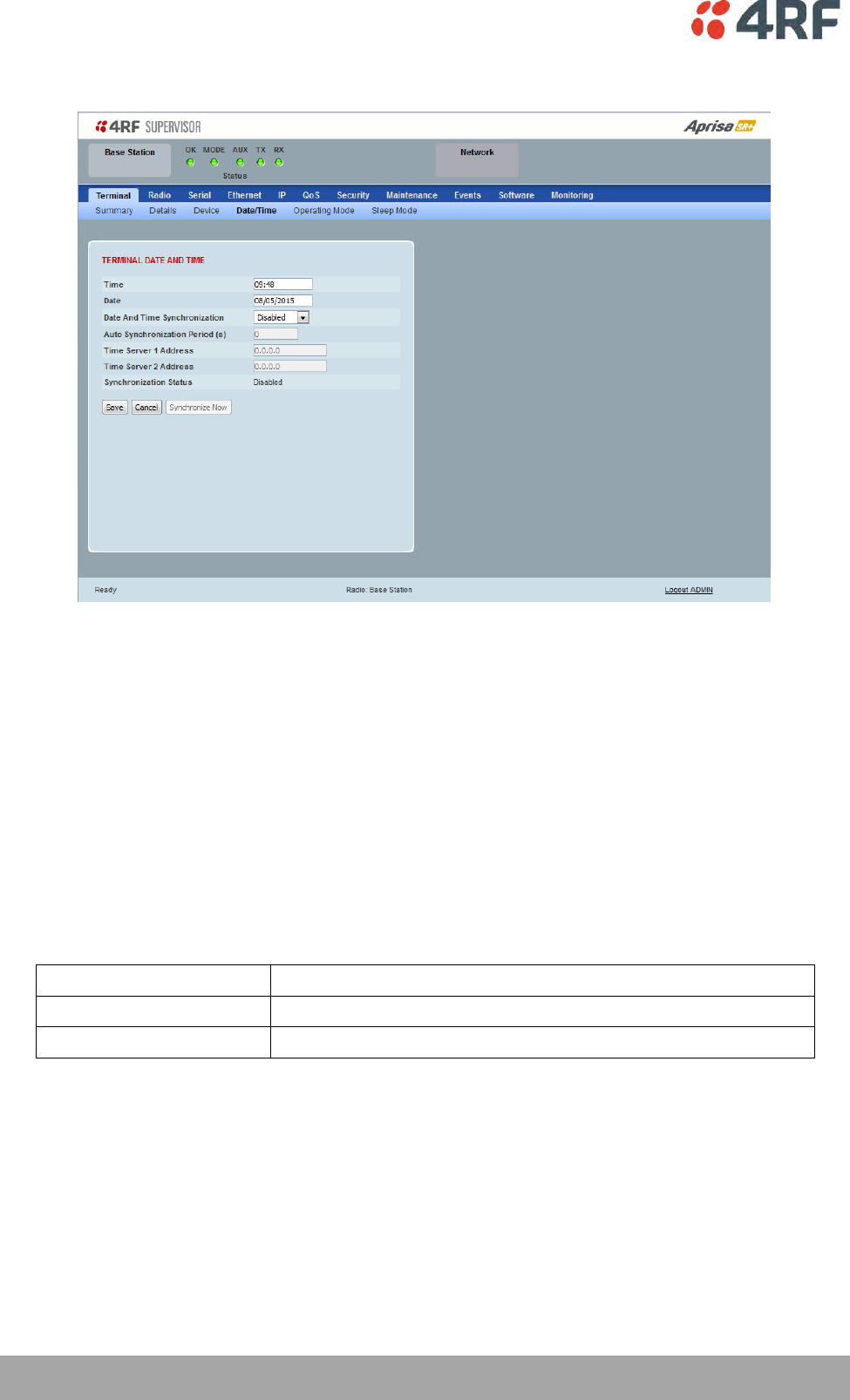
92 | Managing the Radio
Aprisa SR+ User Manual 1.6.0 PO
Terminal > Date / Time
TERMINAL DATE AND TIME
Sets the Time and Date. This information is controlled from a software clock.
Date and Time Synchronization
This Date and Time Synchronization feature allows a radio to synchronize its date and time from an SNTP
server. It would predominantly be used on the base station but could be used on a remote station.
Using the SNTP feature will ensure that all radios in the network has the same date and time required for
accurate network diagnostics.
For high availability time/date synchronization, SNTP can be synchronized from two SNTP servers for
server backup.
The default setting is Disabled.
Option
Function
Disabled
No SNTP Date and Time Synchronization
SNTP
Date and Time will be synchronized to a SNTP server
The base station periodically sends a broadcast message to the remote stations to synchronize the radio
date and time.

Managing the Radio | 93
Aprisa SR+ User Manual 1.6.0 PO
Auto Synchronization Period (s)
This parameter sets the number of seconds between the end of the last synchronization and the next
synchronization attempt. The minimum period is 60 seconds. A period of 0 seconds will disable
synchronization attempts.
Time Server 1 Address
This parameter sets the IP address of the first priority SNTP server. If the synchronization is successful to
this server, Time Server 2 Address will not be used.
Time Server 2 Address
This parameter sets the IP address of the second priority SNTP server. If the synchronization fails using the
SNTP server on Time Server 1 Address, synchronization will be attempted to the SNTP server on this
address.
Synchronization Status
This field shows the status of the current synchronization or the result of the last synchronization.
Synchronize Now
This Synchronize Now button provides manual Synchronization.
94 | Managing the Radio
Aprisa SR+ User Manual 1.6.0 PO
Terminal > Operating Mode
OPERATING MODES
Terminal Operating Mode
The Terminal Operating Mode can be set to Base, Base Repeater, Repeater, Remote or Point-To-Point
station. The default setting is Remote.
Option
Function
Base
The base station manages all traffic activity between itself,
repeaters and remotes. It is the center-point of network where in
most cases will be connected to a SCADA master.
Base Repeater
The base-repeater has the same function as the base station (and
repeater station), but used when peer to peer connections
between remotes is required via the base station.
Base MMS
The Base-MMS has the same function as the base station, but used
when Migration Master Station operation is required (see Aprisa SR+
MMS User Manual).
Repeater
The repeater forwards packets coming from base station and other
repeaters e.g. in daisy chain LBS mode and /or remote stations.
Remote
The remote in most cases is used as the end-point of the SCADA
network connected to an RTU or PLC device for SCADA network
control and monitoring.
Point To Point
Configures a full duplex radio for Point-To-Point (PTP) operation.
Changing from PMP or PTP or vice versa requires the radio to be
‘restored to factory default settings’ which will clear all previous
radio setup and configuration.
See Aprisa SR+ User Manual 1.6.0 PTP for all Point-To-Point setup
and configuration.
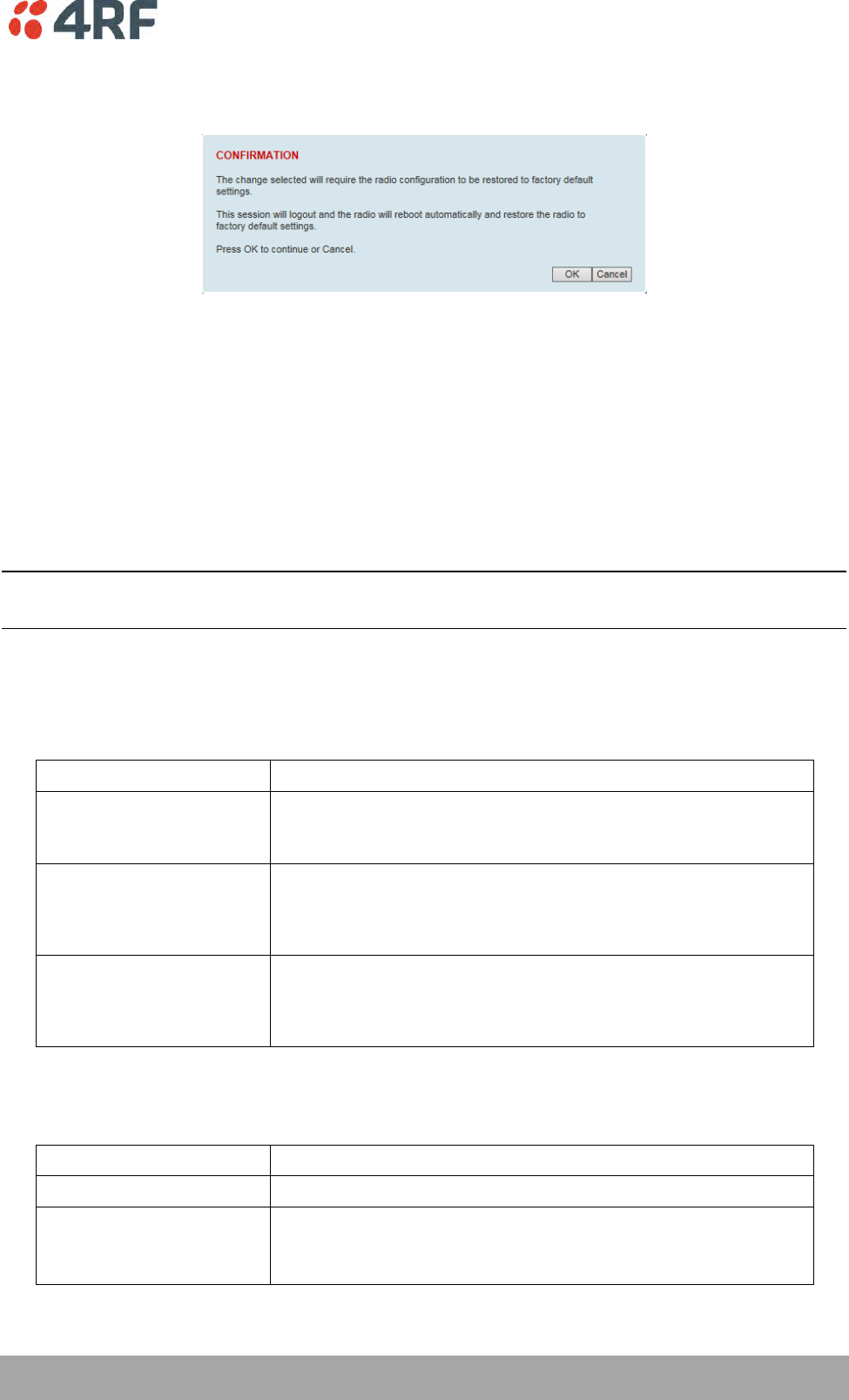
Managing the Radio | 95
Aprisa SR+ User Manual 1.6.0 PO
When the Terminal Operating Mode is changed from PMP to PTP or vice versa, the following popup will
warn of the ‘restore to factory default settings’.
SR Compatible
The SR Compatible option enables over-the–air point-to-multipoint interoperation between an Aprisa SR+
network and New Aprisa SR radios. The default setting is unticked.
When the Aprisa SR+ ‘SR Compatible’ option is activated, the Aprisa SR+ locks its modulation to QPSK (as
per the New Aprisa SR modulation) and disables functionality which is not available in New Aprisa SR for
full compatibility / interoperability operation.
This compatibility option allows the user a smooth migration to Aprisa SR+ when higher speeds of 120,
60 kbit/s (at 25, 12.5 kHz channel sizes), Adaptive Coding and Modulation, full duplex and more features
are required.
Note: Any mix between the New Aprisa SR and Aprisa SR+ in the network will force the whole network to
work in SR Compatible mode.
Ethernet Operating Mode
The Ethernet Operating Mode defines how Ethernet / IP traffic is processed in the radio. The default
setting is Bridge.
Option
Function
Bridge
Bridge mode inspects each incoming Ethernet frame source and
destination MAC addresses to determine if the frame is forwarded
over the radio link or discarded.
Gateway Router
Gateway Router mode inspects each incoming IP source and
destination IP addresses to determine if the packet is forwarded
over the radio link or discarded. In this mode, all Ethernet
interfaces have the same IP address and subnet.
Router
Router mode inspects each incoming IP source and destination IP
addresses to determine if the packet is forwarded over the radio
link or discarded. In this mode, each Ethernet interface has a
different IP address and subnet.
RF Operating Mode
The RF Operating Mode defines the operation of the RF over-the-air. The default setting is Standard.
Option
Function
Standard
The radio operates normally.
Disabled
Disables all RF over-the-air communications from the RF port and
turns of the transmitter and receiver to save power.
This enables a radio to be used as a Terminal Server without RF.

96 | Managing the Radio
Aprisa SR+ User Manual 1.6.0 PO
TERMINAL PROTECTION
Protection Type
The Protection Type defines if a radio is a stand-alone radio or part of an Aprisa SR+ Protected Station.
The default setting is None.
Option
Function
None
The SR+ radio is stand-alone radio (not part of an Aprisa SR+
Protected Station).
Redundant
(Protected Station)
Set to make this SR+ radio part of an Aprisa SR+ Protected Station.
The RF ports and interface ports from two standard Aprisa SR+
radios are switched to the standby radio if there is a failure in the
active radio
Monitored Hot Standby
(Protected Station)
Set to make this SR+ radio part of an Aprisa SR+ Protected Station.
The RF ports and interface ports from two standard Aprisa SR+
radios are switched to the standby radio if there is a failure in the
active radio.
The standby radio is monitored to ensure its correct operation
should a switch-over be required. See ‘Monitored Alarms’ on page
333 for the list of monitored alarms.
Serial Data Driven Switching
Set to make this SR+ radio part of an Aprisa SR+ Data Driven
Protected Station.
Protection Unit
The Protection Unit defines if this radio is the primary radio or secondary radio in a Protected Station.
One radio in the Protected Station is set to Primary and the other radio to Secondary.
It is recommended that radio A (the left radio) be configured as the Primary and that radio B (the right
radio) be configured as the Secondary. The default setting is Primary.
This menu item is only applicable if this radio is to become part of an Aprisa SR+ Protected Station.
PROTECTION MANAGEMENT IP ADDRESS
Local IP Address
The Local IP Address shows the IP address of this radio.
Partner IP Address
The Partner IP Address parameter is used to set the partner IP address if this radio is to become part of a
Protected Station.
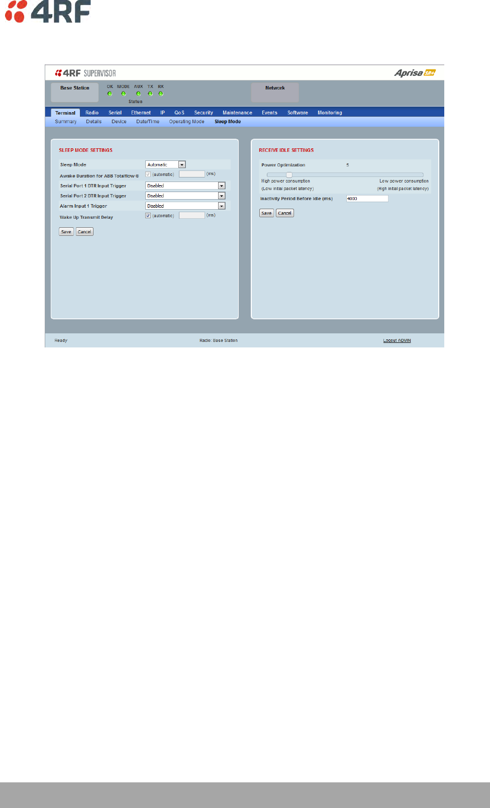
Managing the Radio | 97
Aprisa SR+ User Manual 1.6.0 PO
Terminal > Sleep Mode
SLEEP MODE SETTINGS
Sleep mode allows the radio to be put to sleep where it consumes very little power (< 0.5 watts with all
Ethernet ports disabled) but allows rapid wake up.
The sleep and wake up is controlled from the serial port DTR inputs or the Alarm Input 1. If sleep mode is
enabled for serial port DTR trigger and the customer serial interface is not connected, the radio will
sleep.
When radio is in sleep mode, the OK LED pulses once per second at a colour depending on the current
state of the OK LED before sleep mode was entered and the other LEDs will be OFF.
Sleep mode will be disabled and sleeping radio will be woken up while a management user is logged into
the radio or when a USB CLI cable is inserted in the management port.
Sleep mode will be disabled and sleeping radio will be woken up when an Ethernet cable is inserted into
an enabled Ethernet port configured for ‘management and user data’, however 60 seconds after insertion,
the radio will be allowed to enter sleep unless the user has logged into SuperVisor.
Pressing the radio ‘test’ button will also wake up a sleeping radio for 5 minutes.
98 | Managing the Radio
Aprisa SR+ User Manual 1.6.0 PO
Sleep Mode
The Sleep Mode parameter sets how sleep mode is controlled. The default setting is Automatic.
Option
Function
Automatic
If this radio is a remote, it uses the setting from the base station.
If this radio is the base station, the external triggers control the
radio sleep mode state.
Standard
The external triggers control the radio sleep mode state.
ABB Totalflow ®
The external trigger wakes up the radio for up to the maximum
duration set in the ‘Awake Duration’ or indefinitely if data is sent
to the RTU.
Awake Duration for ABB Totalflow ®
The Awake Duration sets the radio awake duration when there is no data being sent to the RTU.
Triggers
The triggers when enabled cause the radio to sleep or wake up. For the radio to sleep, all the enabled
triggers must be OFF i.e. if only one enabled trigger goes ON, the radio will wake up.
Serial Port 1 / 2 DTR Trigger
The Serial Port 1 / 2 DTR Trigger controls the radio sleep and wake up. The default setting is Disabled.
Option
Function
Disabled
The Serial Port DTR has no effect on sleep mode.
Active Low (sleep when
input is low)
The Serial Port DTR ON state causes the radio to wake up and the
DTR OFF state allows the radio to sleep.
Note: There must be valid RS-232 signals on either the RTS or RX
lines for the radio to go to sleep (when DTR is ON).
The RS-232 specification defines valid control states as:
ON state or 0-state (SPACE) condition = +3 to +12 volts
OFF state or 1-state (MARK) condition = -3 to -12 volts
Alarm Input 1 Trigger
The Alarm Input 1 Trigger controls the radio sleep and wake up. The default setting is Disabled.
Option
Function
Disabled
The Alarm Input 1 has no effect on sleep mode.
Active Low(sleep when
input is low)
The Alarm Input 1 high (ON) state causes the radio to wake up and
the low (OFF) state allows the radio to sleep (see ‘Alarm Inputs’ on
page 396 for alarm input specification).
Note: If the alarm input is disconnected (e.g. alarm cable
unplugged), the radio will go to sleep.

Managing the Radio | 99
Aprisa SR+ User Manual 1.6.0 PO
Wake Up Transmit Delay (ms)
The Wake Up Transmit Delay (ms) sets the maximum time to check if the channel is clear before the radio
attempts to transmit. The transmitter will wait for either;
a packet to be received from the base station or
the expiry of the Wake Up Transmit Delay
The default setting is Ticked (Automatic) which automatically calculates the best case for this delay for
the current radio settings. This value will be between 0.4 second and 2 seconds depending on channel size
and compliance mode.
The following are the default Wake Up Transmit delays;
Channel Size
Wake Up Transmit Delay
(seconds)
12.5 kHz
1.6
20 kHz
1.1
25 kHz
0.8
50 kHz
0.41
Maximum Power Savings
If the Ethernet ports are not required for customer traffic, maximum power savings can be achieved by
disabling them. This will however prevent SuperVisor management with Ethernet. The Ethernet ports can
only be restored using SNMP or the CLI.
To enable Ethernet ports from the CLI:
1. Plug the USB CLI cable from your PC into the management port (MGMT). This will wake a radio that is
sleeping.
2. Login to the CLI. The default login is Login: ‘admin’ Password: ‘admin’
3. At the CLI prompt >> type ‘cd APRISASR-MIB-4RF’ enter
4. At the CLI prompt >> type ‘set ethPort1Enabled 1’ enter (for port 1)
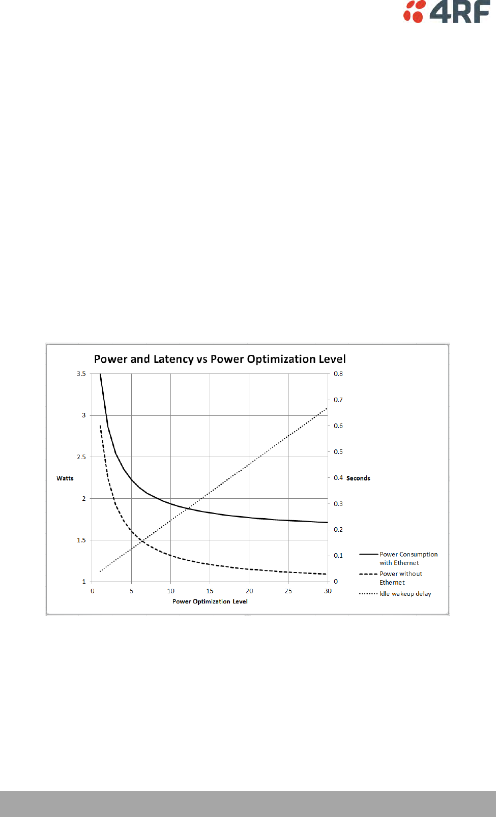
100 | Managing the Radio
Aprisa SR+ User Manual 1.6.0 PO
RECEIVE IDLE SETTINGS
Radio power consumption in idle mode is lowered by turning off the receiver when remote radios know
that packet reception is not possible. This feature only works with the Access Request MAC as the Listen
Before Send MAC cannot know that packet reception is not possible.
The base station receiver never goes into idle mode and is always on.
When a remote radio’s receiver is in idle mode, the base station must send a series of idle exit packets
before it can send a data packet or allow a remote to send a data packet. This is to ensure that all
remotes can receive the data packet.
Power Optimization Level
The Power Optimization Level sets the remote radio receiver on/off ratio.
The longer the receiver is off for, the less the idle power consumption but the higher the initial packet
latency.
The shorter the receiver is off for, the more the idle power consumption but the lower the initial packet
latency.
All radios in an Aprisa SR+ network must use the same Power Optimization Level setting.
The default setting is 5.
Inactivity Period Before Idle (ms)
The Inactivity Period Before Idle (ms) sets the delay remote radios configured for Access Request MAC will
wait before entering a power saving ‘idle’ state.
All radios in an Aprisa SR+ network must use the same Inactivity Period Before Idle setting.
The default setting is 4000 ms.
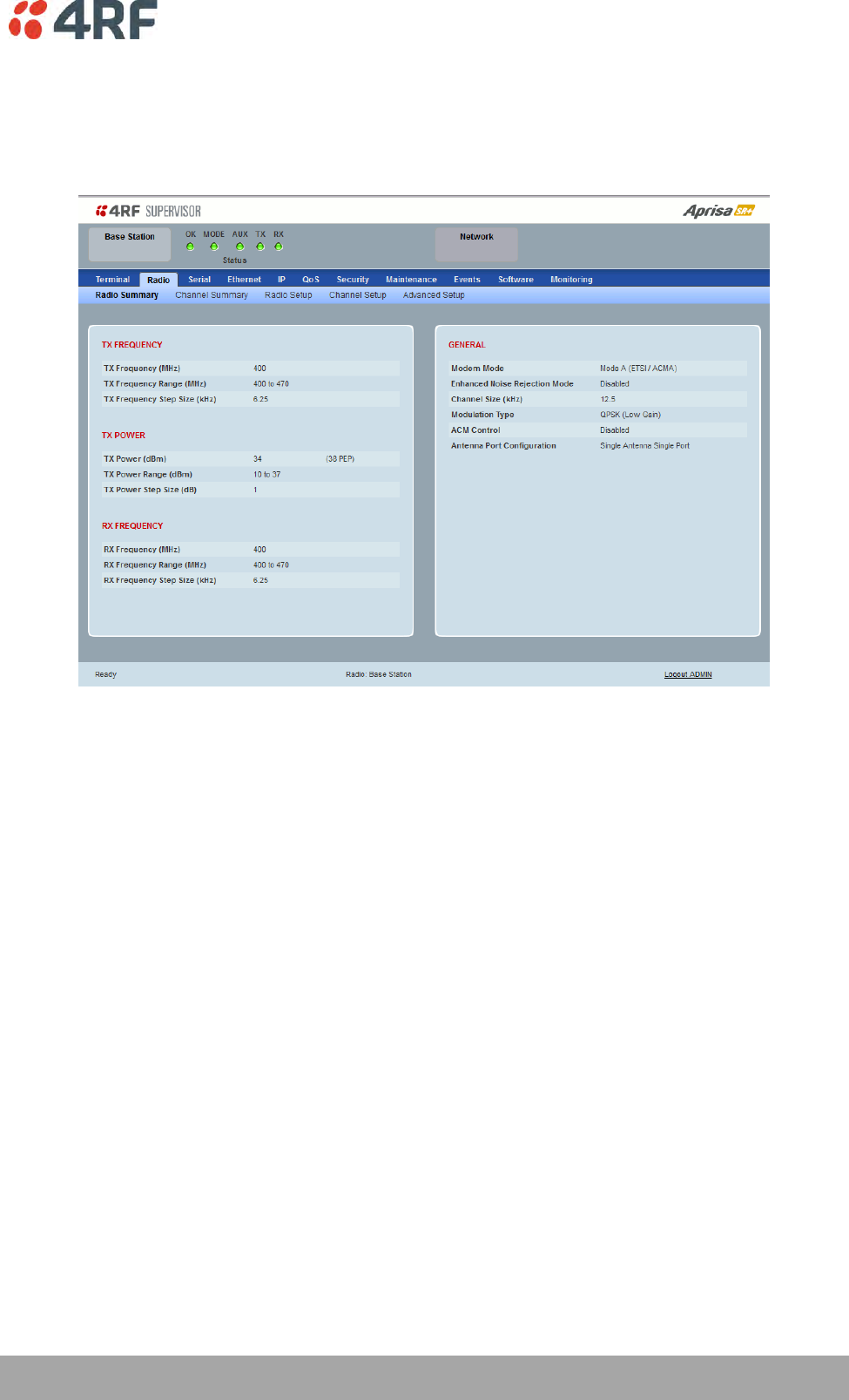
Managing the Radio | 101
Aprisa SR+ User Manual 1.6.0 PO
Radio
Radio > Radio Summary
This page displays the current settings for the Radio parameters.
See ‘Radio > Radio Setup’ and ‘Radio > Channel Setup’ for setting details.
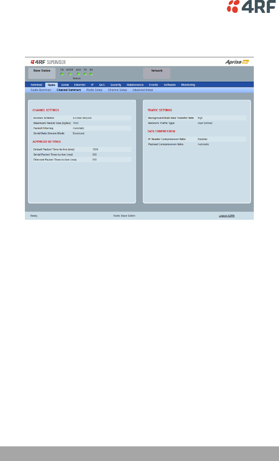
102 | Managing the Radio
Aprisa SR+ User Manual 1.6.0 PO
Radio > Channel Summary
This page displays the current settings for the Channel parameters.
See ‘Radio > Channel Setup’ for setting details.
DATA COMPRESSION
IP Header Compression Ratio
See ‘IP Header Compression Ratio’ on page 119.
Payload Compression Ratio
The payload is compressed using level 3 QuickLZ data compression. Payload Compression is automatic and
cannot be turned off by SuperVisor.
Compression is not attempted on data that is already compressed e.g. jpg files.
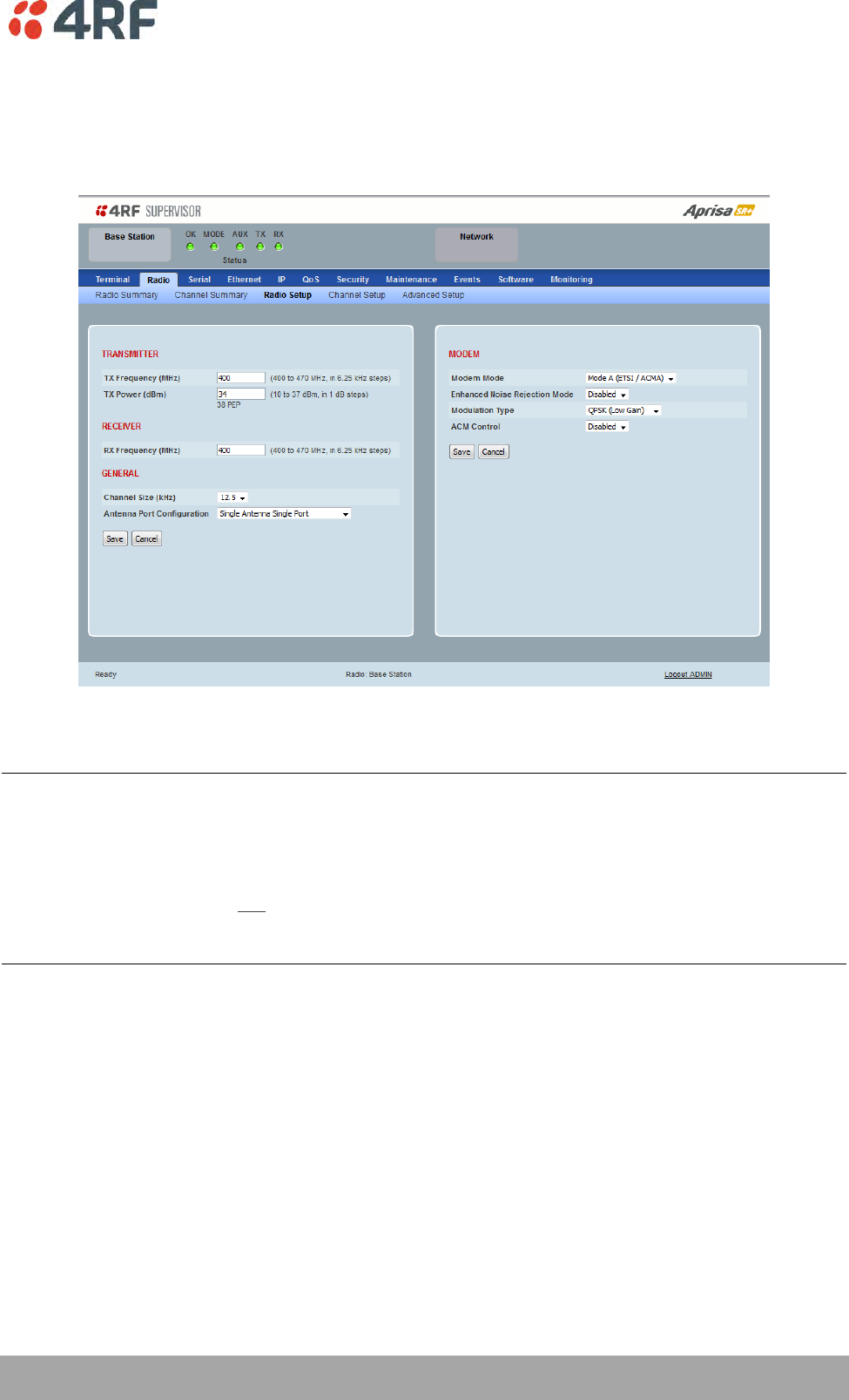
Managing the Radio | 103
Aprisa SR+ User Manual 1.6.0 PO
Radio > Radio Setup
Transmit frequency, transmit power and channel size would normally be defined by a local regulatory
body and licensed to a particular user. Refer to your site license details when setting these fields.
TRANSMITTER / RECEIVER
Important:
1. Changing the remote / repeater station frequencies will disable all management communication to the
remote / repeater stations but then by changing the base station to match the remote / repeater stations,
the radio links will be restored as will the management communication.
2. Enter the TX frequency and the RX frequency and then click ‘Save’. This is to prevent remote
management communication from being lost before both frequencies have been changed in the remote
stations.
TX and RX Frequencies.
The TX and RX frequencies entered must be within the frequency tuning range of the product frequency
band (see ‘Frequency Bands’ on page 375).
If the frequency entered is not resolvable to the synthesizer step size for the frequency band it is
rejected. For example; a 400 MHz radio has a synthesizer step size of 6.250 kHz.
The TX and RX frequencies can be single frequency half duplex or dual frequency half duplex. Dual
frequency half duplex is often used for reasons of:
Channel Planning
Network Efficiencies
Regulatory rules
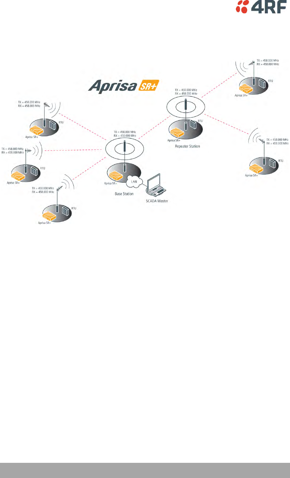
104 | Managing the Radio
Aprisa SR+ User Manual 1.6.0 PO
Single Frequency Operation
The TX and RX frequencies of the base station, repeater station and all the remote stations are on the
same frequency.
To change the TX and RX frequencies:
1. Change the TX and RX frequencies of the remote stations operating from the repeater station to the
new frequency. The radio links to these remote stations will fail.
2. Change the TX and RX frequencies of the repeater station operating from the base station to the new
frequency. The radio links to the repeater station and its remote stations will fail.
3. Change the TX and RX frequencies of the remote stations operating from the base station to the new
frequency. The radio links to these remote stations will fail.
4. Change the TX and RX frequencies of the base station to the new frequency. The radio links to all
stations will restore.
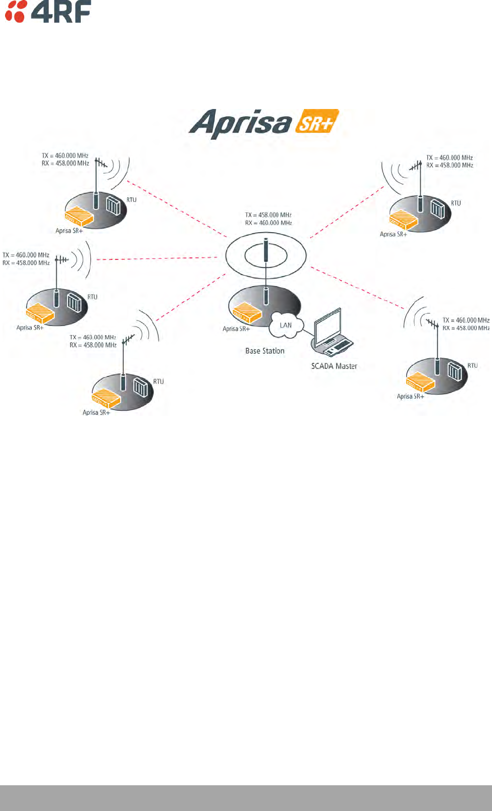
Managing the Radio | 105
Aprisa SR+ User Manual 1.6.0 PO
Dual Frequency No Repeater
The TX frequency of all the remote stations matches the RX frequency of the base station.
The RX frequency of all the remote stations matches the TX frequency of the base station.
To change the TX and RX frequencies:
1. For all the remote stations, change the RX frequency to frequency A and the TX frequency to
frequency B. The radio links to the remote stations will fail.
2. For the base station, change the TX frequency to frequency A and the RX frequency to frequency B.
The radio links to the remote stations will restore.
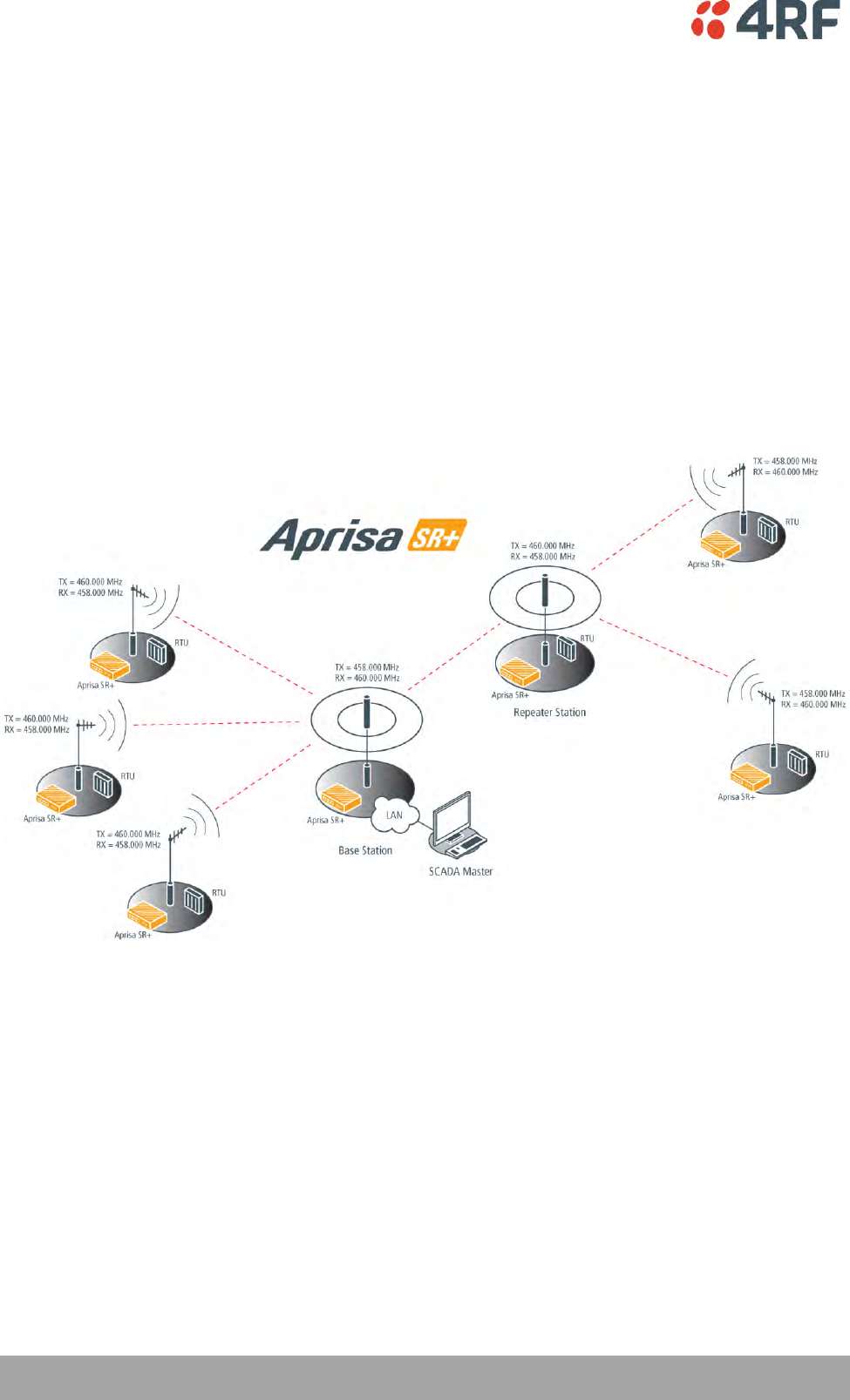
106 | Managing the Radio
Aprisa SR+ User Manual 1.6.0 PO
Dual Frequency with Repeater
The TX frequency of the remote stations associated with the base station matches the RX frequency of the
base station.
The TX frequency of the repeater station associated with the base station matches the RX frequency of
the base station.
The TX frequency of the remote stations associated with the repeater station matches the RX frequency of
the repeater station.
The RX frequency of the remote stations associated with the base station matches the TX frequency of the
base station.
The RX frequency of the repeater station associated with the base station matches the TX frequency of
the base station.
The RX frequency of the remote stations associated with the repeater station matches the TX frequency of
the repeater station.

Managing the Radio | 107
Aprisa SR+ User Manual 1.6.0 PO
To change the TX and RX frequencies:
1. For all the remote stations operating from the repeater station, change the RX frequency to frequency
A and the TX frequency to frequency B. The radio links to these remote stations will fail.
2. For the repeater station, change the TX frequency to frequency A and the RX frequency to frequency
B. The remote stations operating from the repeater station, will now establish a connection to the
repeater.
3. For all the remote stations operating from the base station, change the TX frequency to frequency A
and the RX frequency to frequency B. The radio links to these remote stations will fail.
4. For the base station, change the RX frequency to frequency A and the TX frequency to frequency B.
The radio links to the remote stations operating from the repeater station or the base station will
restore.
TX Power
The transmitter power is the power measured at the antenna output port when transmitting. The
transmitter power has a direct impact on the radio power consumption.
The default setting is +37 dBm.
If TX Power setting is higher than the high limit or lower than the low limit for the current modulation, an
Informational Event (55 Terminal Unit Information) will be raised to notify the user that transmit power
has been changed. This only applies to fixed modulation (not ACM).
Note: The Aprisa SR+ transmitter contains power amplifier protection which allows the antenna to be
disconnected from the antenna port without product damage.

108 | Managing the Radio
Aprisa SR+ User Manual 1.6.0 PO
GENERAL
Channel Size (kHz)
This parameter sets the Channel Size for the radio (see ‘Channel Sizes’ on page 376 for Radio Capacities).
The default setting is 12.5 kHz.
Antenna Port Configuration
This parameter sets the Antenna Port Configuration for the radio.
Option
Function
Single Antenna
Single Port
Select Single Antenna Single Port if using one or two frequency half
duplex transmission. The antenna is connected to the ANT port.
Single Antenna Dual
Port (duplexer)
Select Single Antenna Dual Port if using:
(1) One or two frequency in half duplex transmission with an
external duplexer (for filtering) connected to the ANT/TX and RX
antenna ports and single antenna connected to the duplexer.
(2) Two frequency in full duplex transmission with an external
duplexer (for full duplex operation) connected to the ANT/TX and
RX antenna ports and single antenna connected to the duplexer.
(3) Single frequency in half duplex transmission with external dual
antennas, connected to the ANT/TX and RX antenna ports.
(4) Two frequency in half or full duplex transmission with external
dual antennas, connected to the ANT/TX and RX antenna ports.
The default setting is Single Antenna Single Port.
Managing the Radio | 109
Aprisa SR+ User Manual 1.6.0 PO
MODEM
The Radio > Radio Setup screen Modem section is different for a base / repeater / base-repeater station
and a remote station.
Modem Mode
This parameter sets the Modem Mode in the radio. The Modem Mode option list is dependent on the radio
Hardware Variant.
HW Variant
Option
Channel Sizes
135 MHz
Mode A (FCC / IC)
15 and 30 kHz
Mode B (ETSI / ACMA)
12.5 and 25 kHz
220 MHz
Mode A (FCC / IC)
12.5, 15, 25 and 50 kHz
320 MHz
Mode A (ETSI / ACMA)
12.5, 20, 25 and 50 kHz
400 MHz
Mode A (ETSI / ACMA)
12.5, 20, 25 and 50 kHz
Mode B (FCC / IC)
12.5, 25 and 50 kHz
450 MHz
Mode A (ETSI / ACMA)
12.5, 25 and 50 kHz
Mode B (FCC)
12.5 and 25 kHz
700 MHz
Mode A (FCC)
25, 50 and 75 kHz
896 MHz
Mode A (FCC / IC)
12.5, 25 and 50 kHz
Mode B (FCC Part 24)
12.5, 25 and 50 kHz
Mode C (IC RSS-134)
12.5, 25 and 50 kHz
928 MHz
Mode A (FCC)
12.5, 25 and 50 kHz
Mode B (IC)
12.5, 25 and 50 kHz
Mode C (FCC Part 24)
12.5, 25 and 50 kHz
Mode D (IC RSS-134)
12.5, 25 and 50 kHz
Enhanced Noise Rejection Mode
This parameter enables / disables the Enhanced Noise Rejection Mode in the radio. This feature improves
co-channel interference performance at strong receiver signal levels. All radios in an Aprisa SR+ network
must use the same setting i.e. enabled or disabled.
The default setting is Disabled.

110 | Managing the Radio
Aprisa SR+ User Manual 1.6.0 PO
Modulation Type
The base to remote / repeater or repeater to remote / base direction of transmission is always fixed i.e.
not adaptive.
This parameter sets the fixed TX Modulation Type for the base / base-repeater / repeater radio.
Option
Function
QPSK (High Gain)
Sets the modulation to QPSK with Max Coded FEC.
QPSK (Low Gain)
Sets the modulation to QPSK with Min Coded FEC.
QPSK
Sets the modulation to QPSK with no FEC.
16QAM (High Gain)
Sets the modulation to 16 QAM with Max Coded FEC.
16QAM (Low Gain)
Sets the modulation to 16 QAM with Min Coded FEC.
16QAM
Sets the modulation to 16 QAM with no FEC.
64QAM (High Gain)
Sets the modulation to 64 QAM with Max Coded FEC.
64QAM (Low Gain)
Sets the modulation to 64 QAM with Min Coded FEC.
The default setting is QPSK (Low Gain).
The base / base-repeater radio TX modulation will be set based on the worse case (RSSI) path profile
scenario of all the radios (remotes and repeaters) in one hop distance from the base / base-repeater
radio.
The repeater radio TX modulation will be set based on the worse case (RSSI) path profile scenario of all
the radios (remotes and base) in one hop distance from the repeater radio.

Managing the Radio | 111
Aprisa SR+ User Manual 1.6.0 PO
ACM Control (base station only)
This parameter enables / disables Adaptive Code Modulation for the remote to base direction of
transmission (upstream).
When ACM is enabled (ACM Control set to Standard or Fast), the base station sends a modulation type
recommendation to each remote radio based on the signal quality for each individual remote radio.
Option
Function
Disabled
Disables Adaptive Code Modulation for the upstream.
The base station does not send a modulation type recommendation
to any remote radio.
Fast
Enables Adaptive Code Modulation for the upstream.
The ACM will switch down one ACM level if an errored packet is
received.
The ACM will switch up when the link quality exceeds the
performance threshold.
This option maintains the highest network speeds for as long as
possible.
Standard
Enables Adaptive Code Modulation for the upstream.
The ACM will switch down one ACM level if the link quality
degrades in advance of the level where errored packets would be
expected and will switch to the lowest ACM level if an errored
packet is received.
The ACM will switch up when the link quality exceeds the
performance threshold.
This option preserves packet integrity but reduces network speeds.
The default setting is Fast.
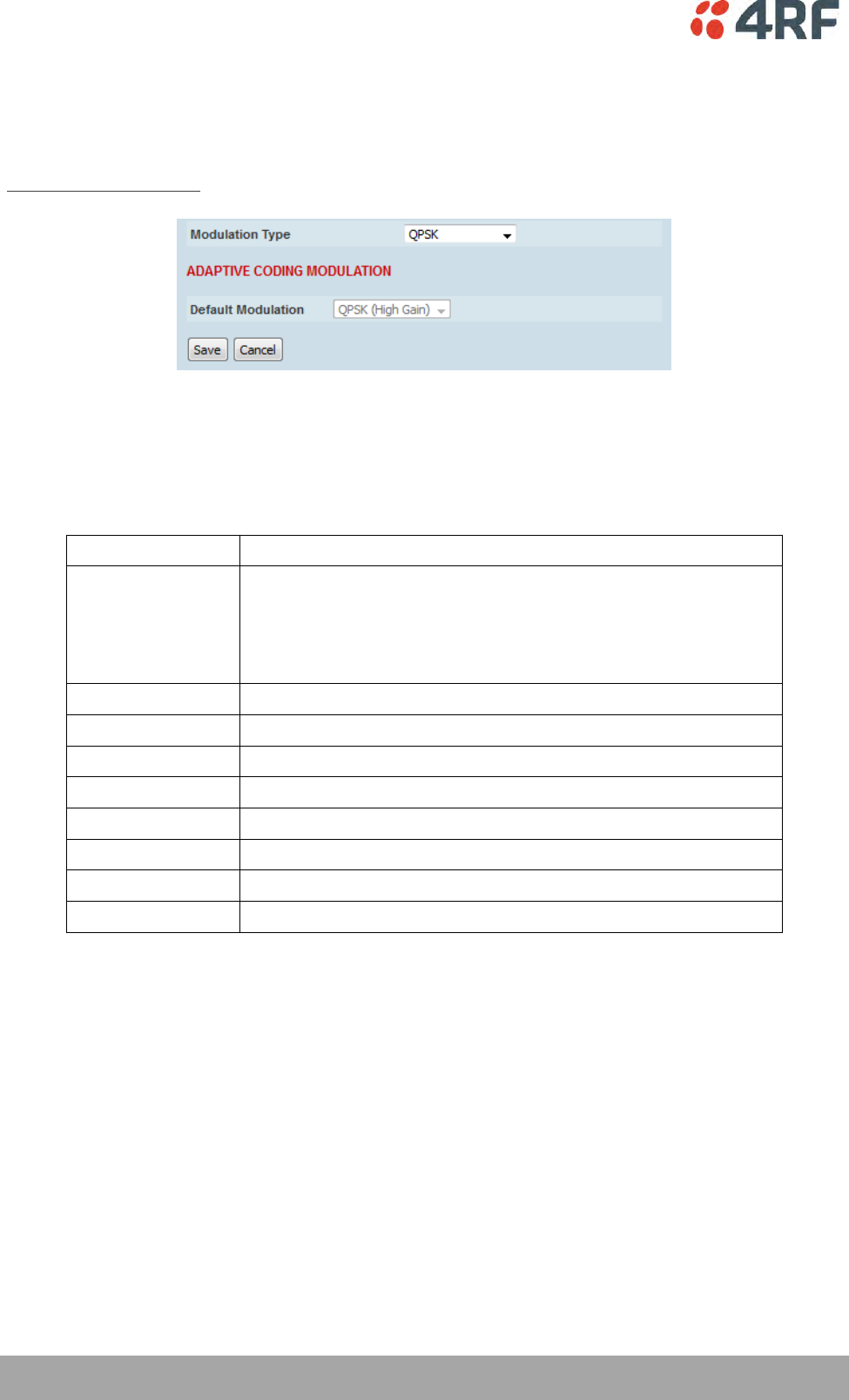
112 | Managing the Radio
Aprisa SR+ User Manual 1.6.0 PO
ADAPTIVE CODING AND MODULATION
These settings are only used if the Modulation Type is set to Adaptive and only apply to the remote to
base / base-repeater / repeater direction of transmission (upstream).
MODEM - Remote Station
Modulation Type
The remote to base / base-repeater / repeater direction of transmission can be adaptive modulation or
fixed modulation.
This parameter sets the TX Modulation Type for the remote station radio.
Option
Function
Adaptive
Sets the modulation type to Adaptive Code Modulation.
The remote radio receives the modulation type recommendation
from the base / base-repeater / repeater station and adjusts the
modulation and FEC code rate in the remote to base / base-
repeater / repeater direction of transmission (upstream).
QPSK (High Gain)
Sets the modulation to QPSK with Max Coded FEC.
QPSK (Low Gain)
Sets the modulation to QPSK with Min Coded FEC.
QPSK
Sets the modulation to QPSK with no FEC.
16QAM (High Gain)
Sets the modulation to 16 QAM with Max Coded FEC.
16QAM (Low Gain)
Sets the modulation to 16 QAM with Min Coded FEC.
16QAM
Sets the modulation to 16 QAM with no FEC.
64QAM (High Gain)
Sets the modulation to 64 QAM with Max Coded FEC.
64QAM (Low Gain)
Sets the modulation to 64 QAM with Min Coded FEC.

Managing the Radio | 113
Aprisa SR+ User Manual 1.6.0 PO
Default Modulation
This parameter sets the default modulation and FEC code rate for the remote to base / base-repeater /
repeater direction of transmission when the ACM mechanism fails for whatever reason. It is also used
when the radio starts up, and subsequently, if there are no recommendations received from the base /
base-repeater / repeater station, it will remain at that setting.
Upstream recommendations are always expected to be received from the base / base-repeater / repeater
station. For example, when the base / base-repeater / repeater station 'ACM control' is set to 'disabled'
and the 'modulation type' at the remote is set to 'adaptive', the default modulation will be used. In this
case, the base / base-repeater / repeater station will not recommend any changes to the remote radios
and so the remote radio will remain on the configured ‘Default Modulation’.
This parameter sets the TX Modulation Type for the remote station radio.
Option
Function
QPSK (High Gain)
Sets the modulation to QPSK with Max Coded FEC.
QPSK (Low Gain)
Sets the modulation to QPSK with Min Coded FEC.
QPSK
Sets the modulation to QPSK with no FEC.
16QAM (High Gain)
Sets the modulation to 16 QAM with Max Coded FEC.
16QAM (Low Gain)
Sets the modulation to 16 QAM with Min Coded FEC.
16QAM
Sets the modulation to 16 QAM with no FEC.
64QAM (High Gain)
Sets the modulation to 64 QAM with Max Coded FEC.
64QAM (Low Gain)
Sets the modulation to 64 QAM with Min Coded FEC.
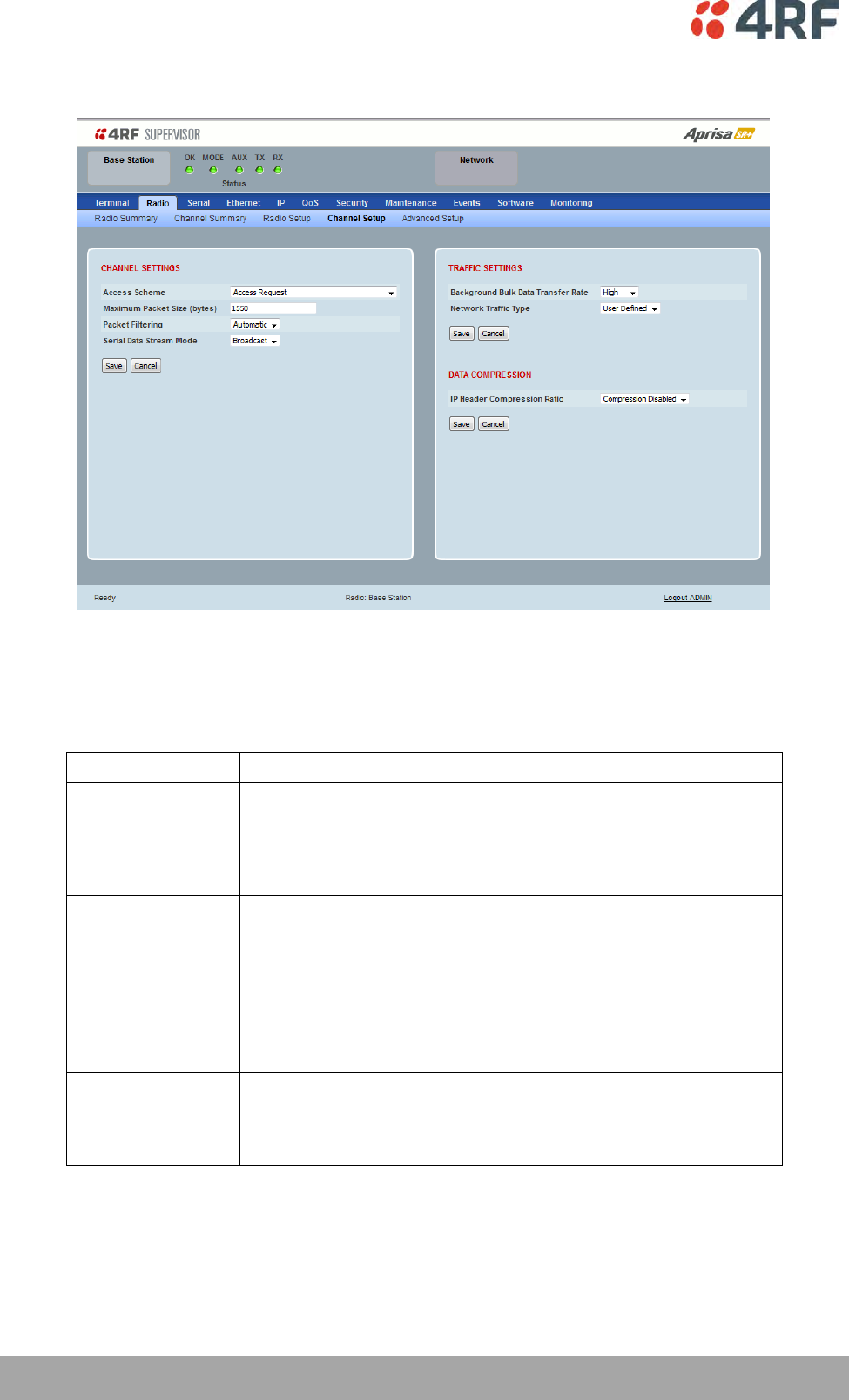
114 | Managing the Radio
Aprisa SR+ User Manual 1.6.0 PO
Radio > Channel Setup
CHANNEL SETTINGS
Access Scheme
This parameter sets the Media Access Control (MAC) used by the radio for over the air communication.
Option
Function
Access Request
Channel access scheme where the base station controls the
communication on the channel. Remotes ask for access to the
channel, and the base station grants access if the channel is not
occupied. This mode is a general purpose access method for high
and low load networks.
Access Request (full
duplex)
Used on a network with full duplex base station hardware and half
duplex repeaters / remotes.
A full duplex version of Access Request channel access scheme
where the base station controls the communication on the
channel. Remotes ask for access to the channel, and the base
station grants access if the channel is not occupied. The base
station can send traffic during remote transmit, exploiting the base
station full duplex capabilities.
Listen Before Send
without
Acknowledgement
Channel access scheme where network elements listen to ensure
the channel is clear, before trying to access the channel. This
mode is optimized for low load networks and repeated networks.
Acknowledgements are disabled.

Managing the Radio | 115
Aprisa SR+ User Manual 1.6.0 PO
Listen Before Send
with
Acknowledgement
Channel access scheme where network elements listen to ensure
the channel is clear, before trying to access the channel. This
mode is optimized for low load networks and repeated networks.
With Acknowledgement, unicast requests from the remote station
are acknowledged by the base station to ensure that the
transmission has been successful. If the remote station does not
receive an acknowledgement, then random back-offs are used to
reschedule the next transmission.
Enabling acknowledgments increases reliability of transport but
reduces available channel capacity so if application has the
capability to handle lost or duplicate messages, the Access Scheme
should be set to Listen Before Send without Acknowledgement.
Point To Point (Half
Duplex)
Channel access scheme used for Mirrored Bits ®.
The default setting is Access Request.
Repeater
This parameter sets the Media Access Control (MAC) used by the radio for over the air communication.

116 | Managing the Radio
Aprisa SR+ User Manual 1.6.0 PO
Maximum Packet Size (Bytes)
This parameter sets the maximum over-the-air packet size in bytes. A smaller maximum Packet Size is
beneficial when many remote stations or repeater stations are trying to access the channel. The default
setting is 1550 bytes.
As radios dispatched from the factory have a Packet Size set to the maximum value of 1550 bytes, if a new
radio is installed in an existing network, the Packet Size must be changed to ensure it is the same value
for all radios in the network. The new radio will not register an existing network if the Packet Size is not
the same as the other radios in the network.
This packet size includes the wireless protocol header and security payload (0 to 16 bytes). The length of
the security header depends on the level of security selected.
When the security setting is 0, the maximum user data transfer over-the-air is 1516 bytes.
When encryption is enabled, the entire packet of user data (payload) is encrypted. If authentication is
being used, the security frame will be added (up to 16 bytes). The wireless protocol header is then added
which is proprietary to the Aprisa SR+. This is not encrypted.
Packet Filtering
Each Aprisa SR+ radio can filter packets not destined for itself. The Packet Filtering parameter controls
this functionality.
In an Aprisa SR+ network, all communication from remote stations is destined for the base station in the
Aprisa SR+ network communication protocol. In a repeater or base-repeater network, a remote station will
send a message to the base station. The repeater station will receive this and then repeat the message.
The repeated message will then be received by the base station. Other remote stations connected to the
repeater station will receive this message and depending on the Packet Filtering parameter, either
forward this packet or discard it.
This filtering capability can provide the ability for remote stations to communicate with each other (peer
to peer communication) when connected to a repeater station or to a base-repeater station, particularly
useful in the event of losing communication with a SCADA Master, assuming the Aprisa SR+ network is still
operational. For example, to create peer to peer communication between two remotes in a network with
a base-repeater, the base-repeater packet filtering setting is set to 'Automatic' and the two remotes
packet filtering setting is set to 'Disabled'.
Note: IP Header Compression must be disabled for this feature to operate correctly (see ‘IP Header
Compression Ratio’ on page 119).
Option
Function
Disabled
Every packet received by the radio will be forwarded to the
relevant interface.
Automatic
The radio will filter (discard) packets not destined for itself
according to the Aprisa SR+ traffic protocols
The default setting is Automatic.
Note: The Aprisa SR+ network is transparent to the protocol being transmitted; therefore the Packet
Filtering parameter is based on the Aprisa SR+ addressing and network protocols, not the user (SCADA,
etc.) traffic protocols.
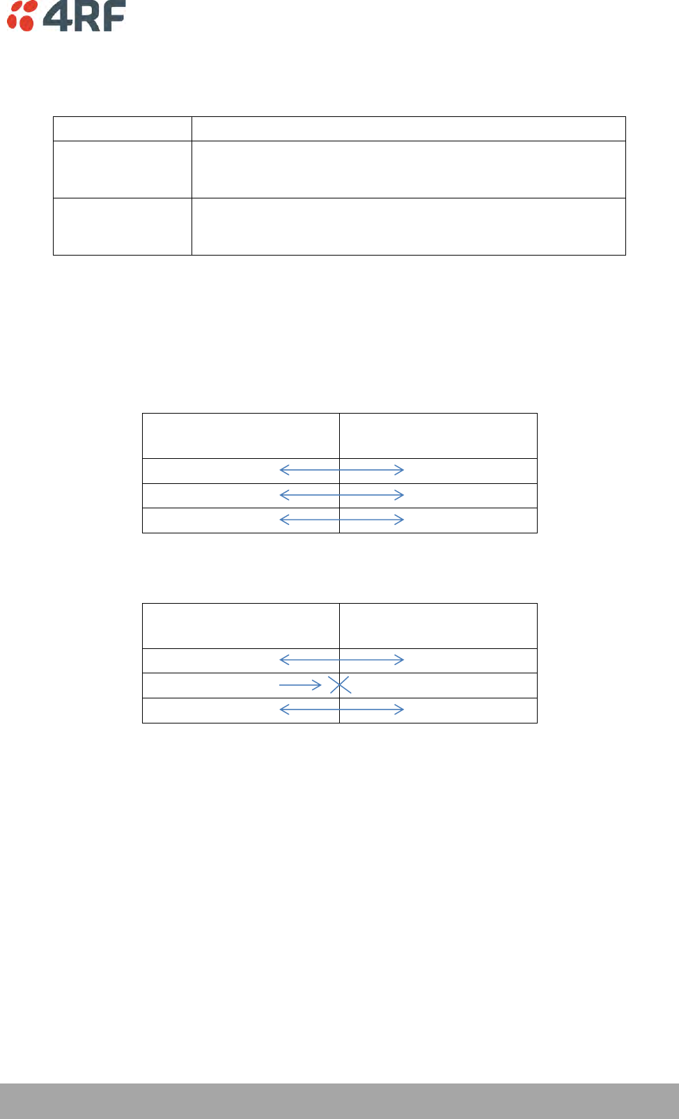
Managing the Radio | 117
Aprisa SR+ User Manual 1.6.0 PO
Serial Data Stream Mode
This parameter controls the traffic flow in the radio serial ports.
Option
Function
Broadcast
Serial port traffic from the network is broadcast on all serial ports
on this radio. This will include the RS-232 port derived from the
USB port.
Segregate
Serial port traffic from the network from a specific port number is
directed to the respective serial port only (see Segregated Port
Directions).
The default setting is Broadcast.
Segregated Port Directions
If the base station and the remote radios were deployed with the same Data Port product option e.g. all
radios were purchased as 2E2S (two Ethernet ports and two Serial ports), serial port traffic from the
network from a specific port number is directed to the respective serial port on all radios.
2E2S
Port Number
2E2S
Port Number
1
1
2
2
USB
USB
But if the base station and the remote radios were deployed with different Data Port product options, the
following table shows how serial port traffic is directed:
2E2S
Port Number
3E1S
Port Number
1
1
2
NA
USB
USB
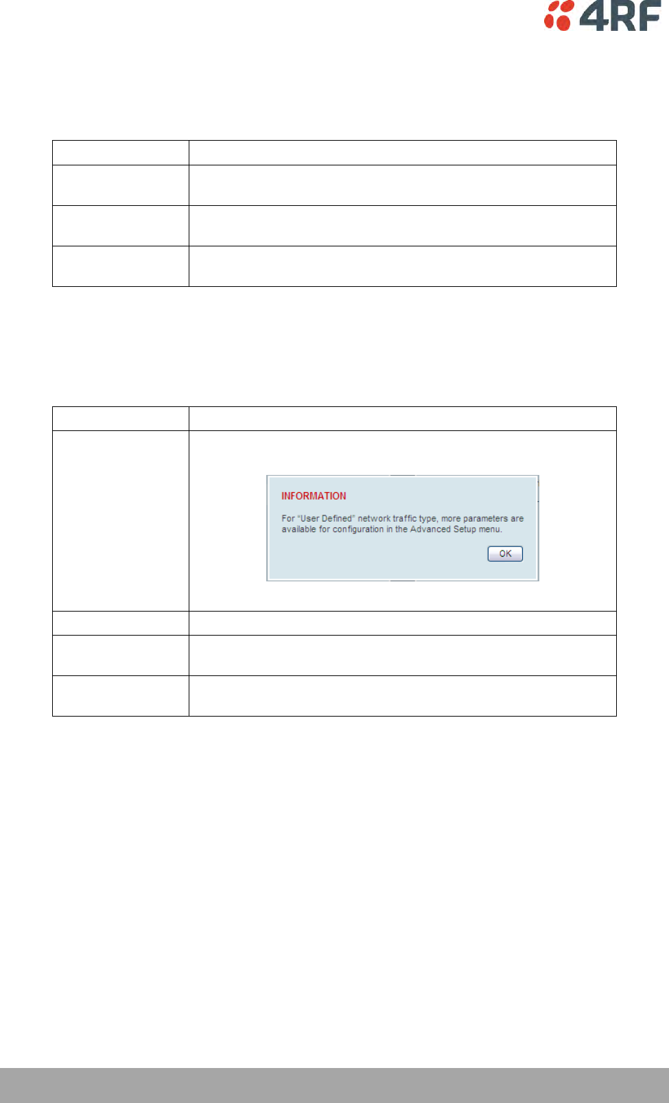
118 | Managing the Radio
Aprisa SR+ User Manual 1.6.0 PO
TRAFFIC SETTINGS
Background Bulk Data Transfer Rate
This parameter sets the data transfer rate for large amounts of management data.
Option
Function
High
Utilizes more of the available capacity for large amounts of
management data. Highest impact on user traffic.
Medium
Utilizes a moderate of the available capacity for large amounts of
management data. Medium impact on user traffic.
Low
Utilizes a minimal of the available capacity for large amounts of
management data. Lowest impact on user traffic.
The default setting is high.
Network Traffic Type
This parameter optimizes the channel settings for the predominant traffic type.
Option
Function
User Defined
Allows the user to define the channel settings (see ‘Radio >
Advanced Setup’ on page 120).
Serial Only
Optimizes the channel settings for the predominantly serial traffic.
Ethernet Only
Optimizes the channel settings for the predominantly Ethernet
traffic.
Mixed
Optimizes the channel settings for a mix of Ethernet and serial
traffic.
The default setting is Mixed.
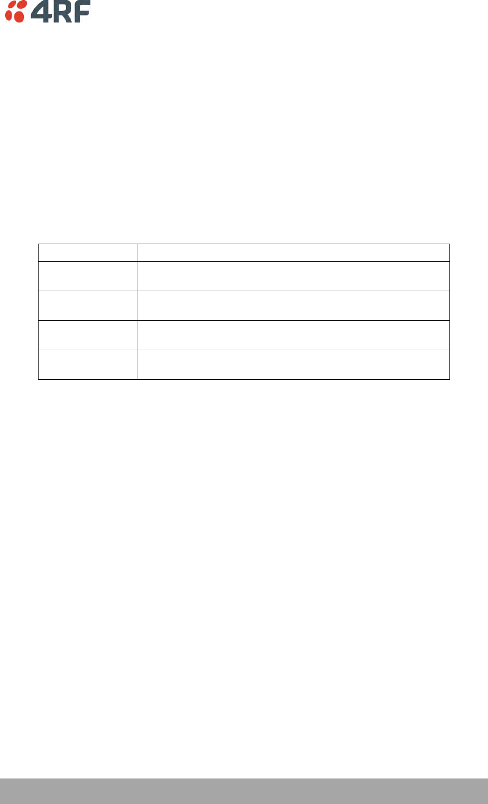
Managing the Radio | 119
Aprisa SR+ User Manual 1.6.0 PO
DATA COMPRESSION
IP Header Compression Ratio
The IP Header Compression implements TCP/IP ROHC v2 (Robust Header Compression v2. RFC4995,
RFC5225, RFC4996) to compress the IP header. IP header compression allows for faster point-to-point
transactions, but only in a star network.
IP Header Compression module comprises of two main components, compressor and decompressor. Both
these components maintain some state information for an IP flow to achieve header compression.
However, for reasons like packet drops or station reboots this state information can go out of sync
between the compressor and decompressor resulting in compression and/or decompression failure
resulting in loss of packets.
The compression ratio controls the rate at which compressor and decompressor synchronize state
information with each other. Frequent synchronization results in reduced ratio.
Option
Function
Compression
Disabled
Disables IP header compression.
High
State information is synchronized less frequently thus achieving
the best compression ratio.
Medium
State information is synchronization more frequently than ‘High’
setting but less frequently than ‘Low’ setting.
Low
State information is synchronized frequently thus reducing the
compression ratio.
The default setting is High.
When IP Header Compression is enabled, it is important that the Network Radius is set correctly. If it was
incorrectly set to 1, header compression could not be interpreted by radius 2 radios.
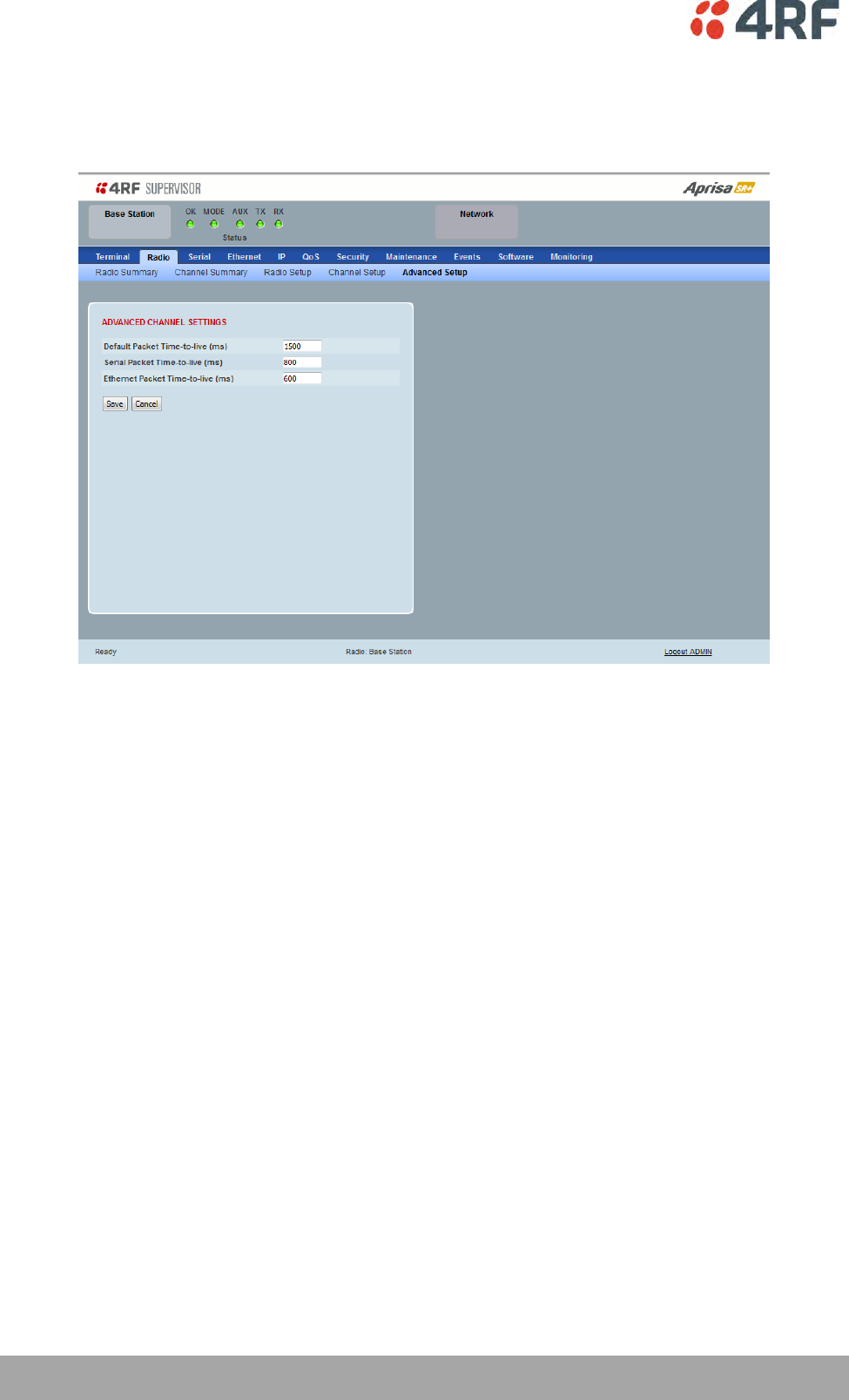
120 | Managing the Radio
Aprisa SR+ User Manual 1.6.0 PO
Radio > Advanced Setup
This page is only visible when the Channel Setup > Network Traffic Type is set to User Defined.
ADVANCED CHANNEL SETTINGS
Default Packet Time to Live (ms)
This parameter sets the default time a packet is allowed to live in the system before being dropped if it
cannot be transmitted over the air. It is used to prevent old, redundant packets being transmitted through
the Aprisa SR+ network. The default setting is 1500 ms.
In the case of serial poll SCADA networks such as MODBUS and IEC 60870.50.101, it is important to ensure
the replies from the RTU are in the correct sequence and are not timed out replies from Master requests.
If the TTL value is too long, the SCADA master will detect sequence errors.
It is recommended to use a TTL which is half the serial SCADA timeout. This is commonly called the ‘scan
timeout’ or ‘link layer time out’ or ‘retry timeout’.
When using TCP protocols, a TTL of 1500 ms is recommended because a TCP re-transmission usually occurs
after approximately 3 seconds.
In SCADA networks which use both serial and Ethernet, it is recommended that the TTL is set to half the
serial SCADA timeout for serial remotes, and 1500 ms for Ethernet (TCP) remotes. For example, if the
serial SCADA timeout is 1000 ms, a remote radio which is connected to the serial RTU should be set to
500 ms, a remote radio which is connected to an Ethernet (TCP) RTU should have a 1500 ms timeout.
In this case, the base station TTL should be set to 1500 ms as well; or whichever is the longer TTL of serial
or Ethernet.
The default packet Time To Live (1500 ms) can cause the first packet sent to be lost when exiting sleep
mode. The same will occur when exiting Access Request MAC idle mode if the power save ratio is set to
maximum. The packet Time To Live is extended if those packets originate during the power save wakeup
or the sleep exit time.

Managing the Radio | 121
Aprisa SR+ User Manual 1.6.0 PO
Serial Packet Time to Live (ms)
This parameter sets the time a serial packet is allowed to live in the system before being dropped if it
cannot be transmitted over the air. The default setting is 800 ms.
Ethernet Packet Time to Live (ms)
This parameter sets the time an Ethernet packet is allowed to live in the system before being dropped if it
cannot be transmitted over the air. The default setting is 600 ms.
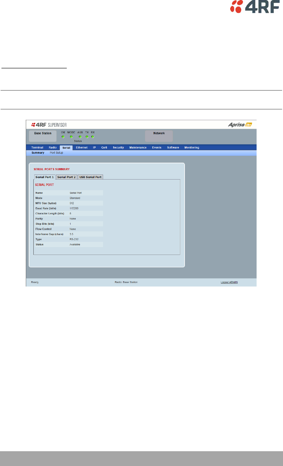
122 | Managing the Radio
Aprisa SR+ User Manual 1.6.0 PO
Serial
Serial > Summary
RS-232 Hardware Ports
This page displays the current settings for the serial port parameters.
Note: This screen is dependent on the Data Port product option purchased (see ‘Data Interface Ports’ on
page 329). The Data Port product option shown is a 2E2S – two Ethernet ports and two Serial ports
See ‘Serial > Port Setup’ on page 124 for configuration options.
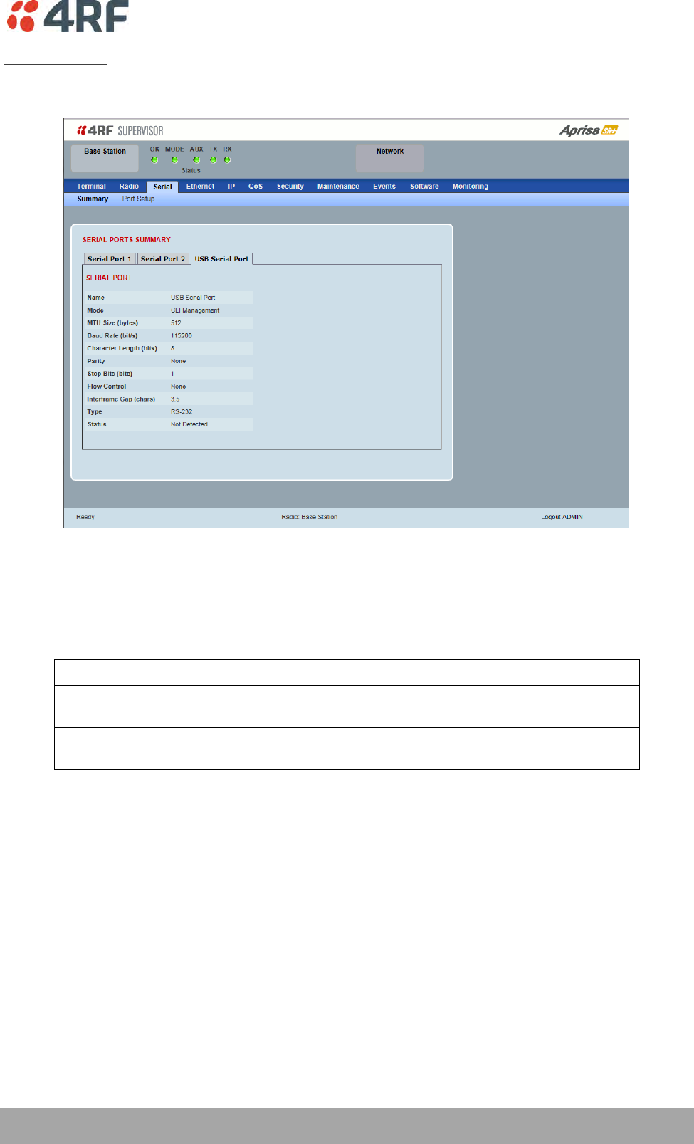
Managing the Radio | 123
Aprisa SR+ User Manual 1.6.0 PO
USB Serial Ports
This page displays the current settings for the USB serial port parameters.
Type
This parameter displays the Serial Port interface type.
If the Name is USB Serial Port:
Option
Function
RS-232
Indicates that a USB to RS-232 serial converter is plugged into the
radio.
RS-485
Indicates that a USB to RS-485 serial converter is plugged into the
radio.
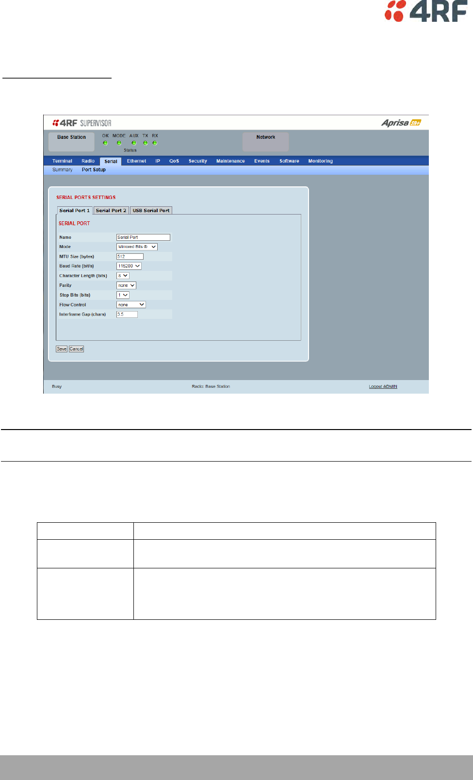
124 | Managing the Radio
Aprisa SR+ User Manual 1.6.0 PO
Serial > Port Setup
RS-232 Hardware Ports
This page provides the setup for the serial port settings.
SERIAL PORTS SETTINGS
Note: This screen is dependent on the Data Port product option purchased (see ‘Data Interface Ports’ on
page 329). The Data Port product option shown is a 2E2S – two Ethernet ports and two Serial ports
Name
This parameter sets the port name which can be up to 32 characters.
Option
Function
Serial Port
This is the normal RS-232 serial ports provided with the RJ45
connector.
USB Serial Port
This is the optional RS-232 / RS-485 serial port provided with the
USB host port connector with a USB to RS-232 / RS-485 RJ45
converter cable (see ‘USB RS-232 / RS-485 Serial Port’ on page
353).

Managing the Radio | 125
Aprisa SR+ User Manual 1.6.0 PO
Mode
This parameter defines the mode of operation of the serial port. The default setting is Standard.
Option
Function
Disabled
The serial port is not required.
Standard
The serial port is communicating with serial ports on other
stations.
Bit Oriented
This mode allows support for legacy protocols that are not
compatible with standard UARTs (see ‘Bit Oriented’ on page 126).
Mirrored Bits ®
Mirrored Bits® is a serial communications protocol used to
exchange internal logic status messages directly between relays
and devices used in line protection, remote control and
monitoring, relay remote tripping, sectionalizing and other such
applications. The protocol is often described as a relay-to-relay
communications technology.
Terminal Server
A base station Ethernet port can communicate with both Ethernet
ports and serial ports on remote stations.
RS-232 traffic is encapsulated in IP packets (see ‘Serial > Port
Setup’ Terminal Server on page 131).
SLIP
IP packets are encapsulated over RS-232 interface port (see ‘Serial
> Port Setup’ Serial Line Interface Protocol (SLIP)’ on page 134).
MTU Size (bytes)
This parameter sets the size of the packet in bytes received before it is transmitted if an inter-frame gap
is not detected. The default setting is 512 bytes.
Baud Rate (bit/s)
This parameter sets the baud rate to 300, 600, 1200, 2400, 4800, 9600, 19200, 38400, 57600 or 115200
bit/s. The default setting is 115200 bit/s.
Character Length (bits)
This parameter sets the character length to 7 or 8 bits. The default setting is 8 bits.
Parity
This parameter sets the parity to Even, Odd or None. The default setting is None.
Stop Bits (bits)
This parameter sets the number of stop bits to 1 or 2 bits. The default setting is 1 bit.

126 | Managing the Radio
Aprisa SR+ User Manual 1.6.0 PO
Flow Control
This parameter sets the flow control of the serial port. The default setting is Disabled.
Option
Function
None
The Aprisa SR+ radio port (DCE) CTS is in a permanent ON (+ve)
state.
This does not go to OFF if the radio link fails.
CTS-RTS
CTS / RTS hardware flow control between the DTE and the Aprisa
SR+ radio port (DCE) is enabled.
If the Aprisa SR+ buffer is full, the CTS goes OFF.
In the case of radio link failure the signal goes to OFF (-ve) state.
In terminal server mode, the serial packet is no different from an Ethernet packet and travels through
various packet queues before being transmitted over the air. Thus, the serial flow control has no affect in
terminal server mode.
Inter-Frame Gap (chars)
This parameter defines the gap between successive serial data frames. It is used to delimit the serial data
to define the end of a packet. The Inter-Frame Gap limits are 0 to 20 chars in steps of 0.1 char. The
default setting is 3.5 chars.
Bit Oriented
This menu item is only applicable if the serial port has an operating mode of Bit Oriented.
This mode allows support for legacy protocols that are not compatible with standard UARTs. Examples are
VAN COMM, REDAC and CONITEL, although others will work as well.
The limitations of this new mode are:
The MTU must be configured larger than the inter-frame gap
The maximum baud rate is 1200 bit/s
The inter-frame gap must be configured to the length of a packet in the protocol being used. This
is 14 for VAN COMM, and 4 for REDAC and CONITEL)
Only supported on one serial port at a time
Not supported on USB serial port.

Managing the Radio | 127
Aprisa SR+ User Manual 1.6.0 PO
Mirrored Bits®
Introduction
Mirrored Bits® is a serial communications protocol used to exchange internal logic status messages directly
between relays and devices used in line protection, remote control and monitoring, relay remote tripping,
sectionalizing and other such applications.
The protocol relies on near constant transmission of status bytes between the devices. It can only tolerate
small delays between receipts of packets.
The protocol provides alarms states to monitor and report on radio channel performance. If a receiving
device does not receive a status packet within a predefined time then it asserts an ‘instantaneous channel
monitor’ error (ROK), this error clears as soon as the next status packet is received.
There are two more significant errors RBAD (ROK dropout for settable time) and CBAD (long term channel
unavailability exceeding a settable threshold) that will be asserted if more extensive delays occur or the
communications channel is lost.
The trigger or time period for asserting ROK varies between devices. Typically the ROK error state is
asserted if a receiving device does not receive a packet for a period > than 3 x the period taken to
transmit a packet.
When optimizing for Mirrored Bits® operation the target is to present a radio channel that does not result
in ROK triggers occurring. Individual networks may be tolerant to occasional ROK alarms states if
configured to make use of the more significant alarms
Optimization
Typically Full Duplex radio communications are required however Aprisa SR+ has been optimized to
support Mirrored Bits® in a narrow channel licensed Half Duplex radio channel.
4RF has introduced a channel access scheme optimized for Mirrored Bits® support between two devices.
Error free transport of the protocol can be achieved through specific serial traffic configuration settings,
which are dependent on the radio RF configuration, Mirrored Bits® devices and network characteristics.
Under some scenarios limited Ethernet transport may be supported without impacting Mirrored Bits®
operation. If the network can tolerate occasional ROK errors Ethernet support may be increased. The level
of impact on Mirrored Bits® is related to radio settings and the specifics of the Ethernet traffic including
size and frequency of the Ethernet packets.
When attempting to configure the radios to support new devices or varying network requirements a
standard configuration is used for the radios and the following two key serial data parameters are
adjusted:
Inter Frame Gap (IFG) – used to detect new packets on the serial input to the radio
Maximum Transmission Unit (MTU) – used to define the over the air (OTA) packet size
To date, 4RF has lab tested and confirmed operation with the follow SEL Mirrored Bits® devices. Contact
4RF for preferred configuration:
2411 PAC (Programmable Automation Controller)
2505 series remote I/O modules
321 series relays
4RF is working with customers to confirm support for other devices as they are identified. The remainder
of this document details the configuration settings and general process to optimize the radio to support
additional devices, in addition to listing expected latencies under different configurations.

128 | Managing the Radio
Aprisa SR+ User Manual 1.6.0 PO
General Configuration
The configurations and process are aligned with a 2505 series remote I/O module device with serial baud
rate of 9600. As a ‘fast’ Mirrored Bits® device it is considered a good start point for optimization. For
other baud rates please refer to the table in Initial Setup for Mirrored Bits® Support on page 129 for initial
MTU and IFG settings.
The following are the recommended RF configurations and serial data configuration settings and to
optimize the performance over Aprisa SR+ radios.
Recommended RF configurations are:
Radio->Channel Setup->Serial Data Stream Mode to ‘Segregate’
Radio->Channel Setup->Access Scheme to Point To Point (Half Duplex)
Radio->Channel Setup->Network Traffic Type to ‘Serial Only’
Radio > Radio Setup > Channel size – set to meet license requirements (the wider the better for
performance)
Radio > Radio Setup > Modulation – 64 QAM low
Serial data port variable parameters
Two key serial port parameters will be adjusted during optimization. The following initial values have
been determined as a suitable for the SEL 2505 device which is the fastest device 4RF has lab tested. It is
a suitable start point to carry out optimization for other devices.
Inter Frame Gap – initially set to 0.2
IFG is dependent on serial line baud rate only
The Mirrored Bits® protocol is essentially timed to a base clock, the slower the baud rate the
longer the period to transmit a packet resulting in less time between packets
A low baud rate is ideal as it increase the time period before a ROK error will occur as this is
dependent on serial packet transmission time
The minimum baud rate currently proven to provide reliable communications is 9600 bit, with this
rate an IFG of 0.2 is required to be used
With the 2505 device the IFG increases with increases in serial baud rate, while easier to detect
gaps the ROK error period is reduced
MTU – initially set to 32 bytes
Dependent on serial line baud rate, channel size, modulation, security settings, intended traffic
mix and all other settings that influence OTA speed and capacity available for external traffic
MTU affects latency, if a large MTU then the radio will ‘wait’ for the number of bytes before
sending the packet OTA
Ideally a low MTU will be used – the minimum needs to support the various settings above and
intended mix of traffic
MTU can be changed in steps of +/- 8 when trying different configurations
Refer table in section 5 for start point of MTU based on channel size, modulation and serial baud
rate, this assumes the general radio settings as above
Increase by 8 for new devices or in attempt to support some Ethernet or other services

Managing the Radio | 129
Aprisa SR+ User Manual 1.6.0 PO
Initial Setup for Mirrored Bits® Support
The MTU can be adjusted up or down in steps of 8 bytes
Increase by 8 bytes if Mirrored Bits® is not running without alarms or ROK assertions
Decrease by 8 bytes if Mirrored Bits® is running error free, the target is to find the smallest MTU
for reliable transport
If reliable Mirrored Bits® communications cannot be achieved after increasing the MTU by 10 steps or 80
bytes, then the following CLI commands can be used to extract low level packet information from the
radio.
This information can be forwarded to 4RF to determine what is occurring and identify alternate
configurations.
Configure Radio / Mirrored Bits® equipment for 9600 baud rate
Connect Mirrored Bits® equipment to one of the serial ports and start traffic
Ensure no management traffic or other services are connected to the Ethernet or Serial ports
Login to the radio CLI as ‘admin’ and execute ‘debug set 2 5’ -> there will be continuous scrolling
information
Screen capture one page of the scrolling information to send to 4RF
Remove serial cable and execute ‘debug clear 2 5’ via the CLI to clear the debug routine,
alternatively reboot the radio
Note if the serial baud rate intended to be used is not 9600 then repeat for each different rate
and clearly identify the screen prints by baud rate before forwarding to 4RF
Note there are additional low level configurations which can improve performance. 4RF will detail these if
required based on the information received.
Additional Setup for Improved Latency or Additional Services
Once reliable Mirrored Bits® communications has been achieved experimentation can be undertaken to
reduce latencies or provide support for additional services such as Ethernet based SCADA polling.
Increasing the MTU will impact latency for each packet (refer to table in section 4). A point may be
reached where the gaps between individual packets are too high and the Mirrored Bits® ROK or other
alarms will assert.
Increasing the MTU allows some ‘space’ in each packet for additional data from the second serial port or
the Ethernet ports.
Support for Ethernet is highly dependent on the size and frequency of packets being sent. A level of trial
and error is required. At the very narrow channel sizes and OTA data rates support may be limited
however with wider channels and higher OTA data rates some services may be supported (such as polling).
It should be noted that if the Mirrored Bits® devices or network manager can accept occasional ROK
assertions then there is more flexibility for other services.
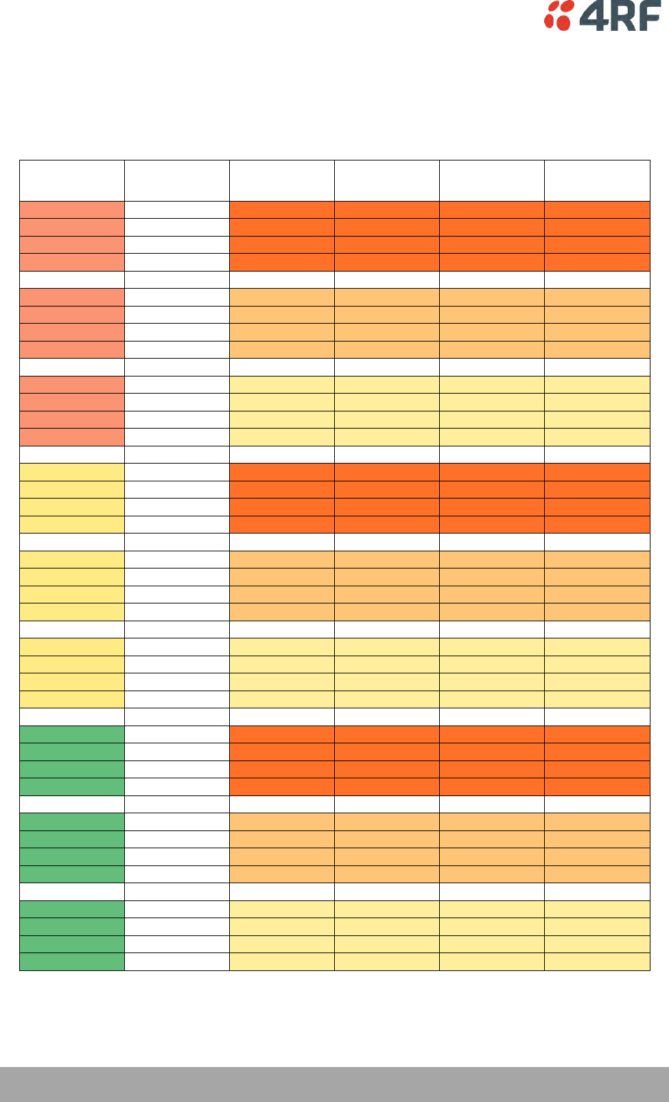
130 | Managing the Radio
Aprisa SR+ User Manual 1.6.0 PO
Baud rate and Latency Table
The following table is arranged by serial baud rate followed by Aprisa SR+ channel size and modulation. It
lists the optimized MTU and IFG and resulting latency for the SEL 2505 device, one of the faster devices
available so serves as an ideal starting point when introducing new devices. It is recommended that initial
testing is carried out with one step size higher (8) on MTU.
Serial Baud
Rate
Modulation
Channel Size
Minimum MTU
Size
IFG
SEL 2505
One Way
Latency (ms)
9600
64 QAM Low
50
8
0.2
20.0
9600
16 QAM Low
50
16
0.2
-
9600
QPSK
50
16
0.2
-
9600
QPSK Low
50
24
0.2
42.5
9600
64 QAM Low
25
16
0.2
40.0
9600
16 QAM Low
25
24
0.2
-
9600
QPSK
25
24
0.2
-
9600
QPSK Low
25
32
0.2
62.5
9600
64 QAM Low
12.5
24
0.2
60.0
9600
16 QAM Low
12.5
40
0.2
-
9600
QPSK
12.5
40
0.2
-
9600
QPSK Low
12.5
64
0.2
125.0
19200
64 QAM Low
50
16
0.5
25.0
19200
16 QAM Low
50
24
0.5
-
19200
QPSK
50
24
0.5
-
19200
QPSK Low
50
24
0.5
-
19200
64 QAM Low
25
32
0.5
50.0
19200
16 QAM Low
25
48
0.5
-
19200
QPSK
25
56
0.5
-
19200
QPSK Low
25
56
0.5
-
19200
64 QAM Low
12.5
56
0.5
85.0
19200
16 QAM Low
12.5
88
0.5
-
19200
QPSK
12.5
not supported
0.5
-
19200
QPSK Low
12.5
not supported
0.5
-
38400
64 QAM Low
50
24
3
40.0
38400
16 QAM Low
50
24
3
-
38400
QPSK
50
32
3
-
38400
QPSK Low
50
40
3
62.5
38400
64 QAM Low
25
40
3
62.5
38400
16 QAM Low
25
72
3
-
38400
QPSK
25
76
3
-
38400
QPSK Low
25
not supported
3
-
38400
64 QAM Low
12.5
82
3
112.5
38400
16 QAM Low
12.5
not supported
3
-
38400
QPSK
12.5
not supported
3
-
38400
QPSK Low
12.5
not supported
3
-
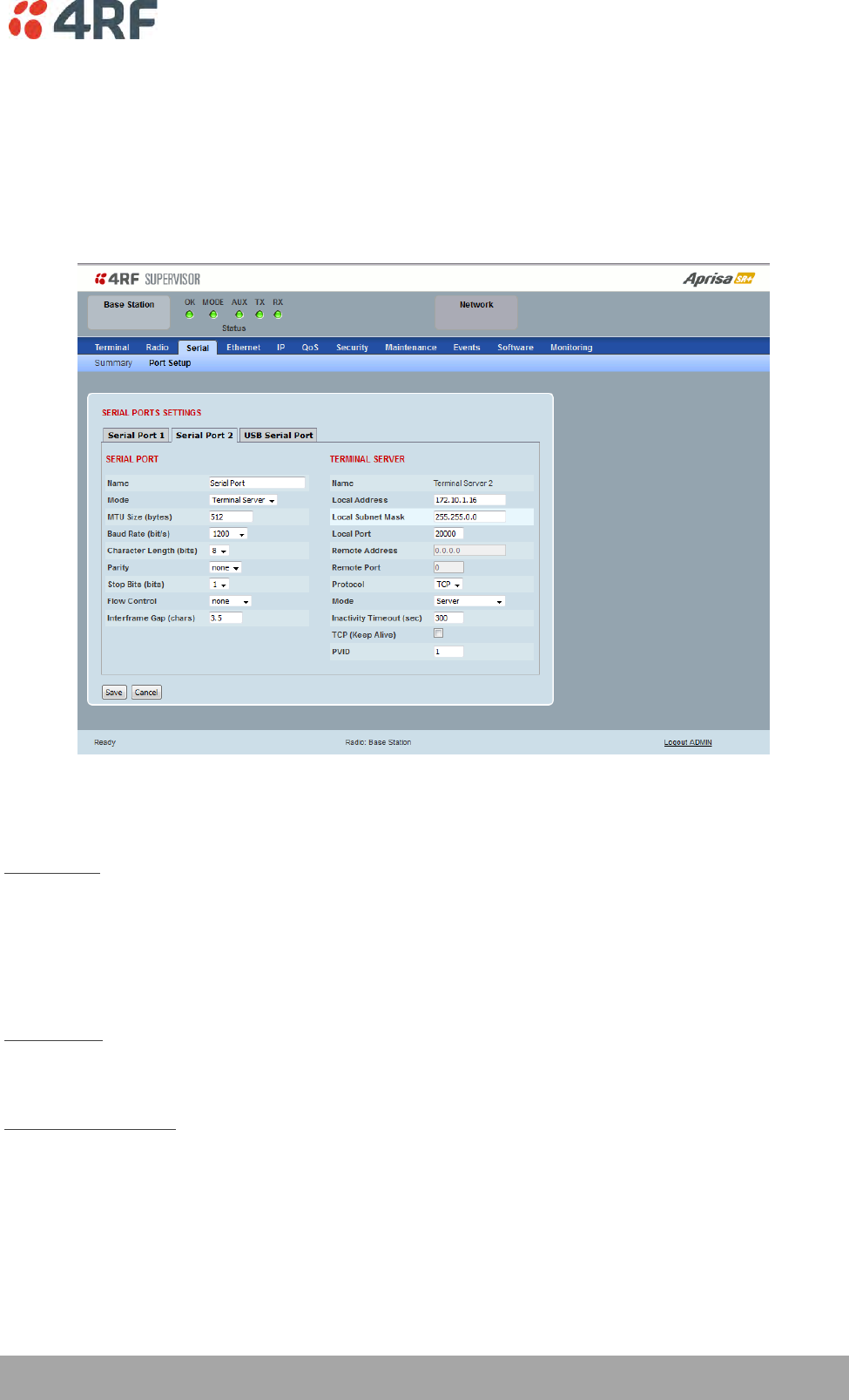
Managing the Radio | 131
Aprisa SR+ User Manual 1.6.0 PO
Terminal Server
This menu item is only applicable if the serial port has an operating mode of Terminal Server.
The Terminal Server operating mode provides encapsulation of serial data into an IP packet (over TCP or
UDP).
A server connected to a base station Ethernet port can communicate with all remote station Ethernet
ports and serial ports.
Local Address
This parameter sets the serial Terminal Server local IP address.
Bridge Mode
The local IP address can be the same as the radio's configured IP address or the Virtual IP address for
protected stations. If it is not the above, then it must be an IP address from a network different from the
radio's network.
Note that the Terminal Server local IP address settings can be the same for other terminal servers in the
radio.
Router Mode
The local IP address must be the same as port 1 (management IP address) of the radio’s configured port IP
addresses or the Virtual IP address for protected stations.
Gateway Router Mode
The local IP address must be the same as the radio's configured IP address or the Virtual IP address for
protected stations.

132 | Managing the Radio
Aprisa SR+ User Manual 1.6.0 PO
Local Port
This parameter sets the TCP or UDP port number of the local serial port.
The valid port number range is less than or equal to 49151 but with exclusions of 0, 5445, 6445, 9930 or
9931. The default setting is 20000.
The user is responsible for ensuring that there is no conflict on the network.
Remote Address
This parameter sets the IP address of the server connected to the base station Ethernet port.
Remote Port
This parameter sets the TCP or UDP port number of the server connected to the base station Ethernet
port. The default setting is 0.
Protocol
This parameter sets the L4 TCP/IP or UDP/IP protocol used for terminal server operation. The default
setting is TCP.
Mode
This parameter defines the mode of operation of the terminal server connection. The default setting is
Client and Server.
Option
Function
Client
The radio will attempt to establish a TCP connection with the
specified remote unit. Generally, this setting is for the base station
with an Ethernet connection to the SCADA master.
Server
The radio will listen for a TCP connection on the specified local
port. Generally, this setting is for the remote station with a serial
connection to the RTU.
Data received from any client shall be forwarded to the associated
serial port while data received from that serial port shall be
forwarded to every client with an open TCP connection.
If no existing TCP connections exist, all data received from the
associated serial port shall be discarded.
Client and Server
The radio will listen for a TCP connection on the specified local
port and if necessary, establish a TCP connection with the
specified remote unit. Generally, this setting is used for the
remote station but it should be used carefully as two connections
might be established with the base station.
Data received from any client shall be forwarded to the associated
serial port while data received from that serial port shall be
forwarded to every client with an open TCP connection.
Inactivity Timeout (seconds)
This specifies the duration (in seconds) to automatically terminate the connection with the remote TCP
server if no data has been received from either the remote TCP server or its associated serial port for the
duration of the configured inactivity time.

Managing the Radio | 133
Aprisa SR+ User Manual 1.6.0 PO
TCP Keep Alive
A TCP keep alive is a message sent by one device to another to check that the link between the two is
operating, or to prevent the link from being broken.
If the TCP keep alive is enabled, the radio will be notified if the TCP connection fails.
If the TCP keep alive is disabled, the radio relies on the Inactivity Timeout to detect a TCP connection
failure. The default setting is disabled.
Note: An active TCP keep alive will generate a small amount of extra network traffic.
PVID
This parameter sets the PVID (port VLAN ID) for each of the terminal servers on the radio.
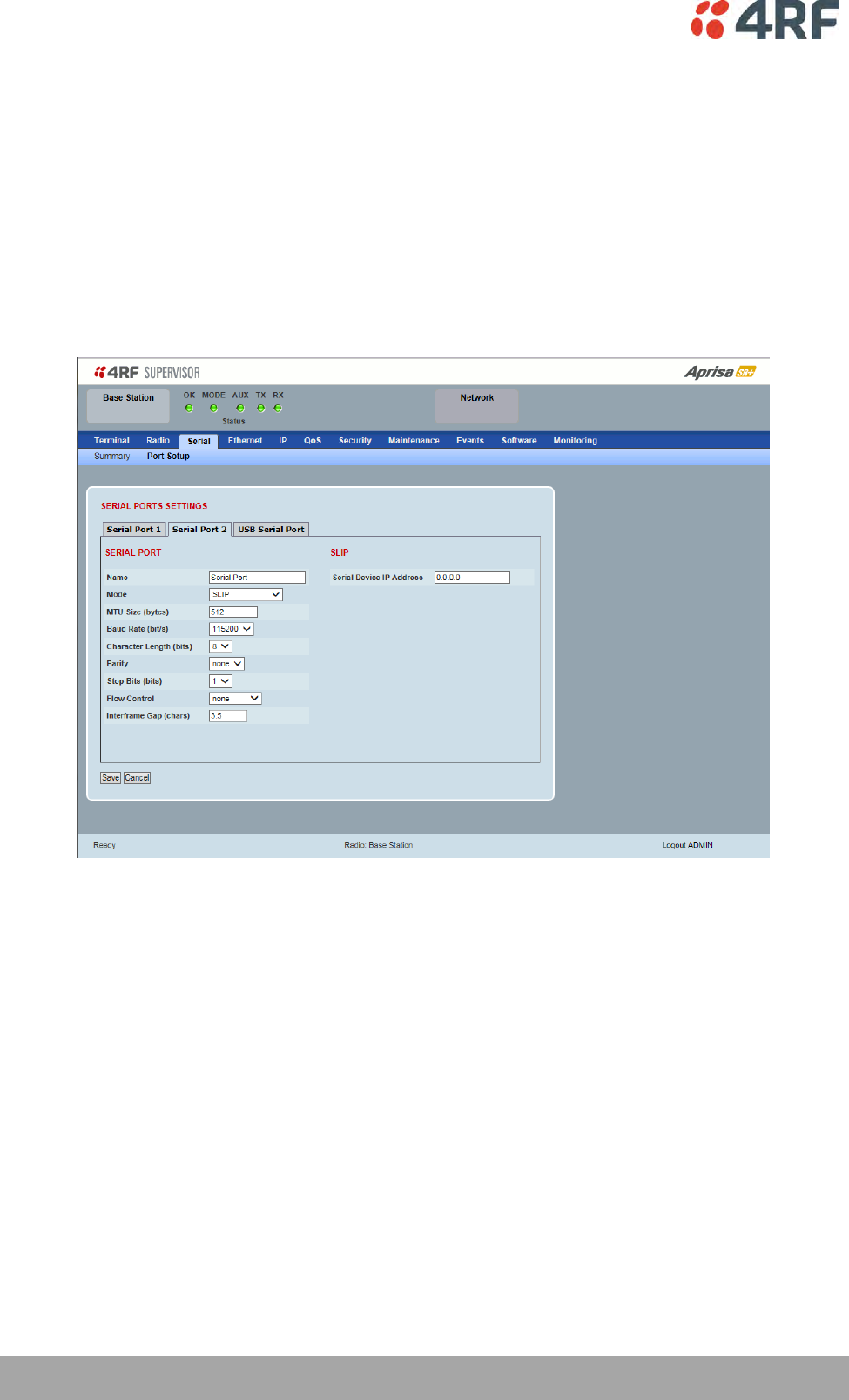
134 | Managing the Radio
Aprisa SR+ User Manual 1.6.0 PO
Serial Line Interface Protocol (SLIP)
This menu item is only applicable if the serial port has an operating mode of SLIP.
The SLIP operating mode provides IP packet encapsulation over RS-232 serial interface as per the SLIP
protocol RFC 1055.
A SLIP serial interface contains the IP address of the serially connected RTU as per the RTU/PLC SLIP
protocol. The SLIP interfaces on the remote radios can be part of the bridge network and can coexist and
operate with a mix of Ethernet interfaces, serial SLIP and terminal server interfaces.
As the RTU/PLC serial SLIP interface doesn't support MAC addresses, a remote or repeater radio SLIP
interface uses a proxy ARP function that returns its own MAC address for ARP requests based on the IP
address of the RTU/PLC SLIP interface.
Serial Device IP Address
This parameter sets the IP address of the RTU connected on the configured serial port.
Baud Rate (bit/s)
This parameter sets the baud rate to 1200, 2400, 4800, 9600, 19200, 38400, 57600 or 115200 bit/s. The
default setting is 115200 bit/s. The minimum supported baud rate is 1200 bit/s as SLIP will not work on
baud rates below 1200.
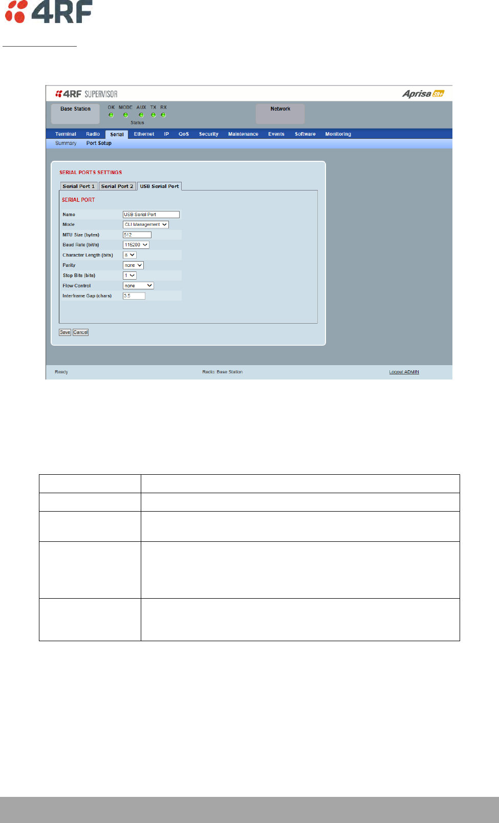
Managing the Radio | 135
Aprisa SR+ User Manual 1.6.0 PO
USB Serial Ports
This page provides the setup for the USB serial port settings.
SERIAL PORTS SETTINGS
Mode
This parameter defines the mode of operation of the serial port. The default setting is Disabled.
Option
Function
Disabled
The serial port is not required.
Standard
The serial port is communicating with serial ports on other
stations.
Terminal Server
A base station Ethernet port can communicate with both Ethernet
ports and serial ports on remote stations.
RS-232 traffic is encapsulated in IP packets (see ‘Serial > Port
Setup’ Terminal Server on page 131).
CLI Management
The USB host port is used to access the radio Command Line
Interface (CLI). A USB converter to RS-232 convertor will be
required to connect to a PC.
MTU Size (bytes)
This parameter sets the size of the packet in bytes received before it is transmitted if an inter-frame gap
is not detected. The default setting is 512 bytes.
Baud Rate (bit/s)
This parameter sets the baud rate to 300, 600, 1200, 2400, 4800, 9600, 19200, 38400, 57600 or 115200
bit/s. The default setting is 115200 bit/s.
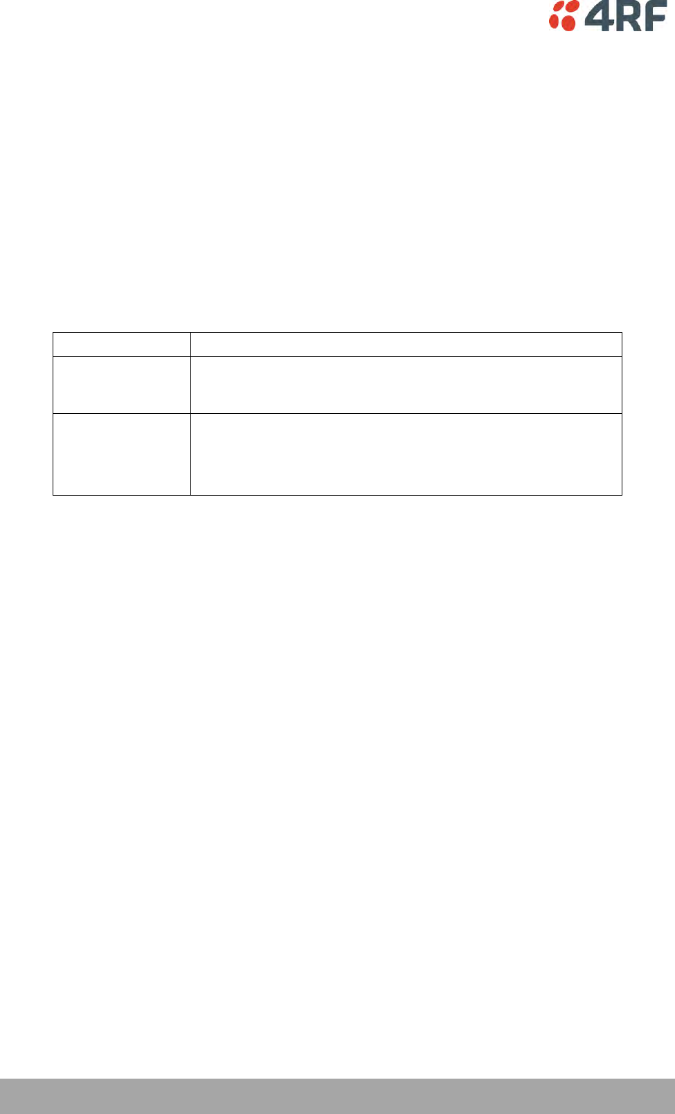
136 | Managing the Radio
Aprisa SR+ User Manual 1.6.0 PO
Character Length (bits)
This parameter sets the character length to 7 or 8 bits. The default setting is 8 bits.
Parity
This parameter sets the parity to Even, Odd or None. The default setting is None.
Stop Bits (bits)
This parameter sets the number of stop bits to 1 or 2 bits. The default setting is 1 bit.
Flow Control
This parameter sets the flow control of the serial port. The default setting is Disabled.
Option
Function
None
The Aprisa SR+ radio port (DCE) CTS is in a permanent ON (+ve)
state.
This does not go to OFF if the radio link fails.
CTS-RTS
CTS / RTS hardware flow control between the DTE and the Aprisa
SR+ radio port (DCE) is enabled.
If the Aprisa SR+ buffer is full, the CTS goes OFF.
In the case of radio link failure the signal goes to OFF (-ve) state.
In terminal server mode, the serial packet is no different from an Ethernet packet and travels through
various packet queues before being transmitted over the air. Thus, the serial flow control has no affect in
terminal server mode.
Inter-Frame Gap (chars)
This parameter defines the gap between successive serial data frames. It is used to delimit the serial data
to define the end of a packet. The Inter-Frame Gap limits are 0 to 20 chars in steps of 0.1 char. The
default setting is 3.5 chars.
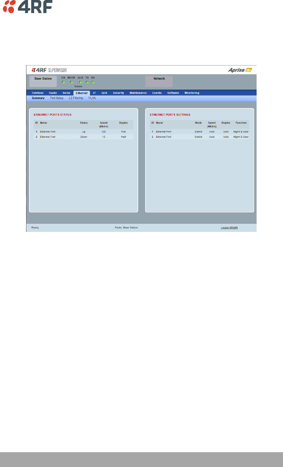
Managing the Radio | 137
Aprisa SR+ User Manual 1.6.0 PO
Ethernet
Ethernet > Summary
This page displays the current settings for the Ethernet port parameters and the status of the ports.
See ‘Ethernet > Port Setup’ for configuration options.
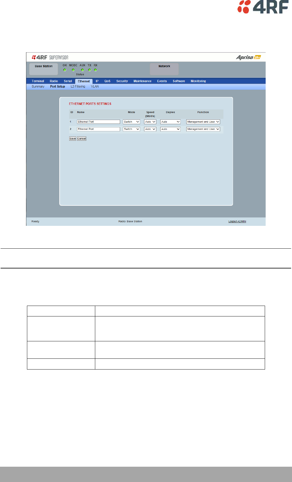
138 | Managing the Radio
Aprisa SR+ User Manual 1.6.0 PO
Ethernet > Port Setup
This page provides the setup for the Ethernet ports settings.
ETHERNET PORT SETTINGS
Note: This screen is dependent on the Data Port product option purchased (see ‘Data Interface Ports’ on
page 329). The Data Port product option shown is a 2E2S – two Ethernet ports and two Serial ports
Mode
This parameter controls the Ethernet traffic flow. The default setting is Standard.
Option
Function
Standard
Enables Ethernet data communication over the radio link but
Ethernet traffic is not switched locally between the two
Ethernet ports.
Switch
Ethernet traffic is switched locally between the two
Ethernet ports and communicated over the radio link
Disabled
Disables all Ethernet data communications.

Managing the Radio | 139
Aprisa SR+ User Manual 1.6.0 PO
Speed (Mbit/s)
This parameter controls the traffic rate of the Ethernet port. The default setting is Auto.
Option
Function
Auto
Provides auto selection of Ethernet Port Speed
10/100 Mbit/s
10
The Ethernet Port Speed is manually set to 10 Mbit/s
100
The Ethernet Port Speed is manually set to 100 Mbit/s
Duplex
This parameter controls the transmission mode of the Ethernet port. The default setting is Auto.
Option
Function
Auto
Provides auto selection of Ethernet Port duplex setting.
Half Duplex
The Ethernet Port is manually set to Half Duplex.
Full Duplex
The Ethernet Port is manually set to Full Duplex.
Function
This parameter controls the use for the Ethernet port. The default setting is Management and User.
Option
Function
Management Only
The Ethernet port is only used for management of the
network.
Management and User
The Ethernet port is used for management of the network
and User traffic over the radio link.
User Only
The Ethernet port is only used for User traffic over the radio
link.
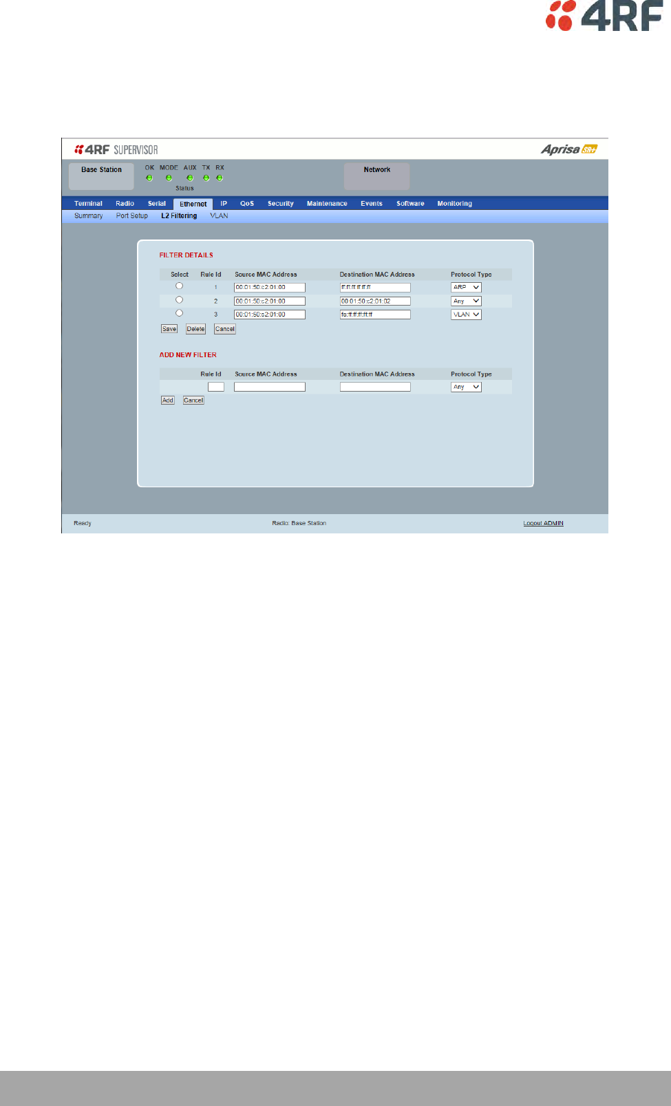
140 | Managing the Radio
Aprisa SR+ User Manual 1.6.0 PO
Ethernet > L2 Filtering
This page is only available if the Ethernet traffic option has been licensed (see ‘Maintenance > Licence’ on
page 216).
FILTER DETAILS
L2 Filtering provides the ability to filter (white list) radio link user traffic based on specified Layer 2 MAC
addresses.
User traffic originating from specified Source MAC Addresses destined for specified Destination MAC
Addresses that meets the protocol type criteria will be transmitted over the radio link.
User traffic that does not meet the filtering criteria will not be transmitted over the radio link.
Management traffic to the radio will never be blocked.
Source MAC Address
This parameter sets the filter to the Source MAC address of the packet in the format ‘hh:hh:hh:hh:hh:hh’.
If the Source MAC Address is set to ‘FF:FF:FF:FF:FF:FF’, traffic will be accepted from any source MAC
address.
Destination MAC Address
This parameter sets the filter to the Destination MAC address of the packet in the format
‘hh:hh:hh:hh:hh:hh’.
If the Destination MAC Address is set to ‘FF:FF:FF:FF:FF:FF’, traffic will be delivered to any destination
MAC address.
Managing the Radio | 141
Aprisa SR+ User Manual 1.6.0 PO
Protocol Type
This parameter sets the EtherType accepted ARP, VLAN, IPv4, IPv6 or Any type.
Example:
In the screen shot, the rules are configured in the base station which controls the Ethernet traffic to the
radio link.
Traffic from an external device with the Source MAC address 00:01:50:c2:01:00 is forwarded over the
radio link if it meets the criteria. All other traffic will be blocked.
Rule 1 If the Protocol Type is ARP going to any destination MAC address or
Rule 2 If the Protocol Type is Any and the destination MAC address is 01:00:50:c2:01:02 or
Rule 3 If the Protocol Type is VLAN tagged packets going to any unicast destination MAC address.
Special L2 Filtering Rules:
Unicast Only Traffic
This L2 filtering allows for Unicast only traffic and drop broadcast and multicast traffic. This filtering is
achieved by adding the two rules:
Rule
Source
MAC Address
Destination
MAC Address
Protocol Type
Allow ARPS
FF:FF:FF:FF:FF:FF
FF:FF:FF:FF:FF:FF
ARP
Allow Unicasts from Any source
FF:FF:FF:FF:FF:FF
FE:FF:FF:FF:FF:FF
Any
To delete a L2 Filter:
1. Click on an existing rule ‘Select’.
2. Click on Delete.
3. Click on OK.
ADD NEW FILTER
To add a L2 Filter:
1. Enter the Rule ID number. This is a unique rule number between 1 and 25.
2. Enter the Source MAC address of the packet or ‘FF:FF:FF:FF:FF:FF’ to accept traffic from any MAC
address.
3. Enter the Destination MAC address of the packet or ‘FF:FF:FF:FF:FF:FF’ to deliver traffic to any MAC
address.
4. Select the Protocol Type to ARP, VLAN, IPv4, IPv6 or Any type.
5. Click on Add.
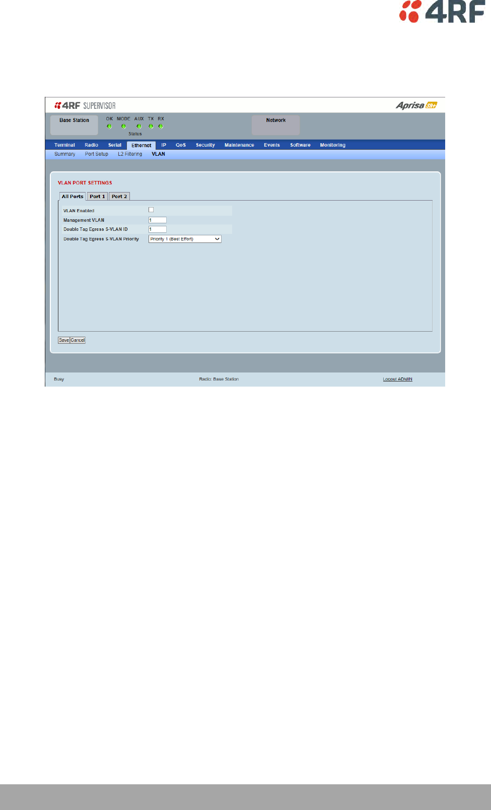
142 | Managing the Radio
Aprisa SR+ User Manual 1.6.0 PO
Ethernet > VLAN
This page is only available if the Ethernet traffic option has been licensed (see ‘Maintenance > Licence’ on
page 216).
VLAN PORT SETTINGS – All Ports
This page specifies the parameters that relate to all Ethernet ports when working in Bridge Mode. Three
parameters are global parameters for the Ethernet Bridge; enable / disable VLANs, Management VLAN ID
and the Double VLAN ID(S-VLAN) and the priority bit. These parameters can't be defined per port and are
globally defined for the Ethernet Bridge.
VLAN Enabled
This parameter sets if VLAN operation is required on the network. If it is enabled on the base station, it
must also be enabled on the remote / repeater stations. The default is disabled.
Management VLAN
This parameter sets the VLAN ID for management traffic only. The value can be between 1 and 4094. The
default is 1.
Double Tag Egress S-VLAN ID
This parameter sets the S-VLAN ID (outer tag) in the egress direction. The value can be between 1 and
4094. The default is 1.

Managing the Radio | 143
Aprisa SR+ User Manual 1.6.0 PO
Double Tag Egress S-VLAN Priority
This parameter sets the S-VLAN egress traffic priority. The default is Priority 1 (Best Effort).
Option
Egress Priority
Classification
High / Low
Priority
Priority 0 Background
0
Lowest Priority
Priority 1 (Best Effort)
1
Priority 2 (Excellent Effort)
2
Priority 3 (Critical Applications)
3
Priority 4 (Video)
4
Priority 5 (Voice)
5
Priority 6 (Internetwork Control)
6
Priority 7 (Network Control)
7
Highest Priority
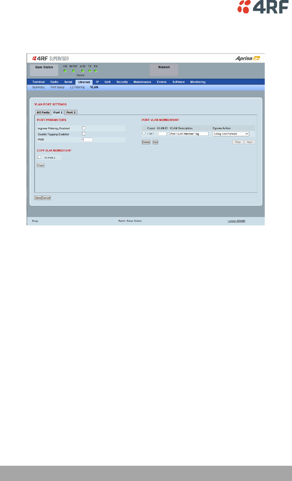
144 | Managing the Radio
Aprisa SR+ User Manual 1.6.0 PO
VLAN PORT SETTINGS – Port 1
This example is shown for the product option of 2E2S i.e. two Ethernet ports.
PORT PARAMETERS
Ingress Filtering Enabled
This parameter enables ingress filtering. When enabled, if ingress VLAN ID is not included in its member
set (inner tagged), the frame will be discarded.
If the Ingress Filtering is disabled, the Aprisa SR+ supports ‘Admit All Frames’ so that all frames tagged,
untagged and priority-tagged-frames are allowed to pass through the Ethernet ports. The default is
disabled.
Double Tagging Enabled
This parameter enables double tagging on this specific port. When enabled, if the ingress traffic is double
tagged, the Aprisa SR+ will check and validate that the S-VLAN ID matches the S-VLAN defined in 'Double
Tag Egress S-VLAN ID' in the 'all ports' tab. If there is a match, the packet will be forwarded into the
Bridge and the S-VLAN outer tag will be removed, thus the radio network will only forward a single VLAN.
If there isn’t a matching S-VLAN, the packet will be discarded. On egress, the outer tag (S-VLAN) is
appended with the 'Double Tag Egress S-VLAN ID' defined in the 'all ports' tab (see page 142). The default
is disabled.

Managing the Radio | 145
Aprisa SR+ User Manual 1.6.0 PO
If double tagging is enabled on the port, incoming frames should always be double tagged.
If the incoming frame is untagged, then the PVID (port VLAN ID) is used and forwarded with the Port
Ingress priority provided the PVID is configured in the Port VLAN Membership of any of the Ethernet
ports. If not, the frames are dropped.
If the incoming frame is single tagged, then PVID is used and forwarded with the Port Ingress priority
provided the PVID is configured in the Port VLAN Membership of any of the Ethernet ports. If not the
frames are dropped.
If double tagging is disabled on the port, incoming frames should always be single tagged, untagged or
priority–tagged frames.
Double tagged frames are simply forwarded treating them as if they were single tagged frames. At the
egress of the Ethernet port, such frames are forwarded only if the S-VLAN ID of that frame is a member of
the Port VLAN Membership.
PVID (Port VLAN ID)
This parameter sets the frame VLAN ID when the ingress frame is untagged (e.g. when in 'port VLAN
membership' the 'egress action' is set to 'untagged and forward') or priority-tagged (VLAN=0). The value
can be between 1 and 4094. The default is 1.
Note: The Port VLAN Membership must contain the PVID. If the Port VLAN Membership does not contain
the PVID, untagged or priority-tagged frames will be discarded.
COPY VLAN MEMBERSHIP
To Port
This parameter when set copies the port VLAN Membership settings to the other ports.
PORT VLAN MEMBERSHIP
VLAN ID
This parameter sets the VLAN ID of the port for a maximum 64 active VLANs. The value can be between 1
and 4094. The default is 1.
VLAN Description
This parameter is a freeform field used to identify the VLAN. It can be up to a maximum of 32 characters.

146 | Managing the Radio
Aprisa SR+ User Manual 1.6.0 PO
Egress Action
This parameter sets the action taken on the frame on egress from the Ethernet port. The default is Untag
and forward.
Option
Function
Untag and forward
Removes the tagged information and forwards the
frame. On Ingress, the VLAN tag will be added to the
PVID tag.
Forward
Forwards the tagged frame as it is on egress.
On Ingress, traffic is expected to include the VLAN tag
with a member VLAN ID, otherwise the packet will be
dropped.
Controls
The Add button adds the selected entry.
The Delete button deletes the selected entry.
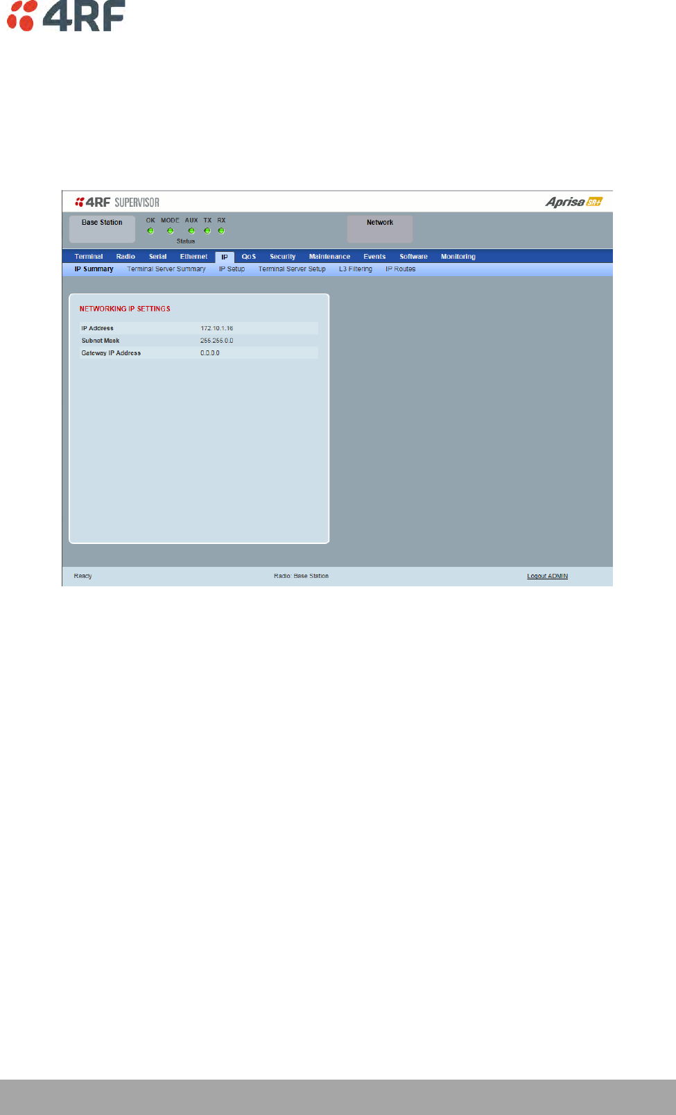
Managing the Radio | 147
Aprisa SR+ User Manual 1.6.0 PO
IP
IP > IP Summary > Bridge / Gateway Router Modes
This page displays the current settings for the Networking IP Settings for an Ethernet Operating Mode of
‘Bridge’ or ‘Gateway Router’.
See ‘IP > IP Setup > Bridge / Gateway Router Modes’ on page 150 for configuration options.
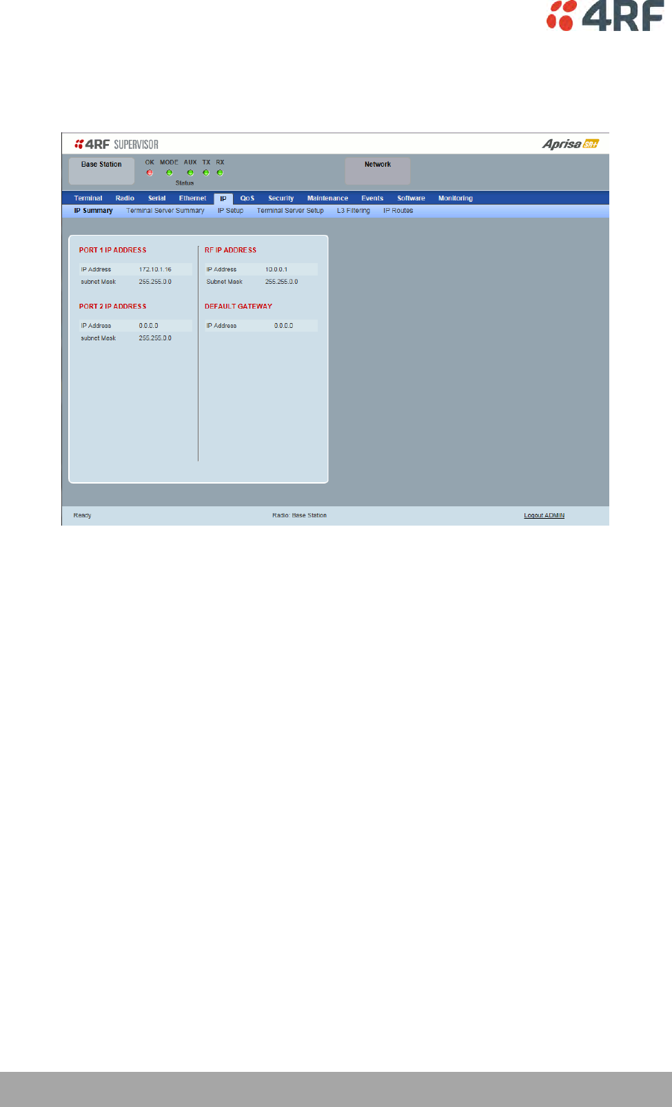
148 | Managing the Radio
Aprisa SR+ User Manual 1.6.0 PO
IP > IP Summary > Router Mode
This page displays the current settings for the Networking IP Settings for an Ethernet Operating Mode of
‘Router’.
See ‘IP > IP Setup > Router Mode’ on page 151 for configuration options.
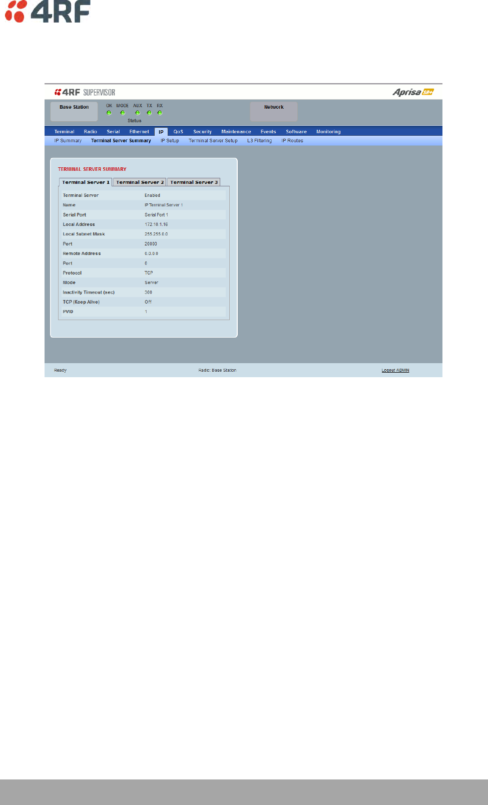
Managing the Radio | 149
Aprisa SR+ User Manual 1.6.0 PO
IP > IP Terminal Server Summary
This page displays the current IP Terminal Server settings.
TERMINAL SERVER SUMMARY
IP Terminal Server converts local incoming IP packets to a local physical serial port and to OTA serial
packets.
This function is typically used on a base / master station to convert traffic to serial OTA for transmission
to all remote radios
See ‘IP > IP Terminal Server Setup’ for configuration options.
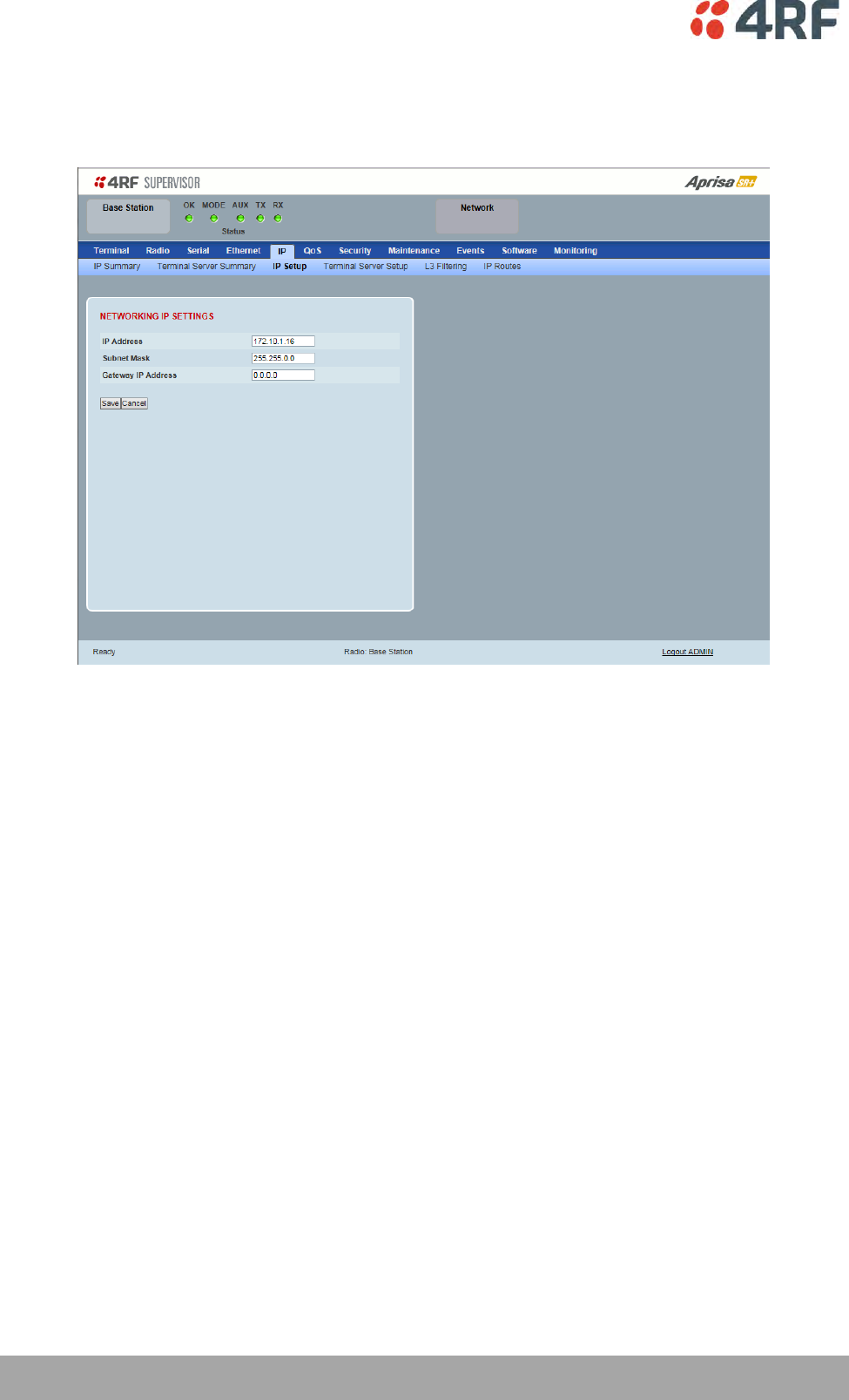
150 | Managing the Radio
Aprisa SR+ User Manual 1.6.0 PO
IP > IP Setup > Bridge / Gateway Router Modes
This page provides the setup for the IP Settings for an Ethernet Operating Mode of ‘Bridge’ or ‘Gateway
Router’.
NETWORKING IP SETTINGS
IP Address
Set the static IP Address of the radio (Management and Ethernet ports) assigned by your site network
administrator using the standard format xxx.xxx.xxx.xxx. This IP address is used both in Bridge mode and
in Router mode. The default IP address is in the range 169.254.50.10.
Subnet Mask
Set the Subnet Mask of the radio (Management and Ethernet ports) using the standard format
xxx.xxx.xxx.xxx. The default subnet mask is 255.255.0.0 (/16).
Gateway
Set the Gateway address of the radio, if required, using the standard format xxx.xxx.xxx.
A default gateway is the node on the network that traffic is directed to when an IP address does not
match any other routes in the routing table. It can be the IP address of the router or PC connected to the
base station. The default gateway commonly connects the internal radio network and the outside
network. The default Gateway is 0.0.0.0.
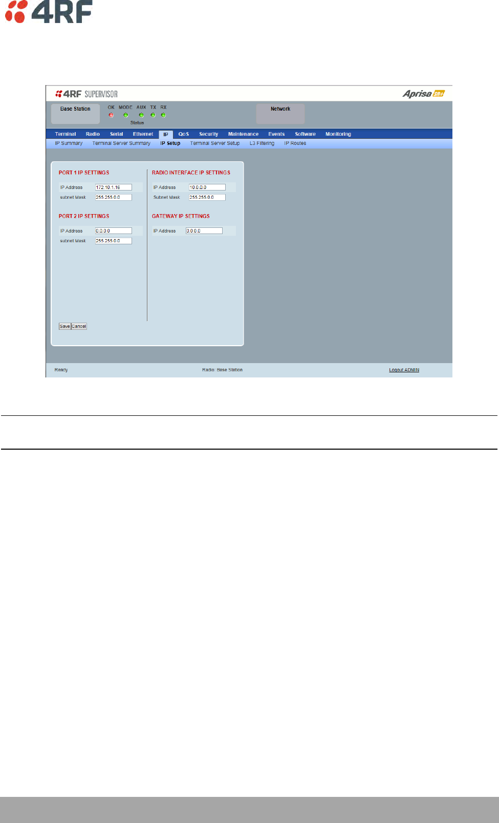
Managing the Radio | 151
Aprisa SR+ User Manual 1.6.0 PO
IP > IP Setup > Router Mode
This page provides the setup for the IP Settings for and Ethernet Operating Mode of ‘Router’.
PORT SETTINGS – port (n)
Note: This screen is dependent on the Data Port product option purchased (see ‘Data Interface Ports’ on
page 329). The Data Port product option shown is a 2E2S – two Ethernet ports and two Serial ports
IP Address
Set the static IP Address of the radio Ethernet port (n) assigned by your site network administrator using
the standard format xxx.xxx.xxx.xxx. This IP address is used for this Ethernet port Router mode.
Subnet Mask
Set the Subnet Mask of the of the radio Ethernet port (n) using the standard format xxx.xxx.xxx.xxx. The
default subnet mask is 255.255.0.0 (/16).
Gateway
Set the Gateway address of the radio Ethernet port (n), if required, using the standard format
xxx.xxx.xxx.
A default gateway is the node on the network that traffic is directed to when an IP address does not
match any other routes in the routing table. It can be the IP address of the router or PC connected to the
base station. The default gateway commonly connects the internal radio network and the outside
network. The default Gateway is 0.0.0.0.

152 | Managing the Radio
Aprisa SR+ User Manual 1.6.0 PO
RADIO INTERFACE IP SETTINGS
The RF interface IP address is the address that traffic is routed to for transport over the radio link. This IP
address is only used when Router Mode is selected i.e. not used in Bridge Mode.
Radio Interface IP Address
Set the IP Address of the RF interface using the standard format xxx.xxx.xxx.xxx. The default IP address is
in the range 10.0.0.0.
Radio Interface Subnet Mask
Set the Subnet Mask of the RF interface using the standard format xxx.xxx.xxx.xxx. The default subnet
mask is 255.255.0.0 (/16).
Note 1: If the base station RF interface IP address is a network IP address, and if the remote radio is also
using a network IP address within the same subnet or different subnet, then the base radio will assign an
automatic RF interface IP address from its own subnet.
When the base radio has a host specific RF interface IP address, then all the remotes must have a host
specific RF interface IP address from the same subnet.
Note 2: When a remote radio is configured for Router Mode and the base radio is changed from Bridge
Mode to Router Mode and the RF interface IP address is set to AUTO IP configuration (at least the last
octet of the RF interface IP address is zero), it is mandatory to configure the network topology by using
the ‘Decommission Node’ and ‘Discover Nodes’ (see ‘Maintenance > Advanced’ on page 217).
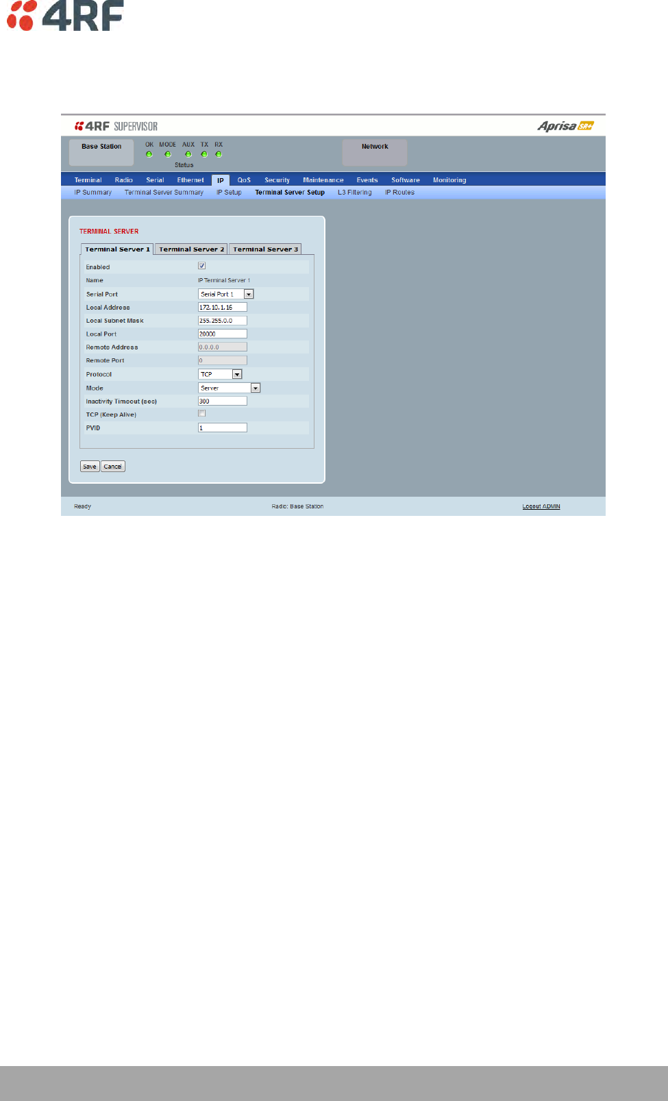
Managing the Radio | 153
Aprisa SR+ User Manual 1.6.0 PO
IP > IP Terminal Server Setup
This page provides the setup for the IP Terminal Server settings.
TERMINAL SERVER
Enabled
This parameter enables IP terminal server.
IP Terminal Server converts local incoming IP packets to a local physical serial port and to OTA serial
packets as well. This function is typically used on a base / master station to convert traffic to serial OTA
for transmission to all remote radios.
The serial terminal server traffic can be prioritized separately. For QoS, the priority of the serial terminal
server traffic is that of the configured priority for its associated serial port (see ‘QoS > Traffic Priority’ on
page 161).
Name
This parameter displays the IP terminal server port name.

154 | Managing the Radio
Aprisa SR+ User Manual 1.6.0 PO
Serial Port
This parameter selects the serial port to use IP terminal server.
Option
Function
Serial Port
This is the normal RS-232 serial ports provided with the RJ45
connector.
USB Serial Port
This is the optional RS-232 / RS-485 serial port provided with the
USB host port connector with a USB to RS-232 / RS-485 RJ45
converter cable (see ‘USB RS-232 / RS-485 Serial Port’ on page
353).
Local Address
This parameter sets the Terminal Server local IP address.
Bridge Mode
The local IP address can be the same as the radio's configured IP address or the Virtual IP address for
protected stations. If it is not the above, then it must be an IP address from a network different from the
radio's network.
Note that the Terminal Server local IP address settings can be the same for other terminal servers in the
radio.
Router Mode
The local IP address must be the same as any one of the radio's configured port IP addresses or the Virtual
IP address for protected stations.
Gateway Router Mode
The local IP address must be the same as the radio's configured IP address or the Virtual IP address for
protected stations.
Local Port
This parameter sets the TCP or UDP port number of the local serial port.
The valid port number range is less than or equal to 49151 but with exclusions of 0, 5445, 6445, 9930 or
9931. The default setting is 20000.
The user is responsible for ensuring that there is no conflict on the network.
Remote Address
This parameter sets the IP address of the server connected to the radio Ethernet port. When the remote
address / port is configured as 0.0.0.0/0, each outgoing UDP packet will be sent to the source address of
the last received UDP packet.
Remote Port
This parameter sets the TCP or UDP port number of the server connected to the radio Ethernet port. The
default setting is 0.
Protocol
This parameter sets the L4 TCP / IP or UDP / IP protocol used for terminal server operation. The default
setting is TCP.

Managing the Radio | 155
Aprisa SR+ User Manual 1.6.0 PO
Mode
This parameter defines the mode of operation of the terminal server connection. The default setting is
Client and Server.
Option
Function
Client
The radio will attempt to establish a TCP connection with the
specified remote unit. Generally, this setting is for the base station
with an Ethernet connection to the SCADA master.
Server
The radio will listen for a TCP connection on the specified local
port. Generally, this setting is for the remote station with a serial
connection to the RTU.
Data received from any client shall be forwarded to the associated
serial port while data received from that serial port shall be
forwarded to every client with an open TCP connection.
If no existing TCP connections exist, all data received from the
associated serial port shall be discarded.
Client and Server
The radio will listen for a TCP connection on the specified local
port and if necessary, establish a TCP connection with the
specified remote unit. Generally, this setting is used for the
remote station but it should be used carefully as two connections
might be established with the base station.
Data received from any client shall be forwarded to the associated
serial port while data received from that serial port shall be
forwarded to every client with an open TCP connection.
Inactivity Timeout (seconds)
This specifies the duration (in seconds) to automatically terminate the connection with the remote TCP
server if no data has been received from either the remote TCP server or its associated serial port for the
duration of the configured inactivity time.
TCP Keep Alive
A TCP keep alive is a message sent by one device to another to check that the link between the two is
operating, or to prevent the link from being broken.
If the TCP keep alive is enabled, the radio will be notified if the TCP connection fails.
If the TCP keep alive is disabled, the radio relies on the Inactivity Timeout to detect a TCP connection
failure. The default setting is disabled.
Note: An active TCP keep alive will generate a small amount of extra network traffic.
PVID
This parameter sets the PVID (port VLAN ID) for each of the terminal servers on the radio.
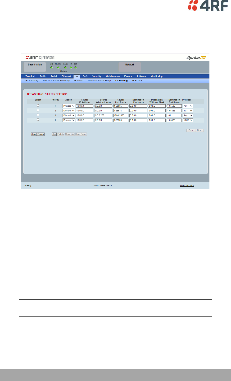
156 | Managing the Radio
Aprisa SR+ User Manual 1.6.0 PO
IP > L3 Filtering
This page is only available if the Ethernet traffic option has been licensed (see ‘Maintenance > Licence’ on
page 216). The filter operates in either Bridge Mode or Router Mode (see 'Terminal > Operating Mode’ on
page 94).
NETWORKING L3 FILTER SETTINGS
L3 Filtering provides the ability to evaluate traffic and take specific action based on the filter criteria.
This filtering can also be used for L4 TCP / UDP port filtering which in most cases relates to specific
applications as per IANA official and unofficial well-known ports.
Entering a * into any to field will automatically enter the wildcard values when the data is saved.
Priority
This parameter shows the priority order in which the filters are processed.
Action
This parameter defines the action taken on the packet when it meets the filter criteria.
Option
Function
Process
Processes the packet if it meets the filter criteria
Discard
Discards the packet if it meets the filter criteria
Source IP Address
If the source IP address is set to 0.0.0.0, any source IP address will meet the filter criteria.

Managing the Radio | 157
Aprisa SR+ User Manual 1.6.0 PO
Source Wildcard Mask
This parameter defines the mask applied to the source IP address. 0 means that it must be a match.
If the source wildcard mask is set to 0.0.0.0, the complete source IP address will be evaluated for the
filter criteria.
If the source wildcard mask is set to 0.0.255.255, the first 2 octets of the source IP address will be
evaluated for the filter criteria.
If the source wildcard mask is set to 255.255.255.255, none of the source IP address will be evaluated for
the filter criteria.
Note: The source wildcard mask operation is the inverse of subnet mask operation
Source Port Range
This parameter defines the port or port range for the source. To specify a range, insert a dash between
the ports e.g. 1000-2000. If the source port range is set to 1-65535, traffic from any source port will meet
the filter criteria.
Destination IP Address
This parameter defines the destination IP address of the filter. If the destination IP address is set to
0.0.0.0, any destination IP address will meet the filter criteria.
Destination Wildcard Mask
This parameter defines the mask applied to the destination IP address. 0 means that it must be a match.
If the destination wildcard mask is set to 0.0.0.0, the complete destination IP address will be evaluated
for the filter criteria.
If the destination wildcard mask is set to 0.0.255.255, the first 2 octets of the destination IP address will
be evaluated for the filter criteria.
If the destination wildcard mask is set to 255.255.255.255, none of the destination IP address will be
evaluated for the filter criteria.
Note: The destination wildcard mask operation is the inverse of subnet mask operation
Destination Port Range
This parameter defines the port or port range for the destination. To specify a range, insert a dash
between the ports e.g. 1000-2000. If the destination port range is set to 1-65535, traffic to any
destination port will meet the filter criteria.
Protocol
This parameter defines the Ethernet packet type that will meet the filter criteria.
Controls
The Delete button deletes the selected entry.
The Move Up button moves the selected entry above the entry above it increasing its process priority.
The Move Down button moves the selected entry below the entry above it reducing its process priority.
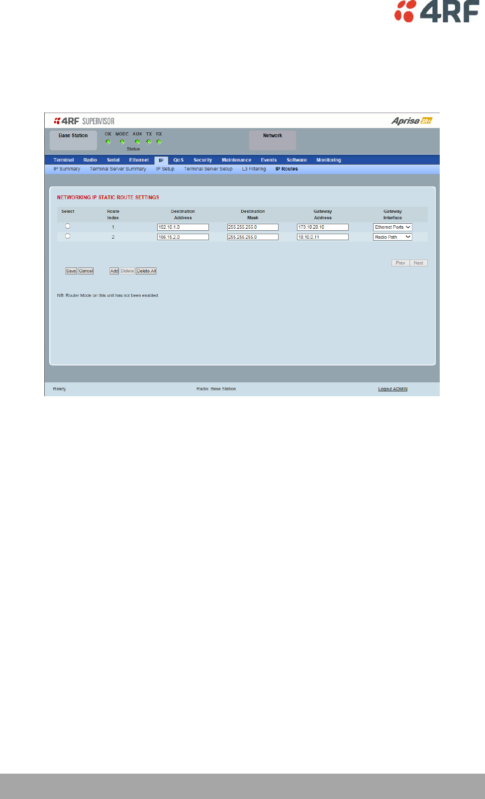
158 | Managing the Radio
Aprisa SR+ User Manual 1.6.0 PO
IP > IP Routes
This page is only available if the Ethernet traffic option has been licensed (see ‘Maintenance > Licence’ on
page 216) and Router Mode selected. It is not valid for Bridge Mode (see 'Terminal > Operating Mode’ on
page 94).
NETWORKING IP STATIC ROUTE SETTINGS
Static routing provides the ability to evaluate traffic to determine if packets are forwarded over the radio
link or discarded based on the route criteria.
Route Index
This parameter shows the route index.
Destination Address
This parameter defines the destination IP address of the route criteria.
Destination Mask
This parameter defines the subnet mask applied to the Destination IP Address. 255 means that it must be a
match.
If the destination subnet mask is set to 255.255.255.255, all octets of the Destination IP Address will be
evaluated for the route criteria.
If the destination subnet mask is set to 255.255. 0.0, the first 2 octets of the Destination IP Address will be
evaluated for the route criteria.

Managing the Radio | 159
Aprisa SR+ User Manual 1.6.0 PO
Gateway Address
This parameter sets the gateway address where packets will be forwarded to.
If the gateway interface is set to Ethernet Ports, the gateway address is the IP address of the
device connected to the Ethernet port.
If the gateway interface is set to Radio Path, the gateway address is the IP address of the remote
radio.
Gateway Interface
This parameter sets the destination interface.
Option
Function
Ethernet Ports
Packets are forwarded to the Ethernet interface port.
Radio Path
Packets are forwarded to the RF Interface radio path.