ABB Xiamen Smart Technology M2136 Mini video outdoor station User Manual Operating instruction
ABB Genway Xiamen Electrical Equipment Co., Ltd Mini video outdoor station Operating instruction
Contents
- 1. Operating instruction
- 2. Product manual
Operating instruction
English
Mini Video Outdoor Station
WARNING
Dangerous currents flow through the body when coming
into direct or indirect contact with live components.
This can result in electric shock, burns or even death.
Disconnect the mains power supply prior to
installation and/or disassembly!
Permit work on the 110-240 V supply system to be
performed only by specialist staff.
Please read the mounting instructions carefully and keep them
for future use.
Detailed user manual is available via the link in chapter "Service"
or by scanning the QR codes (device with corresponding software
is required).
Intended use
The outdoor station is part of the ABB-Welcome door communication
system and operates exclusively with components from this system.
Mini video outdoor station has 1/2 round pushbuttons, light switch or
calling guard programmable for the button, built-in ID card reader and
up to 2 locks connections.
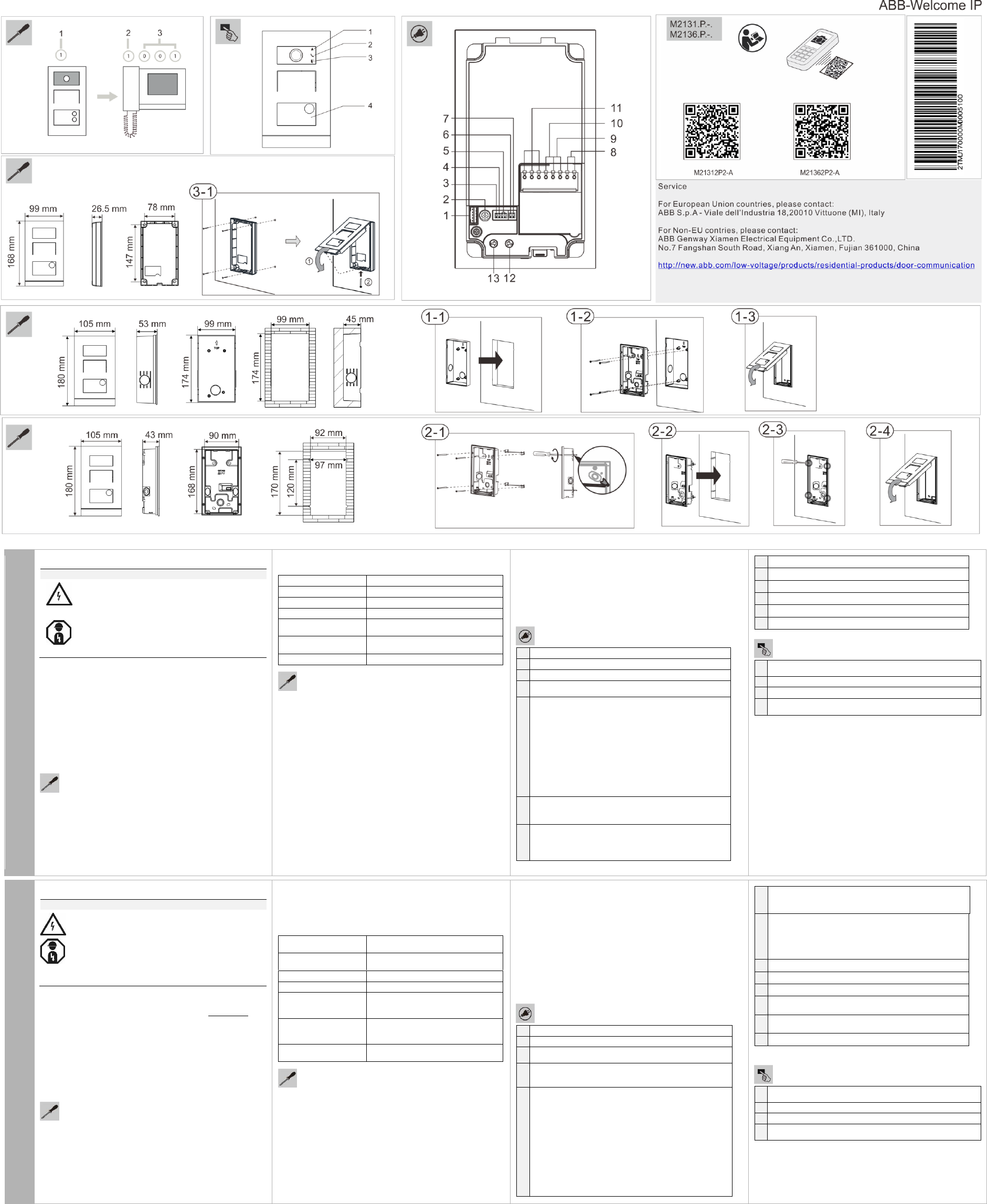
Addressing
For outdoor stations: With the selector switch 1 set the address of
the outdoor station (1 to 9).
For indoor stations: With the left selector switch 2 set the address
of the default outdoor station (1 to 9).
Then use the other two selector switches and dip-switches 3 to set
the address (hundreds, tens and units digits e.g. 001) of the indoor
station.
Technical data
Single-wire clamps
2 x 0.28 mm² - 2 x 0.75 mm²
Fine-wire clamps
2 x 0.28 mm² - 2 x 0.75 mm²
Bus voltage
20-30 V DC
Protection
IP 54
Power supply ,door
opener (Lock-GND)
18 V 4 A impulsive, 250 mA holding
Floating output, door
opener (COM-NC-NO)
30 V AC/DC 1 A
Operating temperature
-40 °C - +70 °C -40 °F - +158 °F
Installation
Flush mounting with pre-installation box
1-1. Cut a square groove in the wall and put the pre-installation
box into it.
1-2. Put the lower cover of the outdoor station into the groove and
fix it with screws.
1-3. Do the wiring and close the outdoor station.
Cavitiy wall installation
2-1. Mount the screws and clips onto the outdoor station.
2-2. Fix it onto the wall; screw, install and tighten the screws.
2-3. Do the wiring and close the outdoor station.
Surface mounting
3-1. Fix the lower cover of the outdoor station onto the wall with
screws, do the wiring and close the outdoor station.
3-2. Fix the lower cover of the outdoor station onto the 86 box with
screws, do the wiring and close the outdoor station.
Precautions for installation
When opening a square groove for the lower cover of the equipment,
you must control the embedded depth, ensuring the outer edge of the
lower cover can be fully attached to the wall, but should not leave a
large gap between the exposed parts of the face shell and the wall
after the installation of the equipment;
Do not install in raining, humid or dusty environments, and not near
objects of high temperature or strong corrosion.
Terminal description
1
Connector for device software update
2
Rotary switch to set the address of OS (1-9)
3
Set feedback tone of pushbutton: ON/OFF
4
Set general call to all indoor stations in one family: ON/OFF
If GC=ON, press button 1/button 2, all IS ring
5
Configuration function of 1st/2nd round pushbutton
5A Mini Video Outdoor Station with one pushbutton
3 -> OFF; 4 -> OFF = Call IS 001
3 -> ON; 4 -> OFF = Switch on light
3 -> OFF; 4 -> ON = Call guard unit
3 -> ON; 4 -> ON = Call IS 001
5B Mini Video Outdoor Station with two pushbuttons
3 -> OFF; 4 -> OFF = Call IS 001/002
3 -> ON; 4 -> OFF = Switch on light/call IS 001
3 -> OFF; 4 -> ON = Call guard unit/call IS 001
3 -> ON; 4 -> ON = Call IS 001/call IS 002
6
Set the video mode PAL/NTSC
OFF = PAL video mode
ON = NTSC video mode
7
Set default lock
OFF = set (Lock-GND) as default lock
ON = set (COM-NC-NO) as default lock
*Default lock is controlled by "unlock" button on IS
8
Plug-in clamps (a,b) for bus connection
9
Plug-in clamps (Exit-GND) for exit button
10
Plug-in clamps (Lock-GND) for door opener
11
Plug-in clamps (COM-NC-NO) for floating output, door opener
12
Rotary switch to adjust default door lock release time, 1-10s
13
Rotary switch to adjust loudspeaker volume
Operation
1
LED flashed slowly to indicate call established
LED flashed fast to indicate system busy
2
LED illuminate to indicate communication possible
3
LED illuminate to indicate door unlocked
4
If round pushbutton with ID card reader,please find the details in
outdoor station manual.
FCC ID: 2AEBL-M2131
FCC ID: 2AEBL-M2136
These devices comply with Part 15 of the FCC Rules Operation is
subject to the following two conditions: (1) These devices may not
cause harmful interference, and (2) These devices must accept any
interference received, including interference that may cause unde-
sired operation. Changes or modifications not expressly approved by
the party responsible for compliance could void the user's authority to
operate the equipment.
These devices comply with radiation exposure limits set forth for an
uncontrolled environment. In order to avoid the possibility of exceed-
ing the FCC radio frequency exposure limits, human proximity to the
antenna shall not be less than 20cm (8 inches) during normal opera-
tion.
Español
Estación al Aire Libre de Mini Video
ADVERTENCIA
En caso de entrar en contacto, directa o indirectamente,
con componentes por los que circule una corriente
eléctrica, se puede sufrir una descarga eléctrica peligrosa,
cuyo resultado puede ser choque eléctrico, quemaduras
o, incluso, la muerte.
¡Desconecte la tensión de red antes de proceder al
montaje o desmontaje!
Encargue los trabajos en la red eléctrica de 110-240 V
solo al personal técnico competente.
Por favor, lea las instrucciones de montaje y guárdelas para ser
usadas en el futuro.
El manual de usuario puede ser descargado en www.abb.es.
Uso indicado
La estación al aire libre es parte del sistema de interfonía de ABB-
Welcome y funcionamiento exclusivo con componentes de este sis-
tema
Mini estación al aire libre de vídeo tiene 1/2 pulsadores redondos, in-
terruptor de iluminación o bloqueo de llamada programable para el
botón, una función de lector de tarjeta de identificación y hasta 2 co-
nexiones cerraduras.
Direccionamiento
Para las estaciones al aire libre: Con el selector 1 se establece la
dirección de la estación al aire libre (1 a 9).
Para las estaciones de interior: Con el interruptor de selección iz-
quierdo 2 se establece la dirección de la estación al aire libre prede-
terminada (1 a 9).
A continuación, utilice los otros dos interruptores 3 para establecer la
dirección (cientos, decenas y dígitos de unidades por ejemplo, 001)
de la estación interior.
Datos Técnicos
Abrazaderas de un
solo alambre
2 x 0.28 mm² - 2 x 0.75 mm²
Abrazaderas alambre
fino
2 x 0.28 mm² - 2 x 0.75 mm²
Tensión de bus
20-30 V DC
Protección
IP 54
Fuente de alimenta-
ción, apertura de
puerta (Lock-GND)
Impulsivo 18 V 4 A, Retención 250
mA
Salida flotante,
apertura de puerta
(COM-NC-NA)
30 V CA/CD 1 A
Temperatura de fun-
cionamiento
-40 °C - +70 °C -40 °F - +158 °F
Montaje en una actual estación exterior y conexión
Instalación empotrada (con caja empotrada)
1-1. Corte una ranura cuadrada en la pared y coloque la caja
empotrada en ella.
1-2. Coloque la tapa inferior de la estación para exteriores en la
ranura y fíjela con tornillos.
1-3. Realice el cableado y cierre la estación para exteriores
Instalación empotrada (pared hueca)
2-1. Instale los tornillos y abrazaderas en la estación para
exteriores.
2-2. Fíjela a la pared; atornille, instale y apriete los tornillos.
2-3. Realice el cableado y cierre la estación para exteriores.
Instalación en superficie
3-1 Fije la tapa inferior de la estación para exteriores a la pared
con tornillos, realice el cableado y cierre dicha estación.
Precautions for installation
When opening a square groove for the lower cover of the equipment,
you must control the embedded depth, ensuring the outer edge of the
lower cover can be fully attached to the wall, but should not leave a
large gap between the exposed parts of the face shell and the wall
after the installation of the equipment;
Do not install in raining, humid or dusty environments, and not near
objects of high temperature or strong corrosion.
Montaje y Conexión
1
Conector para la actualización del software del dispositivo
2
Interruptor giratorio para ajustar la dirección del OS (1-9)
3
Ajustar el tono de retroalimentación del botón de pulsado:
ON/OFF
4
Ajustar la llamada general a toda la estación interior en un solo
grupo: ON/OFF
Si GC=ON, pulse el botón 1/botón 2, todo timbre IS
5
La función de configuración del primer/segundo botón de pul-
sado redondo
5A Estación al aire libre de Mini Video con un botón de pulsado
3 -> OFF; 4 -> OFF = Llamada IS 001
3 -> ON; 4 -> OFF = Encender la luz
3 -> OFF; 4 -> ON = Unidad de bloqueo de llamada
3 -> ON; 4 -> ON = Llamada IS 001
5B Mini Video Estación al aire libre con dos botones pulsado
3 -> OFF; 4 -> OFF = llamada IS 001/002
3 -> ON; 4 -> OFF = Encender luz/llamada IS 001
3 -> OFF; 4 -> ON = Boqueo de llamadas unidad/llamada IS 001
3 -> ON; 4 -> ON = Llamada IS 001/llamada IS 002
6
Ajustar el modo de video PAL/NTSC
OFF = Modo video PAL
ON = Modo video NTSC
7
Definir bloqueio padrão
OFF = definir (Lock-GND) como bloqueio padrão
ON = definir (COM-NC-NO) como bloqueio padrão
* O bloqueio padrão é controlado pelo botão "unlock"
(desbloquear) no IS
8
Braçadeiras plug-in (a, b) para ligação bus
9
Braçadeiras plug-in (Exit-GND) para botão de saída
10
Braçadeiras plug-in (Lock-GND) para abridor de porta
11
Braçadeiras plug-in (COM-NC-NO) para saída flutuante e
abridor de porta
12
Interruptor rotativo para ajustar tempo de libertação de bloqueio
de porta padrão, 1-10 seg
13
Interruptor rotativo para ajustar volume de coluna
Funcionamiento
1
LED a piscar devagar indica chamada estabelecida
LED a piscar rápido indica sistema ocupado
2
LED ligado indica comunicação possível
3
LED ligado indica porta desbloqueada
4
Se o botão redondo tiver leitor de cartão ID, consulte os detalhes no
manual da estação exterior.
Italiano
Mini Stazione Video per Esterni
AVVERTIMENTO
Il contatto diretto o indiretto con parti attraversate da
corrente elettrica provoca pericolosi flussi di corrente
attraverso il corpo.
Le conseguenze possono essere folgorazione, ustioni o
morte.
Prima del montaggio o dello smontaggio scollegare la
tensione di rete!
Affidare gli interventi sulla rete elettrica a 110-240 V
esclusivamente a personale specializzato.
Si prega di leggere le istruzioni di montaggio con attenzione e
conservarle per future consultazioni.
Il manuale utente dettagliato è disponibile sul sito nel capitolo
“Service" o utilizzando il QR code (necessario software per la
lettura)
Uso conforme alle prescrizioni
La stazione in esterni è parte del sistema di porta di comunicazione
ABB-Welcome e funziona esclusivamente con componenti di tale
sistema.
La Mini stazione video per esterni ha 1/2 pulsanti rotondi, interruttore
di luce o chiamata di guardia programmabile per il tasto, lettore ID
card incorporato e fino a 2 blocchi di connessione.
Programmazione
Per stazioni in esterni: con il selettore 1 impostare l’indirizzo della
stazione in esterni (da 1 a 9).
Per stazioni in interni: con il selettore 2 di sinistra impostare
l’indirizzo della stazione in esterni di default (da 1 a 9).
Usare gli altri due selettori e interruttori 3 per impostare l’indirizzo
(centinaia, decine e unità, ad es. 001) della stazione in interni.
Dati Tecnici
Morsetti di cavo singolo
2 x 0.28 mm² - 2 x 0.75 mm²
Morsetti di cavo fine
2 x 0.28 mm² - 2 x 0.75 mm²
Tensione Bus
20-30 V CC
Protezione
IP 54
Alimentazione, apertura
porta (Lock-GND)
18 V 4 A impulso, 250 mA tenuta
Output mobile, apertura
porta (COM-NC-NO)
30 V AC/CC 1 A
Temperatura di esercizio
-40 °C - +70 °C -40 °F - +158 °F
Montaggio in preesistente stazione esterna
e Connessione
Installazione a parete (con scatola a muro)
1-1. Creare una cavità quadrata nella parete ed inserirvi la scatola.
1-2. Mettere il coperchio inferiore della stazione esterna nella
cavità e fissarlo con le viti.
1-3. Eseguire il cablaggio e chiudere la stazione esterna.
Installazione a parete (intercapedine)
2-1. Mettere le viti ed I fermagli sulla stazione esterna.
2-2. Fissarla alla parete, installare e stringere le viti.
2-3. Eseguire il cablaggio e chiudere la stazione esterna.
Installazione su superficie
3-1 Fissare il coperchio inferiore della stazione esterna al muro
utilizzando le viti, eseguire il cablaggio e chiudere la stazione
esterna.
Precauzioni per l'installazione
Quando si esegue la cavità quadrata per la copertura inferiore
dell'apparecchiatura, è necessario controllare la profondità,
assicurandosi che il bordo esterno del coperchio inferiore possa
essere attaccato completamente al muro, senza lasciare spazi tra le
parti esposte della facciata e la parete dopo l'installazione
dell'apparecchiatura.
Non installare in ambienti soggetti a pioggia, umidità o polvere; e non
installare vicino a oggetti ad alta temperatura o a forte corrosione.
Montaggio & Connessione
1
Connettore per aggiornamento software dispositivo
2
Interrutore a rotazione per impostare l’indirizzo di OS (1-9)
3
Imposta tono di risposta di pressione pulsante: ON/OFF
4
Imposta chiamata generale per tutte le stazioni in interni in una
sola famiglia: ON/OFF
Se GC=ON, premere il tasto 1/tasto 2, tutti gli IS suonano
5
Funzione di configurazione di 1°/2° pulsante rotondo
5A Mini Video Stazione per Esterni con un solo pulsante
3 -> OFF; 4 -> OFF = Chiama IS 001
3 -> ON; 4 -> OFF = Accende la luce
3 -> OFF; 4 -> ON = Chiama unità di guardia
3 -> ON; 4 -> ON = Chiama IS 001
5B Mini Video Stazione per Esterni con due pulsanti
3 -> OFF; 4 -> OFF = Chiama IS 001/002
3 -> ON; 4 -> OFF = Accende la luce / Chiama IS 001
3 -> OFF; 4 -> ON = Chiama unità di guardia / Chiama IS 001
3 -> ON; 4 -> ON = Chiama IS 001/ Chiama IS 002
6
Imposta la modalità video PAL/NTSC
OFF = modalità video PAL
ON = modalità video NTSC
7
Imposta blocco di default
OFF = imposta (Lock-GND) come blocco di default
ON = imposta (COM-NC-NO) come blocco di default
* Il blocco di default è controllato dal tasto "sblocca" su IS
8
Innesta i morsetti di (a,b) per connessione del bus
9
Innesta i morsetti (Exit-GND) per il tasto di uscita
10
Innesta i morsetti (Lock-GND) per l’apertura della porta
11
Innesta i morsetti (COM-NC-NO) per uscita mobile, apertura
porta
12
Interrutore a rotazione per regolare il tempo di rilascio del blocco
porta di default, 1-10s
13
Interrutore a rotazione per regolare il volume dell’altoparlante
Funzionamento
1
LED lampeggia lentamente per indicare chiamata stabilita
LED lampeggia veloce per indicare che il sistema è occupato
2
LED si accende per indicare comunicazione possibile
3
LED si accende per indicare porta sbloccata
4
Se il pulsante è rotondo con lettore ID card,consultare i dettagli nel
manuale della stazione in esterni.
Français
Poste extérieur vidéo mini
AVERTISSEMENT
Un contact direct ou indirect avec des pièces sous tension
entraîne un passage de courant dangereux dans le corps.
Celui-ci risque d’entraîner un choc électrique, des brûlures
ou la mort.
Déconnectez la tension secteur avant tout montage
et démontage !
Faites réaliser toute intervention sur l'alimentation
électrique en 110-240 V uniquement par un
personnel spécialisé !
Lisez attentivement les instructions de montage et gardez les
pour une utilisation future.
Une notice d'utilisation est disponible via le lien dans le chapitre
"Service" ou en scannant le QR code (avec un appareil équipé
d'un logiciel adapté).
Utilisation prévue
Le poste extérieur fait partie du système de communication de porte
ABB-Welcome et fonctionne exclusivement avec les composants de
ce système.
Le poste extérieur vidéo mini a 1/2 boutons poussoirs ronds, un inter-
rupteur de lumière ou protection d'appel programmable pour le bouton,
un lecteur de carte d'identité intégré et jusqu'à 2 connexions de ver-
rouillage.
Adressage
Pour les postes extérieurs: Avec le commutateur de sélection 1
définir l'adresse du poste extérieur (1 à 9).
Pour les postes intérieurs: Avec le commutateur de sélection
gauche 2 définir l'adresse du poste extérieure par défaut (1 à 9).
Ensuite, utiliser les deux autres commutateurs de sélection et les
commutateurs DIP 3 pour définir l'adresse (des chiffres des cen-
taines, des dizaines et des unités par exemple 001) du poste inté-
rieur.
Données techniques
Colliers de serrage à fil
unique
2 x 0.28 mm² - 2 x 0.75 mm²
Colliers de serrage à fil
fin
2 x 0.28 mm² - 2 x 0.75 mm²
Tension du bus
20-30 V CC
Protection
IP 54
Alimentation, Ouvre-
porte (Lock-GND)
18 V 4 A impulsive, 250 mA détenue
Sortie flottante, Ouvre-
porte (COM-NC-NO)
30V CA/CC 1 A
Température de fonc-
tionnement
-40 °C - +70 °C -40 °F - +158 °F
Montage dans une station extérieure existante et
Connexion
Montage mural (avec boîtier mural)
1-1. Découpez une encoche carrée dans le mur et mettez-y le
boîtier mural.
1-2. Mettez le couvercle inférieur de la station extérieure dans
l'encoche et fixez-le avec des vis.
1-3. Effectuez le câblage et fermez la station extérieure.
Montage mural (mur avec cavité)
2-1. Montez les vis et les clips sur la station extérieure.
2-2. Fixez-la sur le mur ; vissez, installez et serrez les vis.
2-3. Effectuez le câblage et fermez la station extérieure.
Montage en surface
3-1 Fixez le couvercle inférieur de la station extérieure sur le mur
avec des vis, effectuez le câblage et fermez la station
extérieure.
Précautions pour l'installation
En ouvrant une encoche carrée pour le couvercle inférieur de
l'équipement, vous devez contrôler la profondeur encastrée, en vous
assurant que le bord extérieur du couvercle inférieur peut être
complètement fixé au mur, mais ne doit pas laisser un écart
important entre les parties exposées de la coque de face et le mur
après l'installation de l'équipement ;
Ne pas installer dans des environnements pluvieux, humides ou
poussiéreux, ni à proximité d'objets à haute température ou
présentant une forte corrosion.
Montage et Connexion
1
Connecteur pour la mise à jour du logiciel de l'appareil
2
Commutateur rotatif pour définir l'adresse de l'OS (1-9)
3
Définir le ton de la rétroaction du bouton-poussoir: ON / OFF
4
Définir l'appel général à tous les postes intérieurs dans une fa-
mille: ON / OFF
Si GC = ON, appuyer sur le bouton 1/bouton 2 , tout EST an-
neau
5
Fonction de configuration du 1er / 2ème bouton-poussoir rond
Poste extérieur vidéo mini 5A avec un bouton poussoir
3 -> OFF; 4 -> OFF = Appel IS 001
3 -> ON; 4 -> OFF = Allumer la lumière
3 -> OFF; 4 -> ON = Unité de protection d'appel
3 -> ON; 4 -> ON = Appel IS 001
Poste extérieur vidéo mini 5B avec deux boutons poussoirs
3 -> OFF; 4 -> OFF = Appel IS 001/002
3 -> ON; 4 -> OFF = Allumer la lumière/appel IS 001
3 -> OFF; 4 -> ON = Unité de protection d'appel / appel IS 001
3 -> ON; 4 -> ON = Appel IS 001 / appel IS 002
6
Régler le mode vidéo PAL / NTSC
OFF = Mode vidéo PAL
ON = Mode vidéo NTSC
7
Définir le verrouillage par défaut
OFF = définir (Lock-GND) en tant que verrouillage par défaut
ON = définir (COM-NC-NO) en tant que verrouillage par défaut
* Verrouillage par défaut est contrôlé par le bouton "déverrouil-
lage" sur IS
8
Pinces de connexion (a, b) pour la connexion de bus
9
Pinces de connexion (Exit-GND) pour le bouton de sortie
10
Pinces de connexion (Lock-GND) pour ouvre-porte
11
Pinces de connexion (COM-NC-NO) pour sortie flottante, ouvre-
porte
12
Commutateur rotatif pour régler le temps de relâchement du
verrouillage de la porte par défaut, 1-10s
13
Commutateur rotatif pour régler le volume du haut-parleur
Fonctionnement
1
Le voyant LED a clignoté lentement pour indiquer l'appel établi
Le voyant LED a rapidement clignoté pour indiquer un système oc-
cupé
2
Le voyant LED s'allume pour indiquer une communication possible
3
Le voyant LED s'allume pour indiquer une porte déverrouillée
4
Si le bouton-poussoir rond avec lecteur de carte d'identité,veuillez
trouver les détails dans le manuel du poste extérieur.
Polski
Stacja zewnętrzna mini wideo
OSTRZEŻENIE
Bezpośredni lub pośredni kontakt z częściami pod
napięciem prowadzi do niebezpiecznego przepływu prądu
elektrycznego przez organizm. Może to spowodować
porażenie prądem, poparzenia lub śmierć.
Przed montażem i demontażem należy odłączyć
napięcie sieciowe!
Prace przy sieci 110-240 V mogą wykonywać
wyłącznie specjaliści!
Prosimy dokładnie przeczytać instrukcję montażu oraz
przechować ją na przyszłość.
Szczegółowy podręcznik użytkownika można znaleźć za pomocą
linku w rozdziale „Obsługa” lub skanując kody QR (niezbędne jest
urządzenie z odpowiednim oprogramowaniem).
Użytkowanie zgodne z przeznaczeniem
Stacja zewnętrzna jest częścią systemu komunikacji domofonowej
ABB-Welcome i współdziała wyłącznie z elementami tego systemu.
Stacje zewnętrzne mini wideo posiadają okrągłe przyciski ½, włącznik
światła lub wzywanie ochrony programowane dla przycisku,
wbudowany czytnik kart ID oraz połączenia do maksimum dwóch
zaczepów zamka.
Adresowanie
Dla stacji zewnętrznych: Na wybieraku 1 ustawić adres stacji
zewnętrznej (od 1 do 9).
Dla stacji wewnętrznych: Najpierw na wybieraku 2 po lewej stronie
ustawić adres domyślnej stacji zewnętrznej (od 1 do 9).
Następnie użyć pozostałych dwóch wybieraków i mini-przełączników
DIP 3 do ustawienia adresu (setki, dziesiątki i jednostki, np. 001) stacji
wewnętrznej.
Dane techniczne
Zaciski przewodów
jednożyłowych
2 x 0.28 mm² - 2 x 0,75 mm²
Zaciski przewodów
cienkożyłowych
2 x 0.28 mm² - 2 x 0,75 mm²
Napięcie szyny
20-30 V DC
Stopień ochrony
IP 54
Zasilanie, zaczep
zamka drzwi (Lock-
GND)
18 V 4 A impuls, 250 mA trzymanie
Wyjście zmienne,
zaczep zamka drzwi
(COM-NC-NO)
30V AC/DC 1 A
Temperatura robocza
-40 °C - +70 °C -40 °F - +158 °F
Montaż w istniejącej stacji zewnętrznej i
podłączenie
Montaż na ścianie (ze skrzynką do montażu na ścianie)
1-1. Wytnij w ścianie kwadratowy rowek i włóż do niego skrzynkę
montażu na ścianie.
1-2. Umieść w rowku dolną pokrywę stacji zewnętrznej i przymocuj
ją śrubami.
1-3. Podłącz okablowanie i zamknij stację zewnętrzną.
Montaż na ścianie (mur szczelinowy)
2-1. Przykręć śruby i zaczepy do stacji zewnętrznej.
2-2. Przymocuj ją do ściany; przykręć, zainstaluj i dokręć śrubami.
2-3. Podłącz okablowanie i zamknij stację zewnętrzną.
Montaż powierzchni
3-1 Zamocuj dolną pokrywę stacji zewnętrznej śrubami do ściany,
podłącz okablowanie i zamknij stację zewnętrzną.
Środki ostrożności podczas instalacji
Podczas otwierania kwadratowego rowka na dolną pokrywę
urządzenia, należy kontrolować głębokość wbudowania sprawdzając,
czy zewnętrzną krawędź dolnej pokrywy można całkowicie
przymocować do ściany, po instalacji urządzenia nie należy
pozostawiać dużego odstępu pomiędzy wystającymi częściami
przodu obudowy, a ścianą;
Nie należy instalować podczas deszczu w miejscach wilgotnych lub
zakurzonych, a także z dala od obiektów o wysokiej temperaturze lub
silnie skorodowanych.
Montaż i Połączenie
1
Przyłącze do aktualizacji oprogramowania urządzenia
2
Przełącznik obrotowy do ustawiania adresu stacji zewnętrznych
(1-9)
3
Przycisk ustawiania sygnału zwrotnego: ON/OFF
4
Ustawienie ogólnego dzwonka CG do wszystkich stacji
wewnętrznych dla jednej rodziny: ON/OFF
Jeśli CG=ON, to po naciśnięciu przycisku 1/2, dzwonią
wszystkie stacje wewnętrzne
5
Konfiguracja funkcji 1szego/2giego przycisku
5A stacja zewnętrzna mini wideo na jeden przycisk
3 -> OFF; 4 -> OFF = dzwoni stacja wew. 001
3 -> ON; 4 -> OFF = włączenie światła
3 -> OFF; 4 -> ON = wezwanie ochrony
3 -> ON; 4 -> ON = dzwoni stacja wew. 001
5B stacja zewnętrzna mini wideo na dwa przyciski
3 -> OFF; 4 -> OFF = dzwoni stacja wew. 001/002
3 -> ON; 4 -> OFF = włączenie światła/dzwoni stacja wew. 001
3 -> OFF; 4 -> ON = wezwanie ochrony/dzwoni stacja wew. 001
3 -> ON; 4 -> ON = dzwoni stacja wew. 001/002
6
Ustawienie trybu wideo PAL/NTSC
OFF = tryb wideo PAL
ON = tryb wideo NTSC
7
Ustawienie zamka domyślnego
OFF = (Lock-GND) jako zamek domyślny
ON = (COM-NC-NO) jako zamek domyślny
*Zamek domyślny jest sterowany przyciskiem otwierania "unlock"
na stacji wew.
8
Złącza wtykowe (a,b.) do połączeń do szyny
9
Złącza wtykowe (Exit-GND) do przycisku wyjścia
10
Złącza wtykowe (Lock-GND) do zaczepu zamka
11
Złącza wtykowe (COM-NC-NO) do zmiennego wyjścia, zaczepu
zamka
12
Przełącznik obrotowy do ustawiania domyślnego czasu
zwalniania zamka drzwi, 1-10s
13
Przełącznik obrotowy do ustawiania głośności głośnika
Działanie
1
LED migający wolno wskazuje na ustawienie dzwonka
LED migający szybko wskazuje na zajętość systemu
2
LED świecący się wskazuje na możliwość komunikacji
3
LED świecący się wskazuje na otwarty zamek drzwi
4
Odnośnie przycisku z czytnikiem kart ID, informacje znajdują się w
instrukcji obsługi stacji zewnętrznej.