ABIOMED 0042-4000 IMC, Impella Controller User Manual
ABIOMED Inc. IMC, Impella Controller Users Manual
ABIOMED >
Users Manual
With Impella® 2.5
Circulatory Support System
INSTRUCTIONS
FOR USE
Impella® Controller
IMPORTANT NOTICE: Read this entire manual before using the Impella® Controller and Impella® 2.5 Circulatory Support System
(Impella® 2.5 System). The Impella® 2.5 System is to be used only in accordance with this manual. This manual is only applicable to
Impella® systems using the Impella® Controller.
Information contained in this document is subject to change without notice.
©2009 ABIOMED, Inc. All rights reserved.
The ABIOMED logo and ABIOMED are trademarks of ABIOMED, Inc. and are registered in the U.S.A. and certain foreign countries.
Recovering hearts. Saving lives.
is a trademark of ABIOMED, Inc.
Impella® and RECOVER are trademarks of ABIOMED Europe GmbH, a wholly owned subsidiary of ABIOMED, Inc.,
and are registered in the U.S.A. and certain foreign countries.

IMPELLA® CONTROLLER
WITH IMPELLA® 2.5
CIRCULATORY SUPPORT SYSTEM
INSTRUCTIONS FOR USE
Abiomed, Inc.
22 Cherry Hill Drive
Danvers, MA 01923
978-777-5410 (voice)
978-777-8411 (fax)
clinical@abiomed.com (email)
Abiomed Europe GmbH
Neuenhofer Weg 3
52074 Aachen, Germany
+49 (241) 8860-0 (voice)
+49 (241) 8860-111 (fax)
europe@abiomed.com (email)
www.abiomed.com
24-Hour Emergency Hotlines:
N. America 1-800-422-8666
Europe +49 (0) 1805 2246633
September 2009
Document No. 0042-9000 Rev. A Draft 3
Rx Only

TABLE OF CONTENTS
INTRODUCTION
Introduction ............................................................................................. I
1 WARNINGS AND CAUTIONS
Warnings ................................................................................................. 1.1
Cautions .................................................................................................. 1.3
2 INDICATIONS, CONTRAINDICATIONS,
AND POTENTIAL ADVERSE EVENTS
Indications ............................................................................................... 2.1
Contraindications ..................................................................................... 2.2
Potential Adverse Events .......................................................................... 2.3
3 THE IMPELLA® 2.5
AND IMPELLA® CONTROLLER
Overview ................................................................................................. 3.1
Impella® 2.5 Catheter .............................................................................. 3.3
Impella® Controller .................................................................................. 3.5
Purge Cassette ......................................................................................... 3.6
Accessories .............................................................................................. 3.8
4 USING THE IMPELLA® CONTROLLER
Overview ................................................................................................. 4.1
Impella® Controller Features .................................................................... 4.2
Impella® Controller Home Screen Display ................................................. 4.4
Impella® Controller Waveform Screen Display .......................................... 4.7
5 USING THE IMPELLA® CONTROLLER
WITH THE IMPELLA® 2.5
Startup ..................................................................................................... 5.1
Case Start ................................................................................................ 5.3
Inserting the Impella® 2.5 Catheter .......................................................... 5.8
Positioning and Starting the Impella® 2.5 Catheter .................................. 5.11
Use of the Repositioning Introducer
and the 13 Fr Peel-Away Introducer ......................................................... 5.14
Purger Procedures .................................................................................... 5.15
Troubleshooting the Purge System ........................................................... 5.18
Patient Weaning ...................................................................................... 5.19
6 PATIENT MANAGEMENT TOPICS
Patient Management Overview ................................................................ 6.1
General Patient Care Considerations ....................................................... 6.1
Transport Within the Hospital .................................................................. 6.1
Right Heart Failure ................................................................................... 6.2
Cardiopulmonary Resuscitation (CPR) ...................................................... 6.2
Defibrillation ............................................................................................ 6.3
ECG Interference ...................................................................................... 6.3
Latex ........................................................................................................ 6.3
Positioning and Placement Devices .......................................................... 6.3
Suction .................................................................................................... 6.4
Hemolysis ................................................................................................ 6.4
Understanding and Managing Impella® Position Alarms .......................... 6.6
Repositioning Guide ................................................................................. 6.10
Data Snap Shot Recording ........................................................................ 6.13
Infusion History ........................................................................................ 6.13
Operating the Impella® 2.5 Without Heparin in
the Purge Solution ................................................................................... 6.14
Guidelines for Explant .............................................................................. 6.14
How to Change to Backup Controller ....................................................... 6.15
Emergency Shutdown Procedure .............................................................. 6.15
7 CLEANING, STORAGE, DISPOSAL,
AND RETURNS
Cleaning .................................................................................................. 7.1
Storing the Impella® Controller ................................................................ 7.1
Disposing of the Pump and Accessories (EU) ............................................ 7.1
Returning an Impella® Pump to Abiomed (US).......................................... 7.1
8 TERMINOLOGY, ABBREVIATIONS,
AND SYMBOLS
Terminology, Abbreviations, and Symbols ................................................ 8.1
9 SYSTEM SPECIFICATIONS
Impella® Controller Mechanical ................................................................ 9.1
Impella® Controller Electrical ................................................................... 9.1
Equipment Design .................................................................................... 9.2
Equipment Classifications ........................................................................ 9.2
Federal Communications Commission (FCC) Notice .................................. 9.3
Electromagnetic Compatibility ................................................................. 9.3
Patient Environment ................................................................................. 9.6
White Connector Cable ............................................................................ 9.8
Pump Parameters ..................................................................................... 9.8
Impella® 2.5 Dimensions .......................................................................... 9.9
10 IMPELLA® CONTROLLER ALARMS
Impella® Controller Alarms ....................................................................... 10.1
APPENDICES
Appendix A: Impella® System Limited Service Warranty .......................... A.1
Appendix B: Technical Safety Inspections, Maintenance, and Repair ....... B.1
Appendix C: Abiomed-Approved Guidewires .......................................... C.1
Appendix D: Impella® Controller Menu Structure .................................... D.1

TABLE OF CONTENTS
FIGURES
Figure 3.1 Impella® 2.5 ............................................................................... 3.1
Figure 3.2 Impella® Controller, Impella 2.5, and Accessories ....................... 3.2
Figure 3.3 Impella® 2.5 Catheter ................................................................ 3.3
Figure 3.4 Impella® Controller – Front View ................................................ 3.5
Figure 3.5 Purge Cassette ........................................................................... 3.6
Figure 3.6 White Connector Cable .............................................................. 3.8
Figure 3.7 Introducer Kit ............................................................................. 3.8
Figure 3.8 0.018 in/260 cm Placement Guidewire ....................................... 3.8
Figure 3.9 20% Dextrose in Water .............................................................. 3.9
Figure 3.10 Impella® Controller Cart ........................................................... 3.9
Figure 4.1 Impella® Controller Features – Front and Side Views .................. 4.2
Figure 4.2 Impella® Controller Home Screen Display ................................... 4.4
Figure 4.3 Waveform Screen Display (Waveform TBD) ................................. 4.7
Figure 5.1 Impella® Controller Power Switch ............................................... 5.1
Figure 5.2 Impella® Controller Startup Screen ............................................. 5.2
Figure 5.3 Inserting Purge Cassette into Impella® Controller ....................... 5.4
Figure 5.4 Default Values for Purge Fluid .................................................... 5.5
Figure 5.5 Snapping Plastic Hook to Connector Cable ................................. 5.6
Figure 5.6 Squeezing the White Flush Valve to Prime
the Impella® Catheter Pressure Lumen ..................................... 5.7
Figure 5.7 Inserting the 13 Fr Peel-Away Introducer .................................... 5.8
Figure 5.8 Inserting the 6 Fr Diagnostic Catheter ........................................ 5.9
Figure 5.9 Loading the Catheter on the Guidewire ...................................... 5.10
Figure 5.10 Exiting of the Placement Guidewire from the Catheter .............. 5.10
Figure 5.11 Inserting the Impella® 2.5 Catheter .......................................... 5.10
Figure 5.12 Ventricular Waveform on Placement Signal Screen .................... 5.11
Figure 5.13 Aortic Waveform on Placement Signal Screen ........................... 5.12
Figure 5.14 Selecting Target Flow ............................................................... 5.12
Figure 5.15 Confirming Placement on the Placement Signal Screen ............. 5.13
Figure 5.16 Removing the 13 Fr Peel-Away Introducer ................................ 5.14
Figure 6.1 Correct Catheter Position ........................................................... 6.6
Figure 6.2 Catheter Fully in Ventricle .......................................................... 6.7
Figure 6.3 Impella® Completely in the Aorta or Inlet and Outlet Area
in Ventricle and Pressure Port in Aorta ..................................... 6.8
Figure 6.4 Pump Position Unknown Due to Low Pulsatility
[Waveform TBD; Motor Current y-axis scale to be revised] ....... 6.9
Figure 6.5 Impella® Outlet Area on or near Aortic Valve ............................. 6.10
Figure 6.6 First Repositioning Guide Screen ................................................ 6.11
Figure 6.7 Second Repositioning Guide Screen ........................................... 6.11
Figure 6.8 Third Repositioning Guide Screen ............................................... 6.12
Figure 6.9 Exit Repositioning Guide Screen ................................................. 6.12
Figure 6.10 Infusion History Screen ............................................................. 6.13
Figure 9.1 Impella® Controller Patient Environment..................................... 9.7
Figure 9.2 Impella® 2.5 Dimensions ............................................................ 9.9
Figure B.1 Inspection Sticker Showing Inspection Required in May 2010 ..... B.1
TABLES
Table 3.1 Impella® 2.5 Catheter Components .......................................... 3.3
Table 3.2 Purge Cassette Components .................................................... 3.7
Table 3.3 Impella® 2.5 and Impella® Controller Accessories .................... 3.8
Table 4.1 Impella® Controller Features .................................................... 4.3
Table 4.2 Impella® Controller Display Elements ....................................... 4.4
Table 6.1 Guide for Managing Hemolysis in Various Circumstances ......... 6.5
Table 8.1 Terminology and Abbreviations ................................................ 8.1
Table 8.2 Symbols ................................................................................... 8.1
Table 10.1 Audible Alarm and Notification Indicators................................ 10.1
Table 10.2 Critical (Red) Alarms ................................................................ 10.3
Table 10.3 Warning (Yellow) Alarms.......................................................... 10.5
Table 10.4 Advisory (White) Notifications ................................................. 10.6


I
Impella® Controller with Impella® 2.5
INTRODUCTION
PURPOSE OF MANUAL
This Instructions for Use manual is designed for healthcare professionals. It contains clinical and
technical considerations to guide healthcare professionals in their use of the Impella® Controller
with the Impella® 2.5 Catheter. The Impella® 2.5 and Impella® Controller perform life-sustaining
functions. Use of these components requires a thorough understanding of and adherence to
these instructions for use. The Impella® Controller with the Impella® 2.5 may only be used for its
intended purpose.
MANUAL OVERVIEW
This manual provides instructions for use of the Impella® Controller with the Impella® 2.5. The
following summarizes the contents of each section:
• Section 1: Warnings and Cautions discusses the warnings and cautions pertaining
to the use of the Impella® Controller with the Impella® 2.5.
• Section 2: Indications, Contraindications, and Potential Adverse Events
discusses indications for use of the Impella® Controller with the Impella® 2.5 and potential
adverse events.
• Section 3: The Impella® 2.5 and Impella® Controller provides an overview of the
blood pump and controller and describes the major components and features of each.
• Section 4: Using the Impella® Controller describes the controls and various screen
types on the Impella® Controller.
• Section 5: Using the Impella® Controller with the Impella® 2.5 provides the
procedures for using the controller and blood pump.
• Section 6: Patient Management Topics provides key information on various topics
related to management of patients with the Impella® Controller and Impella® 2.5.
• Section 7: Cleaning, Storage, Disposal, and Returns provides instructions on
cleaning and storing the components, as well as disposing of components and returning
components to Abiomed.
• Section 8: Terminology, Abbreviations, and Symbols provides definitions for key
terms that appear in the manual as well as descriptions of the abbreviations and symbols
that appear on Impella® Controller and Impella® 2.5 components and packaging.
• Section 9: System Specifications lists technical information pertaining to the
Impella® Controller and Impella® 2.5.
• Section 10: Impella® Controller Alarms provides a listing of Impella® Controller
alarms and notifications as well as information on what to do to resolve them.
• Appendices at the end of the manual provide supplemental information about topics
including the Impella® Limited Service Warranty; technical safety inspection, maintenance
and repair; Abiomed-approved guidewires; and the Impella® Controller menu structure.
INTRODUCTION

1 WARNINGS AND CAUTIONS
WARNINGS ...................................................................................................1.1
CAUTIONS ....................................................................................................1.2

1.1
Impella® Controller with Impella® 2.5
WARNINGS
The Impella® 2.5 System is intended for use only by personnel trained in accordance
with the Abiomed® Training Program.
Fluoroscopy is required to guide placement of the Impella® 2.5. The small
placement guidewire must be reliably observed at all times.
The sterile components of the Impella® 2.5 System can be used only if the
sterilization indicators show that the contents have been sterilized, the packaging is
not damaged, and the expiration date has not elapsed.
Do NOT resterilize or reuse the Impella® 2.5 Catheter. It is a disposable device and
is intended for single use only.
Retrograde flow will occur across the aortic valve if the Impella® 2.5 is set at a flow
rate of 0 L/min.
To prevent failure of the 13 Fr peel-away introducer, remove the 13 Fr peel-away
introducer prior to transport when activated clotting time (ACT) is less than
150 seconds.
Do NOT use saline in the purge system.
Do NOT use an Impella® 2.5 System if any part of the system is damaged.
To prevent the risk of explosion, do NOT operate the Impella® 2.5 System near
flammable anesthetics.
To prevent malfunction of the locking mechanism of the 13 Fr peel-away introducer,
do NOT hold the hemostatic valve while inserting into the artery.
If at any time during the course of support with the Impella®, the Impella®
Controller alarms “Impella Failure: Sudden Purge Pressure Drop,” follow the
instructions presented in Section 5 of this manual.
Do NOT subject a patient who has been implanted with an Impella® 2.5 to
magnetic resonance imaging (MRI). The strong magnetic energy produced by an
MRI machine may cause the Impella® System components to stop working, and
result in injuries to the patient. An MRI may also damage the electronics of the
Impella® System.
During defibrillation, do NOT touch the pump, cables, or Impella® Controller.
Power the Impella® Controller using its internal battery if the integrity of the
protective earth conductor is questionable.
Warnings
Warnings alert you to
situations that can cause
death or serious injury. The
red symbol appears before
warning messages.
1 WARNINGS AND CAUTIONS
1.2 Instructions for Use
1.2
Medical electrical equipment needs special precautions regarding EMC and needs
to be installed and put into service according to the electromagnetic compatibility
(EMC) information provided in the accompanying documents.
Portable and mobile RF communications equipment can affect medical electrical
equipment.
The equipment or system should not be used adjacent to or stacked with other
equipment. If adjacent or stacked use is necessary, the equipment or system should
be observed to verify normal operation in the configuration in which it will be used.
Use of cables, other than those sold by Abiomed, may result in increased emissions
or decreased immunity of the Impella® Controller.
The Impella® Controller uses RFID (radio frequency identification) to identify and
communicate with the purge cassette. Other equipment may interfere with the
Impella® Controller even if that other equipment complies with CISPR emission
requirements.
1.3
Impella® Controller with Impella® 2.5
CAUTIONS
Cautions
Cautions indicate a situation
in which equipment may
malfunction, be damaged, or
cease to operate. The yellow
symbol appears before
caution messages.
Handle with care. The Impella® 2.5 Catheter can be damaged during removal from
packaging, preparation, insertion, and removal. Do NOT bend, pull, or place excess
pressure on the catheter or mechanical components at any time.
Do NOT touch the inlet or outlet areas of the catheter and avoid manual
compression of the inlet cannula assembly while placing the device.
Patients with aortic stenosis or other abnormal aortic valve performance may be
compromised by the use of the Impella® 2.5. Patients with aortic valve disease
should be observed for aortic insufficiency.
Use only original accessories and replacement parts supplied by Abiomed.
Do NOT use damaged or contaminated connector cables.
To prevent device failure, do NOT start the Impella® 2.5 Catheter until the
guidewire has been removed.
Do NOT remove the Impella® 2.5 Catheter over the length of the guidewire.
When replacing the purge cassette, the replacement process must be completed
within 4 minutes. The Impella® 2.5 Catheter may be damaged if replacement takes
longer than 4 minutes.
To prevent malfunction of the Impella® Controller, avoid long-term exposure to
direct sunlight and excessive heat (40°C).
To prevent overheating and improper operation, do NOT block the cooling vents of
the Impella® Controller while it is operating.
Do not kink or clamp the Impella® 2.5 Catheter or the 13 Fr peel-away introducer.
The Li-Ion batteries must be charged for 10 hours prior to system operation. After
being unplugged, the Impella® Controller will operate for at least 60 minutes after
the batteries have been fully charged.
Minimize exposure of Impella® 2.5 System components to sources of
electromagnetic interference (EMI). Exposure to sources of EMI, such as cell phones
and two-way radios, may cause operational interference. To clear interference,
either increase the distance between system components and the EMI source or
turn off the EMI source.
Operation of Impella® 2.5 System components may interfere with the operation of
other devices. If interference occurs, increase the distance between the device and
system components.
1 WARNINGS AND CAUTIONS
1.4 Instructions for Use
The use of high-frequency surgical devices may cause temporary interference to the
sensor signals. If continuous interference persists, the following warning message
appears on the display screen: “Sensor Value not Reliable.” Please acknowledge
this message. There is no reason to discontinue use of the pump.
Have a backup Impella® Controller available in the unlikely event of controller
failure.
Do NOT use the bed mount as a handle.

2 INDICATIONS, CONTRAINDICATIONS,
AND POTENTIAL ADVERSE EVENTS
INDICATIONS ................................................................................................2.1
Indications for Use in the United States ............................................................ 2.1
Intended Use in the European Union and Canada ............................................ 2.1
CONTRAINDICATIONS ................................................................................. 2.2
Contraindications in the United States .............................................................2.2
Contraindications in the European Union .........................................................2.2
Contraindications in Canada ............................................................................2.2
POTENTIAL ADVERSE EVENTS ..................................................................... 2.3
Potential Adverse Events (US) ..........................................................................2.3
Possible Complications (EU and Canada) .........................................................2.3


2.1
Impella® Controller with Impella® 2.5
INDICATIONS
INDICATIONS FOR USE IN THE UNITED STATES
The Impella® 2.5 Circulatory Support System is intended for partial circulatory support using an
extracorporeal bypass control unit, for periods up to 6 hours. It is also intended to be used to
provide partial circulatory support (for periods up to 6 hours) during procedures not requiring
cardiopulmonary bypass.
The Impella® 2.5 Circulatory Support System also provides pressure measurements which are
useful in determining intravascular pressure.
INTENDED USE IN THE EUROPEAN UNION AND CANADA
The Impella® 2.5 (intracardiac pump for supporting the left ventricle) is intended for clinical
use in cardiology and in cardiac surgery for up to 5 days for the following indications, as well
as others:
• The Impella® 2.5 is a circulatory support system for patients with reduced left ventricular
function, eg, post-cardiotomy, low output syndrome, cardiogenic shock after acute
myocardial infarction, or for myocardial protection after acute myocardial infarction
• The Impella® 2.5 may also be used as a cardiovascular support system during coronary
bypass surgery on the beating heart, particularly in patients with limited preoperative
ejection fraction with a high risk of postoperative low output syndrome
• Support during high risk percutaneous coronary intervention (PCI)
• Post PCI
Investigational Device
Exemption (IDE) Clinical
Trials
In addition to the indications
for use outlined in this IFU,
the Impella® 2.5 Circulatory
Support system is being
evaluated in various FDA
approved clinical trials for
additional indications and
patient populations. Refer
to the study protocols
for additional indications,
contraindications, and
inclusion and exclusion criteria
if the device is being used
under a clinical trial protocol.
2
INDICATIONS, CONTRAINDICATIONS, AND POTENTIAL ADVERSE EVENTS

2.2 Instructions for Use
CONTRAINDICATIONS
Patients with aortic stenosis or other abnormal aortic valve performance may be
compromised by the use of the Impella® 2.5. Patients with aortic valve disease
should be observed for aortic insufficiency.
CONTRAINDICATIONS IN THE UNITED STATES
• Mechanical aortic valve or heart constrictive device.
• Aortic valve stenosis/calcication (graded as ≥ +2 equivalent to an orice area of 1.5 cm2
or less).
• Moderate to severe aortic insufciency (echocardiographic assessment of aortic
insufciency graded as ≥ +2).
• Severe peripheral arterial obstructive disease that would preclude Impella® 2.5 device
placement.
CONTRAINDICATIONS IN THE EUROPEAN UNION
• Mechanical aortic valves, severe aortic valvular stenosis or valvular regurgitation
• Hematological disorder causing fragility of the blood cells or hemolysis
• Hypertrophic obstructive cardiomyopathy (HOCM)
• Aneurysm or necrotomy or severe anomaly of the ascending aorta and/or the aortic arch
• Mural thrombus in the left ventricle
• Ventricular septal defect (VSD) after myocardial infarction
• Anatomic conditions precluding insertion of the pump
• Other illnesses or therapy requirements precluding use of the pump
• Severe peripheral arterial occlusion disease (PAOD) is a relative contraindication
CONTRAINDICATIONS IN CANADA
• Prosthetic aortic valves, severe aortic valvular stenosis or valvular regurgitation
• Hematological disorder causing fragility of the blood cells or hemolysis
• Hypertrophic obstructive cardiomyopathy (HOCM)
• Aneurysm or necrotomy or severe anomaly of the ascending aorta and/or the aortic arch
• Mural thrombus in the left ventricle
• Ventricular septal defect (VSD) after myocardial infarction
• Anatomic conditions precluding insertion of the pump
• Other illnesses or therapy requirements precluding use of the pump
• Peripheral arterial occlusion disease (PAOD)

2.3
Impella® Controller with Impella® 2.5
POTENTIAL ADVERSE EVENTS
POTENTIAL ADVERSE EVENTS (US)
• Death
• Aortic insufciency
• Arrhythmia
• Bleeding
• Cardiogenic shock
• Hemolysis
• Insertion site infection
• Perforation
• Respiratory dysfunction
• Thrombocytopenia
• Transient ischemic attack (TIA)
• Ventricular brillation
• Cerebral vascular accident (CVA) / Stroke
• Aortic valve injury
• Atrial brillation
• Cardiac tamponade
• Device malfunction
• Hepatic failure
• Myocardial infarction
• Renal failure
• Sepsis
• Thrombotic vascular (non-CNS) complication
• Vascular injury
• Ventricular tachycardia
POSSIBLE COMPLICATIONS (EU AND CANADA)
There are risks of complications with every procedure using a blood pump. These include
among others:
• Hemolysis
• Bleeding
• Immune reaction
• Embolism, thrombosis
• Vascular injury through to
angionecrotomy
• Positioning problems
• Infection and septicemia
• Dislocation of the pump
• Cardiovalvular injuries due to extreme
movement of the suction cannula in
relation to the cardiac valve or as a result of
attachment by suction of the pump to the
valve system following incorrect positioning
• Endocardiac injuries as a result of
attachment of the pump due to suction
• Pump failure, loss of pump components
following a defect
• Patient dependency on the pump after use
for support
2
INDICATIONS, CONTRAINDICATIONS, AND POTENTIAL ADVERSE EVENTS

3 THE IMPELLA® 2.5
AND IMPELLA® CONTROLLER
OVERVIEW ....................................................................................................3.1
IMPELLA® 2.5 CATHETER ............................................................................ 3.3
IMPELLA® CONTROLLER ...............................................................................3.5
PURGE CASSETTE .........................................................................................3.6
ACCESSORIES ...............................................................................................3.8


3.1
Impella® Controller with Impella® 2.5
OVERVIEW
The Impella® 2.5 is an intravascular microaxial blood pump that supports a patient’s circulatory
system. The pump is inserted percutaneously through the femoral artery and into the left
ventricle. (See Figure 3.1.)
Figure 3.1 Impella® 2.5
When properly positioned, the pump delivers blood from the inlet area, which sits inside the
left ventricle, through the cannula, to the outlet opening in the ascending aorta. Physicians and
device operators monitor the correct positioning and functioning of the pump on the display
screen of the Impella® Controller.
This section describes the components of the Impella® 2.5, the Impella® Controller, and the
accessory components.
3 THE IMPELLA® 2.5 AND IMPELLA® CONTROLLER
3.2 Instructions for Use
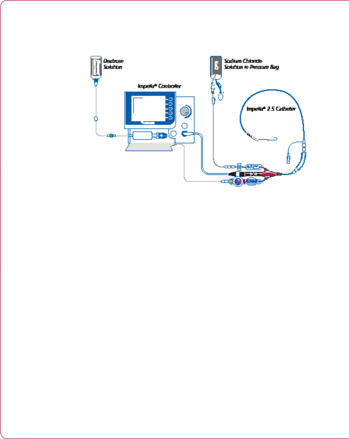
Figure 3.2 illustrates how the Impella® Controller connects to the Impella® 2.5 and accessory
components.
Figure 3.2 Impella® Controller, Impella 2.5, and Accessories
3.3
Impella® Controller with Impella® 2.5
IMPELLA® 2.5 CATHETER
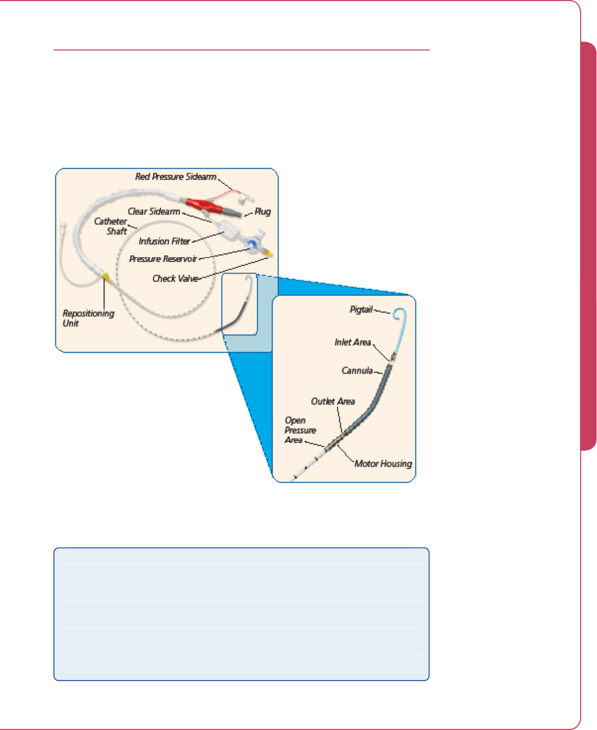
The Impella® 2.5 Catheter is an intravascular microaxial blood pump that delivers up to 2.5
liters of blood per minute from the left ventricle into the aorta. Figure 3.3 illustrates the
Impella® 2.5 Catheter. Table 3.1 describes each component from the pigtail at one end to the
check valve on the other end.
Figure 3.3 Impella® 2.5 Catheter
Table 3.1 Impella® 2.5 Catheter Components
Component Description
Pigtail The 6 Fr pigtail is attached to the cannula at the distal end of the inlet
area. It assists with stabilizing the catheter in the correct position in
the left ventricle.
Cannula The 12 Fr cannula has a spiral-shaped reinforced body that is shaped in
a 45-degree angle.
Inlet area The inlet area, where the blood enters the cannula, is located at the
distal tip of the cannula.
Outlet area The proximal end of the cannula is attached to the outlet area where
the blood exits the cannula.
3 THE IMPELLA® 2.5 AND IMPELLA® CONTROLLER

3.4 Instructions for Use
Table 3.1 Impella® 2.5 Catheter Components (cont’d)
Component Description
Motor housing The motor housing is 12 Fr in diameter and consists of a completely
encapsulated motor.
Open pressure area The open pressure area is an opening located between the motor
housing and the distal end of the catheter shaft.
Catheter shaft A 9 Fr catheter shaft is located between the motor housing and
the plug. The lumen of the catheter shaft contains a purge lumen,
a pressure measurement lumen, and a pump monitoring cable.
The catheter shaft has longitudinal and transversal marks:
• The longitudinal marks along the inner radius of the cannula show
the position of the curved, flexible cannula.
• The transversal marks at 1 cm intervals aid in proper positioning.
Repositioning unit The repositioning unit consists of an introducer and an
anticontamination sleeve with an anchoring ring.
• The introducer (with hemostatic valve) is graduated from 11 Fr to
15 Fr. It is located on the catheter shaft and allows repositioning of
the catheter.
• The anchoring ring of the anticontamination sleeve secures the
catheter sheath to the introducer.
Plug The plug at the proximal end of the catheter connects the catheter to
the Impella® Controller through a connector cable. It has two sidearms:
a red pressure sidearm and a clear sidearm.
Red pressure sidearm The red pressure sidearm is attached to a standard pressure bag and is
used to prime the line of the pressure measurement system.
Clear sidearm The clear sidearm is attached to the purge cassette purge line. It leads
to the infusion filter, the pressure reservoir, and the check valve.
Infusion filter The infusion filter prevents bacterial contamination and prevents air
from entering the catheter.
Pressure reservoir The pressure reservoir includes a flexible rubber diaphragm that
provides additional filling volume by means of an expansion chamber
during purge solution change.
Check valve The yellow check valve ensures that purge fluid does not flow in the
reverse direction when the purge solution is exchanged.
3.5
Impella® Controller with Impella® 2.5
IMPELLA® CONTROLLER
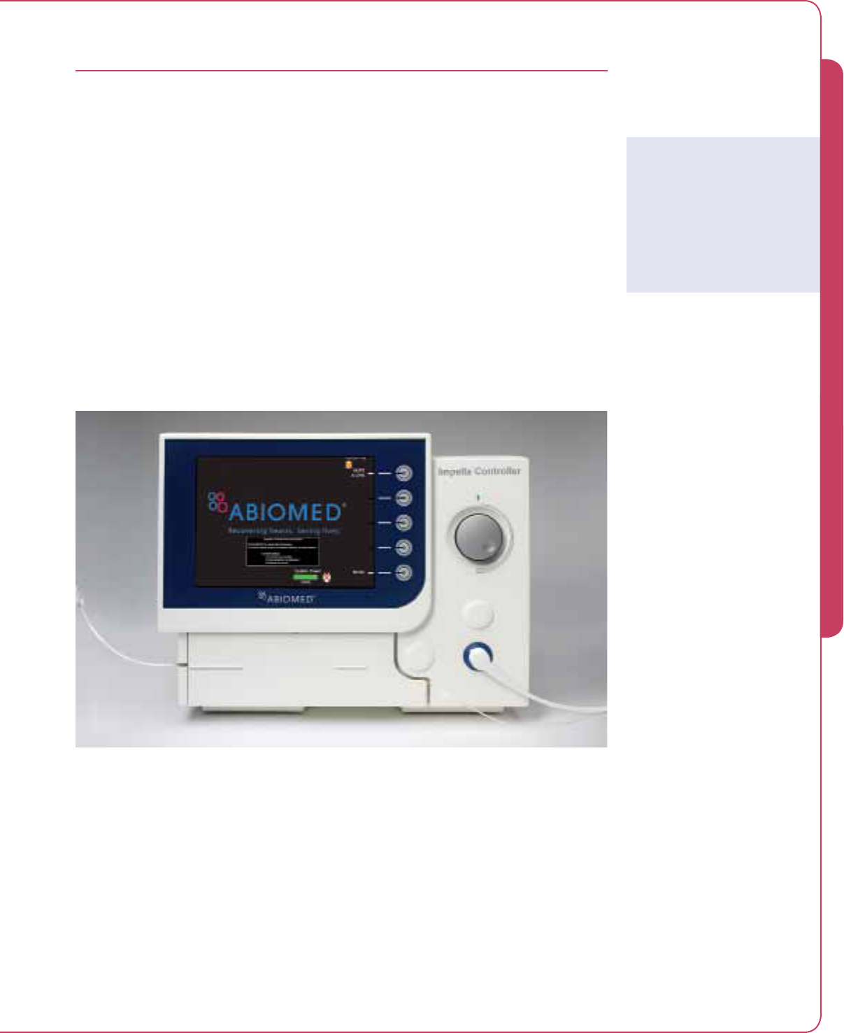
The Impella® Controller (see Figure 3.4) provides three vital functions to the operation of the
Impella® 2.5:
• The controller provides an interface for monitoring and controlling the function of the
Impella 2.5
• The controller provides a uid purge to the Impella 2.5 motor
• The controller provides backup power when the controller is operated away from AC
power
The controller weighs 26 lbs (11.8 kg) and can operate on its internal battery for at least 60
minutes when fully charged.
Impella® Controller operation is described in detail in Section 4 of this manual.
Figure 3.4 Impella® Controller – Front View
Impella® Controller
Battery Power
The controller can operate
on its internal lithium-ion
(Li-Ion) battery for at least 60
minutes when fully charged.
3 THE IMPELLA® 2.5 AND IMPELLA® CONTROLLER
3.6 Instructions for Use
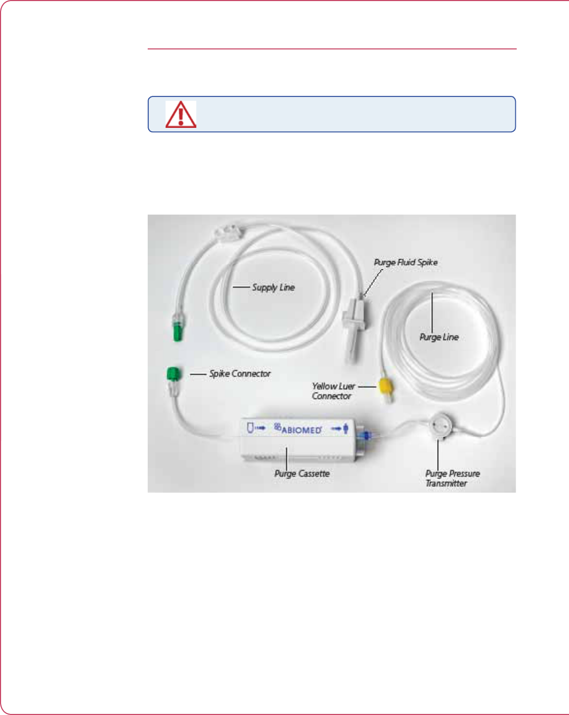
PURGE CASSETTE
Do not use saline in the purge system.
The purge cassette delivers rinsing fluid to the Impella® pump. The purge fluid (typically 20%
dextrose solution plus heparin 50 IU/mL) flows from the purge cassette through the catheter to
the microaxial blood pump to prevent blood from entering the pump motor. Figure 3.5 illustrates
the purge cassette and related components. Table 3.2 describes each component.
Figure 3.5 Purge Cassette

3.7
Impella® Controller with Impella® 2.5
Table 3.2 Purge Cassette Components
Component Description
Purge cassette Contains the components for circulating the purge fluid; maintains the
pressure barrier between the blood and the motor at the proper level
Purge pressure
transmitter
Contains a membrane that transmits pressure to the controller based
on the purge pressure in the purge line; a transducer in the controller
measures the pressure so that it can be displayed on the screen
Purge line Carries purge fluid from the purge cassette to the Impella® pump
Yellow luer connector Connects the purge line to the pressure reservoir (yellow luer lock) on
the Impella® pump
Purge fluid spike One end spikes the purge fluid bag and the other end connects the
bag to the purge cassette supply line
Spike connector Connects the purge cassette supply line to the purge fluid spike
Supply line Carries fluid from the purge fluid bag to the purge cassette
3 THE IMPELLA® 2.5 AND IMPELLA® CONTROLLER
3.8 Instructions for Use
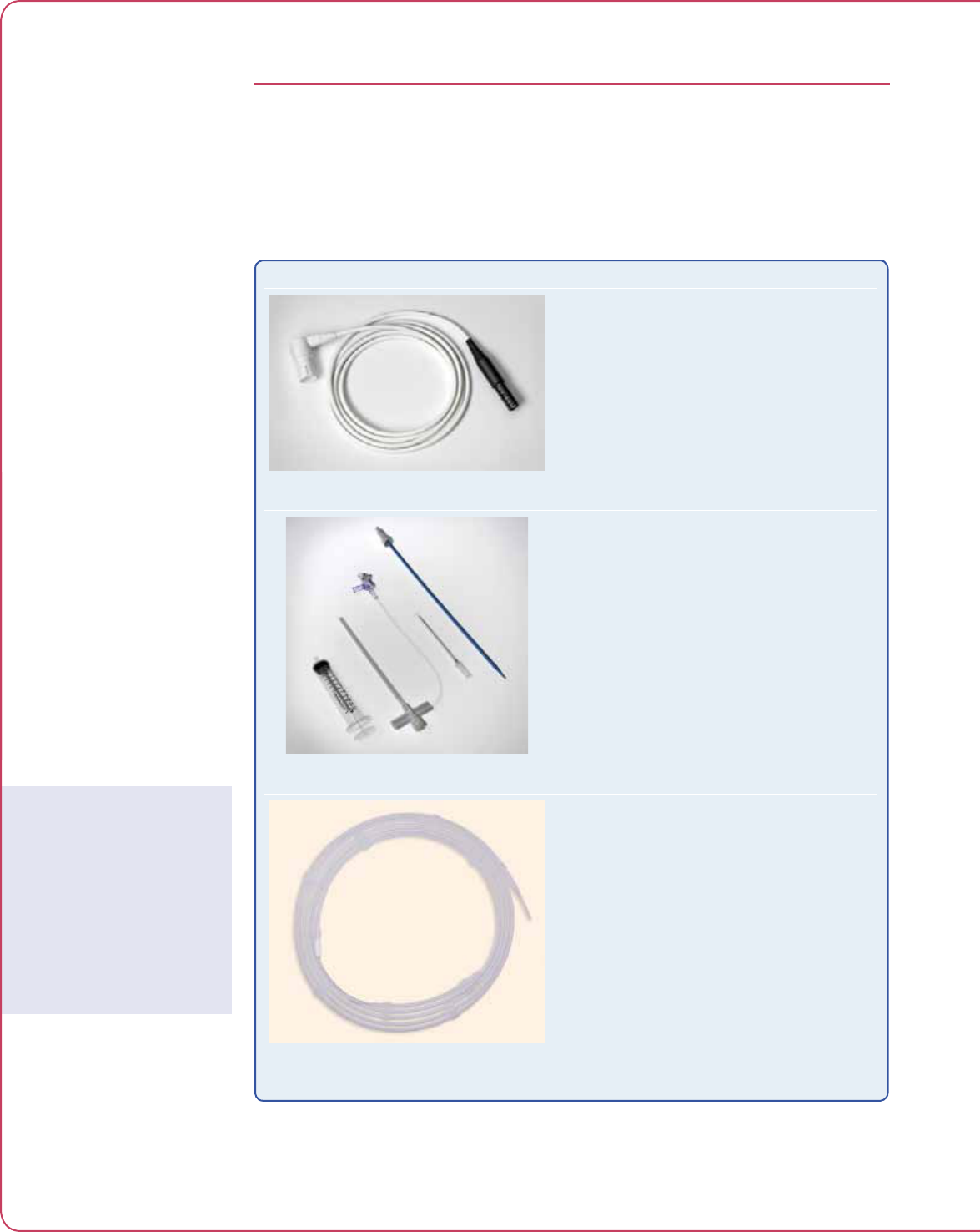
ACCESSORIES
Table 3.3 illustrates and describes the accessories used with the Impella® 2.5 and Impella®
Controller.
Table 3.3 Impella® 2.5 and Impella® Controller Accessories
Component Description
Figure 3.6 White Connector Cable
The white connector cable connects the Impella®
2.5 Catheter to the Impella® Controller. The
connector cable is attached to the Impella® pump
in the original packaging.
• The socket at the black end of the cable
connects to the Impella® catheter plug.
• The white plug at the opposite end of the cable
is inserted into the blue pump plug on the front
of the Impella® Controller.
Figure 3.7 Introducer Kit
The introducer kit is used to position the pump.
It contains:
• 13 Fr peel-away introducer with hemostatic valve
• 13 Fr dilator
• 18 G Seldinger needle
• 10 cc syringe
• 0.035 in stiff guidewire
Figure 3.8 0.018 in/260 cm Placement
Guidewire
The 0.018 in/260 cm placement guidewire is used
for the placement of the catheter. The guidewire
has a radiopaque, shapable tip.
Guidewire Use
It is important to use only
the guidewire supplied with
the system or an Abiomed-
approved alternative. Refer
to Appendix C for more
information about Abiomed-
approved guidewires.

3.9
Impella® Controller with Impella® 2.5
Component Description
Figure 3.9 20% Dextrose in Water
20% dextrose solution with 50 IU/mL of heparin is
used as the purge fluid. The purge cassette infuses
the purge fluid through the catheter.
Figure 3.10 Impella® Controller Cart
The Impella® Controller Cart holds the Impella®
Controller. The cart has wheels for easy transport
of the controller and a storage basket.
3 THE IMPELLA® 2.5 AND IMPELLA® CONTROLLER

4 USING THE IMPELLA® CONTROLLER
OVERVIEW ....................................................................................................4.1
IMPELLA® CONTROLLER FEATURES............................................................. 4.2
IMPELLA® CONTROLLER HOME SCREEN DISPLAY ...................................... 4.4
IMPELLA® CONTROLLER WAVEFORM SCREEN DISPLAY ..............................4.7
Placement Signal Waveform.............................................................................4.7
Motor Current Waveform .................................................................................4.8


4.1
Impella® Controller with Impella® 2.5
OVERVIEW
The Impella® Controller is the primary user control interface for the Impella® 2.5. It controls
the pump performance, monitors the Impella® 2.5 for alarms, and provides real time catheter
position information regarding the location of the pump across the aortic valve. The controller
can be powered by AC power or can operate on internal battery power for at least 60 minutes
when fully charged.
This section of the manual discusses Impella® Controller features and displays.
4 USING THE IMPELLA® CONTROLLER

4.2 Instructions for Use
IMPELLA® CONTROLLER FEATURES
Figure 4.1 illustrates the features of the Impella® Controller. These features are described
in Table 4.1.
Figure 4.1 Impella® Controller Features – Front and Side Views

4.3
Impella® Controller with Impella® 2.5
Table 4.1 Impella® Controller Features
Feature Description
Display screen Displays user information, including the labels for the soft buttons.
(Display screen elements described in detail later in this section.)
Soft buttons Display, open, navigate, and close menus. The function for each soft button is
defined by labels adjacent to the button on the display screen; function changes
depending on the screen. (Soft button functions are described in Table 4.2)
When the pump is running the default soft button labels are as follows:
• MUTE ALARM
• TARGET FLOW
• DISPLAY
• PURGE SYSTEM
• MENU
Selector knob Rotating push button; turn clockwise and counterclockwise to scroll through
menu items; push to make a selection.
NOTE: In many situations, selector knob function is circular—that is, once
you scroll to the end of the list of selections, the system circles through the
list again as you continue to turn the knob. On some screens, however, the
selector knob function is NOT circular and you must turn the knob in the
reverse direction to get to previous items.
Pump plug Connection point on the controller for the Impella® pump
Purge cassette
door
Spring-loaded door that opens to provide access to the purge cassette
Purge cassette Contains the components for circulating purge fluid; maintains the pressure
barrier between the blood and the motor at the proper level. (The purge
cassette and its components are described in Section 3 of this manual.)
Purge pressure
transmitter
Applies pressure to the transducer in the controller so that purge presure can
be measured
Bed mount Metal bracket on the back of the controller; attaches controller to the bed
Purge cassette
door release
Located on the left side of the controller; press to open the purge cassette
door
RS-232 service
jack
Interface for data transfer to an external device
USB connector Connection for downloading data
Ethernet jack Connection for downloading data or software upgrades
Equipotential
ground stud
Used to ground the Impella® Controller according to hospital procedures
AC fuses Electrical safety device in the event of current overload
Power cord
retainer
mounting holes
For mounting power cord retainer
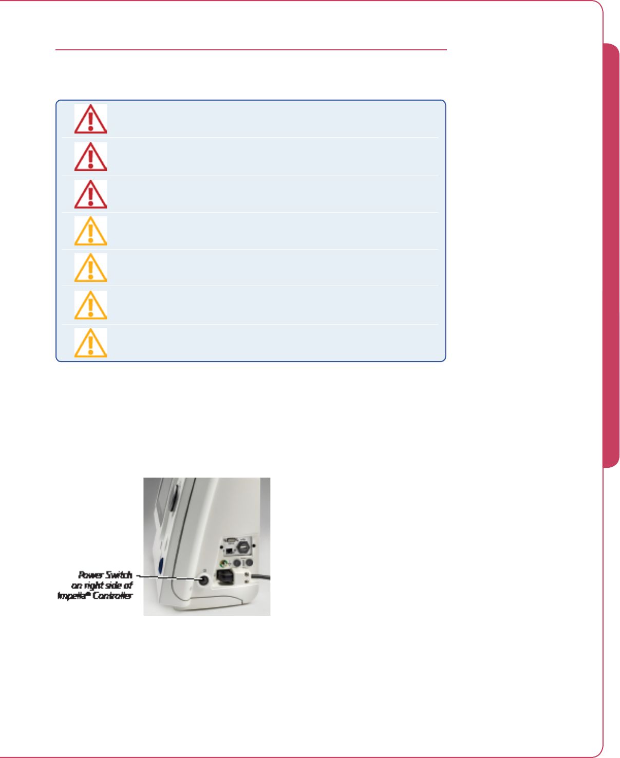
Power switch Turns the controller ON or OFF
• ON: Press and hold the power switch key for 3 seconds
• OFF: (1) Disconnect the Impella® Catheter from the Impella® Controller.
(2) Press and hold the power switch for 3 seconds.
(3) Press OK to confirm that the controller should be turned off.
NOTE: Holding down the power switch for longer than 30 seconds during
operation will cause the controller to initiate hardware switch-off
AC plug Connection point on the controller for the AC power cord
4 USING THE IMPELLA® CONTROLLER
4.4 Instructions for Use
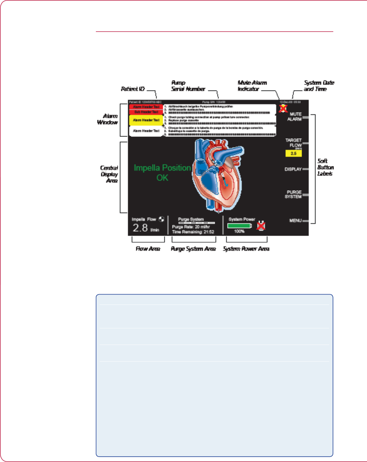
IMPELLA® CONTROLLER HOME SCREEN DISPLAY
The home screen displays operating parameters and information for the entire system.
Figure 4.2 illustrates the Impella® Controller home screen display. Each element of the display is
described in Table 4.2.
Figure 4.2 Impella® Controller Home Screen Display
Table 4.2 Impella® Controller Display Elements
Display Element Description
Patient identification (ID) Displayed in the upper left corner of the display screen if the
information has been entered. The Patient ID can be up to 31
characters in length.
Pump serial number Displayed in the upper center of the display screen if a blood pump is
connected to the controller.
System date and time The current date and time (24-hour format) are displayed in the upper
right corner of the screen display.
Alarm window The alarm window displays up to 3 alarms simultaneously, in order of
priority from top to bottom.
For each alarm, the alarm window displays:
• Alarm header – displayed in the left column; window is color-
coded red for critical alarms, yellow for warning alarms, white for
advisory notifications, gray for resolved alarms
• Alarm subhead (if applicable) – further describes the alarm
condition
• Detailed text – up to 3 lines of instructions for resolving the alarm
condition are displayed in the right column of the alarm window
next to the alarm header and subhead information
(See Section 10 of this manual for further discussion of Alarms.)

4.5
Impella® Controller with Impella® 2.5
Table 4.2 Impella® Controller Display Elements (cont’d)
Display Element Description
Supply line Carries fluid from the purge fluid bag to the purge cassette
Mute Alarm indicator Displayed below the system date and time in the upper right
of the display screen. (See Section 10 of this manual for more
information about the Mute Alarm function.)
• Yellow bell with red X displayed when an alarm is muted.
• Not displayed when an alarm is active but not muted or when
there are no active alarms.
Soft button labels The soft buttons on the Impella® Controller have corresponding
labels adjacent to them on the display screen. These labels change
depending on the type of screen displayed.
MUTE ALARM
• Mutes (silences) active alarms
TARGET FLOW (or NEXT)
• TARGET FLOW – Brings up the target flow icon, which
enables users to set the current flow rate for the Impella 2.5
• NEXT – Advances to the next screen
DISPLAY (or BACK)
• DISPLAY – Brings up the Display menu for viewing
waveforms and navigating to other screen displays
• BACK – Returns to the previous screen
PURGE SYSTEM (or EXIT)
• PURGE SYSTEM – Brings up the Purge System menu for
making changes in purge fluid, purge cassette, or the purge
system, or de-airing the purge system
• EXIT – Exits the current procedure
MENU (or Exit Repositioning Guide)
• MENU – Brings up a menu of options related to controller
settings, alarm history, repositioning, and starting a
procedure
• Exit Repositioning Guide – Exits the repositioning guide
System power area System power information is displayed to the right of the purge
system information on the bottom of the display screen
Battery status
• Bar within battery symbol indicates the overall remaining
capacity of the batteries
• Full green bar for fully charged battery
• Partial green bar for battery that is at least 50% charged
• Partial yellow bar for battery that is between 25% and 50%
charged
• Partial red bar for battery that is less than 25% charged
• Moving gray bar indicates battery is in charging mode
• Numeric percentage of battery power remaining displayed
below the battery icon
AC plug indicator
• Green plug symbol indicates that the controller is running on AC
power
• Gray plug icon with a red X indicates no AC power detected
and the controller is running on battery power
4 USING THE IMPELLA® CONTROLLER

4.6 Instructions for Use
Table 4.2 Impella® Controller Display Elements (cont’d)
Display Element Description
Purge system area Information about the purge system is displayed to the right of
the flow area at the bottom of the display screen
Purge system marquee
• Strobes from left to right when the purge system is operating
• Slow strobing represents normal purge ow rate
• Fast strobing represents bolus ow rate
Purge rate
• Current purge rate displayed in mL/hr below the purge system
marquee if the purge rate is known
• Not displayed if there is no purge cassette or the procedure has
not yet started
Time remaining in reservoir
• Displays the remaining runtime based on the volume of the
purge fluid bag at the start of the case and the cumulative time
and flow rate of delivery of purge fluid
• Not displayed if there is no purge cassette or the procedure has
not yet started
Flow area Information about Impella® flow is displayed in the lower left
corner of the display screen
Current flow rate
• Mean pump ow displayed in liters per minute (L/min)—
the numbers appear in white if the pump position is correct;
yellow if the pump position is incorrect or unknown
• If the system is unable to calculate ow, a yellow triangular
caution icon is displayed with the message “Flow Calculation
Disabled”
Pump icon
• The circular pump icon rotates when the blood pump is running
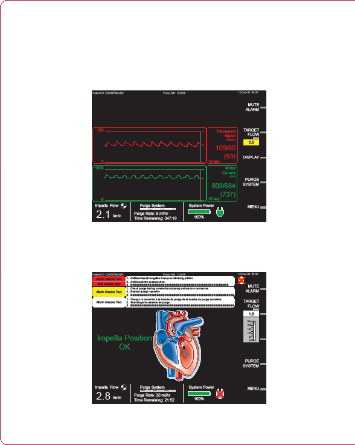
Central display area On the home screen, the central display area displays a heart
pictogram and Impella® position indicator message.
Heart pictogram appears in the center of the home screen display
• Provides a visual representation of the current Impella® pump
position
• Overlaid with a translucent yellow “?” when the controller
detects an incorrect pump position or cannot detect pump
position
Impella® position indicator message displayed to the left of the
heart image
• Displays “Impella® Position OK” in green when pump position
is correct
• Displays “Impella® Position Unknown” in yellow when pump
position is unknown
• Displays specic message in yellow when pump position is
incorrect
4.7
Impella® Controller with Impella® 2.5
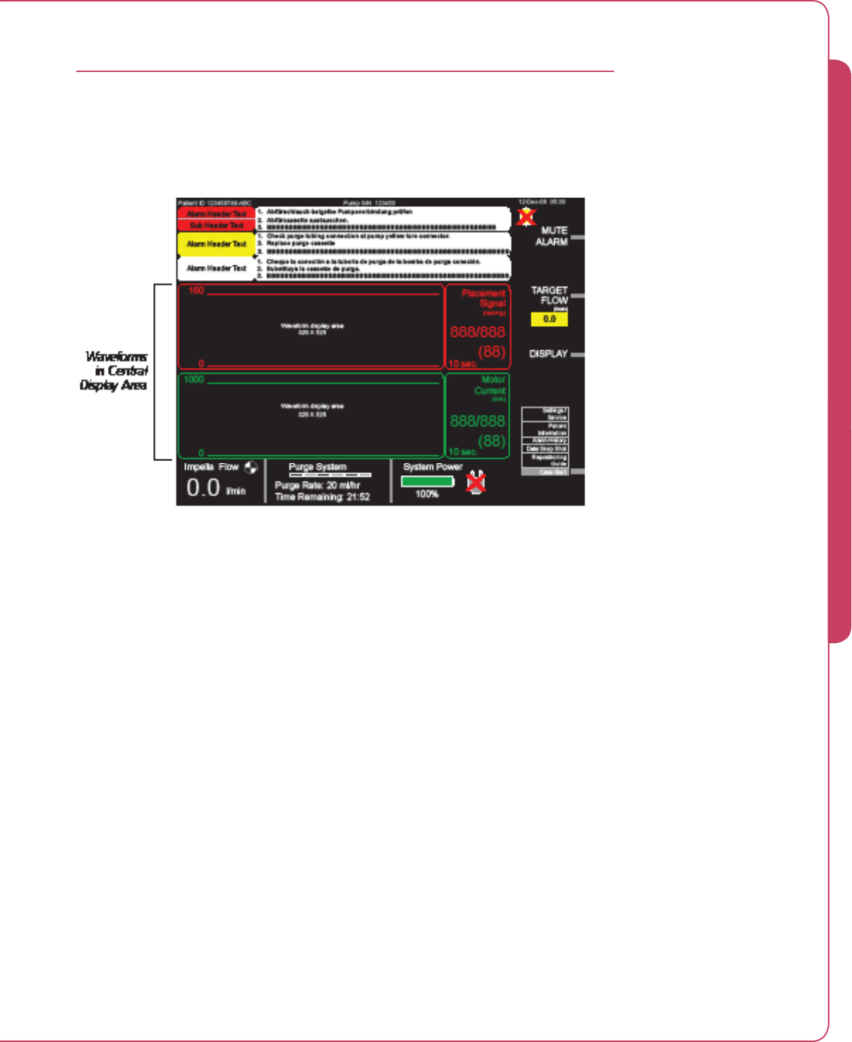
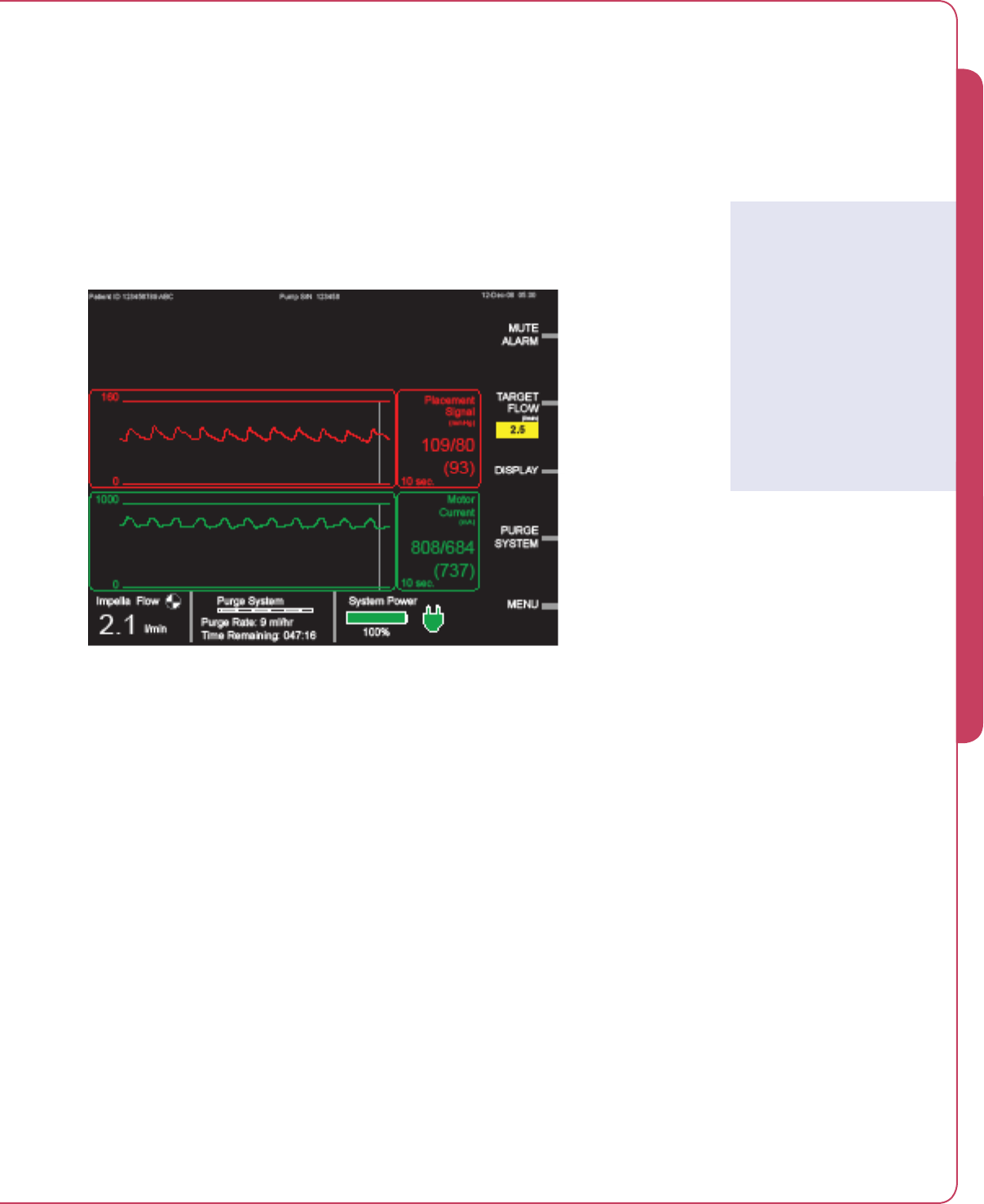
IMPELLA® CONTROLLER WAVEFORM SCREEN DISPLAY
The waveform screen (see Figure 4.3) displays operating data for the system. The screen displays
up to two waveforms and current pump data in the central display area of the screen.
Figure 4.3 Waveform Screen Display (Waveform TBD)
Figure 4.3 shows two time-based waveform signals from different sources.
• Placement signal waveform
• Motor current waveform
PLACEMENT SIGNAL WAVEFORM
The placement signal waveform displays a pressure measurement that corresponds to the
location of the open pressure area of the catheter. The placement signal is used to verify the
position of the microaxial blood pump by evaluating the current pressure waveform as an aortic
or ventricular waveform. The scale for the placement signal waveform is displayed to the left of
the waveform. The default scaling is 0–160 mmHg in 20 mmHg increments, with a minimum
upper limit of 100 mmHg and a maximum upper limit of 240 mmHg for the Impella 2.5.
To the left of the waveform is a display that labels the waveform, provides the units of
measurement, shows the upper and lower range values, and the average value from the samples
received from the last value update. At the bottom of that window is the time scale, which can
be set to 10 seconds, 5 minutes, or 5 hours using the DISPLAY soft button. The default time
scale is 10 seconds.
4 USING THE IMPELLA® CONTROLLER

4.8 Instructions for Use
MOTOR CURRENT WAVEFORM
The motor current waveform is a measurement of the electricity through the pump motor. The
scale for the motor current waveform is displayed to the left of the waveform. The default scaling
is 0–1000 mA in 100 mA increments for the Impella 2.5, with a minimum difference between
upper and lower limits of 200 mA and a maximum difference of 1000 mA.
To the left of the waveform is a display that labels the waveform, provides the units of
measurement, shows the upper and lower range values, and the average value from the samples
received from the last value update. The time scale at the bottom of that window can be set
to 10 seconds, 5 minutes, or 5 hours using the DISPLAY soft button. The default time scale
is 10 seconds.
Motor Current
Motor current is the
measurement of electricity
through the Impella® motor
required to rotate the
Impella® microaxial pump.

1
STARTUP .......................................................................................................5.1
Turning ON the Impella® Controller .................................................................. 5.1
The Startup Screen ..........................................................................................5.2
Starting a Case Procedure................................................................................5.2
CASE START ..................................................................................................5.3
Overview .........................................................................................................5.3
Initial Setup .....................................................................................................5.3
Prime Purge Tubing .........................................................................................5.4
Enter Purge Fluid Data .....................................................................................5.5
Plug Impella® into Controller ...........................................................................5.6
Prime Impella® Purge Lumen ...........................................................................5.6
Prime Blood Pressure Lumen ............................................................................5.7
Pre-Insertion Impella® Test ..............................................................................5.7
Impella® Test Successful ..................................................................................5.7
INSERTING THE IMPELLA® 2.5 CATHETER ...................................................5.8
POSITIONING AND STARTING THE IMPELLA® 2.5 CATHETER ....................5.11
USE OF THE REPOSITIONING INTRODUCER
AND THE 13 Fr PEEL-AWAY INTRODUCER ..................................................5.14
PURGER PROCEDURES ...............................................................................5.15
Purge System Change .................................................................................... 5.15
Purge Fluid Change ....................................................................................... 5.16
Purge Cassette Change ................................................................................. 5.16
De-Air Purge System ...................................................................................... 5.17
TROUBLESHOOTING THE PURGE SYSTEM ..................................................5.18
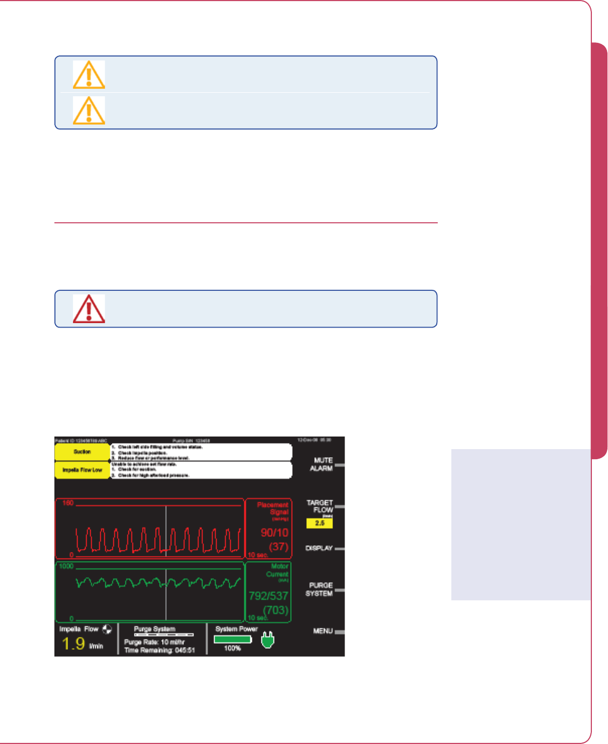
Low Purge Pressure ....................................................................................... 5.18
High Purge Pressure ...................................................................................... 5.18
Purge System Blocked .................................................................................... 5.18
PATIENT WEANING .....................................................................................5.19
Rapid Weaning .............................................................................................. 5.19
Slow Weaning ............................................................................................... 5.19
5 USING THE IMPELLA® CONTROLLER
WITH THE IMPELLA® 2.5

5.1
Impella® Controller with Impella® 2.5
STARTUP
Do
NOT
use an Impella® 2.5 System if any part of the system is damaged.
The sterile components of the Impella® 2.5 System can be used only if the
sterilization indicators show that the contents have been sterilized, the packaging is
not damaged, and the expiration date has not elapsed.
Do
NOT
resterilize or reuse the Impella® 2.5 Catheter. It is a disposable device and
is intended for single use only.
To prevent malfunction of the Impella® Controller, avoid long-term exposure to
direct sunlight and excessive heat (40°C).
To prevent overheating and improper operation, do NOT block the cooling vents of
the Impella® Controller while it is operating.
The Li-Ion batteries must be charged for 10 hours prior to system operation. After
being unplugged, the Impella® Controller will operate for at least 60 minutes after
the batteries have been fully charged.
Have a backup Impella® Controller available in the unlikely event of controller
failure.
TURNING ON THE IMPELLA® CONTROLLER
To turn the controller ON:
1. Press and hold the power switch on the right side of the Impella® Controller for 3
seconds (see Figure 5.1).
Figure 5.1 Impella® Controller Power Switch
The Impella® Controller automatically performs a system test when turned ON.
A display bar shows the progress of the system test. If the system test passes, the system
displays the startup screen (see Figure 5.2).
5 USING THE IMPELLA® CONTROLLER WITH THE IMPELLA® 2.5

5.2 Instructions for Use
If the system test fails, the controller displays a system self check failure message:
SYSTEM SELF CHECK FAILED.
CHANGE CONSOLE IMMEDIATELY.
The controller displays the reason for the system test failure at the bottom of the screen.
THE STARTUP SCREEN
The startup screen (Figure 5.2) appears when you successfully turn ON the Impella® Controller.
Figure 5.2 Impella® Controller Startup Screen
The startup screen displays:
• The current status of the Impella® pump (currently no pump connected to the Impella®
Controller in Figure 5.2).
• The current status of the purge cassette (no purge cassette detected in Figure 5.2).
• The current version of the software that the Impella® Controller is running.
The startup screen also displays system power information along the bottom of the screen and
two active soft buttons—MUTE ALARM and MENU—along the right side of the screen.
STARTING A CASE PROCEDURE
To start a case procedure:
1. Press the MENU soft button from the startup screen.
2. Scroll the selector knob to “Case Start” on the pop-up menu that appears on the screen.
3. Press the selector knob to select “Case Start”.
After you press the selector knob to select “Case Start” from the menu, the controller displays
an 8-screen series that leads you from initial setup through the pre-insertion Impella® test.
5.3
Impella® Controller with Impella® 2.5
CASE START
Fluoroscopy is required to guide placement of the Impella® 2.5. The small
placement guidewire must be reliably observed at all times.
The sterile components of the Impella® 2.5 System can be used only if the
sterilization indicators show that the contents have been sterilized, the packaging is
not damaged, and the expiration date has not elapsed.
Do
NOT
remove the Impella® 2.5 Catheter over the length of the guidewire.
Handle with care. The Impella® 2.5 Catheter can be damaged during removal from
packaging, preparation, insertion, and removal. Do
NOT
bend, pull, or place excess
pressure on the catheter or mechanical components at any time.
Do
NOT
touch the inlet or outlet areas of the catheter and avoid manual
compression of the inlet cannula assembly while placing the device.
Do not kink or clamp the Impella® 2.5 Catheter or the 13 Fr peel-away introducer.
OVERVIEW
You will need the following materials to complete the setup before starting the case:
• 500 cc bag of D20 with 50 IU of heparin per cc. (Recommended)
• IV ush solution (NaCl) with pressure bag and 96 inches of sterile infusion line.
NOTE: The distal end of the infusion line must remain sterile.
The Impella® Controller displays eight screens of instructions to lead you through a case start:
• Initial setup
• Prime purge tubing
• Enter purge uid data
• Plug Impella® into controller
• Prime Impella® purge lumen
• Prime blood pressure lumen
• Pre-insertion Impella® test
• Impella® test successful
INITIAL SETUP
1. Open the purge cassette package.
2. Using sterile technique, connect the purge fluid spike to the spike connector on the
end of the purge fluid supply line. Secure the yellow luer connector and pass the purge
cassette and supply line to the Impella® Controller operator.
Sensitive Medical Device
The Impella® 2.5 Catheter
is a sensitive medical device
with a microaxial pump with
extremely fine tolerances.
In particular, the inflow and
outflow areas of the distal
and proximal areas of the
pump assembly may be
damaged if subjected to
strong external forces.
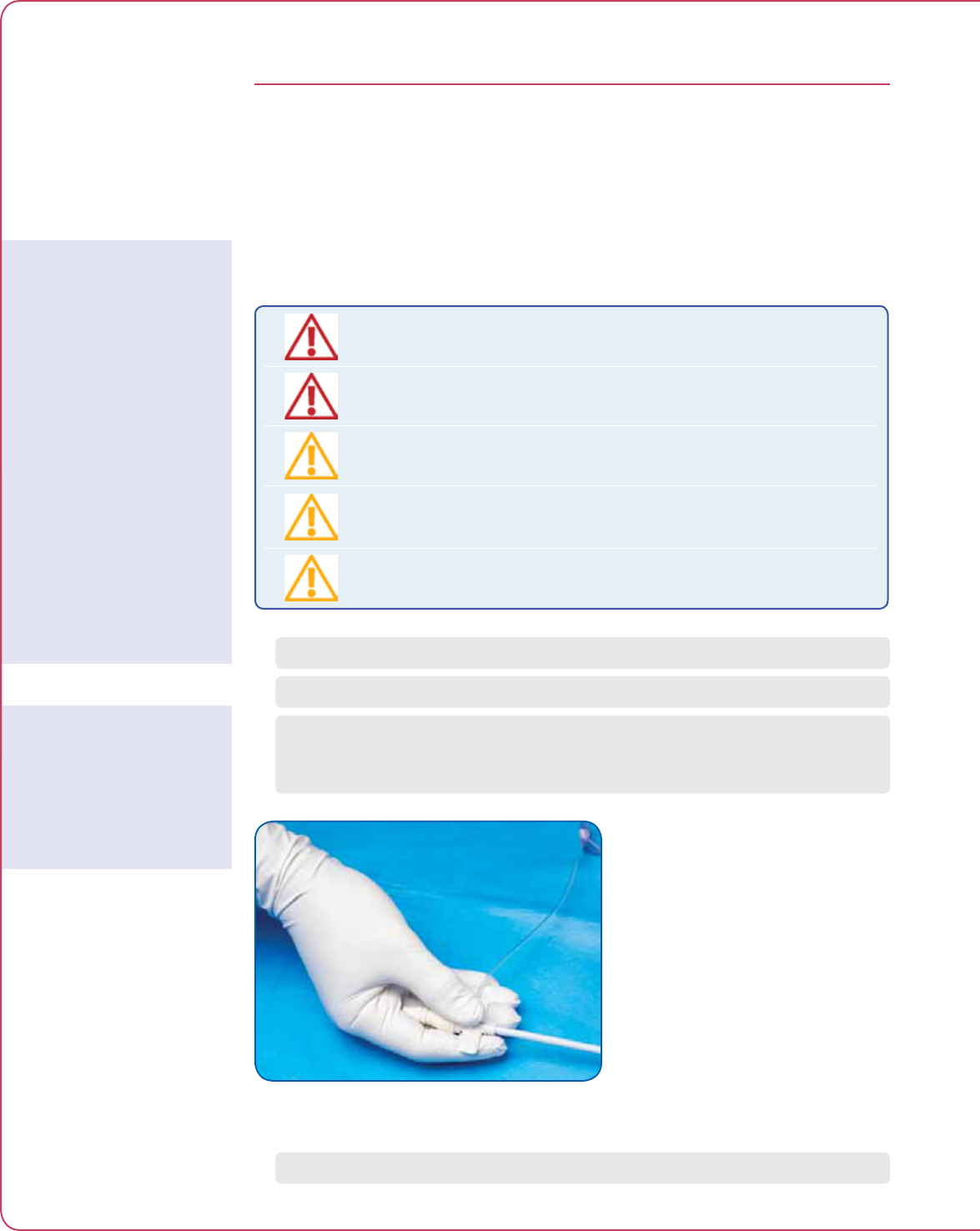
Shaded Steps
All shaded steps require sterile
technique.
5 USING THE IMPELLA® CONTROLLER WITH THE IMPELLA® 2.5
5.4 Instructions for Use
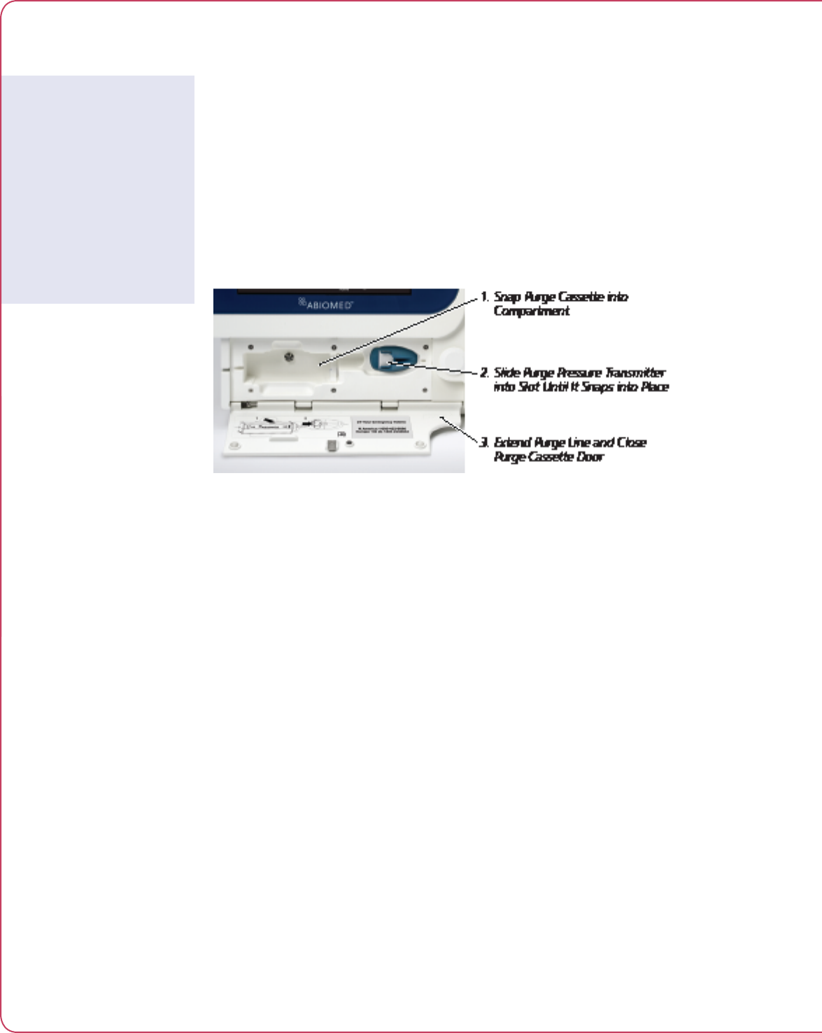
3. Open the purge cassette door by pressing the release on the left side of the controller.
Insert the purge cassette into the Impella® Controller (as shown in Figure 5.3).
• The purge cassette snaps into a molded compartment on the front of the controller.
Follow the diagram on the inside of the purge cassette door for proper placement.
• Slide the purge pressure transmitter into the slot to the right of the purge cassette
until it snaps into place.
• Extend the purge line and close the purge cassette door. There is sufcient room
around the edges of the purge cassette door so that it will not pinch the purge line as
it exits.
Figure 5.3 Inserting Purge Cassette into Impella® Controller
4. Spike the purge fluid bag with the purge fluid spike attached to the end of the supply
line and hang the purge fluid bag.
5. Press the NEXT soft button to advance to the next screen.
PRIME PURGE TUBING
1. Use the selector knob to scroll to START on the screen and press the knob to begin
priming the purge line. The controller will start the priming process at a bolus rate of
250 mL/hr or greater.
2. When purge fluid is discharged from the tip of the yellow Impella® connector at the end
of the purge line, scroll to STOP and press the selector knob to stop the flow of purge
fluid.
3. Press NEXT after selecting STOP to proceed to entering purge fluid data.
If you press the BACK button on this screen, the controller will return to step 1 of priming the
purge tubing.
If you do not press STOP within 60 seconds of pressing START, you will get a message that the
purger has stopped. Press BACK if additional purging is required. If the purge fluid has been
discharged from the purge tubing and priming is complete, press NEXT.
Selector Knob Function
The selector knob function
here is NOT circular (you
CANNOT keep turning
the knob in one direction
to scroll between START
and STOP). Turn the knob
clockwise to scroll to STOP
and counterclockwise to scroll
to START.
5.5
Impella® Controller with Impella® 2.5
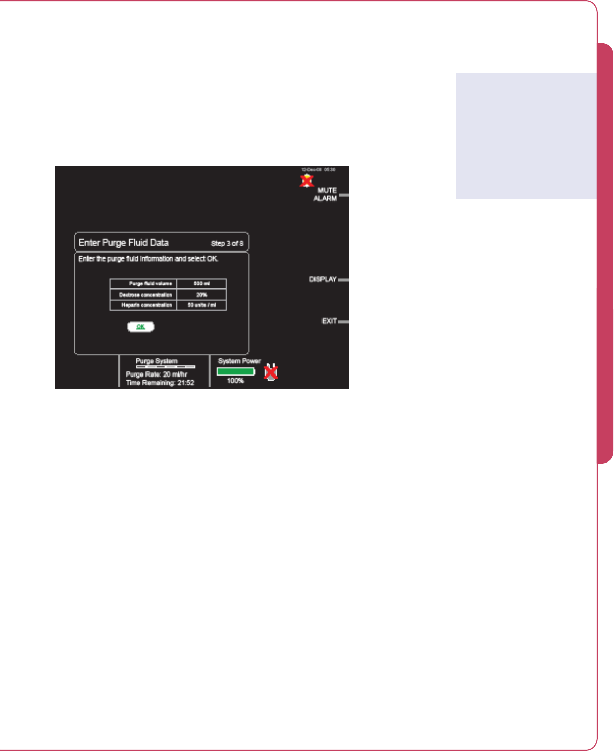
ENTER PURGE FLUID DATA
The Impella® Controller displays a table of recommended default values for the purge fluid
(see Figure 5.4).
1. To select the default values displayed on the screen, scroll to OK below the table and
press the selector knob. This will select those values and automatically advance you to
the next screen.
Figure 5.4 Default Values for Purge Fluid
2. To change the purge fluid information, scroll to the appropriate item push the selector
knob to select it. Then scroll through the values and push the selector knob to make a
new selection. The controller will use the default values if no other selections are made.
• Purge uid can be set to 100 mL, 250 mL, 500 mL (the default), or 1000 mL.
• Dextrose concentration can be set to 5%, 10%, 20% (the default), 30%, or 40%.
• Heparin concentration can be set to 0, 5, 10, 12.5, 15, 20, 25, or 50 units/mL. (50
units/mL is the default.)
System Timeout
The purger will stop after 60
seconds if the user does not
press STOP. If this happens,
press BACK for additional
priming or NEXT if purge fluid
has been discharged.
5 USING THE IMPELLA® CONTROLLER WITH THE IMPELLA® 2.5

5.6 Instructions for Use
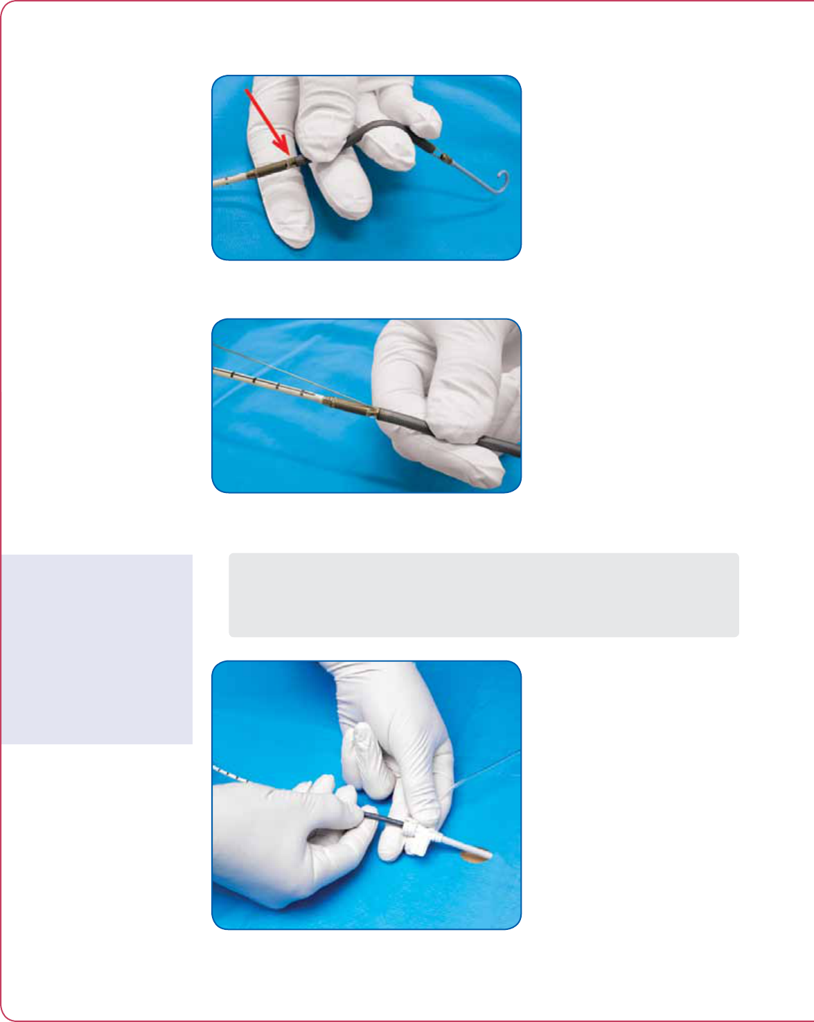
PLUG IMPELLA® INTO CONTROLLER
1. Open the Impella® Catheter package using sterile technique and snap the plastic hook
(located on the pressure reservoir of the clear sidearm) to the connector cable as shown
in Figure 5.5.
Figure 5.5 Snapping Plastic Hook to Connector Cable
2. Pass the sterile white connector cable from the Impella® pump off the sterile field. Line
up the notch on the Impella® connector cable with the notch in the blue pump plug on
the front of the Impella® Controller and plug the cable into the controller.
3. When the Impella® Controller detects that an operational Impella® pump is plugged in,
the Impella® flow icon appears on the screen. The controller automatically advances to
the next screen.
PRIME IMPELLA® PURGE LUMEN
1. Connect the yellow connector on the end of the purge line to the yellow luer connector
on the clear sidearm of the Impella® pump.
2. Select START to begin priming the Impella® purge lumen. The Impella® Controller will
start at a bolus rate of 250 mL/hour or greater.
3. When purge fluid is discharged from the Impella® pump, scroll to and select STOP.
When you press STOP, the bolus stops but purge fluid continues to flow at a low rate.
4. Press NEXT to advance to the next screen.
Important Step
Snapping the plastic hook on
the pressure reservoir to the
connector cable is important
to prevent the tube from
kinking.
Infusion Bag Pressure
If the infusion bag is
underinflated, the progress
bar will not be activated.
If the infusion bag is
overinflated, an alarm
will occur.
If a “Sensor Value not
Reliable” alarm appears while
priming the catheter, check
that the pressurized saline
bag is inflated to a pressure
between 300 and 350 mmHg
and not overinflated.
Time Delay
Expect a 5 to 10 second
time delay after plugging
in the Impella® pump and
before the Impella® Controller
automatically advances to the
next screen.

5.7
Impella® Controller with Impella® 2.5
PRIME BLOOD PRESSURE LUMEN
1. Using sterile technique, connect the flush solution tubing to the red luer connector on
the red sidearm of the Impella® pump.
2. Blood pressure lumen priming starts automatically. Prime the Impella® Catheter
pressure lumen by squeezing the white flush valve until the Impella® Controller beeps.
(see Figure 5.6).
When the system detects the target flush solution pressure within the required amount
of time (60 seconds), the system will go to the next step automatically.
Figure 5.6 Squeezing the White Flush Valve to Prime
the Impella® Catheter Pressure Lumen
PRE-INSERTION IMPELLA® TEST
1. Select TEST to start the pre-insertion Impella® test.
The test runs for 2 seconds. When the system detects that the pump is spinning, it
automatically advances to the next step.
If the pre-insertion test fails, the system will instruct you to unplug the Impella®
from the controller and disconnect the purge and flush lines from the Impella® luer
connectors. You can then press NEXT to set up a new Impella® pump.
IMPELLA® TEST SUCCESSFUL
1. This screen tells you that the Impella® test was successful. Press NEXT to finish Startup.
5 USING THE IMPELLA® CONTROLLER WITH THE IMPELLA® 2.5
5.8 Instructions for Use
INSERTING THE IMPELLA® 2.5 CATHETER
NOTE – Proper surgical procedures and techniques are the responsibility of
the medical professional. The described procedure is furnished for information
purposes only. Each physician must evaluate the appropriateness of the procedure
based on his or her medical training and experience, the type of procedure, and
the type of systems used.
Fluoroscopy is required to guide placement of the Impella® 2.5. The small placement
guidewire must be reliably observed at all times.
To prevent malfunction of the locking mechanism of the 13 Fr peel-away introducer,
do
NOT
hold the hemostatic valve while inserting into the artery.
Do not kink or clamp the Impella® 2.5 Catheter or the 13 Fr peel-away introducer.
Handle with care. The Impella® 2.5 Catheter can be damaged during removal from
packaging, preparation, insertion, and removal. Do
NOT
bend, pull, or place excess
pressure on the catheter or mechanical components at any time.
Do
NOT
touch the inlet or outlet areas of the catheter and avoid manual
compression of the inlet cannula assembly while placing the device.
1. Obtain access to the femoral artery.
2. Insert a 6–8 Fr introducer over the 0.035 guidewire (provided) to pre-dilate the vessel.
3. Remove the 6–8 Fr introducer over the 0.035 guidewire and insert the 13 Fr peel-away
introducer with dilator (see Figure 5.7). While inserting the 13 Fr introducer, hold the
shaft of the introducer to slide it into the artery.
Figure 5.7 Inserting the 13 Fr Peel-Away Introducer
4. Administer heparin. When the ACT is above 250, remove the 13 Fr dilator.
Use Fluoroscopy for
Placement
Impella® 2.5 performance
will be compromised if
correct placement cannot
be confirmed. While
other imaging techniques,
such as transesophageal
echocardiography (TEE), can
help confirm the position
of the Impella® 2.5 after
placement, TEE does not
allow visualization of the
entire catheter assembly and
is inadequate for reliably
placing the Impella® 2.5
across the aortic valve.
Maintaining ACT
After insertion of the catheter
(and until explant), ACT
should be maintained at 160
to 180 seconds.

5.9
Impella® Controller with Impella® 2.5
5. Insert a 6 Fr diagnostic catheter with diagnostic guidewire with no side holes (Judkins
Right, Multipurpose, or pigtail recommended, see Figure 5.8) into the 13 Fr introducer
and advance it over a diagnostic guidewire into the left ventricle.
Figure 5.8 Inserting the 6 Fr Diagnostic Catheter
6. Remove the diagnostic guidewire and insert the supplied 0.018 in/260 cm placement
guidewire.
7. Advance the placement guidewire into the left ventricle until the floppy end and 3 to
4 cm of the stiffer part of the guidewire are visible in the left ventricle.
8. Remove the 6 Fr diagnostic catheter.
9. Wet the cannula with sterile water and backload the pigtail section of the catheter onto
the placement guidewire. One or two people can load the catheter on the guidewire.
One-person technique
a. Advance the guidewire into the Impella® Catheter and stabilize the cannula
between the fingers as shown in Figure 5.9. This prevents pinching of the inlet
port. The guidewire must exit the outlet port on the inner radius of the cannula,
as shown by the arrow in Figure 5.9 and in Figure 5.10. The catheter can be
hyperextended as necessary to ensure the guidewire exits on the inner radius of
the cannula.
Two-person technique
b. The scrub assistant can help stabilize the catheter by holding the catheter proximal
to the motor. This will allow the implanting physician to visualize the inner radius.
The guidewire must exit the outlet port on the inner radius of the catheter, as
shown by the arrow in Figure 5.9 and in Figure 5.10. The physician can focus on
advancing the guidewire and, if the cannula needs to be hyperextended, the scrub
assistant is available to assist.
Impella® 2.5 Use in Open
Heart Surgery
If the Impella® 2.5 is used in
the OR as part of open heart
surgery, manipulation may be
performed only through the
9 Fr steering catheter. Direct
manipulation of the pump
assembly through the aorta or
ventricle may result in serious
damage to the Impella® 2.5
device and serious injury to
the patient.
Avoid Damaging Inflow
Area
During placement of the
Impella® 2.5 device, take
care to avoid damage to the
inflow area while holding
the catheter and loading the
placement guidewire.
5 USING THE IMPELLA® CONTROLLER WITH THE IMPELLA® 2.5
5.10 Instructions for Use
Figure 5.9 Loading the Catheter on the Guidewire
Figure 5.10 Exiting of the Placement Guidewire from the Catheter
10. Advance the catheter through the hemostatic valve into the femoral artery
(see Figure 5.11) and along the placement guidewire into the left ventricle using a fixed-
wire technique. Follow the catheter under fluoroscopy as it is advanced into the left
ventricle, being careful not to coil the guidewire in the left ventricle.
Figure 5.11 Inserting the Impella® 2.5 Catheter
Do NOT Touch Inlet or
Outlet Areas
While feeding the Impella®
through the 13 Fr introducer,
hold the device at the cannula
or motor housing. Do NOT
touch the inlet area or the
outlet area.
5.11
Impella® Controller with Impella® 2.5
To prevent device failure, do not start the Impella® 2.5 Catheter until the guidewire
has been removed.
Do
NOT
remove the Impella® 2.5 Catheter over the length of the guidewire.
11. Remove the placement guidewire.
12. Confirm that a ventricular waveform is displayed on the Impella® Controller.
POSITIONING AND STARTING THE IMPELLA® 2.5
CATHETER
Retrograde flow will occur across the aortic valve if the Impella® 2.5 is set at a flow
rate of 0 L/min.
1. Place the catheter plug at the same level as the patient’s heart.
2. Confirm that a ventricular waveform is displayed on the Impella® Controller
(see Figure 5.12). If a ventricular waveform is not present, gently advance the
catheter forward until a ventricular waveform is present on the placement
signal screen.
Figure 5.12 Ventricular Waveform on Placement Signal Screen
Importance of Proper
Pump Placement
When the pump is not
correctly placed, the patient
does not profit from the flow
rate shown on the controller
and there is no effective
unloading of the ventricle
(hydraulic short circuit).
5 USING THE IMPELLA® CONTROLLER WITH THE IMPELLA® 2.5
5.12 Instructions for Use
3. Pull the catheter back until an aortic waveform is present on the placement signal
screen (see Figure 5.13).
4. When the aortic waveform is present, pull the catheter back an additional 4 cm.
(The distance between adjacent markings on the catheter is 1 cm.) The pump should
now be centered across the aortic valve.
Figure 5.13 Aortic Waveform on Placement Signal Screen
5. Press the TARGET FLOW soft button to open the flow icon (see Figure 5.14)
Figure 5.14 Selecting Target Flow
5.13
Impella® Controller with Impella® 2.5
6. Turn the selector knob to change the flow rate from 0 L/min to 0.5 L/min.
7. Press the selector knob to select the new flow rate.
8. The flow icon in the lower left corner of the screen begins rotating when the Impella®
pump begins to operate.
9. Increase the flow rate to 2.5 L/min to confirm correct and stable placement. Placement
should be verified with fluoroscopy and with the placement signal screen (see Figure
5.15).
Figure 5.15 Confirming Placement on the Placement Signal Screen
10. After correct placement has been achieved, adjust the flow rate to the desired flow.
Flow rates of TBD L/min will default back to TBD L/min after 5 minutes.
11. Reposition the catheter as necessary.
Check Positioning at
Maximum Flow
When the flow rate is
increased to maximum flow,
the device has a tendency
to be drawn into the
ventricle. Check positioning
at maximum flow to ensure
proper placement throughout
the performance level setting
range.
5 USING THE IMPELLA® CONTROLLER WITH THE IMPELLA® 2.5
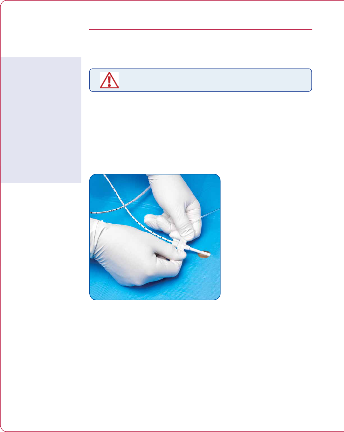
5.14 Instructions for Use
USE OF THE REPOSITIONING INTRODUCER
AND THE 13 Fr PEEL-AWAY INTRODUCER
To prevent failure of the 13 Fr peel-away introducer, remove the 13 Fr peel-away
introducer prior to transport when activated clotting time (ACT) is less than 150
seconds.
1. Flush the sidearm of the repositioning introducer located on the catheter shaft.
2. Carefully flush the sidearm of the 13 Fr introducer and remove the 13 Fr peel-away
introducer completely from the artery over the catheter shaft and apply manual
pressure above the puncture site.
3. Grasp the two “wings” and bend back until the valve assembly comes apart. Continue
to peel the two wings until the introducer is completely separated from the catheter
shaft (see Figure 5.16).
Figure 5.16 Removing the 13 Fr Peel-Away Introducer
4. Attach a stopcock and flush the repositioning sheath prior to advancing the sheath.
5. Place two deadend caps on the stopcock to prevent further usage. The sideport should
not be used to give medication or draw blood because the blood could potentially clot.
Pressure bags should not be connected to the sideport of the repositioning sheath. If
a pressure bag is connected, the sideport must have an infusion pump or flow limiting
valve in place to control the amount of fluid administered to the patient.
6. Slide the repositioning introducer over the catheter shaft and advance it into the artery
to the yellow eyelet.
7. Secure the yellow section of the repositioning introducer by suturing it to the skin using
the provided eyelet.
Alternative to Waiting
Until ACT < 150
If you do not want to wait
until ACT is below 150
seconds before removing
the device, you can remove
the device and exchange the
peel-away sheath with a non
peel-away sheath and dilator
over the wire. Then you
can wait until ACT is below
150 seconds and remove
the sheath without risk of
bleeding.

5.15
Impella® Controller with Impella® 2.5
8. Slide the proximal end of the anticontamination sleeve onto the yellow section of
the repositioning introducer. Lock the anchoring ring in place by turning it clockwise.
Secure the catheter shaft in place by tightening the connected anchoring ring.
9. Carefully extend the anticontamination sleeve to maximum length and secure the end
by tightening the distal anchoring ring.
PURGER PROCEDURES
When replacing the purge cassette, the replacement process must be completed
within 4 minutes. The Impella® 2.5 Catheter may be damaged if replacement takes
longer than 4 minutes.
There are four procedures for maintaining the Impella® purge system:
• Purge system change (cassette and purge uid)
• Purge uid change
• Purge cassette change
• De-air purge system
Each procedure can be accessed using the PURGE SYSTEM soft button.
This section describes each of those purger procedures.
PURGE SYSTEM CHANGE
These are the steps you will follow to change out the purge cassette and purge fluid.
1. The purge system change out procedure begins with delivery of a bolus to the pressure
reservoir so that the reservoir can maintain purge pressure during the change out. After
the bolus is delivered, the controller automatically proceeds to the next screen.
2. Disconnect and remove the used purge cassette. If you do not remove the cassette
within 20 seconds, the system will cancel and exit the purge system change procedure.
3. Insert a new purge cassette into the controller. Be sure to slide the purge pressure
transmitter into place and extend the purge line through the gap in the purge cassette
door when you close the door.
4. Turn the selector knob to select START. Press the knob to begin priming the purge line.
5. When purge fluid is discharged from the purge line, scroll to STOP and press the
selector knob.
6. Press NEXT to advance to the next screen and enter purge fluid information.
7A. To select the default purge fluid values displayed on the screen, scroll to and select OK.
This will select those values and automatically advance you to the next screen.
Replacement Time
If the purge flow is more
than 7 mL/hr or the dextrose
concentration is less than
20%, replacement time
will be less than 4 minutes.
Replacement should always
be performed as quickly as
possible.
5 USING THE IMPELLA® CONTROLLER WITH THE IMPELLA® 2.5

5.16 Instructions for Use
7B. To change the purge fluid information, scroll to the appropriate item and push the
selector knob to select it. Then scroll through the values and push the selector knob to
make a new selection. (Refer to “Entering Purge Fluid Data” in the Startup discussion
at the beginning of this section for a listing of purge fluid, dextrose concentration, and
heparin concentration options.) The controller will use the default values if no other
selections are made.
8. Connect the yellow luer connector on the end of the purge line to the yellow luer
connector on the clear sidearm of the Impella® pump.
9. Press NEXT to exit and complete the procedure.
PURGE FLUID CHANGE
These are the steps you will follow to change only the purge fluid.
1. The purge fluid change procedure begins with delivery of a bolus to the pressure
reservoir so that the reservoir can maintain purge pressure during the change. After the
bolus is delivered, the controller automatically proceeds to the next screen.
2. Replace the purge fluid bag. Press NEXT to advance to the next screen and enter purge
fluid information.
3A. To select the default purge fluid values displayed on the screen, scroll to and select OK.
This will select those values and automatically advance you to the next screen.
3B. To change the purge fluid information, scroll to the appropriate item and push the
selector knob to select it. Then scroll through the values and push the selector knob to
make a new selection. (Refer to “Entering Purge Fluid Data” in the Startup discussion
at the beginning of this section for a listing of purge fluid, dextrose concentration, and
heparin concentration options.) The controller will use the default values if no other
selections are made.
PURGE CASSETTE CHANGE
These are the steps you will follow to change only the purge cassette.
1. The purge cassette change procedure begins with delivery of a bolus to the pressure
reservoir so that the reservoir can maintains purge pressure during the change. After
the bolus is delivered, the controller automatically proceeds to the next screen.
2. Disconnect and remove the used purge cassette. If you do not remove the cassette
within 20 seconds, the system will cancel and exit the purge cassette change
procedure.
3. Insert a new purge cassette into the controller. Be sure to slide the purge pressure
transmitter into place and extend the purge line through the gap in the purge cassette
door when you close the door.
4. Turn the selector knob to select START. Press the knob to begin priming the purge line.
Purge Solution Bottles
If the purge solution is
supplied in bottles, follow the
same procedure as if supplied
in bags.

5.17
Impella® Controller with Impella® 2.5
5. When purge fluid is discharged from the purge line, scroll to STOP and press the
selector knob.
6. Press NEXT to advance to the next screen and connect the purge cassette to the
Impella® pump.
7. Connect the yellow luer connector on the end of the purge line to the yellow luer
connector on the clear sidearm of the Impella® pump.
8. Press NEXT to exit and complete the procedure.
DE-AIR PURGE SYSTEM
These are the steps you will follow to de-air the purge system. This procedure starts
automatically when the “Air in Purge System” alarm occurs.
1. Make sure that the purge fluid bag is NOT empty or inverted.
2. Disconnect the purge line from the yellow luer connector on the Impella® pump.
3. Press START to initiate the de-air function. The system automatically advances to the
next screen.
4. The next screen explains that the de-air procedure is taking place. Wait until the air
is removed from the purge system and the system automatically advances to the next
screen.
5. Confirm that the purge fluid has been discharged from the purge line. If it has not,
press BACK to repeat the air removal process.
6. Connect the yellow luer connector on the end of the purge line to the yellow luer
connector on the clear sidearm of the Impella® pump.
7. Press EXIT to complete the de-air procedure.
5 USING THE IMPELLA® CONTROLLER WITH THE IMPELLA® 2.5

5.18 Instructions for Use
TROUBLESHOOTING THE PURGE SYSTEM
LOW PURGE PRESSURE
If at any time during the course of support with the Impella®, the Impella®
Controller alarms “Impella Failure: Sudden Purge Pressure Drop,” follow the
instructions below.
1. Inspect the purge system for leaks.
2. If there are no leaks, change to a purge fluid with a higher dextrose concentration. To
do this, open the PURGE SYSTEM menu and select “Purge Fluid Change”. Follow the
instructions on the screen. (Refer to “Purger Procedures” earlier in this section.)
3. If the pressure stabilizes, no other action is required.
If the purge pressure is not stable, proceed to Step 4.
4. If the low purge pressure alarms remain unresolved for more than 5 minutes, this may
be a sign of pump damage. Complete the following steps immediately:
a. Open the flow icon and reduce the flow rate to 0.5 L/min.
b. Slowly pull back on the Impella® 2.5 Catheter until the pump is in the descending
aorta (approximately 20 cm for an average size patient; 1 cm marks are available
on the catheter).
c. Confirm that the pump is still running at a flow rate of 0.5 L/min. Open the flow
icon and reduce the flow rate to 0 L/min.
d. Stop the Impella® pump and turn off the purge system.
e. Remove the Impella® 2.5 Catheter with the use of fluoroscopic imaging. If no
fluoroscopy is available, leave the pump in the descending aorta until imaging is
available for visual assistance with pump integrity during removal.
HIGH PURGE PRESSURE
If the purge pressure exceeds 1100 mmHg, the Impella® Controller displays the high purge
pressure alarm message.
1. Inspect the purge system for kinks in the tubing.
2. If pressure remains high, decrease the concentration of dextrose in the purge solution
(eg, dextrose 10%).
PURGE SYSTEM BLOCKED
If a “Purge System Blocked” alarm occurs, the purge fluid flow stops.
1. Check the purge system tubing for kinks or blockages.
2. Decrease the concentration of dextrose in the purge solution.
3. Replace the purge cassette.
Purge Pressure
Purge pressure can range
from 300mmHg to
1100 mmHg.
The Impella® Controller purge
algorithm maintains purge
pressure within 50 mmHg of
the target pressure.
Unresolved High Purge
Pressure Alarms
High purge pressure alarms
that are not resolved by the
recommendations provided
could be an indication of a
kink in the catheter located
within the artery. In this
case, the motor is no longer
being purged and will
eventually stop. Clinicians
should consider replacing the
Impella® pump.

5.19
Impella® Controller with Impella® 2.5
PATIENT WEANING
Weaning the patient from the Impella® 2.5 is at the discretion of the physician. (For more
information, refer to “Guidelines for Explant” in Section 6: Patient Management Topics.)
The following weaning protocols are provided as guidance only.
RAPID WEANING
1. Initiate rapid weaning by decreasing the Impella® flow rate by 0.5 L/min at intervals of
several minutes. Do
NOT
decrease the Impella® flow rate below 0.5 L/min as long as
the pump is in the ventricle.
2. When the Impella® flow rate has been reduced by 0.5 L/min, maintain the patient at
0.5 L/min for
at least 10 minutes
before discontinuing circulatory support.
3. If the patient’s hemodynamics remain stable, decrease the Impella® flow rate to
0.1 L/min, pull the catheter into the aorta, and stop the pump by reducing the flow rate
to 0 L/min.
4. Explant the catheter.
5. Follow institutional guidelines for percutaneous arterial closure.
6. Disconnect the connector cable from the Impella® Controller and turn the controller
OFF.
SLOW WEANING
1. Initiate slow weaning by decreasing the Impella® flow rate by 0.5 L/min at intervals of
2 to 3 hours. Do
NOT
decrease the Impella® flow rate below 0.5 L/min as long as the
pump is in the ventricle.
2. When the Impella® flow rate has been reduced to 0.5 L/min, maintain the patient at
0.5 L/min for
at least 2 to 3 hours
before discontinuing circulatory support.
3. If the patient’s hemodynamics remain stable, decrease the Impella® flow rate to
0.1 L/min, pull the catheter into the aorta, and stop the pump by reducing the flow rate
to 0 L/min.
4. Explant the catheter.
5. Follow institutional guidelines for percutaneous arterial closure.
6. Disconnect the connector cable from the Impella® Controller and turn the controller
OFF.
Remove the Impella® 2.5
With Care
Removal of the Impella® 2.5
device must be completed
with care to avoid damage to
the pump assembly.
5 USING THE IMPELLA® CONTROLLER WITH THE IMPELLA® 2.5

6 PATIENT MANAGEMENT TOPICS
PATIENT MANAGEMENT OVERVIEW ............................................................6.1
GENERAL PATIENT CARE CONSIDERATIONS ..............................................6.1
TRANSPORT WITHIN THE HOSPITAL ............................................................6.1
RIGHT HEART FAILURE ................................................................................ 6.2
CARDIOPULMONARY RESUSCITATION (CPR) .............................................. 6.2
DEFIBRILLATION .......................................................................................... 6.3
ECG INTERFERENCE ..................................................................................... 6.3
LATEX .......................................................................................................... 6.3
POSITIONING AND PLACEMENT DEVICES .................................................. 6.3
SUCTION ...................................................................................................... 6.4
HEMOLYSIS .................................................................................................. 6.4
UNDERSTANDING AND MANAGING IMPELLA® POSITION ALARMS ...........6.6
Correct Position ...............................................................................................6.6
Impella® Fully in Ventricle ................................................................................ 6.7
Impella® Completely in the Aorta or Inlet and Outlet Area
in Ventricle and Pressure Port in Aorta .............................................................6.8
Low Native Heart Pulsatility .............................................................................6.9
Impella® Outlet Area on or Near Aortic Valve ................................................. 6.10
REPOSITIONING GUIDE ..............................................................................6.10
DATA SNAP SHOT RECORDING ...................................................................6.13
INFUSION HISTORY ....................................................................................6.13
OPERATING THE IMPELLA® 2.5 WITHOUT HEPARIN IN
THE PURGE SOLUTION................................................................................6.14
GUIDELINES FOR EXPLANT ........................................................................6.14
HOW TO CHANGE TO BACKUP CONTROLLER .............................................6.15
EMERGENCY SHUTDOWN PROCEDURE .....................................................6.15


6.1
Impella® Controller with Impella® 2.5
PATIENT MANAGEMENT OVERVIEW
The information and instructions in this section of the manual are not intended to supersede
established medical procedures concerning patient care. Best practice, as determined by the
medical community, should always be observed. In each case, the clinician must determine
whether the application of information provided is appropriate for the particular clinical setting.
GENERAL PATIENT CARE CONSIDERATIONS
• Do not raise the head of the bed to higher than a 30-degree angle
• Use knee immobilizer as needed to maintain access site straight
• Perform dressing changes per hospital protocol, using aseptic technique
• Assess access site for bleeding and hematoma
• Be careful not to pull on the Impella® Catheter when transferring a patient from one bed
to another
• Monitor pedal pulses
TRANSPORT WITHIN THE HOSPITAL
Patients supported with the Impella® 2.5 System may require transport within the hospital for
various reasons. Transport can be safe and simple for patients supported with Impella® 2.5.
Considerations for transport within the hospital:
• The Impella® Controller and Impella® 2.5 System are designed to operate on battery
power for at least 1 hour.
• Conrm that the battery capacity displayed on the controller is 100%.
• If transport time might be longer than 1 hour, bring an extension cord or conrm
that you will be able to connect the controller to AC power once you arrive at your
destination.
• Use care when rolling the Impella® Controller cart, and pay close attention when going
over thresholds and through elevator doors.
• Do not stress the Impella® pump cable from the controller to the Impella® red plug.
Note: If the Impella® Controller is allowed to discharge completely, and the system shuts down
due to low battery, the controller will need to charge for an extended period of time before the
controller will turn back on.
6 PATIENT MANAGEMENT TOPICS

6.2 Instructions for Use
RIGHT HEART FAILURE
The Impella® 2.5 is a left-side support device only. Patients being supported by the Impella® 2.5
should be monitored for signs of right heart failure.
Caregivers should monitor the patient closely for the following potential signs of right heart
failure:
• Reduced output from the Impella® 2.5
• Suction alarms
• Elevated lling pressures (CVP)
• Signs of liver failure
• Elevated pulmonary pressures
If the patient is exhibiting signs of right heart failure, the clinical team should assess the need for
biventricular support.
CARDIOPULMONARY RESUSCITATION (CPR)
Cardiopulmonary resuscitation (CPR) should be initiated immediately if indicated for any patient
being supported by the Impella® 2.5.
If CPR is indicated, the following actions are recommended:
1. Initiate CPR per hospital protocol.
2. Reduce the Impella® 2.5 flow rate to 1 L/min.
3. When cardiac function has been restored:
a. Return the flow rate to previous level.
b. Assess placement signals on the controller.
Note:
• During CPR, placement monitoring and ow calculations will not be accurate.
• If ows do not return to pre-CPR values, verify proper placement of device and sufcient
filling of left ventricle. If placement and filling are not satisfactory, it may be an indication
that the device has been damaged.

6.3
Impella® Controller with Impella® 2.5
DEFIBRILLATION
During defibrillation, do
NOT
touch the pump, cables, or Impella® Controller.
Patients supported by the Impella® 2.5 System can be defibrillated. However, caregivers should
use caution during defibrillation to ensure they do not touch the pump, cables, or controller.
ECG INTERFERENCE
Operating the Impella® Controller may cause interference with electrocardiogram (ECG) signals.
Please check the electrode pads and leads for good fixation and contact. If interference persists,
activate the 50/100 Hz band-elimination filter or the 60/120 Hz band-elimination filter (also
known as notch filter) on your ECG device. The filter frequency will be based on the AC power
frequency for the country in which you are operating the equipment. If your ECG device does
not have the appropriate filters, disconnect the Impella® Controller temporarily from AC power
to obtain an undisturbed signal. Please observe the battery status while running the Impella®
Controller off AC power.
LATEX
The Impella® Controller, Impella® 2.5, and all accessories approved by Abiomed, are
100% latex free.
POSITIONING AND PLACEMENT DEVICES
High quality fluoroscopic imaging is the best method for determining pump position and is
required for pump placement.
Alternative methods for determining pump position include:
• Portable C-Arm uoroscopy
• Transesophageal echocardiography (TEE)
• Chest x-ray
Use Fluoroscopy for
Placement
Impella® 2.5 performance
will be compromised if
correct placement cannot
be confirmed. While
other imaging techniques,
such as transesophageal
echocardiography (TEE), can
help confirm the position
of the Impella® 2.5 after
placement, TEE does not
allow visualization of the
entire catheter assembly and
is inadequate for reliably
placing the Impella® 2.5
across the aortic valve.
6 PATIENT MANAGEMENT TOPICS

6.4 Instructions for Use
Notes on Imaging:
All imaging technology represents the anatomy in two dimensions (2D). It is not possible to
assess the interactions between the device and the intraventricular anatomy that occur in three
dimensions (3D). If a positioning alarm occurs, Abiomed strongly recommends that the device be
repositioned, even if the imaging view shows correct position. Abiomed strongly recommends
using fluoroscopy to guide placement and positioning of the Impella® Circulatory Support device.
Alternative imaging techniques, such as transesophageal echocardiography (TEE), can be useful
to confirm the position of the Impella® 2.5 after placement. However, TEE is inadequate to
reliably perform correct placement across the aortic valve. TEE does not allow visualization of the
entire catheter assembly.
SUCTION
Suction may occur if the blood volume available for the Impella® 2.5 pump is inadequate or
restricted. Suction limits the amount of support that the Impella® 2.5 can provide to the patient
and results in a decrease in arterial pressure and cardiac output. It can damage blood cells,
leading to hemolysis. It may also be an indicator of right heart failure.
If this alarm occurs, follow the recommended actions in the alarm display by decreasing
the flow rate.
1. Check the pump for correct positioning using imaging. Reposition the device by rotating
or moving it into or out of the ventricle slightly. Either or both of these actions could
help move the inlet of the device away from the interior ventricular wall.
2. Assess patient’s fluid intake and output to confirm adequate volume status.
3. Confirm right ventricular function by assessing CVP or right side function on echo.
If CVP is not an option, check the pulmonary artery diastolic pressure to assess the
patient volume status.
4. Return flow rate to pre-alarm setting.
HEMOLYSIS
When blood is pumped, it is subjected to mechanical forces. Depending on the strength of the
blood cells and the amount of force applied, the cells may be damaged, allowing hemoglobin
to enter the plasma. Pumping forces can be generated by a variety of medical procedures
including heart lung bypass, hemodialysis, or ventricular support device (VAD) support. Patient
conditions—including pump position, pre-existing medical conditions, and small left ventricular
volumes—may also play a role in patient susceptibility to hemolysis.

6.5
Impella® Controller with Impella® 2.5
Patients who develop high levels of hemolysis may show signs of decreased hemoglobin levels,
dark or blood-colored urine, and in some cases, acute renal failure. Plasma-free hemoglobin
(PfHgb) is the best indicator to confirm whether a patient is exposed to an unacceptable level
of hemolysis. Clinically significant hemolysis is defined as two consecutive PfHgb measurements
greater than 40 mg/dL. For surgical patients, the first measurements must be at least 72 hours
post-implant.
Management technique may differ depending on the underlying cause of hemolysis. Table 6.1
provides guidance for various circumstances.
Table 6.1 Guide for Managing Hemolysis in Various Circumstances
Condition Controller Indicators Clinical Indicators Management
Impella® inlet area
in close proximity
to intraventricular
wall
• Suction alarms
• Lower than expected ows
Imaging (see note) • Reposition the device by rotating or moving the
device into or out of the ventricle slightly. Either or
both of these actions could help move the inlet of
the device away from the intraventricular wall.
• If repositioning will be delayed, reduce the ow
rate if tolerated by patient hemodynamics. Return
to the target flow rate after repositioning.
• Reassess position after ow rate has returned to
desired target value.
Wrong pump
position
• Position alarms
• Suction alarms
• Lower than expected ows
Imaging (see note) • Reposition the device by rotating or moving the
device into or out of the ventricle slightly. Either or
both of these actions could help move the inlet of
the device away from the intraventricular wall.
• If repositioning will be delayed, reduce the ow
rate if tolerated by patient hemodynamics. Return
to the target flow rate after repositioning.
• Reassess position after ow rate has returned to
desired target value.
Higher than
needed flow
setting
• There may be no controller
indicators
• Suction alarms
• Normal hemodynamics
• Native recovery
1. Reduce flow rate until patient pressure starts to
drop.
2. Slowly increase flow rate.
Inadequate filling
volume
• Position alarms
• Suction alarms
• Lower than expected ows
• Low CVP
• Low PCWP
• Low AOP
• High PA pressures
• Right heart failure
• High urine output
• Increased bleeding or chest
tube drainage
• Reduce the ow rate if tolerated by patient
hemodynamics.
• Correct I and O balance.
• Consider giving volume; additional volume will
expand the end systolic ventricular volume.
• Reduce PA pressure.
• Improve right heart function.
Pre-existing
patient conditions
or other medical
procedures
N/A • Patient past medical history
• Current procedures or
treatments
Note on imaging: All imaging technology represents the anatomy in two dimensions (2D). It is not possible to assess the
interactions between the device and the intraventricular anatomy that occur in three dimensions (3D). Abiomed strongly
recommends that the device be repositioned, even if the imaging view shows correct position.
6 PATIENT MANAGEMENT TOPICS
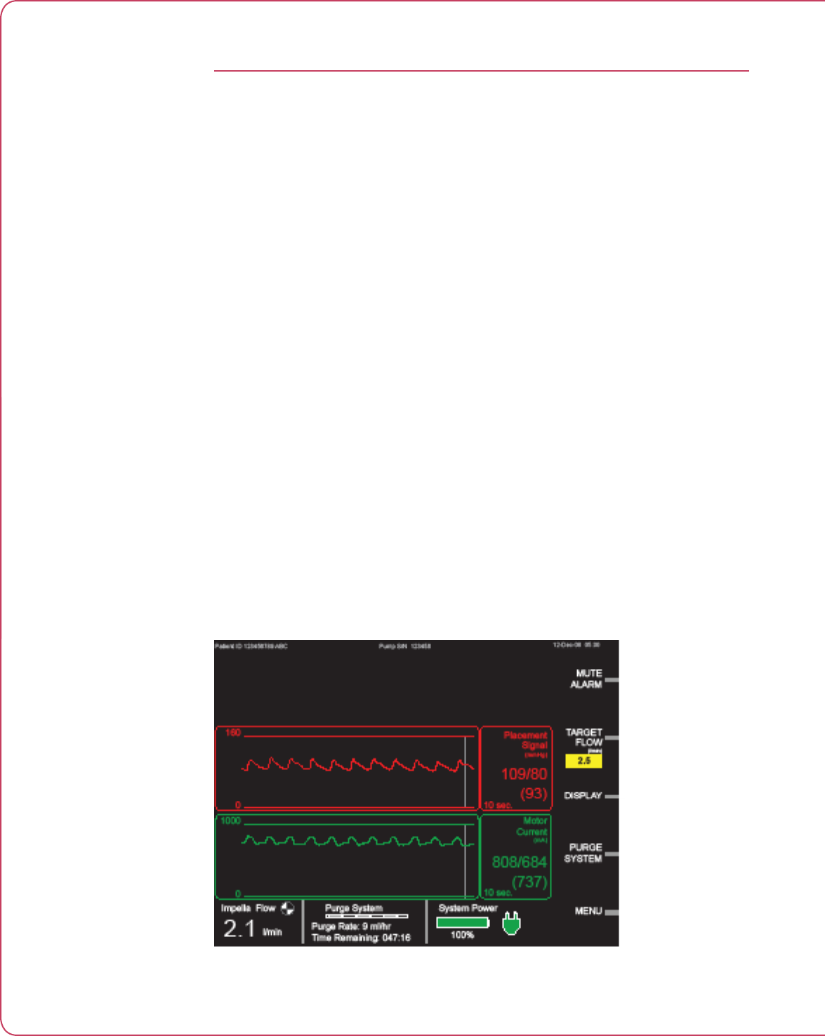
6.6 Instructions for Use
UNDERSTANDING AND MANAGING IMPELLA® POSITION
ALARMS
The Impella® Controller continuously monitors the catheter based on the placement signal and
the motor current.
• Placement Signal:
Is the signal characteristic of aortic or ventricular pressure?
• Motor Current:
Is the signal “pulsatile” or “attened”?
If the system alarms with one of the positioning alarms described below, fluoroscopic imaging is
the best method for conrming position. You can also use TEE or a standard chest X-ray.
If the Impella® is either partly (just the pigtail) or completely in the ventricle, reposition the device
under imaging guidance. If guidance is not available, use the repositioning guide to reestablish
proper placement. (The repositioning guide is discussed later in this section.)
If the Impella® is completely out of the ventricle, do not attempt to reposition the device across
the valve without a guidewire.
The following pages describe possible placement conditions and the associated signal
characteristics and alarm messages as well as actions to take for each.
CORRECT POSITION
If the Impella® 2.5 Catheter is in the correct position, the waveform screen will appear as shown
in Figure 6.1.
Figure 6.1 Correct Catheter Position
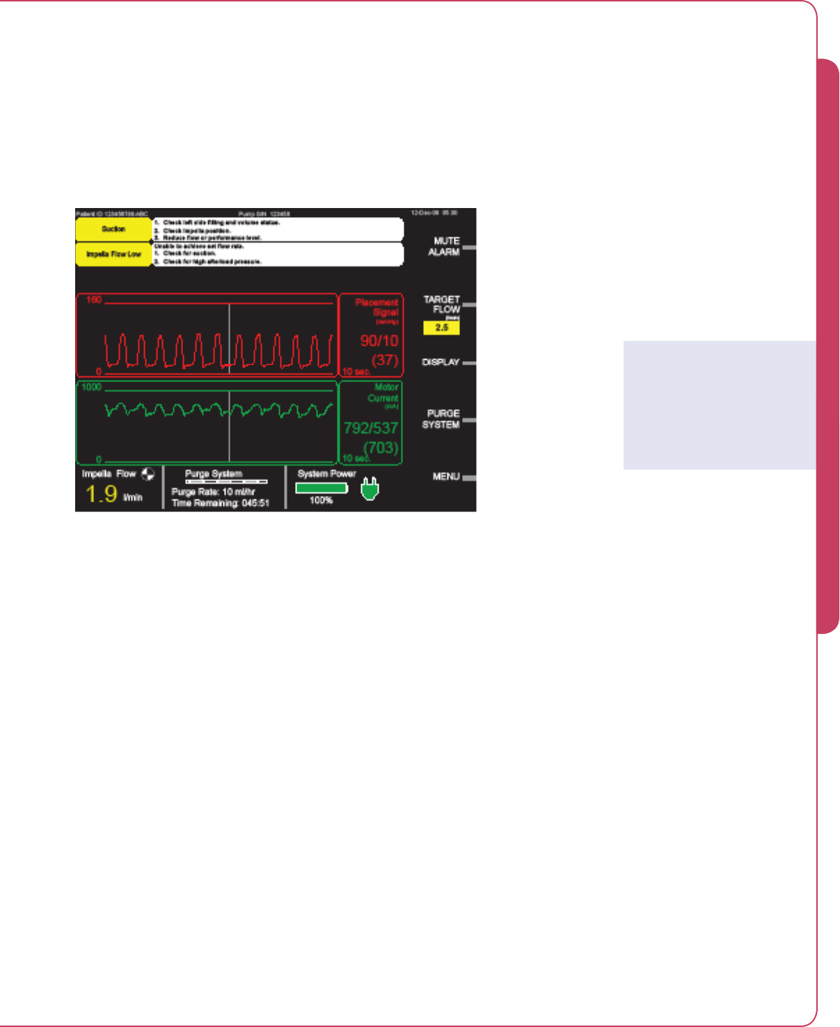
6.7
Impella® Controller with Impella® 2.5
IMPELLA® FULLY IN VENTRICLE
If the Impella® 2.5 Catheter is fully in the ventricle, the following alarm will appear:
Pump Position Wrong
In this situation, the waveform screen will appear as shown in Figure 6.2.
Figure 6.2 Catheter Fully in Ventricle
Actions to take:
1. Under fluoroscopic guidance, if available, reduce the flow rate to 0.5 L/min and
carefully pull back the Impella® Catheter until the aortic waveform signal is showing.
2. When you see the aortic waveform signal, pull the catheter back an additional 4 cm.
Repositioning Guide
The repositioning guide can
also be used for correcting
Impella® positioning.
6 PATIENT MANAGEMENT TOPICS
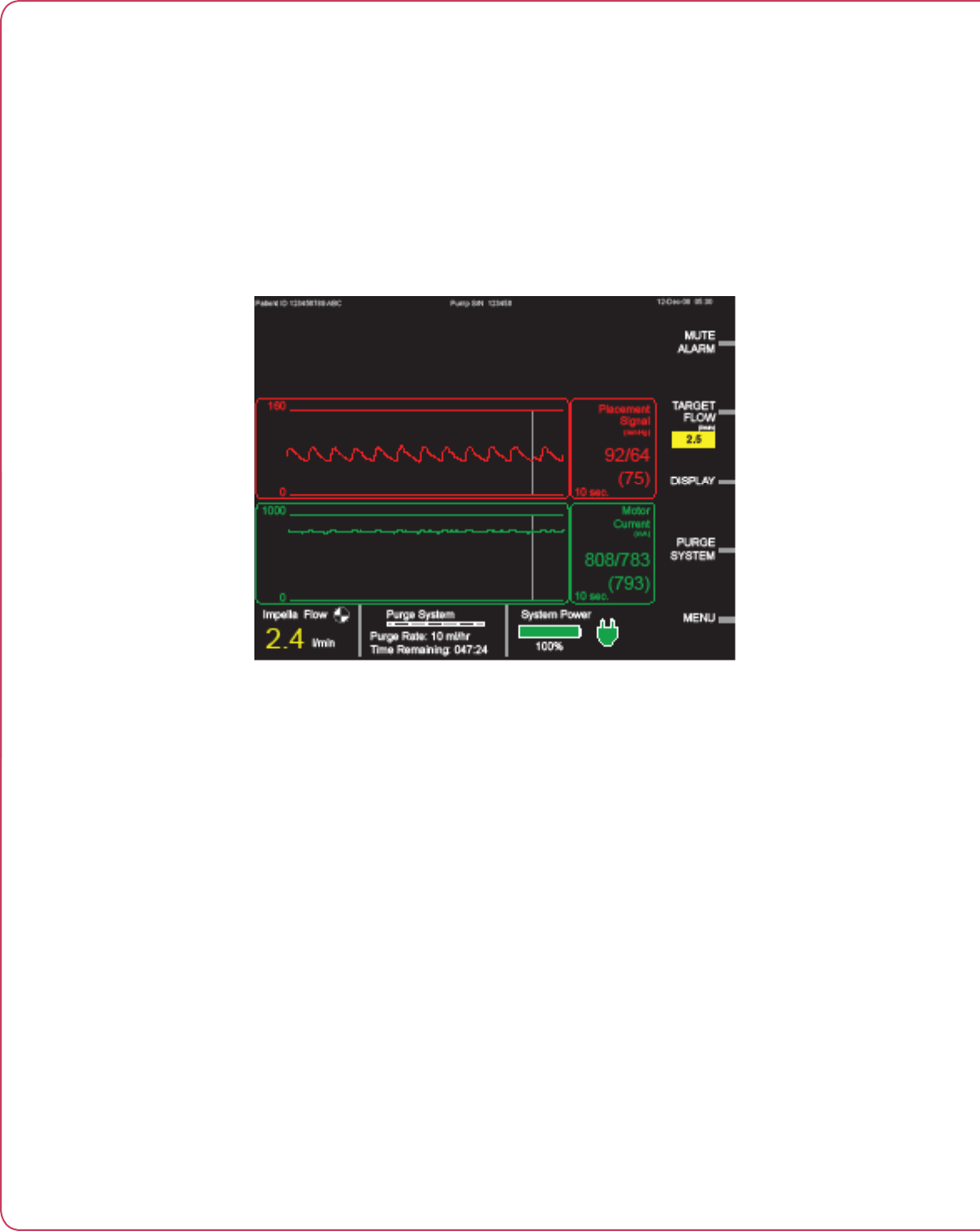
6.8 Instructions for Use
IMPELLA® COMPLETELY IN THE AORTA or INLET AND OUTLET AREA
IN VENTRICLE AND PRESSURE PORT IN AORTA
If the Impella® 2.5 Catheter is completely in the aorta or if the inlet and outlet areas are in the
ventricle and the pressure port is in the aorta, the following alarm will appear:
Pump Position Wrong
In this situation, the waveform screen will appear as shown in Figure 6.3.
Figure 6.3 Impella® Completely in the Aorta or Inlet and Outlet Area
in Ventricle and Pressure Port in Aorta
Actions to take:
1. Under fluoroscopic guidance, determine the pump position.
2. Reduce flow rate to 0.5 L/min and reposition the pump as necessary.
3. If fluoroscopic imaging is not available, reposition the pump according to the
repositioning guide.
4. If step 3 does not provide correct positioning, check the pump position by imaging
methods (fluoroscopy, TEE, or chest x-ray).
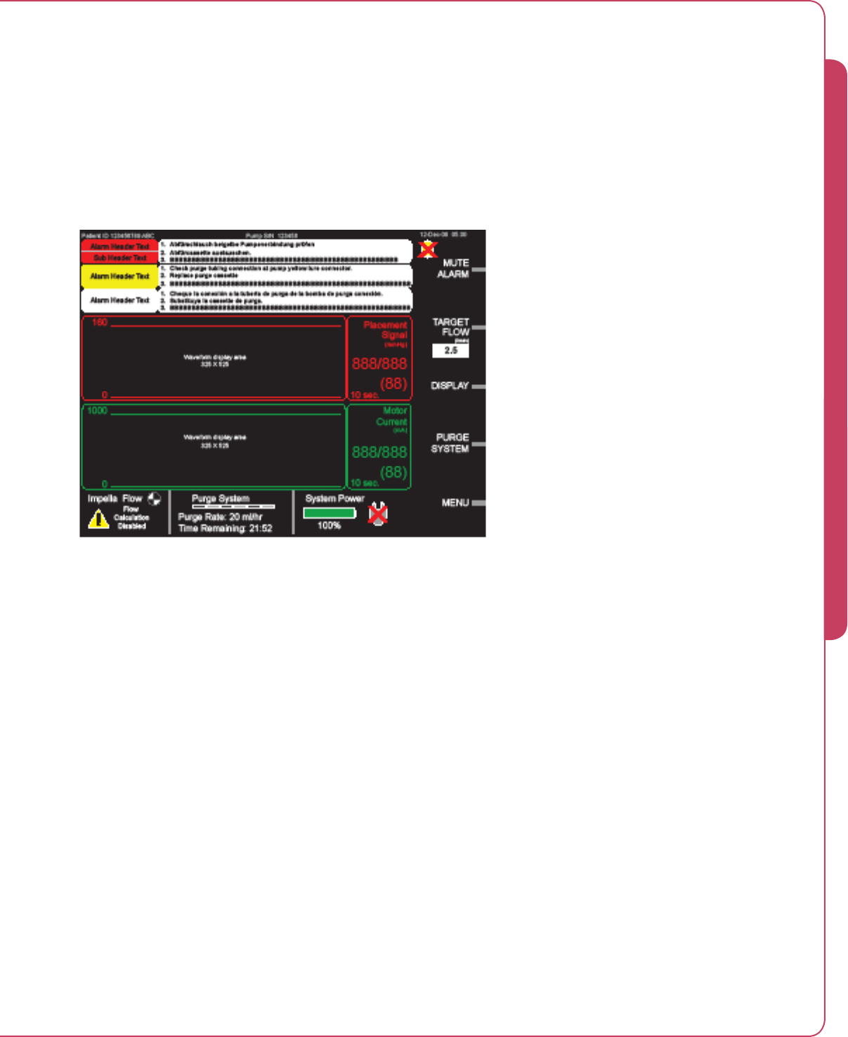
6.9
Impella® Controller with Impella® 2.5
LOW NATIVE HEART PULSATILITY
In a situation of low native heart pulsatility, the Impella® Controller may not be able to
determine the pump position. You may see the following alarm:
Pump position unknown due to low pulsatility.
In this situation, the waveform screen will appear as shown in Figure 6.4.
Figure 6.4 Pump Position Unknown Due to Low Pulsatility
[Waveform TBD; Motor Current y-axis scale to be revised]
Actions to take:
1. Assess cardiac function.
6 PATIENT MANAGEMENT TOPICS
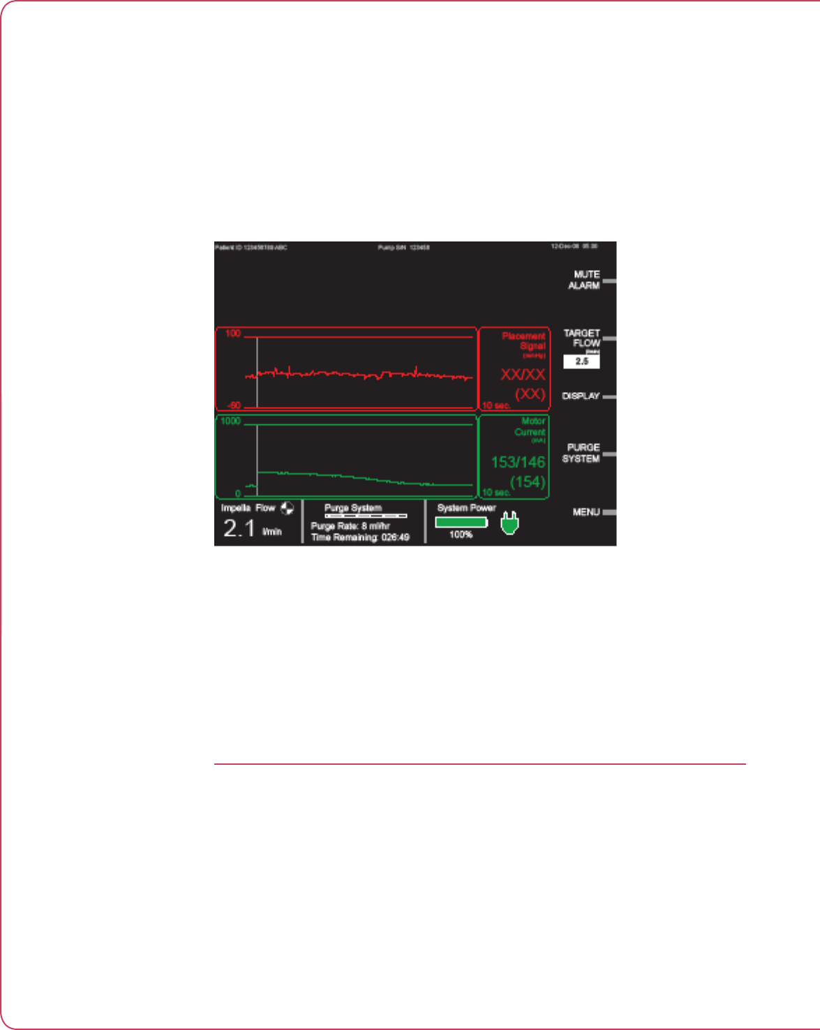
6.10 Instructions for Use
IMPELLA® OUTLET AREA ON OR NEAR AORTIC VALVE
If the Impella® 2.5 Catheter outlet area is on or near the aortic valve, the pump may be too deep
in the ventricle. The following alarm will appear:
Impella Outflow Blocked
In this situation, the waveform screen will appear as shown in Figure 6.5.
Figure 6.5 Impella® Outlet Area on or near Aortic Valve
Actions to take:
1. Assess and adjust pump position under fluoroscopic guidance, if available.
2. If fluoroscopic guidance is not available, reduce the flow rate to 0.5 L/min and gently
pull the catheter back 2 cm and see if the condition resolves.
REPOSITIONING GUIDE
Abiomed strongly recommends using fluoroscopy to guide placement and positioning of the
Impella® Circulatory Support device. However, if fluoroscopy or other imaging guidance is not
available, you can use the repositioning guide to correct the position of the Impella® pump
across the aortic valve. The repositioning guide provides information about the current position
of the Impella® pump and the actions required to reposition the pump.
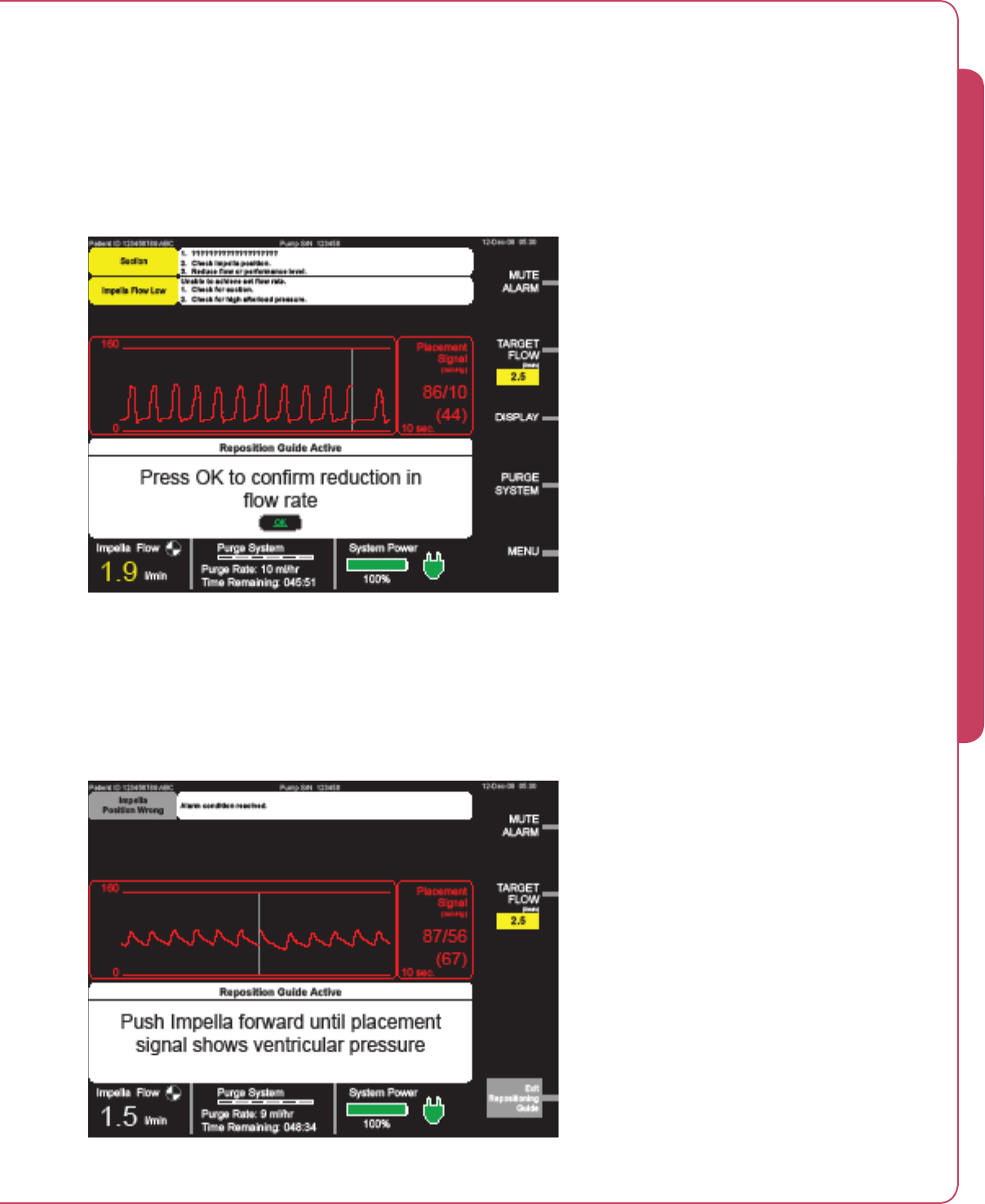
6.11
Impella® Controller with Impella® 2.5
To use the repositioning guide:
1. Press MENU and scroll to “Start Repositioning Guide.” Press the selector knob to
initiation the repositioning guide algorithm.
Figure 6.6 shows the first screen of the repositioning guide. Follow the instructions in
the white instructional display area under the headline “Repositioning Guide Active”.
Figure 6.6 First Repositioning Guide Screen
2. Press OK to confirm reduction in flow rate. The system will reduce flow rate to 1 L/min.
3. Push the Impella® pump forward until the placement signal shows ventricular pressure
(see Figure 6.7).
Figure 6.7 Second Repositioning Guide Screen
6 PATIENT MANAGEMENT TOPICS
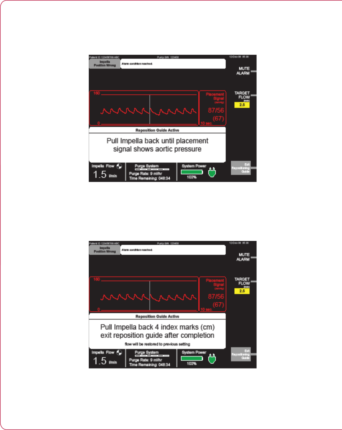
6.12 Instructions for Use
4. Pull the Impella® pump back until the placement signal shows aortic pressure
(see figure 6.8).
Figure 6.8 Third Repositioning Guide Screen
5. Pull the Impella® pump back 4 marks on the catheter. Each mark equals 1 centimeter.
6. Exit the Repositioning Guide using the Exit Repositioning Guide soft button (see
Figure 6.9). When you exit, the controller returns to the original flow rate level.
Figure 6.9 Exit Repositioning Guide Screen
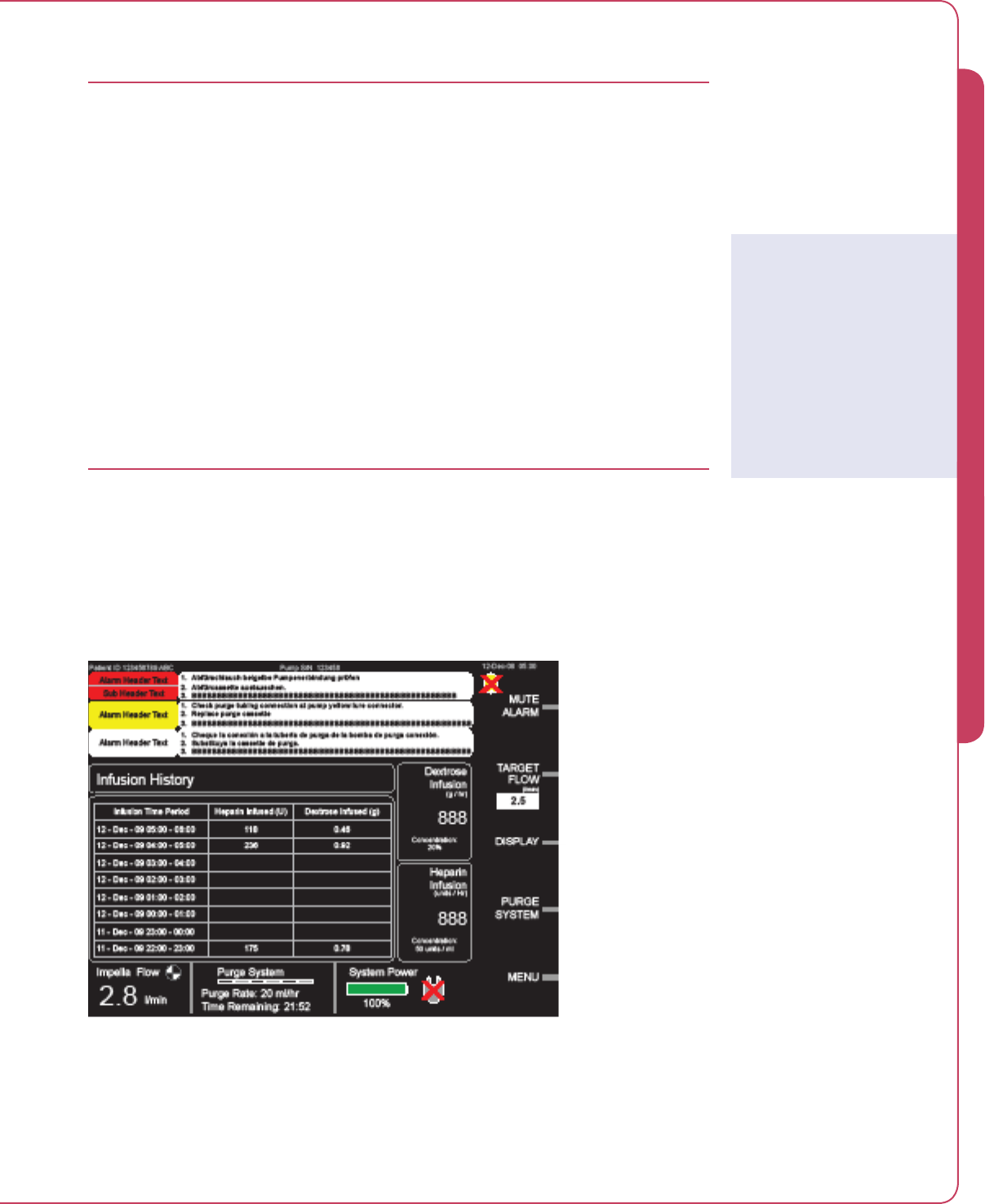
6.13
Impella® Controller with Impella® 2.5
DATA SNAP SHOT RECORDING
The Impella® Controller can save real-time operating data for later analysis using the Data Snap
Shot feature. Data Snap Shot is automatically turned on during certain alarm conditions to
capture data for analysis. The user can also manually turn on the feature at any time to capture
data for later analysis.
To manually access the Data Snap Shot feature:
1. Press MENU and scroll to “Data Snap Shot”. Press the selector knob.
2. The controller records data for a predefined period of 10 minutes. To stop recording
data before the 10-minute time-out, select “Stop Data Snapshot” from the MENU.
INFUSION HISTORY
The Impella® Controller has an Infusion History screen that displays the amount of heparin and
dextrose infused each hour. The calculations begin when the case start procedure is completed
and flow rate is greater than 0. The system stores at least 8 hours of data. Figure 6.10 shows a
sample Infusion History screen.
Figure 6.10 Infusion History Screen
As you can see, the current time period is displayed at the top of the list. This entry provides the
heparin and dextrose infusion rates from the top of the current hour to the current time.
Saving Snap Shot Data
If you select “Start Data Snap
Shot” while the controller is
already saving snap shot data,
the controller will start saving
data to a different snap shot
file. Note: Old data will be
overwritten by new data if the
snap shot data memory is full.
6 PATIENT MANAGEMENT TOPICS

6.14 Instructions for Use
OPERATING THE IMPELLA® 2.5 WITHOUT HEPARIN IN
THE PURGE SOLUTION
The Impella® 2.5 is designed to be operated with a purge solution that contains heparin.
Operation of the system without heparin in the purge solution has not been tested. In the
event that a patient is intolerant to heparin, due to heparin-induced thrombocytopenia (HIT) or
bleeding, physicians should use their clinical judgment in assessing the risks versus benefits of
operating the Impella® System without heparin.
If it is in the best interest of the patient to operate the system without heparin, the dextrose
solution is still required, and physicians should consider an alternative anticoagulant delivered
systemically.
Do not add any alternative anticoagulant (such as a direct thrombin inhibitor) to the purge
solution. The Impella® 2.5 has not been tested with any alternative anticoagulants present
in the purge solution.
GUIDELINES FOR EXPLANT
Patients being supported with the Impella® 2.5 System should be evaluated for explant on a
regular basis.
To evaluate patients for explant, reduce the Impella® 2.5 flow rate and look for the following
signs of native heart recovery:
• AO and CVP pressure remain stable
• Native ejections are visible on the patient pressure monitor
• Native ejections increase after volume loading challenge
• Echocardiography reveals pronounced aortic valve opening
If physicians see these signs of native heart recovery and the patient has demonstrated stable,
ongoing recovery—including stable organ (eg, liver, kidney, lung) function—the patient should
be considered for explant.
If the patient does not meet the criteria for explant, the patient should remain on Impella® 2.5
support, or be transitioned to a longer term device.

6.15
Impella® Controller with Impella® 2.5
HOW TO CHANGE TO BACKUP CONTROLLER
A backup Impella® Controller should be available at all times when a patient is on support. In
the event that the controller fails, follow the steps below to transition the Impella® pump to the
backup controller.
1. Confirm that the backup controller is powered ON and ready.
2. Transfer the purge cassette and purge solution from the primary controller to the
backup controller.
3. Remove the white Impella® connector cable from the primary controller and plug it into
the pump plug on the front of the backup controller.
4. Once the Impella® pump is connected to the backup controller, the “Quick Start”
message will appear on the screen asking the user to confirm re-starting the Impella®
2.5 at the previously set flow rate.
5. Press OK within 10 seconds to confirm restarting the Impella® 2.5 at the previously set
flow rate.
EMERGENCY SHUTDOWN PROCEDURE
1. Press and hold the black power button for 30 seconds.
2. An “Emergency Shutdown Imminent” alarm will sound at 15 seconds.
3. The controller will shut down after 30 seconds.
NOTE: The Impella® pump will continue running at the last setting.
4. Restart the controller.
6 PATIENT MANAGEMENT TOPICS

CLEANING .................................................................................................... 7.1
Cleaning the Impella® Controller and Connector Cable .................................... 7.1
STORING THE IMPELLA® CONTROLLER ........................................................ 7.1
DISPOSING OF THE PUMP AND ACCESSORIES (EU) ..................................... 7.1
RETURNING AN IMPELLA® PUMP TO ABIOMED (US) ................................... 7.1
7 CLEANING, STORAGE, DISPOSAL,
AND RETURNS

7.1
Impella® Controller with Impella® 2.5
CLEANING
CLEANING THE IMPELLA® CONTROLLER AND CONNECTOR CABLE
• Clean the Impella® Controller keypad and display with 70% isopropyl alcohol, or soap and
water.
• Clean the Impella® Controller housing with mild detergent.
• Do not allow any uids to enter the connector sockets.
• Clean the connector cable with 70% isopropyl alcohol.
STORING THE IMPELLA® CONTROLLER
The Li-Ion batteries must be charged for 10 hours prior to system operation. After
being unplugged, the Impella® Controller will operate for at least 60 minutes after
the batteries have been fully charged.
• Place the Impella® Controller on a horizontal surface to prevent falling.
• Connect the AC power cord to an AC outlet.
• The battery may be destroyed if the Impella® Controller is stored with a depleted battery.
DISPOSING OF THE PUMP AND ACCESSORIES (EU)
The Impella® pump and connector cable are disposable items that must be disposed of in
accordance with hospital regulations for blood contaminated materials.
The Impella® Controller is marked according to Directive 2002/96/EEC. Devices sold within the
EEC can be returned to Abiomed Europe GmbH for correct disposal.
RETURNING AN IMPELLA® PUMP TO ABIOMED (US)
To return an Impella® pump to Abiomed, contact your local Clinical Consultant for an Abiomed-
approved return kit (part number 0046-4000).* The kit includes instructions for returning the
pump to Abiomed.
* Only available in the United States
Storing the Controller
To keep the Impella®
Controller battery charged,
the controller should be
plugged into an AC outlet and
switched to the ON position
when it is stored.
7 CLEANING, STORAGE, DISPOSAL, AND RETURNS

7.2 Instructions for Use

TERMINOLOGY, ABBREVIATIONS, AND SYMBOLS ......................................8.1
8 TERMINOLOGY, ABBREVIATIONS,
AND SYMBOLS

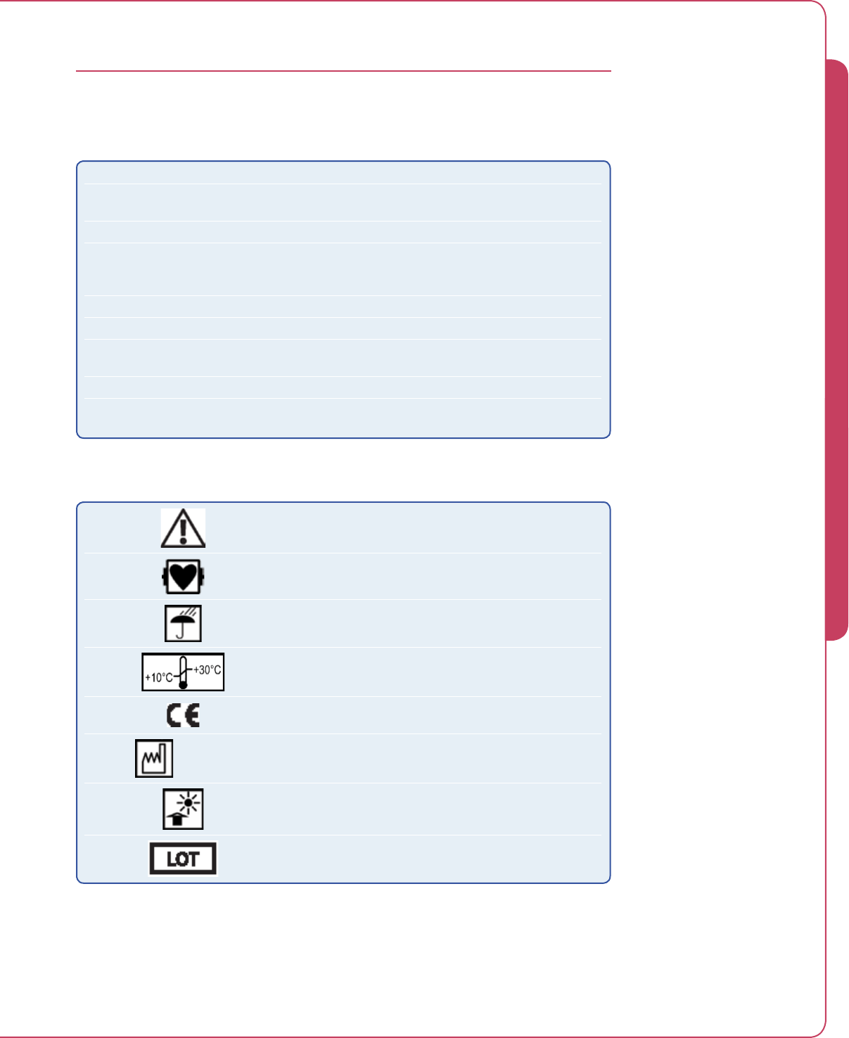
8.1
Impella® Controller with Impella® 2.5
TERMINOLOGY, ABBREVIATIONS, AND SYMBOLS
Table 8.1 Terminology and Abbreviations
Hz Hertz
Pump identification number Identification number of the pump; stated on the package
label and on the display screen
Pump housing Enclosure of the Impella®
Pump
Central delivery unit of the Impella® 2.5, consisting of the
motor, motor housing, pump housing, cannula with inlet and
outlet, and pigtail at the tip
Purge pressure Pressure present in the Impella® 2.5 and in the infusion line
Purge system Impella® purge cassette used for rinsing the Impella® 2.5
Retrograde flow Reverse flow through the intracardiac pump when the pump
is at a standstill (eg, regurgitation)
VVolt
VA Volt ampere (Watt)
Table 8.2 Symbols
Caution; comply with documents (eg, Instructions for Use)
Defibrillator-proof type CF equipment
Keep dry
Storage temperature (eg, 0°C to 30°C)
Declares conformity with directive 93/42/EEC for medical
devices
2009-02 Date of manufacture (eg, February 2009)
Protect from sunlight!
Symbol for lot designation; the manufacturer’s lot
designation must be stated after the LOT symbol
8 TERMINOLOGY, ABBREVIATIONS, AND SYMBOLS
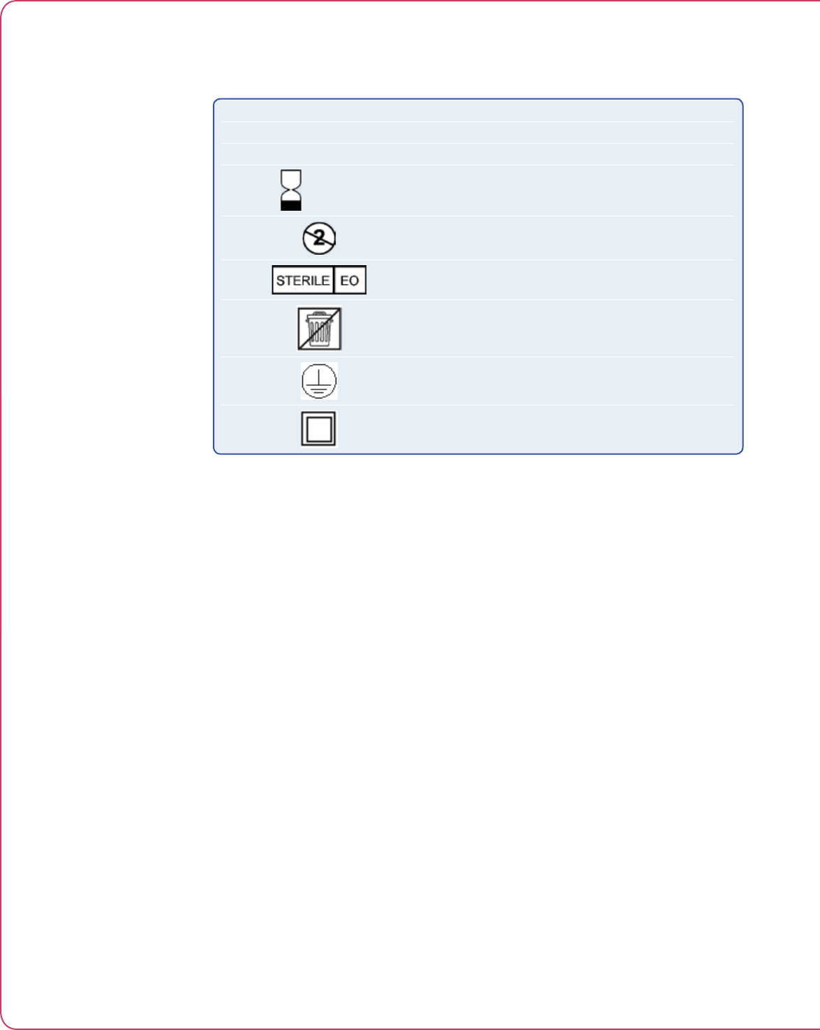
8.2 Instructions for Use
Table 8.2 Symbols (cont’d)
REF 123456 Abiomed part number (eg, part number 123456)
SN 123456 Manufacturer’s serial number (eg, serial number 123456)
Non Sterile! The product is not sterile
2010-06 Use-by date (eg, use before June 2010)
Do not reuse
Sterilized using ethylene oxide
Electric scrap; must be disposed of separately. Must not be
disposed of as domestic waste.
Protective Earth
Protection Class II equipment

IMPELLA® CONTROLLER MECHANICAL ........................................................9.1
IMPELLA® CONTROLLER ELECTRICAL ..........................................................9.1
EQUIPMENT DESIGN ....................................................................................9.2
EQUIPMENT CLASSIFICATIONS ....................................................................9.2
FEDERAL COMMUNICATIONS COMMISSION (FCC) NOTICE ........................9.3
ELECTROMAGNETIC COMPATIBILITY ...........................................................9.3
PATIENT ENVIRONMENT ..............................................................................9.6
WHITE CONNECTOR CABLE ..........................................................................9.8
PUMP PARAMETERS .....................................................................................9.8
IMPELLA® 2.5 DIMENSIONS .........................................................................9.9
9 SYSTEM SPECIFICATIONS


9.1
Impella® Controller with Impella® 2.5
IMPELLA® CONTROLLER MECHANICAL
IMPELLA® CONTROLLER ELECTRICAL
AC operation 100-230 VAC (nominal); 47-63 Hz; 1.1A
Internal battery operation 14.4 VDC (nominal); lithium ion
Characteristic values
Max. power consumption under load
Device fuse
Running time without AC power with fully
charged batteries
120 VA
2x2 A slow-blow
At least 60 minutes (charging duration of at least
10 hours)
Electrical system Installation in accordance with pertinent
regulations is required for use in medical facilities
(eg, VDE 0100, VDE 0107, or ICE stipulations).
Observe country-specific regulations and national
deviations.
Parameter Specification
Temperature Operating: 10°C to 40°C (50°F to 104°F)
Storage: –15°C to 50°C (5°F to 122°F)
Relative Humidity Operating: 95%
Storage: 95%
Atmospheric Pressure Operating: 8000 ft (750 hPa) to –1000 ft (1050 hPa)
Storage: 18,000 ft (500 hPa) to –1000 ft (1050 hPa)
Dimensions Height: 351 mm
Width: 443 mm
Depth: 236 mm
Dimensions –
Packaged
Height: 508 mm
Width: 559 mm
Depth: 406 mm
Weight Maximum: 11.8 kg (26.1 lbs)
Weight – Packaged Maximum: 13.6 kg (30 lbs)
Maintenance and
repair interval
12 months
(Work must be performed by technicians authorized by Abiomed)
9 SYSTEM SPECIFICATIONS

9.2 Instructions for Use
EQUIPMENT DESIGN
The Impella® Controller conforms to the applicable requirements of the following standards:
• UL 60601-1 (2003), 1st Edition
Medical Electrical Equipment, Part 1: General
Requirements for Safety
• CAN/CSA C22.2 No 601.1-M90 (1990; Reafrmed 2005), 2nd Edition
Medical Electrical
Equipment, Part 1: General Requirements for Safety
• EN 60601-1 (1990), 2nd Edition
Medical Electrical Equipment, Part 1: General
Requirements for Safety + A1(93) + A2(95) + A1.3(96)
• IEC 60601-1 (1988), 2nd Edition
Medical Electrical Equipment, Part 1: General
Requirements for Safety + A1(91) + A2(95)
• IEC 60601-1-2 (2001),
Medical Electrical Equipment, Part 1-2: General Requirements for
Safety – Collateral Standard: Electromagnetic Compatibility – Requirements and Tests
• IEC 60601-1-4 (2000), Edition 1.1 Consolidated Edition
Medical Electrical Equipment,
Part 1-4: General Requirements for Safety – Collateral Standard: Programmable Electrical
Medical Systems
• IEC 60601-1-1, (2000/12/01), 2nd Edition
Medical Electrical Equipment, Part 1-1: General
Requirements for Safety – Collateral Standard: Safety Requirements for Medical Electrical
Systems
• IEC 60601-1-8, (2003/08/01), Edition 1
Medical Electrical Equipment, Part 1-8: General
Requirements for Safety – Collateral Standard: General Requirements, Tests and Guidance
for Alarm Systems in Medical Electrical Equipment and Medical Electrical Systems
• IEC 60601-1-6, (2004/06/01), Edition 1
Medical Electrical Equipment, Part 1-6: General
Requirements for Safety – Collateral Standard: Usability
EQUIPMENT CLASSIFICATIONS
Type of protection against electric
shock
IEC 60601-1: Class I degree of protection: CF
defibrillation-proof and internally powered. Relies not
only on basic insulation against shock but also includes
additional protection. Accomplished by providing means
for connecting the equipment to the protective earth
conductor of the fixed wiring of the installation in a way
that prevents
accessible metal parts
from becoming live
if basic insulation
fails
.
Degree of protection against electric
shock for Impella® Controller
Class I Equipment.
Mode of operation Continuous.
Degree of protection against explosion
hazard
Not suitable for use in the presence of a flammable
anesthetic mixture with air or with oxygen or nitrous
oxide. Also not suitable for use in an oxygen-enriched
atmosphere.
Degree of protection against harmful
ingress of water
IEC 60529: IPX1 protected against dripping water.
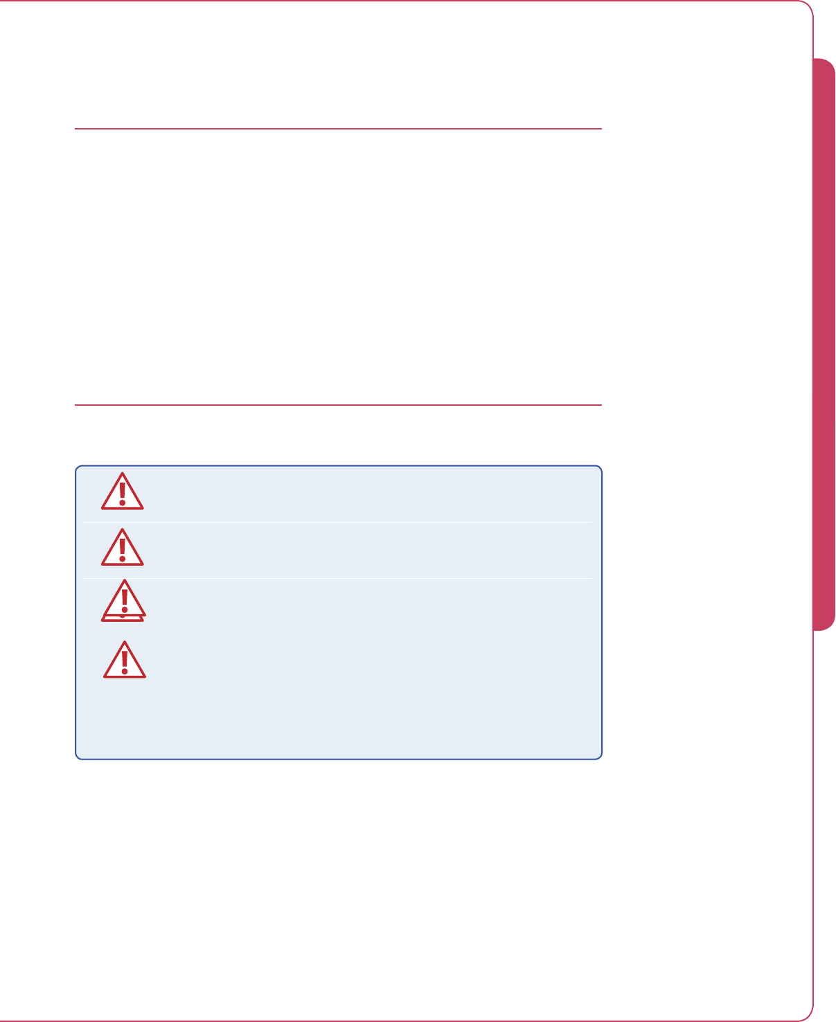
9.3
Impella® Controller with Impella® 2.5
FEDERAL COMMUNICATIONS COMMISSION (FCC) NOTICE
This device complies with Part 15 of the FCC Rules. Operation is subject to the following two
conditions:
1. This device may not cause harmful interference.
2. This device must accept any interference received, including interference that may cause
undesired operation.
Changes or modifications not expressly approved by Abiomed, Inc. could void the user’s
authority to operate this device.
ELECTROMAGNETIC COMPATIBILITY
Medical electrical equipment needs special precautions regarding EMC and needs
to be installed and put into service according to the electromagnetic compatibility
(EMC) information provided in the accompanying documents.
Portable and mobile RF communications equipment can affect medical electrical
equipment.
The equipment or system should not be used adjacent to or stacked with other
equipment. If adjacent or stacked use is necessary, the equipment or system should
be observed to verify normal operation in the configuration in which it will be used.
Use of cables, other than those sold by Abiomed, may result in increased emissions
or decreased immunity of the Impella® Controller.
The Impella® Controller uses RFID (radio frequency identification) to identify and
communicate with the purge cassette. Other equipment may interfere with the
Impella® Controller even if that other equipment complies with CISPR emission
requirements.
NOTE: The EMC tables and other guidelines that are included in this manual provide
information to the customer or user that is essential in determining the suitability of the
equipment or system for the electromagnetic environment of use, and in managing the
electromagnetic environment of use permit the equipment or system to perform to its intended
use without disturbing other equipment and systems or non-medical electrical equipment.
9 SYSTEM SPECIFICATIONS

9.4 Instructions for Use
TABLE 202
Guidance and Manufacturer’s Declaration – Immunity
The Impella® Controller is intended for use in the electromagnetic environment specified below. The
customer or user of the Impella® Controller should ensure that it is used in such an environment.
Immunity Test IEC 60601
Test Level
Compliance
Level
Electromagnetic
Environment –
Guidance
Electrostatic
Discharge (ESD) IEC
61000-4-2
±8 kV contact
±15 kV air
±8 kV contact
±15 kV air
Floors should be wood,
concrete, or ceramic tile. If
floors are synthetic, the relative
humidity should be at least
30%.
Electrical Fast
Transient/burst
IEC 61000-4-4
±2 kV Mains
±1 kV for input/
output lines
±2 kV Mains
±1 kV for input/
output lines
Mains power quality should be
that of a typical commercial or
hospital environment.
Surge
IEC 61000-4-5
±1 kV Differential
±2 kV Common
±1 kV Differential
±2 kV Common
Mains power quality should be
that of a typical commercial or
hospital environment.
Voltage dips, short
interruptions and
voltage variations
on power supply
input lines
IEC 61000-4-11
> 95% dip for 0.5
cycle
60% dip for 5 cycles
30% dip for 25
cycles
> 95% dip for 5
seconds
> 95% dip for 0.5
cycle
60% dip for 5 cycles
30% dip for 25
cycles
> 95% dip for 5
seconds
Mains power quality should be
that of a typical commercial
or hospital environment.
If the user of the Impella®
Controller requires continued
operation during power
mains interruptions, it is
recommended that the
Impella® Controller be powered
from an uninterruptible power
supply or battery.
Power Frequency
50/60Hz Magnetic
Field
IEC 61000-4-8
3 A/m 3 A/m Power frequency magnetic
fields should be that of a
typical location in a typical
commercial or hospital
environment.
TABLE 201
Guidance and Manufacturer’s Declaration – Emissions, All Equipment and Systems
The Impella® Controller is intended for use in the electromagnetic environment specified below.
The customer or user of the Impella® Controller should ensure that it is used in such an environment.
Emissions Test Compliance Electromagnetic Enforcement – Guidance
RF Emissions
CISPR 11
Group 1
Class A
The Impella® Controller uses RF energy only for its
internal function. Therefore, its RF emissions are very
low and are not likely to cause any interference in
nearby electronic equipment.
Harmonics
IEC 61000-3-2
Class A The Impella® Controller is suitable for use in all
establishments, other than domestic and those directly
connected to the public low-voltage power supply
network that supplies buildings used for domestic
purposes.
Flicker
IEC 61000-3-3
Complies

9.5
Impella® Controller with Impella® 2.5
TABLE 203
Guidance and Manufacturer’s Declaration – Emissions,
Equipment and Systems that are Life-Supporting
The Impella® Controller is intended for use in the electromagnetic environment specified
below. The customer or user of the Impella® Controller should ensure that it is used in such an
environment.
Immunity Test IEC 60601
Test Level
Compliance
Level
Electromagnetic
Environment –
Guidance
Conducted RF
IEC 61000-4-6
Radiated RF
IEC 61000-4-3
10 Vrms
150 kHz to 80 MHz
10 V/m
80 MHz to 2.5 GHz
V1 = 10 Vrms
150 kHz to 80 MHz
E1 = 10 V/m
80 MHz to 2.5 GHz
Portable and mobile RF
communications equipment
should be separated from
the Impella® Controller by no
less than the recommended
separation distances
calculated/listed below:
PED )1/5.3(=
PED )1/5.3(=
80 to 800 MHz
PED )1/7(=
800 MHz to 2.5 GHz
Where P is the maximum
power rating in watts and
D is the recommended
separation distance in
meters.
Field strengths from fixed
transmitters, as determined
by an electromagnetic site
survey, should be less than
the compliance levels (V1
and E1).
Interference may occur in
the vicinity of equipment
containing a transmitter.
9 SYSTEM SPECIFICATIONS
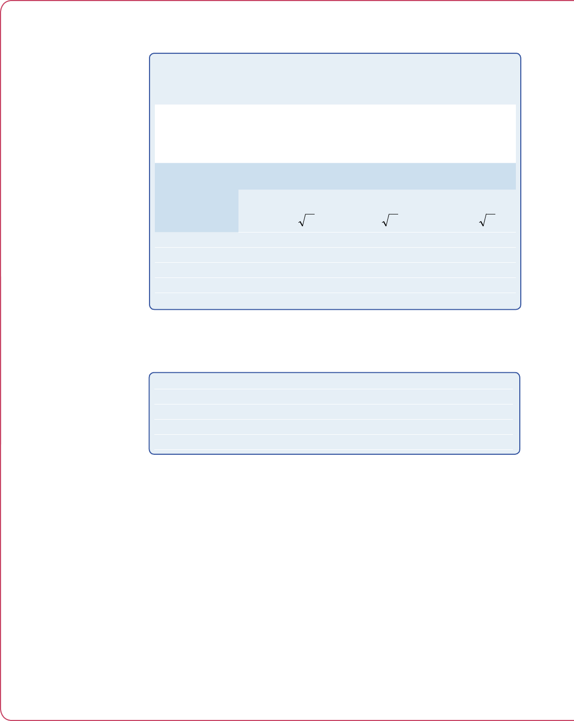
9.6 Instructions for Use
PATIENT
ENVIRONMENT
The Impella® Controller and the
components of the Impella®
Controller System are approved
for use within the patient
environment defined in IEC
60601-1-1 and in the figure
below.
Figure 9.1 Impella®
Controller Patient
Environment
TABLE 205
Recommended Separation Distances Between Portable and Mobile
RF Communications Equipment and the Impella® Controller,
Equipment and Systems that are Life-Supporting
The Impella® Controller is intended for use in the electromagnetic environment in which radiated
disturbances are controlled. The customer or user of the Impella® Controller can help prevent
electromagnetic interference by maintaining a minimum distance between portable and mobile RF
communications equipment and the Impella® Controller as recommended below, according to the
maximum output power of the communications equipment.
Maximum
Output Power
(Watts)
Recommended Separation Distances
for the Impella® Controller (m)
150 KHz to 80 MHz
Pd 3333.2
=
80 to 800 MHz
Pd 3333.2
=
800 MHz to 2.5 GHz
Pd 3333.2
=
0.01 0.11667 0.11667 0.23333
0.1 0.36894 0.36894 0.73785
1 1.1667 1.1667 2.3333
10 3.6894 3.6894 7.3785
100 11.667 11.667 23.333
RFID Transmitter / Receiver Specifications
Frequency 13.56 MHz
Receiver bandwidth TBD
Effective radiated power TBD
Modulation TBD
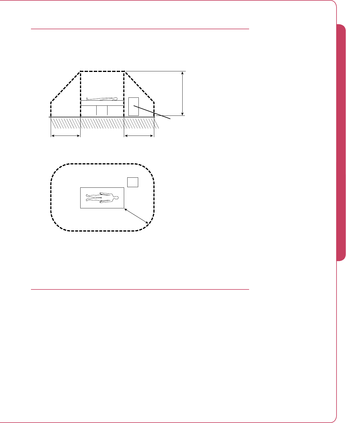
9.7
Impella® Controller with Impella® 2.5
PATIENT ENVIRONMENT
The Impella® Controller and the components of the Impella® Controller System are approved for
use within the patient environment defined in IEC 60601-1-1 and in Figure 9.1 below.
Figure 9.1 Impella® Controller Patient Environment
2.5 m
CONTROLLER
1.5 m
1.5 m
CONTROLLER
9 SYSTEM SPECIFICATIONS

9.8 Instructions for Use
WHITE CONNECTOR CABLE
PUMP PARAMETERS
Length 2.5 m
Service life Single use only
Speed range 0 to 51,000 rpm
Power consumption Less than 0.99 A
Voltage Max. 18 V
Flow-Maximum 2.5 L/min
Purging the Impella® 2.5 Catheter
Recommended purge fluid
Dextrose concentration
Purge pressure
Infusion rate
20% dextrose solution with heparin concentration
of 50 IU per mL
10% to 40%
300 to 1100 mmHg
4 to 20 mL/hr
Maximum duration of use 6 hours (US)
Up to 5 days (EU and Canada)
Dimensions of Impella® 2.5 Catheter
Length of invasive portion (without catheter)
Diameter
130 ± 3 mm
Max. 4.2 mm (nom. 4.0 mm)
Classification per DIN EN 60601-1
European Directive 93/42/EEC
Protection class II, degree of protection:
CF (Impella® Controller and pump)
Classification per MDD/93/42/EEC Class III
Latex free Yes
Latex Free
All versions of the Impella®
Controller and Impella® pump,
including all accessories, are
latex free.
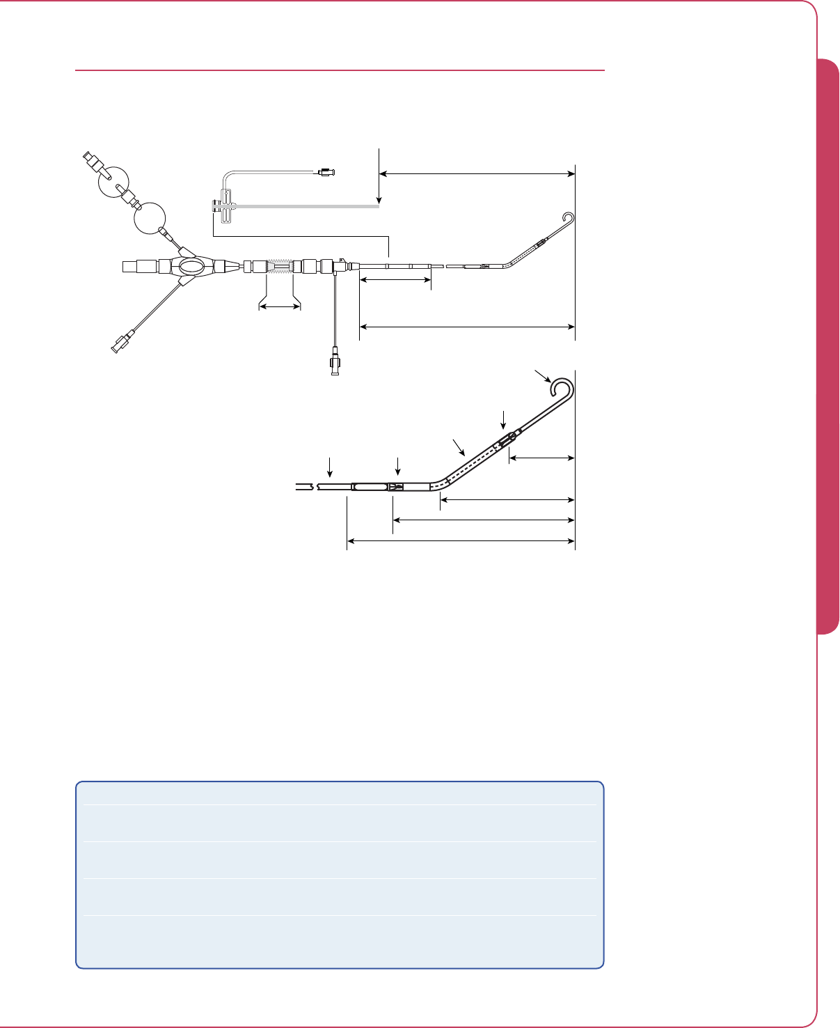
9.9
Impella® Controller with Impella® 2.5
IMPELLA® 2.5 DIMENSIONS
Point of Insertion
Maximum interventional
length
93 cm (min) to 99 cm (max)
116 cm (min) to 122 cm (max)
45.5 cm
Length of
sterile sleeve
11 cm
Repositioning
sheath
13 cm
11 cm
8.5 cm
4.5 cm
9 Fr
12 Fr
6 Fr
Outlet area
Inlet area
Figure 9.2 Impella® 2.5 Dimensions
In a small number of cases (about 2 in every 100 patients) the Impella® 2.5 was not successfully
placed; or it was placed, and the performance was compromised due to patients having
anatomic conditions outside of the range for which the Impella® 2.5 was designed.
The following table describes anatomic conditions that may affect the insertion or operation of
the Impella® 2.5. Physicians should consider these characteristics when evaluating small or very
large patients for Impella® 2.5 support.
Condition Effect
The size and tortuosity of the
femoral and iliac arteries
Limits the ability of the Impella® 2.5 to be advanced from the
insertion site into the left ventricle
Distance from the insertion site
to the apex of the left ventricle
For very tall patients, the maximum interventional length may
not be sufficient to allow correct placement of the Impella® 2.5
Systolic left ventricular (LV) long
axis < 7 cm
The Impella® 2.5 may interfere with the mitral valve
Systolic LV long axis > 11 cm The Impella® 2.5 pigtail will not have a surface to push against
to help stabilize its position, and may have a tendency to swing
or bounce
9 SYSTEM SPECIFICATIONS

9.10 Instructions for Use

IMPELLA® CONTROLLER ALARMS ..............................................................10.1
Alarm Overview ............................................................................................. 10.1
Types of Alarms .............................................................................................10.2
Mute Alarm Function .....................................................................................10.2
Handling Alarms ............................................................................................ 10.3
10 IMPELLA® CONTROLLER ALARMS


10.1
Impella® Controller with Impella® 2.5
IMPELLA® CONTROLLER ALARMS
ALARM OVERVIEW
The Impella® Controller monitors various functions to determine whether its operating
parameters are within expected limits. When a parameter goes outside of allowed limits,
the Impella® Controller displays a message on the display screen and sounds an audible alarm.
When an audible alarm sounds, the operator will need to look at the display screen on the front
of the Impella® Controller to see the text of the message.
The Impella® Controller generates three types of alarms and notifications: critical alarms,
warning alarms, and advisory notifications. Each type has a different audible indicator
(see Table 10.1).
Table 10.1 Audible Alarm and Notification Indicators
Category Audible Indicator*
Critical alarms (high priority) 10 beeps every 6.7 seconds
Warning alarms (medium priority) 3 beeps every 15 seconds
Advisory notifications (low priority) 2 beeps every 30 seconds or no audible sound
* All audible indicators have a sound pressure >80dBA.
The Impella® Controller displays a maximum of three alarm/notification messages at one time.
The critical (red) alarms are displayed first, followed by any warning (yellow) alarms and then
any advisory (white) notifications. If more than one alarm condition is present, the alarm with
the highest priority is displayed first. The message for the highest priority alarm will flash on the
screen.
When an alarm condition occurs, help text is automatically displayed next to the alarm message.
The help text describes the action(s) to take to resolve the alarm.
The system logs the occurrence and the identity of alarms generated. These logs are maintained
when the controller is powered down and after a power failure. The logs are only retrievable by
Abiomed service personnel.
You may look at the Alarm History screen to see a log of the alarms generated and resolved
during a particular case. These logs are not maintained when the controller is powered down or
after a power failure.
Some alarms may be delayed several seconds after the associated event has occurred (see
sidebar). This is due to the logic and/or calculations required to trigger certain alarms.
Alarm Delays
“Impella Defective”
…8 second delay
“ Impella Pump Flow Too High”
…10±1 second delay
“Impella Pump Flow Too Low”
…10±1 second delay
“Impella Position Wrong”
…11±5 second delay
“ Emergency Shutdown
Imminent”
…15±1 second delay
“Battery Failure”
…28±8 second delay
“Battery Communication”
…38±8 second delay
“Purge Flow Low”
…TBD±TBD
“Purge Pressure High”
…TBD±TBD
“Purge System Blocked”
…TBD±TBD
10 IMPELLA® CONTROLLER ALARMS

10.2 Instructions for Use
TYPES OF ALARMS
The Impella® Controller monitors the motor current of the Impella® 2.5. The motor current is
used to calculate the blood flow rate of the Impella® pump. The controller issues an alarm when
the actual flow is more than 0.5 L/min below or above the target flow or if there is suction
within the ventricle. The controller also issues alarms when there is a mechanical or electrical
failure of the pump. The alarm display message provides instructions for either managing the
patient or replacing the Impella®. The alarm continues until the alarm condition is resolved.
The Impella® Controller monitors the pressure generated by a sensor on the Impella® pump. The
pressure is used to determine position across the aortic valve. If the position is wrong or unknown,
the controller issues an alarm with instructions for how to reposition the Impella® pump.
The Impella® Controller monitors the electrical components within the system. If there is a
problem with any of these components, a “Controller Failure” or “Controller Error” alarm occurs.
In the rare event that either of these alarms occur, switch to the backup controller and call
Abiomed service.
The Impella® Controller monitors the purge pressure, flow levels, and fluid remaining in the
system as well as any errors that may occur within the purge system. If air is detected in the
system, an “Air in Purge System” alarm is generated. The alarm prompts you to complete a
de-air procedure to clear the air. Alarms are generated if the pressure does not stay within
300 to 1100 mmHg or flow levels fall outside the range of 2 to 20 mL/hr. Alarms are also
triggered if the purge system is open or blocked, or if the purge flow increases or decreases by
2.5 mL/hr. The purge flow alarm limit is automatically adjusted when you acknowledge the alarm
by pressing the MUTE ALARM button, clearing the alarm. All other alarms continue until the
condition is resolved.
The Impella® Controller monitors the characteristics of the internal batteries. The batteries send
information to the microprocessor in the Impella® Controller. This information is used to calculate
the percentage of power remaining for the system. If the battery percentage falls below the
alarm threshold, an alarm is generated until the system is plugged into an AC power source.
Alarms are also generated if communication with the batteries is lost or if battery temperature
is too high. All of these alarms continue until the condition is resolved.
MUTE ALARM FUNCTION
You can mute alarms by pressing the MUTE ALARM button. This will silence the audible alarm
indicator for 2 minutes. The text of the alarm will remain on the display. By pressing MUTE
ALARM, you are also acknowledging receipt of the alarm. After muting an alarm, if another
alarm occurs it will be displayed, but the sound that occurs will be for the highest priority alarm.
When a condition resolves after you have muted the alarm, the alarm will clear from the screen.
If you do not press the MUTE ALARM button and the condition resolves, a gray alarm is
displayed to inform you that the alarm has been resolved.

10.3
Impella® Controller with Impella® 2.5
HANDLING ALARMS
The following tables list the Impella® Controller alarms from highest to lowest priority, as
indicated by the priority number in the left column. Higher priority alarms override lower priority
alarms. Note that alarm limits cannot be adjusted.
Additional alarms specific to the Impella® 5.0 or LD System are not listed in these tables.
Table 10.2 Critical (Red) Alarms
Priority Alarm Message Action Cause
1Impella Stopped
Controller Failure
1. Replace controller.
2. Restart Impella.
There is a problem with the controller
electronics.
2, 3, 7, 20 Controller Failure* Switch to backup controller. There is a problem with the controller
electronics.
* NOTE: More than one condition
that may trigger this alarm.
4Impella Stopped 1. Restart Impella.
2. Replace Impella after 3rd
unsuccessful restart attempt.
There may be a mechanical or
electrical problem in the Impella
pump.
5Impella Disconnected 1. Check cable connection to
console.
2. Check Impella connection to
cable.
Running pump disconnected.
6Emergency Shutdown
Imminent
Release ON/OFF push button. ON/OFF pressed for 15 seconds but
the Impella pump still connected.
8Battery Temperature High Switch to backup controller. Battery temperature is greater than
60°C.
9Battery Critically Low Plug controller into AC power. Battery power has 15% remaining
capacity.
10 Battery Failure Plug controller into AC power. One of the batteries has failed.
11 Air in Purge System The purge system has stopped.
Follow the instructions in the De-air
Tool to remove the air from the
system.
There is air in the purge line.
12 Purge System Failure Switch to backup controller and
replace purge cassette
There is a problem with the purger
unit driver.
10 IMPELLA® CONTROLLER ALARMS

10.4 Instructions for Use
Priority Alarm Message Action Cause
13 Impella Stopped
Reverse Flow
Restart Impella, or
Remove Impella from ventricle.
Impella is not running, possible
reverse flow through Impella pump.
14 Impella Position Wrong 1. Confirm Impella position with
imaging.
2. Follow repositioning guide if needed.
Wrong placement detection for up
to 14 seconds.
15 Purge Pressure Low 1. Check purge system tubing for leaks.
2. Increase concentration of dextrose in
the purge solution.
Purge pressure has dropped below
300 mmHg with the purge ow ≥
20 mL/hr.
16 Purge Flow Low 1. Check purge system tubing for kinks.
2. Decrease concentration of dextrose in
the purge solution.
Purge pressure is ≥ 1100 mmHg
with the purge flow < 2 mL/hr.
17 Impella Failure Replace Impella. There is a problem with the Impella
pump motor.
18 Impella Motor Current High Replace Impella. There is a problem with the Impella
pump motor.
19 Purge Volume Critically Low 1. Open the PURGE SYSTEM menu
and select Change Purge Fluid.
2. Follow the instructions to change
the purge fluid.
There are 10 mL or fewer remaining
in the purge fluid bag.
21 Purge System Open Check the purge system tubing for open
connections or leaks.
Purge pressure has dropped below
100 mmHg.
22 Purge System Blocked 1. Check all purge system tubing for
kinks or blockages.
2. Decrease concentration of dextrose in
the purge solution.
Purge flow has dropped below 1
mL/hr.
Kinked or blocked purge
connecting tube.
Kinked or blocked purge lumen in
Impella.
23 Purge Line Click-On Not
Detected
Check the purge line click-on and make
sure it is fully inserted.
The controller is not detecting that
the purge pressure transmitter
is clicked into the front of the
controller.
Table 10.2 Critical (Red) Alarms (continued)

10.5
Impella® Controller with Impella® 2.5
Priority Alarm Message Action Cause
24, 37, 41,
42, 44
Controller Error* Switch to backup controller. There is a problem with the
controller electronics.
* NOTE: More than one condition
that may trigger this alarm.
25 Impella Defective Do not use Impella.
Replace Impella.
There is a problem with the Impella
Pump electronics.
26 Impella Position Wrong 1. Confirm Impella position with
imaging.
2. Pull Impella back 2 cm.
3. Follow repositioning guide if
needed.
Wrong placement detection—
Cardiac valve close on pump outlet
openings (within 3 seconds).
27, 28 Suction* 1. Check left side filling and volume
status.
2. Check Impella position.
3. Reduce flow or performance level.
Suction is detected.
* NOTE: More than one condition
that may trigger this alarm.
29 Battery Temperature High 1. Check controller for blocked air
vents.
2. Switch to backup controller.
Battery temperature is greater than
50°C and less than or equal to
60°C.
30 Impella Flow Low Unable to achieve set flow rate.
1. Check for suction.
2. Check for high afterload pressure.
Actual flow is more than 0.5 L/min
below the target flow.
31 Impella Flow High Unable to achieve set flow rate.
Check for low afterload.
Actual flow is more than 0.5 L/min
above the target flow.
34, 35 Impella Sensor Failure
Placement Monitoring is
Suspended*
1. Monitor patient hemodynamics.
2. Monitor Impella position with
imaging.
There is a problem with the Impella
pump sensor signal.
* NOTE: More than one condition
that may trigger this alarm.
38 Purge Volume Low 1. Open PURGE SYSTEM menu and
select Change Purge Fluid.
2. Follow the instructions to change
the purge fluid.
There are 20 mL or fewer remaining
in the purge fluid bag.
39 Battery Level Low Plug the controller into AC power. Battery power has 50% remaining
capacity.
40 Battery Comm. Failure Plug controller into AC power. Loss of communication to the
battery.
43 Purge Cassette Failure Replace purge cassette. There is a problem with the purge
cassette software.
Table 10.3 Warning (Yellow) Alarms
10 IMPELLA® CONTROLLER ALARMS

10.6 Instructions for Use
Priority Alarm Message Action Cause
45 Purge Flow Increased The purge flow has increased by
2.5 mL/hr or more.
This is a notification only; no action is
required.
Purge ow has increased by ≥2.5
mL/hr.
46 Purge Flow Decreased The purge flow has decreased by
2.5 mL/hr or more.
This is a notification only; no action is
required.
Purge ow has decreased by ≥2.5
mL/hr.
47 Mains Disconnected Controller is running on battery power AC Mains was disconnected.
Table 10.4 Advisory (White) Notifications

APPENDIX A: IMPELLA® SYSTEM LIMITED SERVICE WARRANTY .............. A.1
Impella® System Limited Service Warranty (US) ................................................A.1
Impella® System Limited Service Warranty (Europe) ..........................................A.1
APPENDIX B: TECHNICAL SAFETY INSPECTIONS,
MAINTENANCE, AND REPAIR ......................................................................B.1
Technical Safety Inspections ............................................................................ B.1
Maintenance and Repair .................................................................................. B.1
APPENDIX C: ABIOMED-APPROVED GUIDEWIRES ......................................C.1
APPENDIX D: IMPELLA® CONTROLLER MENU STRUCTURE ........................ D.1
Overview .........................................................................................................D.1
MUTE ALARM .................................................................................................D.1
TARGET FLOW .................................................................................................D.1
DISPLAY ..........................................................................................................D.2
PURGE SYSTEM ...............................................................................................D.2
MENU .............................................................................................................D.3
APPENDICES


A.1
Impella® Controller with Impella® 2.5
APPENDIX A: IMPELLA® SYSTEM LIMITED SERVICE
WARRANTY
IMPELLA® SYSTEM LIMITED SERVICE WARRANTY (US)
ABIOMED, Inc. warrants that, at the time of installation, all Impella® Systems (the “Goods”) sold will
be free from defects in material and workmanship and remain free from defects under normal use
and service for a period of one (1) year from the date of installation or title transfer. Extended warranty
and service may, at ABIOMED’s option, be offered for an additional charge, in which event separate or
additional terms and conditions may apply. This warranty provides coverage for the Impella® Controller.
This warranty does not cover routine Preventative Maintenance or replacement parts that are consumed
per the controller's periodic maintenance schedule outlined in the Operator’s and Service Manuals.
The express warranty set forth on this page is the only warranty given by ABIOMED
with respect to any goods furnished hereunder. ABIOMED makes no other warranty,
express, implied or arising by custom or trade usage, and specifically makes no warranty
of merchantability or of fitness for any particular purpose. Said express warranty shall not
be enlarged or otherwise affected by ABIOMED’s rendering of technical or other advice or
service in connection with the Goods.
ABIOMED shall not be liable for incidental or consequential losses, damages or expenses, directly or
indirectly arising from the sale, handling or use of the Goods, or from any other cause relating thereto,
and ABIOMED’s sole responsibility under this warranty will be, at its option, to 1) repair or replace the
Goods or any components of the Goods found to be defective in workmanship or material during the
foregoing warranty period, or 2) to refund the purchase price paid. All replaced components and Goods
will become the property of ABIOMED. This warranty shall not apply if the Goods have been: (a) repaired
or altered in any way by other than ABIOMED or ABIOMED authorized service personnel; (b) subjected
to physical or electrical abuse or misuse; or (c) operated in a manner inconsistent with ABIOMED’s
instructions for use of the Goods. If ABIOMED determines that a claim was not caused by ABIOMED
or ABIOMED’s authorized service personnel, then Buyer shall pay ABIOMED for all related costs incurred
by ABIOMED. This warranty is not transferable without the express written consent of ABIOMED.
Under this warranty, ABIOMED will provide at no charge, updates or modifications which directly affect
the safe operation of the Goods. ABIOMED is not obligated to provide updates or modifications which
provide (a) product improvement or enhancement; (b) new product features, or (c) options to the Goods.
ABIOMED has no obligation to provide a loaner system during service or maintenance of the Goods.
However, at ABIOMED’s sole discretion, ABIOMED may provide such loaner systems.
This warranty applies to the Impella® Controller and not to any disposable or other component of the
Impella® System. Specific items excluded from this warranty include, but are not limited to, pumps,
external tubing, and accessories.
This warranty may not be amended without the express written consent of an authorized officer of
ABIOMED, Inc.
IMPELLA® SYSTEM LIMITED SERVICE WARRANTY (EUROPE)
Please contact your EU representative for warranty information.
APPENDIX A


B.1
Impella® Controller with Impella® 2.5
APPENDIX B: TECHNICAL SAFETY INSPECTIONS,
MAINTENANCE, AND REPAIR
TECHNICAL SAFETY INSPECTIONS
In accordance with the specification issued by Abiomed as per §6 MPBetreibV (German
regulation), the Impella® Controller must be subject to yearly technical safety inspections.
Technical safety inspections may only be carried out by authorized technicians in accordance
with the technical safety inspection requirements presented below and must be documented in
the medical product logbook in accordance with §7 MPBetreibV.
A sticker on the device indicates the date for the next required inspection. Figure B.1 shows
a sticker indicating that inspection is required in May 2010. However, the stipulations in the
medical product logbook are binding in any case.
Figure B.1 Inspection Sticker Showing Inspection Required in May 2010
The following technical safety inspections are required for the Impella® Controller:
• Inspection of labeling and instructions for use
• Visual inspection of the device and its accessories for any signs of damage
• Testing for electrical safety as per DIN VDE 751 or DIN EN 60 601
• Leakage current test
• Dielectric strength test
• Functional testing of all switches, keys, rotary knobs, sockets, and control lights on the device
• Checking battery operation
If defects become apparent during the technical safety inspections that could endanger patients,
employees, or third parties, then the device must not be operated until the defects have been
remedied by proper technical servicing.
MAINTENANCE AND REPAIR
The Impella® Controller is subject to 24-month maintenance and repair intervals. The
corresponding work must be performed by technicians authorized by Abiomed, and must
be documented in the medical product logbook in accordance with §7 MPBetreibV (German
regulation).
APPENDIX B


C.1
Impella® Controller with Impella® 2.5
APPENDIX C: ABIOMED-APPROVED GUIDEWIRES
Use only Abiomed-tested and supplied guidewires with the Impella® 2.5 Catheter. Guidewires
are specifically designed with unique characteristics to optimize performance of the Impella® 2.5
Circulatory Support System. Guidewires and catheters should always be used in accordance with
Abiomed’s instructions.
The following alternative guidewires have been tested and approved for use with the
Impella® 2.5 System:
• Boston Scientic Platinum Plus™ ST 0.018 in
Catalog number 46-605, model ST/0.018/260
• Boston Scientic Platinum Plus™ ST 0.014 in
Catalog number 1752 (H74917520), model ST/.014/300
• Boston Scientic V-18 Control Wire™ ST 0.018 in
Catalog number 46-854, model V18/18/300
• Abbott SteelCore™ 18
Catalog number 1003282
APPENDIX C


D.1
Impella® Controller with Impella® 2.5
APPENDIX D: IMPELLA® CONTROLLER MENU STRUCTURE
OVERVIEW
The soft buttons on the Impella® Controller provide access to the controller menu structure.
The menu structure has 5 main elements:
• MUTE ALARM
• TARGET FLOW
• DISPLAY
• PURGE SYSTEM
• MENU
This Appendix provides an overview of the Impella® Controller menu structure. Many of the
functions accessed through this menu structure are also discussed elsewhere in this manual.
MUTE ALARM
The MUTE ALARM soft button mutes (silences) active alarms. It does not open another menu.
When you press MUTE ALARM, a bell icon with an X through it appears in the upper right
of the display screen. If no alarms are active, no bell icon is displayed. When you press MUTE
ALARM it acknowledges all active alarms and silences the audio for all alarms for 2 minutes
or until another alarm arises. Pressing MUTE ALARM also clears any resolved alarm on the
display. (Refer to Section 10 for more information about Impella® Controller Alarms.)
TARGET FLOW
The TARGET FLOW soft button opens the flow icon enabling you to select the desired flow
rate. The target flow icon is shown in Figure 5.14 in section 5 of this manual and the procedure
for setting flow rate is described in “Positioning and Starting the Impella® 2.5 Catheter” in
section 5.
APPENDIX D

D.2 Instructions for Use
DISPLAY
The DISPLAY soft button opens a menu that includes the following options for viewing
waveforms and navigating to other screen displays:
• Y axis Scale – opens a menu from which you can select a waveform and change its
appearance by adjusting the scale of the y-axis.
Once the waveform is selected, turn the selector knob clockwise to increase the y-axis
scale and counterclockwise to decrease the y-axis scale.
Select OK to accept the new y-axis scale.
Select Restore to return to the default y-axis scale.
Select Initial to set the y-axis to the previously set scale.
Select Center Signal to center the waveform.
Select Cancel to exit the tool.
• Time Scale – allows you to apply different time scales to the currently displayed
waveforms. The time scale options for the placement signal and motor current waveforms
are 10 seconds, 5 minutes, and 5 hours. For the purge screen, the options are 1 hour,
8 hours, and 12 hours.
• Center – automatically centers the motor current waveform and adjusts the range
accordingly.
• Infusion – opens the Infusion History screen. The Infusion History screen, which is
discussed in “Infusion History” in section 6 of this manual, shows the amount of heparin
and dextrose delivered for the past 8 hours or longer, if applicable. The top entry in the
table shows the amount of heparin and dextrose infused from the top of the hour through
the current time. (See Figure 6.10 in section 6.)
• Purge – displays the purge system waveforms and pressure and flow values.
• Placement – opens the placement signal / motor current waveform screen
(shown in Figure 4.3 and described in section 4 under “Impella® Controller Waveform
Screen Display”).
• Home – opens the home screen (shown in Figure 4.2 and described in section 4 under
“Impella® Controller Waveform Home Screen Display”).
PURGE SYSTEM
The PURGE SYSTEM soft button opens a menu that includes the following purger procedure
options:
• Change Purge Fluid – starts the procedure to change the purge fluid
• Change Purge Cassette – starts the procedure to change the purge cassette
• Change Purge System – starts the procedure to change both the purge fluid
and purge cassette
• De-air Purge System – starts the de-air procedure
These procedures are described in section 6 under “Purger Procedures.”

D.3
Impella® Controller with Impella® 2.5
MENU
The MENU soft button opens a menu of options related to controller settings, alarm history,
repositioning, and starting a procedure. The menu includes the following options:
• Settings / Service – allows you to set the current time zone, set screen brightness, view
error history, or select the language for the system displays.
Time Zone. Opens the Time Zone selection box. Turn the selector knob clockwise to
scroll down the list of selections and counterclockwise to scroll up the list. Press the
knob to make your selection and the new time zone is immediately displayed on the
controller.
Screen Brightness. Opens the Screen Brightness selection box. The brightness
of the screen display can be set from 50% to 100%. Select OK to confirm selection.
Select Cancel to cancel selection.
Language. Opens the Language selection box. Use the selector knob to select
German, English, French, Italian, Spanish, or Dutch. The system will immediately
change the language on the controller for all displayed text. This language will be
used after system restart unless another language is selected.
• Alarm History – opens the Alarm History table. This provides a visual display of the
chronology of stored alarm messages. The most recently occurring alarm message is
displayed at the top of the list. For each message, the date and time it occurred and the
alarm message heading is displayed. You can use the selector knob to select individual
alarm messages and an explanation for the selected alarm message will be displayed in
the Failure Description Box. Press EXIT to exit the Alarm History analysis.
• Data Snap Shot – starts the Data Snap Shot function to save real-time operating data
for later analysis. Data Snap Shot is described under “Data Snap Shot” in section 6
of this manual.
• Start Repositioning Guide – opens the repositioning guide, which provides
information about the current position of the Impella® pump and the actions required
to reposition the pump. The repositioning guide is described under “Repositioning Guide”
in section 6 of this manual.
• Case Start – begins the case procedure. Case Start is described in Section 5 under
“Case Start.”
APPENDIX D

Abiomed, Inc.
22 Cherry Hill Drive
Danvers, Massachusetts 01923 USA
Voice: 978-777-5410
Facsimile: 978-777-8411
Email: clinical@abiomed.com
Abiomed Europe GmbH
Neuenhofer Weg 3
52074 Aachen, Germany
Voice: +49 (241) 8860-0
Facsimile: +49 (241) 8860-111
Email: europe@abiomed.com
Clinical support 24 hours per day, 7 days a week:
1-800-422-8666 (US)
+49 (0) 1805 2246633 (EU)
www.abiomed.com