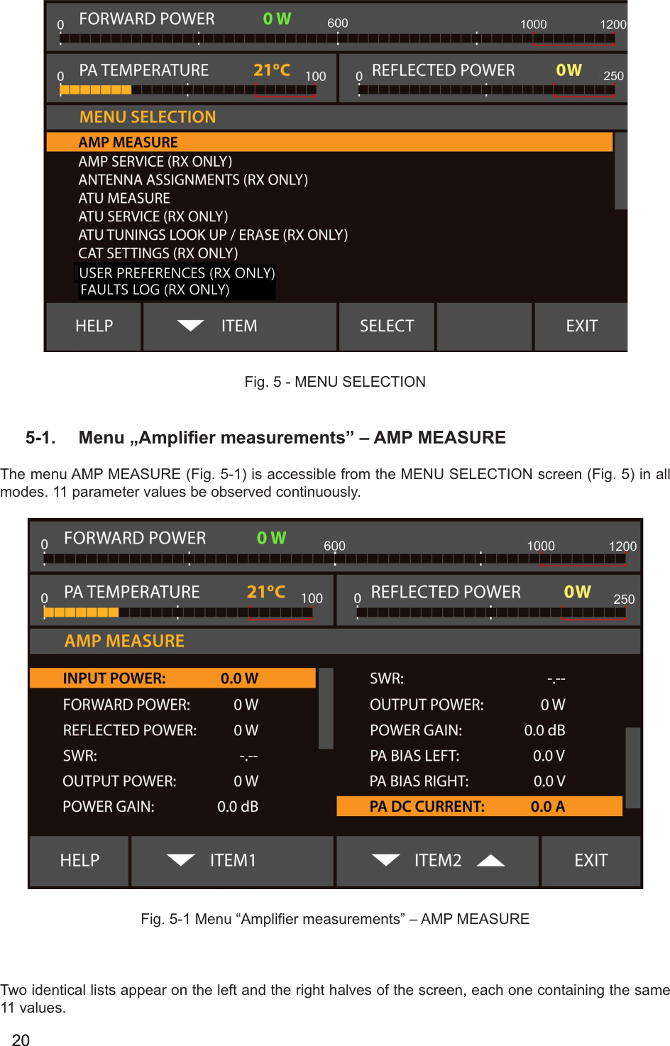
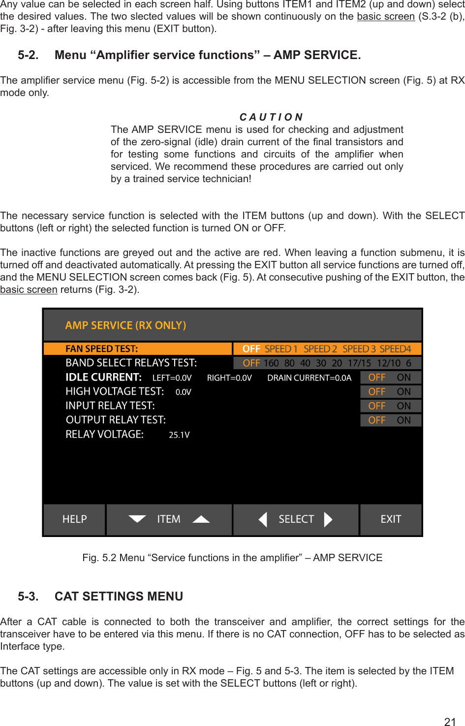
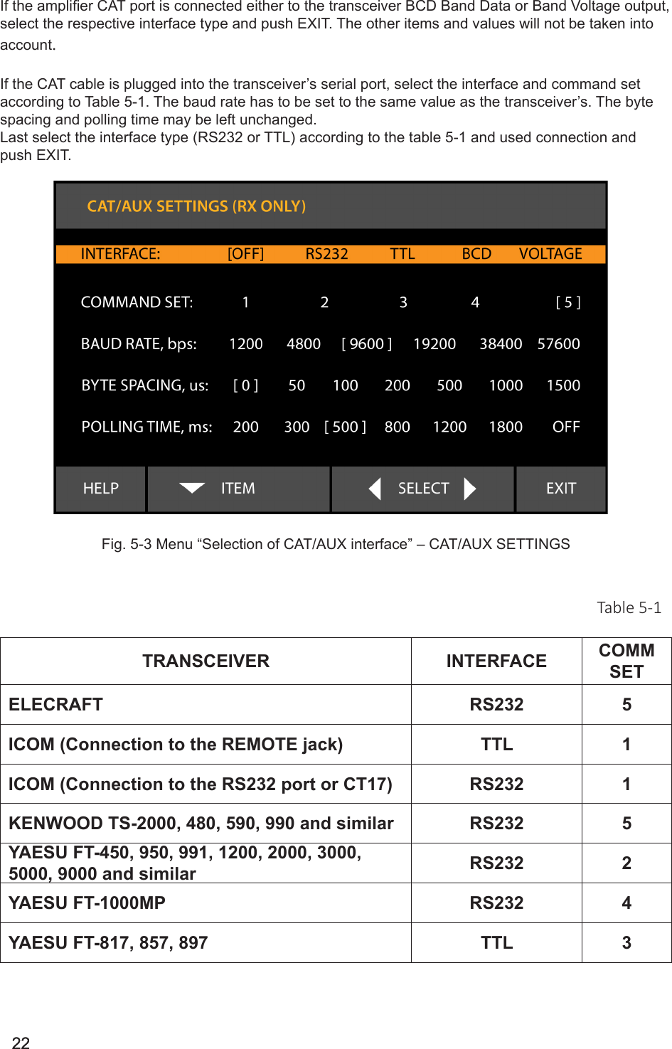
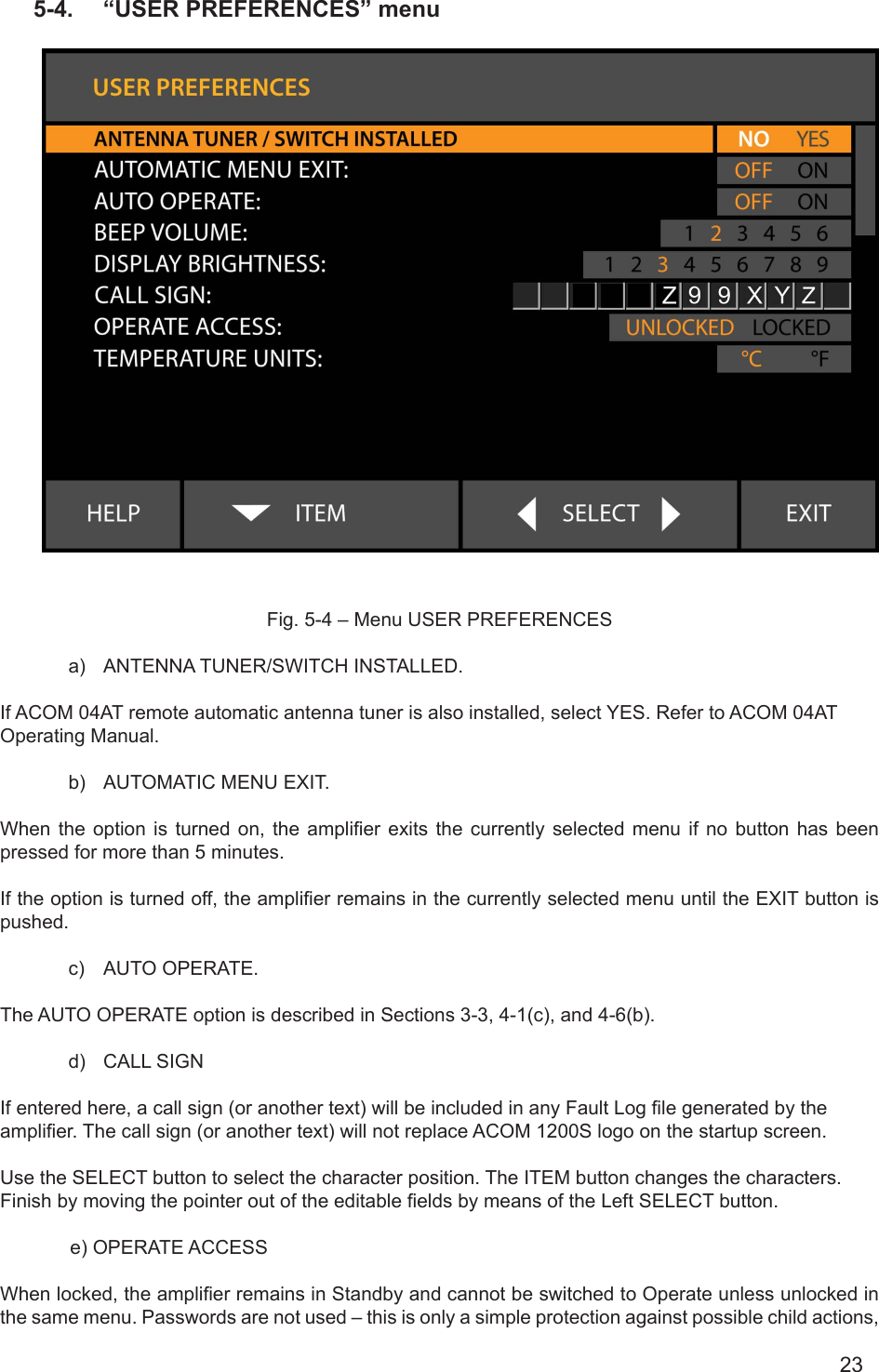
Acom 1200S HF+6m Linear Amplifier User Manual
ACOM Ltd HF+6m Linear Amplifier Users Manual
UserManual.wiki
>
Acom
>
1200S User Manual
Users Manual
Navigation menu
Upload a User Manual
Namespaces
Wiki Guide
HTML
PDF
Info
Views
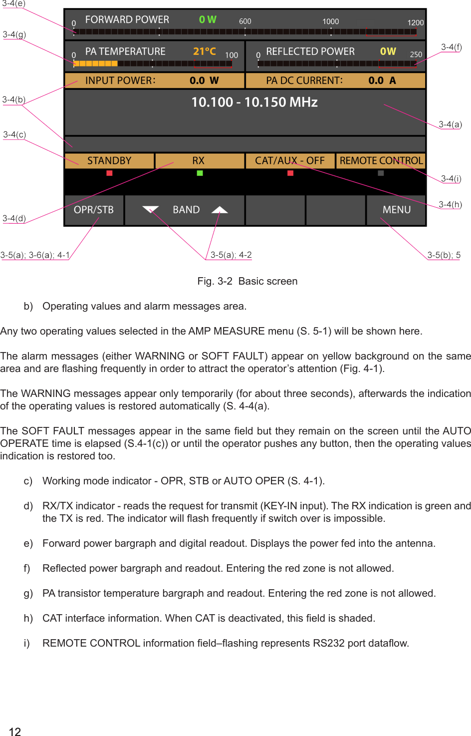
User Manual
Discussion / Help
Navigation