Users Manual

Exhibit 6: User’s Manual
External Radio Frequency
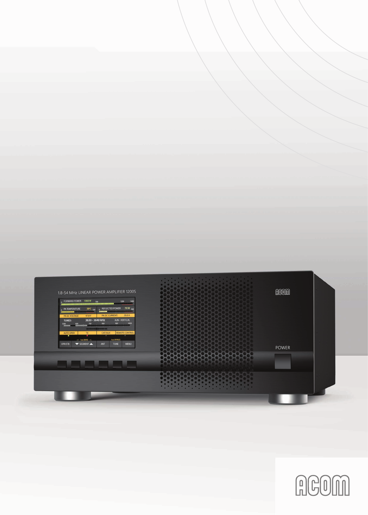
Power Amplifier ACOM 1200S
Model 1200S
Outstanding HF Power Products
HF + 6 m SOLID STATE LINEAR AMPLIFIER
ACOM1200S
OPERATING MANUAL
1
TABLE OF CONTENTS
1. GENERAL INFORMATION .........................................................................................................................3
1-1. Inroduction and description .......................................................................................................3
1-2. Owner assistance .....................................................................................................................3
1-3. Equipment supplied and options ...............................................................................................3
1-4. Features .................................................................................................................................... 4
1-5. Safety considerations, explicit denitions .................................................................................4
2. INSTALLATION ........................................................................................................................................... 5
2-1. Unpacking and Initial Inspection ...............................................................................................5
2-2. Amplier operating location selection; cooling. ......................................................................... 6
2-3. Connecting the amplier within the shack ................................................................................6
2-4. Installing options and connecting to external devices, computer, etc. ......................................9
3. POWERING AND OPERATION ................................................................................................................10
3-1. Low energy stand-by mode of the power supply ....................................................................10
3-2. Front panel - controls and indication .......................................................................................10
3-3. Initial turning on ...................................................................................................................... 11
3-4. Basic screen ........................................................................................................................... 11
3-5. Control system – buttons and menus .....................................................................................13
3-6. Test transmission ....................................................................................................................13
4. AMPLIFIER OPERATION .........................................................................................................................16
4-1. Change of modes, RX / TX and Operate / Stand-by; option AUTO OPERATE ......................16
4-2. Band change, standard and expanded frequency coverage ..................................................17
4-3. Operation with an external antenna tuner ...............................................................................18
4-4. Automatic protection system ................................................................................................... 18
5. MENUS – SETTINGS AND OPTIONS .....................................................................................................19
5-1. Menu “Measurements in the amplier” – AMP MEASURE .....................................................20
5-2. Menu “Service functions in the amplier” – AMP SERVICE. ..................................................21
5-3. Menu CAT/AUX SETTINGS....................................................................................................21
5-4. Menu “USER PREFERENCES” .............................................................................................23
5-5. FAULTS LOG ..........................................................................................................................24
5-6. RESTORE DEFAULT SETTINGS ........................................................................................... 24
6. REMOTE CONTROL ................................................................................................................................25
6-1. General information ................................................................................................................25
7. MAINTENANCE ........................................................................................................................................ 25
7-1. Periodic maintenance; general checks and cleaning ..............................................................25
7-2. Replacement of fuses .............................................................................................................27
7-3. Using the fault codes (signatures) for diagnostics ..................................................................27
7-4. FIRMWARE UPDATES ...........................................................................................................28
8. SPECIFICATIONS ....................................................................................................................................28
8-1. Parameters .............................................................................................................................28
8-2. Functions ................................................................................................................................29
8-3. Storage and shipment ............................................................................................................. 29
9. DISCLAIMER ............................................................................................................................................30
22
3
1. GENERAL INFORMATION
1-1. Inroduction and description
This manual describes the installation, operation, and maintenance of the HF+6m solid-state linear
power amplier ACOM 1200S.
ACOM 1200S is a state-of-the art linear amplier, covering the amateur bands from 1.8 to 54MHz with
1000W output power (PEP or continuous carrier) with less than 50W of drive. The amplier operating
information is shown on a multi-functional, high resolution color display. ACOM 1200S may by controlled
either by the six front panel buttons or remotely – by an RS232 port.
NOTE
ACOM 1200S is designed to work with ACOM 04AT
Remote Automatic Antenna Tuner. The connection of ACOM
04AT will make accessible the features that are inactive on
the amplier display when ACOM 1200S operates without
ACOM 04AT. The operation of ACOM 1200S with ACOM
04AT is described in the ACOM 04AT Operation Manual.
1-2. Owner assistance
If technical or operating assistance is needed, please contact your local dealer rst. In the unlikely
case of you needing further information, you may get in touch with ACOM via: fax (+ 359 2 920 96 56),
telephone (+359 2 9209780), e-mail (acom@acom-bg.com, acom@mail.orbitel.bg) or by post (blvd.
Nikola Mushanov 151, 1330 Soa, Bulgaria). Website: www.acom-bg.com.
1-3. Equipment supplied and options
The amplier is supplied in a single box including:
- the amplier ACOM 1200S;
- a power cord;
- this manual with a CE declaration of compliance;
- four pieces of spare fuses: 2x6.3A/250V for operation on 200-240VAC mains and 2x10A/250V
for operation on 100-120VAC mains.
1-4. Features
• 5“ high resolution color display (108x65mm), 800x480 pixels, and 24-bit color.
• The nal PA stage uses a rugged LDMOS transistor - BLF188XR.
• Compatible with all transceiver models available on the market - does not need any special
signals: „ground on transmit“ and less than 50W of RF drive power is sufcient.
• Broadband input circuit, providing a perfect transceiver load with SWR below 1.2:1 (typically
1.1:1), without retuning throughout the whole frequency range from 1.8 to 54MHz.
• The overall operation of ACOM 1200S is extremely simplied: the screen menus are intuitive
and easy to follow, no special skill is required from the operator when changing frequency
bands.

44
• Automatic control – when connected to a transceiver with CAT capability, the amplier will track
the operating frequency, and will change bands accordingly.
• Even if not CAT connected, the amplier monitors the input signal frequency through the built-in
frequency counter and automatically switches bands.
• Remotely controlled by RS232 port.
• Takes care of itself during operation via continuously working protection circuits in all modes.
• The operator can monitor more than 10 parameters of the amplier in operation.
• Easy maintenance – detailed data (55 parameters) about each of the last 28 hard-fault protection
trips is stored in the amplier’s memory.
• Convenient for expeditions and eld operation due to the extremely compact and lightweight
construction and the built-in switching-mode power supply (SMPS) that operates with extended
mains voltage range of 93-265VAC (Output power reduced below 150VAC), with no internal
switch over. The consumed current is purely sinusoidal, Power Factor Corrected (PFC) and
inrush limited. This makes the operation from unstable mains and generators easy and trouble
free.
• Perfect electromagnetic compatibility (EMC) with both highly sensitive devices and the powerful
devices in the radio station (receivers, computers, other ampliers) exceeding the standard
EMC requirements due to the used PFC and built-in radio-frequency lters.
1-5. Safety considerations, explicit denitions
The ACOM 1200S linear amplier is a Class I apparatus regarding protection against electric shock, i.e.
the third grounding lead of its mains cord (colored yellow with two green stripes) and the grounding stud
on the rear panel, marked GND (Fig. 2-1), must be connected to the grounding system of the shack for
safe operation.
The ACOM 1200S amplier is designed to meet international safety standards and complies with the CE
electromagnetic compatibility requirements, as well as the FCC regulations.
This operating manual contains precautions, cautions, and warnings that MUST BE CОMPLIED TO
by the user to ensure safe operation and maintaining of the ACOM 1200S amplier in a safe working
condition.
PRECAUTIONS:
The EXPLICIT DEFINITIONS described below apply to this operating manual:
W A R N I N G notes call attention to a procedure which, if not correctly performed,
could result in personal injury or re hazard by electric shock or lightning.
C A U T I O N notes call attention to a procedure which, if not correctly performed, could result
in equipment damage, not only in the ACOM 1200S amplier.
N O T E notes call attention to a procedure which, if not correctly performed, could result in
inconvenience.

5
W A R N I N G HIGH VOLTAGE!
Both the mains voltage and the high DC voltage up to 500V
inside the ACOM 1200S amplier are LETHAL! For your
safety, disconnect the power plug from the mains and WAIT
AT LEAST three minutes EACH TIME, BEFORE removing the
cover of the amplier.
W A R N I N G HIGH VOLTAGE!
NEVER ALLOW, ESPECIALLY CHILDREN, to push anything
into holes in the case - this will cause ELECTRIC SHOCK!
Never touch an antenna or antenna isolators during
transmission or tuning - this may result in an electric shock
or burn. Never expose the amplier to rain, snow or any
liquids. Avoid placing the amplier in excessively dusty
environments or in direct sunlight. DO NOT OBSTRUCT
COOLING ducts or vents.
W A R N I N G
Do not undertake repairs or changes in hardware or rmware
of your ACOM 1200S amplier. Doing so will endanger your
or others‘ health or life or damage the amplier and the
equipment connected to it. Such repairs or changes are
not covered by warranty and may void the warranty. The
manufacturer is not liable for any such repairs or changes.
Any such repairs or changes are sole responsibility of the
person or persons engaging in them.
C A U T I O N
To avoid damage (not covered by the warranty) please read the
INSTALLATION - Section 2 of this operating manual carefully.
If you have any doubts or questions regarding the installation,
operation or safety of the ACOM 1200S amplier, please consult
your dealer immediately.
2. INSTALLATION
2-1. Unpacking and Initial Inspection
C A U T I O N
Before you commence installing the ACOM 1200S amplier,
please read this manual thoroughly. Carefully inspect the
shipping carton and its contents as described below for missing
items (S. 1-3) or mechanical damages. If anything is missing or
is damaged (scratched, bent, crushed or something is rattling
inside or moving freely when turning the amplier over, notify
your dealer immediately! Delaying this notication may infringe
the warranty conditions of the carrier.

66
N O T E
Keep the original packing for possible future transportation.
Unpack and inspect carefully the contents of the cardboard carton for possible transportation damages.
On the amplier, check-up the chassis, front panel, display, buttons, rear panel connectors, main power
switch and fuses.
2-2. Amplier operating location selection; cooling.
Locate the amplier close to the place where will be used. You will need an easy access to the rear panel
for connecting cables, and of course, to the buttons and screen on the front panel.
The ACOM 1200S is forced air cooled. Locate the amplier so that there are no objects or other devices
closer than 10cm (4”). The exhaust air can reach 65ºC (150ºF) and if the surrounding devices are
sensitive to heating from outside or use forced air cooling themselves, increase the distances accordingly.
C A U T I O N
Do not leave free paper, cloth or other light materials around
and under the amplier. They may be drawn in by the cooling
air stream and block the vents. This will lead to overheating and
accelerated material aging, not covered by the warranty.
2-3. Connecting the amplier in the shack
W A R N I N G
Before you connect the amplier to external grounding,
you should advise with a licensed electrician and conrm
such kind of connection is allowed by your national and
local electrical code, safety rules, and regulations in force.
Simultaneous connection to the earth grounding and
protective earth may be inadmissible or may fall under
special requirements in some countries!
W A R N I N G
Never use the gas installation pipes for grounding. This can
cause an EXPLOSION!
W A R N I N G
Do not use the steam-heating or water-supply network pipes
for grounding! You may expose to dangerous voltage not only
yourself but also other people using the same installation.
C A U T I O N
Bear in mind that the grounding installation may have to withstand
emergency currents over 15A with minimal voltage drop on it.
Therefore it may be necessary to improve its conductivity using
heavier leads and lower-resistance grounding path.The grounding
lead should be at least 4mm2 (AWG 11 or SWG 13).
For details and recommendations on the grounding and RF counterpoise system concerning the
electromagnetic compatibility see also S. 3-6(f).
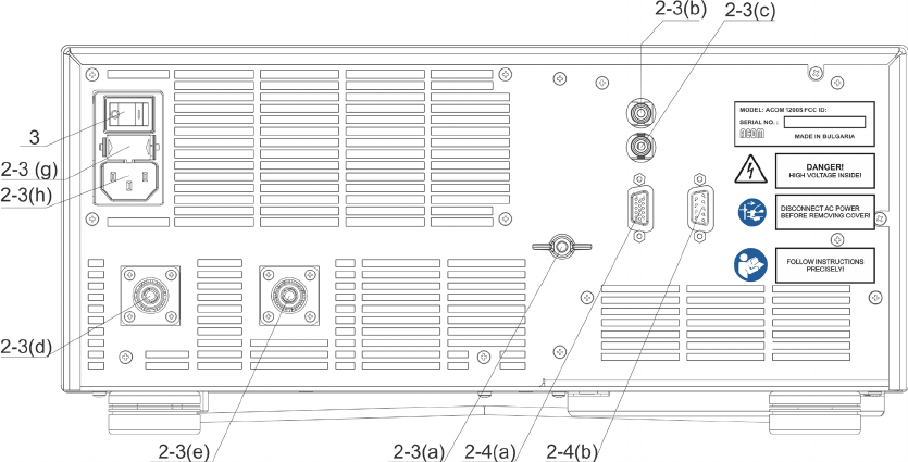
a) GND stud - First connect the grounding stud of the amplier (located on the rear panel and
marked GND – Fig. 2-1) to the grounding system of the shack.
7
b) KEY-IN jack - amplier input for receive/transmit control from the transceiver.
The transceiver switches the amplier from receive mode into transmit mode (RX/TX) by grounding of
the KEY-IN input.
Run a shielded cable from the output of your transceiver, providing “ground on transmit”, to the KEY-IN
input on the amplier rear panel (RCA PHONO jack – Fig. 2-1). Use a standard RCA PHONO plug for
connection to the amplier.
Transceiver manufacturers give different names to this output, for example: TX-GND, SEND, T/R LINE,
RELAY, and others. At some transceivers “ground on transmit” output should be activated by a menu
or via changing a switch on the rear panel or inside the transceiver. See instructions in your transceiver
manual.
N O T E
Voltage on the KEY-IN jack does not exceed 12V and the current
is below 6mA. See also S. 8-2(a).
N O T E
Your amplier will not work if the KEY-IN input is not connected
correctly. If you experience any difculty consult your dealer.
Fig. 2-1 Rear panel connections
c) KEY-OUT jack - transmit-enabling control output from amplier to the transceiver.
The KEY-OUT jack on the rear panel provides an extra control signal from the amplier to the transceiver.
This can be used for improving the receive/transmit (RX/TX) switching safety.
C A U T I O N
KEY-OUT is a low-powered open-collector output, make sure
that the signal voltage coming from the respective transceiver
connection does not exceed 50VDC (open circuit) and the closed-
circuit current is below 20mA.
If your transceiver has a suitable input, that disables transmission unless grounded externally, we
recommend this to be connected to the KEY-OUT jack of the amplier. Use shielded cable terminated
with а standard RCA PHONO plug.

88
The transceivers manufacturers give different names to this input, for example: TX-INHIBIT, MUTE,
LINEAR, and others. Check the manual of your transceiver. Approach your dealer for details. If your
transceiver has no such input, do not worry – ACOM 1200S will operate normally with KEY-OUT
unconnected.
d) RF INPUT - Connect a coaxial cable with a PL-259 plug from the transceiver output
(antenna jack) to the amplier RF INPUT jack.
C A U T I O N
In order to avoid at damage, turn off your transceiver’s internal antenna tuner.
e) RF OUTPUT - Connect a suitable coaxial cable with a PL-259 plug from the RF OUTPUT
on the rear amplier panel to the antenna switch, tuner or antenna intended for the
respective frequency band.
C A U T I O N
If you use an amplier for the rst time in your shack, pay serious
attention to the size of coaxial cable from your amplier output
to the antenna. The cable must be capable of handling the
increased power safely, particularly on the 10m and 6m bands.
This warning applies equally to the antenna switch, tuner, and
the whole antenna system, especially multi-band trap antennas.
We recommend using RG213 or better. Consult your local coax cable supplier.
f) Preparation of the mains outlet for the amplier, requirements for the installation and
the mains voltage.
C A U T I O N
Before connecting your amplier to the power grid, be sure
that the outlet is correctly wired and is capable of providing the
required current i.e. (up to 10A from 200/240VAC mains and up to
16A from 100/120VAC mains). Also make sure that the grounding
lead is connected properly in the outlet, intended for the amplier.
If subsequently you connect the amplier to a different outlet,
check it as well.
It is preferable to use the mains outlet closest to the source. Make sure that the respective fuses and
voltage, of your power mains match the ACOM 1200S amplier’s specications (see S. 8-1(g)).
g) Main fuses.
C A U T I O N
Make sure you check whether the main fuses installed in
your amplier correspond to your local mains nominal voltage
and if necessary replace them as described in Section 7-2!
h) Power cord socket. Due to different mains standards in different countries, the
ACOM1200S is delivered without a power plug for the mains cable. You dealer might
be able to provide the correct Safety Class I plug. The ground lead of the power cable
is colored yellow with two green stripes. If you have any doubts about the correct way
to connect these wires, consult your dealer.

9
2-4. Installing options and connecting to external devices (transceiver,
computer, etc.)
a) CAT/AUX interface – used for connecting and operating with various transceiver models (see
table 2-1 below and the respective menu in S. 5-3, table 5-1 and Fig. 5-3).
Most of the modern transceivers can be connected by CAT to the ACOM 1200S. This will allow the
amplier to track the transceiver frequency without any transmission and change the bands automatically
when in Operate mode. The cable can be supplied optionally, ordered separately or home brewed
according to table 2-1 and the transceiver’s manual.
The CAT connection requires a cable made especially for the ACOM 1200S and your transceiver. Wiring
diagrams of such cables can be found at www.acom-bg.com.
Note that some of the connections - to the transceiver’s BCD band data outputs and Band Voltage
outputs do not provide an exact frequency data, but only band data. Those connections cannot be
used when ACOM 1200S works together with ACOM 04AT because the tuner needs to know the exact
frequency, not the band.
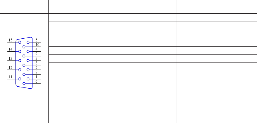
Table 2-1 shows the signals and the pin out of the CAT/AUX connector - rear panel of the amplier.
Table 2-1
CAT/AUX
interface
PIN
NO. PIN NAME DESCRIPTION SPECIFICATIONS
Rear panel
view
1 RxD Received Data TTL input
2 RxD Received Data RS232 input
3 TxD Transmitted Data RS232 output
4 TxD Transmitted Data TTL output
5 GND Ground 0 Volt
6 BAND voltage Analogue input 0 to +8V
7 Band data 0 Bit 0 TTL input
8 Band data 1 Bit 1 TTL input
9 Band data 2 Bit 2 TTL input
10 Band data 3 Bit 3 TTL input
11 ON RMT Remote Pwr On +4.5 to + 15V / 3mA max
12 Debug mode CPU only Pwr Input +8 to + 15V / 0.4A
13 KEY-IN Tx Request Less than +12V / 6mA
14 KEY-OUT Tx Ready O.C. output, up to
+50V / 20mA
15 GND Ground 0 Volt
b) RS232 port. Table 2-2 shows signals and pinout of the RS232 port on the amplier’s rear panel.
This connector may remain unused until you decide to control the amplier remotely.
1010
Table 2-2
RS 232
interface
PIN
NO. PIN NAME DESCRIPTION SPECIFICATIONS
Rear panel
view
1 - Not connected -
2 TxD Transmitted Data RS232 level output
3 RxD Received Data RS232 level input
4 - Not connected -
5 GND Ground 0 Volt
6 DSR Remote Power On RS232 level input
7 - Not connected -
8 CTS Remote Power On RS232 level input
9 - Not connected -
3. INITIAL POWER ON AND OPERATION
C A U T I O N
Do not turn the amplier on at least two hours after unpacking it
and installing in its nal operating position. Pay special attention
whenever the amplier is moved from a very cold place to a very
warm one because condensation may develop on the inside
resulting in damage to the high voltage circuits of the amplier.
Under these circumstances, do not turn the amplier on for at least
4 hours. A similar effect could occur following a rapid warming of
the room, such as winter usage of a powerful electric heater.
After following all instructions in Section 2 INSTALLATION, check whether the rear panel mains switch
is turned off. Then plug the amplier in the mains outlet.
3-1. Low energy standby mode of the power supply
Now you can turn on the mains switch on the rear panel. This will activate only the low-energy stand-by
mode of the amplier power supply and will light up the red LED above POWER button, while the main
power supply is still off and the display is dark.
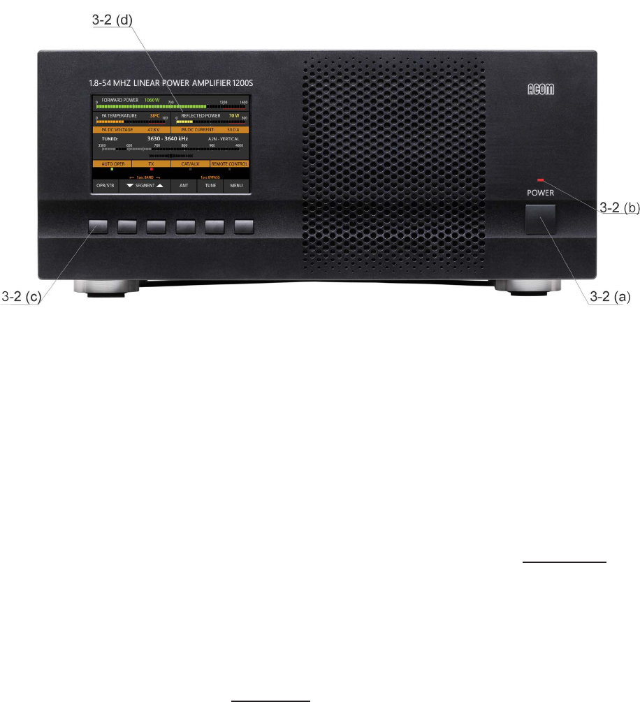
3-2. Front panel - controls and readouts
a) POWER button. When the rear panel mains switch is turned on, push and hold 1-2 seconds to
start the amplier up. When the amplier is turned on, push to turn it off (back to standby mode).
b) LED indicator above the POWER button. When lit red and the screen is dark, the amplier is in
standby mode and may be turned on by pushing the POWER button.
11
Fig. 3-1 Front panel
c) 6 functional buttons keypad for manual (local) control of the amplier. The function of each
button is indicated on the display above it. Depending on the displayed menu, the buttons may
have different functions.
d) A color display showing the operating information.
3-3. Initial turning on
In order start up the amplier, push and hold the POWER button on the front panel for one or two
seconds - аbout ten seconds later (boot sequence) the display will ash and show the basic screen with
the amplier information - Fig. 3-2.
The amplier may start either in Stand-by or in Operate mode – see S. 5-4 USER PREFERENCES -
AUTO OPERATE.
3-4. Basic screen
There are 9 information areas on the basic screen:
a) Information area for the frequency band – the edges of the currently selected BAND are
displayed.
If the amplier doesn’t receive any operating frequency data from CAT or via RS232, it will switch to the
last used band at startup.
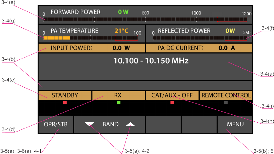
1212
Fig. 3-2 Basic screen
b) Operating values and alarm messages area.
Any two operating values selected in the AMP MEASURE menu (S. 5-1) will be shown here.
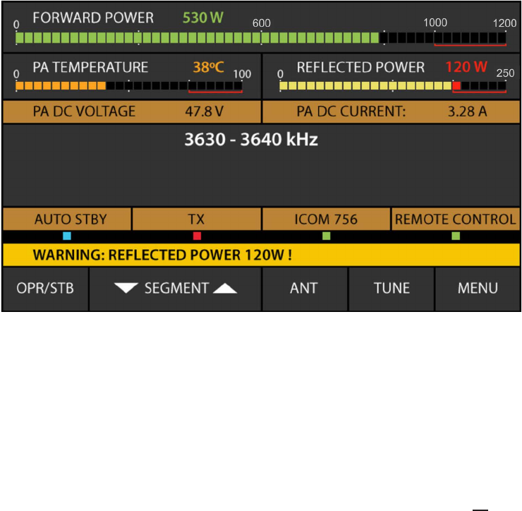
The alarm messages (either WARNING or SOFT FAULT) appear on yellow background on the same
area and are ashing frequently in order to attract the operator’s attention (Fig. 4-1).
The WARNING messages appear only temporarily (for about three seconds), afterwards the indication
of the operating values is restored automatically (S. 4-4(a).
The SOFT FAULT messages appear in the same eld but they remain on the screen until the AUTO
OPERATE time is elapsed (S.4-1(c)) or until the operator pushes any button, then the operating values
indication is restored too.
c) Working mode indicator - OPR, STB or AUTO OPER (S. 4-1).
d) RX/TX indicator - reads the request for transmit (KEY-IN input). The RX indication is green and
the TX is red. The indicator will ash frequently if switch over is impossible.
e) Forward power bargraph and digital readout. Displays the power fed into the antenna.
f) Reected power bargraph and readout. Entering the red zone is not allowed.
g) PA transistor temperature bargraph and readout. Entering the red zone is not allowed.
h) CAT interface information. When CAT is deactivated, this eld is shaded.
i) REMOTE CONTROL information eld–ashing represents RS232 port dataow.
13
3-5. Control system – buttons and menus
a) The OPR/STB and the BAND buttons are used for manual (local) control of the (Fig. 3-2):
- the left-most button OPR/STB switches over the amplier between Operate and Stand-by
modes;
- the next two buttons – BAND up and down arrows - change the frequency bands in ascending
or descending order;
b) The right-most button MENU (Fig. 3-2) provides access to the amplier’s settings and service
functions;
- in each menu the left-most button is always HELP and the right-most – always EXIT;
- the HELP button provides information about the current screen;
For more details of the control system and use of the menus see Section 5. MENUS – USEFUL TOOLS
AND OPTIONS.
3-6. Test transmission
To make sure that you have installed the amplier correctly, make a test transmission as described
below. Repeat these tests for each new band and antenna, as well as after installing a new or repaired
antenna, antenna switch, tuner, and / or the connecting cables.
a) Check of RF by-pass path of a non-driven amplier.
For this check the amplier must be completely installed and connected according to Section 2, but not
powered by the mains, i.e. the POWER ON switch on the rear panel must be turned off. In any case the
LED above the POWER button must be dark for this test.
First, check if the transceiver’s reception is normal. If you observe a signicant worsening of reception,
rst check for a problem in the coaxial connections to the amplier (S. 2-3(d),(e)).
If reception is normal, prepare the transceiver as follows:
- select a continuous carrier mode (CW, RTTY, FM);
- switch the microphone off (decrease the mic gain), disable FSK;
- reduce the output power control to a minimum;
- select a suitable indication so that you can watch the RF power and SWR at the transceiver
output;
- if the transceiver has a built-in antenna tuner – switch it off.
Now in receive mode select a frequency which is not occupied at the moment and press shortly the
PTT or TX key while watching the output power and the SWR readings. If the power or SWR at the
transceiver output are too high (over 5W or SWR over 2:1) release the key and check for the reason as
follows:
- check again whether the power control is set at minimum;
- check whether the frequency is within the operating range of the selected antenna;
1414
- check the good working order of the coaxial cables, connectors, and feed lines from the
transceiver antenna jack through the amplier, the antenna switch or external tuner (if there is
one) to the BALUN transformer, and the antenna itself (S. 2-3(e)).
If the power and SWR are as expected, transmit again and while watching the power and the SWR
readings, increase transceiver power gradually from minimum to maximum (but not more than 200W, in
order to not overload the RF by-pass circuit of the amplier).
If SWR remains below 2:1 (preferably below 1.5:1) at the last test, decrease the power from the
transceiver to minimum again and continue with the next check-up.
b) Check-up in Stand-by mode.
Turn the amplier on, as described in Sections 3-1 to 3-4 (Fig. 3-2).
Make sure that the amplier is in Stand-by mode. Push the OPR/STB button if needed.
Repeat receive and transmit tests as it was done with the amplier turned off. During these tests note
also whether the forward and reected power bargraph and digital readout (S. 3.4(e),(f)) show respective
RF power presence. If the reected power exceeds the forward power, verify that the input and output
coaxial cables to the amplier are not interchanged (S. 2-3(d),(e)).
N O T E
The power indication accuracy is optimized around the 1000W level
and usually it is unreliable below 50W.
c) Entering Operate mode.
At Operate mode the transceiver receiving should not suffer. If it worsens and together with this the
indicator RX changes into TX although the transceiver is in receive mode, check the control cable
connected to the KEY-IN input – S. 2-3(b) for a short circuit. The connection to the transceiver could be
wrong too.
d) Test transmission.
Switch to the same band as the transceiver and antenna.
Set the transceiver to a continuous carrier and minimum power. In Operate mode choose a free frequency
and push the PTT or CW key briey, while watching the amplier’s behavior:
- RX mode must have changed to TX;
- the reected power must read below 20W;
- the forward power must read between 20 and 150W with minimum drive power from the
transceiver (between 1 and 5W);
If the above test goes normally, push briey the PTT once again, this time watching the transceiver’s
SWR reading (i.e. the input SWR of the amplier) – this must be below 1.2:1.
e) Setting of drive level and typical operation.
After the successful passing of the above tests push PTT or CW key for several seconds, watching the
forward and reected power. Increase the drive power until the forward power at the amplier’s output
reaches 1000W.

15
Upon reaching 1000W forward power check the following parameters (continuous carrier operation):
- the reected power must not exceed 110W (for SWR 2:1) or better still to be below 40W (for
SWR 1.5:1);
- PA DC CURRENT must be between 32 and 36A; it is normal that the current varies within these
limits when changing operating frequency and antenna impedance;
- PA DC VOLTAGE must be within 48 – 52V;
- the transceiver’s SWR reading must be below 1.2:1.
Enter the MEASURE menu and check:
- the drive power from the transceiver must be between 30 and 50W;
- PA BIAS, which must be between 1.8 and 2.0V (typically 1.9V);
- PA TEMPERATURE, which must be between the ambient and 80ºC (176ºF), depending on the
power level and the duration of transmission.
f) Elimination of electromagnetic compatibility (EMC) problems.
If you use an amplier for the rst time in your shack, you may need to make some improvements in the
setup. It is possible you might experience tingling from metallic objects due to the stronger radiated RF
eld. It could affect the operation of your station or systems outside, if they are too sensitive – typical
examples are the microphone, CW keyer, computer keyboard / mouse, as well as TV receivers, Hi-Fi,
intercom or telephone setups and others.
For instance, induction of RF currents into the microphone, CW keyer or computer keyboard, may lead
to distortions in the peaks or self-oscillation in SSB mode, “sticking” or breaking off the dots or dashes
from a Morse keyer, or garbling computer screen images. For the elimination of such problems we
recommend that you take the following general measures:
- minimize the radiation from the feed lines by reducing the common mode currents in them,
improve the balance of antennas and feedlines;
- in case you use asymmetric antennas (GP and similar) install as many radials as practical (use
a well-developed counterpoise system);
- add current chokes on the coaxial feeders;
- place as far away as possible (also by height) the radiating elements of antennas from the
premises, where the affected devices are located; in this sense, asymmetrical antennas without
a separate feeder (Long Wire, Windom, and similar) may cause more interference because their
radiating element begins immediately from the shack (part of it is the feeder itself);
- if the use of asymmetrical directly fed “wire” antennas is inevitable, use mainly half wave or half
wave multiple – they have a high input impedance, operate respectively with a small current
in the feed point, and in the grounding of the shack; thus you can reduce the strength of the
disturbing RF elds more than 10 times (at the same radiated power) compared to the case
with quarter-wave and multiple to quarter-wave antennas of this class – you should avoid them
because they have a low input impedance and operate with a large RF current in the grounding
system and in the power supply network respectively, i.e. they create stronger disturbances
(RFI);

1616
- improve the RF grounding system: use the shortest and widest possible metal strips for the
connections to ground and between the different gear in the shack; connect one or more
counterpoises (sized for the problematic band) to the feeder shield at the point, where it enters
the building, and the same point - with the possibly shortest and widest connections - to the
grounding system: this is a very efcient measure, in particular if the shack is located on a high
oor above ground;
- to reduce the RF impedance of the grounding connections sheet metal stripes instead of exible
braids are preferred;
- thread ferrite beads or snap-in ferrites with medium permeability (800-4000) over the power
cord, the feeder and the signal cables leading to the affected devices (TV etc); besides the
size, consider the frequency range in which the offered ferrites are effective – normally they
are optimized for suppression of interferences on HF (with larger permeability), with medium
permeability for HF-VHF or with low permeability - only the VHF range. The latter are ineffective
for HF;
- whenever possible use shielded cables and ground their shields at both ends;
- the addition of even quite simple low pass L/C or R/C lters directly to the disturbed inputs or
outputs of the devices is very effective, provided it is practically applicable.
Last but not least, bear in mind that the benet of the above measures is two-fold. Firstly - they reduce
the interferences from your transmissions to the ambient environment and secondly - they reduce the
background noise oor for your reception. Practically, with no great efforts, implementing the above
measures, you can reduce the background noise oor with one or more S-units across the different
bands. This will allow you not to miss weaker stations, which will hear you because of your increased
transmission power.
4. AMPLIFIER OPERATION
4-1. Change of modes RX/TX and Operate/Stand-by; AUTO OPERATE
option
a) In Stand-by mode, as well as in the unpowered state, receiving and transmitting with the
transceiver is done via RF bypass between RF INPUT and RF OUTPUT of the amplier.
In Standby, the transceiver’s RF power is not amplied, the control KEY-IN input does
not affect the operation, and the KEY-OUT output (S. 2-3(c)) follows the state of the KEY-
IN input unconditionally. The bands cannot be changed neither manually nor by CAT or
remotely.
b) In Operate mode the receive-transmit (RX/TX) direction is controlled by the KEY-IN input:
- at open KEY-IN (Operate/RX mode), the transceiver receives the signals from the antenna
through the same RF by-pass path between RF INPUT and RF OUTPUT as with amplier
turned off or in Stand-by mode;
- at grounded KEY-IN ((Operate/TX mode) the RF drive is amplied and fed to the antenna
through the RF OUTPUT connector.

17
C A U T I O N
In order to provide time for the relays to switch safely from receive
to transmit, the transceiver should provide a dead time i.e. must
“notify” the amplier in due time by grounding the control KEY
IN input not later than 10ms before feeding drive power toward
the amplier RF input. Otherwise, the protection system will read
“HOT SWITCHING ATTEMPT” and will trip off.
In Operate mode the KEY OUT output (S. 2-3(c)) follows the state of the KEY-IN input only after all
conditions for safe transmission have been found good by the amplier control unit. The KEY OUT
output duly disables transmission, if the amplier is not ready.
The two modes - Operate and Stand-by - may alternatively be changed:
- either manually (locally) – by pressing the OPR/STB button – see the basic screen in Fig. 3-2,
or automatically – when if the AUTO OPERATE option is activated – see S. 5-4(c).
N O T E
Access to the Operate mode can be locked in the AMP SERVICE
menu, the OPERATE ACCESS option (S. 5-2 and Fig. 5-2).
c) AUTO OPERATE option can be turned on/off by the operator in the USER PREFERENCES
menu – S. 5-4 and Fig. 5-4 - or by a remote control command.
When the AUTO OPERATE option is OFF, the two modes Operate and Stand-by can be changed
alternatively by the OPR/STB button or by a remote control command. At a SOFT FAULT protection trip,
the amplier will revert to Stand-by and wait for the operator to return it to Operate by pressing the OPR/
STB button.
When AUTO OPERATE is ON (S. 5-4), the amplier will start up in Operate mode. At a SOFT FAULT
protection trip, the amplier will rst revert to Stand-by, but will return automatically to Operate mode in
about 4 seconds.
Even at AUTO OPERATE on, the operator can revert to and remain in a Stand-by mode manually by the
OPR/STB button or by a remote command. The next OPR/STB button push will switch the amplier to
the Operate mode and restore the normal operation of the AUTO OPERATE option.
4-2. Band change, standard and expanded frequency coverage
When connected to a transceiver with CAT, the amplier will change frequency bands automatically,
following the transceiver’s operating frequency changes.
Without CAT connection, the bands can be changed either manually or automatically (by the built-in
frequency counter).
The bands are changed manually by the up and down BAND buttons.
For an automatic band change via the built-in frequency counter, make a quite short pre-transmission
(100ms is enough) – a CW dit, or a sound on SSB) and release a PTT for a moment before the main
transmission.
If the new frequency is out of the amplier’s frequency range (S. 8-1(a)), the transmission request will
be denied and the following fault message will appear on the screen:
“FREQUENCY OUT OF RANGE”
The amplier specications are guaranteed within the bands listed in S. 8-1(a)). Frquency coverage
changes could be negotiated with the manufacturer.
1818
4-3. Operation with an external antenna tuner
At antenna SWR over 1.5:1, it is advisable you use an external tuner. The ACOM 04AT Remote
Automatic Antenna Tuner is designed to work with the ACOM 1200S. Use of other antenna tuners is not
recommended.
4-4. Automatic protection system
The control unit (S. 7-3(b)) keeps track of most amplier analogue and logic signals in all modes.
Those are the receive/transmit control signal, the output relay contact state and switching times, the
RF drive frequency and drive power (the input power), the nal transistors DC current and DC voltage
on the drains as well as, the gates bias voltage and the heat sink temperature, the main power supply
components temperature, the RF output forward and reected power, and others. Some derivative
parameters, as the power gain, the SWR, the heat power dissipated by the nal transistors dynamically
and others, are watched too.
In the event a parameter maximum is exceeded, the amplier will assess the risk and will trigger one
of the three levels of protection, as described in items (a) to (c) below. Every event is accompanied by
a warning text on the screen (Fig. 4-1). A sound alarm will be also produced, if set on in the “USER
PRE F ERE N CES ”– g . 5- 4.
Fig. 4-1 – Appearance of an alarm message
a) The rst protection level is WARNING. When a value watched by the control unit approaches
the protection threshold, the transmission is not interrupted, but a message appears – for
example “Drive Power too High”, “Drain Current too High”, or another – Fig. 4-1.
You can continue to transmit in these conditions, but you have to take some measures, for example, to
reduce a bit the drive power from the transceiver. The warnings remain on the screen for at least three
seconds so that they can be read through and will disappear after the reason has dropped off.
b) The second protection level is a SOFT FAULT – when a value exceedsed the safe level,
but does not put the amplier in a danger of a failure.
At the second level (SOFT FAULT) the amplier reverts to Stand-by mode for four seconds or permanently
19
depending on whether the “AUTO OPERATE” option had been activated. A respective message is
shown on the screen, for example “Excessive Reected Power”, “Excessive Drain Current”, and others,
as well as with a sound alarm (unless the sound had not been muted – S. 5-4).
Unlike those for a WARNING, the SOFT FAULT messages remain on the screen and persist until the
operator pushes any button - in order to conrm that the message is read - or until the OPERATE mode
will be resumed automatically when the AUTO OPERATE is active – S. 5-4).
SOFT FAULT’s call for fast and simple correcting actions by the operator, such as, for example, reducing
the drive power, improving of load SWR through retuning the antenna tuner, antenna change, etc.
c) The third and most serious protection level is a HARD FAULT. The amplier will be turned
off automatically to avoid possible further damages.
When the protection trips off, the data about the fault is stored in the memory and the front panel screen
is blanked. There is also a sound alarm - a series of CW letter F.
If the reason for tripping the protection is not obvious, you can try to turn on the amplier. If the amplier
allows it after the fault, a fault message will appear with information about the reason for the latest
automatic shutdown (for example, overheating of the power supply unit or of the PA stage).
After pushing any button, the fault message will disappear, and if there are no current problems (for
example, the overheated unit has already cooled down), the amplier operation will be restored. In
the event a parameter maximum is exceeded again, a new message will appear on the screen, or the
protection will trip again immediately after the recovery attempt.
If the problem persists, contact your dealer – S. 1-2.
At each “HARD FAULT” shutdown the amplier stores data, concerning the controls and values, the trip
time, and others. Your dealer or his service may ask you to read this data out from the amplier screen
or by RS232 interface and store it in a computer le – see menu FAULTS LOG, Sections 5-5 and 7-4.
5. MENUS – SETTINGS AND OPTIONS
By pushing the MENU button (the rightmost) the user invokes the menu selection screen (Fig. 5). Each
menu can be selected by the ITEM (up and down) buttons and SELECT.
The items in each menu are selected and controlled by the same six buttons as in the basic screen,
but they have new functions.
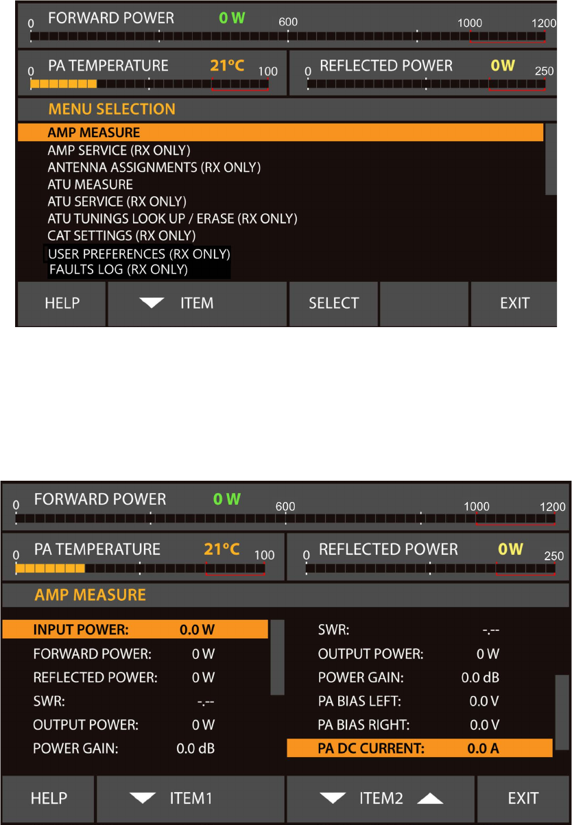
2020
Fig. 5 - MENU SELECTION
5-1. Menu „Amplier measurements” – AMP MEASURE
The menu AMP MEASURE (Fig. 5-1) is accessible from the MENU SELECTION screen (Fig. 5) in all
modes. 11 parameter values be observed continuously.
Fig. 5-1 Menu “Amplier measurements” – AMP MEASURE
Two identical lists appear on the left and the right halves of the screen, each one containing the same
11 values.
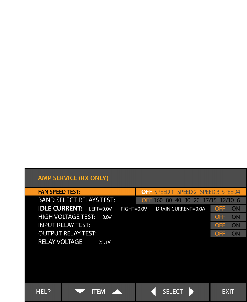
21
Any value can be selected in each screen half. Using buttons ITEM1 and ITEM2 (up and down) select
the desired values. The two slected values will be shown continuously on the basic screen (S.3-2 (b),
Fig. 3-2) - after leaving this menu (EXIT button).
5-2. Menu “Amplier service functions” – AMP SERVICE.
The amplier service menu (Fig. 5-2) is accessible from the MENU SELECTION screen (Fig. 5) at RX
mode only.
C A U T I O N
The AMP SERVICE menu is used for checking and adjustment
of the zero-signal (idle) drain current of the nal transistors and
for testing some functions and circuits of the amplier when
serviced. We recommend these procedures are carried out only
by a trained service technician!
The necessary service function is selected with the ITEM buttons (up and down). With the SELECT
buttons (left or right) the selected function is turned ON or OFF.
The inactive functions are greyed out and the active are red. When leaving a function submenu, it is
turned off and deactivated automatically. At pressing the EXIT button all service functions are turned off,
and the MENU SELECTION screen comes back (Fig. 5). At consecutive pushing of the EXIT button, the
basic screen returns (Fig. 3-2).
Fig. 5.2 Menu “Service functions in the amplier” – AMP SERVICE
5-3. CAT SETTINGS MENU
After a CAT cable is connected to both the transceiver and amplier, the correct settings for the
transceiver have to be entered via this menu. If there is no CAT connection, OFF has to be selected as
Interface type.
The CAT settings are accessible only in RX mode – Fig. 5 and 5-3. The item is selected by the ITEM
buttons (up and down). The value is set with the SELECT buttons (left or right).
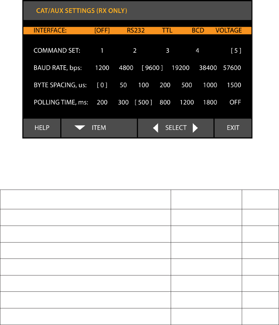
2222
If the amplier CAT port is connected either to the transceiver BCD Band Data or Band Voltage output,
select the respective interface type and push EXIT. The other items and values will not be taken into
account.
If the CAT cable is plugged into the transceiver’s serial port, select the interface and command set
according to Table 5-1. The baud rate has to be set to the same value as the transceiver’s. The byte
spacing and polling time may be left unchanged.
Last select the interface type (RS232 or TTL) according to the table 5-1 and used connection and
push EXIT.
Fig. 5-3 Menu “Selection of CAT/AUX interface” – CAT/AUX SETTINGS
Table 5-1
TRANSCEIVER INTERFACE COMM
SET
ELECRAFT RS232 5
ICOM (Connection to the REMOTE jack) TTL 1
ICOM (Connection to the RS232 port or CT17) RS232 1
KENWOOD TS-2000, 480, 590, 990 and similar RS232 5
YAESU FT-450, 950, 991, 1200, 2000, 3000,
5000, 9000 and similar RS232 2
YAESU FT-1000MP RS232 4
YAESU FT-817, 857, 897 TTL 3
23
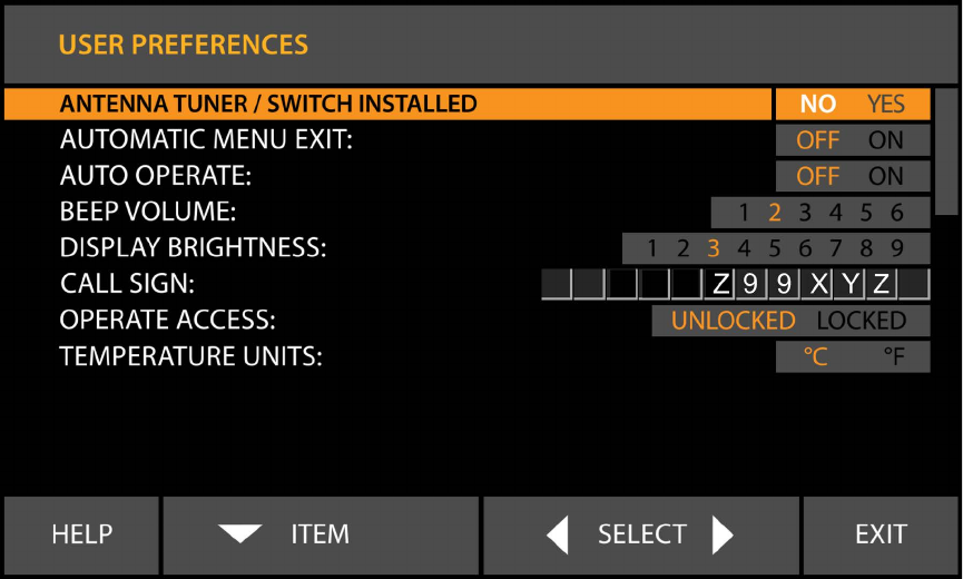
5-4. “USER PREFERENCES” menu
Fig. 5-4 – Menu USER PREFERENCES
a) ANTENNA TUNER/SWITCH INSTALLED.
If ACOM 04AT remote automatic antenna tuner is also installed, select YES. Refer to ACOM 04AT
Operating Manual.
b) AUTOMATIC MENU EXIT.
When the option is turned on, the amplier exits the currently selected menu if no button has been
pressed for more than 5 minutes.
If the option is turned off, the amplier remains in the currently selected menu until the EXIT button is
pushed.
c) AUTO OPERATE.
The AUTO OPERATE option is described in Sections 3-3, 4-1(c), and 4-6(b).
d) CALL SIGN
If entered here, a call sign (or another text) will be included in any Fault Log le generated by the
amplier. The call sign (or another text) will not replace ACOM 1200S logo on the startup screen.
Use the SELECT button to select the character position. The ITEM button changes the characters.
Finish by moving the pointer out of the editable elds by means of the Left SELECT button.
e) OPERATE ACCESS
When locked, the amplier remains in Standby and cannot be switched to Operate unless unlocked in
the same menu. Passwords are not used – this is only a simple protection against possible child actions,
2424
or involuntary switching to Operate mode. While locked, an attempt for entering Operate mode will result
in a message:
“OPERATE MODE IS LOCKED”
The other preference items need no explanation.
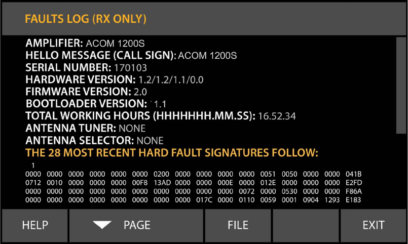
5-5. FAULTS LOG
This function reads on the screen the information stored in the memory about the last 28 HARD FAULT
protection trips (Fig.5-5). By pushing the FILE button, the information may be also downloaded in a plain-
text format le through the RS232 port and a computer using a standard terminal emulating program
(TTY). The RS232 protocol is: 9600, 8 N 1.
Fig. 5-5 Function FAULTS LOG
5-6. RESTORE DEFAULT SETTINGS
Four different factory reset levels are available (Fig.5-6).
In order to conrm the selected action the operator must push the ACTION - left (YES) button once
more. After restoring the default settings, the control will return to the MENU SELECTION screen - Fig.
5. If the ACTION – right (NO) button is pressed, the “NO” is selected again, and the control will not leave
the current position. At pressing the EXIT button in this position, the control leaves this menu without
changing anything and returns in the previous window (the MENU SELECTION screen – Fig. 5).
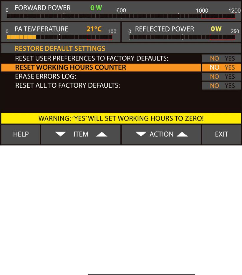
25
Fig. 5-6 Menu: RESTORE DEFAULT SETTINGS
6. REMOTE CONTROL
6-1. General information
The ACOM 1200S may be controlled remotely by the RS232 port.
The ACOM 1200S RS232 interface protocol is available on www.acom-bg.com.
7. MAINTENANCE
W A R N I N G HIGH VOLTAGE!
The mains line voltage and a high DC voltage of up to 500V
inside the ACOM 1200S amplier are both LETHAL! For
your safety, pull the amplier power plug out of the mains
wall outlet and WAIT AT LEAST three minutes EACH TIME
BEFORE servicing the amplier!
7-1. Periodic maintenance; general checks and cleaning
a) Periodically (but at least once per year) check all connections, contact cleanliness and the
tightening of all connectors, in particular the coaxial ones.
Check the integrity of the cables, in particular when they are layed on the oor. Check also if the cables
are secured well in the area where they come out of the connector body.
Pay particular attention to the mains plug and the wall outlet – if you have any doubts consult with an
electrician.
2626
Periodically check the SWR of the antennas and if this changes over time. Problems could occur more
often in poor weather conditions – rain, snow, strong wind etc.
b) Periodically (more often in a dusty environment, but at least once per year) clean the air lters
without opening the amplier.
W A R N I N G
The air lters may be too dusty - be careful how you
clean them so that you DO NOT INHALE (BREATHE IN)
neither spill the dust over! Wrap it, for instance, in a
wet cloth before cleaning!
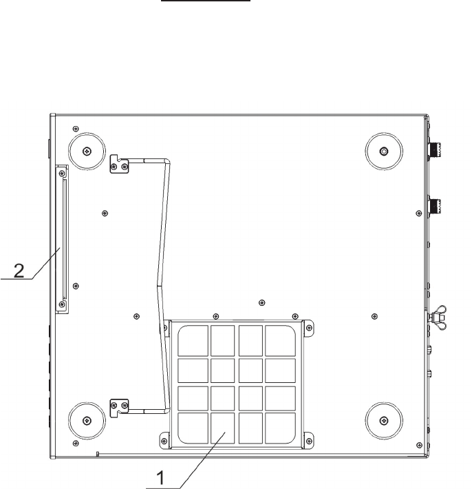
Fig. 7-1 – Bottom view - Air lters
ACOM 1200S has two air lters that are accessible from the bottom - see Fig. 7-1. Use a Philips-1
screwdriver to remove the square lter cover from the PA air lter (1). Remove the cover and take out
gently the foam-like plastic lter. To remove the PS air lter (2) unscrew the 2 mounting screws. Using
a small at srewdriver or tweezers gently lift the lter tray away from the amplier body. Carefully clean
the lters and covers from dust, wash them with tap water and leave them to dry up before you mount
them back.
Clean also (as far as possible from outside without opening the amplier) all ventilation apertures on the
cover and the chassis, including ones at the bottom. Finally, mount the air lters in reverse order and
screw the screws tightly.

27
C A U T I O N
Do not use solvents for cleaning – they can be dangerous to you,
as well as to the coating or the amplier plastic parts.
In case of need, clean up the amplier outside surfaces without opening it. Use a soft piece of cotton
cloth, slightly moistened with clean water.
7-2. Replacement of fuses
W A R N I N G HIGH VOLTAGE!
If replacement of fuses is necessary, rst pull out the
amplier mains plug from the mains outlet and wait for at
least 3 minutes!
The main fuses of the amplier are located on the rear panel – Fig. 2-1.
The fuses must be of the fast type, European size 5x20mm, rated for 250VAC and rated as follows:
C A U T I O N
The fuses must be rated for a current corresponding to your
mains nominal voltage: 16А for operation from 100-120VAC
mains voltage or 10А for operation from 200-240VAC. Use
only standard fuses!
C A U T I O N
Never replace any fuses inside the amplier without special
instructions from your dealer! Blown internal fuses can be a
symptom of a more serious problem, which should be resolved
beforehand. Unauthorized replacement of inside fuses infringes
the warranty conditions!
7-3. Using the fault codes (signatures) for diagnostics
The data of the last 28 HARD FAULT protection trips is stored in the amplier memory – see S. 4-6(c).
The data can be downloaded from the memory through the RS232 port and stored in a computer le
even if the amplier cannot be turned on after a serious fault – only external power has to be fed to the
Control unit in either of the following ways:
- 8 to 15V DC voltage applied to the “Debug mode” input (Table 2-1) of the CAT/AUX port. The
power supply has to be capable to provide 0.4A of current;
- if the Control board has already been removed from the amplier, it can be powered directly with
+5V (0.4A) and the fault log downloaded via the RS232 port.
In the FAULT LOG reading mode (Fig. 5-5), the Control board automatically transmits the data from the
memory trough the RS232 interface. Depending on the number of fault events stored in the memory, the
transmission may take between 0.5 and 12 seconds. A pause of 6 seconds follows, than transmission
starts again. The data can be read in a plain-text format with a computer, using a standard terminal
program.
You can send the recorded le to your dealer or to ACOM accordingly. They could also provide the
2828
necessary instructions, if you choose to decode the downloaded hexadecimal data by yourself.
7-4. FIRMWARE UPDATES
C A U T I O N
Before you change the firmware version, check the new version
compatibility with the revisions of the hardware and of the boot
loader in your amplier - see S. 5-5. If you have any doubts about
the versions, please consult your dealer before you undertake
any action.
When ACOM issues a new rmware version, the user can upload it in the amplier after he checks the
compatibility – see the note above.
When compatibility is conrmed a return to an earlier version is also possible.
8. SPECIFICATIONS
8-1. Parameters
a) Standard frequency coverage (*):
1.800 - 2.000 MHz
5.020 - 5.455 MHz
7.000 - 7.300 MHz
10.100 - 10.150 MHz
14.000 - 14.350 MHz
18.068 - 18.168 MHz
21.000 - 21.450 MHz
24.890 - 24.990 MHz
28.000 - 29.700 MHz
50.000 - 54.000 MHz
(*) Extensions or changes of the frequency coverage are possible on request.
b) Rated output power: 1000W +/-0.5dB, PEP or continuous carrier, without mode limitation 500W
with mains power supply voltage below 150VAC.
c) Intermodulation distortions (IM3): better than 31dB below the rated PEP.
d) Harmonic and parasitic emissions output suppression: better than 60dB (65dB typically).
e) Input and output impedances:
- nominal value: 50 Ohm unbalanced, UHF (SO239) type connectors;
- input circuit: broadband, SWR below 1.2:1 (1.1:1 typically); 1.8 – 54 MHz continuous range
without retuning or switching;
- RF by-pass path SWR - below 1.1:1, 1.8-54 MHz;
- acceptable SWR at the output load (the antenna): up to 3:1 with proportional power reduction
and up to 1.5:1 for full output power;
29
f) RF power gain: 14dB +/-1dB (typically 40W for 1000W output power);
g) Mains power supply voltage: 93-265VAC.Below 150VAC the output power is reduced.
h) Mains power consumption at full output power: 2100VA or less wth a power factor of 0.95 or
higher;
i) Mains power consumption in Low Energy (waiting) mode: less than 1VA;
j) Complies with EU safety regulations and electromagnetic compatibility standards, as well as
with the US Federal Communications Commission (FCC) rules;
k) Environmental conditions:
- temperature range: -10ºC to +40ºC (14ºF to 104ºF);
- relative air humidity: up to 95% @ 35ºC (95ºF);
l) Dimensions (projections not included) and weight, operating: (W x H x D) 372 x 171 x 427 mm
(14.6 x 6.7 x 16.8 In); 14.5 kg (32 Lbs).
8-2. Functions
a) Receive / transmit control:
- KEY-IN input – Phono RCA jack; voltage applied to the transceiver keying output up to +12V;
current drawn by the transceiver keying output up to 6mA;
- An optional KEY-OUT output – Phono RCA jack; output resistance: not more than 120 Ohm;
maximum safe input voltage from the transceiver +50V; maximum safe current drawn by the
transceiver: 20mA;
- minimum dead time, necessary for safe amplier switchingover from receive to transmit: 10ms
between the transmit request on the KEY IN input and the RF drive on the RF INPUT jack.
b) Frequency control directly by CAT from the transceiver.
c) Remote control through RS232 interface.
d) Remote power on by DSR/DTR and CTS/RTS lines on the RS232 port.
e) Remote power on/turn off by DC voltage impulse or continuous DC voltage on CAT/AUX port
ON_RMT input.
8-3. Storage and shipment
a) Environment conditions for storage and shipment:
- temperature range: -40ºC to +70ºC (-40ºF to 158ºF);
- relative air humidity: up to 75% @ 35ºC (95ºF);
- above sea-level: up to 12000m, including the luggage compartment of an aircraft.
b) Dimensions and weight at transportation (max): (W x H x D) 540 x 320 x 530 mm (20.9 x 12.6
x 21.2 In); 17kg (32 Lbs).
3030
9. DISCLAIMER of LIABILITY
All ACOM 1200S specications and descriptions are based on the latest information available
at the time of this document’s printing. As we are always striving to improve and update our
products, ALL PRODUCT, PRODUCT SPECIFICATIONS AND DATA ARE SUBJECT TO
CHANGE and ACOM reserves the right to make changes and improvements at any time without
further notice or obligation to notify any person or organization of such revisions or changes,
made in order to improve the reliability, function, quality and design and/or performance of the
ACOM 1200S. Further, this Operating Manual is provided “as is” and ACOM shall not be liable
for possible errors contained herein.

31
NOTES

3232
NOTES