ACSS an L 3 Communications and Thales TT-950 TCAS II User Manual Part 1
ACSS an L-3 Communications and Thales Company TCAS II Part 1
Contents
- 1. User Manual Part 1
- 2. User Manual Part 2
User Manual Part 1

Aviation Communication and Surveillance Systems
19810 North 7th Avenue
Phoenix, Arizona 85027--4400
U.S.A.
15 FEBRUARY 2003
34-43-20
Page T--1
PRINTED IN U.S.A. PUB. NO. 8000451--001
T2CAS
Traffic and Terrain Collision Avoidance
System
System Description and
Installation Manual

T2CAS / Part No. 9000000
SYSTEM DESCRIPTION AND INSTALLATION MANUAL
34-43-20
15 Feb 2003
Use or disclosure of information on this page is subject to the restrictions in the proprietary notice of this document.
Page T--2
PROPRIETARY NOTICE
This document and the information disclosed herein are proprietary data of ACSS. Neither this
document nor the information contained herein shall be used, reproduced, or disclosed to others
without the written authorization of ACSS, except to the extent required for installation or
maintenance of the recipient’s equipment.
NOTICE -- FREEDOM OF INFORMATION ACT (5 USC 552) AND DISCLOSURE OF
CONFIDENTIAL INFORMATION GENERALLY (18 USC 1905)
This document is being furnished in confidence by ACSS. The information disclosed herein falls
within exemption (b) (4) of 5 USC 552 and the prohibitions of 18 USC 1905.
S2003
ACSS is a U.S. registered trademark.
All other marks are owned by their respective companies.

T2CAS / Part No. 9000000
SYSTEM DESCRIPTION AND INSTALLATION MANUAL
34-43-20 15 Feb 2003
Use or disclosure of information on this page is subject to the restrictions in the proprietary notice of this document.
Page RR--1
RECORD OF REVISIONS
For each revision, put the revised pages in your manual and discard the superseded pages. Write
the revision number and date, date put in manual, and the incorporator’s initials in the applicable
columns on the Record of Revisions. The initial A shows ACSS is the incorporator.
Revision
Number Revision Date Date Put in Manual By

T2CAS / Part No. 9000000
SYSTEM DESCRIPTION AND INSTALLATION MANUAL
34-43-20
15 Feb 2003
Use or disclosure of information on this page is subject to the restrictions in the proprietary notice of this document.
Page RR--2
Blank Page

T2CAS / Part No. 9000000
SYSTEM DESCRIPTION AND INSTALLATION MANUAL
34-43-20 15 Feb 2003
Use or disclosure of information on this page is subject to the restrictions in the proprietary notice of this document.
Page RTR--1
RECORD OF TEMPORARY REVISIONS
Read the location instructions on each temporary revision page to know where to put the pages in
your manual. Remove temporary revision pages only when discard instructions are given. For
each temporary revision, give the correct data in the applicable columns.
Temporary
Revision No.
Temporary
Revision Date
Date Put
in Manual By *
Date Removed
from Manual By *
* The initial A in this column shows ACSS has done the task.

T2CAS / Part No. 9000000
SYSTEM DESCRIPTION AND INSTALLATION MANUAL
34-43-20 15 Feb 2003
Use or disclosure of information on this page is subject to the restrictions in the proprietary notice of this document.
Page RTR--2
Blank Page

T2CAS / Part No. 9000000
SYSTEM DESCRIPTION AND INSTALLATION MANUAL
34-43-20 15 Feb 2003
Use or disclosure of information on this page is subject to the restrictions in the proprietary notice of this document.
Page SBL--1
SERVICE BULLETIN LIST
Service Bulletin Identified
Mod
Date Included
in this Manual Description

T2CAS / Part No. 9000000
SYSTEM DESCRIPTION AND INSTALLATION MANUAL
34-43-20 15 Feb 2003
Use or disclosure of information on this page is subject to the restrictions in the proprietary notice of this document.
Page SBL--2
Blank Page

T2CAS / Part No. 9000000
SYSTEM DESCRIPTION AND INSTALLATION MANUAL
34-43-20 15 Feb 2003
Use or disclosure of information on this page is subject to the restrictions in the proprietary notice of this document.
LEP--1
LIST OF EFFECTIVE PAGES
Original -- 15 Feb 2003
Subheading and Page RevisionSubheading and Page Revision Subheading and Page Revision
Title
T--1
T--2 --
--
Record of Revisions
RR--1 --
RR--2 --
Record of Temporary Revisions
RTR--1 --
RTR--2 --
Service Bulletin List
SBL--1 --
SBL--2 --
List of Effective Pages
LEP--1 --
LEP--2 --
LEP--3 --
LEP--4 --
LEP--5 --
LEP--6 --
Table of Contents
TC--1 --
TC--2 --
TC--3 --
TC--4 --
TC--5 --
TC--6 --
TC--7 --
TC--8 --
TC--9 --
T C -- 1 0 --
T C -- 11 --
T C -- 1 2 --
T C -- 1 3 --
T C -- 1 4 --
Introduction
INTRO--1 --
INTRO--2 --
INTRO--3 --
INTRO--4 --
INTRO--5 --
INTRO--6 --
System Description
1--1 --
1--2 --
1--3 --
1--4 --
1--5 --
1--6 --
1--7 --
1--8 --
1--9 --
1--10 --
1--11 --
1--12 --
1--13 --
1--14 --
1--15 --
1--16 --
1--17 --
1--18 --
F 1--19/1--20 --
1--21 --
1--22 --
1--23 --
Hindicates changed, added, or deleted page.
F indicates right foldout page with blank back.

T2CAS / Part No. 9000000
SYSTEM DESCRIPTION AND INSTALLATION MANUAL
34-43-20
15 Feb 2003
Use or disclosure of information on this page is subject to the restrictions in the proprietary notice of this document.
LEP--2
1--24 --
1--25 --
1--26 --
1--27 --
1--28 --
1--29 --
1--30 --
1--31 --
1--32 --
1--33 --
1--34 --
1--35 --
1--36 --
F 1--37/1--38 --
1--39 --
1--40 --
1--41 --
1--42 --
1--43 --
1--44 --
1--45 --
1--46 --
1--47 --
1--48 --
1--49 --
1--50 --
1--51 --
1--52 --
1--53 --
1--54 --
1--55 --
1--56 --
1--57 --
1--58 --
1--59 --
1--60 --
1--61 --
1--62 --
1--63 --
1--64 --
1--65 --
1--66 --
1--67 --
1--68 --
1--69 --
1--70 --
1--71 --
1--72 --
1--73 --
1--74 --
1--75 --
1--76 --
1--77 --
1--78 --
1--79 --
1--80 --
1--81 --
1--82 --
1--83 --
1--84 --
1--85 --
1--86 --
Mechanical Installation
2--1 --
2--2 --
2--3 --
2--4 --
2--5 --
2--6 --
2--7 --
2--8 --
2--9 --
2--10 --
F 2 -- 11 / 2 -- 1 2 --
F 2--13/2--14 --
F 2--15/2--16 --
F 2--17/2--18 --
F 2--19/2--20 --
F 2--21/2--22 --
F 2--23/2--24 --
F 2--25/2--26 --
F 2--27/2--28 --
F 2--29/2--30 --
Subheading and Page RevisionSubheading and Page Revision Subheading and Page Revision

T2CAS / Part No. 9000000
SYSTEM DESCRIPTION AND INSTALLATION MANUAL
34-43-20 15 Feb 2003
Use or disclosure of information on this page is subject to the restrictions in the proprietary notice of this document.
LEP--3
F 2--31/2--32 --
F 2--33/2--34 --
F 2--35/2--36 --
F 2--37/2--38 --
2--39 --
2--40 --
F 2--41/2--42 --
F 2--43/2--44 --
F 2--45/2--46 --
F 2--47/2--48 --
F 2--49/2--50 --
F 2--51/2--52 --
F 2--53/2--54 --
F 2--55/2--56 --
F 2--57/2--58 --
Electrical Installation
3--1 --
3--2 --
3--3 --
3--4 --
3--5 --
3--6 --
3--7 --
3--8 --
3--9 --
3--10 --
3--11 --
3--12 --
3--13 --
3--14 --
3--15 --
3--16 --
3--17 --
3--18 --
3--19 --
3--20 --
3--21 --
3--22 --
3--23 --
3--24 --
3--25 --
3--26 --
3--27 --
3--28 --
3--29 --
3--30 --
3--31 --
3--32 --
3--33 --
3--34 --
3--35 --
3--36 --
3--37 --
3--38 --
Loading/Gradient Specifications
4--1 --
4--2 --
4--3 --
4--4 --
4--5 --
4--6 --
4--7 --
4--8 --
4--9 --
4--10 --
4--11 --
4--12 --
4--13 --
4--14 --
4--15 --
4--16 --
4--17 --
4--18 --
4--19 --
4--20 --
4--21 --
4--22 --
4--23 --
4--24 --
4--25 --
4--26 --
4--27 --
Subheading and Page RevisionSubheading and Page Revision Subheading and Page Revision

T2CAS / Part No. 9000000
SYSTEM DESCRIPTION AND INSTALLATION MANUAL
34-43-20
15 Feb 2003
Use or disclosure of information on this page is subject to the restrictions in the proprietary notice of this document.
LEP--4
4--28 --
4--29 --
4--30 --
4--31 --
4--32 --
4--33 --
4--34 --
4--35 --
4--36 --
4--37 --
4--38 --
4--39 --
4--40 --
4--41 --
4--42 --
4--43 --
4--44 --
4--45 --
4--46 --
4--47 --
4--48 --
4--49 --
4--50 --
4--51 --
4--52 --
4--53 --
4--54 --
4--55 --
4--56 --
4--57 --
4--58 --
4--59 --
4--60 --
4--61 --
4--62 --
4--63 --
4--64 --
4--65 --
4--66 --
4--67 --
4--68 --
4--69 --
4--70 --
4--71 --
4--72 --
4--73 --
4--74 --
4--75 --
4--76 --
4--77 --
4--78 --
4--79 --
4--80 --
4--81 --
4--82 --
4--83 --
4--84 --
4--85 --
4--86 --
4--87 --
4--88 --
4--89 --
4--90 --
4--91 --
4--92 --
4--93 --
4--94 --
Adjustment/Test
5--1 --
5--2 --
5--3 --
5--4 --
5--5 --
5--6 --
5--7 --
5--8 --
5--9 --
5--10 --
5--11 --
5--12 --
5--13 --
5--14 --
5--15 --
Subheading and Page RevisionSubheading and Page Revision Subheading and Page Revision

T2CAS / Part No. 9000000
SYSTEM DESCRIPTION AND INSTALLATION MANUAL
34-43-20 15 Feb 2003
Use or disclosure of information on this page is subject to the restrictions in the proprietary notice of this document.
LEP--5
5--16 --
5--17 --
5--18 --
Fault Isolation
6--1 --
6--2 --
6--3 --
6--4 --
6--5 --
6--6 --
6--7 --
6--8 --
6--9 --
6--10 --
6--11 --
6--12 --
6--13 --
6--14 --
6--15 --
6--16 --
6--17 --
6--18 --
6--19 --
6--20 --
6--21 --
6--22 --
6--23 --
6--24 --
6--25 --
6--26 --
6--27 --
6--28 --
6--29 --
6--30 --
6--31 --
6--32 --
Maintenance Practices
7--1 --
7--2 --
7--3 --
7--4 --
7--5 --
7--6 --
7--7 --
7--8 --
7--9 --
7--10 --
7--11 --
7--12 --
Inspection/Check
8--1 --
8--2 --
Cleaning/Painting
9--1 --
9--2 --
9--3 --
9--4 --
9--5 --
9--6 --
Repairs
10--1 --
10--2 --
Appendix A
A--1 --
A--2 --
A--3 --
A--4 --
A--5 --
A--6 --
Appendix B
B--1 --
B--2 --
F B -- 3 / B -- 4 --
F B -- 5 / B -- 6 --
Subheading and Page RevisionSubheading and Page Revision Subheading and Page Revision

T2CAS / Part No. 9000000
SYSTEM DESCRIPTION AND INSTALLATION MANUAL
34-43-20
15 Feb 2003
Use or disclosure of information on this page is subject to the restrictions in the proprietary notice of this document.
LEP--6
Blank Page

T2CAS / Part No. 9000000
SYSTEM DESCRIPTION AND INSTALLATION MANUAL
34-43-20 15 Feb 2003
Use or disclosure of information on this page is subject to the restrictions in the proprietary notice of this document.
TC--1
TABLE OF CONTENTS
Section Page
INTRODUCTION INTRO--1..............................................................
1. General INTRO--1..................................................................
2. Reference Documents INTRO--1.....................................................
3. Weights and Measurements INTRO--2................................................
4. Acronyms and Abbreviations INTRO--2...............................................
5. Special Precautions INTRO--6.......................................................
SYSTEM DESCRIPTION 1--1......................................................
1. General 1--1..................................................................
2. System Components 1--2......................................................
3. System Description 1--6........................................................
A. System Functional Description 1--6..........................................
(1) TCAS Functional Description 1--6.......................................
(2) TAWS Functional Description 1--11.......................................
(3) RWS Functional Description 1--13........................................
(4) GPS Functional Description 1--13.........................................
B. System Configurations 1--13.................................................
(1) TCAS System Configuration 1--14........................................
(2) TAWS/RWS System Configuration 1--14...................................
4. Component Descriptions 1--21...................................................
A. TT--950/951/952 T2CAS Computer Unit 1--21..................................
(1) System Interfaces 1--26.................................................
(2) Discrete Inputs 1--33....................................................
(3) Program Inputs 1--33...................................................
(4) Discrete Outputs 1--33..................................................
(5) Self--Test Function 1--34.................................................
B. Airplane Personality Module Interface 1--35....................................
C. Directional Antenna 1--35....................................................
D. GPS Antenna and Coax 1--39................................................
E. Gables ATC/TCAS Dual Mode S Transponder Control Panel 1--41................
(1) Functional Description and Operation 1--42................................
F. TAWS Control Panel 1--44...................................................

T2CAS / Part No. 9000000
SYSTEM DESCRIPTION AND INSTALLATION MANUAL
34-43-20 15 Feb 2003
Use or disclosure of information on this page is subject to the restrictions in the proprietary notice of this document.
TC--2
Section Page
G. VSI/TRA Display 1--44......................................................
(1) Functional Description and Operation 1--46................................
(2) Software Considerations 1--47...........................................
(3) Built--In--Test Equipment (BITE) and Self--Test Capability 1--47...............
H. TAWS Terrain Hazard Display 1--49...........................................
(1) Functional Description and Operation 1--49................................
I. XS--950 Mode S Data Link Transponder 1--51.................................
J. RCZ--852 Diversity Mode S Transponder 1--56.................................
5. System Operation 1--60.........................................................
A. TCAS Operation 1--60......................................................
(1) Operational Modes 1--60................................................
(2) Display Symbology 1--62................................................
(3) Aural Messages 1--64...................................................
(4) Operating Procedures 1--67..............................................
B. TAWS/RWS Operation 1--68.................................................
(1) TAWS Operational Modes 1--68..........................................
(2) RWS Operational Mode 1--73............................................
(3) TAWS Display Symbology 1--73..........................................
(4) TAWS/RWS Aural Messages 1--78........................................
(5) Operating Procedures 1--81..............................................
MECHANICAL INSTALLATION 2--1.................................................
1. General 2--1..................................................................
2. Equipment and Materials 2--1...................................................
3. Mechanical Installation Design 2--1..............................................
A. TT--950/951/952 T2CAS Computer Unit Provisions 2--1........................
B. Airplane Personality Module Provisions 2--2..................................
C. Antenna Provisions 2--2....................................................
(1) Directional Antenna Installation 2--2.....................................
(2) Omnidirectional Antenna Installation 2--3.................................
D. GPS Antenna and Coax Provisions 2--3......................................
E. TCAS Control Panel Provisions 2--5.........................................
F. TAWS/RWS Control Panel Provisions 2--5....................................

T2CAS / Part No. 9000000
SYSTEM DESCRIPTION AND INSTALLATION MANUAL
34-43-20 15 Feb 2003
Use or disclosure of information on this page is subject to the restrictions in the proprietary notice of this document.
TC--3
Section Page
G. VSI/TRA Provisions 2--5....................................................
H. TAWS Terrain Hazard Display Provisions 2--5.................................
I. Transponder Provisions 2--8................................................
(1) Mode S Data Link Transponder Provisions 2--8...........................
(2) Diversity Mode S Transponder Provisions 2--8............................
(3) ATC Transponder Antenna Provisions 2--9................................
ELECTRICAL INSTALLATION 3--1.................................................
1. General 3--1..................................................................
2. Equipment and Materials 3--1...................................................
3. Electrical Installation Procedure 3--1.............................................
4. Electrical Installation 3--1.......................................................
A. TT--950/951/952 T2CAS Computer Units 3--1.................................
B. APM 3--1.................................................................
C. TCAS Antennas 3--2.......................................................
D. GPS Antenna and Coax 3--4................................................
E. Control Panels 3--12........................................................
F. Thales VSI/TRA Display 3--14................................................
G. TAWS Terrain Hazard Display 3--18...........................................
H. Transponders 3--20.........................................................
(1) XS--950 Data Link Transponder 3--20.....................................
(2) RCZ--852 Diversity Mode S Transponder 3--29.............................
LOADING/GRADIENT SPECIFICATIONS 4--1........................................
1. General 4--1..................................................................
2. TCAS Interface Description 4--1.................................................
TAWS/RWS PINOUTS AND PIN DEFINITIONS 4--49...................................
3. TAWS/RWS Specifications 4--49.................................................
A. TAWS/RWS Pinout and Pin Descriptions (Non--Configurable) 4--50...............
B. TAWS/RWS Data Configuration 4--54.........................................
(1) ASDB 4--54............................................................
(2) APM 4--55.............................................................

T2CAS / Part No. 9000000
SYSTEM DESCRIPTION AND INSTALLATION MANUAL
34-43-20 15 Feb 2003
Use or disclosure of information on this page is subject to the restrictions in the proprietary notice of this document.
TC--4
Section Page
C. APM/ASDB Configurable Pinout and Pin Description 4--63......................
(1) Programmable Analog Input Pins 4--63....................................
(2) Programmable Digital Input/Output Pins 4--68..............................
(3) Programmable Discrete Input/Output Pins 4--72............................
D. TAWS/RWS Input Data Signals 4--75.........................................
(1) Vertical Speed (Digital/Analog) 4--75......................................
(2) Ground Speed 4--76....................................................
(3) True Track Angle 4--76..................................................
(4) Radio Altitude (Digital/Analog) 4--77......................................
(5) Flight Path Angle 4--78..................................................
(6) Current Aircraft Weight 4--78.............................................
(7) Aircraft Position Latitude/Longitude 4--78..................................
(8) Aircraft Altitude 4--79....................................................
(9) Navigation Accuracy 4--79...............................................
(10) Static Air Temperature 4--80.............................................
(11) Roll Angle 4--80........................................................
(12) Computed Airspeed 4--80...............................................
(13) Selected Runway Heading 4--80.........................................
(14) Glideslope Deviation (Digital/Analog) 4--80................................
(15) Localizer Deviation (Digital/Analog) 4--81..................................
(16) Selected Decision Height 4--81...........................................
(17) Minimum Descent Altitude 4--82..........................................
(18) Body Longitudinal Acceleration (Digital/Analog) 4--82.......................
(19) Body Normal Acceleration (Digital/Analog) 4--82............................
(20) Pitch Angle 4--82.......................................................
(21) Flap Angle 4--82........................................................
(22) Slat Angle 4--83........................................................
(23) True Airspeed 4--83.....................................................
(24) Angle of Attack (AOA) Left/Right 4--83....................................
(25) Magnetic Heading 4--83.................................................
(26) True Display Orientation Left 4--84........................................
(27) True Display Orientation Right 4--84......................................
(28) Display Range Left/Right 4--84...........................................

T2CAS / Part No. 9000000
SYSTEM DESCRIPTION AND INSTALLATION MANUAL
34-43-20 15 Feb 2003
Use or disclosure of information on this page is subject to the restrictions in the proprietary notice of this document.
TC--5
Section Page
E. TAWS/RWS Discrete Inputs 4--85............................................
(1) Landing Gear Down 4--85...............................................
(2) Landing Flap 4--85......................................................
(3) Terrain Inhibit 4--85.....................................................
(4) Steep Approach 4--85...................................................
(5) Glideslope Inhibit 4--85..................................................
(6) Glideslope Cancel 4--85.................................................
(7) Decision Height /Minimum Descent Altitude Selection (DH/MDA) 4--86........
(8) Below Decision Height 4--86.............................................
(9) Aircraft On Ground 4--86................................................
(10) ILS Back Course 4--86..................................................
(11) Altitude Callout Disable 4--86............................................
(12) Engine Out 4--86.......................................................
F. TAWS/RWS Digital Output Data 4--86.........................................
(1) GCAM Event Data 4--86.................................................
(2) GCAM Data 4--88......................................................
(3) GCAM General Purpose 4--88...........................................
(4) Terrain Awareness Display Output 4--88...................................
(5) OMS Fault Summary Word 4--89.........................................
G. TAWS/RWS Discrete Output Data 4--91.......................................
(1) Ground Discrete Parameters 4--91........................................
(2) Ground Discrete Monitor Parameters 4--92................................
ADJUSTMENT/TEST 5--1..........................................................
1. General 5--1..................................................................
2. Equipment 5--1...............................................................
3. Initial Harness Checkout (New Installations Only) 5--1.............................
A. T2CAS Computer Unit Harness Checkout 5--1................................
B. T2CAS Controller and Display Unit Harness Checkout 5--1.....................
C. LRU Preinstallation Power Checkout 5--2.....................................
D. Initial System Installation Operational Test 5--2................................

T2CAS / Part No. 9000000
SYSTEM DESCRIPTION AND INSTALLATION MANUAL
34-43-20 15 Feb 2003
Use or disclosure of information on this page is subject to the restrictions in the proprietary notice of this document.
TC--6
Section Page
4. System Self--Tests 5--3.........................................................
A. TCAS Flight Deck Display Test Modes 5--3...................................
(1) Short Test Mode 5--3...................................................
(2) Extended Test Mode 5--4...............................................
B. TAWS/RWS Flight Deck Display Test Modes 5--5..............................
(1) Standard Test Mode 5--5...............................................
(2) Extended Test Mode 5--7...............................................
C. T2CAS Computer Unit Self--Test 5--9.........................................
5. Return to Service Test 5--11.....................................................
6. Operational Software Loading Using an ARINC Portable Data
Loader, RS232 Port or Compact Flash Card 5--11..................................
A. Current Software Verification 5--12............................................
(1) TCAS Software Verification 5--12.........................................
(2) TAWS/RWS Software Verification 5--12....................................
B. Portable Data Loader -- TCAS Operational Software Loading
(While Installed on Aircraft) 5--12.............................................
C. Compact Flash Card -- TAWS/RWS Operational Software/ACD/ASDB
Loading (While Installed on Aircraft) 5--13.....................................
D. RS232 -- TAWS/RWS APM Configuration Data and APM
Application Data Loading 5--15...............................................
E. Updated Software Verification 5--15...........................................
(1) Software Verification Using Flight Deck Systems ONLY 5--15................
(2) TCAS Software Verification Using a Stand--Alone PC ONLY 5--15............
(3) TAWS/RWS Software Verification Using a Stand--Alone PC ONLY 5--17.......
(4) TCAS Software Verification Using a Software Verification Fixture ONLY 5--18..
(5) TCAS Software Verification Using a Remote Connected VSI/TRA ONLY 5--18.
FAULT ISOLATION 6--1...........................................................
1. General 6--1..................................................................
2. Equipment and Materials 6--1...................................................
3. Procedure 6--1................................................................
A. CMC or CFDS 6--1........................................................
B. Flight Deck Initiated Self--Test/Fault Display Systems 6--1......................
(1) TCAS 6--1............................................................
(2) TAWS/RWS 6--2.......................................................

T2CAS / Part No. 9000000
SYSTEM DESCRIPTION AND INSTALLATION MANUAL
34-43-20 15 Feb 2003
Use or disclosure of information on this page is subject to the restrictions in the proprietary notice of this document.
TC--7
Section Page
C. T2CAS Aural and Visual Annunciations 6--4..................................
(1) TCAS Aural and VSI/TRA Annunciations 6--4.............................
(2) TAWS/RWS Aural and Visual Annunciations 6--6..........................
D. T2CAS Test Menu and System Status Pages 6--7.............................
(1) TCAS Test Menu and System Status Pages 6--7..........................
(2) TAWS/RWS Test Menu and System Status Pages 6--20.....................
E. T2CAS Computer Unit Self--Test 6--25.........................................
F. Directional Antenna Test / Fault Isolation Procedure 6--29.......................
MAINTENANCE PRACTICES 7--1..................................................
1. General 7--1..................................................................
2. Equipment and Materials 7--1...................................................
3. Procedure for the TT--950/951/952 T2CAS Computer Unit 7--2......................
A. Removal and Installation Procedure 7--2.....................................
B. Adjustment Procedure 7--2.................................................
C. Repair Procedure 7--2.....................................................
D. Return to Service Procedures 7--2...........................................
4. Procedure for the APM 7--2.....................................................
A. Removal and Installation Procedure 7--2.....................................
B. Adjustment Procedure 7--3.................................................
C. Repair Procedure 7--3.....................................................
D. Return to Service Procedures 7--3...........................................
5. Procedure for the Directional Antenna 7--4.......................................
A. Removal and Installation Procedure 7--4.....................................
B. Adjustment Procedure 7--5.................................................
C. Repair Procedure 7--5.....................................................
D. Return to Service Procedures 7--5...........................................
6. Procedure for the Omnidirectional Antenna 7--5...................................
A. Removal and Installation Procedure 7--5.....................................
B. Adjustment Procedure 7--6.................................................
C. Repair Procedure 7--6.....................................................
D. Return to Service Procedures 7--6...........................................

T2CAS / Part No. 9000000
SYSTEM DESCRIPTION AND INSTALLATION MANUAL
34-43-20 15 Feb 2003
Use or disclosure of information on this page is subject to the restrictions in the proprietary notice of this document.
TC--8
Section Page
7. Procedure for the GPS Antenna 7--7.............................................
A. Removal and Installation Procedure 7--7.....................................
B. Adjustment Procedure 7--7.................................................
C. Repair Procedure 7--7.....................................................
D. Return to Service Procedures 7--7...........................................
8. Procedure for the Control Panel 7--7.............................................
A. Removal and Installation Procedure 7--7.....................................
B. Adjustment Procedure 7--7.................................................
C. Repair Procedure 7--7.....................................................
D. Return to Service Procedures 7--7...........................................
9. Procedure for the VSI/TRA Display 7--8..........................................
A. Removal and Installation Procedure 7--8.....................................
B. Adjustment Procedure 7--8.................................................
C. Repair Procedure 7--8.....................................................
D. Return to Service Procedures 7--8...........................................
10. Procedure for the Transponder 7--9..............................................
A. Removal and Installation Procedure 7--9.....................................
B. Adjustment Procedure 7--9.................................................
C. Repair Procedure 7--9.....................................................
D. Return to Service Procedures 7--10...........................................
11. Instructions for Continued Airworthiness, FAR Part 25.1529 7--11....................
INSPECTION/CHECK 8--1.........................................................
1. General 8--1..................................................................
2. Equipment and Materials 8--1...................................................
3. Procedure 8--1................................................................
A. Check T2CAS Computer Unit 8--1...........................................
B. Check Antennas 8--1......................................................
C. Check Control Panel 8--1...................................................
D. Check VSI/TRA Display 8--2................................................
E. Check Transponders 8--2...................................................

T2CAS / Part No. 9000000
SYSTEM DESCRIPTION AND INSTALLATION MANUAL
34-43-20 15 Feb 2003
Use or disclosure of information on this page is subject to the restrictions in the proprietary notice of this document.
TC--9
Section Page
CLEANING/PAINTING 9--1.........................................................
1. General 9--1..................................................................
2. Equipment and Materials 9--1...................................................
3. Cleaning 9--2.................................................................
A. Clean T2CAS Computer Unit and Mounting Tray 9--2..........................
B. Clean Antennas 9--2.......................................................
C. Clean Control Panel 9--2...................................................
D. Clean VSI/TRA Display 9--3................................................
E. Clean Transponders 9--3...................................................
4. Painting 9--3..................................................................
A. TCAS Directional Antennas 9--3.............................................
(1) Scope 9--3............................................................
(2) Procedure 9--3........................................................
(3) Performance Verification Testing 9--4....................................
B. Other T2CAS System LRUs 9--5.............................................
REPAIRS 10--1....................................................................
1. General 10--1..................................................................
APPENDIX A A--1.................................................................
APPENDIX B B--1.................................................................

T2CAS / Part No. 9000000
SYSTEM DESCRIPTION AND INSTALLATION MANUAL
34-43-20 15 Feb 2003
Use or disclosure of information on this page is subject to the restrictions in the proprietary notice of this document.
TC--10
List of Illustrations
Figure Page
Figure 1--1. TCAS ll Advisory Capabilities 1--8.....................................
Figure 1--2. TCAS/Mode S Communication 1--9...................................
Figure 1--3. TA/RA Airspace Coverage 1--10.......................................
Figure 1--4. Basic TCAS ll Installation 1--11........................................
Figure 1--5. Typical System Configurations 1--15....................................
Figure 1--6. T2CAS System Aircraft Interface 1--17..................................
Figure 1--7. TCAS Function System Block Diagram 1--19............................
Figure 1--8. TT--950/TT--952 T2CAS Computer Unit (TT--951 Similar) 1--22............
Figure 1--9. T2CAS Airplane Personality Module (APM) 1--35.........................
Figure 1--10. Directional Antenna 1--37.............................................
Figure 1--11. Typical T2CAS GPS Antenna Coax Sub Kit 1--40........................
Figure 1--12. Typical Gables ATC/TCAS Control Panel 1--41..........................
Figure 1--13. Typical VSI/TRA Display Formats 1--45.................................
Figure 1--14. VSI/TRA Interface Diagram (41--Pin) 1--48..............................
Figure 1--15. Typical T2CAS Single Terrain Hazard Display Interface 1--50..............
Figure 1--16. XS--950 Data Link Transponder 1--51..................................
Figure 1--17. RCZ--852 Diversity Mode S Transponder 1--56..........................
Figure 1--18. TCAS ll Display Test Pattern 1--68.....................................
Figure 1--19. Mode 1 -- Excessive Descent Rate Envelope 1--69.......................
Figure 1--20. Mode 2 -- Excessive Terrain Closure Rate Envelope 1--69.................
Figure 1--21. Mode 3 -- Excessive Altitude Loss After Take Off Envelope 1--70...........
Figure 1--22. Mode 4 -- Unsafe Terrain Clearance Envelope 1--71......................
Figure 1--23. Mode 5 -- Excessive Glide Path Deviation Envelope 1--71.................
Figure 1--24. Excessive Bank Angle Envelope 1--72..................................
Figure 1--25. Windshear Detection 1--73............................................
Figure 1--26. Terrain Slices 1--74...................................................
Figure 1--27. Terrain Display Background 1--75......................................
Figure 1--28. Alert Line 1--76......................................................
Figure 1--29. Terrain Hazard Display Upon Caution Alert 1--76.........................
Figure 1--30. Terrain Hazard Display Upon A Pull--up Warning 1--77....................
Figure 1--31. Terrain Hazard Display Upon An Avoid Terrain Warning 1--78..............
Figure 1--32. Standard Self--Test of TAWS/Windshear Functional Areas 1--82...........

T2CAS / Part No. 9000000
SYSTEM DESCRIPTION AND INSTALLATION MANUAL
34-43-20 15 Feb 2003
Use or disclosure of information on this page is subject to the restrictions in the proprietary notice of this document.
TC--11
List of Illustrations (cont)
Figure Page
Figure 1--33. TAWS Display Test Pattern 1--83.......................................
Figure 2--1. ACSS King Air C90 TAWS Control Panel/Glareshield
Switch Annunciators 2--6............................................
Figure 2--2. Typical Five--Button B737/757/767 Annunciator Switch Panels 2--7.......
Figure 2--3. Typical Single Terrain Hazard Display Annunciator Switch Panel 2--8......
Figure 2--4. GPS Antenna Outline and Installation Drawing 2--11.....................
Figure 2--5. APM Outline and Installation Drawings 2--13............................
Figure 2--6. TT--950/952 T2CAS Computer Unit Outline and Installation Drawing 2--17..
Figure 2--7. TT--951 T2CAS Computer Unit Outline and Installation Diagram 2--25......
Figure 2--8. XS--950 Data Link Transponder Outline and Installation Diagram 2--29.....
Figure 2--9. RCZ--852 Mode S Transponder Outline and Installation Diagram 2--33.....
Figure 2--10. TCAS Directional and Omnidirectional Antenna Locations 2--39...........
Figure 2--11. Directional Antenna Angular Orientation 2--40...........................
Figure 2--12. Directional Antenna Outline and Installation Diagram 2--41................
Figure 2--13. Directional Antenna Baseplate Outline and Installation Diagram 2--51......
Figure 2--14. Gables G130--XX Control Panel Outline and Installation Diagram 2--55.....
Figure 2--15. VSI/TRA Outline and Installation Diagram 2--57..........................
Figure 3--1. Typical TCAS Installation Types 3--3..................................
Figure 3--2. T2CAS Computer Tray Mating Connector 3--5..........................
Figure 3--3. Contact Arrangement for CU Left Top Plug (LTP) Insert 3--6..............
Figure 3--4. Contact Arrangement for CU Left Middle Plug (LMP) Insert 3--6..........
Figure 3--5. Contact Arrangement for Left Bottom Plug (LBP) Insert 3--7..............
Figure 3--6. Contact Arrangement for Right Top Plug (RTP) Insert 3--8...............
Figure 3--7. Contact Arrangement for Right Middle Plug (RMP) Insert 3--9............
Figure 3--8. Contact Arrangement for Right Bottom Plug (RBP) Insert 3--10............
Figure 3--9. TCAS Computer Unit Data Loader Connector (J1) Pin Layout 3--11........
Figure 3--10. VSI/TRA 41--Pin Connector Layout 3--17...............................
Figure 3--11. Typical T2CAS Single Terrain Hazard Display Interface 3--19..............
Figure 3--12. Strap Assembly 3--35.................................................
Figure 5--1. VSI/TRA Fault Warning Display 5--3...................................
Figure 5--2. Extended Self--Test of TAWS/Windshear Functional Areas 5--8...........
Figure 5--3. RS--232 PC to TCAS Interface Cable 5--17..............................

T2CAS / Part No. 9000000
SYSTEM DESCRIPTION AND INSTALLATION MANUAL
34-43-20 15 Feb 2003
Use or disclosure of information on this page is subject to the restrictions in the proprietary notice of this document.
TC--12
List of Illustrations (cont)
Figure Page
Figure 6--1. TCAS Test Menu Page 6--7..........................................
Figure 6--2. Typical System Status Page 6--8......................................
Figure 6--3. Typical Display Status Page 6--9......................................
Figure 6--4. Typical RAD/ALT Status Page 6--10....................................
Figure 6--5. Typical Transponder (XPDR) Status Page 6--11.........................
Figure 6--6. Typical Program Pins 1/3 Page 6--12...................................
Figure 6--7. Typical Program Pins 2/3 Page 6--13...................................
Figure 6--8. Typical Program Pins 3/3 Page 6--14...................................
Figure 6--9. Help Reference Page 6--16...........................................
Figure 6--10. Suppression Bus Fail Page 6--16......................................
Figure 6--11. Suppression Bus Clear Page 6--18.....................................
Figure 6--12. Typical Antenna Port Status Page 6--18................................
Figure 6--13. Typical Option Pins Status Page 6--19..................................
Figure 6--14. Extended Self--Test Page (Page 1) 6--21................................
Figure 6--15. Extended Self--Test Page (Page 1 of 6) 6--22............................
Figure 6--16. Part Numbers Page 1 (Page 2 of 6) 6--23...............................
Figure 6--17. Part Numbers Page 2 (Page 3 of 6) 6--23...............................
Figure 6--18. Part Numbers Page 3 (Page 4 of 6) 6--24...............................
Figure 6--19. Part Numbers Page 4 (Page 5 of 6) 6--24..............................
Figure 6--20. Part Numbers Page 5 (Page 6 of 6) 6--25...............................
Figure B--1. T2CAS King Air C90 Interface Block Diagram B--5.......................

T2CAS / Part No. 9000000
SYSTEM DESCRIPTION AND INSTALLATION MANUAL
34-43-20 15 Feb 2003
Use or disclosure of information on this page is subject to the restrictions in the proprietary notice of this document.
TC--13
List of Tables
Table Page
Acronyms and Abbreviations Table INTRO--2.............................................
Table 1--1. System Components Manufactured by ACSS 1--2.....................
Table 1--2. System Components Not Manufactured by ACSS 1--3.................
Table 1--3. Directional Antenna Configurations 1--4..............................
Table 1--4. Control Panel Configurations 1--5....................................
Table 1--5. VSI/TRA Display Configurations 1--5..................................
Table 1--6. TT--950/951/952 T2CAS Computer Unit Leading Particulars 1--23.........
Table 1--7. GPS Antenna Coax Kit Parts List 1--40.................................
Table 1--8. Gables G7130 Series Control Panel Leading Particulars 1--42............
Table 1--9. VSI/TRA Leading Particulars 1--46....................................
Table 1--10. XS--950 Data Link Transponder Leading Particulars 1--52................
Table 1--11. RCZ--852 Diversity Mode S Transponder Leading Particulars 1--57.......
Table 1--12. TCAS Traffic Symbols 1--62..........................................
Table 1--13. TAWS/RWS Aural Alerts 1--78........................................
Table 1--14. Aural Annunciation 1--84.............................................
Table 2--1. Coax Cable/Connector Loss 2--4.....................................
Table 3--1. Gables G7130--XX ATC/TCAS Control Panel Interconnect Data 3--12.....
Table 3--2. 41--Pin VSI/TRA Interconnect Data 3--14..............................
Table 3--3. XS--950 Data Link Transponder Interconnect Data 3--21.................
Table 3--4. RCZ--852 Diversity Mode S Transponder Interconnect Data 3--29.........
Table 3--5. Strap Assembly Strap Assignments 3--34..............................
Table 3--6. Strap Assembly Programming Instructions 3--35........................
Table 4--1. TT--950/951/952 T2CAS Computer Unit Interface Description 4--2.......
Table 4--2. Gables Control Panel Interface Description 4--26.......................
Table 4--3. 41--Pin VSI/TRA Interface Description 4--29............................
Table 4--4. XS--950 Data Link Transponder Interface Description 4--35..............
Table 4--5. RCZ--852 Diversity Mode S Transponder Interface Description 4--44......
Table 4--6. TAWS/RWS Non--Configurable Pinout 4--50............................
Table 4--7. Callout Configuration Items 4--56......................................
Table 4--8. Operator Selectable Options -- Default Settings 4--57....................
Table 4--9. APM/ASDB Programmable Analog Inputs 4--63.........................
Table 4--10. Analog Input Voltage Ranges 4--66....................................

T2CAS / Part No. 9000000
SYSTEM DESCRIPTION AND INSTALLATION MANUAL
34-43-20 15 Feb 2003
Use or disclosure of information on this page is subject to the restrictions in the proprietary notice of this document.
TC--14
List of Tables (cont)
Table Page
Table 4--11. Analog Input Impedance 4--67........................................
Table 4--12. 3W Synchro AC References 4--67.....................................
Table 4--13. APM/ASDB Programmable Digital Inputs 4--68..........................
Table 4--14. APM/ASDB Programmable Digital Outputs 4--69........................
Table 4--15. Source Destination Identifier (SDI) 4--70................................
Table 4--16. Sign Status Matrix (SSM) [BNR] 4--70..................................
Table 4--17. Sign Status Matrix (SSM) [BCD] 4--71..................................
Table 4--18. APM/ASDB Programmable Discrete Inputs 4--72........................
Table 4--19. APM/ASDB Programmable Discrete Outputs 4--73......................
Table 4--20. Navigation Accuracy 4--79............................................
Table 4--21. True Display Orientation Left 4--84.....................................
Table 4--22. True Display Orientation Right 4--84...................................
Table 4--23. A429 Output Bus GCAM Event Data Labels 4--87.......................
Table 4--24. OMS Label 350 Discretes 4--89.......................................
Table 4--25. OMS Label 351 Discretes 4--90.......................................
Table 4--26. OMS Label 352 Discretes 4--91.......................................
Table 5--1. Equipment 5--1....................................................
Table 5--2. Computer Unit Harness Checkout 5--1...............................
Table 5--3. Extended Test Menu Selections 5--5.................................
Table 5--4. Compact Flash Upload / LED correlation 5--13..........................
Table 6--1. TCAS Aural and VSI/TRA Annunciations 6--4.........................
Table 6--2. System Status Page Fault Messages 6--8............................
Table 6--3. Computer Unit Self--Test Execution 6--26..............................
Table 6--4. TCAS Fault Reporting and Corrective Actions 6--28.....................
Table 6--5. Antenna Wiring Resistance 6--29......................................
Table 7-- 1. Materials 7--1.....................................................
Table 9--1. Equipment and Materials 9--1.......................................
Table 10--1. LRU Maintenance Manual 10--1......................................
Table B--1. Aircraft Configuration B--3...........................................

T2CAS / Part No. 9000000
SYSTEM DESCRIPTION AND INSTALLATION MANUAL
34-43-20 15 Feb 2003
Use or disclosure of information on this page is subject to the restrictions in the proprietary notice of this document.
INTRO--1
INTRODUCTION
1. General
This manual provides general system installation and maintenance instructions and theory of
operation for the T2CAS Traffic and Terrain Collision Avoidance System. It also provides
interface information and interconnect diagrams to permit a general understanding of the
overall system.
The purpose of this manual is to help install, operate, maintain and troubleshoot the T2CAS
Traffic and Terrain Collision Avoidance System in the aircraft. Common system maintenance
procedures are not presented in this manual. The best established shop and flight line
practices should be used.
NOTE:The conditions and tests required for Technical Standard Order (TSO) approval of
this article are minimum performance standards. It is the responsibility of those
installing this article either on or within a specific type or class of aircraft to determine
that the aircraft installation conditions are within the TSO standards. The article may
be installed only if the installation is performed in accordance with the applicable
airworthiness and production requirements.
2. Reference Documents
Publications on subsystems installed as part of the T2CAS Traffic and Terrain Collision
Avoidance System are identified in the list that follows:
Document Title
Honeywell
Publication Number
Mode S Data Link Transponder System Description and Installation
Manual
A09--3839--001
PRIMUS ll SRZ--85X Series Integrated Radio System Operation and
Installation Manual (Used if transponders or control panel is part of
PRIMUS II Integrated Radio System)
A15--3800--01
Handling, Storage, and Shipping Procedures Instruction Manual for
Avionics Equipment
A09--1100--01
T2CAS / Part No. 9000000
SYSTEM DESCRIPTION AND INSTALLATION MANUAL
34-43-20
15 Feb 2003
Use or disclosure of information on this page is subject to the restrictions in the proprietary notice of this document.
INTRO--2
3. Weights and Measurements
Weights and measurements in this manual use both U.S. and S.I. (metric) values.
4. Acronyms and Abbreviations
The letter symbols for abbreviations are the same as shown in ANSI/IEEE Std 260 and ASME
Y1.1, except as identified in the acronyms and abbreviations table.
Acronyms and Abbreviations Table
Term Definition
ac alternating current
ACD APM configuration data
ADC air data computer
ADIRS air data inertial reference system
ADL airborne data loader
ADLP airborne data link processor
ADS--B automatic dependent surveillance broadcast
AGL above ground level
AHRS attitude heading and reference system
ALT altitude
AMM aircraft maintenance manual
ANT antenna
APM airplane personality module
ATC air traffic control
ATCRBS air traffic control radar beacon system
ATN Aircraft Telecommunications Network
ASDB aircraft specific database
BITE built--in test equipment
BOT bottom
BNR binary
CAS collision avoidance system
CFDIU centralized fault display interface unit
CFDS central fault display system
CFIT controlled flight into terrain
CMC central maintenance computer

T2CAS / Part No. 9000000
SYSTEM DESCRIPTION AND INSTALLATION MANUAL
34-43-20 15 Feb 2003
Use or disclosure of information on this page is subject to the restrictions in the proprietary notice of this document.
INTRO--3
Acronyms and Abbreviations Table (cont)
Term Definition
CMM component maintenance manual
CPA collision prediction and alerting
COMM communication
CRC cyclic redundancy check
CU computer unit
DADC digital air data computer
dc direct current
DISP display
DH/MDA decision height/minimum descent altitude
DLP data link processor
DSWC digital stall warning computer
EFIS electronic flight instrument system
ELM extended length message
EPROM erasable programmable read--only memory
FAA Federal Aviation Administration
FDR flight data recorder
FPM feet per minute
FMS flight management system
GCAM ground collision avoidance module
GPS global positioning system
GPWS Ground Proximity Warning System
HDG heading
HMN Honeywell Material Number
I/O input/output
INH inhibit
IPC illustrated parts catalog
IRS inertial reference system
LBP left bottom plug
LCD liquid crystal display
LMP left middle plug
LRU line replaceable unit

T2CAS / Part No. 9000000
SYSTEM DESCRIPTION AND INSTALLATION MANUAL
34-43-20
15 Feb 2003
Use or disclosure of information on this page is subject to the restrictions in the proprietary notice of this document.
INTRO--4
Acronyms and Abbreviations Table (cont)
Term Definition
LSB least significant bit
LTP left top plug
MCU modular concept unit
MEL minimum equipment list
Mode S mode select transponder
MSB most significant bit
MTBF mean time between failures
MTL minimum trigger level
OMS on--board maintenance system
PDL portable data loader
PMS performance management system
POST power--on self--test
PROG program
PTM pressure transducer module
RA resolution advisory
RAD ALT radio altimeter
RBP right bottom plug
RCB radio communication bus
RMP right middle plug
RMU radio management unit
RNG range
RTP right top plug
RWS reactive windshear
SDI source destination identifier
SPI special pulse identifier
SSM sign status matrix
STBY standby
TA traffic advisory
TAWS terrain awareness warning system
TCAS traffic alert and collision avoidance system
T2CAS traffic and terrain collision avoidance system

T2CAS / Part No. 9000000
SYSTEM DESCRIPTION AND INSTALLATION MANUAL
34-43-20 15 Feb 2003
Use or disclosure of information on this page is subject to the restrictions in the proprietary notice of this document.
INTRO--5
Acronyms and Abbreviations Table (cont)
Term Definition
TRA traffic resolution advisory
TSO Technical Standard Order
VSI vertical speed indicator
VSWR voltage standing wave radio
WOW weight--on--wheels
XPDR transponder

T2CAS / Part No. 9000000
SYSTEM DESCRIPTION AND INSTALLATION MANUAL
34-43-20
15 Feb 2003
Use or disclosure of information on this page is subject to the restrictions in the proprietary notice of this document.
INTRO--6
5. Special Precautions
Warnings, cautions, and notes in this manual give the data that follows:
•A WARNING is an operation or maintenance procedure or condition, which, if not obeyed,
can cause injury or death
•A CAUTION is an operation or maintenance procedure or condition, which, if not obeyed,
can cause damage to the equipment
•A NOTE gives data to make the work easier or gives directions to go to a procedure.
All personnel who operate and do maintenance on the TCAS components and on the
applicable test equipment, must know and obey the safety precautions. The warnings and
cautions that follow apply to all parts of this manual.
WARNING: HIGH VOLTAGES MAY BE PRESENT ON SYSTEM INTERCONNECT CABLES. MAKE
SURE THAT SYSTEM POWER IS OFF BEFORE YOU DISCONNECT LRU MATING
CONNECTORS.
CAUTION: ACSS HAS PREPARED AN AIRWORTHINESS CRITICAL REQUIREMENTS ANALYSIS
FOR THIS AIRBORNE EQUIPMENT TO MAKE SURE THAT IT WILL NOT CAUSE A
DANGEROUS IN--FLIGHT CONDITION. SPECIFIC PARTS, TESTS, AND PROCEDURES
THAT ARE IDENTIFIED AS INSTALLATION CRITICAL IN THE ANALYSIS ARE CHANGED
TO AIRWORTHINESS CRITICAL IN THIS MANUAL. IT IS NECESSARY TO DO THESE
PROCEDURES AND TESTS TO GET THE APPROVED RESULTS.
CAUTION: THE T2CAS SYSTEM CONTAINS LRUS THAT ARE ELECTROSTATIC DISCHARGE
SENSITIVE (ESDS). IF YOU DO NOT OBEY THE NECESSARY CONTROLS, A FAILURE
OR UNSATISFACTORY OPERATION OF THE UNIT CAN OCCUR FROM ELECTROSTATIC
DISCHARGE. USE APPROVED INDUSTRY PRECAUTIONS TO KEEP THE RISK OF
DAMAGE TO A MINIMUM WHEN YOU TOUCH, REMOVE, OR INSTALL LRUS.

T2CAS / Part No. 9000000
SYSTEM DESCRIPTION AND INSTALLATION MANUAL
34-43-20 15 Feb 2003
Use or disclosure of information on this page is subject to the restrictions in the proprietary notice of this document.
1--1
SYSTEM DESCRIPTION
1. General
The T2CAS Traffic and Terrain Collision Avoidance System combines a terrain awarness
warning system (TAWS) with the existing TCAS 2000 line replaceable unit (LRU) to form a
combined system (T2CAS). Optionally, the T2CAS may contain Reactive Windshear (RWS)
and/or global positioning satellite (GPS) functions within the same LRU. The integration of the
functions provides significant cost and space advantages to the customer. The
implementation method used preserves the independence of the TCAS, TAWS Reactive
Windshear and GPS functions within the T2CAS LRU. The system reliability for the T2CAS
LRU is greater than a federated system with separate TCAS, TAWS and RWS LRUs.
The TCAS function, within T2CAS, determines the range, altitude, and bearing of other aircraft
equipped with Mode S/Air Traffic Control Radar Beacon System (ATCRBS) transponders, with
respect to the location of own aircraft. It also monitors the trajectory of these aircraft for the
purpose of determining if any of them constitute a potential collision hazard. The TCAS
function is responsible for estimating the projected intruder track and determining if a potential
conflict exists. If so, the system displays an advisory to the pilot. The system also provides
guidance for the optimum vertical avoidance maneuver. Complementary avoidance
maneuvers between two TCAS equipped aircraft are ensured by coordination of mutual
intentions with the other aircraft through the Mode S Transponders. T2CAS TCAS meets the
requirements of TSO--C119b.
The T2CAS TAWS function, within the T2CAS, provides both Collision Prediction and Alerting
(CPA) as well as conventional Ground Proximity Warning System (GPWS) modes of
operation. The CPA uses data provided by the Flight Management Computer, the GPS
receiver, and other aircraft subsystems to predict a 3--D flight path based upon a curve--fit
extrapolation of the most recent position and velocity data received. This predicted flight path
is then compared with the internal terrain profile of the immediate area and the CPA algorithm
computes an assessment of the potential threat of aircraft collision with terrain. When
operative, CPA replaces RTCA DO--161A reactive modes 1 and 2 since it offers superior
safety margins for controlled flight into terrain (CFIT) prevention due to its predictive
capabilities. Since modes 1 and 2 are the primary source of nuisance alerts, suppressing
these alerts greatly reduces the nuisance alert rate and thus improves pilot confidence in the
system. T2CAS TAWS meets the requirements of TSO--C151a Class A.
A Reactive Windshear function is integrated in T2CAS when necessary to meet the aircraft
application, and meets the requirements of TSO--C117a.
The T2CAS RWS function incorporates a Reactive Windshear feature as part of its basic
functionality. It conforms to the Windshear Warning capabilities described in TSO C117a
without the guidance feature. The reactive Windshear Warning algorithm continuously
monitors wind factors that affect aircraft performance on both take--off and landing approach,
in order to identify the presence of a severe low--level, downburst/microburst--type shear. If
these wind factors cause aircraft performance to decrease to a predetermined level, an audio
warning is sounded, indicating to the crew that the aircraft net performance capability is
deteriorating and rapidly approaching a critical state. In addition to the warning, the
Windshear Warning algorithm provides a caution when an increasing--performance Windshear
is detected, thus giving advance warning of decreasing--performance windshear.

T2CAS / Part No. 9000000
SYSTEM DESCRIPTION AND INSTALLATION MANUAL
34-43-20
15 Feb 2003
Use or disclosure of information on this page is subject to the restrictions in the proprietary notice of this document.
1--2
2. System Components
Table 1--1 gives the components that are supplied by ACSS. Table 1--2 gives the components
that are necessary, but are not manufactured by ACSS.
Table 1--3 thru Table 1--5 provide additional component descriptions as follows:
•Table 1--3. Directional Antenna Configurations
•Table 1--4. Control Panel Configurations
•Table 1--5. VSI/TRA Display Configurations.
Table 1--1. System Components Manufactured by ACSS
Component Model No. ACSS Part No.
T2CAS Computer Unit (6--MCU size unit without GPS) TT--950 9000000--10001
T2CAS Computer Unit (6--MCU size unit with GPS) TT--952 9000000--20001
T2CAS Computer Unit (4--MCU size unit without GPS) TT--951 9000000--55001
Directional Antenna (See Table 1--3 for configuration
descriptions)
-- -- 7514081--VAR or
7514060--VAR
GPS Antenna (Required with T2CAS Model TT--952) -- -- AT575--143WAC--
T N C F -- 0 0 0 -- 0 6 -- N M
or
AT575--143WAC--
T N C F -- 0 0 0 -- 3 0 -- N M
TAWS Terrain Display (3 ATI or 5 ATI) -- -- TBD -- Not yet
available for delivery
TAWS Control Panel -- -- N/A -- Installation
specific
APM AP--950 9000001--10001
Mode S Data Link Transponder (4--MCU size unit) XS--950 7517800--xxyyy
Diversity Mode S Transponder RCZ--852 7510700--850
Installation Kit for RCZ--852 Mode S Transponder
(Contains mounting tray, 106 pin ARINC 404 mating
connector and two TNC RF jack connectors)
IK--415 7510707--968
NOTE: The 3--ATI panel mount comes in three different color options: --901 (gray), --902 (brown),
and --903 (black).

T2CAS / Part No. 9000000
SYSTEM DESCRIPTION AND INSTALLATION MANUAL
34-43-20 15 Feb 2003
Use or disclosure of information on this page is subject to the restrictions in the proprietary notice of this document.
1--3
Table 1--2. System Components Not Manufactured by ACSS
Component Comments
Gables G7130 Series ATC/TCAS Dual Transponder Control
Panel (Note 1.)
General aviation type controller that
operates from 28 V dc aircraft power
(Note 2.)
Gables G6990, G6991, G6992 and G6993 Series
Mode S/TCAS Control Panels (Note 1.)
Commercial aviation type controllers
that operate from 115 V ac aircraft
power (Note 2.)
Gables G7491
Flight ID Control Panel
Commercial aviation type Flight ID
Control Panel that operates from 115
V ac aircraft power (Note 2.)
Omnidirectional TCAS Antenna (Note 4.) ATC blade antenna, dc shorted, TSO
C119b compliant,1030 to 1090 MHz.
Installer to supply antenna.
Omnidirectional ATC Antennas (Note 5.) ATC blade antenna, dc shorted, TSO
C112 compliant, 1030 to 1090 MHz.
Installer to supply antenna.
GPS Antenna Coax Cable TBD
Thales VSI/TRA (Note 3.) High resolution LCD flat panel Vertical
Speed Indicator with TCAS II data in
RA and TA modes.
Mounting Tray, T2CAS Computer (6--MCU size unit) ARINC 600 6--MCU Mount, cooling air
required. Installer to supply mount.
Mounting Tray, T2CAS Computer (4--MCU size unit) ARINC 600 4--MCU Mount, no cooling
air required. Installer to supply mount.
Mounting Tray, Data Link Transponder (4--MCU size unit) ARINC 600 4--MCU Mount, cooling air
recommended but not required.
Installer to supply mount.
NOTES:
1. Refer to Table 1--4 for individual part number descriptions.
2. For additional information, pricing and availability contact:
Gables Engineering, Inc. 247 Greco Avenue, Coral Gables, Florida 33146
Telephone (305) 774--4400
Fax (305) 774--4465
3. For additional information, pricing and availability contact:
Thales Communications, Inc.
Aviation Electronics Division
22605 Gateway Center Drive
CLARKSBURG, MD 20871--2001, USA
Telephone +1 (240) 864--7639
4. A bottom omnidirectional antenna can be used as an optional replacement for the directional
antenna.
5. A diversity transponder installation requires both a top and bottom ATC antenna.

T2CAS / Part No. 9000000
SYSTEM DESCRIPTION AND INSTALLATION MANUAL
34-43-20
15 Feb 2003
Use or disclosure of information on this page is subject to the restrictions in the proprietary notice of this document.
1--4
Table 1--3. Directional Antenna Configurations
Antenna
Part Number Description
7514081--901 Directional antenna with flat base, four hole mounting pattern, and 1.560--inch
connector extension length
7514081--902 Directional antenna with flat base, eight hole mounting pattern, and 1.560--inch
connector extension length
7514081--903 Directional antenna with a curved 61.52--inch radius base, eight hole mounting
pattern, and 1.560--inch connector extension length
7514081--904 Directional antenna with a curved 66.52--inch radius base, eight hole mounting
pattern, and 1.560--inch connector extension length
7514081--905 Directional antenna with a curved 74.02--inch radius base, eight hole mounting
pattern, and 1.560--inch connector extension length
7514081--906 Directional antenna with a curved 77.78--inch radius base, eight hole mounting
pattern, and 1.560--inch connector extension length
7514081--907 Directional antenna with a curved 99.02--inch radius base, eight hole mounting
pattern, and 1.560--inch connector extension length
7514081--908 Directional antenna with a curved 111.02--inch radius base, four hole mounting
pattern, and 1.560--inch connector extension length
7514081--909 Directional antenna with a curved 118.52--inch radius base, eight hole mounting
pattern, and 1.560--inch connector extension length
7514081--910 Directional antenna with a flat base, eight hole mounting pattern, and 0.705--inch
connector extension length
7514081--911 Directional antenna with a curved 77.78--inch radius base, eight hole mounting
pattern, special 0.015--inch Teflon gasket, and 1.560--inch connector extension
length
7514081--912 Directional antenna with a curved 111.02--inch radius base, eight hole mounting
pattern, special 0.015--inch Teflon gasket, and 1.560--inch connector extension
length
7514081--913 Directional antenna with a flat base, four hole mounting pattern, and 0.705--inch
connector extension length
7514081--914 Directional antenna with a curved 53.02--inch radius base, eight hole mounting
pattern, and 0.705--inch connector extension length
7514081--915 Directional antenna with a curved 44.80--inch radius base, eight hole mounting
pattern, and 0.705--inch connector extension length
7514081--916 Directional antenna with a curved 42.00--inch radius base, eight hole mounting
pattern, and 0.705--inch connector extension length
7514081--917 Directional antenna with a curved 85.06--inch radius base, eight hole mounting
pattern, and 1.560--inch connector extension length
T2CAS / Part No. 9000000
SYSTEM DESCRIPTION AND INSTALLATION MANUAL
34-43-20 15 Feb 2003
Use or disclosure of information on this page is subject to the restrictions in the proprietary notice of this document.
1--5
Table 1--4. Control Panel Configurations
Gables Control Panels
Gables G7130--02 Control Panel, Dual Mode S/TCAS, Rotary knob 4096 code entry, Black Bezel,
Operates from +28 V dc aircraft power
Gables G7130--05 Control Panel, Dual Mode S/TCAS, Rotary knob 4096 code entry, Gray Bezel,
Operates from +28 V dc aircraft power
Gables G7130--06 Control Panel, Dual Mode S/TCAS, Rotary knob 4096 code entry, Black Bezel,
Extended Range (80, 120 Mi), Operates from +28 V dc aircraft power
Gables G7130--07 Control Panel, Dual Mode S/TCAS, Rotary knob 4096 code entry, Gray Bezel,
Extended Range (80, 120 Mi), Operates from +28 V dc aircraft power
Gables G6990--XX Control Panel, Dual Mode S/TCAS, Pushbutton 4096 code entry, Operates from 115
V ac aircraft power
Gables G6991--XX Control Panel, Single Mode S--Single ATCRBS/TCAS, Pushbutton 4096 code entry,
Operates from 115 V ac aircraft power
Gables G6992--XX Control Panel, Dual Mode S/TCAS, Rotary knob 4096 code entry, Operates from 115
V ac aircraft power
Gables G6993--XX Control Panel, Single Mode S--Single ATCRBS/TCAS, Rotary knob 4096 code entry,
Operates from 115 V ac aircraft power
Gables G7491--XX Control Panel, Flight ID (Only), Operates from 115 V ac aircraft power
Table 1--5. VSI/TRA Display Configurations
VSI/TRA
Part Number Description
Thales VSI/TRA The VSI/TRA Display provides continuous TCAS symbology and non--ARINC display
control features: mile ranges and above/normal/below display volumes. It has pin
programmable altitude band, range, lighting curve, and VSI source selection.
457400xxyyyy xx = Hardware Version as defined in Table TBD
yyyy = Software Version as defined in Table TBD

T2CAS / Part No. 9000000
SYSTEM DESCRIPTION AND INSTALLATION MANUAL
34-43-20
15 Feb 2003
Use or disclosure of information on this page is subject to the restrictions in the proprietary notice of this document.
1--6
3. System Description
The T2CAS is a safety system that combines TCAS, Terrain Awareness and Warning System
(TAWS), and optionally Reactive Windshear (RWS) and/or GPS functions in a single LRU.
The TCAS function is an onboard advisory system designed to act as a backup to the air
traffic control (ATC) radar and the “see and avoid” procedures. By computing the closure rate
and altitude of all transponder equipped aircraft in the surrounding airspace, the TCAS can
anticipate a potential midair collision before it has a chance to materialize.
TCAS continually plots local air traffic on the associated display, and in the event of a
conflicting flightpath, guides the pilot towards the correct avoidance maneuver. If the intruding
aircraft is also equipped with a TCAS II compatible system, the two systems can communicate
their mutual intentions through the Mode S transponders. The coordinated advisories that
result allow the two pilots to execute complementary avoidance maneuvers.
TCAS complies with ARINC Characteristic 735a (TCAS) and the requirements of TSO--C119b.
The TAWS function within T2CAS features an innovative design aimed at preventing CFIT
(Controlled Flight Into Terrain) accidents by providing timely aircrew alerts. The alerts are
based upon predicted terrain clearance profiles calculated with present aircraft climb
capabilities. This represents a significant advance in capability from the present Ground
Proximity Warning System (GPWS) technology, and a significant improvement in CFIT safety
margins over existing Terrain Awareness and Warning System (TAWS) designs:
•By providing warnings based on remaining time before pilot response is required and not
based on remaining time to terrain impact
•By covering more operational situations
•By drastically minimizing nuisance alerts.
As an optional part of the TAWS system, T2CAS incorporates a Reactive Windshear feature
as part of its basic functionality. It conforms to the Windshear Warning capabilities described
in TSO C117a without the guidance feature. The Reactive Windshear function monitors wind
factors that affect aircraft performance on both take--off and landing approach, in order to
identify the presence of a severe low--level, downburst/microburst--type windshear.
A. System Functional Description
(1) TCAS Functional Description
Situational awareness is provided to the flight crew by aiding in visually acquiring
intruding aircraft and discriminating between the intruding aircraft, threat aircraft, and
other traffic in the airspace.
Vertical guidance to avoid midair collisions is accomplished by interrogating the Mode
A, Mode C, and Mode S transponders of potential threat aircraft, tracking their
responses, and providing advisories to the flight crew to assure vertical separation.

T2CAS / Part No. 9000000
SYSTEM DESCRIPTION AND INSTALLATION MANUAL
34-43-20 15 Feb 2003
Use or disclosure of information on this page is subject to the restrictions in the proprietary notice of this document.
1--7
The first two levels of situational awareness include:
•Non--threat Traffic, indicates other targets within the range of the display whose
relative altitude is greater than ±1200 ft. vertically or a distance greater than six
nautical miles from own aircraft.
•Proximity Traffic, indicates the target is within ±1200 ft. vertically or within six
nautical miles of own aircraft.
The two levels of advisories include:
•Traffic advisories (TA) indicate the range, bearing, and relative altitude of the
intruder to aid in visual acquisition of the intruder.
•Resolution advisories (RA) indicate a vertical maneuver to be performed or
avoided in order to assure safe separation.
Traffic advisories can be displayed on a Vertical Speed Indicator/Traffic and
Resolution Advisory (VSI/TRA) display, Electronic Flight Instrument System (EFIS) or
any instrument that displays the appropriate symbology and conforms to the
definition of ARINC Characteristic 735A.
Resolution advisories can be displayed on the VSI/TRA display, EFIS or any other
indicator that displays the appropriate symbology and conforms to the definition of
ARINC Characteristic 735A.
Figure 1--1 shows the various types of intruder equipment and the resulting
advisories. It should be noted that Mode A equipped intruders result in detection and
display of TAs only. An intruder not equipped with a transponder is invisible to TCAS.
Communication with another TCAS equipped aircraft is provided by an onboard
diversity Mode S transponder. Only one onboard Mode S transponder is required for
TCAS operation. However, the ACSS TCAS operates with either of two onboard
Mode S transponders, one of which operates as a spare. The transponder in use is
selectable from the Flight Deck. Figure 1--2 shows the communication between two
TCAS equipped aircraft.
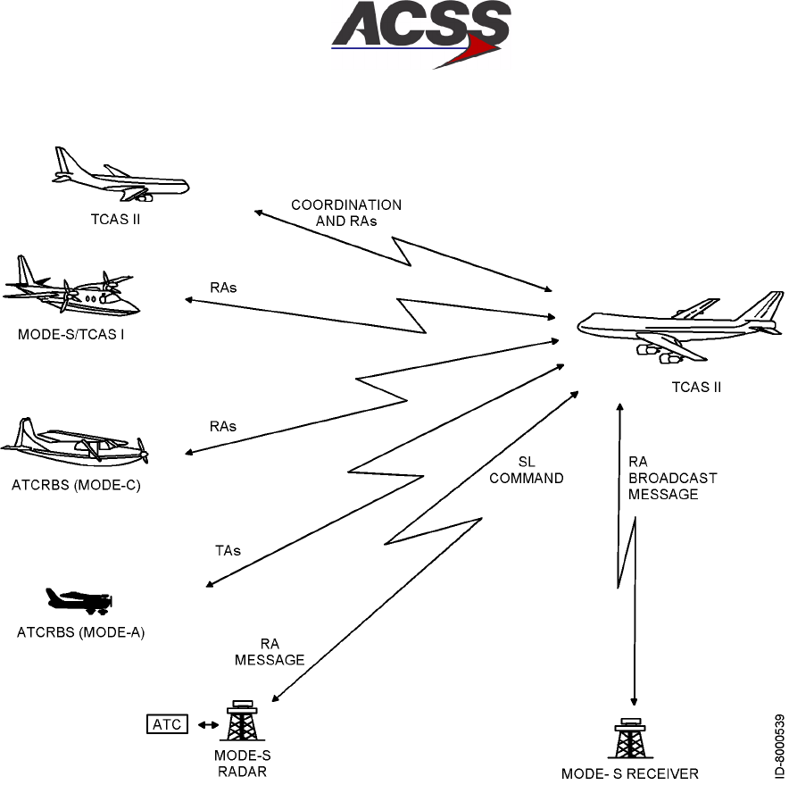
T2CAS / Part No. 9000000
SYSTEM DESCRIPTION AND INSTALLATION MANUAL
34-43-20
15 Feb 2003
Use or disclosure of information on this page is subject to the restrictions in the proprietary notice of this document.
1--8
Figure 1--1. TCAS ll Advisory Capabilities
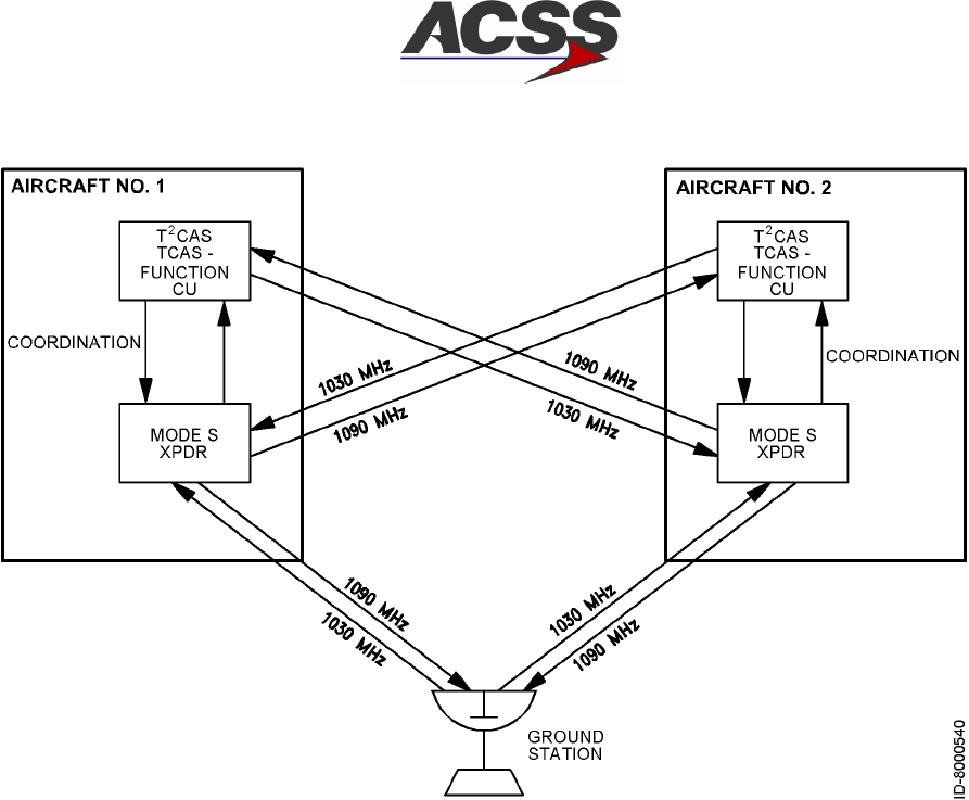
T2CAS / Part No. 9000000
SYSTEM DESCRIPTION AND INSTALLATION MANUAL
34-43-20 15 Feb 2003
Use or disclosure of information on this page is subject to the restrictions in the proprietary notice of this document.
1--9
Figure 1--2. TCAS/Mode S Communication
The TCAS function generates both RAs and TAs when the TA/RA mode is selected.
The two types of advisories correspond to time--based protection zones around the
aircraft. The airspace around the TCAS aircraft where an RA is annunciated
represents the warning area, while the larger airspace which results in a TA being
annunciated is the caution area. Figure 1--3 contrasts the airspace covered by the
two types of advisories.
The onboard equipment listed below must be linked to the TCAS function as shown
in Figure 1--4.
•Mode S transponder with associated antennas
•Radio altimeter
•Air Data Computer (ADC) (digital or analog). If an ADC does not support vertical
speed rate data, the static line can be run directly into the Thales VSI/TRA.
•ATC/TCAS control panel. A separate control panel is not the only method of
control for the TCAS. Other components, such as a Radio Management Unit
(RMU) can be used.
•Omnidirectional antenna. The TCAS function accepts two types of bottom
antennas: A standard directional antenna or an optional ATC--type
omnidirectional antenna. If an omnidirectional antenna is installed, it must be
supplied by the installer. If a directional antenna is installed at both top and
bottom antenna locations, a bottom omnidirectional antenna is not needed.
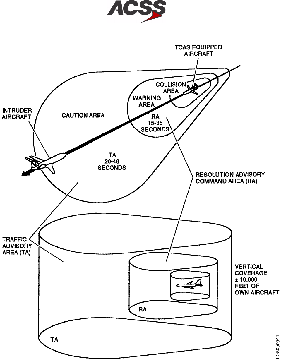
T2CAS / Part No. 9000000
SYSTEM DESCRIPTION AND INSTALLATION MANUAL
34-43-20
15 Feb 2003
Use or disclosure of information on this page is subject to the restrictions in the proprietary notice of this document.
1--10
Figure 1--3. TA/RA Airspace Coverage
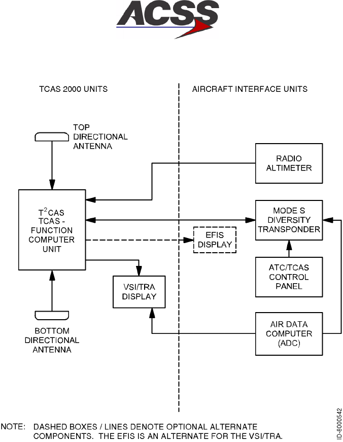
T2CAS / Part No. 9000000
SYSTEM DESCRIPTION AND INSTALLATION MANUAL
34-43-20 15 Feb 2003
Use or disclosure of information on this page is subject to the restrictions in the proprietary notice of this document.
1--11
Figure 1--4. Basic TCAS ll Installation
(2) TAWS Functional Description
The T2CAS TAWS function provides guidance to prevent Controlled Flight Into
Terrain (CFIT). This is accomplished by using vertical speed, ground speed, track
angle, flight path angle, latitude, longitude, flap status, steep approach status, static
air temperature, roll angle, pressure altitude and radio altitude inputs along with a
built--in database for determination of alerts and display of terrain information.
The following advanced functional capabilities are featured in the T2CAS TAWS
function.
(a) Collision Prediction and Alerting (CPA) Mode
This mode provides medium--term (caution) and short--term (warning) alerts
when the predicted flight path will bring the aircraft dangerously close to nearby
terrain. When operative, CPA replaces RTCA DO--161A reactive modes 1 and 2
since it offers superior safety margins for CFIT prevention due to its predictive
capabilities.

T2CAS / Part No. 9000000
SYSTEM DESCRIPTION AND INSTALLATION MANUAL
34-43-20
15 Feb 2003
Use or disclosure of information on this page is subject to the restrictions in the proprietary notice of this document.
1--12
T2CAS uses data provided by the Flight Management Computer, the GPS
receiver, and other aircraft subsystems to predict a 3--D flight path based upon a
curve--fit extrapolation of the most recent position and velocity data received.
This predicted flight path is then compared with the internal terrain map of the
immediate area and an assessment of the potential threat of aircraft collision with
terrain is computed by the Collision Prediction and Alerting (CPA) algorithm.
(b) Conventional GPWS Modes of Operation.
1Mode 1: Excessive rate of descent with respect to terrain
When the CPA mode is inoperative, this mode provides not only a reactive
short--term warning as defined in RTCA DO--161A, but also a reactive
medium--term caution when the current flight path is descending toward the
terrain ahead of the aircraft at an excessive rate.
2Mode 2: Excessive closure rate to terrain
When the CPA mode is not operative, this mode provides a reactive
short--term warning as defined in RTCA DO--161A when the current flight
path and the terrain ahead of the aircraft are closing at an excessive rate.
3Mode 3: Excessive altitude loss after take--off
T2CAS meets the requirement for Mode 3 alerts as defined in RTCA
DO--161A. This mode provides an alert when there is a loss of altitude after
take--off or during a missed approach. The mode uses the radar altimeter to
determine proximity to the ground and the barometric altimeter to determine
altitude loss. If an excessive loss of altitude occurs after take--off, a warning
is issued.
4Mode 4: Incorrect aircraft configuration with regard to terrain
T2CAS meets the requirement for Mode 4 alerts as defined in RTCA
DO--161A. Mode 4 usually applies during the landing phase of flight and
results in the annunciation of an alert in the event of insufficient terrain
clearance when the aircraft is not in the proper landing configuration. Mode
4 consists of the following two submodes:
•Mode 4A, when the landing gear is up
•Mode 4B, when the landing gear is down, but the flaps are not in landing
configuration.
5Mode 5: Excessive glide path deviation
T2CAS meets the requirement for Mode 5 alerts as defined in RTCA
DO--161A. Mode 5 applies in the event of an excessive descent below the
instrument glide path when making a front--course approach with the gear
down. In a back--course landing configuration, Mode 5 is automatically
inhibited.

T2CAS / Part No. 9000000
SYSTEM DESCRIPTION AND INSTALLATION MANUAL
34-43-20 15 Feb 2003
Use or disclosure of information on this page is subject to the restrictions in the proprietary notice of this document.
1--13
6Call--outs and excessive bank angle
As defined in RTCA DO--161A, T2CAS produces call--outs and alerts for
descent below a set of predefined altitudes and for excessive bank angle.
(c) Terrain Display
The T2CAS TAWS function provides two outputs to ARINC 708A compatible
displays to provide terrain--related information to the crew through the weather
radar or EFIS displays in order to enhance flight crew situational awareness.
When no threat is perceived, the TAWS display shows with different levels of
colors, the height of the surrounding terrain relative to the aircraft altitude and
taking into account the aircraft flight path angle. Upon detection of a potential
CFIT threat, the terrain texture is modified on the terrain map in order to identify
the location and level (caution/warning) of the threat.
(3) RWS Functional Description
T2CAS may incorporate optionally a Reactive Windshear feature as part of its basic
functionality. This feature conforms to the Windshear Warning capabilities described
in TSO C117a without the guidance feature. The reactive Windshear Warning
algorithm continuously monitors wind factors that affect aircraft performance on both
take--off and landing approach, in order to identify the presence of a severe
low--level, downburst/microburst--type windshear.
If these wind factors cause aircraft performance to decrease to a predetermined
level, an audio warning is sounded, indicating to the crew that the aircraft net
performance capability is deteriorating and rapidly approaching a critical state. In
addition to the warning, the Windshear Warning algorithm provides a caution when
an increasing--performance Windshear is detected, thus giving advance warning of
decreasing--performance windshear.
(4) GPS Functional Description
The T2CAS may optionally incorporate a Global Positioning System (GPS) receiver.
The GPS receiver is a CCA that is independent of both TCAS and TAWS/RWS, and
has an independent processor and I/O circuitry. The GPS receiver is manufactured
and supplied to ACSS by CMC Electronics. The GPS receiver is capable of providing
position information to the T2CAS as well as to other aircraft systems.
B. System Configurations
The T2CAS may be installed in different aircraft configurations depending on the current
TCAS, TAWS/RWS and GPS equipment installed on the aircraft. The T2CAS uses an
Airplane Personality Module (APM) to hold aircraft specific configuration data for TAWS
and RWS functions. The APM is used in place of program pin inputs to provide system
configuration. An Aircraft Specific Database (ASDB) provides the aircraft specific
interface requirements for the T2CAS System and is loaded into the APM at the time of
system installation.

T2CAS / Part No. 9000000
SYSTEM DESCRIPTION AND INSTALLATION MANUAL
34-43-20
15 Feb 2003
Use or disclosure of information on this page is subject to the restrictions in the proprietary notice of this document.
1--14
Further breakdown of the TCAS and TAWS/RWS system configurations are detailed in
the sections 1 and 2 that follow.
(1) TCAS System Configuration
The T2CAS unit’s TCAS function may be installed in several different configurations
depending on the transponders used and the choice of antennas and displays.
Some typical configurations are shown in Figure 1--5. Other combinations are
feasible. Figure 1--7 shows the signals and overall interconnects for a typical T2CAS
installation with dual transponders.
•Configuration A shows the TCAS function linked to dual Mode S transponders.
The system operates with either transponder, depending on the control panel
selection. The second transponder is used as a backup.
•Configuration B shows the TCAS function linked to a single transponder Mode S
transponder system.
•Configuration C shows the TCAS function to a single Mode S transponder (active)
and an ATCRBS transponder (backup). The TCAS only operates when the Mode
S transponder is selected.
(2) TAWS/RWS System Configuration
Figure 1--6 illustrates a typical aircraft installation of the T2CAS. The system is
designed as an integrated safety solution, available as a replacement to the existing
TCAS 2000 LRU. Figure 1--7 is a TCAS Function System block diagram.
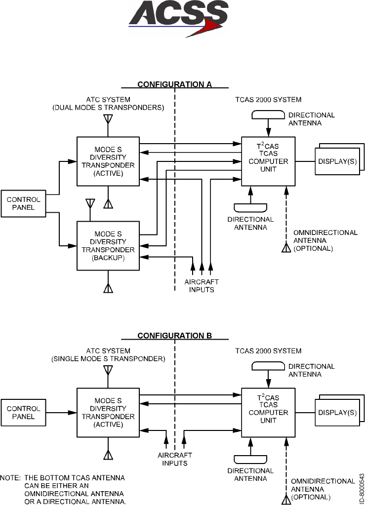
T2CAS / Part No. 9000000
SYSTEM DESCRIPTION AND INSTALLATION MANUAL
34-43-20 15 Feb 2003
Use or disclosure of information on this page is subject to the restrictions in the proprietary notice of this document.
1--15
Figure 1--5 (Sheet 1). Typical System Configurations
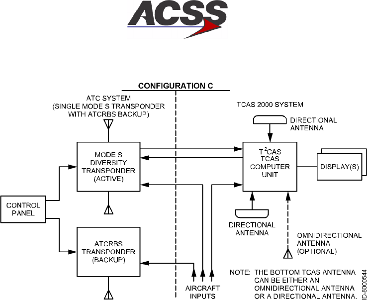
T2CAS / Part No. 9000000
SYSTEM DESCRIPTION AND INSTALLATION MANUAL
34-43-20
15 Feb 2003
Use or disclosure of information on this page is subject to the restrictions in the proprietary notice of this document.
1--16
Figure 1--5 (Sheet 2). Typical System Configurations
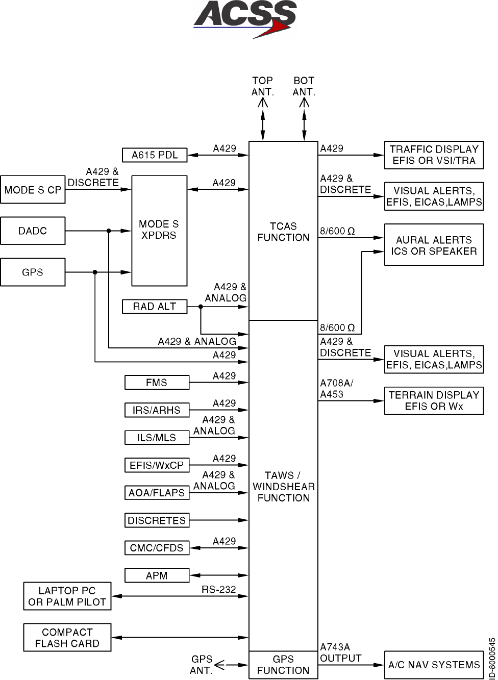
T2CAS / Part No. 9000000
SYSTEM DESCRIPTION AND INSTALLATION MANUAL
34-43-20 15 Feb 2003
Use or disclosure of information on this page is subject to the restrictions in the proprietary notice of this document.
1--17
Figure 1--6. T2CAS System Aircraft Interface

T2CAS / Part No. 9000000
SYSTEM DESCRIPTION AND INSTALLATION MANUAL
34-43-20
15 Feb 2003
Use or disclosure of information on this page is subject to the restrictions in the proprietary notice of this document.
1--18
Blank Page
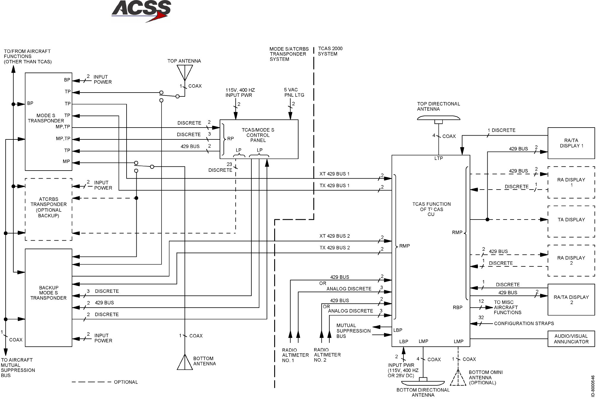
T2CAS / Part No. 9000000
SYSTEM DESCRIPTION AND INSTALLATION MANUAL
34-43-20 15 Feb 2003
Use or disclosure of information on this page is subject to the restrictions in the proprietary notice of this document.
1--19/(1--20 blank)
Figure 1--7. TCAS Function System Block Diagram

T2CAS / Part No. 9000000
SYSTEM DESCRIPTION AND INSTALLATION MANUAL
34-43-20 15 Feb 2003
Use or disclosure of information on this page is subject to the restrictions in the proprietary notice of this document.
1--21
4. Component Descriptions
A. TT--950/951/952 T2CAS Computer Unit
The T2CAS Computer Unit (CU) is the heart of the T2CAS system consisting of an
existing TCAS 2000 LRU with a TAWS/Reactive Windshear function implemented on a
separate circuit card assembly (CCA). The TAWS/RWS function uses a processor and I/O
circuitry that is independent from the TCAS function’s processor and I/O. As such, the
software programs for TCAS and TAWS/RWS are independent from each other. By
having independent hardware, I/O and software for TCAS and TAWS/RWS, the possibility
of a common mode failure causing the loss of both functions is significantly reduced.
The TCAS function (CCA) contains the RF transmitter and the receivers necessary to
interrogate and receive replies from other transponder equipped aircraft. Dual
microprocessors are utilized to implement the surveillance and collision avoidance
algorithms. The algorithms determine whether an intruder aircraft should be considered a
threat and then determine the appropriate vertical response to avoid a midair or near
midair collision. In addition, output data is provided to drive displays that inform the flight
crew what action to take or avoid.
The TCAS function also provides an interface to the onboard Mode S transponder in
order to communicate with other TCAS ll equipped aircraft in the airspace.
The TAWS/RWS function (CCA) consists primarily of the Ground Collision Avoidance
Module (GCAM). The GCAM contains the core TAWS/Windshear algorithms which utilize
A/C state data, performance database variables and Terrain/Airport database information
to calculate required TAWS/Windshear alarms, build a terrain display buffer, and then
pass the data back to the platform. The resulting terrain information is then output to
ARINC 708A compatible weather radar or EFIS displays.
The T2CAS CU also provides past and present LRU and system status through the front
panel mounted TEST switch and PASS/FAIL annunciators. Software updates can be
incorporated into the computer by an ARINC 603 or 615 data loader port through either
the connector mounted on the front panel of the computer or the port provided on the
LRU rear connector.
Figure 1--8 shows a graphical view of the TT--950/TT--952 T2CAS Computer Unit and the
TT--951 T2CAS Computer Unit. Table 1--6 provides the leading particulars.

T2CAS / Part No. 9000000
SYSTEM DESCRIPTION AND INSTALLATION MANUAL
34-43-20
15 Feb 2003
Use or disclosure of information on this page is subject to the restrictions in the proprietary notice of this document.
1--22
Figure 1--8. TT--950/TT--952 T2CAS Computer Unit (TT--951 Similar)

T2CAS / Part No. 9000000
SYSTEM DESCRIPTION AND INSTALLATION MANUAL
34-43-20 15 Feb 2003
Use or disclosure of information on this page is subject to the restrictions in the proprietary notice of this document.
1--23
Table 1--6. TT--950/951/952 T2CAS Computer Unit Leading Particulars
Item Specification
Dimensions (maximum):
•Height ....................................... 7.64 in. (194.0 mm)
•Width (TT--950/TT--952) ........................ 7.52 in. (191.0 mm)
•Width (TT--951) ............................... 4.90 in. (124.5 mm)
•Length ....................................... 15.26 in. (387.6 mm)
Weight (maximum):
•TT--950 ...................................... 17.60 lb (8.0 kg)
•TT--951 ...................................... 15.40 lb (7.0 kg)
•TT--952 ...................................... 18.60 lb (8.45 kg)
Operating Voltage:
•dcVoltage.................................... +20.5 V dc minimum, +27.5 V dc
nominal, +32.2 V dc maximum
•ac Voltage (TT--950/TT--952 only) ............... 97 V rms minimum, 115 V rms nominal,
134 V rms maximum at 400 ¦80 Hz
Power Consumption (TT--950/TT--951) ............. 70 Watts standby, 100 Watts operational
Power Consumption (TT--952) .................... 83 Watts standby, 113 Watts operational
Circuit Breaker Ratings:
•115VacCircuitBreaker ....................... 5 Amp Typical
•28VdcCircuitBreaker ........................ 10 Amp Typical
Mating Connector:
•P1 (Rear Connector) ........................... Radiall Part No. 620--800--066
•J1 (Front Connector) .......................... ACSS Part No. 4004295--160,
ITT Part No. KJ6F18A53P
Cooling Requirements:
•6 MCU Units (TT--950/952):
-- Cooling Requirements ....................... ARINC 600 (blow through) or ARINC
404 (draw through)
-- MinimumCoolingAirflowRate ................ 54.7 pounds/hour (24.86 Kg/hour)
-- PressureDrop(atminairflowrate) ............ 0.2 ±0.12 inches (5 ±3 millimeters) of
water
•4 MCU Units (TT--951):
-- Cooling Requirements ....................... NONE -- Unit has an internal fan for
cooling. No forced air cooling is required
or accepted.
-- FanOn(controlledbytemperaturesensor) ..... Temp sensor > +45 Deg C

T2CAS / Part No. 9000000
SYSTEM DESCRIPTION AND INSTALLATION MANUAL
34-43-20
15 Feb 2003
Use or disclosure of information on this page is subject to the restrictions in the proprietary notice of this document.
1--24
Table 1--6. TT--950/951/952 T2CAS Computer Unit Leading Particulars (cont)
Item Specification
-- FanOff(controlledbytemperaturesensor) ..... Temp sensor < +25 Deg C
Mounting:
•TT--950/TT--952 ............................... ARINC 600 6--MCU Tray Assembly
•TT--951 ...................................... ARINC 600 4--MCU Tray Assembly
TSO:
AllUnits(TCAS/TAWS) ..........................
All Units (with Reactive Windshear) ................
TT--952(withGPS) .............................
C119b (with deviation)2, C151A
C117A
C129A
SoftwareDevelopmentSpecification ............... DO--178B, Level B
Environmental Specifications (TT--950/--952) ........ DO--160D (with deviation)1
Environmental Category [(A2)(F2)Y]BBB
[(HBR)(RB1)(SM)]EXXXXXZ[EBZ]A
[EZ]Z[RR]M[A3E3]XXA
Environmental Specifications (TT--951) ............. DO--160D (with deviation)1
Environmental Category [(A2)(F2)X]BBB
[(HBR)(RB1)(SM)]EXXXXXZ[BZ]AZZ[R
R]M[A3E3]XXA
•Temperature / Altitude [A2F2]:
-- OperatingTemperature ...................... --55 to +70 degrees C
-- Ground Survival Temperature ................ --55 to +85 degrees C
-- Altitude .................................... Sea Level to 55,000 feet
-- LossofCooling ............................. +40 degrees C for 300 minutes minimum
RF Transmitter Characteristics:
•Transmitter Frequency ......................... 1030 ±0.01 MHz
•RF Peak Output Power:
-- Minimum................................... 53.3 dBm (210 Watts)
-- Nominal ................................... 55.3 dBm (335 Watts)
-- Maximum .................................. 57.3 dBm (540 Watts)
•UnwantedOutputPowerinanInactiveState...... --72 dBm

T2CAS / Part No. 9000000
SYSTEM DESCRIPTION AND INSTALLATION MANUAL
34-43-20 15 Feb 2003
Use or disclosure of information on this page is subject to the restrictions in the proprietary notice of this document.
1--25
Table 1--6. TT--950/951/952 T2CAS Computer Unit Leading Particulars (cont)
Item Specification
•Pulse Timing Characteristics:
-- PulseRiseTime ............................ 0.05 to 0.10 microseconds
-- PulseFallTime ............................. 0.05 to 0.20 microseconds
-- ATCRBS S1,P1,P3,P4Duration ............ 0.08 ±0.05 microseconds
-- ModeSP1,P2Duration ..................... 0.08 ±0.05 microseconds
-- ModeSP6Duration ........................ 16.25 ±0.125 microseconds (short)
30.25 ±0.125 microseconds (long)
•Whisper--Shout Characteristics:
-- Range ..................................... 0 to 26 dB attenuation by 1 dB steps
-- AbsoluteTolerance .......................... Relative to the 0 dB step, the attenuation
of each step does not exceed the
nominal attenuation by more than ±2dB
-- RelativeTolerance .......................... Step increments are ±0.5 dB and
monotonic
RF Receiver Characteristics:
•Receiver Frequency Range ..................... 1087 to 1093 MHz
•Receiver MTL Over Frequency ..................
(Normal Operation)
-- 7 7 ±2dBm (≥90% Mode S and
ATCRBS replies decoded)
•Receiver Dynamic Range ......................
(Normal Operation)
--77 to --23 dBm (≥99% Mode S and
ATCRBS replies for signal levels greater
thanMTL+3dB)
•Extended Range Reception Capability ...........
(Optional Mode)
-- 8 2 ±2dBm (≥90% Mode S squitter
replies decoded)
•Low Level Receiver Signal Rejection .............
(Normal Operation)
--81 dBm (≤10% Mode S and ATCRBS
replies decoded)
•Receiver Signal Processing ..................... Amplitude Mono--pulse
•SystemBearingAccuracy ...................... Error less than 9 degrees RMS, 27
degrees peak from --10 to +10 degrees
elevation
NOTES:
1. The TCAS--II function within the unit meets all DO--160D Environmental
Requirements except for RF Radiated Emissions, Category M (DO--160D para.
21.4) in the frequency ranges 100--150MHz and 1215--6000MHz. In these
frequency ranges it meets the requirements for RF Radiated Emissions of
DO--160C, Category Z. The unit was tested to DO--160D change 1 test
procedures.
2. The TCAS--II function within the unit has 2 FAA approved software deviations. The
deviations do not affect the installation or performance of the system. The details of the
deviations will be furnished by ACSS upon request by the customer.

T2CAS / Part No. 9000000
SYSTEM DESCRIPTION AND INSTALLATION MANUAL
34-43-20
15 Feb 2003
Use or disclosure of information on this page is subject to the restrictions in the proprietary notice of this document.
1--26
(1) System Interfaces
The T2CAS Computer Unit supports the external system interfaces that follow.
Unless otherwise specified, the specifications apply to both the TT--950/TT--952
(6--MCU) and TT--951 (4--MCU) computers. All interfaces are per ARINC 735A.
(a) Common System Interfaces
This section defines external system interfaces that are common to both the
TCAS function and TAWS/RWS function
1Radio Altimeter Interface
The T2CAS Computer Unit accepts either analog or digital radio altimeter
inputs. For each type of input, dual input ports are provided. The external
connector pins for Analog/Digital Radio Altitude Inputs #1 and #2 are shared
by TCAS and TAWS/RWS, which both have independent circuitry.
The T2CAS CU analog radio altimeter interface accepts either ARINC 552A,
Collins BCA analog input, or metric analog input formats. The T2CAS CU
also accepts additional radio altimeter inputs that meet the minimum TAWS
input signal requirements. The type of input format is selected by program
discrete inputs RMP--12B, --12H, --12J, and --12K. Each analog input
contains a valid discrete used to validate the analog input.
Each of the military radio altimeter types provide two outputs that are
connected to the T2CAS CU input pins. The two altimeter outputs are the
Analog Data Output and Analog Data Reliability signal. The T2CAS CU
uses the Data Reliability signal in conjunction with the Analog Data Output to
determine radio altimeter failures.
A condition exists for several military radio altimeters known as Out of Track.
This condition occurs when the radio altimeter has not failed and the
altimeter is not reading a valid altitude. Altitude data for an Out of Track
condition should be considered invalid and not used.
The digital radio altimeter interface accepts inputs from an ARINC 707 radio
altimeter on ARINC 429 low speed input buses.

T2CAS / Part No. 9000000
SYSTEM DESCRIPTION AND INSTALLATION MANUAL
34-43-20 15 Feb 2003
Use or disclosure of information on this page is subject to the restrictions in the proprietary notice of this document.
1--27
(b) TCAS System Interfaces
1Mode S Transponder Interface
The T2CAS computer contains two sets of ARINC 429 high speed buses for
communication with two Mode S transponders. It uses ARINC 718A/735A
communication protocol (2 inputs, 2 outputs).
2Onboard Maintenance System Interface
The TCAS function contains a set of ARINC 429 low speed buses for
communication with an onboard maintenance system (1 input, 1 output).
The unit interfaces with all major airframe manufacturers maintenance
computer systems. Since the maintenance computer protocol for each
airframe manufacturer is different, the TCAS function automatically detects
the type of airframe from the data received from the maintenance computer
and sets its protocol accordingly.
3Data Loader Interface
The TCAS function contains a set of ARINC 429 buses and discrete inputs
that interface to either an airborne data loader (ADL) through pins on the
rear connector, or a portable data loader (PDL) through the 53--pin circular
connector on the front panel of the unit. The computer works with ARINC
603 data loader protocol (low speed bus) or ARINC 615 data loader protocol
(high speed bus). The ADL and PDL ARINC 429 inputs have separate data
loader buses to allow for connection of both types of data loaders. It also
has separate data loader enable discrete inputs. The type of data loader
protocol (603 or 615) is selected by a discrete input. The unit software part
number can be output on the data loader port by grounding a discrete input.
The aural voice commands are contained in Flash Erasable Programmable
Read--Only Memory (EPROM) on the TCAS. Each software load contains in
addition to program code, voice command data. Changes to voice
commands can be made through a software load instead of removal of the
LRU from the aircraft for hardware modification.
4TCAS Display Bus Interface
The TCAS function has four sets of ARINC output buses for display of traffic
and resolution advisories.
The TA/RA Display No. 1 and No. 2 buses are high speed ARINC 429 buses
that contain both traffic information and resolution advisory information. The
buses function according to either the ARINC 735A characteristics, or can
optionally be set for the Honeywell EFIS characteristics through a program
input pin (RMP--12C). For each bus, a valid discrete input is provided that
indicates whether the display is functional.
The RA Display No. 1 and No. 2 buses are low speed ARINC 429 buses that
contain only resolution advisory information. The buses function according
to the ARINC 735A characteristics. For each bus, a valid discrete is
provided that indicates whether the display is functional.

T2CAS / Part No. 9000000
SYSTEM DESCRIPTION AND INSTALLATION MANUAL
34-43-20
15 Feb 2003
Use or disclosure of information on this page is subject to the restrictions in the proprietary notice of this document.
1--28
The RA Display No. 1 and No. 2 buses can be configured for a 429 Data
Recorder function by grounding programming pin (RMP--11D). In this mode,
the buses are configured for high speed operation.
5Performance Management Bus Interface
The TCAS function contains a low speed ARINC 429 bus input (RMP--6A,
6B) that is reserved for connection to a performance management system.
The input is provisioned to obtain maximum rate of climb information from a
FMS or Performance Management System (PMS.) The input is provided for
future system enhancements and is currently not used.
6Magnetic Heading/Attitude Bus Interface
The TCAS function contains a high speed ARINC 429 bus input (RMP--7A,
7B) reserved for connection to an Inertial Reference System (IRS) or
Attitude Heading and Reference System (AHRS). The input lets aircraft
heading and attitude data be input for the purpose of providing for future
horizontal maneuvers. This function has not been implemented on TCAS II
installations, so these pins are reserved for future use.
7RS--422 Data Recorder Interface
The TCAS function contains an RS--422 interface connected to a data
recorder. The interface consists of two RS--422 input buses and two
RS--422 output buses, with a program input to select internal or external
clock operation. The RS--422 input buses input a reply enable signal and an
external recorder clock. The RS--422 output buses output the recorder data
and internal 125 KHz clock reference. The interface also contains a
program pin for enabling or disabling the data recorder function. The
RS--422 data recorder inputs and outputs are connected to pins on the front
panel 53--pin PDL connector.
8ARINC 573 Flight Data Recorder Interface
The TCAS function contains 12 discrete outputs connected to an ARINC
573 flight data recorder. The outputs are used to record information during a
resolution advisory event.
9ARINC 429 Flight Data Recorder Interface
The TCAS function contains an interface for an ARINC 429 flight data
recorder. The flight data recorder function is activated by grounding a
discrete input pin (RMP--11D) on the rear connector. With the discrete input
grounded, flight data is output as high speed ARINC 429 data on the RA
Display No. 1 and No. 2 Buses. With the discrete grounded, the normal RA
Display bus operation is not available.

T2CAS / Part No. 9000000
SYSTEM DESCRIPTION AND INSTALLATION MANUAL
34-43-20 15 Feb 2003
Use or disclosure of information on this page is subject to the restrictions in the proprietary notice of this document.
1--29
10 Voice Audio Outputs
The TCAS function contains two analog audio outputs that provide TCAS
aural traffic advisories and resolution advisories. The 8--ohm output has the
capability to supply up to 8 Watts RMS into a speaker. The 600--ohm output
has the capability to supply up to 80 milliwatts RMS into an audio distribution
system.
11 RS--232 Interface
The TCAS function has an RS--232 input/output for connection to a personal
computer. The interface allows for LRU maintenance and troubleshooting.
The maintenance log and RA event log can also be downloaded to a PC
using this port. The RS--232 interface is connected to the 53--pin PDL
connector on the front of the unit.
12 Altitude Alerter Interface
The TCAS function contains an ARINC 429 low speed input bus that is
reserved for receiving selected altitude information from an altitude control
source or flight control computer. The TCAS function uses the selected
altitude information to inhibit the weakening of a resolution advisory by
determining the selected altitude limits for the aircraft.
13 Reserved ARINC 429 Bus Interface
The TCAS function has four sets of reserved ARINC 429 input buses
configured as either high speed or low speed. These buses allow for future
upgrades to the TCAS system without hardware modification.
(c) TAWS/RWS System Interfaces
1Onboard Maintenance System Interface
The TAWS/RWS function contains a set ASDB defined ARINC 429 low
speed buses for communication with an onboard maintenance system (1
input, 1 output). The unit interfaces with all major airframe manufacturers
maintenance computer systems. Since the maintenance computer protocol
for each airframe manufacturer is different, the T2CAS computer uses
information from the Aircraft Personality Module (APM) to determine what
OMS system, if any, is installed.
2Data Loader Interface
The TAWS/RWS function is provisioned for interface with an ARINC 615A
data loader (Ethernet 10 Base--T). The front Portable Data Loader
connector contains the signals required by the ARINC 615A specification.
The interface will be used to upload future software updates to the
TAWS/RWS system.

T2CAS / Part No. 9000000
SYSTEM DESCRIPTION AND INSTALLATION MANUAL
34-43-20
15 Feb 2003
Use or disclosure of information on this page is subject to the restrictions in the proprietary notice of this document.
1--30
The T2CAS also contains an access port on the front of the unit that accepts
a Type I Compact PC Flash card. The Compact PC card is commercially
available and can hold up to 300 Megabytes of memory. The Compact PC
card is electrically compatible with PCMCIA Flash cards and can be inserted
in a PCMCIA card slot on a PC using an adapter, or a USB serial port with
an adapter. The Compact PC Flash card is used for updating the
TAWS/RWS operational software and terrain database. In addition, the
Compact PC Flash card may be used as a data recorder for the purpose of
certification flight tests. T2CAS is designed so the Compact PC card may
remain inserted in the unit during flight tests.
3TAWS Display interface
The TAWS function contains two Digital 453 picture bus outputs that transmit
terrain display data to ARINC 708A compatible weather radar displays or
EFIS displays. The bus outputs can be configured with independent range
selections. The Mode and Range selections are input to the system on an
ARINC 429 bus.
The TAWS function also has two ARINC 429 bus outputs that contain data
for alerts and annunciation of system status.
4RS--232/ Compact Flash Card Data Recorder Interface
The Data Recorder Interface can utilized for either internal or external Data
recording.
The TAWS/RWS Event log contains event information due to TAWS or
Windshear cautions or warnings (internal Data recording). The log can hold
approximately three events that last up to 45 seconds each (assuming
GCAM Event, GCAM Parameter data and GFM parameter data selected for
recording). The event log data may be downloaded to a Laptop PC over the
RS--232 port, or downloaded to a Compact Flash card using the slot on the
front of the unit.
The external Data recording provides the capability to perform real--time
recording of various T2CAS input, output and internal data. This data may
be recorded using the Compact Flash Card or RS--232 interface. Using a
300Mbyte Compact Flash card, the system can store up to 15 hours of flight
test data.
In addition, the RS--232 interface allows for LRU maintenance and
troubleshooting. The maintenance log and RA event log can also be
downloaded to a PC using this port. The RS--232 interface is connected to
the 53--pin PDL connector on the front of the unit.

T2CAS / Part No. 9000000
SYSTEM DESCRIPTION AND INSTALLATION MANUAL
34-43-20 15 Feb 2003
Use or disclosure of information on this page is subject to the restrictions in the proprietary notice of this document.
1--31
5Flight Data Recording
There is currently no output to the Flight Data Recorder.
6Voice Audio Outputs
The TAWS/RWS function contains two analog audio outputs that provide
TAWS/RWS aural terrain avoidance advisories and windshear advisories.
The 8--Ohm output has the capability to supply up to 8 Watts RMS into a
speaker. The 600--Ohm output has the capability to supply up to 80
milliwatts RMS into an audio distribution system.
7Air Data Interface
The TAWS/RWS function uses Vertical Speed, Static Air Temperature,
Computed Air Speed, Corrected/Uncorrected Barometric Altitude from an air
data system. In addition, TAWS/RWS uses True Airspeed (TAS) on
installations where T2CAS is performing the RWS function.
The TAWS/RWS function accepts up to two Digital ARINC 429 inputs from
Digital Air Data Systems. Some of the supported system interfaces include
ARINC 706 Air Data Computer (ADC), ARINC 575 ADC, ARINC 738 Air
Data Inertial Reference System (ADIRS), and other non--ARINC standard
interfaces that meet the minimum input signal requirements for TAWS/RWS.
TAWS/RWS can accept analog air data inputs from an ARINC 565 or ARINC
575 Air Data System and other non--ARINC standard interfaces. Analog
system inputs can be in the form of 2--wire DC absolute, 2--wire DC
ratio--metric, 2--Wire AC ratio--metric, 3--Wire AC Synchro, 3--Wire AC
Sine/Cosine.
8Inertial Reference Interface
TAWS/RWS function uses Ground Speed, True Track Angle, Flight Path
Angle, Latitude, Longitude, Altitude MSL, Roll Angle, Pitch Angle, Inertial
Vertical Speed, and True Heading from an inertial system.
Additionally, TAWS/RWS uses Body Longitudinal and Normal Acceleration
on installations where TAWS/RWS is performing the RWS function.
TAWS/RWS accepts up to two Digital ARINC 429 inputs from an ARINC 704
Inertial Reference System (IRS), ARINC 705 Attitude Heading and
Reference System (AHRS), ARINC 738 Air Data Inertial Reference System
(ADIRS), Global Positioning and Inertial Reference System (GPIRS) and
other non--ARINC standard interfaces that meet the minimum input signal
requirements for TAWS/RWS.
TAWS/RWS can accept analog inputs for Body Longitudinal and Normal
Acceleration, Pitch and Roll, Magnetic Track, Variation and Heading. The
analog input sources can be 2--Wire DC Absolute and 3--Wire AC Synchro.

T2CAS / Part No. 9000000
SYSTEM DESCRIPTION AND INSTALLATION MANUAL
34-43-20
15 Feb 2003
Use or disclosure of information on this page is subject to the restrictions in the proprietary notice of this document.
1--32
9FMC Interface
The TAWS/RWS function uses Ground Speed, True Track Angle, Flight Path
Angle, Aircraft Weight, Latitude, Longitude and True Heading from an FMC
system.
TAWS/RWS can accept up to two Digital ARINC 429 inputs from an ARINC
702 Flight Management Computer system or other non--ARINC standard
interfaces.
10 GPS/GNSS
The TAWS/RWS function uses Vertical Speed, Ground Speed, True Track
Angle, Latitude, Longitude, Altitude MSL, WGS 84 altitude and True
Heading from a GPS System.
NOTE: World Geodetic System (WGS) 84 altitude is another type of MSL
altitude.
TAWS/RWS accepts up to two Digital ARINC 429 inputs from an ARINC 743
or ARINC 743A GPS System, or other non--standard ARINC interfaces that
meet the minimum input signal requirements for TAWS/RWS
11 ILS/MLS
The TAWS/RWS function uses Selected Runway Heading, Glide Slope
Deviation, Localizer Deviation, and ILS Select from an Instrument Landing
System (ILS) or Microwave Landing System (MLS).
TAWS/RWS can accept up to three Digital ARINC 429 inputs from an ARINC
710 ILS receiver, ARINC 727 MLS receiver, or other non--ARINC standard
interfaces.
TAWS/RWS can accept up to two Analog Glide Slope and two Analog
Localizer inputs from an ARINC 547 or ARINC 578 ILS receiver as a 2--Wire
DC absolute input.
12 Angle Of Attack
On installations where T2CAS is performing the RWS function, the
TAWS/RWS function uses the aircraft angle of attack for the Windshear
computation.
TAWS/RWS can accept up to two ARINC 429 inputs from a source such as
a Digital Stall Warning Computer (DSWC) or other data concentrator
devices.
TAWS/RWS can accept analog angle of attack information in the form of
3--Wire AC Synchros, 2--Wire DC absolute and 2--Wire DC ratio--metric
inputs.

T2CAS / Part No. 9000000
SYSTEM DESCRIPTION AND INSTALLATION MANUAL
34-43-20 15 Feb 2003
Use or disclosure of information on this page is subject to the restrictions in the proprietary notice of this document.
1--33
13 Decision Height
The TAWS/RWS function uses selected Decision Height and/or Minimum
Descent Altitude for the generation of audio call--outs. TAWS/RWS can
accept ARINC 429 inputs or a discrete input.
14 Decision Height/Minimum Descent Altitude Switch
A Flight Deck switch can be used to select either Decision Height or
Minimum Descent Altitude for audio call--out altitude determination.
15 Flap/Slat Settings
TAWS/RWS function uses Flap/Slat settings for TAWS and Windshear alerts.
TAWS/RWS can accept ARINC 429 Flap/Slat Setting inputs from a source
such as a Digital Stall Warning Computer (DSWC) or other data concentrator
devices. TAWS/RWS also accepts Analog inputs in the form of 3--Wire AC
Synchros, DC absolute, DC ratio--metric and Discrete Inputs.
16 Weight and Balance System (WBS)
The TAWS/RWS function obtains Current Aircraft Weight from an A429
Digital Weight and Balance System source.
(2) Discrete Inputs
The T2CAS has various discrete inputs available for implementing various TCAS and
TAWS/RWS functions. For the TCAS function, the input logic status is defined in
accordance with ARINC 735A. For the TWAS/RWS function, the input definition is
defined by the ASDB for the specific aircraft type.
(3) Program Inputs
The T2CAS has various program inputs available for TCAS unit configuration and
installation programming. Input logic status is defined according to ARINC 735A
definition.
The T2CAS utilizes the ASDB database for TAWS/RWS unit configuration and
installation programming.
The ASDB defines the assignment of the connector pins to each signal, the criteria
for determining the value and status of each signal and the signal specific filtering
and processing requirements.
(4) Discrete Outputs
The T2CAS TAWS function contains 13 discrete outputs that are used to provide
annunciation of alerts and system status. For the TCAS function, the output logic
status is defined in accordance with ARINC 735A. For the TAWS/RWS function, the
output definition is defined by the ASDB for the specific aircraft type.

T2CAS / Part No. 9000000
SYSTEM DESCRIPTION AND INSTALLATION MANUAL
34-43-20
15 Feb 2003
Use or disclosure of information on this page is subject to the restrictions in the proprietary notice of this document.
1--34
(5) Self--Test Function
(a) TCAS and TAWS/RWS Maintenance Self--Test
By momentarily pushing the TEST switch on the front panel of the T2CAS
Computer Unit, maintenance personnel can display fault data for the current and
preceding flight legs. When TEST is initially activated, all annunciators (pass/fail
lamps on front of unit) are ON for a 3--second lamp test, then current fault data is
displayed for 10 seconds. If no further activations of the TEST switch are made,
the LRU display cycle is terminated at the end of the 10--second fault display
period, and all annunciators are extinguished.
If during the 10--second fault display period, the TEST button is activated again,
the fault display period is aborted, a 2--second lamp test cycle is done, and the
fault data recorded for the preceding flight leg is displayed for 10 seconds. This
procedure can be repeated up to 10 times to obtain recorded data from the
previous 10 flight legs. If the TEST button is not activated again during the fault
display period, the fault display cycle is terminated at the end of the 10--second
fault display period and all annunciators are extinguished. If an attempt is made
to display fault data for the preceding flight leg when the tenth preceding flight
leg fault data is displayed, all annunciators flash for a 3--second period at a
2.5--Hz rate, after which all annunciators are extinguished.
When less than 10 flight legs have been flown since the T2CAS Computer Unit
was shop tested and recertified, less than 10 previous flight legs of recorded
fault data may be available for display. In this case, if an attempt is made to
display fault data for the preceding flight leg when the earliest flight leg is
displayed, all annunciators flash for 3 seconds at a 2.5--Hz rate and then all
annunciators are extinguished.
The TCAS PASS, TCAS FAIL, and TAWS Pass/Fail status annunciators indicate
the status of the T2CAS Computer Unit only. All other annunciators reflect the
condition of the respective sub--system.
(b) TCAS Self--Test
The T2CAS TCAS self--test is initiated from a self--test button on the
TCAS/MODE S control panel. The T2CAS TCAS self--test may also be initiated
from the Central Maintenance Computer.
(c) TAWS/RWS/GPS Self--test
The T2CAS TAWS/RWS/GPS self--test is initiated from a self--test discrete input
interface. The TAWS/RWS/GPS self--test discrete is further defined in the ASDB.
The T2CAS TAWS/RWS/GPS self--test may also be initiated from the Central
Maintenance Computer.
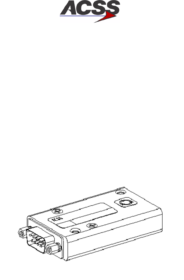
T2CAS / Part No. 9000000
SYSTEM DESCRIPTION AND INSTALLATION MANUAL
34-43-20 15 Feb 2003
Use or disclosure of information on this page is subject to the restrictions in the proprietary notice of this document.
1--35
B. Airplane Personality Module Interface
The Airplane Personality Module (APM) is defined in ARINC Report 607, Attachment 3 --
see Figure 1--9. A serial digital interface between the T2CAS Computer and the APM
allows the APM to be programmed with aircraft and system configurations during the
initial installation of the T2CAS computer. In addition, the serial digital interface allows the
APM to be read during every subsequent power--on to configure the computer for proper
operation. The APM is used to hold/provide information for the T2CAS configuration
database, for example, registration number, aircraft type, equipment installed, et cetera.
Moreover, the APM contains the Aircraft Specific Database which defines the
Input/Output definition for the specific aircraft type, the aircraft climb performance data to
support of the TAWS functionality and the windshear algorithm coefficient data.
Figure 1--9. T2CAS Airplane Personality Module (APM)
C. Directional Antenna
The T2CAS TCAS directional antenna, Figure 1--10, is a four--element, vertically
polarized, monopole array capable of transmitting in four selectable directions at 1030
MHz. The antenna is capable of receiving replies from all directions simultaneously with
bearing information at 1090 MHz, using amplitude--ratio monopulse techniques.
The antenna consists of a molded radome with radiating/receiving elements and is
completely filled with a rigid foam. The antenna assembly uses five or nine screws to
attach the radome and either four or eight screws to attach the antenna to the aircraft
fuselage.

T2CAS / Part No. 9000000
SYSTEM DESCRIPTION AND INSTALLATION MANUAL
34-43-20
15 Feb 2003
Use or disclosure of information on this page is subject to the restrictions in the proprietary notice of this document.
1--36
The ACSS directional antenna has a small frontal area. The circular radome has a 3:1
elliptical leading edge and an extremely low profile height of only 0.806 inch. This yields
excellent aerodynamic performance with a minimum possibility of icing, which could be a
hazard for rear mounted engines.
For T2CAS TCAS system installations, the top antenna must be a directional antenna.
The bottom antenna can be either a directional or omnidirectional antenna. The T2CAS
Computer Unit has the capability of automatically sensing which version is installed.
The directional antenna mounting screws are standard #10--32 UNF--2A pan head,
corrosion--resistant (stainless) steel screws in accordance with Military Specification
MS51958. The appropriate length is determined by the installer allowing 0.5--inch for the
thickness of the antenna and adapter plate. A washer must be installed under the head
of each mounting screw. The washer must be made of passivated, corrosion--resistant
steel in accordance with MIL--S--5059 or MIL--S--6721. The Air Force--Navy Aeronautical
Standard part number is AN960C10L. The washer has an outer diameter of 0.438 inch,
an inner diameter of 0.203 inch, and a thickness of 0.032 inch.
An O--ring (included with the directional antenna) is required to be installed between the
directional antenna and the aircraft fuselage. The National Aerospace Standard part
number for the O--ring is NAS 1611--240. The ACSS part number for the O--ring is
4000171--240.
NOTE: For directional antennas, ACSS Part No. 7514060--90X, the customer must
provide an adapter plate for mounting to the aircraft. For details of the antenna
base plate, to which the adapter must mate, refer to Section 2. Directional
antennas, ACSS Part No. 7514081--9XX, come with a preinstalled adapter plate.
The average unit weight of an antenna with adapter plate is approximately 3.0 pounds.
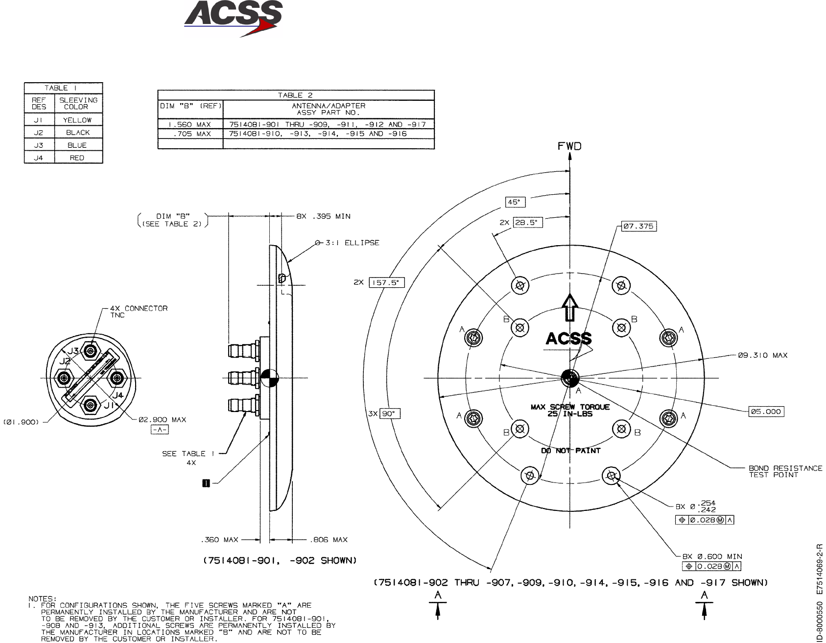
T2CAS / Part No. 9000000
SYSTEM DESCRIPTION AND INSTALLATION MANUAL
34-43-20 15 Feb 2003
Use or disclosure of information on this page is subject to the restrictions in the proprietary notice of this document.
1--37/(1--38 blank)
Figure 1--10. Directional Antenna

T2CAS / Part No. 9000000
SYSTEM DESCRIPTION AND INSTALLATION MANUAL
34-43-20 15 Feb 2003
Use or disclosure of information on this page is subject to the restrictions in the proprietary notice of this document.
1--39
D. GPS Antenna and Coax
For T2CAS installations that include the optional internal GPS module, a compatible
ARINC 743A active GPS antenna and coax interface shall be included in the T2CAS
installation design.
The antenna used for the GNSSA Receiver Module is required to meet the requirements
of RTCA/DO--228, Change 1, and TSO--C144. A potentially suitable antenna is listed
below, although antennas are available from different vendors:
•Manufacture: AeroAntenna
•Part Number: AT575--143WAC--TNCF--000--26--NM
•Description: 26 dB gain, 12 volt, Active Antenna
The range of antenna gains which are acceptable is dependent on the coax length and
resulting dBs of loss. Generally, an antenna gain of 20 -- 30 dB is desired. Higher gain
antennas introduce the amplification of noise as well as the desired signal. This can
saturate the GPS input circuitry, reducing its effectiveness. If the antenna gain is low and
the resulting limit of allowable cable loss is exceeded, excessive signal degradation will
occur and the GNSSA Receiver Module may not be able to meet its performance
specifications.
Do--228 Change 1 compliant antennas are required. Change 1 introduced rejection at 5
to 10 dB higher that the original DO--228 requirements at the SATCOM frequency.
Therefore system performance under interference can not be assured with the
non--Change 1 compliant antennas. When subjected to DO229 normal interference
levels, system performance can be degraded.
Figure 1--11 shows a typical T2CAS GPS antenna coax sub kit with the sub kit parts listed
in Table 1--7. Figure 2--4 shows AeroAntenna’s AT575--143 active GPS antenna series
outline drawing.
The GPS coax installation should include one disconnect near the T2CAS computer tray
to facilitate the removal of the equipment shelf from the aircraft. The T2CAS computer
provides +12 Vdc to the active GPS antenna through the coax’s center conductor.
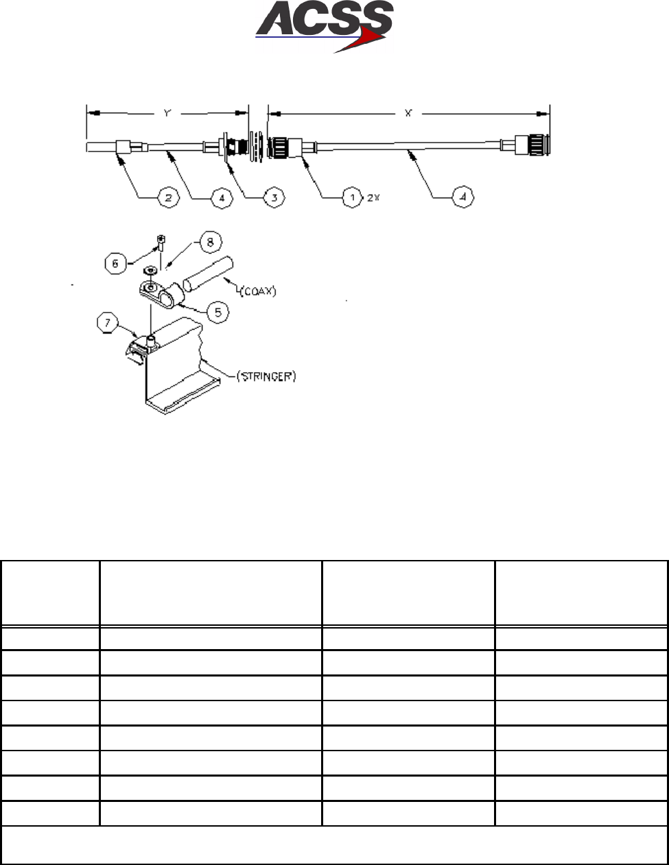
T2CAS / Part No. 9000000
SYSTEM DESCRIPTION AND INSTALLATION MANUAL
34-43-20
15 Feb 2003
Use or disclosure of information on this page is subject to the restrictions in the proprietary notice of this document.
1--40
Figure 1--11. Typical T2CAS GPS Antenna Coax Sub Kit
Table 1--7. GPS Antenna Coax Kit Parts List
Item Number
Nomenclature
or
Description Part Number Number Required
1TNC STRAIGHT PLUG See Note 2
2ARINC SIZE 5 CONTACT See Note 1
3TNC BULKHEAD JACK See Note 1
4GPS COAX See Note See Note
5CLAMP MS25281--R4 See Note
6SCREW, HEX--HD, 10--32 X .38 NAS1801--3--6 See Note
7STAND--OFF CLIP 294243--12C See Note
8WASHER #10 X .032 THK, ALUM NAS1149D0332J See Note
NOTE: The part numbers and/or quantity of listed parts are dependent on the installation
design.
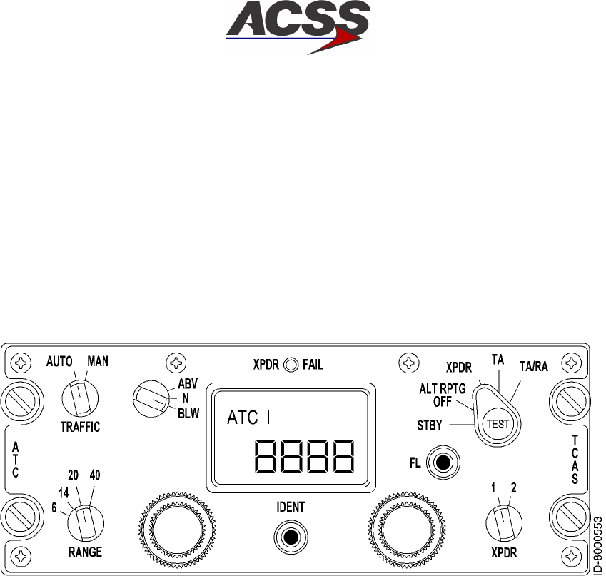
T2CAS / Part No. 9000000
SYSTEM DESCRIPTION AND INSTALLATION MANUAL
34-43-20 15 Feb 2003
Use or disclosure of information on this page is subject to the restrictions in the proprietary notice of this document.
1--41
E. Gables ATC/TCAS Dual Mode S Transponder Control Panel
The Gables ATC/TCAS Mode S control panel is used to independently control two Mode
S transponders, and to interface with a Mode S installation with TCAS capabilities.
The control panel contains two isolated electronic modules each dedicated to a given
transponder. Each module derives its input ATC code data from two dual concentric
knobs. The selected code is then displayed on a four digit Liquid Crystal Display (LCD),
and subsequently transmitted to each transponder.
Figure 1--12 shows a typical front panel layout of a Gables G7130 series control panel.
Table 1--8 gives items and specifications that are particular to these units.
Figure 1--12. Typical Gables ATC/TCAS Control Panel
T2CAS / Part No. 9000000
SYSTEM DESCRIPTION AND INSTALLATION MANUAL
34-43-20
15 Feb 2003
Use or disclosure of information on this page is subject to the restrictions in the proprietary notice of this document.
1--42
Table 1--8. Gables G7130 Series Control Panel Leading Particulars
Item Specification
Dimensions (maximum):
•Height ...................................... 2.25 in. (57.2 mm)
•Width ....................................... 5.75 in. (146.1 mm)
•Length ...................................... 5.80 in. (147.3 mm)
Weight (maximum) ............................. 2.0 lb (0.907 kg)
Power Requirements:
•Primary ..................................... +28 V dc, 0.25 Amps maximum current
•DisplayandOverlayLighting................... 5 V, 400 Hz, 2.3 Amps maximum
DisplayType................................... Four Digit, Dichroic LCD
Code Select Range ............................. 0000 to 7777 (octal)
Transmitted ARINC 429 Labels ................... 013, 015, 016, 031 (octal)
TSO .......................................... C112/C119
EnvironmentalSpecifications..................... /A2D1/BB/MB·/XXXXXXZZAZZRZ/xxZZ
Mating Connectors:
•J1 .......................................... M83723/75R16247 or MS24266R16B24S7
•J2 ......................................... M83723/75R16248 or MS24266R16B24S8
Mounting ...................................... Four Unit Dzus Fasteners
(1) Functional Description and Operation
Communication with Mode S transponders is accomplished through an ARINC 429
bus as defined in ARINC Characteristic 718. Control panel functions include 4096
ident code selection and display, altitude source and reporting inhibit selection,
selection between two onboard transponders, TCAS TA or TA/RA advisory selection,
range selection (in nautical miles) and a system functional test selection. A
description of the front panel annunciator and switch functions follows:
(a) Transponder Code Display
The control panel has a single four digit LCD display common to both modules
within the unit. The display shows the ATC code selected by the user and
consequently transmitted to the transponders. Input to the display is controlled
by the system select switch (XPDR 1--2).
In addition, certain fault indications are also indicated on the display. After a
functional test has been initiated, PASS shows on the display after a successful
test, or it shows FAIL if a high level failure is detected under normal operating
conditions. It also shows which transponder is active by displaying ATC 1 or 2.

T2CAS / Part No. 9000000
SYSTEM DESCRIPTION AND INSTALLATION MANUAL
34-43-20 15 Feb 2003
Use or disclosure of information on this page is subject to the restrictions in the proprietary notice of this document.
1--43
(b) ATC Code Selection
The ATC four digit code is selected with two dual concentric sets of knobs. Each
knob is dedicated to a single liquid crystal display (LCD) digit on the LCD code
display. The two smaller knobs control the inner digits of the LCD (tens and
hundreds) while the two larger knobs control the outer most digits (units and
thousands).
(c) XPDR 1--2 Switch
The XPDR switch is a two position switch that allows the selection of one
Mode--S module in the control panel, and the activation of its associated
transponder (System 1 or System 2).
(d) Mode Control Selector Switch
The rotary switch labeled STBY--ALT RPTG OFF--XPDR--TA ONLY--TA/RA
allows the operator to activate the TCAS system by selecting TA, or traffic and
resolution advisory (TA/RA). When STBY is selected, both transponders are
selected inactive or in standby mode. Altitude reporting off (ALT RPTG OFF)
selection disables the altitude data sources interrupting transmission of aircraft
altitude and location information to ground controllers.
(e) ABV/N/BLW Switch
The ABV/N/BLW switch selects an altitude range (from aircraft) for traffic display
on the TCAS displays. Range limits for software versions prior to Change 7 are
7000 feet above and 2700 feet below the aircraft when in ABV mode and 2700
feet above and 7000 below the aircraft when in BLW mode. Range limits for the
Change 7 software version are 9900 feet above and 2700 feet below the aircraft
when in ABV mode and 2700 feet above and 9900 below the aircraft when in
BLW mode. When the normal (N) position is selected, the display range is 2700
feet above and below the aircraft.
(f) Traffic Display Switch
The TRAFFIC AUTO--MAN switch is a two position rotary switch that controls the
TCAS traffic display mode of operation. When the AUTO mode is selected, the
TCAS computer sets the TCAS displays to pop--up mode under a
traffic/resolution advisory condition. If the MAN mode is selected, then the TCAS
displays will be constantly activated advising of any near by traffic detected
within the horizontal and vertical range limits.
(g) Range Switch
The RANGE switch is a four or six position rotary switch used to select among
different nautical mile (NM) traffic advisory horizontal range displays.

T2CAS / Part No. 9000000
SYSTEM DESCRIPTION AND INSTALLATION MANUAL
34-43-20
15 Feb 2003
Use or disclosure of information on this page is subject to the restrictions in the proprietary notice of this document.
1--44
(h) IDENT Key
The IDENT key is a momentary button. When pushed, the IDENT key causes
an ATCRBS reply or Mode S UF--4 and UF--5 replies to contain a special pulse
identifier pulse (SPI) as an identifier to be transmitted to ground controllers in
accordance with ARINC 718 Draft 5 of Supplement 4.
(i) Flight Level Button
The FL button is a momentary button used to select between relative and
absolute altitude information. When absolute is selected, this mode is enabled
for approximately 20 seconds and then reverts back to relative.
(j) Test Button
The TEST button enables the user to initiate a system functional test. When the
TEST button is pushed, the control panel initiates an internal test while a
functional test output is also transmitted through ARINC 429 labels.
When installed with a TCAS system, an extended test can be initiated by
continuously pushing the TEST button for at least eight seconds.
(k) XPDR FAIL Annunciator
The XPDR FAIL annunciator displays the functional status of the active
transponder. The fail annunciator lights only when a failed transponder is
selected on the XPDR 1--2 switch.
F. TAWS Control Panel
The TAWS controls are used to control the displayed terrain data and TAWS inhibit
features. The TAWS control panels may be installed in a single or dual configuration
depending on the TAWS display capabilities.
The TAWS controls can be mounted on a single control panel or they can be discrete
switches individually mounted at a convenient location in the Flight Deck. The TAWS
controls may be part of the electronic display menu selection in installations where TAWS
information is displayed on an EFIS or electronic display.
G. VSI/TRA Display
The VSI/TRA display, Figure 1--13, is used to display current vertical speed and TCAS
traffic/warning information. The display consists of a full color, active matrix, liquid crystal
display panel. The display quality compares favorably to CRT displays but requires less
power, weight, and volume than a CRT with a similar display area. Table 1--9 gives items
and specifications particular to the unit. Figure 1--14 contains an interface block diagram
of the 41--pin VSI/TRA.
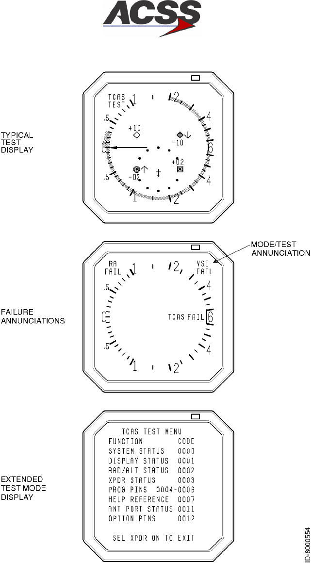
T2CAS / Part No. 9000000
SYSTEM DESCRIPTION AND INSTALLATION MANUAL
34-43-20 15 Feb 2003
Use or disclosure of information on this page is subject to the restrictions in the proprietary notice of this document.
1--45
Figure 1--13. Typical VSI/TRA Display Formats
T2CAS / Part No. 9000000
SYSTEM DESCRIPTION AND INSTALLATION MANUAL
34-43-20
15 Feb 2003
Use or disclosure of information on this page is subject to the restrictions in the proprietary notice of this document.
1--46
Table 1--9. VSI/TRA Leading Particulars
Item Specification
Dimensions (maximum):
•Height ....................................... 3.26 in. (82.8 mm)
•Width ........................................ 3.26 in. (82.8 mm)
•Length ....................................... 7.5 in. (190.0 mm)
Weight (maximum) .............................. 3.3lb(1.5kg)
Power Requirements:
•Primary ...................................... 115 V, 400 Hz; 17 Watts nominal (Day),
12 Watts nominal (Night),
20 Watts maximum
•ExternalCircuitBreakerRating.................. 1Ampat115Vac
DisplayType.................................... Liquid Crystal
Mating Connectors:
•J1(41Pin) ................................... M83723/72R--20--41--6
Mounting ....................................... 3--ATI Clamp, Marmon NH1004994--30
or MSP 64311B
(1) Functional Description and Operation
The VSI/TRA has three functions. It continuously displays rate of climb or rate of
descent. Traffic information is displayed and resolution advisory information is
displayed against vertical speed to allow the flight crew to avoid threats.
The vertical speed display is generated from signals applied directly to the indicator.
The VSI/TRA is designed to be used in place of a conventional vertical speed
indicator. Four possible sources exist for vertical speed data including ARINC 429
data, DC analog signals in accordance with ARINC 575 (approximately 500 mV per
1000 ft/min), ac analog signals in accordance with ARINC 565 (approximately 250
mV per 1000 ft/min), and ARINC 429 signals from the ACSS Pressure Transducer
Module. The VSI/TRA computes vertical rate from electrical static pressure when a
remote static sensor is used. These four program pin selectable configurations
provide compatibility with most aircraft.
Various dash number VSI/TRA Displays are available that provide unique design
characteristics, which include VSI rate filter programming and selection of an English
or metric rate scale. Table 1--5 contains a listing of all the VSI/TRA configurations.

T2CAS / Part No. 9000000
SYSTEM DESCRIPTION AND INSTALLATION MANUAL
34-43-20 15 Feb 2003
Use or disclosure of information on this page is subject to the restrictions in the proprietary notice of this document.
1--47
The VSI/TRA also displays symbology corresponding to traffic in the vicinity of the
aircraft. Threat information is received from the TCAS function on a dedicated
high--speed ARINC 429 bus. The display uses the bearing, altitude, and range data
for each threat to provide an indication of the proximity of the threat. Allowable
(nonilluminated or green illuminated bands) and prohibited (red illuminated bands)
vertical rates are displayed based on information received from the TCAS function.
The VSI/TRA can be pin programmed to provide vertical speed data only, vertical
speed and resolution advisory data, or vertical speed, resolution advisory and traffic
advisory data. Display of the TCAS system fault status is provided on the VSI/TRA in
response to extended TCAS control panel TEST activation.
Display dimming is controlled from several inputs consisting of an internal light sensor
mounted on the bezel of the LRU, a remote light sensor, and the aircraft dimming
bus. The display is dimmed by varying the brightness of the LCD panel backlighting.
(2) Software Considerations
VSI/TRA software is developed to a DO--178A category of Level ll (essential). The
software continually monitors and displays vertical speed and TCAS information.
Output discretes supply user components with the status of the LRU. TCAS valid
indicates that the LRU is displaying valid TCAS information.
(3) Built--In--Test Equipment (BITE) and Self--Test Capability
The LRU has input discretes that allow a calibration and test program to be run. This
mode allows the display to be adjusted and various diagnostic tests to be performed.
These tests and adjustments can only be done in a shop on a dedicated test fixture.
When the LRU application program is operating in the aircraft, the background loop
continuously monitors the power supply status, the ROM integrity, and the analog
range limits. A failure results in the setting of bad status output discretes. A cold
start will continuously be attempted until the LRU passes the built--in--test. There is a
dedicated self--test input for both versions of the VSI/TRA Display. When this pin is
activated, the unit will display symbology that aids in the detection of unit faults.
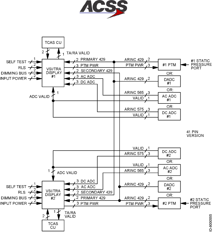
T2CAS / Part No. 9000000
SYSTEM DESCRIPTION AND INSTALLATION MANUAL
34-43-20
15 Feb 2003
Use or disclosure of information on this page is subject to the restrictions in the proprietary notice of this document.
1--48
Figure 1--14. VSI/TRA Interface Diagram (41--Pin)

T2CAS / Part No. 9000000
SYSTEM DESCRIPTION AND INSTALLATION MANUAL
34-43-20 15 Feb 2003
Use or disclosure of information on this page is subject to the restrictions in the proprietary notice of this document.
1--49
H. TAWS Terrain Hazard Display
T2CAS installations require at least one TAWS terrain hazard display. ARINC 708A and
ARINC 429 WXR display and EFIS interfaces are supported. Figure 1--15 shows a
typical single ARINC 708A terrain hazard display interface. T2CAS’ dual--independent
terrain hazard display I/O supports dual ARINC 708A and dual ARINC 429 terrain hazard
display systems.
(1) Functional Description and Operation
The terrain hazard display function enhances situational awareness by providing a
display of terrain--related hazardous situations in front of the aircraft on existing
ARINC 708A compatible weather radar or EFIS flight deck displays. The display may
be either the EFIS Navigation Display (for EFIS--equipped aircraft) or the weather
radar display. A crew--activated switch is used to select/deselect the terrain image on
the display.
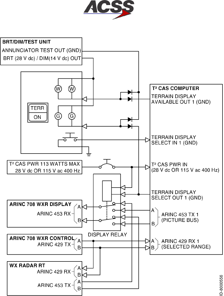
T2CAS / Part No. 9000000
SYSTEM DESCRIPTION AND INSTALLATION MANUAL
34-43-20
15 Feb 2003
Use or disclosure of information on this page is subject to the restrictions in the proprietary notice of this document.
1--50
Figure 1--15. Typical T2CAS Single Terrain Hazard Display Interface
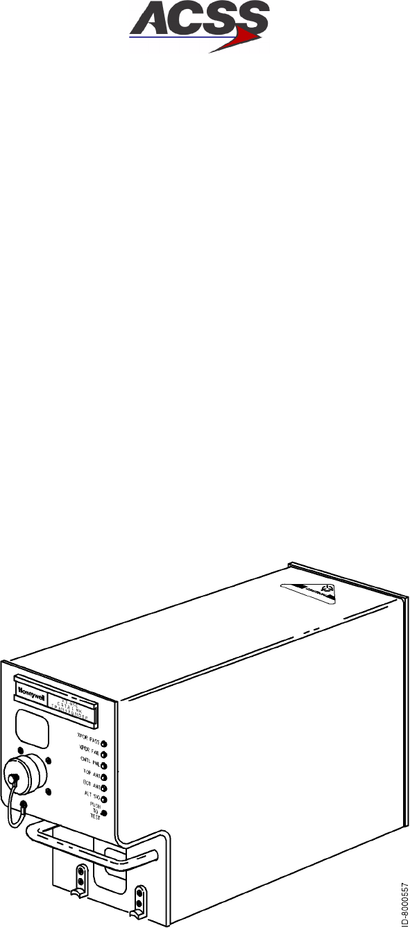
T2CAS / Part No. 9000000
SYSTEM DESCRIPTION AND INSTALLATION MANUAL
34-43-20 15 Feb 2003
Use or disclosure of information on this page is subject to the restrictions in the proprietary notice of this document.
1--51
I. XS--950 Mode S Data Link Transponder
The XS--950 Data Link Transponder provides surveillance functions to ground based and
airborne interrogators, and communication functions to various onboard systems. The
transponder contains data link functions that allow it to function as part of the Aircraft
Telecommunications Network (ATN). The data link functions allow communication with a
Communication Management Unit (CMU) through a Mode S Airborne Data Link
Processor (ADLP). The transponder also contains Mode S specific functions that are
dedicated links to onboard systems. The XS--950 Transponder has the capability to be
upgraded to provide an internal airborne data link processor (ADLP) function.
The XS--950 Transponder conforms to the ARINC 718A Mode S Transponder
Characteristic for form, fit and function, and is backward compatible with existing ARINC
718 installations. It is certified to ICAO level IV data link capability and can be upgraded
to level V data link capability.
The XS--950 Data Link Transponder is packaged in a 4--MCU (Modular Concept Unit)
outline as defined in ARINC Characteristic 600--7. The unit is able to utilize ARINC 404
cooling air moving through the LRU in a downward direction as well as ARINC 600
cooling air moving through the LRU in an upward direction. The rear connector
receptacle is an ARINC 600 size 2 shell assembly with inserts and contacts as defined in
ARINC Characteristic 718A. The unit also features a fixed carrying handle and self--test
button with discrete LRU STATUS annunciators.
Figure 1--16 shows a graphical view of the XS--950 Data Link Transponder and
Table 1--10 gives items and specifications particular to the transponder.
Figure 1--16. XS--950 Data Link Transponder

T2CAS / Part No. 9000000
SYSTEM DESCRIPTION AND INSTALLATION MANUAL
34-43-20
15 Feb 2003
Use or disclosure of information on this page is subject to the restrictions in the proprietary notice of this document.
1--52
Table 1--10. XS--950 Data Link Transponder Leading Particulars
Item Specification
Dimensions (maximum):
•Height ...................................... 7.6 in. (192 mm)
•Width ...................................... 4.9 in. (124.5 mm)
•Length ..................................... 15.2 in. (386 mm)
Weight ....................................... 11.5 lb (5.2 kg)
Power Requirements (115 V ac version):
•OperatingVoltage ............................ 97 to 134 V rms, 115 V rms nominal
•Operating Frequency ......................... 320 to 480 Hz, 400 Hz nominal
•Power Consumption:
-- Standby Mode (No Replies) ................. 40 Watts maximum
-- Active mode (Maximum Load) ............... 85 Watts maximum
•ExternalCircuitBreakerRating................. 5 A at 115 V ac, 400 Hz
Power Requirements (28 V dc version):
•OperatingVoltage ............................ +18.0 to +32.2 V dc, +27.5 V dc nominal
•Power Consumption:
-- Standby Mode (No Replies) ................. 40 Watts maximum
-- Active mode (Maximum Load) ............... 85 Watts maximum
•ExternalCircuitBreakerRating................. 7 A at 28 V dc
Mating Connector .............................. Radiall Part No. NSXN2P203X0005
Mounting ...................................... ARINC 600 4MCU Tray Assembly
TSO .......................................... C112, CL043, 121, F11
EnvironmentalSpecifications: .................... DO--160C Environmental Category
-- 115Vacversion ........................... [A2E1]--BB[CLMY]XXXXXXZEAEZRZA3E3XX
-- 28Vdcversion ........................... [A2E1]--BB[CLMY]XXXXXXZ[BZ]AZZRZA3E3XX
•Temperature / Altitude [A2E1]:
-- OperatingTemperature ..................... --55 to +70 degrees C
-- Ground Survival Temperature ............... --55 to +85 degrees C
-- Altitude ................................... Sea Level to 70,000 feet
-- LossofCooling ............................ +40 degrees C for 30 minutes minimum

T2CAS / Part No. 9000000
SYSTEM DESCRIPTION AND INSTALLATION MANUAL
34-43-20 15 Feb 2003
Use or disclosure of information on this page is subject to the restrictions in the proprietary notice of this document.
1--53
Table 1--10. XS--950 Data Link Transponder Leading Particulars(cont)
Item Specification
•Vibration [CLMY]:
-- Category C ............................... Fixed wing turbojet engine, fuselage mounting
-- Category L ............................... Fixed wing reciprocating and turboprop multi and
single engine over 12,500 pounds, fuselage
mounting
-- Category M ............................... Fixed wing reciprocating and turboprop multi and
single engine less than 12,500 pounds, instrument
panel/console and equipment rack mounting
-- Category Y ............................... Helicopter, reciprocating and turbojet, fuselage
mounting
Operating Modes:
•STANDBY................................... Ready but not replying
•ATCON .................................... Transponder Modes A and S, no altitude reporting
•ATCALT ................................... Transponder Modes A, C, and S. Altitude reporting
is enabled
Transmitter Frequency ......................... 1090 ±1.0 MHz
TransmitterPower ............................. 640 Watts maximum peak pulse, 250 Watts
minimum
Receiver Frequency ............................ 1030 MHz
Minimum Trigger Level (MTL) .................... -- 7 6 ±3dBm
Mutual Suppression ............................ Bidirectional, accepts +18 to +70 volt pulse input;
provides +28 volt nominal output
Controller Interface:
•CircuitConfiguration .......................... Two ARINC 429 control data input ports. 12.5 K
bits/s (low--speed ARINC)
•BusProtocol................................. Bus protocol meets requirements defined in ARINC
718 for receiving transponder and TCAS control
information.
TCAS II Interface:
•CircuitConfiguration .......................... ARINC 429 input and output bus. 100 K bits/s
(high--speed ARINC)
•BusProtocol................................. Bus protocol meets requirements defined in ARINC
718 and ARINC 735 for standard transponder to
TCAS interface

T2CAS / Part No. 9000000
SYSTEM DESCRIPTION AND INSTALLATION MANUAL
34-43-20
15 Feb 2003
Use or disclosure of information on this page is subject to the restrictions in the proprietary notice of this document.
1--54
Table 1--10. XS--950 Data Link Transponder Leading Particulars(cont)
Item Specification
Airborne Data Link Processor (ADLP) Interface:
•CircuitConfiguration .......................... COMM--A/B messages have an ARINC 429 input
and output bus.
COMM--C/D messages have an ARINC 429 input
and output bus.
Both sets of busses are 100 K bits/s (high--speed
ARINC).
•BusProtocol................................. Bus protocol meets requirements defined in ARINC
718 for standard transponder to ADLP bus interface.
Altimeter Interface:
•DigitalAirData............................... ARINC 429 or 575 data format. 12.5 K bits/s
(low--speed ARINC). Two altimeter inputs (left and
right altimeters).
•SynchroAltitude ............................. ARINC 407 data format. Fine and course 3--wire
synchro inputs and a synchro valid flag discrete
input. Two sets of synchro altimeter inputs (left and
right altimeters).
•Analog Altitude (--20012, --65012 Only) .......... Three wire proportional input with valid flag discrete
input. Two altimeter inputs (left and right altimeters).
Discrete input to enable altitude comparison.
•EncodingAltimeter ........................... Gillham altitude data format. 11--wire discrete input.
Two altimeter inputs (left and right altimeters).
Discrete input to enable altitude comparison.
•AltitudeSelection............................. Altitude source (left and right) selected by discrete
input.
Flight Identifier Interface:
•CircuitConfiguration .......................... ARINC 429 input bus. 12.5 K bits/s (low--speed
ARINC).
•BusProtocol................................. Flight identification field consists of eight ISO--5
characters input to the transponder in four ARINC
429 labels (233, 234, 235, 236) per the requirements
defined in ARINC 718.
Aircraft Air/Ground Status Interface ............... Two discrete inputs used to indicate the aircraft
air/ground status.
Maintenance Computer Interface:
•CircuitConfiguration .......................... ARINC 429 input and output bus. 12.5 K bits/s
(low--speed ARINC).
•BusProtocol................................. The maintenance computer interface meets protocol
requirements for all model Airbus, Boeing, and
McDonnell Douglas maintenance computers.
T2CAS / Part No. 9000000
SYSTEM DESCRIPTION AND INSTALLATION MANUAL
34-43-20 15 Feb 2003
Use or disclosure of information on this page is subject to the restrictions in the proprietary notice of this document.
1--55
Table 1--10. XS--950 Data Link Transponder Leading Particulars(cont)
Item Specification
Onboard Software Uploading / Maintenance Log
Downloading:
•CircuitConfiguration .......................... Portable Data Loader thru ARINC 615 Front Panel
Connector
ARINC 429 input and output bus (100 K bits/s) PDL
Link A discrete input
RS--232 input/output bus (38.4 K bits/s) at 53--pin
PDL connector
Airborne Data Loader thru Unit Rear Connector
ARINC 429 input and output bus (100 K bits/s) ADL
Link A discrete input
•BusProtocol................................. Software uploads thru ARINC 429 PDL (front panel)
port or ARINC 429 ADL (rear connector) port per the
protocol in ARINC 615 high--speed data loader
Maintenance log downloads thru ARINC 429 PDL
port or ARINC 429 ADL port per the protocol in
ARINC 615 high--speed data loader
Software uploads and maintenance log downloads
can be accomplished through the PDL front panel
port with an RS--232 interface bus and a PC with
terminal emulation software
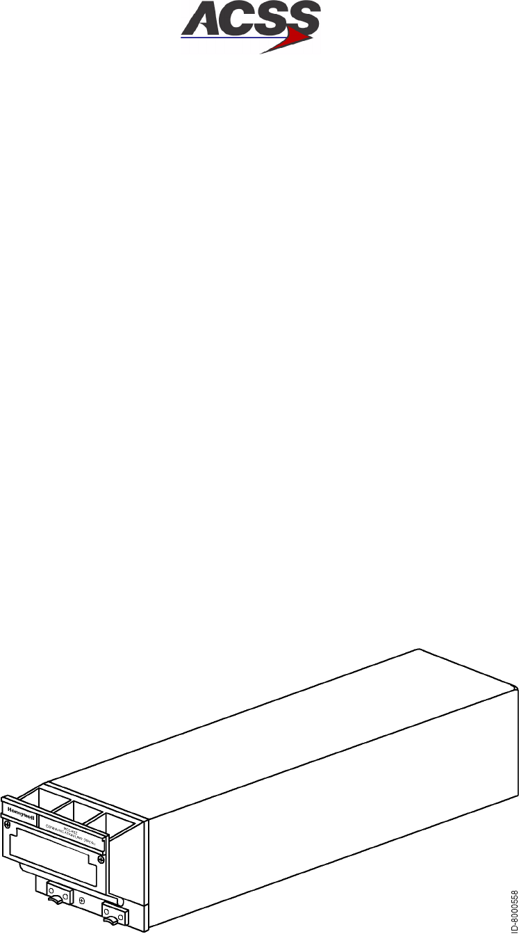
T2CAS / Part No. 9000000
SYSTEM DESCRIPTION AND INSTALLATION MANUAL
34-43-20
15 Feb 2003
Use or disclosure of information on this page is subject to the restrictions in the proprietary notice of this document.
1--56
J. RCZ--852 Diversity Mode S Transponder
The RCZ--852 Diversity Mode S Transponder is an airborne transponder designed to
perform both conventional and advanced air traffic control (ATC) functions. It receives
coded radar signals from ATC ground stations and other aircraft and transmits coded
replies. The replies contain information such as aircraft identity, altitude, and data
communication messages.
The transponder works with the air traffic control radar beacon system (ATCRBS) and
mode select (Mode S) system to provide enhanced surveillance and communications
capability required for air traffic control system automation and onboard collision
avoidance systems. It has antenna diversity and is defined as a Class 3A transponder
with TCAS interface capability. The RCZ--852 Diversity Mode S Transponder has the
capabilities that follow:
•Surveillance functions of both ATCRBS and Mode S ground sensors
•Surveillance functions of airborne interrogators
•Bi--directional air--to--air information exchanges, COMM--U/V
•Ground--to--Air data uplink, COMM--A
•Air--to--Ground data downlink, COMM--B
•Multisite message protocol
•Ground--to--Air extended length message (ELM), COMM--C.
The transponder does not support COMM--D extended length message (ELM)
communication.
Figure 1--17 shows a graphical view of the RCZ--852 Diversity Mode S Transponder and
Table 1--11 gives items and specifications particular to the transponder.
Figure 1--17. RCZ--852 Diversity Mode S Transponder

T2CAS / Part No. 9000000
SYSTEM DESCRIPTION AND INSTALLATION MANUAL
34-43-20 15 Feb 2003
Use or disclosure of information on this page is subject to the restrictions in the proprietary notice of this document.
1--57
Table 1--11. RCZ--852 Diversity Mode S Transponder Leading Particulars
Item Specification
Dimensions (maximum):
•Height ...................................... 3.38 in. (86 mm)
•Width ...................................... 4.10 in. (104 mm)
•Length ..................................... 14.1 in. (358 mm)
Weight ....................................... 5.0 lb (2.27 kg)
Power Requirements:
•OperatingVoltage ............................ +18.0 to +30.3 V dc, +27.5 V dc nominal
•Power Consumption:
-- Standby Mode (No Replies) ................. 28 Watts nominal
-- Active Mode (Maximum Load) ............... 55 Watts maximum
•ExternalCircuitBreakerRating................. 5 A at +27.5 V dc
Mating Connector .............................. Radiall Part No. NSXN2P203X0005 (Part of
Installation Kit, ACSS Part No. 7510707--968)
Mounting ...................................... Mount Assembly, ACSS Part No. 7517455--902
TSO .......................................... C112
EnvironmentalSpecifications..................... DO--160B Environmental Category
/A2E1/B/JLMY/E1XXXXXZ/BZ/AZZ
•Temperature / Altitude [A2E1]:
-- OperatingTemperature ..................... --55 to +70 degrees C
-- Ground Survival Temperature ............... --55 to +85 degrees C
-- Altitude................................... Sea Level to 70,000 feet
-- Decompression ............................ 8,000 to 70,000 feet
-- Overpressure ............................. --15,000 feet
•Vibration [JLMY]:
-- Category J ............................... Fixed wing turbojet, subsonic and supersonic,
fuselage mounting
-- Category L ............................... Fixed wing reciprocating and turboprop multi and
single engine over 12,500 pounds, fuselage
mounting
-- Category M ............................... Fixed wing reciprocating and turboprop multi and
single engine less than 12,500 pounds, instrument
panel/console and equipment rack mounting
-- Category Y ............................... Helicopter, reciprocating and turbojet, fuselage
mounting

T2CAS / Part No. 9000000
SYSTEM DESCRIPTION AND INSTALLATION MANUAL
34-43-20
15 Feb 2003
Use or disclosure of information on this page is subject to the restrictions in the proprietary notice of this document.
1--58
Table 1--11. RCZ--852 Diversity Mode S Transponder Leading Particulars (cont)
Item Specification
Operating Modes:
•STANDBY................................... Ready but not replying.
•ATCON .................................... Transponder Modes A and S. No altitude reporting.
•ATCALT ................................... Transponder Modes A, C, and S. Altitude reporting
is enabled.
Transmitter Frequency ......................... 1090 ±0.5 MHz
TransmitterPower ............................. 500 Watts peak pulse, 250 Watts minimum
Receiver Frequency ............................ 1030 MHz
Minimum Trigger Level (MTL) .................... -- 7 7 ±3dBm
Mutual Suppression ............................ Bidirectional, accepts +18 to +70 volt pulse input,
provides +28 volt nominal output
Controller interface:
•CircuitConfiguration .......................... Two ARINC 429 control data input ports. 12.5 K
bits/s (low--speed ARINC)
Radio System Bus (RSB)
•BusProtocol................................. Bus protocol meets requirements defined in ARINC
718 for receiving transponder and TCAS control
information.
The Radio System Bus (RSB) is designed to work
with the Honeywell Radio Management Unit.
TCAS II Interface:
•CircuitConfiguration .......................... ARINC 429 input and output bus. 100 K bits/s
(high--speed ARINC).
•BusProtocol................................. Bus protocol meets requirements defined in ARINC
718 and ARINC 735 for standard transponder to
TCAS interface.
Airborne Data Link Processor (ADLP) Interface:
•CircuitConfiguration .......................... COMM--A/B messages have an ARINC 429 input
and output bus.
COMM--C/D messages have an ARINC 429 input
and output bus.
Both sets of busses are 100 K bits/s (high--speed
ARINC).
•BusProtocol................................. Bus protocol meets requirements defined in ARINC
718 for standard transponder to ADLP bus interface.
•Exception ................................... COMM--D messages are not processed by this
transponder.

T2CAS / Part No. 9000000
SYSTEM DESCRIPTION AND INSTALLATION MANUAL
34-43-20 15 Feb 2003
Use or disclosure of information on this page is subject to the restrictions in the proprietary notice of this document.
1--59
Table 1--11. RCZ--852 Diversity Mode S Transponder Leading Particulars (cont)
Item Specification
Altimeter Interface:
•DigitalAirData............................... ARINC 429 or 575 data format. 12.5 K bits/s
(low--speed ARINC). Two altimeter inputs (left and
right altimeters).
•IACAirData ................................. Radio System Bus (RSB) interface supplies the
Honeywell Integrated Avionics Computer (IAC)
digital air data information. Two altimeter inputs (left
and right altimeters).
•EncodingAltimeter ........................... Gillham altitude data format. 11--wire discrete input.
Two altimeter inputs (left and right altimeters).
Discrete input to enable altitude comparison.
•AltitudeSelection............................. Altitude source (left or right) selected by a discrete
input.
Flight Identifier Interface:
•From Radio Management (RMU) ............... Flight identifier input from the RMU in RSB data
format.
•From Flight Management System (FMS) ........ Flight identifier input from the FMS in ARINC 429
data format. 12.5 K bits/s (low--speed ARINC).
Aircraft Air/Ground Status Interface ............... Two discrete inputs used to indicate the aircraft
air/ground status.
Antenna Selection Interface ...................... A discrete output supplies a GROUND when
transponder is active.
RCB Interface:
•CircuitConfiguration .......................... 2--wire full duplex RS--232 serial link to/from internal
radio communications bus (RCB).
•TransmissionRate ........................... 187.5 K baud
•TransmissionFormat ......................... 1startbit,8databitsand1stopbit
Shop Flash Memory Programming Interface:
•CircuitConfiguration .......................... 2--wire full duplex RS--232 serial port
•TransmissionRate ........................... 19.2 K baud
•TransmissionFormat ......................... 1 start bit, 7 data bits, odd parity and 1 stop bit

T2CAS / Part No. 9000000
SYSTEM DESCRIPTION AND INSTALLATION MANUAL
34-43-20
15 Feb 2003
Use or disclosure of information on this page is subject to the restrictions in the proprietary notice of this document.
1--60
5. System Operation
A. TCAS Operation
The principal modes of operation and display features of the TCAS function are
discussed in the paragraphs that follow. In--flight procedures with display examples are
contained in the T2CAS Pilot’s Manual, ACSS Publication No. 8000264--001.
(1) Operational Modes
The TCAS function can operate in several different modes, depending on control
panel selection. Several control panels are available. Only the ACSS single Mode S
control panel is discussed. Other control panels provide similar features.
Four switches directly affect the TCAS operational mode: TCAS/XPDR mode
selector, TA DSPLY selector, ALT RPTG selector, and TCAS TEST switch. To
distinguish the modes that provide TCAS advisories from those that do not, the
operational modes are discussed under TCAS modes and non--TCAS modes. The
non--TCAS modes are annunciated TCAS OFF at the center of the display.
The extended test mode is mentioned for reference. A detailed description of its use
can be found in the FAULT ISOLATION section.
(a) TCAS Modes
The TA/RA and the TA--only modes are the two TCAS operational modes. The
TA/RA mode gives traffic information and warnings of hazardous traffic conflicts,
while the TA mode gives only traffic information. A third mode, the TEST mode,
can be temporarily activated from any mode including standby (STBY). The
TEST mode does not inhibit the generation of advisories. Functions available in
the operational and test modes are as follows:
1TA/RA Mode
This mode is the normal operation mode providing full TCAS coverage. In
this mode, TCAS tracks all aircraft in the surrounding airspace and
generates traffic advisories or resolution advisories, as the situation requires.
Figure 1--3 contrasts the airspace covered for each kind of advisory.
For normal TA/RA operation, the TA/DSPLY selector must be set to AUTO or
ON and the ALT/RPTG selector must be set to 1 or 2.
2TA Mode
The TA mode provides only surveillance of the surrounding airspace. In this
mode, TCAS tracks all proximate aircraft and generates traffic advisories; no
resolution advisories are issued in this mode.
The flight crew uses the TA--only mode when resolution advisories would be
a nuisance, or when flying over an area where only TCAS surveillance is
allowed. Also, the system automatically selects this mode when the aircraft
is flying under 1000 feet above ground level (AGL).
The TA mode is annunciated TA ONLY at the upper left corner of the display.

T2CAS / Part No. 9000000
SYSTEM DESCRIPTION AND INSTALLATION MANUAL
34-43-20 15 Feb 2003
Use or disclosure of information on this page is subject to the restrictions in the proprietary notice of this document.
1--61
3Test Mode
Pushing the TEST button on the control panel starts a self--test program
which verifies proper operation of the TA and RA displays and of the aural
advisories on the audio system.
The test mode does not affect normal TCAS operation, provided the
selected transponder remains in normal operation during the test cycle.
Should a TA or RA occur during the test sequence, the test aborts, and the
advisory is announced and displayed.
The test mode just described excludes extended self--tests performed on the
ground, where TCAS is inoperative.
(b) Non--TCAS Modes
The control panel selections that follow disable TCAS operation and all
advisories:
•MODE S ON activates a Mode S transponder only
•STBY sets the selected transponder in standby mode
•ATC activates an ATCRBS transponder only
•ALT RPTG set to OFF inhibits altitude reporting.
When TCAS is inoperative as a result of control panel selection, TCAS OFF is
annunciated on the display. When TCAS is inoperative due to a system failure,
TA FAIL, RA FAIL, or TCAS FAIL is annunciated on the display. In addition, if the
transponder or the altitude data source fails, the XPDR FAIL light on the control
panel comes on.
(c) Extended Test Mode
The purpose of the extended test mode is to facilitate diagnosis in the event
self--test has failed. Like self--test, this mode is enabled by pushing the TCAS
TEST button, but only when TCAS is inoperative. The aircraft must be on the
ground, and the transponder must be set to STBY. Push and hold the TCAS
TEST button for longer than eight seconds to activate the extended tests. This
feature is not available on all systems. Refer to the TESTING AND FAULT
ISOLATION section for system requirements and test description.
T2CAS / Part No. 9000000
SYSTEM DESCRIPTION AND INSTALLATION MANUAL
34-43-20
15 Feb 2003
Use or disclosure of information on this page is subject to the restrictions in the proprietary notice of this document.
1--62
(2) Display Symbology
The TCAS modes use color--coded symbols and data tags to map air traffic and
locate threat aircraft on the VSI/TRA display.
Four traffic symbols are used: solid circle, solid square, solid diamond, and hollow
diamond. See Figure 1--18 for examples. A different color is assigned to each
symbol type, as listed in Table 1--12.
Table 1--12. TCAS Traffic Symbols
Graphic Symbol Color Display Function
Solid Circle Amber Traffic Advisory (TA)
Solid Square Red Resolution Advisory (RA)
Solid Diamond Blue Proximate Traffic
Hollow Diamond Blue Other Traffic
NOTE: TCAS traffic information displayed on EFIS displays such as crew alerting
system display, navigation display, electronic horizontal situation display or
multifunction display, is similar to that on combined VSI/TRA indicators. Traffic
symbology is identical to that displayed on the VSI/TRA.
(a) Colors
1Amber
Represents a moderate threat to a TCAS--equipped aircraft. A visual search
is recommended to prepare for intruder avoidance. Amber is used only in
conjunction with a traffic advisory.
2Red
Represents an immediate threat to a TCAS--equipped aircraft. Prompt
action is required to avoid the intruder. This color is only used in conjunction
with a resolution advisory.
3Blue
Represents proximate traffic and other traffic the TCAS surveillance logic
has in its track file.
4White
Used only for mode annunciations and for reference graphics, including
aircraft home position, range ring, and VSI scale.
(b) Traffic Identification
1Traffic Advisory

T2CAS / Part No. 9000000
SYSTEM DESCRIPTION AND INSTALLATION MANUAL
34-43-20 15 Feb 2003
Use or disclosure of information on this page is subject to the restrictions in the proprietary notice of this document.
1--63
Intruder aircraft entering the caution area, 20 to 48 seconds from the TCAS
2000 collision area are represented as a solid amber circle. This type of
traffic results in a traffic advisory.
2Resolution Advisory
Intruder aircraft entering the warning area, 15 to 35 seconds from the TCAS
2000 collision area are represented as a solid red square. This type of
traffic results in a resolution advisory.
3Proximate Traffic
Aircraft within 6.0 nautical miles and 1200 feet vertically are represented
as a solid cyan diamond. Proximate traffic is shown to improve situational
awareness in the event of a potential conflict with higher priority RA or TA
aircraft.
4Other Traffic
Any transponder replying to traffic not classified as an intruder or proximate
traffic, and within 2700 feet vertically and the range of the display are
represented as hollow cyan diamonds (only in view with the traffic switch ON
and no TA or RA in process). The predicted flightpaths of proximate and
other traffic do not penetrate the collision area of the TCAS aircraft.
(c) Data Tags
A data tag, made up of a two--digit number, a plus (+) or a minus (--) sign, and
may also include an arrow, appears either above or below the intruder aircraft
symbol. The data tag appears in the same color as the advisory.
1Two--digit Number (Relative Altitude)
Represents the relative altitude difference, in hundreds of feet, either above
or below the TCAS aircraft of an intruder aircraft. For an intruder above the
TCAS aircraft, the data tag is placed above the traffic symbol and preceded
by a plus (+) sign; for one below, the tag is placed below the traffic symbol
and be preceded by a minus (--) sign.
2Plus (+) or Minus (--) Sign
Appears adjacent to the relative altitude number and indicates whether the
displayed aircraft is above (plus) or below (minus) the TCAS aircraft.
3Arrow
A vertical arrow is placed to the immediate right of the traffic symbol if the
intruder is either climbing (up arrow) or descending (down arrow) in excess
of 500 feet per minute.

T2CAS / Part No. 9000000
SYSTEM DESCRIPTION AND INSTALLATION MANUAL
34-43-20
15 Feb 2003
Use or disclosure of information on this page is subject to the restrictions in the proprietary notice of this document.
1--64
(d) VSI Scale Overlays
During a resolution advisory, red and green bands overlay the VSI scale. The
red band indicates what vertical speed range is to be avoided by the pilot
(prohibited vertical speed). The green band indicates the vertical speed the pilot
is to attain to achieve safe separation from a threat aircraft (recommended
vertical speed). The red/green band reflects the RA in progress and acts as a
vertical speed advisory for the pilot.
(e) Reference Graphics and Annunciations
A white airplane symbol is displayed in the lower center of the VSI representing
the aircraft own position. A white range ring made up of 12 dots, each
corresponding to a normal clock position, is included. The range ring surrounds
the airplane with a radius of 2 nautical miles and is intended to assist in
interpreting TCAS traffic information.
The scale of the VSI display is 6.0 nautical miles to the top display edge of the
VSI (ahead of the aircraft), 4 miles to the left and right edges, and 2.5 nautical
miles to the bottom (behind the aircraft).
Annunciations in white letters serve as a reminder of the current operation mode.
They include TCAS OFF, TA only and RA only. Fault annunciations in amber
letters replace the mode annunciations in case of system failure. They include
TCAS FAIL, RA FAIL, VSI FAIL, and TA FAIL (traffic display failure). Figure 1--14
shows a typical failure display.
(3) Aural Messages
The TCAS generates aural alerts or messages announced over the aircraft audio
system. These messages accompany the visual TA or RA display and are softened
or strengthened, depending on the urgency of the situation. The TCAS audio level is
preset and is not adjustable by the aircrew.
If a logic change occurs before a message is completed and a new message is
initiated, the original alert is terminated and the new alert announced immediately.
(a) Requirements and Limitations
The following is a list of the requirements and limitations for issuing an aural
advisory by the T2CAS Computer Unit:
1Voice announcements are inhibited below 500 feet above ground level
(AGL).
2The CANCEL BUTTON, which is reserved for future use on the --XX001
T2CAS CUs only, halts voice announcements after the CANCEL BUTTON is
activated. An aural advisory in progress is terminated and not repeated after
deactivation of the CANCEL BUTTON.

T2CAS / Part No. 9000000
SYSTEM DESCRIPTION AND INSTALLATION MANUAL
34-43-20 15 Feb 2003
Use or disclosure of information on this page is subject to the restrictions in the proprietary notice of this document.
1--65
3During T2CAS computer unit self--test, an aural advisory confirms proper
operation of the aural advisory system by annunciating the message “TCAS
TEST”. The aural advisory system annunciates the pass/fail status of any
monitored functions with the messages “TCAS TEST PASS” and “TCAS
TEST FAIL”, respectively.
4An aural advisory tone will precede each aural advisory when the audio tone
enable program pin has been activated.
5T2CAS computer unit TCAS aural alerts are inhibited when the advisory
inhibit discrete input No. 4 is grounded. An aural advisory in progress is
disabled after the grounding of advisory inhibit discrete No. 4. The truncated
message is annunciated in its entirety once the inhibit discrete has been
released. This capability is used to defer all advisory (TA and RA), aural
alert, and visual alert outputs until another, higher priority
announcement/alert is completed.
6Increases and decreases in the threat level are aurally annunciated.
However, decreases in threat level are annunciated once and are not
preceded by setting the audio tone discrete. For example, a vertical speed
restriction following a climb RA is annunciated once.
(b) Traffic Advisory (TA) Message
The traffic advisory aural alert, TRAFFIC -- TRAFFIC is spoken once, and then
inhibited until the next TA occurs. This alert occurs when TCAS predicts an
intruder will enter the collision area within 20 to 48 seconds. Simultaneously, the
TCAS traffic display shows the location of the intruder.
(c) Resolution Advisory (RA) Messages
Resolution advisories indicate evasive vertical maneuvers calculated to increase
separation between the TCAS aircraft and the intruder (corrective advisory), or to
indicate certain changes in vertical speed are not recommended (preventive).
Resolution advisory messages made up of a single word are repeated three
times; longer messages are repeated twice.
RAs are annunciated on the T2CAS computer unit using the voice messages
listed below as determined by Collision Avoidance System (CAS) data. The
following messages will not immediately follow another message from this
paragraph if it causes a reversal of sense. For example, a “CLIMB, CLIMB”
message cannot immediately follow a :”DESCEND, DESCEND” message.
1“CLIMB, CLIMB”: Climb at the rate shown on the VSI or other suitable
indicator.
2“DESCEND, DESCEND”: Descend at the rate shown on the VSI or other
suitable indicator.

T2CAS / Part No. 9000000
SYSTEM DESCRIPTION AND INSTALLATION MANUAL
34-43-20
15 Feb 2003
Use or disclosure of information on this page is subject to the restrictions in the proprietary notice of this document.
1--66
3“MONITOR VERTICAL SPEED”: Verify that vertical speed is out of the
illuminated red VSI arc, or comply with another suitable indicator. Additional
T2CAS CU messages are “MAINTAIN VERTICAL SPEED, MAINTAIN:
MAINTAIN VERTICAL SPEED, CROSSING MAINTAIN”: or “ADJUST
VERTICAL SPEED, ADJUST”. Safe separation is based upon maintaining
the current vertical speed.
4“ADJUST VERTICAL SPEED, ADJUST”: Reduce climb or descent rate.
5“MAINTAIN VERTICAL SPEED, MAINTAIN”: Safe separation is based upon
maintaining the current vertical speed.
6“MAINTAIN VERTICAL SPEED, CROSSING, MAINTAIN”: Maintain vertical
speed while crossing the intruder’s flight path. This advisory is implemented
on --XX003 TCAS CUs.
7“CLEAR OF CONFLICT”: Range is increasing, and separation is adequate;
return to assigned clearance.
8“CLIMB, CROSSING CLIMB—CLIMB, CROSSING CLIMB”: Safe separation
is best be achieved by climbing through intruder’s flight path.
9“DESCEND, CROSSING DESCEND, DESCEND, CROSSING DESCEND”:
Safe separation is best achieved by descending through the intruder’s flight
path.
(d) Enhanced RA Messages
Enhanced RAs are annunciated on the T2CAS computer unit using the voice
messages listed below as designated by the CAS data when the initial resolution
advisory does not provide sufficient vertical separation. These messages are
annunciated to convey a sense of urgency. The following messages can
immediately follow a message from the previous paragraph and have a reversal
of sense.
NOTE: These advisories are expected to occur only on rare occasions, usually
when an intruder suddenly changes its current flightpath. (Maneuvering
intruder)
1“INCREASE CLIMB, INCREASE CLIMB”: (Received after a “CLIMB”
advisory) Indicates additional climb rate required to achieve safe vertical
separation from a maneuvering intruder.
2“INCREASE DESCENT, INCREASE DESCENT”: (Repeated two times,
received after “DESCEND” advisory) Indicates additional descent rate
required to achieve safe vertical separation from a maneuvering intruder.
3“CLIMB, CLIMB NOW!—CLIMB,CLIMB NOW!”: (Received after a
“DESCEND” resolution advisory) Indicates a reversal in sense is required to
achieve safe vertical separation from a maneuvering intruder.

T2CAS / Part No. 9000000
SYSTEM DESCRIPTION AND INSTALLATION MANUAL
34-43-20 15 Feb 2003
Use or disclosure of information on this page is subject to the restrictions in the proprietary notice of this document.
1--67
4“DESCEND, DESCEND NOW!—DESCEND, DESCEND NOW!”: (Received
after a “CLIMB” resolution advisory) Indicates a reversal in sense is required
to achieve safe vertical separation from a maneuvering intruder.
(4) Operating Procedures
Basic TCAS operating procedures on the ground include pre--flight test, TCAS
activation before takeoff, and TCAS deactivation after landing. In--flight procedures
are contained in the pilot’s manual.
(a) Pre--Flight Test
The VSI/TRA self--test feature provides a convenient method to test the TCAS
system before takeoff.
NOTE: Self--test can be initiated at any time, on the ground or in flight (if not
disabled in air by grounding pin RBP--8E), by momentarily pushing
TCAS TEST. If TAs and RAs occur while self--test is activated in flight,
the test aborts, and the advisories are processed and displayed.
To perform self--test, push the TCAS TEST button on the control panel and
monitor the sequence that follows:
•Aural annunciation TCAS TEST is heard on audio system.
•Test pattern with fixed traffic and advisory symbols appears on the display for
eight seconds.
•Make sure the test pattern is as shown in Figure 1--18. The test pattern
includes:
-- An RA symbol at 3 o’clock, 2 nm, 200 ft above, in level flight
-- A TA symbol at 9 o’clock, 2 nm, 200 ft below, climbing
-- A proximate traffic symbol at 3.6 nm, 33 degrees right of the aircraft
heading (approximately 1 o’clock), 1000 ft below, descending
-- A non--threat intruder (other traffic symbol) at 3.6 nm, 33 degrees left of the
aircraft heading (approximately 11 o’clock), 1000 ft above, in level flight
-- Red and green resolution advisory VSI overlay indicating a don’t descend,
don’t climb > 2000 ft/min advisory
-- TCAS TEST or RA OFF annunciation, depending on the capabilities of the
display.
-- After 8 seconds, TCAS TEST PASS is announced, and the test pattern is
replaced with the normal VSI display.
-- If self--test fails, TCAS TEST FAIL is announced, and TCAS FAIL appears
on the display. To obtain failure data, perform the extended test mode
procedure in the next section.
(b) TCAS Mode Activation
Prior to takeoff, activate TCAS as follows:
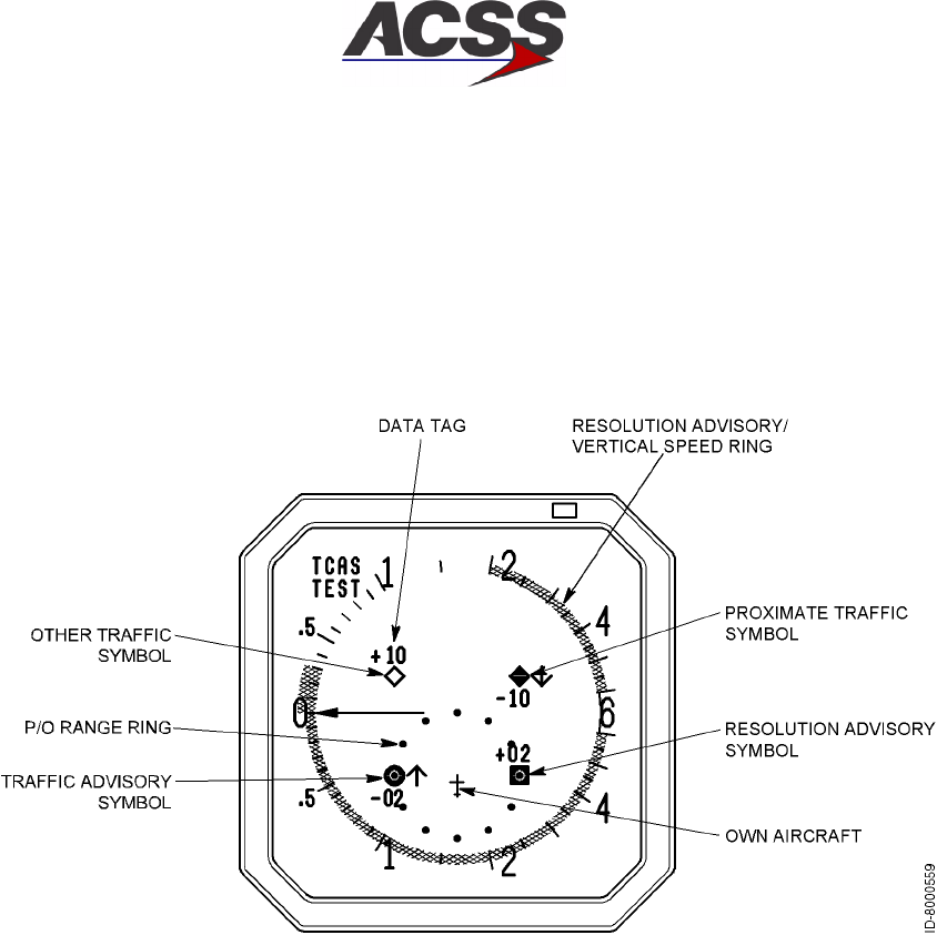
T2CAS / Part No. 9000000
SYSTEM DESCRIPTION AND INSTALLATION MANUAL
34-43-20
15 Feb 2003
Use or disclosure of information on this page is subject to the restrictions in the proprietary notice of this document.
1--68
•Set TCAS/XPDR mode selector to TA/RA
•Set TA/DSPLY to AUTO
•Set ALT/RPTG to 1 or 2.
(c) TCAS Mode Deactivation
After clearing the runway following landing, set the TCAS/XPDR mode selector
to STBY to disable Mode S communication.
Figure 1--18. TCAS ll Display Test Pattern
B. TAWS/RWS Operation
The principal modes of operation and display features of the TAWS/RWS function are
discussed in the paragraphs that follow. In--flight procedures with display examples are
contained in the T2CAS Pilot’s Manual, ACSS Publication No. 8000264--001.
(1) TAWS Operational Modes
The T2CAS TAWS function provides both conventional GPWS and Collision
Prediction & Alerting (CPA) modes of operation.
The conventional GPWS modes of operation are as follows:
(a) Mode 1: Excessive Rate of Descent with respect to Terrain
When the CPA mode is inoperative, this mode provides, as defined in RTCA
DO--161A, a reactive medium--term caution and a reactive short--term warning
when the current flight path is descending toward the terrain ahead of the aircraft
at an excessive rate. Figure 1--19 shows Mode 1 -- Excessive Descent Rate
Envelope.

T2CAS / Part No. 9000000
SYSTEM DESCRIPTION AND INSTALLATION MANUAL
34-43-20 15 Feb 2003
Use or disclosure of information on this page is subject to the restrictions in the proprietary notice of this document.
1--69
Figure 1--19. Mode 1 -- Excessive Descent Rate Envelope
(b) Mode 2: Excessive Closure Rate to Terrain
When the CPA mode is inoperative, this mode provides, as defined in RTCA
DO--161A, a reactive medium--term caution and a reactive short--term warning
when the current flight path and the terrain ahead of the aircraft are closing at an
excessive rate. Figure 1--20 shows Mode 2 -- Excessive Terrain Closure Rate
Envelope.
Figure 1--20. Mode 2 -- Excessive Terrain Closure Rate Envelope
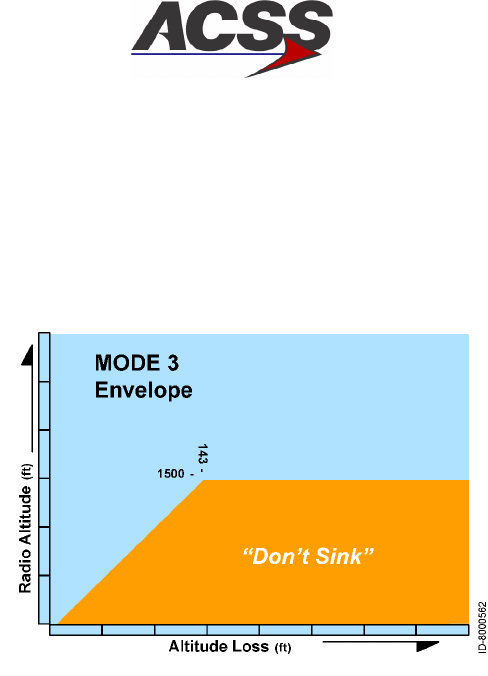
T2CAS / Part No. 9000000
SYSTEM DESCRIPTION AND INSTALLATION MANUAL
34-43-20
15 Feb 2003
Use or disclosure of information on this page is subject to the restrictions in the proprietary notice of this document.
1--70
(c) Mode 3: Excessive Altitude Loss after Take--off
This mode provides, as derived from RTCA DO--161A, an alert when there is a
loss of altitude after take--off or during a missed approach. Figure 1--21 shows
Mode 3 -- Loss of Altitude After Take Off Envelope.
Figure 1--21. Mode 3 -- Excessive Altitude Loss After Take Off Envelope
(d) Mode 4: Incorrect Aircraft Configuration with regard to Terrain
T2CAS meets the requirement for Mode 4 alerts as defined in RTCA DO--161A.
Mode 4 applies during the landing phase of flight and results in the annunciation
of an alert in the event of insufficient terrain clearance when the aircraft is not in
the proper landing configuration. Mode 4 consists of the following two
sub--modes:
•Mode 4A, when the landing gear is up
•Mode 4B, when the landing gear is down, but the flaps are not in landing
configuration
Figure 1--22 shows Mode 4 -- Unsafe Terrain Clearance Envelope.
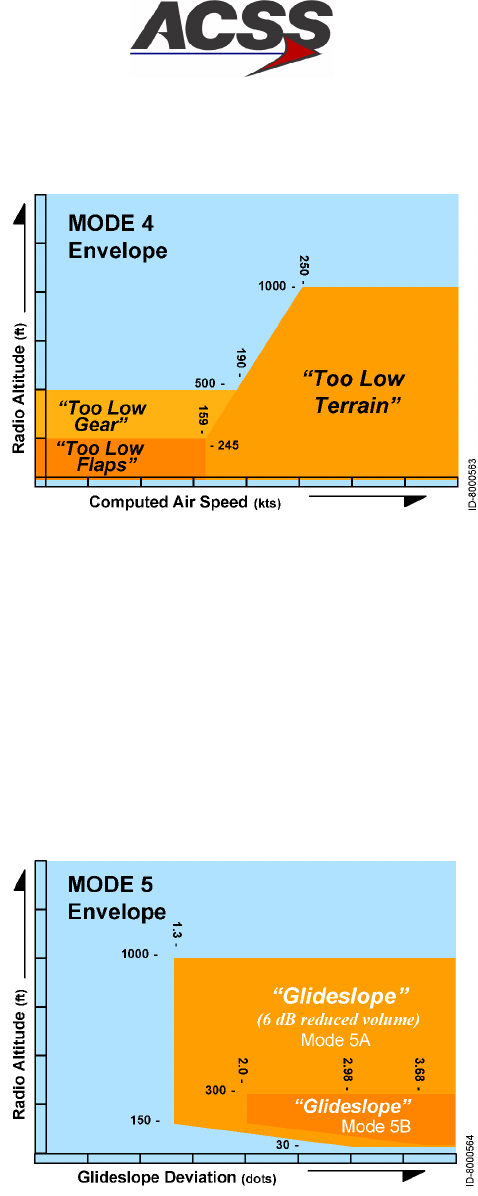
T2CAS / Part No. 9000000
SYSTEM DESCRIPTION AND INSTALLATION MANUAL
34-43-20 15 Feb 2003
Use or disclosure of information on this page is subject to the restrictions in the proprietary notice of this document.
1--71
Figure 1--22. Mode 4 -- Unsafe Terrain Clearance Envelope
(e) Mode 5: Excessive Glide Path Deviation
T2CAS meets the requirement for Mode 5 alerts as defined in RTCA DO--161A.
Mode 5 applies in the event of an excessive descent below the instrument glide
path when making a front--course approach with the gear down. In a
back--course landing configuration, mode 5 is automatically inhibited.
Figure 1--23 shows Mode 5 -- Excessive Glide Path Deviation Envelope.
Figure 1--23. Mode 5 -- Excessive Glide Path Deviation Envelope
(f) Altitude Call--outs
The T2CAS TAWS function produces call--outs and alerts for descent below a set
of customer defined altitudes.
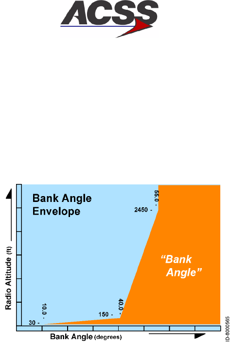
T2CAS / Part No. 9000000
SYSTEM DESCRIPTION AND INSTALLATION MANUAL
34-43-20
15 Feb 2003
Use or disclosure of information on this page is subject to the restrictions in the proprietary notice of this document.
1--72
(g) Excessive Bank Angle
The T2CAS TAWS function produces call--outs and alerts for descent below a set
of predefined altitudes and for excessive bank angle. Figure 1--24 shows
Excessive Bank Angle Envelope.
Figure 1--24. Excessive Bank Angle Envelope
The CPA mode of operation provides medium--term (caution) and short--term
(warning) alerts to inform the crew that the flight path they are following is hazardous
due to the presence of terrain ahead. The objective of the CPA function is to warn
the crew of an impending controlled flight into terrain with sufficient time for them to
assess the situation and safely avoid the terrain hazard. All CPA predictions are
based on the assumption that the operational escape maneuver in case of a terrain
hazard will be a ”pull up” evasive action. CPA predictions model a conservative pull
up escape maneuver based on current aircraft climb capability.
The T2CAS CPA function provides alerts in the following CFIT situations:
•Hazardous descent rate with respect to terrain
•Hazardous closure rate with respect to terrain
•Hazardous terrain ahead situation during turns
•Hazardous high terrain ahead situation that can not be cleared by a pull up
maneuver
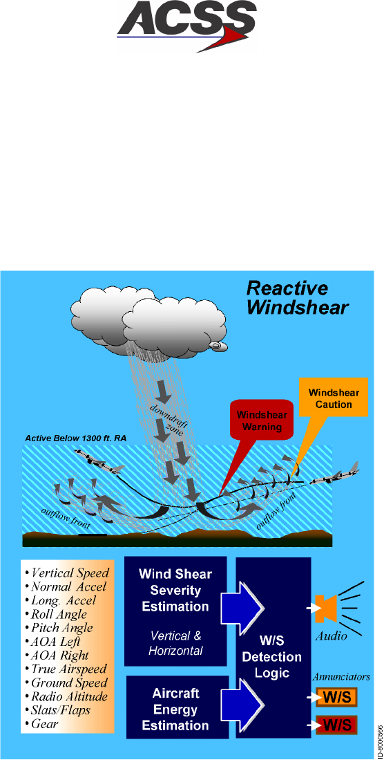
T2CAS / Part No. 9000000
SYSTEM DESCRIPTION AND INSTALLATION MANUAL
34-43-20 15 Feb 2003
Use or disclosure of information on this page is subject to the restrictions in the proprietary notice of this document.
1--73
(2) RWS Operational Mode
Whenever wind factors cause aircraft performance to decrease to a predetermined
level, an audio warning is sounded, indicating to the crew that the aircraft net
performance capability is deteriorating and rapidly approaching a critical state. In
addition to the warning, the Windshear Warning algorithm provides a caution when
an increasing--performance Windshear is detected, thus giving advance warning of
decreasing--performance windshear. Figure 1--25 illustrates reactive windshear
detection.
Figure 1--25. Windshear Detection
(3) TAWS Display Symbology
The terrain hazard display function generates an image that provides the following
information to the flight crew:
•A Terrain Display Background consisting of shaded areas representing terrain at
different altitudes relative to the aircraft altitude
•An Alert Line depicting the point or points where a CPA caution will occur if the
aircraft continues on its current trajectory
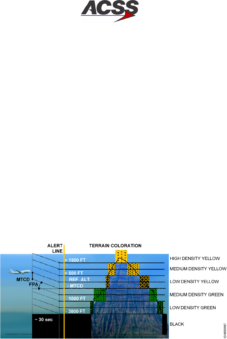
T2CAS / Part No. 9000000
SYSTEM DESCRIPTION AND INSTALLATION MANUAL
34-43-20
15 Feb 2003
Use or disclosure of information on this page is subject to the restrictions in the proprietary notice of this document.
1--74
•Terrain Alert areas corresponding to the terrain that is causing a CPA caution or
warning.
Each of these features is explained in the following sub--sections.
(a) Terrain Display Background
The purpose of the Terrain Display Background is to provide overall situational
awareness to the crew about the relative height of the terrain near the aircraft.
The terrain is divided into ”slices” based on the elevation of the terrain with
respect to an aircraft reference altitude. Slices above or very near the reference
altitude are typically shown as varying shades of yellow. Slices safely below the
reference altitude are typically shown as varying shades of green or even black.
The reference altitude is a surface starting at the aircraft and propagating
forward along the aircraft flight path angle for 30 seconds. The reference altitude
surface then extends horizontally at the altitude the aircraft is expected to have
at that time (i.e., 30 seconds in the future).
The specific colors and textures used for the various slices, as well as the
threshold altitudes for the slices, are contained in the Aircraft Specific Database
(ASDB) and thus can be tailored for specific installations. Figure 1--26 shows a
typical color scheme and altitude definitions. (Note: The figure is drawn in color.
If this document is printed in black and white, the different yellow and green
textures representing different terrain elevations will appear as different shades
of gray.)
Figure 1--26. Terrain Slices
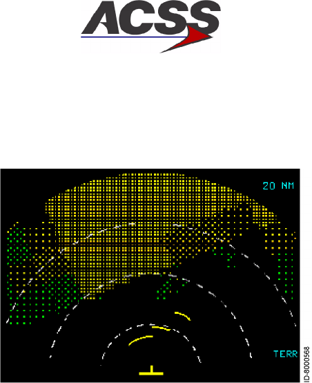
T2CAS / Part No. 9000000
SYSTEM DESCRIPTION AND INSTALLATION MANUAL
34-43-20 15 Feb 2003
Use or disclosure of information on this page is subject to the restrictions in the proprietary notice of this document.
1--75
A typical terrain background image is shown in Figure 1--27
Figure 1--27. Terrain Display Background
(b) Alert Line Display
The Terrain Hazard Display can also depict an Alert Line. The Alert Line is
drawn at the points where a CPA caution will occur if the aircraft continues along
it’s current vertical trajectory. When there are no CPA cautions or warnings
active, T2CAS TAWS will determine if an alert line needs to be drawn. Beginning
at the current aircraft position, T2CAS TAWS looks ahead of the aircraft to
determine where a CPA caution will occur. T2CAS TAWS will look up to 120
seconds into the future and look at all headings within 30 degrees of the current
aircraft heading. If any CPA cautions would be triggered in this area, the alert
line will be drawn on the terrain hazard display.
Figure 1--28 illustrates the alert line. The alert line is the solid yellow line located
at about the 5 NM range ring. As the aircraft continued, this line (as well as the
background terrain) would get closer to the aircraft symbol. When the alert line
reached the aircraft symbol, a CPA caution would occur. Thus the alert line
provides the flight crew an advance indication of when CPA alerts will occur. The
alert line is not displayed when a CPA caution or warning is active.
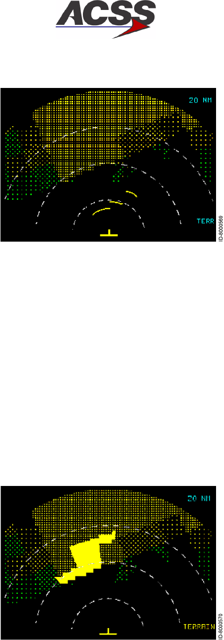
T2CAS / Part No. 9000000
SYSTEM DESCRIPTION AND INSTALLATION MANUAL
34-43-20
15 Feb 2003
Use or disclosure of information on this page is subject to the restrictions in the proprietary notice of this document.
1--76
Figure 1--28. Alert Line
(c) Display of Terrain Alerts
When a CPA caution or warning occurs, the terrain that caused the alert will be
displayed on the Terrain Hazard Display. Solid yellow is used for cautions, solid
red is used for pull--up warnings, and black x’s on a solid red background are
used for avoid terrain warnings.
In Figure 1--29, the caution alarm is generated through the TAWS display by
highlighting the hazardous area ahead of the aircraft in yellow and generating a
yellow ”TERRAIN” message on the bottom right of the screen. An aural message
is also played on the flight deck.
Figure 1--29. Terrain Hazard Display Upon Caution Alert
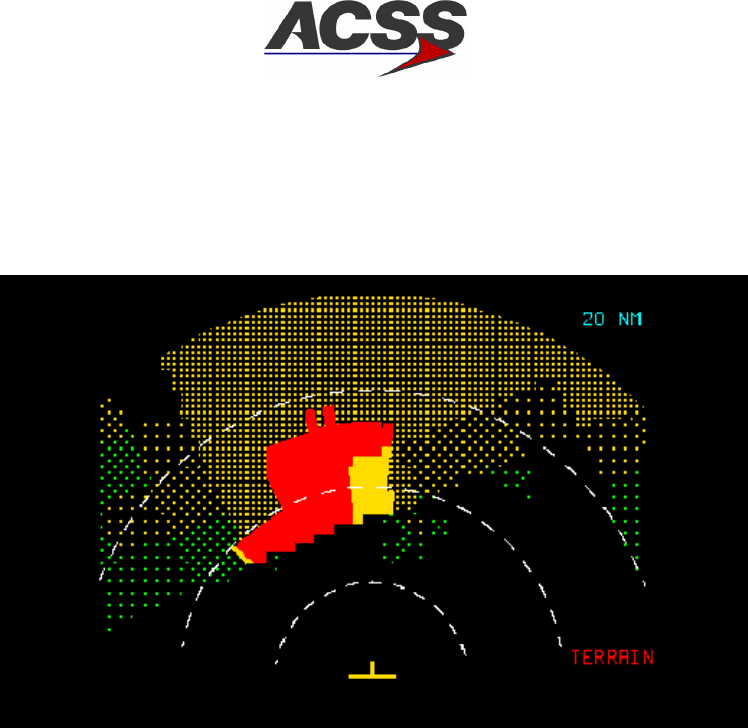
T2CAS / Part No. 9000000
SYSTEM DESCRIPTION AND INSTALLATION MANUAL
34-43-20 15 Feb 2003
Use or disclosure of information on this page is subject to the restrictions in the proprietary notice of this document.
1--77
In Figure 1--30, the warning alarm is generated through the TAWS display by
highlighting the hazardous area ahead of the aircraft in red and generating a red
”TERRAIN” message on the bottom right of the screen. An aural message is also
played on the flight deck.
Figure 1--30. Terrain Hazard Display Upon A Pull--up Warning
In Figure 1--31, the warning alarm is generated through the TAWS display by
highlighting the hazardous area ahead of the aircraft in red with black X’s and
generating a red ”TERRAIN” message on the bottom right of the screen. An
aural message is also played on the flight deck. The ”pull--up” maneuver will not
allow for a safe clearance with terrain, and the crew has to immediately initiate
an appropriate vertical and/or turning escape maneuver in order to avoid a CFIT
accident.
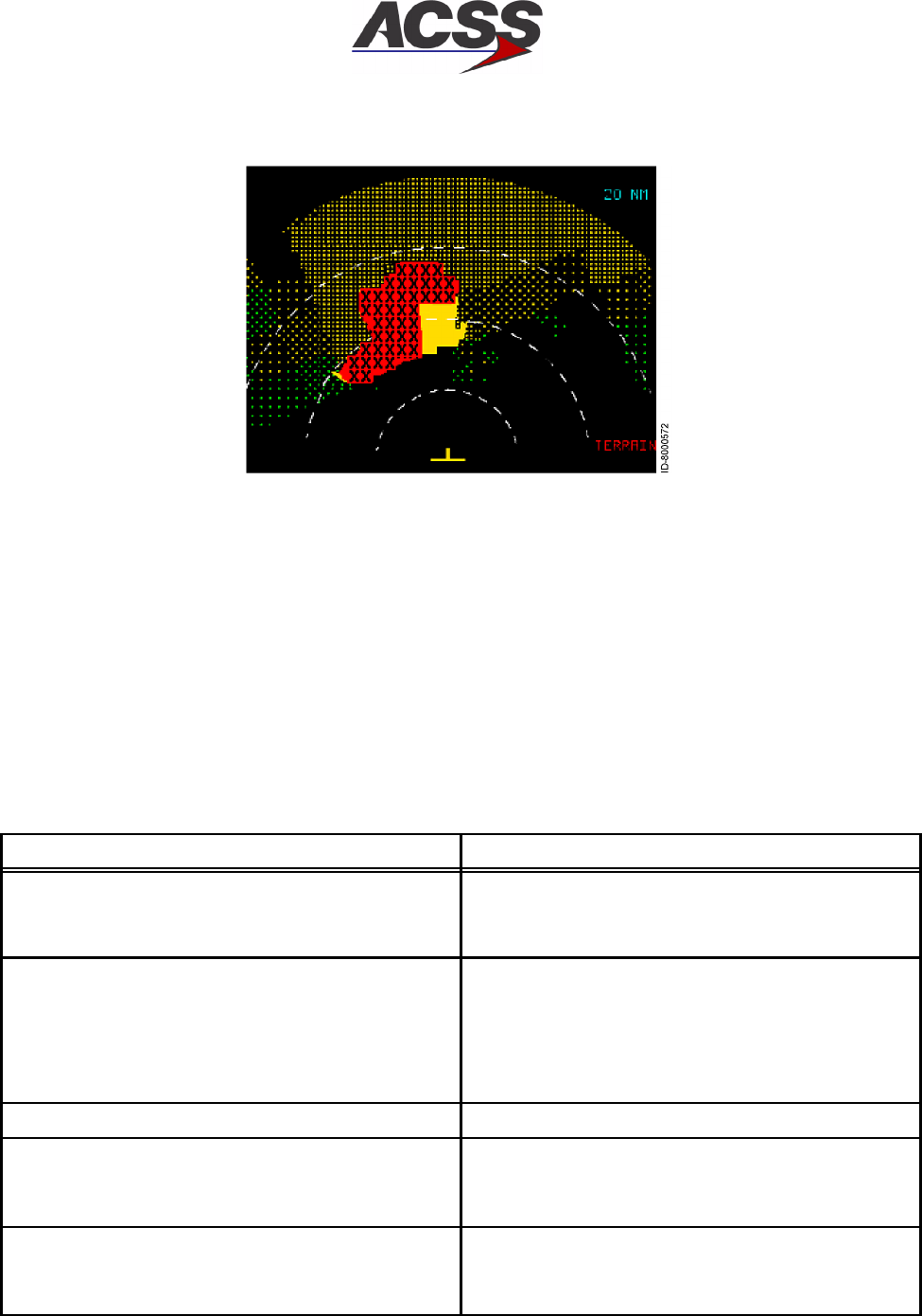
T2CAS / Part No. 9000000
SYSTEM DESCRIPTION AND INSTALLATION MANUAL
34-43-20
15 Feb 2003
Use or disclosure of information on this page is subject to the restrictions in the proprietary notice of this document.
1--78
Figure 1--31. Terrain Hazard Display Upon An Avoid Terrain Warning
(4) TAWS/RWS Aural Messages
Aural alerts can be generated for any of the cautions or warnings generated by the
TAWS and RWS functions. The specific messages are selectable from a list of
several options. Additionally, the T2CAS can be configured to play the voices in
either a male voice or a female voice. The list of selectable aural alerts is shown in
Table 1--13.
Table 1 -- 13. TAWS/RWS Aural Alerts
Condition Selectable Aural Alerts
CPA Caution “Terrain Ahead”
or
“Terrain Caution”
CPA Warning -- Pull up “Terrain Ahead, Pull Up”
or
“Terrain, Terrain, Pull Up, Pull Up”
or
Whoop Whoop, “Pull Up”
CPA Warning -- Avoid Terrain “Avoid Terrain”
Mode 1 Caution Whoop Whoop, “Pull Up”
or
“Pull Up, Pull Up”
Mode 1 Warning Whoop, Whoop, “Pull Up”
or
“Pull Up, Pull Up”
T2CAS / Part No. 9000000
SYSTEM DESCRIPTION AND INSTALLATION MANUAL
34-43-20 15 Feb 2003
Use or disclosure of information on this page is subject to the restrictions in the proprietary notice of this document.
1--79
Table 1 -- 13. TAWS/RWS Aural Alerts(cont)
Condition Selectable Aural Alerts
Mode 2 Caution “Terrain, Terrain”
Mode 2 Warning Whoop Whoop “Pull Up”
or
“Pull Up, Pull Up”
Mode 3 Caution “Don’t Sink, Don’t Sink”
Mode 4 Caution “Too Low Terrain”
or
“Too Low Flaps”
or
“Too Low Gear”
Mode 5 Caution “Glideslope”
Bank Angle Alert “Bank Angle, Bank Angle”
Windshear Caution Nothing
or
“Caution Windshear”

T2CAS / Part No. 9000000
SYSTEM DESCRIPTION AND INSTALLATION MANUAL
34-43-20
15 Feb 2003
Use or disclosure of information on this page is subject to the restrictions in the proprietary notice of this document.
1--80
Table 1 -- 13. TAWS/RWS Aural Alerts(cont)
Condition Selectable Aural Alerts
Windshear Warning “Windshear Windshear Windshear”
or
siren “Windshear Windshear Windshear”
Callouts “Minimums Minimums”
“Minimums”
“Decision Height”
“Unknown Decision Height”
“Approaching Minimums”
“Approaching Decision Height”
“One thousand”
“Five Hundred”
500 ft. tone
“Four Hundred”
“Three Hundred”
“Two Hundred”
“One Hundred”
100 ft tone
“Eighty”
“Sixty”
“Fifty”
“Forty”
“Thirty Five”
35 ft. tone
“Thirty”
“Twenty”
20 ft. tone
“Ten”

T2CAS / Part No. 9000000
SYSTEM DESCRIPTION AND INSTALLATION MANUAL
34-43-20 15 Feb 2003
Use or disclosure of information on this page is subject to the restrictions in the proprietary notice of this document.
1--81
(5) Operating Procedures
Basic TAWS/RWS operating procedures on the ground include pre--flight test,
TAWS/RWS activation before takeoff, and TAWS/RWS deactivation after landing.
In--flight procedures are contained in the pilot’s manual.
(a) Pre--Flight Test
The Standard Self Test is performed by activating either the CMC self test or the
self test discrete input (RTP--10E = GND). The Standard Self Test can occur
while on the ground or while in the airborne state.
Upon activating the Standard Self Test the following will occur:
The Standard Self Test will not be initiated if a TAWS alert is present when
either the CMC self test or the self test discrete input is activated.
If the T2CAS unit has the windshear function enabled, the following aural
annunciation will occur:
”TERRAIN AWARENESS AND WINDSHEAR TEST START”
If the T2CAS unit does not have the windshear function enabled, the
following aural annunciation will occur:
”TERRAIN AWARENESS TEST START”
During the Standard Self Test the following will occur:
All discrete outputs implemented within a specific aircraft installation will be
tested for over current and output voltage levels by activating the output for
1.5 seconds (±100 milliseconds), then deactivating the output for 1.5
seconds (±100 milliseconds), and then re--activating the output for 1.5
seconds (±100 milliseconds). Any faults found will be recorded in the
T2CAS unit’s non--volatile memory.
The T2CAS unit will verify the following functional areas in accordance with
Figure 1--32.
•Aircraft Personality Module (APM)
•Terrain Database CRC
•External System Inputs
•Internal TAWS Parameters
•Internal GPS Parameters (if installed)
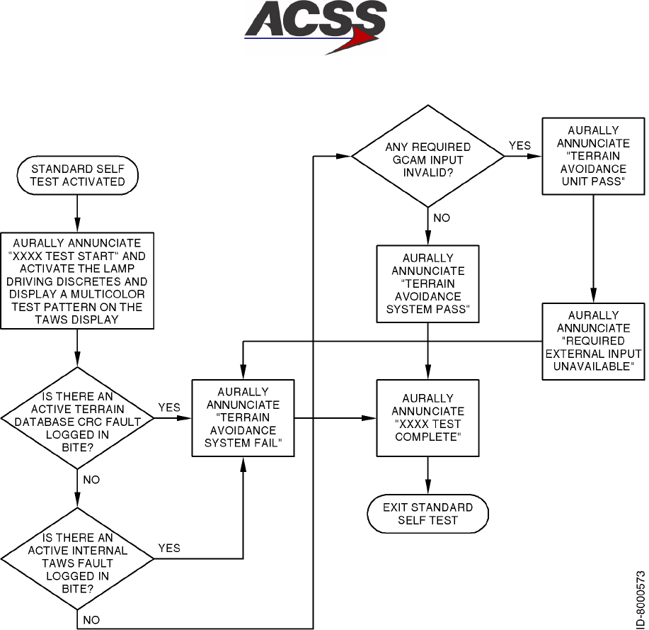
T2CAS / Part No. 9000000
SYSTEM DESCRIPTION AND INSTALLATION MANUAL
34-43-20
15 Feb 2003
Use or disclosure of information on this page is subject to the restrictions in the proprietary notice of this document.
1--82
Figure 1--32. Standard Self--Test of TAWS/Windshear Functional Areas
T2CAS / Part No. 9000000
SYSTEM DESCRIPTION AND INSTALLATION MANUAL
34-43-20 15 Feb 2003
Use or disclosure of information on this page is subject to the restrictions in the proprietary notice of this document.
1--83
ID--8000574
TST PTRN
HOLD SLF TST
TO VIEW EXTENDED
NN2233
445566
CCPPAA
Figure 1--33. TAWS Display Test Pattern
The T2CAS unit will display a multicolor test pattern on both the captain’s and
first officer’s TAWS displays. Figure 1--33 shows a typical multicolor test pattern.
NOTE: Each number in Figure 1--33 represents a texture terrain image slice (2
through 6) as well as the Pull Up area texture (P), avoid terrain area
texture (A), and caution area texture (C) as defined in the ASDB SRS,
Airplane Personality Module. Slice 1 is black in color therefore it is
camouflaged into the background
The T2CAS unit will interrupt the Standard Self Test when any of the following
alerts occur:
•“WINDSHEAR, WINDSHEAR, WINDSHEAR”
•“TERRAIN AHEAD, PULL UP”
•“TERRAIN TERRAIN, PULL UP PULL UP”
•“≈≈ PULL UP”
•“TERRAIN AHEAD”
•“TERRAIN CAUTION”
•“AVOID TERRAIN”
•“PULL UP, PULL UP”
•“TERRAIN, TERRAIN”
•“SINK RATE, SINK RATE”

T2CAS / Part No. 9000000
SYSTEM DESCRIPTION AND INSTALLATION MANUAL
34-43-20
15 Feb 2003
Use or disclosure of information on this page is subject to the restrictions in the proprietary notice of this document.
1--84
•“DON’T SINK, DON’T SINK”
•“TOO LOW, TERRAIN”
•“TOO LOW, GEAR”
•“TOO LOW, FLAPS”
•“GLIDESLOPE”
NOTE: “≈≈” designates a pair of varying tones from 400 to 800 Hz; where
each tone is 0.3 seconds in duration, separated by 0.1 seconds, and at
the end of the pair there is 0.1 seconds of silence.
NOTE: The aural annunciations listed above will depend on the Operator
Selectable Options chosen during installation of the T2CAS unit.
Upon completion of the Standard Self Test the following will occur:
If the T2CAS unit has the windshear function enabled and the APM and
Terrain Database and Internal system and Internal GPS self tests have
passed, the following aural annunciation will occur:
”TERRAIN AWARENESS AND WINDSHEAR TEST PASSED”
If the T2CAS unit does not have the windshear function enabled and the
APM and Terrain Database and Internal system and Internal GPS self tests
have passed, the following aural annunciation will occur:
”TERRAIN AWARENESS TEST PASSED”
If the T2CAS unit does not have the windshear function enabled and the
APM or Terrain Database or Internal system or Internal GPS self tests have
failed, the following aural annunciation will occur:
”TERRAIN AWARENESS AND WINDSHEAR TEST COMPLETE”
If the T2CAS unit does not have the windshear function enabled and the
APM or Terrain Database or Internal system or Internal GPS self tests have
failed, the following aural annunciation will occur:
”TERRAIN AWARENESS TEST COMPLETE”
This information is summarized in the Table 1--14.
Table 1--14. Aural Annunciation
Terrain Awareness
and Windshear
Test Passed
Terrain Awareness
and Windshear
Test Complete
Terrain Awareness
Test Passed
Terrain Awareness
Test Complete
Windshear
Enabled?
YES YES NO NO
APM or Terrain
Database or
Internal System or
Internal GPS Fail?
NO YES NO YES

T2CAS / Part No. 9000000
SYSTEM DESCRIPTION AND INSTALLATION MANUAL
34-43-20 15 Feb 2003
Use or disclosure of information on this page is subject to the restrictions in the proprietary notice of this document.
1--85
(b) TAWS/RWS Mode Activation
The TAWS/RWS is activated upon Aircraft Power Up and becomes available
when parameters needed for normal operation of the TAWS/RWS functions are
available.
(c) TAWS/RWS Mode Deactivation
The TAWS/RWS becomes deactivated upon Aircraft Power Down. Specific
TAWS/RWS functions can become unavailable if an Internal or External
parameter needed for normal operation of the TAWS/RWS functions are
unavailable or invalid.
The TAWS Predictive CPA Modes may become deactivated upon the selection
of the “Terrain Inhibit” switch. The purpose of the “Terrain Inhibit” switch is to
allow the aircraft to operate without nuisance or unwanted warnings at airports
that are not in the system database. Additionally, there may be some “VFR only”
airports where unique terrain features are in close proximity to the runway. The
“Terrain Inhibit” switch should NOT be engaged for normal operations.

T2CAS / Part No. 9000000
SYSTEM DESCRIPTION AND INSTALLATION MANUAL
34-43-20
15 Feb 2003
Use or disclosure of information on this page is subject to the restrictions in the proprietary notice of this document.
1--86
Blank Page

T2CAS / Part No. 9000000
SYSTEM DESCRIPTION AND INSTALLATION MANUAL
34-43-20 15 Feb 2003
Use or disclosure of information on this page is subject to the restrictions in the proprietary notice of this document.
2--1
MECHANICAL INSTALLATION
1. General
This section contains information on how and where to mount each component of the T2CAS
system. For new installations, plan installation in two stages. First, determine the location of
the LRUs in the aircraft. Next, determine the length of RF and electrical interconnections for
selected locations.
NOTE:The RT--95X CFDS/CMC capability has not been demonstrated as part of an
installed system. The CFDS/CMC capability must be demonstrated on the aircraft to
the appropriate certification authorities before the CFDS/CMC functionality may be
used.
2. Equipment and Materials
For new T2CAS installations, refer to Table 1--1 for RCZ--852 Transponder Installation Kit
information and Table 1--2 for mounting tray information. For all other components, refer to
the applicable Outline and Installation drawing in this section for mounting information. The
Outline and Installation drawings show connector and connector contact pin/socket part
number information, where applicable.
3. Mechanical Installation Design
NOTE:To assure proper grounding of the T2CAS system, the aircraft surface to which all
mountings or units are attached must be clean bare metal. Mount to the airframe
with a resistance of 5 milliohms or less.
A. TT--950/951/952 T2CAS Computer Unit Provisions
Mechanical installation data for the TT-- 950/952 T2CAS Computer Unit (6--MCU) is
shown in Figure 2--6. Data for the TT--951 T2CAS Computer Unit (4--MCU) is shown in
Figure 2--7.
The computer unit can be mounted in any convenient location in the aircraft; however, it
must be located so as to maintain an antenna coaxial cable insertion loss of 2.5 ±0.5 dB
in accordance with DO--185. This is approximately within 50 feet of the antenna unless
low loss coaxial cable is used. Top and bottom coaxial delay timing differences can be
compensated for by use of the antenna delay program pins.

T2CAS / Part No. 9000000
SYSTEM DESCRIPTION AND INSTALLATION MANUAL
34-43-20
15 Feb 2003
Use or disclosure of information on this page is subject to the restrictions in the proprietary notice of this document.
2--2
The TT--950/952 T2CAS Computer Unit is mounted in an ARINC 600 6--MCU mounting
tray. The computer unit requires external cooling air in accordance with ARINC 600 or
ARINC 404 to maintain the highest possible Mean Time Between Failures (MTBF). In
those installations where this is not available, a mounting tray with an integral fan is
required.
The TT--951 T2CAS computer unit is mounted in an ARINC 600 4--MCU mounting tray.
This unit contains an internal temperature controlled fan, so it does not require any
external cooling.
The T2CAS computer tray connector is RADIALL part number NSXN3P357X0001 (other
Brands are available, but the RADIALL is preferred). This tray connector does not come
with contacts so approximately 150 each RADIALL part number 620--200, 22 gauge pins
will be needed as well.
The required contacts for the LBP insert depend on if the computer is to be powered with
+28 Vdc or 115 Vac and if a 115 Vac cooling fan will be connected when the computer is
powered with 115 Vac. Note that there is no output pins to support a +28 Vdc cooling fan.
B. Airplane Personality Module Provisions
Reference Figure 2--5 for the mechanical installations of the ACSS T2CAS APM. The
APM can be mounted to existing aircraft structure or can be mounted to the ACSS APM
mounting bracket that is secured to the aft side of the T2CAS computer tray connector,
reference Figure 2--5 (Sheet 2). If the Customer specifies the ACSS APM mounting
bracket, an APM bracket sub kit will be provided for the Customer’s T2CAS installations.
C. Antenna Provisions
The T2CAS TCAS top directional antenna should, ideally, be the most forward antenna on
the top of the aircraft and should be located as close to the longitudinal centerline as
possible. See Figure 2--10. A 5--degree tilt angle is allowed laterally, with 2--degree
positive and 5--degree negative tilt angles allowed longitudinally. See Figure 2--11.
If a bottom directional antenna is used, it should also be the most forward antenna on the
fuselage bottom. Tilt angle allowances are the same as on the top antenna. A bottom
omnidirectional antenna need not be the most forward antenna, but it should be
separated by at least 20--inches from any other L--band antenna.
Since the bottom antenna may be either a directional (standard) or an omnidirectional
(optional) antenna, dual notation is shown in the wiring diagram. Only one coax cable is
needed for an omnidirectional antenna installation.
(1) Directional Antenna Installation
The top directional antenna mounting and installation data is given in Figure 2--12.
Figure 2--12 contains the maximum radius dimensions for the various curved antenna
base part number units, the number of aircraft mounting holes and the length of the
connector extension for the various part number units. The antenna must be
electrically bonded (less than 5.0 milliohms bonding resistance) to the airframe to
provide a ground plane for the antenna elements.

T2CAS / Part No. 9000000
SYSTEM DESCRIPTION AND INSTALLATION MANUAL
34-43-20 15 Feb 2003
Use or disclosure of information on this page is subject to the restrictions in the proprietary notice of this document.
2--3
The directional antenna must be separated by a least 30--inches from any other
L--band antenna, and 60--inches is preferred. If a bottom directional antenna is used,
it should be the most forward antenna on the fuselage bottom with tilt angle
allowances the same as for a top mounted antenna.
An O--ring (included with the directional antenna) is required to be installed between
the directional antenna and the aircraft fuselage. The Navy Aeronautical Standard
part number for the O--ring is NAS 1611--240. The ACSS part number for the O--ring
is 4000171--240.
NOTE: For directional antennas, ACSS Part No. 7514060--90X, the customer must
provide an adapter plate for mounting to the aircraft. The antenna base
plate, to which the adapter must mate, is detailed in Figure 2--12.
Directional antennas, ACSS Part No. 7514081--9XX, come with a
preinstalled adapter plate.
(2) Omnidirectional Antenna Installation
The bottom omnidirectional antenna is a standard ATC type antenna. It should be
qualified to TSO C119b and be DC grounded per MIL--A--90941, B--5087B. All
L--band antennas must be separated by at least 20--inches. Only one coax cable is
required for installation.
The omnidirectional antenna is not supplied by ACSS. To install, follow the
manufacturer’s installation instructions.
D. GPS Antenna and Coax Provisions
Reference Figure 2--4 for the mechanical installations of the ACSS GPS Antenna. The
GPS installation design will consist of an A429 interface to the GPS sensor if the signal is
available, otherwise the T2CAS internal GPS module will be required. The installation
then consists of the installation of a GPS antenna and the coax cable to the T2CAS unit,
LBP pin 13.
Where the internal module is required, the T2CAS GPS Installation Data Package
includes the GPS antenna mounting structures provisions and all of the coax details to
secure the coax to the airframe and connect the T2CAS GPS antenna with the T2CAS
computer’s LBP pin 13.
The minimum combined coax and connector insertion loss between the GPS antenna’s
output and the T2CAS computer’s GPS input port is equal to the maximum preamplifier
gain minus 29 dB. The maximum coax loss between the GPS antenna’s output and the
T2CAS computer’s GPS input port is equal to the minimum preamplifier gain minus 12.5
dB.
T2CAS / Part No. 9000000
SYSTEM DESCRIPTION AND INSTALLATION MANUAL
34-43-20
15 Feb 2003
Use or disclosure of information on this page is subject to the restrictions in the proprietary notice of this document.
2--4
This is summarized with several examples in the Table 2--1 below, assuming 4 unique
installations.
Table 2--1. Coax Cable/Connector Loss
Assumed
Antenna
Gain (dB)
Minimum
Cable And
Connector
Loss(dB)
Maximum Cable
And Connector
Loss(dB)
Cable
Length
(feet)
Recommended
CableType(and
loss)
(Cable Length (feet)x
Loss) + Connector
Loss= Cable and
Connector Loss
30 30 -- 29 = 1 30 -- 12.5 = 16.5 10 311601 (0.11 db/ft) (0.11*10)+1=2.1
30 30 -- 29 = 1 30 -- 12.5 = 16.5 100 311601 (0.11 db/ft) (0.11 * 100) + 1 = 12
26 26<29=>0 26 -- 12.5 = 13.5 10 311601 (0.11 db/ft) (0.11*10)+1=2.1
26 26<29=>0 26 -- 12.5 = 13.5 100 311601 (0.11 db/ft) (0.11 * 100) + 1 = 12
In the above examples, the antenna gain and assumed losses effectively stay within the
desired minimum and maximum ranges.
High--quality coaxial cables should be used because a mismatch in impedance, possible
with lower quality cables, produces reflections in the cable that increase signal loss.
Losses due to cable mismatch should be considered in the maximum cable loss budget.
The coax must meet FAR part 25 specifications for environmental conditions.
Recommended antenna mounting location
(1) The GPS antenna should be installed close to aircraft centerline with minimum
deviation from the aircraft level horizontal position. The antenna location is on the top
side, front half of the aircraft fuselage to minimize the shadowing effect of the vertical
stabilizer and wings.
(2) The GPS antenna should be installed at least 39 inches (1 meter) away from any
other non L--band or L--band except as mentioned below.
(3) If a SATCOM transmitting antenna is installed, the GPS antenna should be located a
minimum of 160 inches (4.064 meters) away.
(4) For a dual GPS antennae installation, the separation should be a minimum of 12
inches.
(5) If a TCAS or VHF communication transmitting/receiving antenna is installed, the GPS
antenna should be located a minimum of 48 inches (1.219 meters) away.

T2CAS / Part No. 9000000
SYSTEM DESCRIPTION AND INSTALLATION MANUAL
34-43-20 15 Feb 2003
Use or disclosure of information on this page is subject to the restrictions in the proprietary notice of this document.
2--5
E. TCAS Control Panel Provisions
Mechanical installation data for a typical Gables GXXXX Series ATC/TCAS control panel
is shown in Figure 2--14.
It should be noted that various other types of controllers (Radio Management Units or
EFIS Display Controllers) can be used to control the TCAS display. If a controller other
than a ACSS ATC/TCAS control panel is used, refer to that particular unit’s manual for
installation data.
F. TAWS/RWS Control Panel Provisions
The TAWS controls can be mounted on a single control panel or they can be discrete
switches individually mounted at a convenient location in the Flight Deck. The TAWS
controls may be part of the electronic display menu selection in installations where TAWS
information is displayed on an EFIS or electronic display.
Figure 2--1 shows the ACSS King Air C90 TAWS control panel/glareshield switch
annunciator installation design. The TERR and WXR select switches shown are
momentary but alternate action switches are also supported. The terrain INHIBIT or
OVRD switches are alternate action switches and are typically gaurded.
The T2CAS TAWS control/annunciator installation design will vary depending on the Flight
deck configuration and available space.
G. VSI/TRA Provisions
Mechanical installation data for the VSI/TRA display is shown in Figure 2--15. The
VSI/TRA is usually used as a direct replacement for the existing 3--ATI form VSI indicator
currently mounted in the Flight Deck. Replacement of the installation clamp may be
necessary if the previous clamp is less than 2--inches deep. Some older aircraft clamps
do not provide sufficient mechanical support.
If a Thales VSI/TRA is used as the TCAS display source, and an Air Data Computer is not
available to provide vertical speed signals to the display, a static line can be run directly
into the Thales VSI/TRA from a static pneumatic input.
H. TAWS Terrain Hazard Display Provisions
ARINC 708A and ARINC 429 WXR display and EFIS interfaces are supported. T2CAS’
dual--independent terrain hazard display I/O supports dual ARINC 708A and dual ARINC
429 terrain hazard display systems. Figure 2--2 shows TAWS Dual Terrain hazard display
annunciator switch panels and locations that have been used on B757, B767, and
B737--300/400/500 aircraft. Figure 2--3 shows a typical single terrain hazard display
annunciator switch panel.
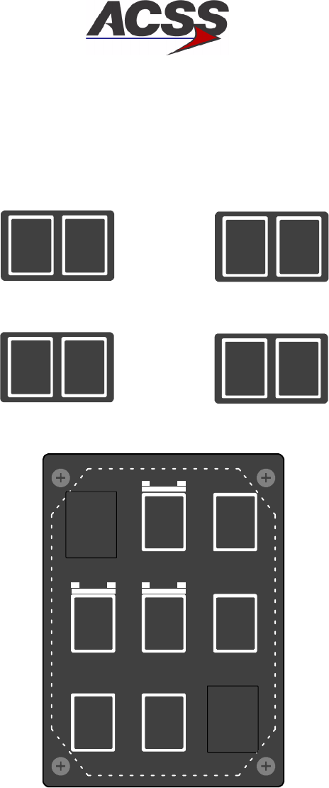
T2CAS / Part No. 9000000
SYSTEM DESCRIPTION AND INSTALLATION MANUAL
34-43-20
15 Feb 2003
Use or disclosure of information on this page is subject to the restrictions in the proprietary notice of this document.
2--6
NORM
CMPST
TERR
WXR
TERR
N/A
GPWS
N/A
TERR
TERR
CAPTAIN’S AND FIRST OFFICER’S GLARESHIELD
SWITCH ANNUNCIATORS. (ANNUNCIATOR TEST ON)
CAPTAIN’S AND FIRST OFFICER’S GLARESHIELD
SWITCH ANNUNCIATORS. (NORMAL FLIGHT CONDITION)
ANNUNCIATOR TEST ON. (WHITE DASHES ARE
HIDDEN LINES SHOWING EXISTING 3 ATI CUTOUT)
ID--8000576
FLAP
OVRD
GS
OVRD
STEEP
APPR
UP
DOWN
TERR
N/A
GPWS
N/A
ON ON ON
TERR
INHIBIT
TERR
ON
TERR
Figure 2--1. ACSS King Air C90 TAWS Control Panel/Glareshield Switch Annunciators
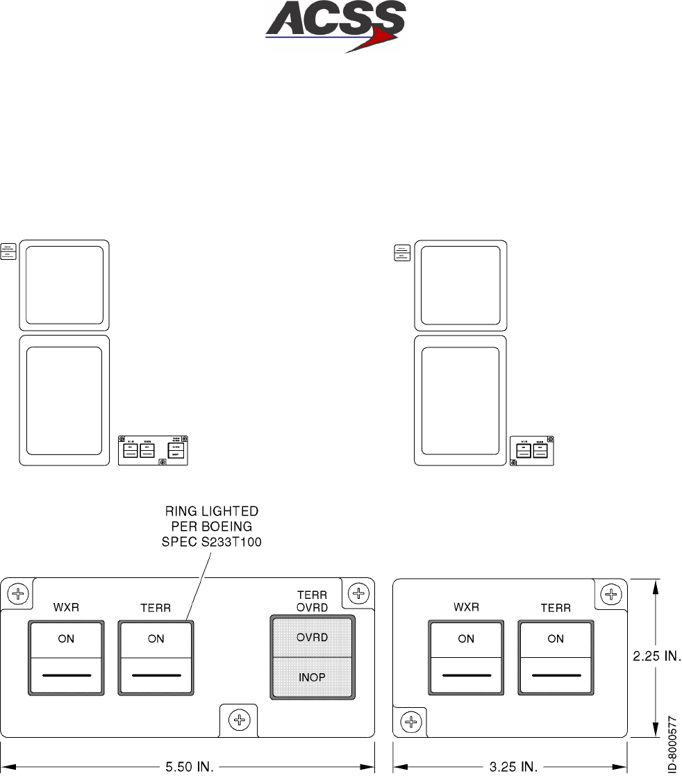
T2CAS / Part No. 9000000
SYSTEM DESCRIPTION AND INSTALLATION MANUAL
34-43-20 15 Feb 2003
Use or disclosure of information on this page is subject to the restrictions in the proprietary notice of this document.
2--7
Figure 2--2. Typical Five--Button B737/757/767 Annunciator Switch Panels
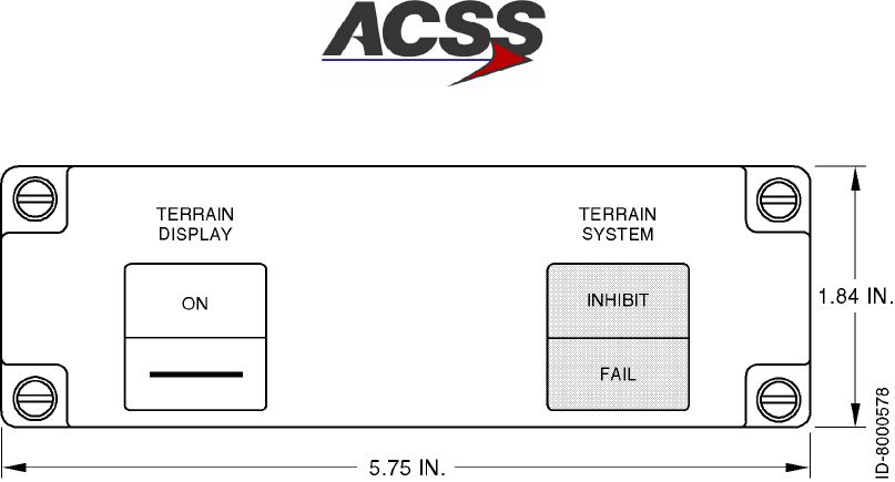
T2CAS / Part No. 9000000
SYSTEM DESCRIPTION AND INSTALLATION MANUAL
34-43-20
15 Feb 2003
Use or disclosure of information on this page is subject to the restrictions in the proprietary notice of this document.
2--8
Figure 2--3. Typical Single Terrain Hazard Display Annunciator Switch Panel
I. Transponder Provisions
This paragraph contains the mechanical installation data for the ACSS Mode S Data Link
Transponder, Part No. 7517800--XXYYY and ACSS Diversity Mode S Transponder, Part
No. 7510700--850. It also contains provisions for installing the ATC transponder
antennas.
(1) Mode S Data Link Transponder Provisions
Mechanical installation data for the ACSS Mode S Data Link Transponder, Part No.
7517800--XXYYY is shown in Figure 2--8. The transponder can be mounted in any
convenient location in the aircraft; however, it should be mounted within 30 feet of the
antennas unless low loss coaxial cable is used to maintain a worst case loss of 3dB
per ARINC 718. Top and bottom antenna coaxial run length differences can be
compensated for by use of the antenna delay program pins on the transponder. The
unit can utilize external cooling air in accordance with ARINC 600 or ARINC 404 or
operate in convection--cooled environments. The transponder is mounted in an
ARINC 600 4--MCU tray assembly.
(2) Diversity Mode S Transponder Provisions
Mechanical installation data for the ACSS RCZ--852 Diversity Mode S Transponder,
Part No. 7510700--850 is shown in Figure 2--9. The transponder can be mounted in
any convenient location in the aircraft that allows the unit to be upright during normal
flight. The exact location should allow the cabling between the unit, control panel,
and antennas to be as short as possible. The location of the mounting tray (part of
installation kit, Part No. 7510707--968) should allow adequate space for installation
of the transponder, provide reasonable accessibility for servicing, and allow space on
top, sides, and rear of unit for adequate ventilation. The location must also provide a
solid mechanical mount to prevent vibration amplification. The mounting tray should
be electrically bonded to the aircraft frame by a low resistance path of less than 2.5
milliOhms.

T2CAS / Part No. 9000000
SYSTEM DESCRIPTION AND INSTALLATION MANUAL
34-43-20 15 Feb 2003
Use or disclosure of information on this page is subject to the restrictions in the proprietary notice of this document.
2--9
(3) ATC Transponder Antenna Provisions
When installing transponder antennas, a TSO’d antenna should be selected. The
antenna must be vertically polarized and operate in the frequency range of 960 to
1220 MHz. Antenna impedance must be 50 ohms. Selection of a grounded or
lightning protected type antenna is required to pass the transponder bite continuity
detection circuitry, if enabled.
In dual transponder antenna installations it is important to provide adequate isolation
from each other to prevent receiver front--end damage. A 20--inch minimum
separation of Mode S antennas from other L--Band antennas, including TCAS
antennas, must be maintained. The maximum cable length for RG--214/U is 30 feet
(9.144 meters). Allow adequate cable length so bends in cable have a minimum
3--inch (76 mm) radius. Selection of coax cable assemblies with moisture barrier
protection is highly recommended to minimize the effects of humidity and corrosion.
When ATC antennas are installed, the mounting area must provide a solid
mechanical base for the antenna as well as clearance for the connector. A doubler
plate is usually required when the antenna is mounted on an unsupported large
fuselage area. Never weaken aircraft structure for the sake of a good location.
Refer to the aircraft manufacturer’s specifications; reinforcements for antennas are
often built into the aircraft structure.
Doubler plates or shims, if used, must be metallic and shaped to interface the
antenna base with the contour of the aircraft fuselage. ATC antennas are not
supplied by ACSS. All antenna installations should be in accordance with
manufacturer installation instructions.
A weather sealant should be applied around the periphery of the antenna base to
prevent seepage of water and condensation and preclude corrosion. If a sealant or
aerodynamic smoother is used, it should be applied after the antenna has been
bolted down.

T2CAS / Part No. 9000000
SYSTEM DESCRIPTION AND INSTALLATION MANUAL
34-43-20
15 Feb 2003
Use or disclosure of information on this page is subject to the restrictions in the proprietary notice of this document.
2--10
Blank Page
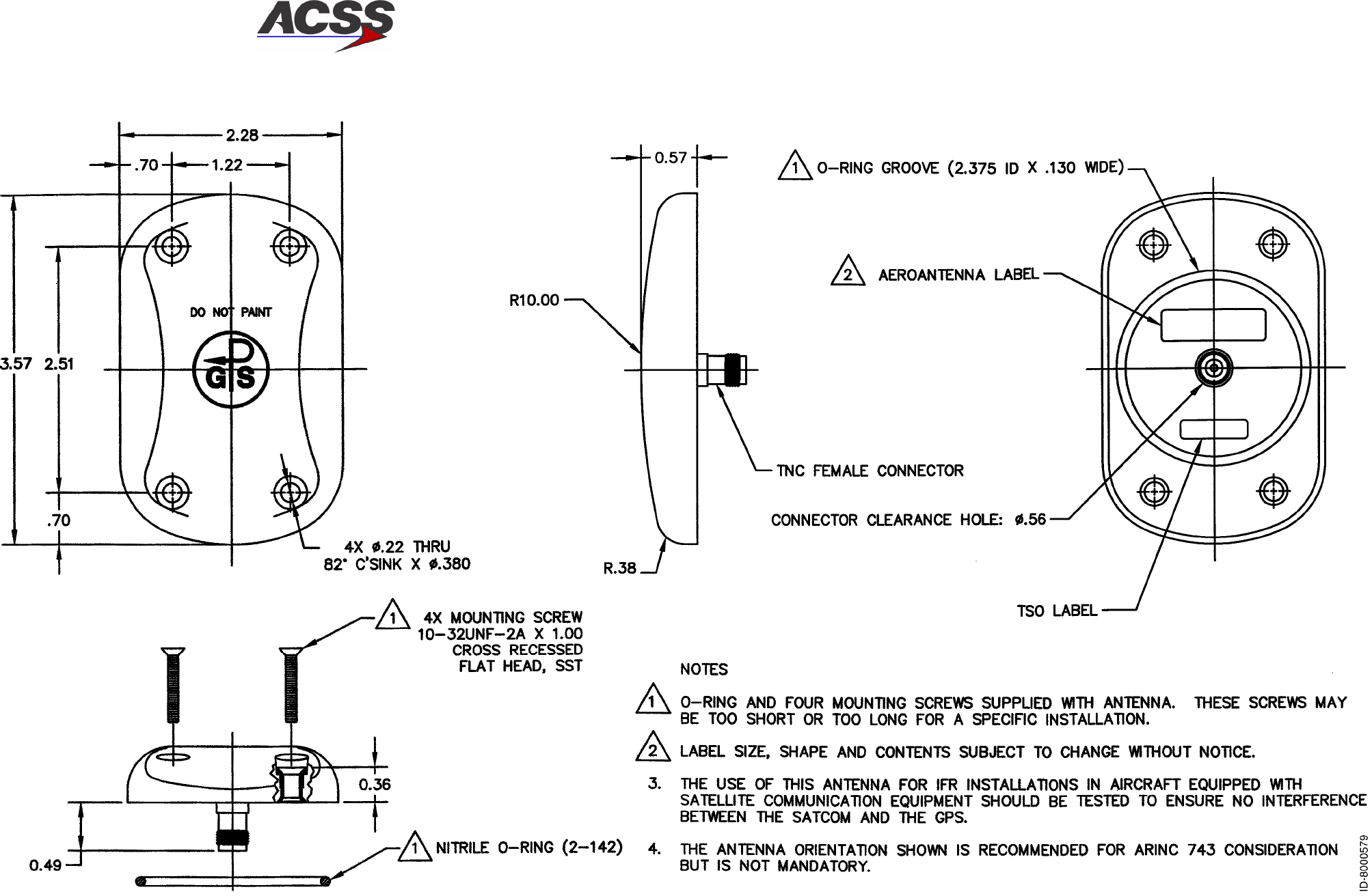
T2CAS / Part No. 9000000
SYSTEM DESCRIPTION AND INSTALLATION MANUAL
34-43-20 15 Feb 2003
Use or disclosure of information on this page is subject to the restrictions in the proprietary notice of this document.
2--11/(2--12 blank)
Figure 2--4. GPS Antenna Outline and Installation Drawing
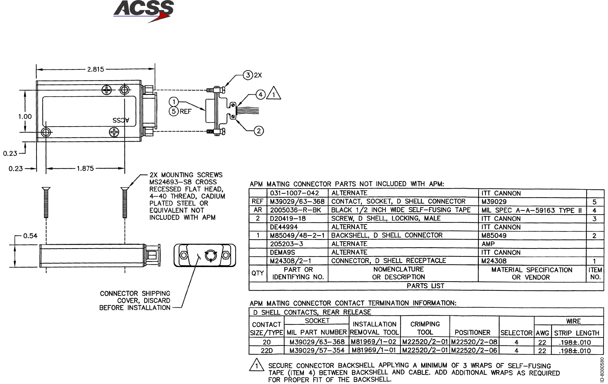
T2CAS / Part No. 9000000
SYSTEM DESCRIPTION AND INSTALLATION MANUAL
34-43-20 15 Feb 2003
Use or disclosure of information on this page is subject to the restrictions in the proprietary notice of this document.
2--13/(2--14 blank)
Figure 2--5 (Sheet 1). APM Outline and Installation Drawings
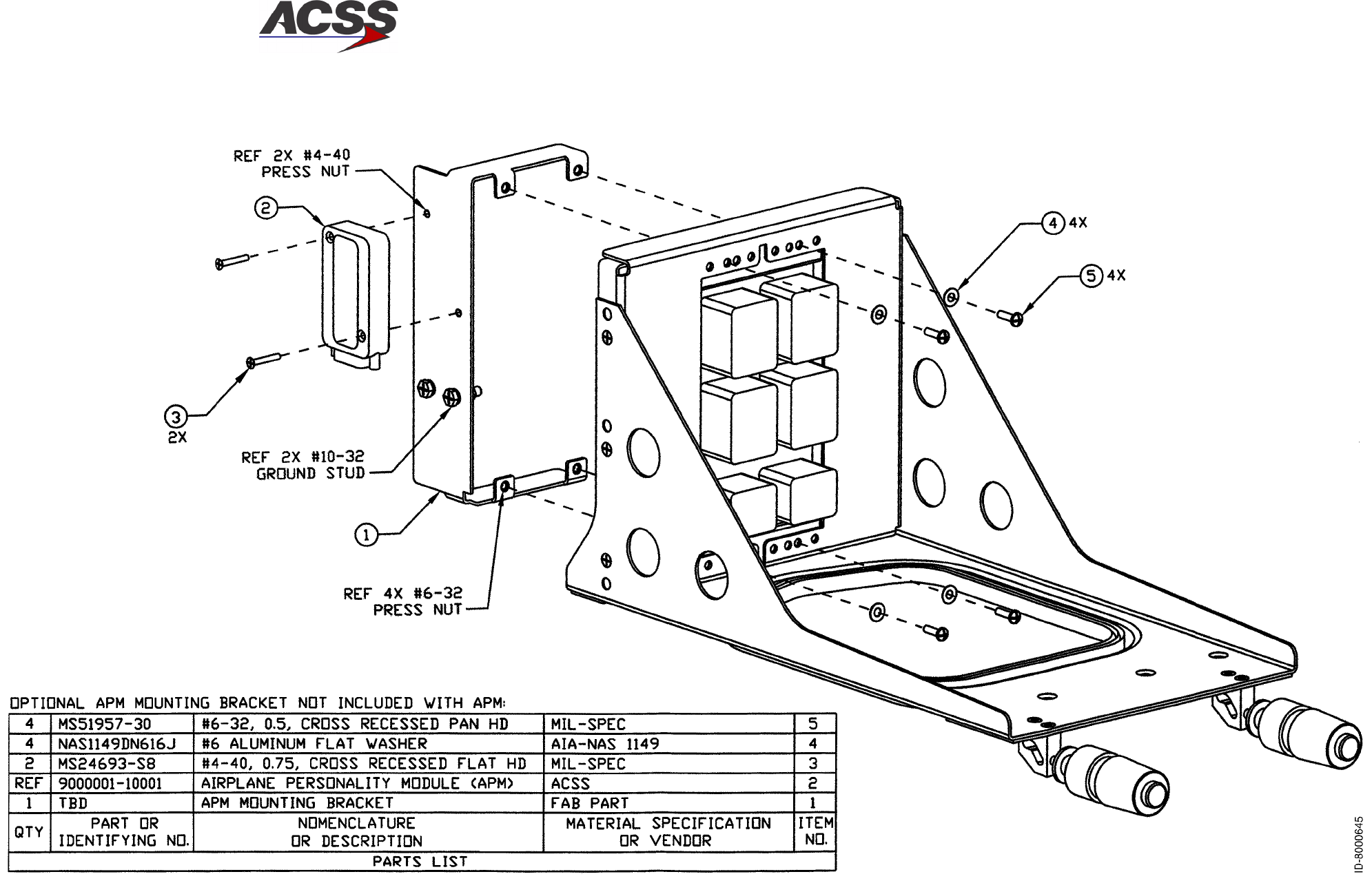
T2CAS / Part No. 9000000
SYSTEM DESCRIPTION AND INSTALLATION MANUAL
34-43-20 15 Feb 2003
Use or disclosure of information on this page is subject to the restrictions in the proprietary notice of this document.
2--15/(2--16 blank)
Figure 2--5 (Sheet 2). APM Outline and Installation Drawings
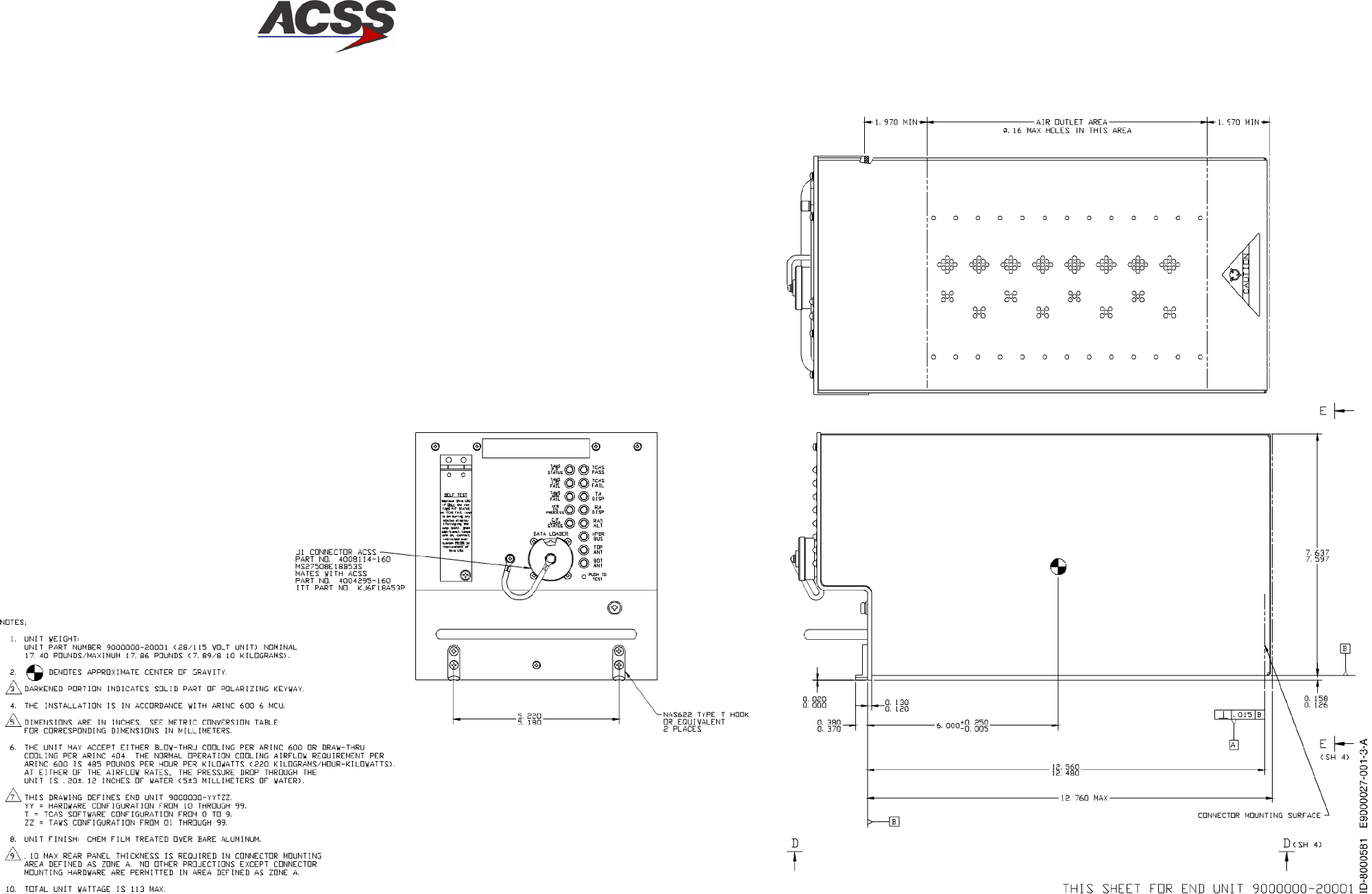
T2CAS / Part No. 9000000
SYSTEM DESCRIPTION AND INSTALLATION MANUAL
34-43-20 15 Feb 2003
Use or disclosure of information on this page is subject to the restrictions in the proprietary notice of this document.
2--17/(2--18 blank)
Figure 2--6 (Sheet 1). TT--950/952 T2CAS Computer Unit Outline and Installation Drawing
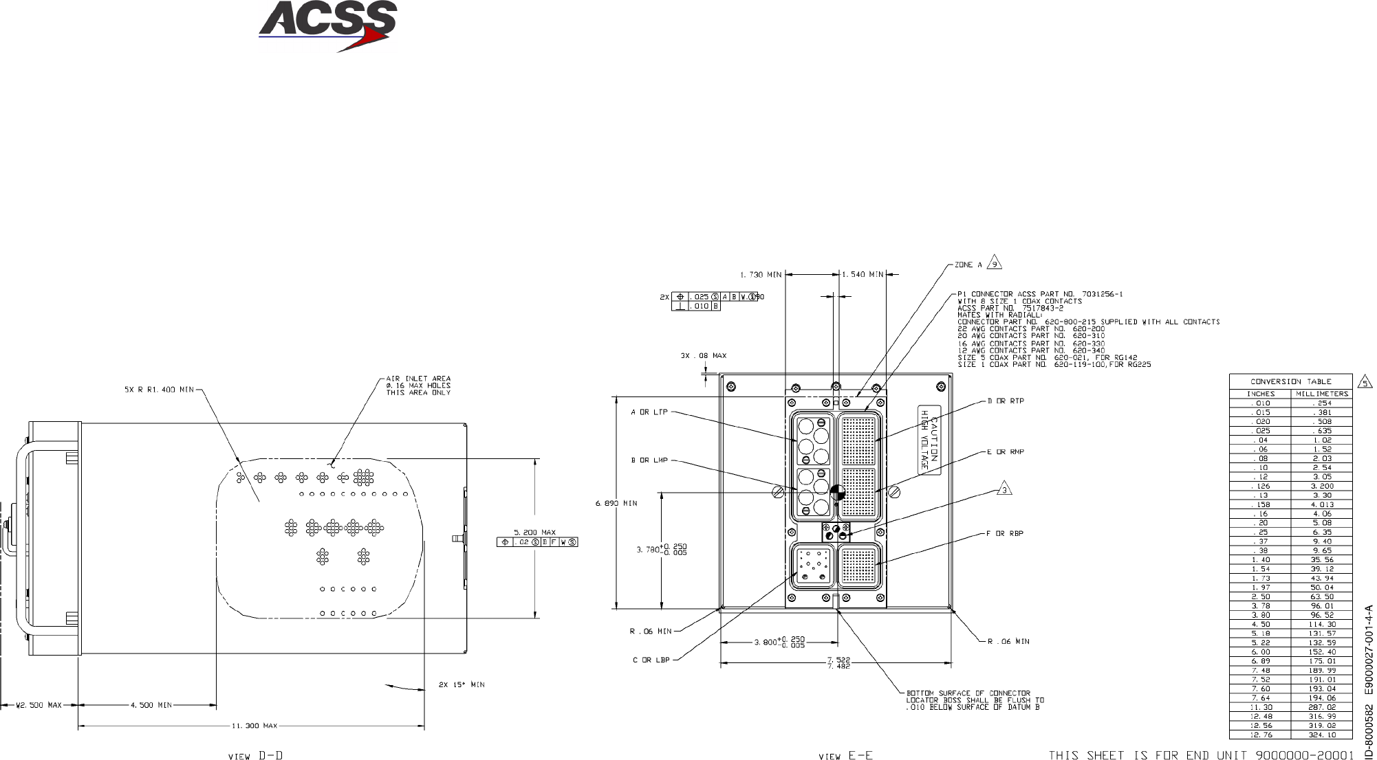
T2CAS / Part No. 9000000
SYSTEM DESCRIPTION AND INSTALLATION MANUAL
34-43-20 15 Feb 2003
Use or disclosure of information on this page is subject to the restrictions in the proprietary notice of this document.
2--19/(2--20 blank)
Figure 2--6 (Sheet 2). TT--950/952 T2CAS Computer Unit Outline and Installation Drawing
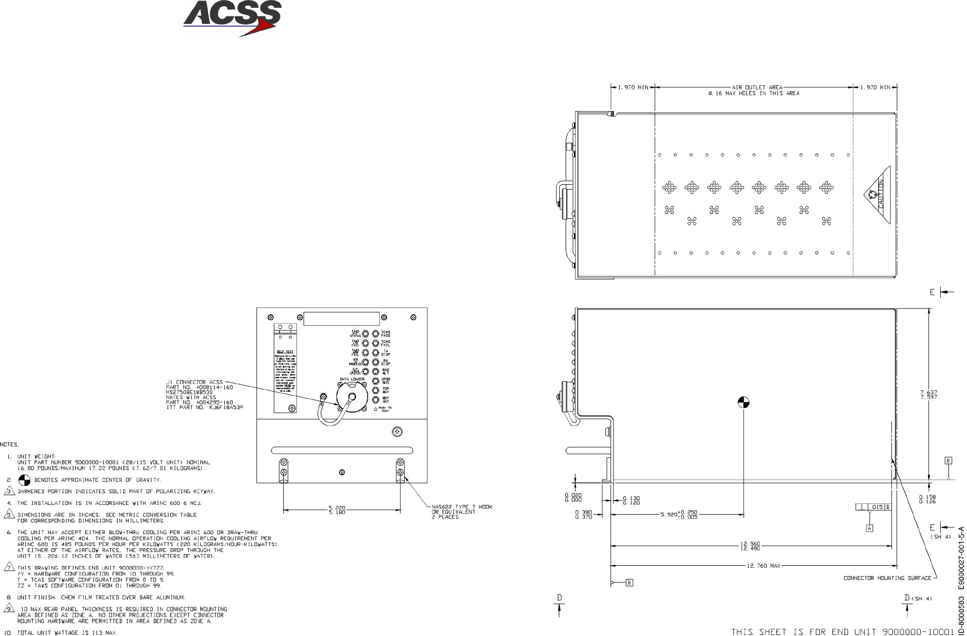
T2CAS / Part No. 9000000
SYSTEM DESCRIPTION AND INSTALLATION MANUAL
34-43-20 15 Feb 2003
Use or disclosure of information on this page is subject to the restrictions in the proprietary notice of this document.
2--21/(2--22 blank)
Figure 2--6 (Sheet 3). TT--950/952 T2CAS Computer Unit Outline and Installation Drawing

T2CAS / Part No. 9000000
SYSTEM DESCRIPTION AND INSTALLATION MANUAL
34-43-20 15 Feb 2003
Use or disclosure of information on this page is subject to the restrictions in the proprietary notice of this document.
2--23/(2--24 blank)
Figure 2--6 (Sheet 4). TT--950/952 T2CAS Computer Unit Outline and Installation Drawing
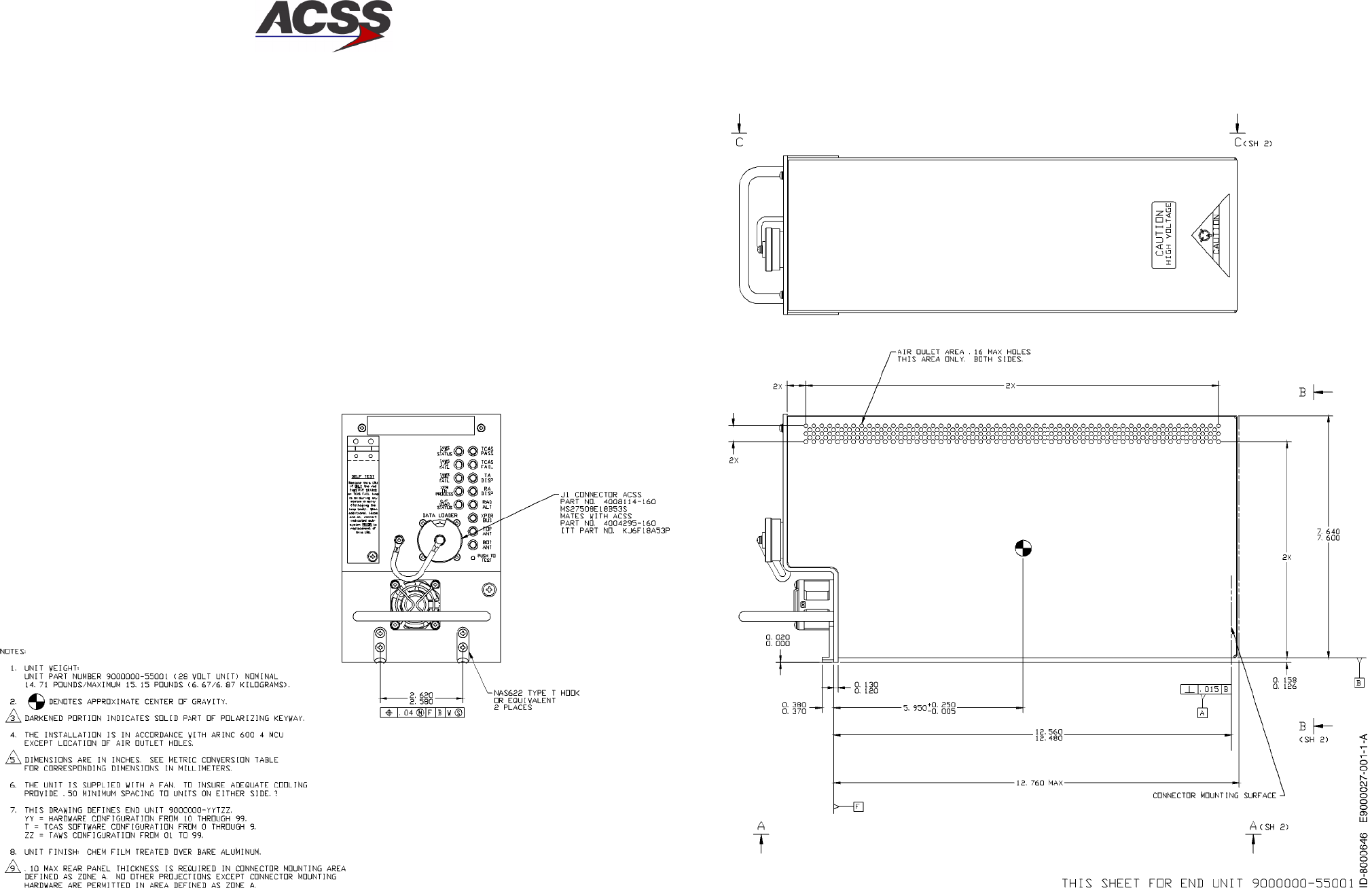
T2CAS / Part No. 9000000
SYSTEM DESCRIPTION AND INSTALLATION MANUAL
34-43-20 15 Feb 2003
Use or disclosure of information on this page is subject to the restrictions in the proprietary notice of this document.
2--25/(2--26 blank)
Figure 2--7 (Sheet 1). TT--951 T2CAS Computer Unit Outline and Installation Diagram
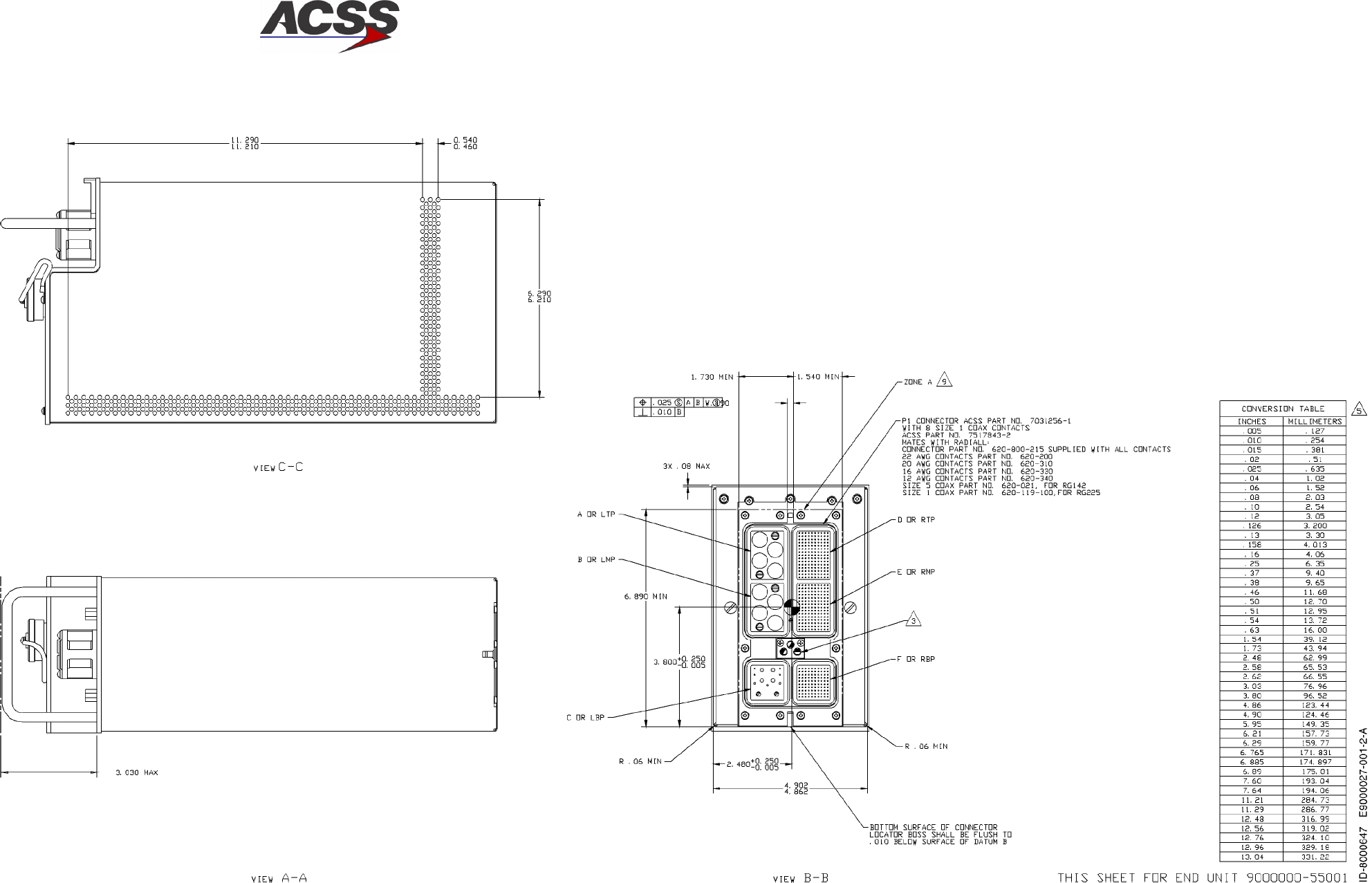
T2CAS / Part No. 9000000
SYSTEM DESCRIPTION AND INSTALLATION MANUAL
34-43-20 15 Feb 2003
Use or disclosure of information on this page is subject to the restrictions in the proprietary notice of this document.
2--27/(2--28 blank)
Figure 2--7 (Sheet 2). TT--951 T2CAS Computer Unit Outline and Installation Diagram
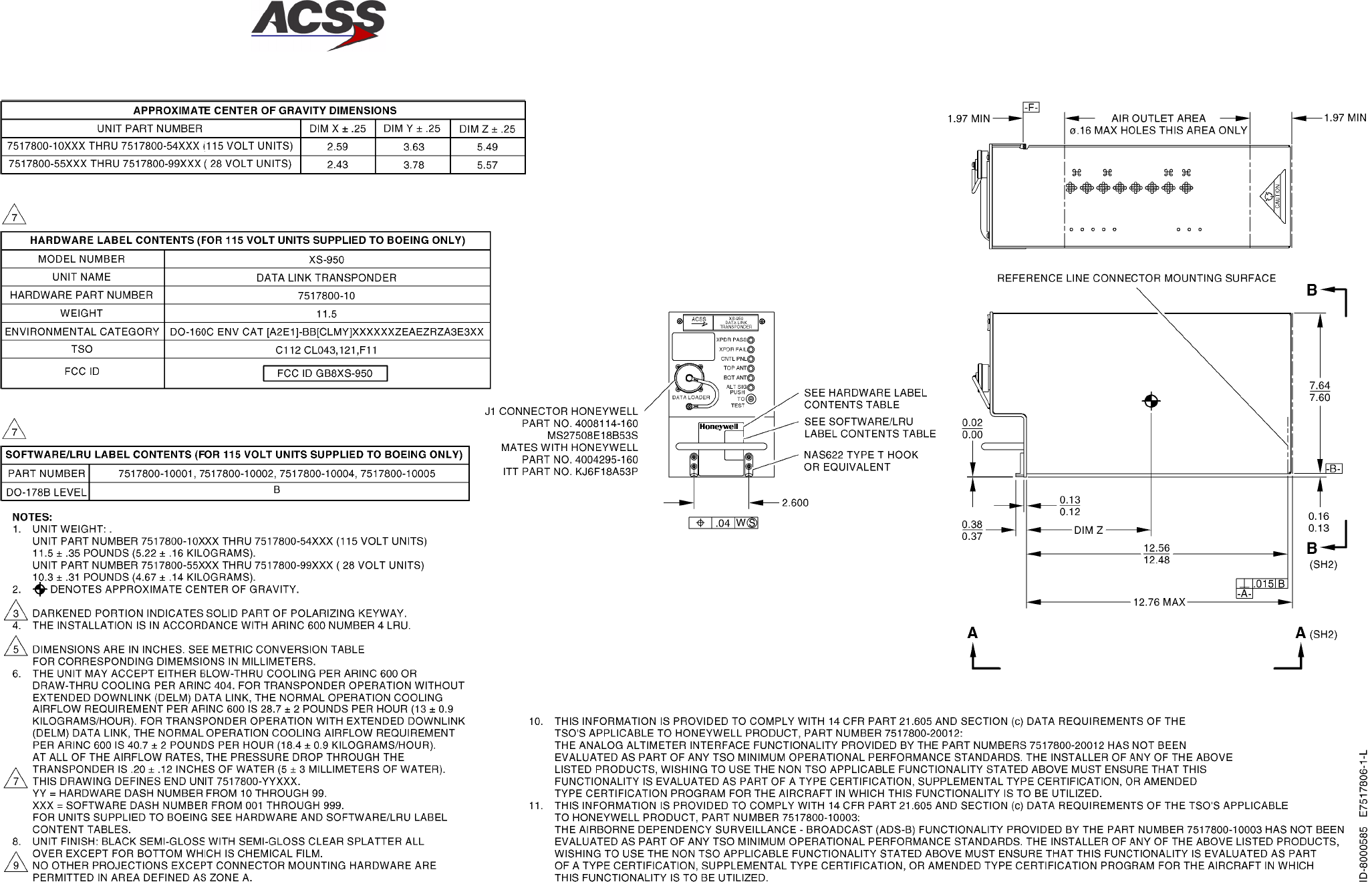
T2CAS / Part No. 9000000
SYSTEM DESCRIPTION AND INSTALLATION MANUAL
34-43-20 15 Feb 2003
Use or disclosure of information on this page is subject to the restrictions in the proprietary notice of this document.
2--29/(2--30 blank)
Figure 2--8 (Sheet 1). XS--950 Data Link Transponder Outline and Installation Diagram
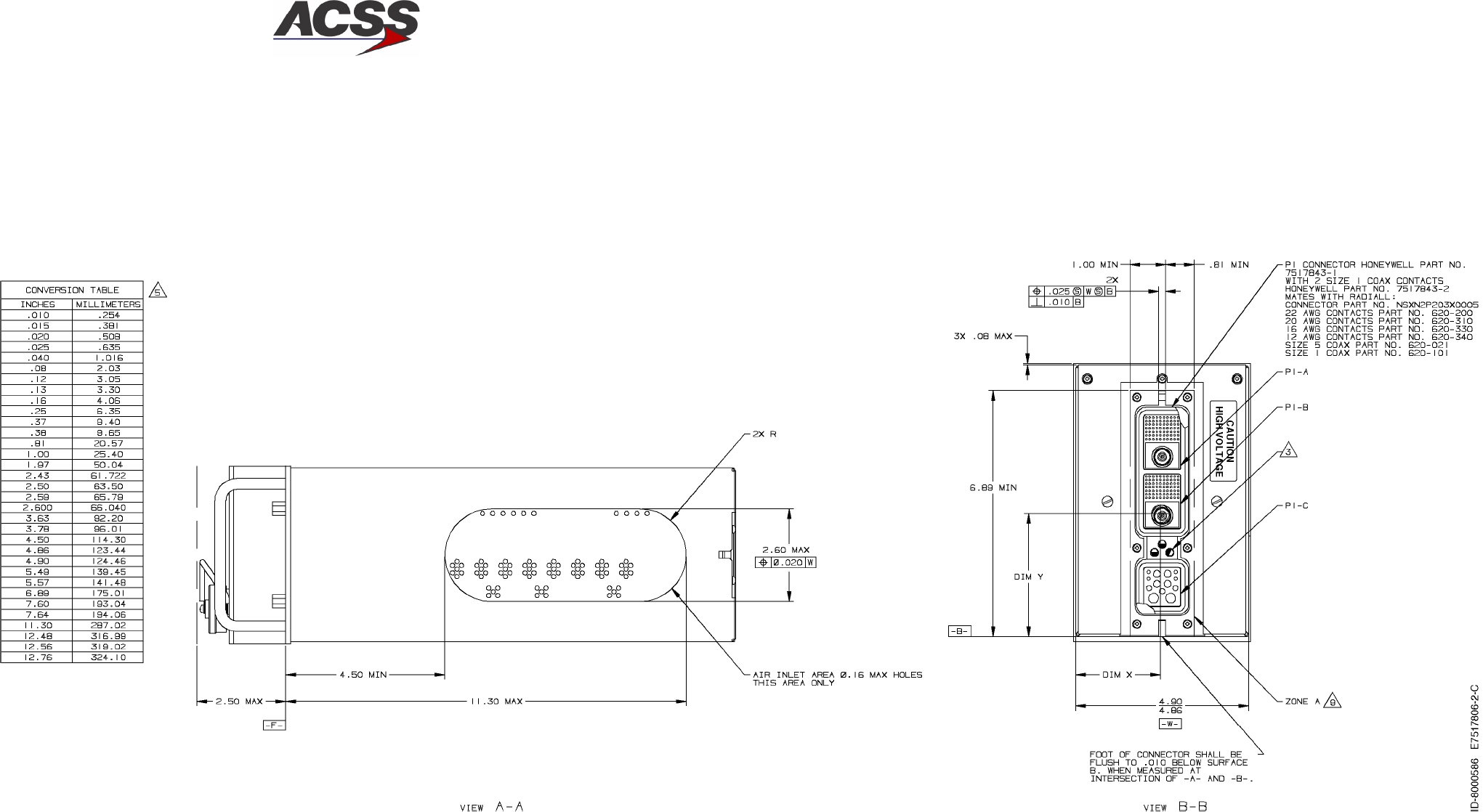
T2CAS / Part No. 9000000
SYSTEM DESCRIPTION AND INSTALLATION MANUAL
34-43-20 15 Feb 2003
Use or disclosure of information on this page is subject to the restrictions in the proprietary notice of this document.
2--31/(2--32 blank)
Figure 2--8 (Sheet 2). XS--950 Data Link Transponder Outline and Installation Diagram
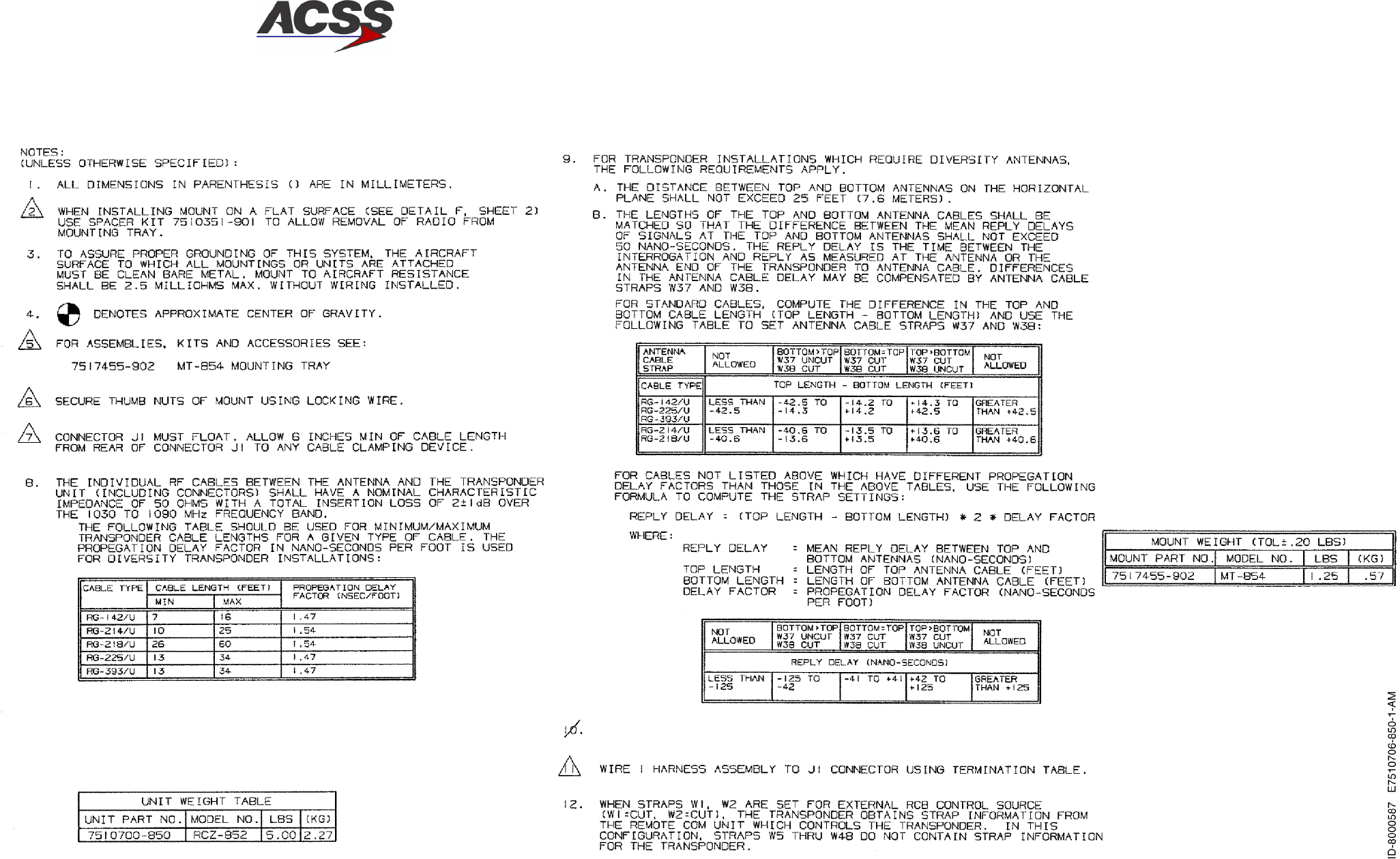
T2CAS / Part No. 9000000
SYSTEM DESCRIPTION AND INSTALLATION MANUAL
34-43-20 15 Feb 2003
Use or disclosure of information on this page is subject to the restrictions in the proprietary notice of this document.
2--33/(2--34 blank)
Figure 2--9 (Sheet 1). RCZ--852 Mode S Transponder Outline and Installation Diagram
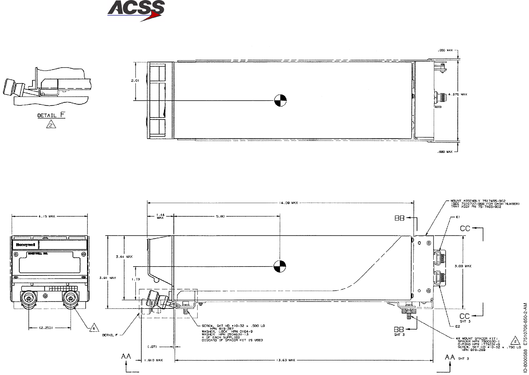
T2CAS / Part No. 9000000
SYSTEM DESCRIPTION AND INSTALLATION MANUAL
34-43-20 15 Feb 2003
Use or disclosure of information on this page is subject to the restrictions in the proprietary notice of this document.
2--35/(2--36 blank)
Figure 2--9 (Sheet 2). RCZ--852 Mode S Transponder Outline and Installation Diagram
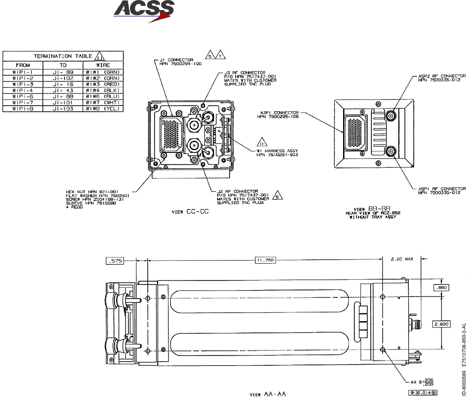
T2CAS / Part No. 9000000
SYSTEM DESCRIPTION AND INSTALLATION MANUAL
34-43-20 15 Feb 2003
Use or disclosure of information on this page is subject to the restrictions in the proprietary notice of this document.
2--37/(2--38 blank)
Figure 2--9 (Sheet 3). RCZ--852 Mode S Transponder Outline and Installation Diagram
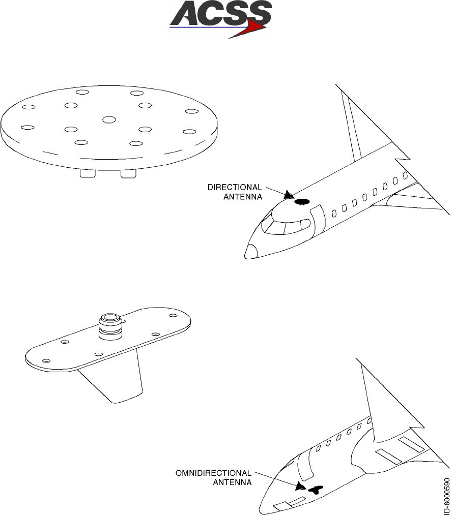
T2CAS / Part No. 9000000
SYSTEM DESCRIPTION AND INSTALLATION MANUAL
34-43-20 15 Feb 2003
Use or disclosure of information on this page is subject to the restrictions in the proprietary notice of this document.
2--39
Figure 2--10. TCAS Directional and Omnidirectional Antenna Locations
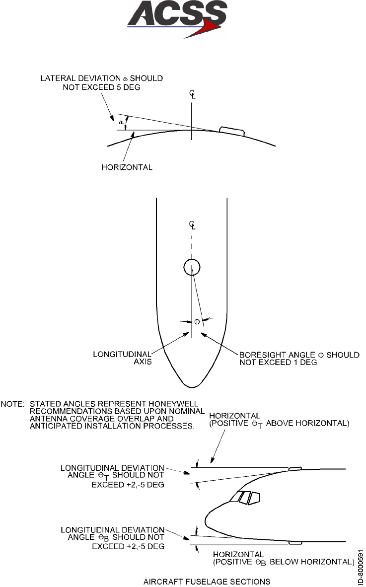
T2CAS / Part No. 9000000
SYSTEM DESCRIPTION AND INSTALLATION MANUAL
34-43-20
15 Feb 2003
Use or disclosure of information on this page is subject to the restrictions in the proprietary notice of this document.
2--40
Figure 2--11. Directional Antenna Angular Orientation
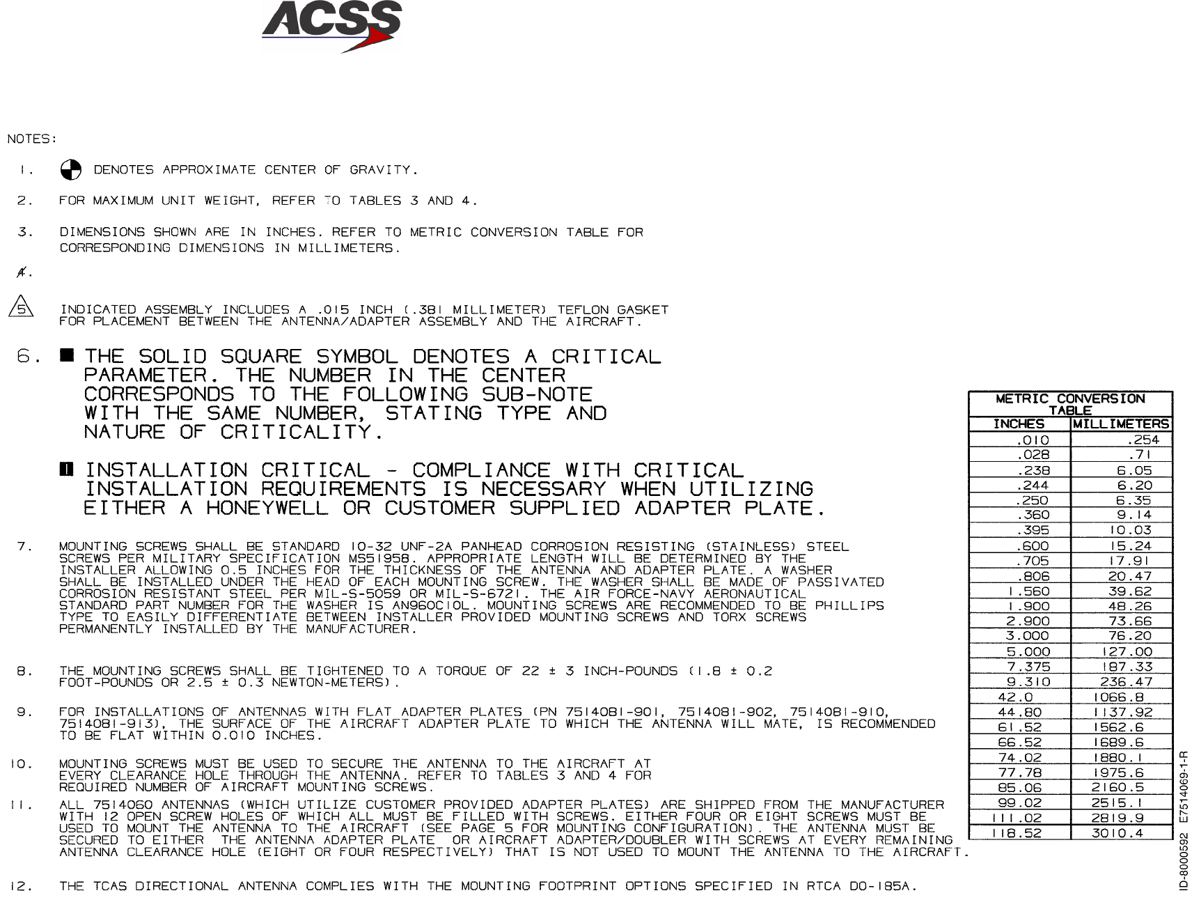
T2CAS / Part No. 9000000
SYSTEM DESCRIPTION AND INSTALLATION MANUAL
34-43-20 15 Feb 2003
Use or disclosure of information on this page is subject to the restrictions in the proprietary notice of this document.
2--41/(2--42 blank)
Figure 2--12 (Sheet 1). Directional Antenna Outline and Installation Diagram

T2CAS / Part No. 9000000
SYSTEM DESCRIPTION AND INSTALLATION MANUAL
34-43-20 15 Feb 2003
Use or disclosure of information on this page is subject to the restrictions in the proprietary notice of this document.
2--43/(2--44 blank)
Figure 2--12 (Sheet 2). Directional Antenna Outline and Installation Diagram
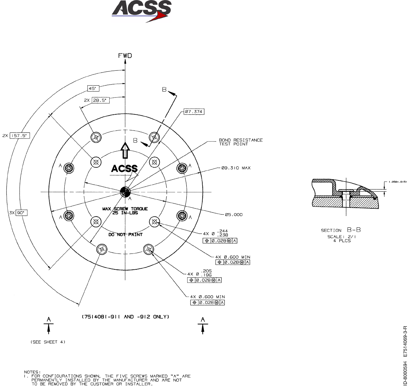
T2CAS / Part No. 9000000
SYSTEM DESCRIPTION AND INSTALLATION MANUAL
34-43-20 15 Feb 2003
Use or disclosure of information on this page is subject to the restrictions in the proprietary notice of this document.
2--45/(2--46 blank)
Figure 2--12 (Sheet 3). Directional Antenna Outline and Installation Diagram
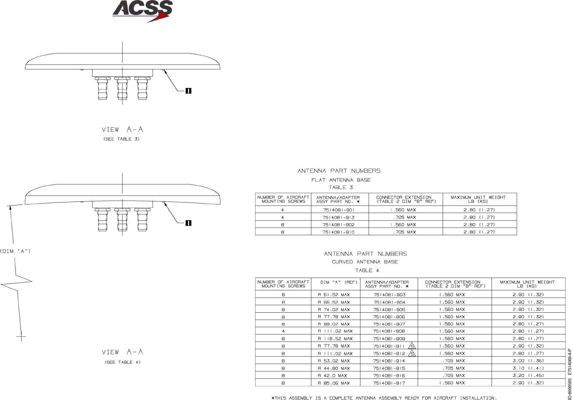
T2CAS / Part No. 9000000
SYSTEM DESCRIPTION AND INSTALLATION MANUAL
34-43-20 15 Feb 2003
Use or disclosure of information on this page is subject to the restrictions in the proprietary notice of this document.
2--47/(2--48 blank)
Figure 2--12 (Sheet 4). Directional Antenna Outline and Installation Diagram
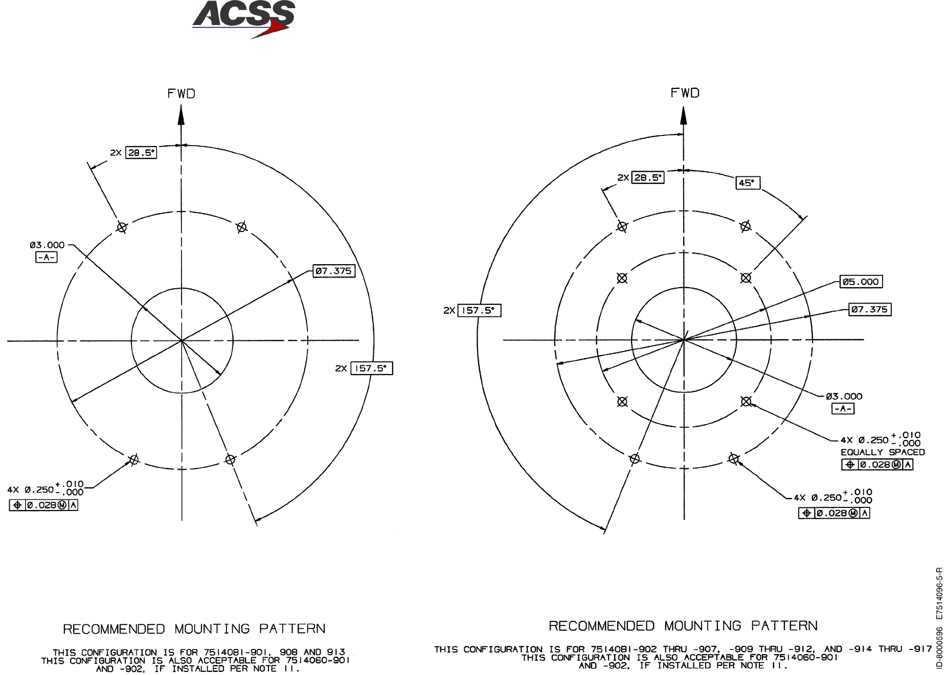
T2CAS / Part No. 9000000
SYSTEM DESCRIPTION AND INSTALLATION MANUAL
34-43-20 15 Feb 2003
Use or disclosure of information on this page is subject to the restrictions in the proprietary notice of this document.
2--49/(2--50 blank)
Figure 2--12 (Sheet 5). Directional Antenna Outline and Installation Diagram
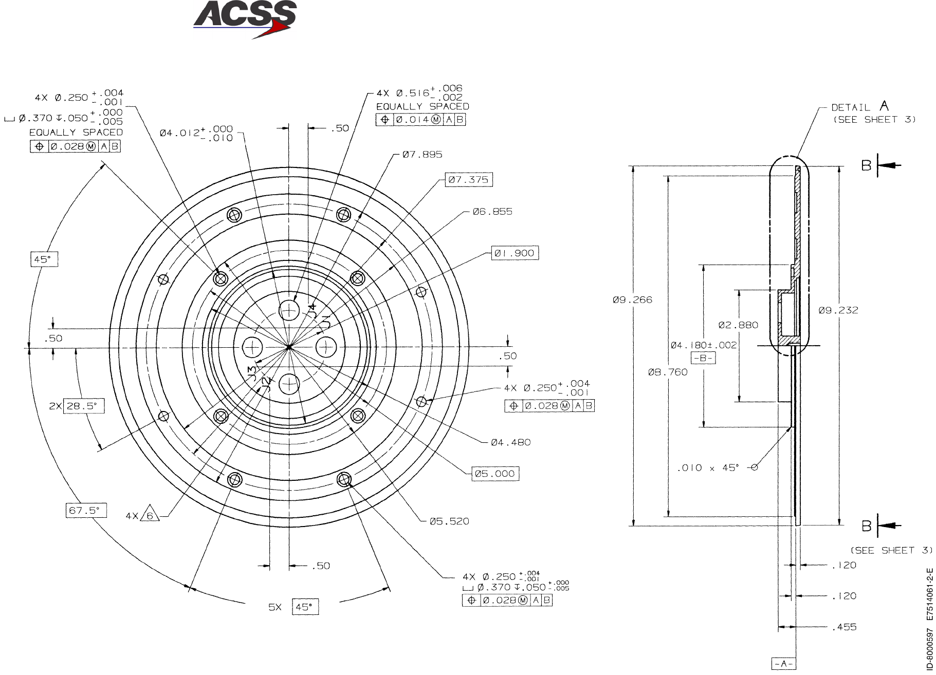
T2CAS / Part No. 9000000
SYSTEM DESCRIPTION AND INSTALLATION MANUAL
34-43-20 15 Feb 2003
Use or disclosure of information on this page is subject to the restrictions in the proprietary notice of this document.
2--51/(2--52 blank)
Figure 2--13 (Sheet 1). Directional Antenna Baseplate Outline and Installation Diagram