ADRF KOREA ADX-HPR-P DAS (Distributed Antenna System) User Manual
ADRF KOREA, Inc. DAS (Distributed Antenna System)
User Manual
AdvancedRFTechnologies,Inc. i
ADXDASHPRUserManual
Version0.1
3116WestVanowenSt.
Burbank,CA91505
Tel:818‐840‐8131
Fax:818‐840‐8138
www.adrftech.com

AdvancedRFTechnologies,Inc. ii
Informationinthisdocumentissubjecttochangewithoutnotice.
AdvancedRFTechnologies,Inc.1996‐2015.
Allrightsreserved.
Pleasesendcommentsto:
E‐Mail:info@adrftech.com
Phone: (818)840‐8131
(800)313‐9345
Fax: (818)840‐8138
Address:
AdvancedRFTechnologies,Inc.
Attention:TechnicalPublicationsDepartment
3116VanowenSt.
Burbank,CA91505
USA
www.adrftech.com
AdvancedRFTechnologies,Inc. iii
RevisionHistory
ChangeList
VersionChangelistContents
VersionAuthorDescriptionsDate
0.1CCKInitialRelease 05/13/15

AdvancedRFTechnologies,Inc. iv
TableofContents
1. Introduction......................................................................................................................................................14
1.1 Highlights...................................................................................................................................................14
1.2 HeadEndPartsList....................................................................................................................................15
1.2.1 ADX‐H‐NMS‐PKGPartsList.................................................................................................................15
1.2.2 ADX‐H‐BCUPartsList..........................................................................................................................16
1.2.3 ADX‐H‐RFUPartsList..........................................................................................................................16
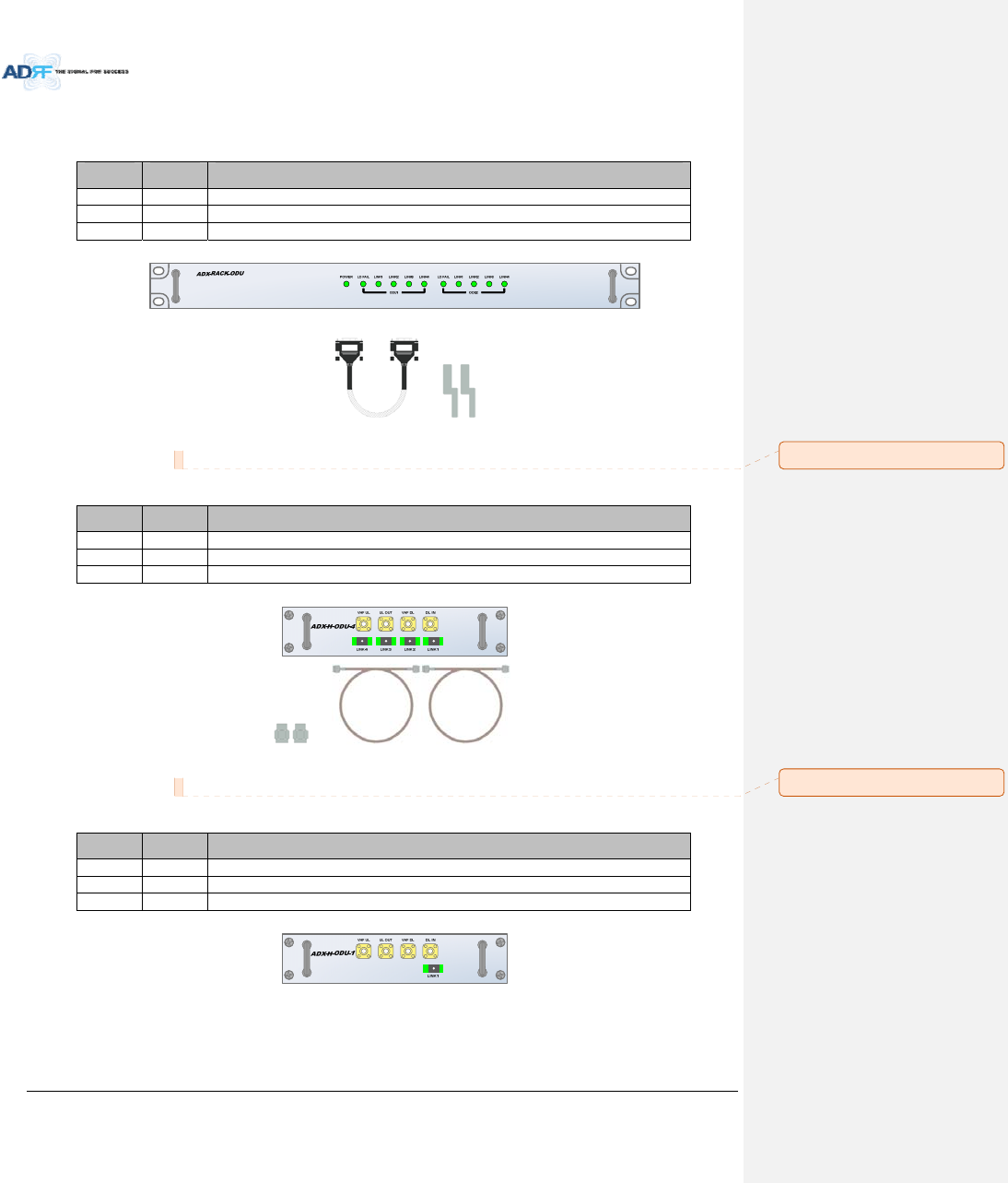
1.2.4 ADX‐RACK‐ODUPartsList...................................................................................................................17
1.2.5 ADX‐H‐ODU4‐XPartsList....................................................................................................................17
1.2.6 ADX‐H‐ODU1‐XPartsList....................................................................................................................17
1.3 HighPowerRemoteUnitPartsList............................................................................................................18
1.3.1 ADX‐R‐xxx46/44.8/43M(HPR)PartsList............................................................................................18
1.4 ADXDASQuickView..................................................................................................................................19
1.4.1 HEQuickView....................................................................................................................................19
1.4.3 RUQuickView....................................................................................................................................20
1.5 WarningsandHazards...............................................................................................................................21
2. ADX‐DASConfiguration.....................................................................................................................................24
2.1 ADXDASTopology.....................................................................................................................................24
2.2 Configuration.............................................................................................................................................25
2.2.1 Singlebandormulti‐bandconfiguration(1~8bands)........................................................................25
2.3 ADX‐DASScalability...................................................................................................................................26
3. ADXOverview...................................................................................................................................................
27
3.1 HeadEnd....................................................................................................................................................27
3.1.1 NMS(NetworkManagementSystem)................................................................................................28
3.1.1.1 LEDs..........................................................................................................................................28
3.1.1.2 EthernetPort............................................................................................................................29
3.1.1.3 Host/RemoteSwitch.................................................................................................................29
3.1.1.4 HEView/RUViewSwitch..........................................................................................................29
3.1.2 RFU(ADX‐H‐RFU‐x).............................................................................................................................30
3.1.2.1 LEDs..........................................................................................................................................30
3.1.2.2 RFPorts
.....................................................................................................................................31
3.1.2.3 CommunicationPort.................................................................................................................31
3.1.3 ChannelCombiner(ADX‐H‐CHC)........................................................................................................31
3.1.3.1 RFports.....................................................................................................................................31
3.1.4 OpticUnit(ADX‐RACK‐ODU,ADX‐H‐ODU4/ADX‐H‐ODU1).................................................................32
3.1.4.1 LEDs..........................................................................................................................................32
3.1.4.2 RFPorts.....................................................................................................................................32
3.1.4.3 OpticPorts................................................................................................................................33

AdvancedRFTechnologies,Inc. v
3.1.4.4 CommunicationPort.................................................................................................................33
3.1.5 PowerSupplyUnit(ADX‐H‐PSU).........................................................................................................33
3.1.5.1 LEDs..........................................................................................................................................33
3.1.5.2 ACInputOn/OffSwitch,ACInputPortandACInputSelectionSwitch....................................34
3.1.5.3 BatteryBackupPort,BatteryInstallPortandBatteryBackupSwitch......................................34
3.1.6 OptionalBandCombinerUnit(ADX‐H‐BCU‐x)...................................................................................35
3.1.6.1 LEDs..........................................................................................................................................35
3.1.6.2 RFPorts.....................................................................................................................................36
3.1.6.3 CommunicationPort.................................................................................................................36
3.2 HPR............................................................................................................................................................36
3.2.1 Port.....................................................................................................................................................36
3.2.1.1 RFPort......................................................................................................................................36
3.2.1.1.1 Antennaserverport(DINtype)..............................................................................................36
3.2.1.1.2 ExtensionFilterport(Ntype).................................................................................................37
3.2.1.2 Opticport..................................................................................................................................37
3.2.1.3 GUI,RS485port.......................................................................................................................38
3.2.2 LEDs....................................................................................................................................................38
3.2.3 ACOn/OffSwitch,ACPort..................................................................................................................39
3.2.4 DCOn/OffSwitch,DCPort.................................................................................................................40
4. CableConnection..............................................................................................................................................41
4.1 HeadEndConnectionDiagrams................................................................................................................41
4.1.1 Front/RearHeadEndConnectionViewwithOptionalBCUunit........................................................41
4.1.2 RearHeadEndConnectionViewwith(4)ADX‐RACK‐ODUunits.......................................................42
4.2 HighPowerRemoteUnitConnectionDiagrams........................................................................................43
5. Mountingmethod.............................................................................................................................................44
5.1 HeadEnd....................................................................................................................................................44
5.1.1 RackMount........................................................................................................................................44
5.1.2 WallMount.........................................................................................................................................45
5.2 HPR............................................................................................................................................................46
5.2.1 WallMount.........................................................................................................................................46
6. Installation........................................................................................................................................................46
6.1 Pre‐InstallationInspection.........................................................................................................................46
6.2 ADXDASInstallationProcedure................................................................................................................47
6.2.1 HEInstallationProcedure...................................................................................................................47
6.2.1.1 InstallingaADXDASHEinarack..............................................................................................47
6.2.1.2 WallmountingtheADXDASHE................................................................................................49
6.2.2 RUInstallationProcedure...................................................................................................................51
6.3 Grounding..................................................................................................................................................53
6.4 OpticPortCleaning....................................................................................................................................54

AdvancedRFTechnologies,Inc. vi
7. Commissioning..................................................................................................................................................55
7.1 Pre‐CommissioningCheck.........................................................................................................................55
7.1.1 Verifycableconnections....................................................................................................................55
7.1.2 ConnecttotheWeb‐GUI....................................................................................................................55
7.1.3 CheckNavigationTreeStatus.............................................................................................................56
7.1.4 SetLocationInfo,InstallerInfoandDate&Time...............................................................................56
7.1.5 VerifyNavigationTreeLinks...............................................................................................................56
7.1.6 BOMComparison&CheckBandConfiguration.................................................................................57
7.1.7 Lockcurrentnavigationtree..............................................................................................................57
7.2 Commissioning...........................................................................................................................................58
7.2.1 OpticCommissioning..........................................................................................................................58
7.2.1.1 Howtocompensatetheopticloss...........................................................................................58
7.2.2 HECommissioning..............................................................................................................................60
7.2.2.1 Compositepower.....................................................................................................................60
7.2.3 HPRCommissioning............................................................................................................................66
7.3 DASInstallVerification..............................................................................................................................67
7.3.1 SettingSNMP&RemoteIP.................................................................................................................67
7.3.2 VerificationthroughWebbasedGUI.................................................................................................67
7.3.3 ULnoisepowerdetection..................................................................................................................67
8. Web‐GUI...........................................................................................................................................................68
8.1 Web‐GUISetup..........................................................................................................................................68
8.1.1 DASsystem/PCConnectionUsingWeb‐GUI......................................................................................68
8.2 Administrator/UserMode.........................................................................................................................69
8.2.1 Common.............................................................................................................................................69
8.2.1.1 NavigationtreeLock/Unlock....................................................................................................69
8.2.1.2 NavigationTree........................................................................................................................69
8.2.1.3 PowerStatus.............................................................................................................................70
8.2.1.4 CommissioningStatus...............................................................................................................70
8.2.1.5 Information...............................................................................................................................70
8.2.2 StatusTab...........................................................................................................................................71
8.2.2.1 Status–NMS............................................................................................................................71
8.2.2.2 Status–BCU.............................................................................................................................74
8.2.2.3 Status–RFU..............................................................................................................................76
8.2.2.4 Status–ODU.............................................................................................................................78
8.2.2.5 Status–RUHub........................................................................................................................81
8.2.2.6 Status–Remotemodule..........................................................................................................82
8.2.3 ControlTab.........................................................................................................................................85
8.2.3.1 Control–NMS..........................................................................................................................85

AdvancedRFTechnologies,Inc. vii
8.2.3.2 Control–BCU...........................................................................................................................86
8.2.3.3 Control–RFU............................................................................................................................87
8.2.3.4 Control–ODU...........................................................................................................................91
8.2.3.5 Control–RHHub......................................................................................................................92
8.2.3.6 Control–RemoteModule(MasterorSlaveRU)......................................................................93
8.2.4 InstallTab...........................................................................................................................................96
8.2.4.1 Install–NMS.............................................................................................................................96
8.2.4.2 Install–BCU..............................................................................................................................99
8.2.4.3 Install–RFU............................................................................................................................100
8.2.4.4 Install–ODU...........................................................................................................................102
8.2.4.5 Install–HPRHub....................................................................................................................103
8.2.4.6 Install–RemoteModule(MasterorSlaveRU)......................................................................104
8.2.5 System..............................................................................................................................................106
8.2.5.1 System:Account.....................................................................................................................106
8.2.5.2 System:Logs...........................................................................................................................107
8.2.5.3 System:Update......................................................................................................................108
8.2.5.4 System:SystemInformation...................................................................................................109
8.2.5.5 System:Backup/Restore.........................................................................................................110
8.2.5.6 System:SNMP.........................................................................................................................112
8.2.5.7 System:CloseoutPackage......................................................................................................113
8.2.6 Help..................................................................................................................................................114
8.2.7 Logout...............................................................................................................................................114
8.3 GuestMode.............................................................................................................................................114
9. System‐WideSpecification(tobeconnectedtoHEviaOpticline)................................................................115
700LTE/CELL/SMR800 Specifications...........................................................................................................115
2. PCS/AWS/BRS Specifications....................................................................................................................116
3. SMR900 Specifications...............................................................................................................................117
4. WCS Specifications.....................................................................................................................................118
10. MechanicalDrawing.......................................................................................................................................119

AdvancedRFTechnologies,Inc. viii
Figures
Figure1‐1 ADXDASHEQuickView.....................................................................................................................19
Figure1‐2 ADXDASHPRQuickView...................................................................................................................20
Figure2‐1 ADXDASBlockDiagram(4BANDS)...................................오류!책갈피가정의되어있지않습니다.
Figure2‐2 ADXDASTopology..............................................................................................................................24
Figure2‐3 ADXDAS3bandsConfiguration..........................................................................................................25
Figure2‐4 ADXDAS4bandsConfiguration........................................오류!책갈피가정의되어있지않습니다.
Figure3‐1 HeadEndFrontView..........................................................................................................................27
Figure3‐2 ADX‐H‐NMSFrontView......................................................................................................................28
Figure3‐3 NMSLED.............................................................................................................................................28
Figure3‐4 EthernetPort......................................................................................................................................29
Figure3‐5 Host/RemoteSwitch...........................................................................................................................29
Figure3‐6 HEView/RUViewSwitch....................................................................................................................29
Figure3‐7 RFUFront&RearView.......................................................................................................................30
Figure3‐8 RFULED..............................................................................................................................................30
Figure3‐9 CommunicationPort(RFU).................................................................................................................31
Figure3‐10 ADX‐H‐CHCFront&RearView...........................................................................................................31
Figure3‐11 ADX‐RACK‐ODUFront&Rearview....................................................................................................32
Figure3‐12 ADX‐H‐ODU4andADX‐H‐ODU1InstalledinADX‐RACK‐ODU............................................................32
Figure3‐13 ADX‐RACK‐ODULED............................................................................................................................32
Figure3‐14 ODURFPorts......................................................................................................................................32
Figure3‐15 ODUOpticPorts.................................................................................................................................33
Figure3‐16 CommunicationPort(ODU)................................................................................................................33
Figure3‐17 ADX‐H‐PSUFront&RearView...........................................................................................................33
Figure3‐18 HEPSULED.........................................................................................................................................34
Figure3‐19 HEPSUACInputOn/OffSwitch,ACInputPortandACInputSelectionSwitch.................................34
Figure3‐20 BatteryBackupPort,BatteryInstallPortandBatteryBackupSwitch................................................34
Figure3‐21 ADX‐H‐BCUFront&RearView...........................................................................................................35
Figure3‐22 BCULED..............................................................................................................................................35
Figure3‐23 CommunicationPort(BCU)................................................................................................................36
Figure3‐24 ADX‐HPRSingleenclosure(bottomview)..........................................................................................36
Figure3‐25 InnerOpticportconnection...............................................................................................................37
Figure3‐26 Opticconnection................................................................................................................................38
Figure3‐27 ADX‐HPR3bandsGUIconnection(Singleenclosure).........................................................................38
Figure3‐28 ADX‐HPR4bandsGUI,RS485connection(2enclosures)오류!책갈피가정의되어있지않습니다.
Figure3‐29 HPRLED..............................................................................................................................................39
Figure3‐30 HPRACPort........................................................................................................................................39
Figure3‐31 HPRACSwitch....................................................................................................................................39
Figure4‐1 HECableconnection(1ADX‐RACK‐ODU+1BCU)..............................................................................42
Figure4‐2 HECableconnection(4ADX‐RACK‐ODUs)..........................................................................................43
Figure4‐3 ADX‐HPR3bandsconnection(Singleenclosure)................................................................................43
Figure4‐4 ADX‐HPR4bandsconnection(2enclosures)....................오류!책갈피가정의되어있지않습니다.
Figure5‐1 HERackMount(Front&Rearview)...................................................................................................44
Figure5‐2 HEWallMount(TopView).................................................................................................................45
Figure5‐3 HPRWallMount.................................................................................................................................46
Figure6‐1 ADXHE19”RackMountInstructions.................................................................................................48
Figure6‐2 ADXHEWallMountInstructions........................................................................................................49
Figure6‐3 WallMountInstructionsforADX‐HEadded1UUnit..........................................................................50
Figure6‐4 HPRWallMountInstructions.............................................................................................................52

AdvancedRFTechnologies,Inc. ix
Figure6‐5 GroundCableConnection(HErearside)............................................................................................53
Figure6‐6 GroundCableConnection(HPRdualside).........................................................................................53
Figure6‐7 OpticConnectorCleaning(left)andOpticPortCleaning(right)........................................................54
Figure6‐8 SC/APCOpticConnectorDustCap.....................................................................................................54
Figure7‐1 Loginwindow......................................................................................................................................55
Figure7‐2 NavigationtreeLock/Unlock..............................................................................................................56
Figure7‐3 Navigationtree...................................................................................................................................56
Figure7‐4 ODUInstallpage.................................................................................................................................58
Figure7‐5 measuredopticlossdisplay................................................................................................................58
Figure7‐6 BCUInstallWindow............................................................................................................................64
Figure7‐7 RFUInstallWindow............................................................................................................................65
Figure7‐8 RemoteModuleInstallWindow.........................................................................................................66
Figure8‐1 Loginscreen........................................................................................................................................68
Figure8‐2 NavigationtreeLock/Unlock..............................................................................................................69
Figure8‐3 Navigationtree...................................................................................................................................69
Figure8‐4 ADXDASGeneralInformation............................................................................................................70
Figure8‐5 Status‐NMS.......................................................................................................................................71
Figure8‐6 SystemSummary................................................................................................................................71
Figure8‐7 Systemscantime,HEview/RUview...................................................................................................72
Figure8‐8 HEalarmstatus...................................................................................................................................72
Figure8‐9 HECommissioningstatus...................................................................................................................73
Figure8‐10 Status–BCU.......................................................................................................................................74
Figure8‐11 Status–BCUBand..............................................................................................................................74
Figure8‐12 Status–BCUPower&Atten...............................................................................................................74
Figure8‐13 Status–BCUPowerRatio...................................................................................................................75
Figure8‐14 Status–BCUAlarm.............................................................................................................................75
Figure8‐15 Status–RFU........................................................................................................................................76
Figure8‐16 Status–RFUBand...............................................................................................................................76
Figure8‐17 Power&GainDisplay(Admin)...........................................................................................................76
Figure8‐18 Power&GainDisplay(User)..............................................................................................................77
Figure8‐19 Status‐ODU.......................................................................................................................................78
Figure8‐20 Summary(Status–ODU)....................................................................................................................78
Figure8‐21 RFStatus(Status–ODU)....................................................................................................................79
Figure8‐22 OpticStatus(Status–ODU)................................................................................................................79
Figure8‐23 OpticAttenuation(Status–ODU)......................................................................................................80
Figure8‐24 OpticPathStatus(Status–ODU).......................................................................................................80
Figure8‐25 Status‐HPRHub.................................................................................................................................81
Figure8‐26 RUAlarmStatus(Status‐HPRHub)...................................................................................................81
Figure8‐27 RUCommissioningStatus(Status‐HPRHub)....................................................................................81
Figure8‐28 Status–RemoteModule....................................................................................................................82
Figure8‐29 PCSBandInformation(Status–RemoteModule).............................................................................83
Figure8‐30 Power&Gain(Admin)........................................................................................................................83
Figure8‐31 Power&Gain(User)...........................................................................................................................83
Figure8‐32 OpticPower(Status–MasterHPRonly)............................................................................................84
Figure8‐33 Control‐NMS.....................................................................................................................................85
Figure8‐34 Heartbeat(Control–NMS).................................................................................................................85
Figure8‐35 HESystemReboot&FactorySetting(Control–NMS).......................................................................85
Figure8‐36 NMSSystemReboot&FactorySetting(Control–NMS)...................................................................85
Figure8‐37 Control–BCU.....................................................................................................................................86
Figure8‐38 Control–BCUManualATTControl....................................................................................................86
Figure8‐39 Control–BCUReboot/FactorySetting...............................................................................................87
Figure8‐40 Control–BCUAlarmSetting...............................................................................................................87
Figure8‐41 Control‐RFU......................................................................................................................................87

AdvancedRFTechnologies,Inc. x
Figure8‐42 GeneralSetting(Control–RFU)(Admin)............................................................................................88
Figure8‐43 GeneralSetting(Control–RFU)(User)...............................................................................................88
Figure8‐44 Reboot&FactorySetting(Control–RFU)..........................................................................................88
Figure8‐45 ULNoiseDetection(Control–RFU)...................................................................................................88
Figure8‐46 ULNoiseDetection‐PCSband...........................................................................................................89
Figure8‐47 ManualAttenuatorControlSetting(Control–RFU)..........................................................................89
Figure8‐48 AlarmThresholdSetting(Control–RFU)...........................................................................................90
Figure8‐49 Control–ODU.....................................................................................................................................91
Figure8‐50 OpticAttenuation–ODU....................................................................................................................91
Figure8‐51 Reboot&factorySetting(Control–ODU).........................................................................................92
Figure8‐52 Control–HPRHub..............................................................................................................................92
Figure8‐53 Reboot&FactorySetting(Control–HPRHub)..................................................................................92
Figure8‐54 Control–RemoteModule..................................................................................................................93
Figure8‐55 GeneralSetting(Control‐RU)...........................................................................................................93
Figure8‐56 Reboot&factorySetting(Control‐RU).............................................................................................94
Figure8‐57 OpticSetting(Control‐RU)................................................................................................................94
Figure8‐58 ManualAttenControl(Control‐RU)..................................................................................................94
Figure8‐59 AlarmSetting(Control‐RU)...............................................................................................................95
Figure8‐60 Install‐NMS.......................................................................................................................................96
Figure8‐61 HECommissioningStatus(Install–NMS)...........................................................................................96
Figure8‐62 SNMP(Install–NMS)..........................................................................................................................97
Figure8‐63 LocationSetting(Install–NMS).........................................................................................................97
Figure8‐64 ExternalModemBoxSetting(Install–NMS).....................................................................................97
Figure8‐65 Description(Install–NMS).................................................................................................................98
Figure8‐66 SNMPAgentFalseAlarmTest(Install–NMS)....................................................................................98
Figure8‐67 LocationInfo/InstallerInfo(Install–NMS).......................................................................................98
Figure8‐68 Date&TimeSetting(Install–NMS)...................................................................................................99
Figure8‐69 Install–BCU........................................................................................................................................99
Figure8‐70 Install–BCUCommissioning............................................................................................................100
Figure8‐71 Install–BCUDescription..................................................................................................................100
Figure8‐72 Install‐RFU.......................................................................................................................................101
Figure8‐73 RFUCommissioning(Install–RFU)...................................................................................................102
Figure8‐74 Description(Install–RFU)................................................................................................................102
Figure8‐75 Install–ODU.....................................................................................................................................102
Figure8‐76 Opticcontrol(Control–ODU)..........................................................................................................103
Figure8‐77 Description(Install–ODU)...............................................................................................................103
Figure8‐78 Install‐RUHub...................................................................................................................................104
Figure8‐79 RUCommissioningStatus(Install‐RUHub)......................................................................................104
Figure8‐80 Description(Install‐RUHub).............................................................................................................104
Figure8‐81 Install‐RemoteModule.....................................................................................................................105
Figure8‐82 RUOutputCommissioning(Install‐RU)............................................................................................105
Figure8‐83 Description(Install‐RemoteModule)...............................................................................................106
Figure8‐84 AccountManagement......................................................................................................................106
Figure8‐85 NewAccount....................................................................................................................................106
Figure8‐86 ChangePassword..............................................................................................................................107
Figure8‐87 EventLog..........................................................................................................................................107
Figure8‐88 UserLog............................................................................................................................................108
Figure8‐89 Systemupdate..................................................................................................................................108
Figure8‐90 MessageafterSystemupdateiscomplete.......................................................................................109
Figure8‐91 SystemInformation..........................................................................................................................109
Figure8‐92 SystemNotification..........................................................................................................................110
Figure8‐93 Billofmaterial..................................................................................................................................110
Figure8‐94 SettingBackup(Before)....................................................................................................................111

AdvancedRFTechnologies,Inc. xi
Figure8‐95 SettingBackup(After).......................................................................................................................111
Figure8‐96 SettingRestore.................................................................................................................................112
Figure8‐97 SNMPV1/V2.....................................................................................................................................112
Figure8‐98 SNMPV3...........................................................................................................................................113
Figure8‐99 System‐CloseoutPackage................................................................................................................113
Figure8‐100 System‐CloseoutPackageafterthefileupload...............................................................................113
Figure8‐101 Help..................................................................................................................................................114
Figure10‐1 HEDrawing.......................................................................................................................................119
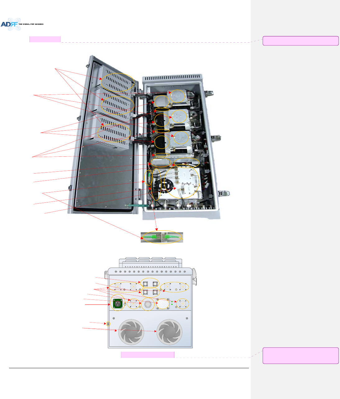
Figure10‐2 MasterHPRDrawing.........................................................................................................................120

AdvancedRFTechnologies,Inc. xii
Tables
Table1‐1 ADX‐H‐NMSPartsList.........................................................................................................................15
Table1‐2 ADX‐H‐BCUPartsList..........................................................................................................................16
Table1‐3 ADX‐H‐RFUPartsList..........................................................................................................................16
Table1‐4 ADX‐RACK‐ODUPartsList...................................................................................................................17
Table1‐5 ADX‐H‐ODU4PartsList.......................................................................................................................17
Table1‐6 ADX‐H‐ODU1PartsList.......................................................................................................................17
Table1‐7 MainHPRPartsList.............................................................................................................................18
Table1‐8 ExtendedHPRPartsList....................................................오류!책갈피가정의되어있지않습니다.
Table2‐1 ADX‐DASScalability............................................................................................................................26
Table3‐1 NMSLEDSpecifications......................................................................................................................28
Table3‐2 RFULEDSpecifications.......................................................................................................................30
Table3‐3 ODULEDSpecifications......................................................................................................................32
Table3‐4 HEPSULEDSpecifications..................................................................................................................34
Table3‐5 BCULEDSpecifications.......................................................................................................................35
Table3‐6 MasterHPRLEDSpecifications...........................................................................................................39
Table7‐1 Opticlosscompensationtable...........................................................................................................59
Table7‐2 Back‐offvalueforeachtechnologyduetotrafficbreathing..............................................................60
Table7‐3 Inputsignalconditions@HERFUdownlinkinput..............................................................................61
Table7‐4 HEmaximumdownlinkinputlevelwithout10dBattenuator............................................................61
Table7‐5 HEdownlinkinputsignalconditionsafteradding10dBattenuatortoHEdownlinkinputport........61
Table7‐6 HEmaximumdownlinkinputlevelafteradding10dBattenuatortoHEdownlinkinputport..........62
Table7‐7 Inputsignalconditions@HEBCUdownlinkinput..............................................................................62
Table7‐8 HEmaximumdownlinkinputlevel.....................................................................................................62
Table7‐9 Targetedmaximuminputpower........................................................................................................62
Table7‐10 MaximumOutputPowerpercarrier..................................................................................................63
Table8‐1 AccountInformationforLogin...........................................................................................................68
Table8‐2 Navigationtree...................................................................................................................................69
Table8‐3 PowerSupplyStatus...........................................................................................................................70
Table8‐4 CommissioningICON..........................................................................................................................70
Table8‐5 SystemSummaryDescription.............................................................................................................72
Table8‐6 DescriptionforHECommissioningstatus...........................................................................................73
Table8‐7 DescriptionforNMSalarm.................................................................................................................73
Table8‐8 RFUAlarmStatus................................................................................................................................77
Table8‐9 SummaryDescription.........................................................................................................................79
Table8‐10 Descriptionforopticpathstatus........................................................................................................80
Table8‐11 DescriptionforHPRCommissioningstatus........................................................................................82
Table8‐12 AlarmStatus(Status‐HPRHub).........................................................................................................82
Table8‐13 OperatingStatus(Status–RemoteModule)......................................................................................84
Table8‐14 DescriptionforGeneralSetting..........................................................................................................88
Table8‐15 DescriptionforMainGainControlSetting(Control–RFU)................................................................89
Table8‐16 DescriptionforAlarmThresholdSetting(Control–RFU)...................................................................90
Table8‐17 DescriptionforOpticAttenuation(Control–ODU)...........................................................................92
Table8‐18 DescriptionforGeneralSetting(Control‐RU)...................................................................................93
Table8‐19 DescriptionforOpticSetting(Control‐RU).......................................................................................94
Table8‐20 DescriptionforManualAttenControl(Control‐RU).........................................................................95
Table8‐21 DescriptionforHECommissioningStatus(Install–NMS)..................................................................96
Table8‐22 DescriptionforOpticcontrol(Control–ODU).................................................................................103
Table8‐23 DescriptionforHPRCommissioningstatus......................................................................................104

AdvancedRFTechnologies,Inc. xiii
TermsandAbbreviations
Thefollowingisalistofabbreviationsandtermsusedthroughoutthisdocument.
Abbreviation/TermDefinition
AGCAutomaticGainControl
ALCAutomaticLevelControl
AROMSADRF’RepeaterOperationandManagementSystem
BCUBandCombinerUnit
BTSBaseTransceiverStation
CDMACodeDivisionMultipleAccess
CHCChannelcombiner
CWContinuousWave(un‐modulatedsignal)
DASDistributedAntennaSystem
DLDownlink
DownlinkThepathcoveredfromtheBaseTransceiverStation(BTS)tothesubscribers’service
areaviatherepeater
HEHeadEnd
HPAHighPowerAmplifier
HWHardware
IFIntermediateFrequency
LNA LowNoiseAmplifier
LTELongTermEvolution
MSMobileStation
NMSNetworkManagementSystem
ODUOpticDistributionUnitwhichislocatedinADX‐RACK‐ODU.AnADX‐RACK‐ODUhastwo
ODUs.
OEUOpticExpansionUnit
PLLPhasedLockedLoop
PSUPowerSupplyUnit
RFRadioFrequency
RFURFChannelUnit
RURemoteUnitwhichiscomposedofmasterHPRandmultipleslavesRU
HPR HighPowerRU
RemoteModulegenerictermformasterHPRandMasterRU,slaveRU
SWSoftware
ULUplink
UplinkThepathcoveredfromthesubscribers’serviceareatotheBaseTransceiverStation(BTS)
viatherepeater
VSWRVoltageStandingWaveRatio

AdvancedRFTechnologies,Inc. 14
1. INTRODUCTION
Upto(8)frequencybandsinonebody:CurrentlytheADXsupports700MHz(LowerA,LowerB,LowerC,
andUpperC),700MHzPublicSafety&UpperDsupport,Cellular,PCS,SMR800/SMR900,AWS,WCSand
BRS‐TDLTEbands.
ADX‐HPR‐7F43,ADX‐HPR‐C43,ADX‐HPR‐W,ADX‐HPR‐P46,ADX‐HPR‐A46,ADX‐HPR‐BT46
1.1 Highlights
ModularStructure(HE)
‐ Supportsmultibandsservice(700MHz,700MHzPS,Cell,PCS,AWS,SMR800/SMR900,WCS,BRS‐
TDLTE,etc.)inonebody
‐ Supportsupto8RFunits
Supportsoptionalcombining/balancingofmultiplecarriers’signalsviaBCU(BandCombinerUnit)
Supportsuptoaofmaximumof8HighPowerRemoteUnits
Upto6BandinHPRenclosure
46/44.8/43dBmofdownlinkcompositeoutputpower
Requiresonlysinglestrandoffiberperremoteunit
Operateswithupto5dBoopticalloss(withADX‐H‐ODU4,singlemode),upto10dBoopticallosspossible(with
ADX‐H‐ODU1,singlemode)
SupportsSNMPv1,v2,v3(get,set&traps)
Web‐basedGUIInterface;No3rdpartyGUIsoftwarerequired
Web‐GUIconnectivityviaDHCPinhostmode
VersatilityandUsability:ADXgivestotalcontroltotheuser.Controlparameterssuchasgain,outputpower,
andalarmthresholdcanbechangedusingWeb‐GUIinterfaceallowingtheusertofinetunethesystemtothe
givenRFenvironment.
Uplinknoisemeasurementroutine
SupportRUViewmode,refertosection3.1.1.4
IncrementalAutomaticShutdown/ResumeTime:ADXgraduallyincreasesthetimespanbetweenautomatic
shutdownandresumeperiodbeforeitpermanentlyshutsitselfdown
SupportALCfunctiontopreventADXDASfrominputoverloadoroutputoverpower
메모 [C1]: 표기방법검토
W43‐>W44.8‐>W 로수정
메모 [C2]: 수정
메모 [H3]: 8‐>6 로수정
AdvancedRFTechnologies,Inc. 15
1.2 HeadEndPartsList
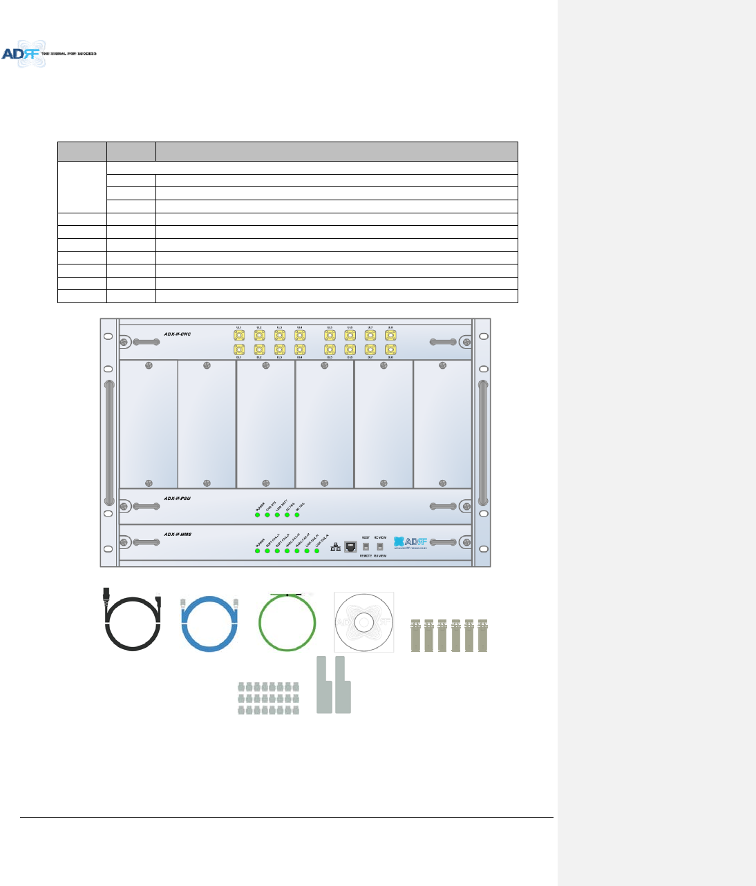
1.2.1 ADX‐H‐NMS‐PKGPartsList
Table1‐1ADX‐H‐NMSPartsList
LabelQuantityDescription
A
ADX‐H‐NMS‐PKG(NetworkManagementSystemPackage)
1ADX‐H‐NMS
1ADX‐H‐PSU(ACtoDCSupply)
1ADX‐H‐CHC(HeadEndChannelCombiner)
B1ACPowerCord
C1RJ‐45CrossoverCable
D1GroundCable
E1DocumentationCD(UserManual,QuickStartGuideandTroubleshootingGuide)
F1WallAnchorBoltSet
G28SMAterminators
H1L‐mountingBrace
A.
B. C. D. E. F.
G. H.
AdvancedRFTechnologies,Inc. 16
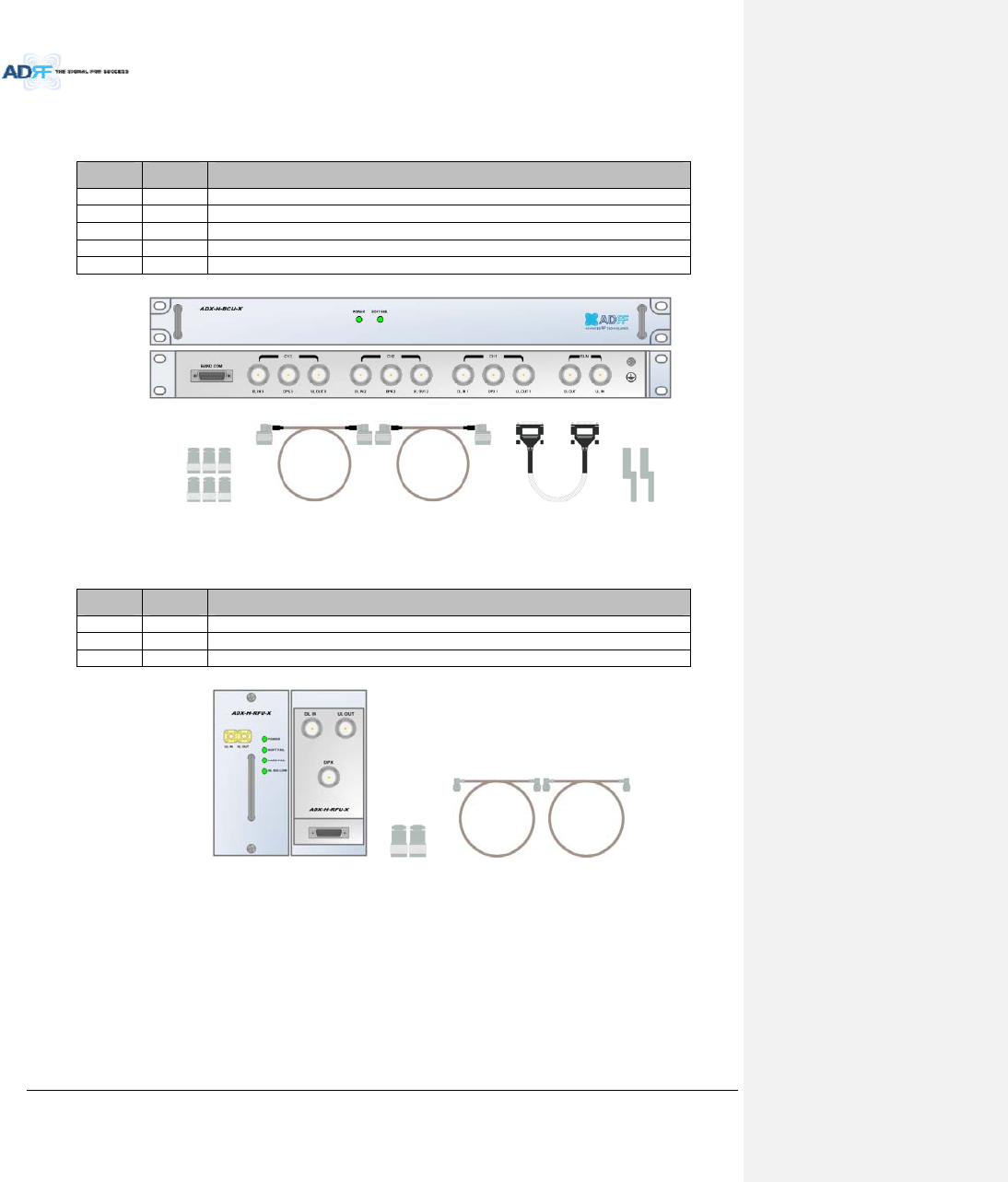
1.2.2 ADX‐H‐BCUPartsList
Table1‐2ADX‐H‐BCUPartsList
LabelQuantityDescription
A1ADX‐H‐BCU(BandCombinerUnit)
B6N‐Typeterminators
C2NMtoNMRFJumperCables(3ft)
D1Data/PowerCable
E2Chassismountingbrace
A.
B. C. D. E.
1.2.3 ADX‐H‐RFUPartsList
Table1‐3ADX‐H‐RFUPartsList
LabelQuantityDescription
A1ADX‐H‐RFU(RFUnit)
B2N‐TypeTerminators
C2SMAMaleRFJumperCables
A. B. C.
AdvancedRFTechnologies,Inc. 17
1.2.4 ADX‐RACK‐ODUPartsList
Table1‐4ADX‐RACK‐ODUPartsList
LabelQuantityDescription
A1ADX‐RACK‐ODU
B1Data/PowerCable
C1ChassisMountingBrace
A.
B. C.
1.2.5 ADX‐H‐ODU4‐XPartsList
Table1‐5ADX‐H‐ODU4PartsList
LabelQuantityDescription
A1ADX‐H‐ODU4(4‐portOpticalUnit)
B2SMA‐MTerminators
C2SMA‐MtoSMA‐MRFJumperCable(3ft)
A.
B. C.
1.2.6 ADX‐H‐ODU1‐XPartsList
Table1‐6ADX‐H‐ODU1PartsList
LabelQuantityDescription
A1ADX‐H‐ODU1(1‐portOpticalUnit)
B2SMA‐MTerminators
C2SMA‐MtoSMA‐MRFJumperCable(3ft)
A.
메모 [H4]: ‐X추가
메모 [H5]: ‐X추가
AdvancedRFTechnologies,Inc. 18
B. C.
1.3 HighPowerRemoteUnitPartsList
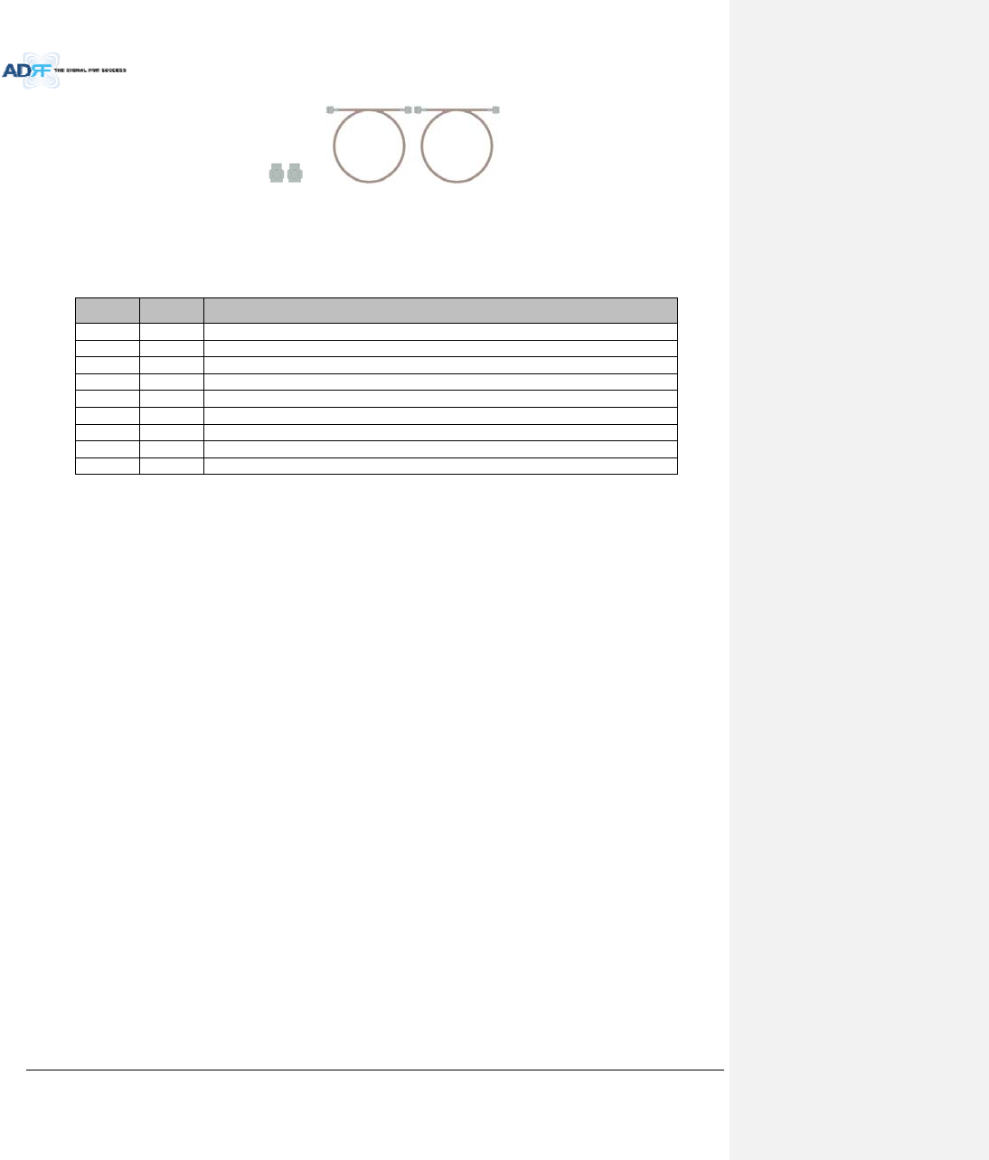
1.3.1 ADX‐R‐xxx46/44.8/43M(HPR)PartsList
Table1‐7HPRPartsList
LabelQuantityDescription
A1ADX‐R‐xxx46/44.8/43M(MainHPR)
B4Ntype‐Mterminators
C1USBCable
D1ACcable
E1Groundcable
F4AnchorBolt
G1ManualCD
H1Installguide
I1Wallmounttemplate
AdvancedRFTechnologies,Inc. 19
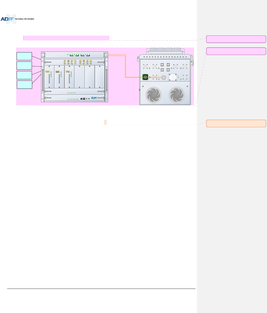
1.4 ADXDASQuickView
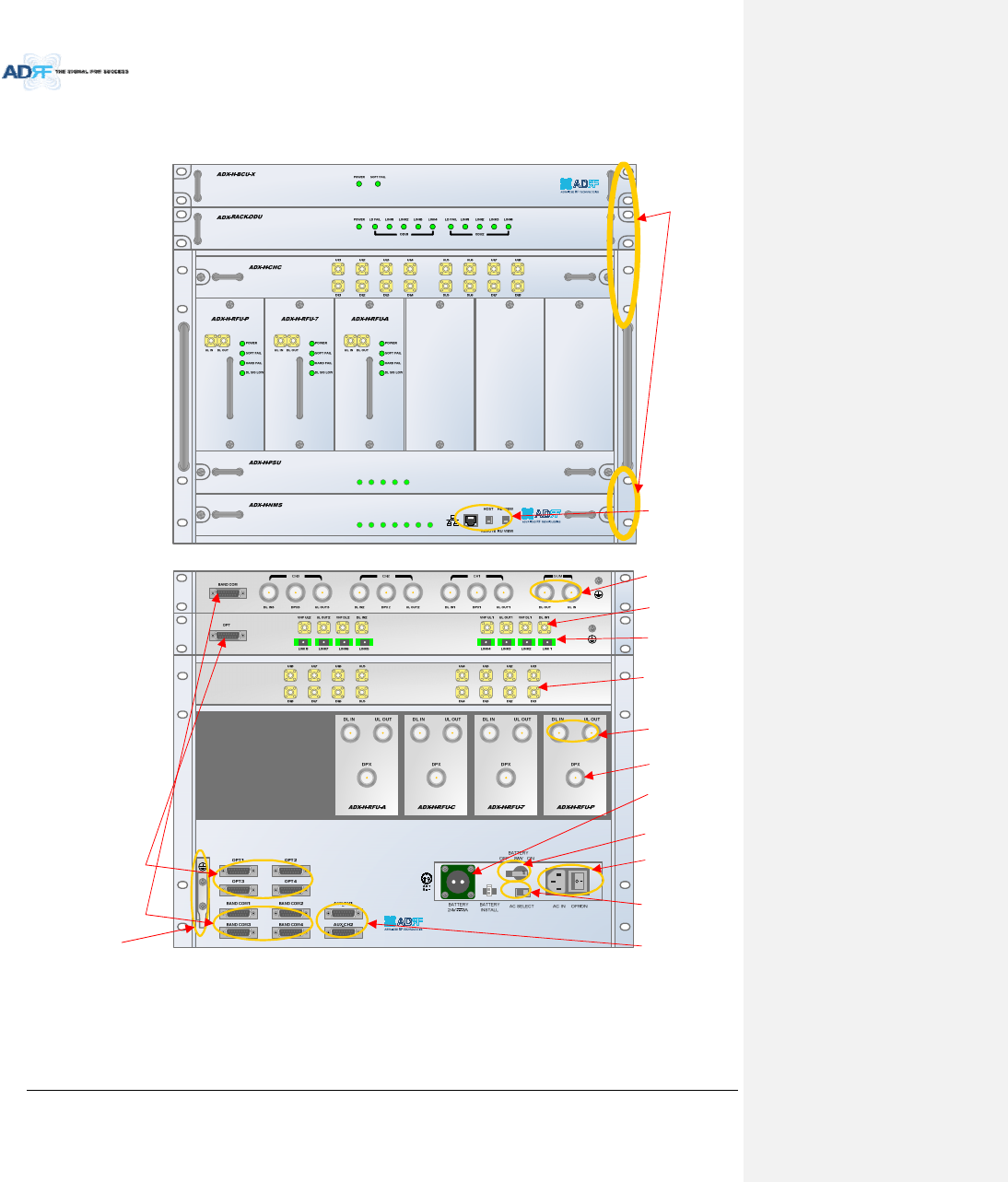
1.4.1 HEQuickView
1.4.2
POWER
SOFT FAIL-H
SOFT FAIL-R
HARD FAIL-H
HARD FAIL-R
LINK FAIL-H
LINK FAIL-R
POWER
CHG STS
LOW BATT
AC FAIL
DC FAIL
19” rackmount
Holes
Host/RemoteSwitch,
HEview/RUviewSwitch
&RJ‐45port
OpticPorts
BatteryBackup
Port
RFUDuplexPort
ACInput&
On/OffSwitch
BCUInterfacePorts
BandCombinerUnit
(BCU)
OpticUnit(ODU)
ChannelCombiner
(CHC)
RFChannelUnit
(RFU)
PowerSupplyUnit
(PSU)
NMSUnit
BatteryBackup
On/OffSwitch
ACInputVoltage
SelectionSwitch
(110V/220V)
RFUSimplex
Port
ODUInterfacePorts
AUXCHInterface
Ports
RFPortsconnectedto
ODU
RFPorts
connectedtoCHC
BCUSumPort
Figure1‐1ADXDASHEQuickView
Groundterminal
AdvancedRFTechnologies,Inc. 20
1.4.3 RUQuickView
BAN D 1 SER VER BAN D2 SER VER
AC IN 110V
A
B
C
A = AC_L
B = AC_N
C = F. G
OPTIC
GUI
EX_F1_IN
AB
EX_F 1_ O U T BAN D 3 SER VER BAN D4 SER VER
CPL
(-30dB)
CPL
(- 30dB )
CPL
(-30 dB )
CPL
( -30dB)
CPL
(- 30dB )
CPL
( -30dB)
BAN D6 SER VERBAN D5 SER VER
PO WER
RUN
EX_F2_O U TEX _F 2_IN
Serverantennaport
AC(DC)port
Opticport
Filterextensionport_2
LocalGUIport
Fanunit
Filterextensionport_1
Groundterminal
Figure1‐2ADXDASHPRQuickView
Controllerperband
RAU
Duplexer
HPA
ORU
RCU
Opticport
PSU
SplitterUnit
메모 [C6]: 사진수정필요
메모 [C7]: 수정해당도면그림의경우
김현기선임이추가해주시기바랍니다.
AdvancedRFTechnologies,Inc. 21
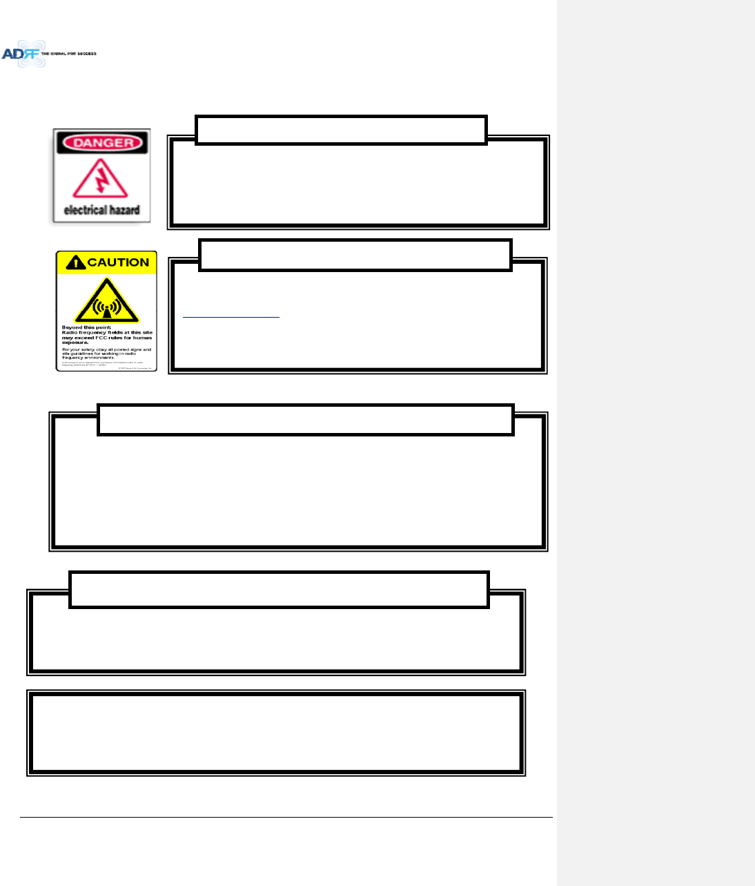
1.5 WarningsandHazards
OpeningortamperingtheADXDASwillvoidallwarranties.
WARRANTY
Actualseparationdistanceisdeterminedupongainofantennaused.Werecommendthatthemaximumantennagain
shouldnotbeexceed2dBifor698‐960MHzand3dBifor1710‐2690MHz.
RFexposurecomplianceshouldbeaddressedatthetimeoflicensing.
AntennasmustbeinstalledinaccordancewithFCCrule.Theheightoftheantennaaboveaverageterrain
(HAAT)ispermittedover1372m.Fordifferentgainantennasrefertotherelevantrules.
RFEXPOSURE&ANTENNAPLACEMENTGuidelines
WorkingwiththeADXDASwhileinoperation,mayexposethetechniciantoRF
electromagneticfieldsthatexceedFCCrulesforhumanexposure.VisittheFCCwebsiteat
www.fcc.gov/oet/rfsafetytolearnmoreabouttheeffectsofexposuretoRFelectromagnetic
fields.
WARNING!EXPOSURETORF
OpeningtheADXDAScouldresultinelectricshockandmaycause
severeinjury.
WARNING!ELECTRICSHOCK
LithiumBattery:CAUTION.RISKOFEXPLOSIONIFBATTERY ISREPLACEDBY INCORRECTTYPE.
DISPOSEOFUSEDBATTERIESACCORDINGTOINSTRUCTIONS.
AdvancedRFTechnologies,Inc. 22
WANRNING.THISisNOTaCONSUMERdevice.ItisdesignedforinstallationbyFCCLICENSEESand
QUALIFIEDINSTALLERS.YouMUSThaveanFCCLICENSEorexpressconsentofanFCCLicenseeto
operatethisdevice.Unauthorizedusemayresultinsignificantforfeiturepenalties,including
penaltiesinexcessof$100,000foreachcontinuingviolation.
FCCPart20
NOTE:ThisequipmenthasbeentestedandfoundtocomplywiththelimitsforaClassA
digitaldevice,pursuanttopart15oftheFCCRules.Theselimitsaredesignedtoprovide
reasonableprotectionagainstharmfulinterferencewhentheequipmentisoperatedina
commercialenvironment.Thisequipmentgenerates,uses,andcanradiateradiofrequency
energyand,ifnotinstalledandusedinaccordancewiththeinstructionmanual,maycause
harmfulinterferencetoradiocommunications.Operationofthisequipmentinaresidentialarea
islikelytocauseharmfulinterferenceinwhichcasetheuserwillberequiredtocorrectthe
interferenceattheirownexpense.
FCCPart15ClassA
EthernetInstructions:Thisequipmentisforindooruseonly.Allcablingshouldbelimitedto
insidethebuilding.
메모 [H8]: 추가15/5/18
메모 [H9]: 추가15/5/18
AdvancedRFTechnologies,Inc. 23
Useofunauthorizedantennas,cables,and/orcouplingdevicesnotconformingwith
ERP/EIRPand/orindoor‐onlyrestrictionsisprohibited.
Donotremovetheprotectivecoversonthefiberopticconnectorsuntilaconnectionisreadytobe
made.Donotleaveconnectorsuncoveredwhennotconnected.
Thetipofthefiberopticconnectorsshouldnotcomeintocontactwithanyobjectordust.
Refertothecleaningprocedureforinformationonthecleaningofthefibertip.
CareofFiberOpticConnectors
FiberopticportsoftheADXDASemitinvisiblelaserradiationatthe1310,1550nmwavelength
window.
Toavoideyeinjuryneverlookdirectlyintotheopticalports,patchcordsoropticalcables.Do
notstareintobeamorviewdirectlywithopticalinstruments.Alwaysassumeopticaloutputison.
Onlytechniciansfamiliarwithfiberopticsafetypracticesandproceduresshouldperformoptical
fiberconnectionsanddisconnectionsoftheADXDASandtheassociatedcables.
TheADXDAScomplieswith21CFR1040.10and1040.11exceptfordeviationspursuanttolaser
noticeNo.50(July26.2001)@IEC60825‐1,Amendment2(Jan.2001).
LaserSafety
AdvancedRFTechnologies,Inc. 24
2. ADX‐DASCONFIGURATION
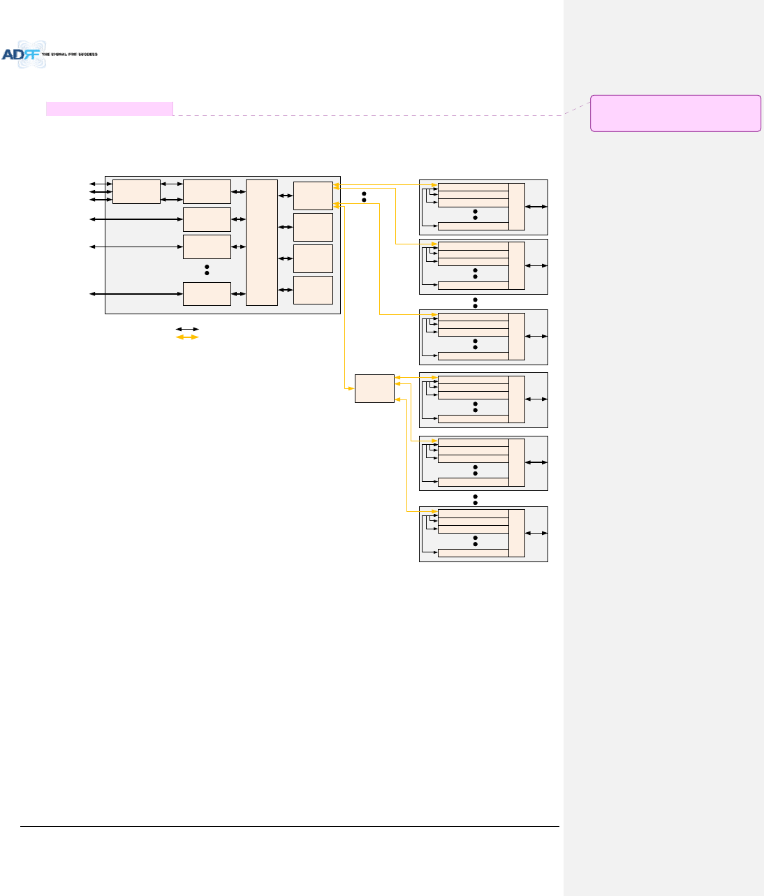
2.1 ADXDASTopology
HE(Head End Unit) RU(Remote Unit)
Optic
RF
PCS RFU
(RF Interface Unit
with BTS or BDA)
Cellular RFU
(RF Interface Unit
with BTS or BDA)
AWS RFU
(RF Interface Unit
with BTS or BDA)
BCU(optional)
(Band Combiner Unit
with BTS or BDA)
Service Carrier #1
Service Carrier #2
Service Carrier #3
Service Carrier #1
Service Carrier #2
CHC-H
(HE Channel
Combiner)
700M RFU
(RF Interface Unit
with BTS or BDA)
Service Carrier #2
OPT-H
(RF to Optical)
OPT-H
(RF to Optical)
OPT-H
(RF to Optical)
OPT-H
(RF to Optical)
PCS Master RU
Combiner
Cellular Slave RU
AWS Slave RU
700M Slave RU
PCS Master RU
Combiner
Cellular Slave RU
AWS Slave RU
700M Slave RU
PCS Master RU
Combiner
Cellular Slave RU
AWS Slave RU
700M Slave RU
PCS Master RU
Combiner
Cellular Slave RU
AWS Slave RU
700M Slave RU
OEU
(Optic Expansion
Unit)
PCS Master RU
Combiner
Cellular Slave RU
AWS Slave RU
700M Slave RU
PCS Master RU
Combiner
Cellular Slave RU
AWS Slave RU
700M Slave RU
Figure2‐1ADXDASTopology
메모 [C10]: BlockDiagram삭제(15.07.28)
_조찬기
AdvancedRFTechnologies,Inc. 25
2.2 Configuration
2.2.1 Singlebandormulti‐bandconfiguration(1~8bands)
BAN D 1 SE RVE R BAN D 2 SERVE R
AC IN 11 0V
A
B
C
A = AC _L
B = AC _ N
C = F.G
OPTIC
GUI
EX_F 1_IN
AB
EX_F 1_O U T BAN D 3 SE RVE R BAN D 4 SERVE R
CPL
(-30dB)
CPL
(-30 dB)
CPL
(-30 dB)
CPL
(-30dB)
CPL
(-30 dB)
CPL
(-30dB)
BAN D 6 SERVE RBAN D 5 SERVE R
PO WER
RUN
EX_F2_ OU TEX_F2_ IN
ADX-H-NMS
PO
WE
R
SO
F
T FAIL-H
SOFT FA
IL-R
HAR
D FAIL-H
HA
R
D FAIL-R
LINK FAIL-H
LINK FAIL-R
HOST HE VIEW
REMOTE RU VI EW
DL OUTUL IN
HARD FAIL
DL SIG LOW
S OFT FA I L
POWER
ADX- H-RFU- P
DL OUTUL IN
HARD FAIL
DL SIG LOW
S OFT FA I L
POWER
ADX-H-RFU- 7
DL OUTUL IN
HARD FAIL
DL SIG LOW
S O FT FA IL
POWER
ADX-H -RF U-C
ADX-H-CHC
UL1 UL2 UL3 UL4
DL1 DL2 DL3 DL4
UL5 UL6 UL7 UL8
DL5 DL6 DL7 DL8
ADX-H-PSU
POW
ER
C
HG STS
L
O
W B
A
TT
A
C F
AIL
DC F
AIL
LD FAI L LI NK 1 LI NK2 LI NK3 LI NK 4POWER
ADX -RACK-ODU
LD FA IL LI N K1 LIN K 2 LI N K3 LIN K4
ODU2ODU1
700LTE
PCS
CELL
BTS
Figure2‐2ADXDAS6bandsConfiguration
‐ HPRiscomposedofonlyMainHPRfor1~6bandsconfiguration
‐ Inthiscase,HPRhastwoORU.
메모 [C11]: 수정
메모 [C12]: 수정(CK)
메모 [H13]: 8‐>6으로수정함.
AdvancedRFTechnologies,Inc. 26
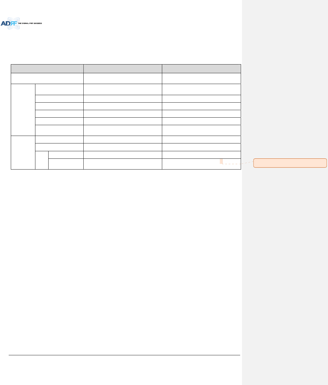
2.3 ADX‐DASScalability
Table2‐1ADX‐DASScalability
UnitScalabilityRemarks
Supportedband700M,Cellular,AWS,PCS,SMR800/900,
PS700,WCS,BRSTD‐LTE
HE
RFUUpto8upto6:cardtype
7
th
&8
th
RFU:19”racktype
NMS1
ChannelCombiner1
OpticUnitUpto4
BandCombinerUnitUpto4Tosupportmultiplecarriers
PowerSupplyUnit
(ACorDC)1Capableofsupplyingpowerto8RFUs,4
BCUs,4ODUracksandNMS.
RUorHPR
RUorHPRUpto60
OEUUpto4
PSU
(RU)
Adaptortype1perremotemodule
19”rackmount
(ACorDC)1Capableofsupplyingpowerto6Remote
Modules
메모 [H14]: 8‐>6 으로수정
AdvancedRFTechnologies,Inc. 27
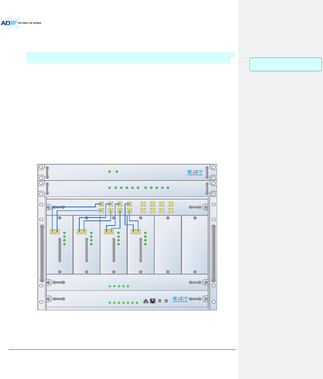
3. ADXOVERVIEW
3.1 HeadEnd
TheheadendunitmustalwaysbeconnectedtotheBaseStationusingadirectcabledconnection.This
systemhasnotbeenapprovedforusewithawirelessconnectionviaserverantennatothebasestation.
Headendcomponentsinclude:
ADX‐H‐NMS(NetworkManagementSystem)
ADX‐H‐CHC(HeadEndChannelCombiner)
ADX‐H‐PSU(HeadEndPowerSupply)
Upto[4]ADX‐H‐BCU(BandCombinerUnit)
Upto[8]ADX‐H‐RFU‐x(RFUnit)
Upto[4]ADX‐RACK‐ODU(OpticalUnit)
Specifications
‐ Size:19.0x14.6x12.2inches(482x370x311mm)
‐ Weight:83.7lbs(38.0Kg)@4RFU,CHC‐H,PSUandNMS
‐ PowerConsumption:52W@4RFU,1ADX‐H‐ODU4andNMS,28W@1RFU,1ADX‐H‐ODU4and
NMS
‐ PowerInput:110VACor‐48VDC(optional)
‐ SupportstheADRF‐BBUforexternalbatterybackupsolution
ADX- H-NM S
P
OWE
R
SO
FT FAIL-H
S
O
FT FAIL-R
H
ARD
FA
IL-H
HA
RD FAIL-R
LINK FAIL -H
LIN K
FA
IL-R
HOST HE VIEW
REMOTE RU VIEW
ADX- H-PSU
P
OWE
R
CHG S
TS
LOW
B
ATT
A
C FAIL
DC FAIL
DL OUTUL IN
HARD FAIL
DL SIG LOW
S O FT FA I L
POWER
ADX-H -RFU-P
DL OUTUL IN
HARD FAIL
DL SIG LOW
S O FT FA I L
POWER
ADX-H -RFU-7
DL OUTUL IN
HARD FAIL
DL SIG LOW
S O FT FA I L
POWER
ADX-H -RFU-C
DL OUTUL IN
HARD FAIL
DL SIG LOW
SOFT FAIL
POWER
ADX -H- RFU-A
ADX- H-CHC
UL1UL2UL3UL4
DL1DL2DL3DL4
UL5UL6UL7UL8
DL5DL6DL7DL8
LD FA I L5- 8 LI N K5 LI N K 6 LI N K7 LI N K8LD FA I L1- 4 LI N K1 LI N K 2 LI N K3 LI N K4POWER
ADX- H-RACK -ODU
SOFT FAILPOWER
ADX- H-BCU -P
Figure3‐1HeadEndFrontView
메모 [Y15]: 추가
15/05/18
AdvancedRFTechnologies,Inc. 28
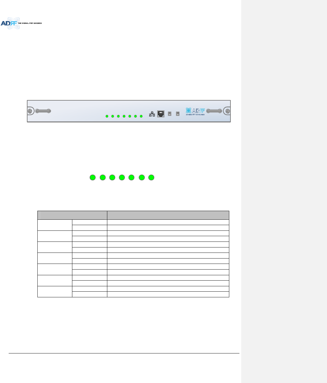
3.1.1 NMS(NetworkManagementSystem)
Functionsandfeatures
‐ SupportsSNMPv1,v2,andv3(get,set&trap)andweb‐basedGUIInterface.
‐ Monitorsalarmsandstatus
‐ Providescontrolinterfaceswithallsubordinatemodules
‐ ProvidesoverallDASstructureviatheautotreeupdatefunction
Spec
‐ Size:19.0x12.1x1.7inches
‐ Weight:5.5lbs
ADX -H- NMS
P
OWE
R
S
OFT FA
IL-H
S
OFT FA
IL-R
HA
RD FAIL-H
HA
RD FAIL-R
LIN
K FAIL-H
LIN
K FAIL-R
HOST HE VIEW
REMOTE RU VIEW
Figure3‐2ADX‐H‐NMSFrontView
3.1.1.1 LEDs
NMShasLEDsonthefrontpanelasshowninFigure3‐3.
P
OW
ER
SO
FT-FA
IL-H
SO
FT-FA
IL-R
H
AR
D-FAIL-H
H
AR
D-FAIL-R
LIN K
FAIL-H
LIN K
FAIL-R
Figure3‐3NMSLED
Table3‐1NMSLEDSpecifications
ADXDAS‐NMSSpecifications
PowerSolidGreenNMSpowerisON
OFF NMSpowerisOFF
SOFTFAIL‐HSolidYellowHESoftFailalarmexistsinthesystem
SolidGreenNoHESoftFailalarmsarepresentinthesystem
SOFTFAIL‐RSolidYellowRUSoftFailalarmexistsinthesystem
SolidGreenNoHPRSoftFailalarmsarepresentinthesystem
HARDFAIL‐HSolidRedHEHardFailalarmexistsinthesystem
SolidGreenNoHEHardFailalarmsarepresentinthesystem
HARDFAIL‐RSolidRedRUHardFailalarmexistsinthe system
SolidGreenNoHPRHardFailalarmsarepresentinthesystem
LINKFAIL‐HSolidYellowHELinkFailalarmexistsinthesystem
SolidGreenNoHELinkFailalarmsarepresentinthesystem
LINKFAIL‐RSolidYellowRULinkFailalarmexistsinthesystem
SolidGreenNoHPRLinkFailalarmsarepresentinthesystem
AdvancedRFTechnologies,Inc. 29
3.1.1.2 EthernetPort
TheEthernetportcanbeusedtocommunicatedirectlywiththeADXDASusingaRJ‐45crossovercableorcan
alsobeusedtoconnecttheADXDAStoanexternalmodembox.
HOST HE VIEW
REMOTE RU VIEW
Figure3‐4EthernetPort
3.1.1.3 Host/RemoteSwitch
TheHost/RemoteSwitchallowstheusertoswitchthedefaultRepeaterIP,SubnetMask,andGatewayofthe
repeatertoanalternativesetup.ThesesettingscanbeadjustedbyloggingintotheADXDASinHOSTmodeand
configuringthesettingsundertheModemBoxSettingsectionundertheInstallPageofNMS.
Oncethesettingsareset,flippingtheswitchtotheREMOTEpositionwillrebootNMSmodulewiththenew
alternatesettings.PleasenotethatwhentheNMSissettotheREMOTEposition,DHCPisdisabledandtheNMS
willnotautomaticallyassignanIPaddresstoanydevicethatconnectsdirectlytotheNMS.
HOST HE VIEW
REMOTE RU VIEW
Figure3‐5Host/RemoteSwitch
HostIP:192.168.63.1(FixedIP,unabletomodifythisIPaddress)
RemoteIP:192.168.63.5(DefaultIP,butcanbemodifiedinHostmode)
3.1.1.4 HEView/RUViewSwitch
TheHEView/RUViewSwitchallowstheusertodisabletheperiodicmonitoringperformedbytheNMS.Inthe
HEviewmode,theNMSmonitorsthestatusofallsubordinateunitsconnectedtoNMSbutwhenswitchedtoHPR
viewtheNMSdoesnotmonitorthesubordinateunits.HPRViewmodewillallowtheusertogotoaHPRand
monitor/controltheHE.IftheNMSissettotheHEViewmodeandtriestoconnecttoaHPRtomonitortheHE,
datacollisionsbetweentheNMSandHPRmaypreventtheuserfromproperlymonitoringorconfiguringtheHE
whenattheRU.
HOST HE VIEW
REMOTE RU VIEW
Figure3‐6HEView/RUViewSwitch
AdvancedRFTechnologies,Inc. 30
3.1.2 RFU(ADX‐H‐RFU‐x)
DL OUTUL IN
HARD FAIL
DL SIG LOW
S O FT FA I L
POWER
ADX -H- RFU-P
DL I N UL O UT
DPX
AD X -H- R F U-P
Figure3‐7RFUFront&RearView
Functionsandfeatures
‐ ProvideRFinterfacewithBTS
‐ EachRFUhasindependentgaincontrolandfiltering
‐ Modulartypeandhotswappable
‐ SupportsduplexportorsimplexTX&RXports
‐ EasilysupportadditionalfrequencybandsbyaddingasingleRFU
‐ Reducescomplexityandoverallequipmentsize
Specifications
‐ Size:12.8x6.2x2.8inches
‐ Weight:7.3lbs
3.1.2.1 LEDs
RFUhasLEDsonthefrontpanelasshowninFigure3‐8.
HARD FAIL
DL SIG LOW
S O FT FA I L
POWER
Figure3‐8RFULED
Table3‐2RFULEDSpecifications
ADXDAS‐ModuleSpecifications
PowerSolidGreenModulepowerisON.
OFF ModulepowerisOFF.
SoftFailSolidYellowSoftFailalarmexistsintheRFU.
SolidGreenNoSoftFailalarmsarepresentintheRFU.
HardFailSolidRedHardFailalarmexistsintheRFU.
SolidGreenNoHardFailalarmsarepresentintheRFU.
DLSIGLOWSolidYellowWhenDLinputsignallevelislowerthanthedefinedthreshold
level.(defaultthresholdvalue:‐5dBm)
SolidGreenWhenDLinputsignallevelisupperthanthedefinedthreshold
level.
AdvancedRFTechnologies,Inc. 31
3.1.2.2 RFPorts
3.1.2.2.1 DLIN/ULOUT&DPXports
DLIN/ULOUT&DPXPorts(refertoFigure3‐7)arelocatedatthebackofRFUandcanbeconnecteddirectlyto
theBTS.TheRFUcansupportincomingsignalstrengthfrom0to25dBm.
3.1.2.2.2 DLOUT/ULIN
DLOUT/ULINPorts(refertoFigure3‐7)arelocatedatthefrontoftheRFUandconnectdirectlytotheHE
ChannelCombiner(ADX‐H‐CHC).
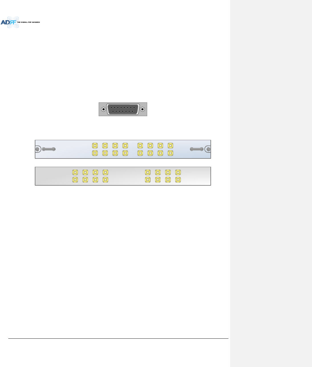
3.1.2.3 CommunicationPort
TheADX‐H‐NMSmonitorsandcontrolstheRFUviathisport.DCPowerisalsoprovidedtotheRFUviathisport.
Figure3‐9CommunicationPort(RFU)
3.1.3 ChannelCombiner(ADX‐H‐CHC)
ADX -H- CHC
UL1 UL2 UL3 UL4
DL1 DL2 DL3 DL4
UL5 UL6 UL7 UL8
DL5 DL6 DL7 DL8
UL5UL6UL7UL8
DL5DL6DL7DL8
UL1UL2UL3UL4
DL1DL2DL3DL4
Figure3‐10ADX‐H‐CHCFront&RearView
Functions&Features
‐ CombinesDLsignalsreceivedfromeachRFUandfeedsthecombinedsignalstotheADX‐RACK‐
ODU
‐ CombinesULsignalsreceivedfromeachHPRandfeedsthecombinedsignaltotheADX‐H‐RFU
‐ Supportsupto8RFUsand(4)ADX‐RACK‐ODU
Specifications
‐ Size:16.9x12.9x1.7inches
‐ Weight:11.0lbs
3.1.3.1 RFports
3.1.3.1.1 RFportsatthefrontpanel(DL1toDL8,UL1toUL8)
DL1(toDL8)&UL1(toUL8)RFportsareconnectedtoDLOUT/ULINPortsatthefrontpanelofRFU.
ReceivethedownlinksignalfromeachRFU
SplittheuplinksignalreceivedfromODUtoeachRFU
3.1.3.1.2 RFportsatthebackpanel(DL1toDL8,UL1toUL8)
DL1(toDL8)&UL1(toUL8)RFportsareconnectedtoDLIN/ULOUTPortsatthebackpanelofODU.
TransferthecombineddownlinksignalstoODU
ReceivetheuplinksignalfromODU
AdvancedRFTechnologies,Inc. 32
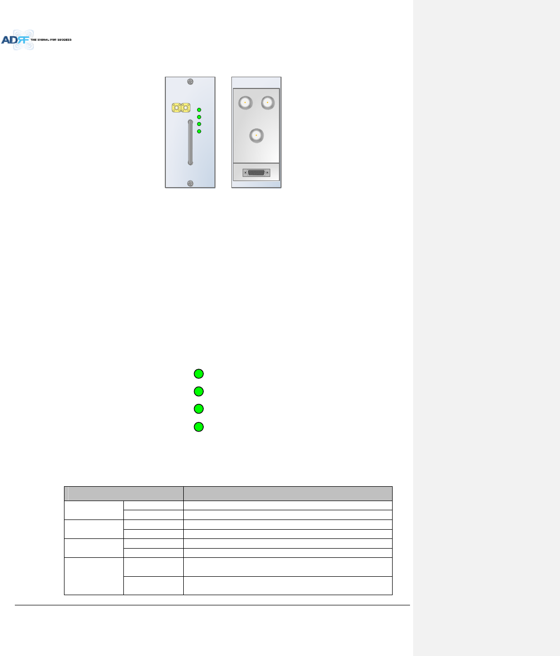
3.1.4 OpticUnit(ADX‐RACK‐ODU,ADX‐H‐ODU4/ADX‐H‐ODU1)
Figure3‐11ADX‐RACK‐ODUFront&Rearview
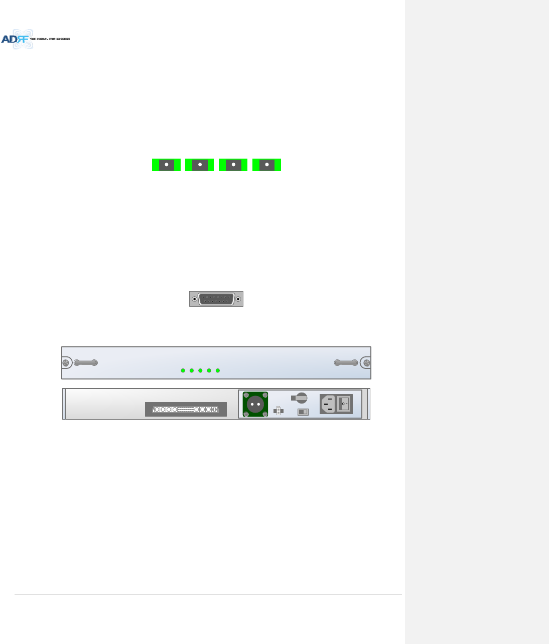
Figure3‐12ADX‐H‐ODU4andADX‐H‐ODU1InstalledinADX‐RACK‐ODU
Functions&Features
‐ ConvertssignalfromRFtoopticandtransportssignalsuptoamaximumof10Km(optical5dBo
lossincludingopticalconnectionloss).
‐ ADX‐H‐ODU4‐Xcansupportsupto(4)MainHPRsandupto5dBoopticalloss.
‐ ADX‐H‐ODU1‐Xcansupportsupto10dBoopticalloss.
‐ Minimizesthenumberofopticfibercableneedbytransportingmultibandsignalsoverasingle
strandoffiberusingWDMtechnology.
Spec
‐ Size:19.0x12.9x1.7inches(482x327x44mm)
‐ Weight:13.2lbs(6.0kg)
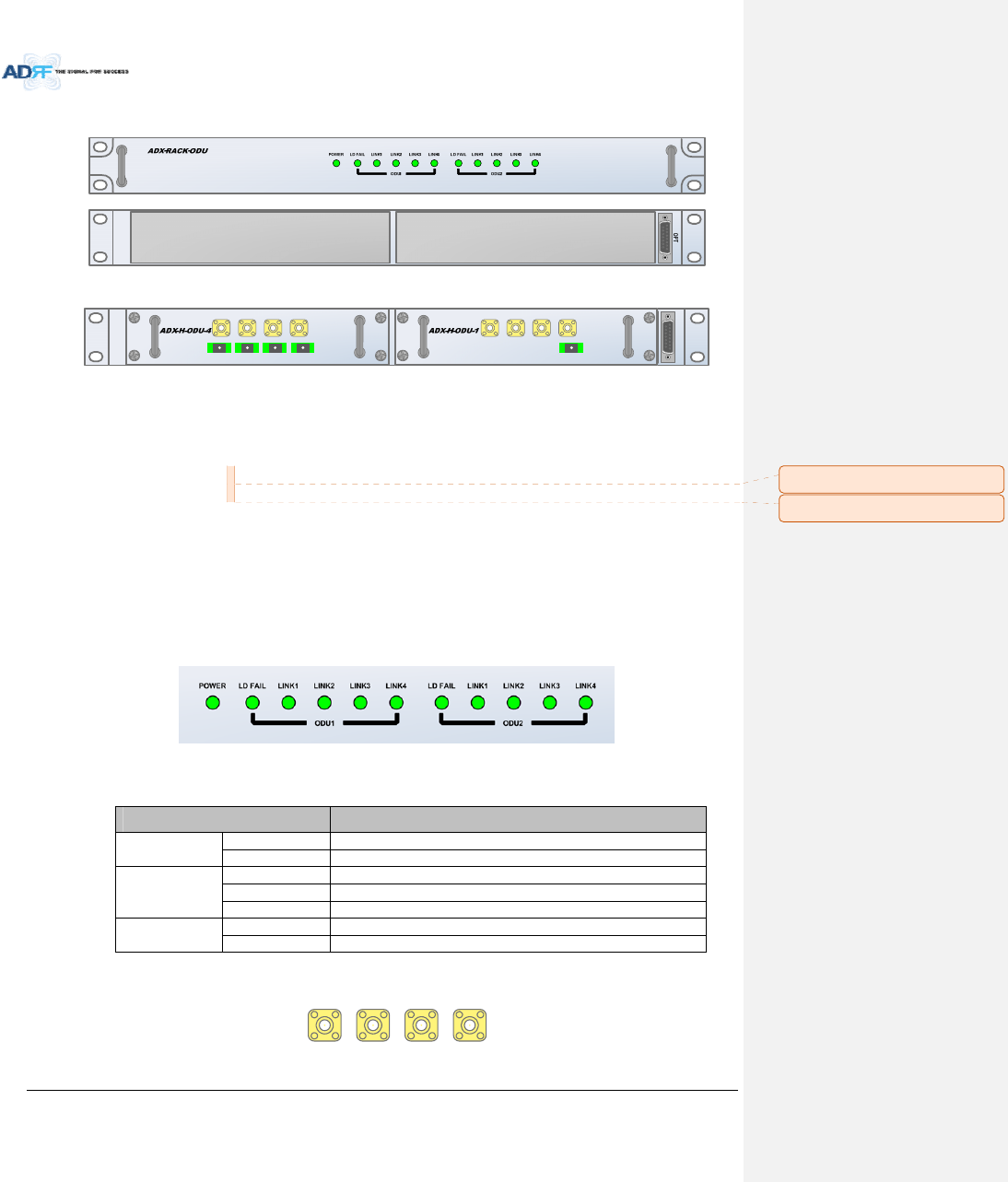
3.1.4.1 LEDs
TheADX‐RACK‐ODUhasthefollowingLEDsonthefrontpanelasshowninFigure3‐13.
Figure3‐13ADX‐RACK‐ODULED
Table3‐3ODULEDSpecifications
ADXDAS‐ModuleSpecifications
PowerSolidGreenModulepowerisON
OFF ModulepowerisOFF
LDFAILOFF ODUisnotinstalled
SolidYellowLDFailalarmexistsintheODU
SolidGreenNoLDFailalarmispresentintheODU
LINK1toLINK4SolidYellowPDFailalarmexists
SolidGreenNoPDFailalarmispresent
3.1.4.2 RFPorts
VHF UL 1 U L O U T 1VHF DL 1DL IN 1
Figure3‐14ODURFPorts
OPT
VHF UL UL OUT VHF DL DL IN
LINK 4LINK 3LINK 2LINK 1
VHF UL UL OUT VHF DL DL IN
LINK 4 LINK 3 LINK 2 LINK 1
VHF UL UL OUT VHF DL DL IN
LINK 1
메모 [H16]: ‐X추가
메모 [H17]: ‐X추가
AdvancedRFTechnologies,Inc. 33
3.1.4.2.1 DLIN/ULOUT
ThecombineddownlinksignalreceivedfromADX‐H‐CHCistransferredtotheDLIN1(or2)atthebackofODU.
TheULOUTportconnectsanyoftheportsonbackoftheADX‐H‐CHClabeledUL1~8.
3.1.4.2.2 VHFDL/VHFUL
VHFDL/UHFULportsareusedtosupportPublicSafetyintheVHF&UHFfrequencybands.VHF/UHFsignals
forPublicSafetybypasstheADX‐H‐CHCandconnectdirectlytotheVHFDL/UHFULportsoftheADX‐H‐ODU.
3.1.4.3 OpticPorts
LI N K 4LINK 3LINK 2LINK 1
Figure3‐15ODUOpticPorts
TheADX‐H‐ODU4has(4)opticportsandcansupportupto(4)MainHPR’s.Likewise,theADX‐H‐ODU1has(1)
opticportsandcansupportupto(1)MainHPR.
3.1.4.4 CommunicationPort
ADX‐H‐NMSmonitorsandcontrolstheADX‐RACK‐ODUviathisport.DCpowerisprovidedfromtheADX‐H‐
PSUtotheADX‐RACK‐ODUviathisport.
OPT
Figure3‐16CommunicationPort(ODU)
3.1.5 PowerSupplyUnit(ADX‐H‐PSU)
ADX -H- PSU
P
OWE
R
CHG
S
TS
LOW BATT
AC
FA
IL
DC
FA
IL
OFF
Figure3‐17ADX‐H‐PSUFront&RearView
Functions&Features
‐ Capableofsupportingupto:
(8)ADX‐H‐RFUs
(4)ADX‐H‐BCU
(4)ADX‐H‐ODU
ADX‐H‐NMS
‐ SupporttheADRF‐BBUforanexternalbatterybackupsolution
Specificaitons
‐ Size:16.9x13.1x1.7inches
‐ Weight:7.7lbs
‐ PowerInput:110Vor220VAC,selectablebyswitch
3.1.5.1 LEDs
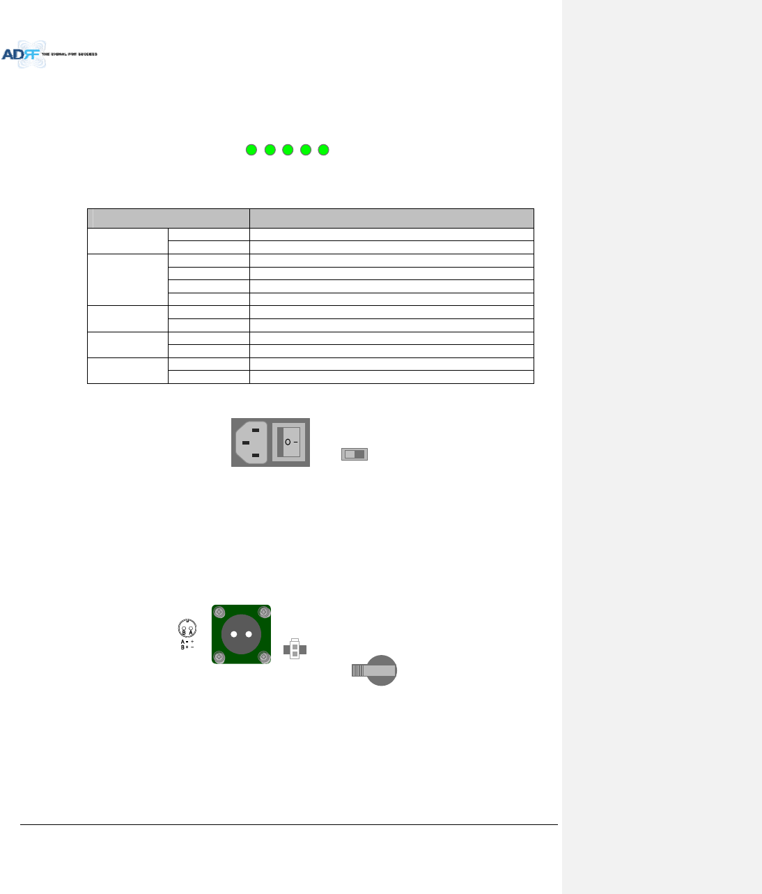
AdvancedRFTechnologies,Inc. 34
ADX‐H‐PSUhasthefollowingLEDsonthefrontpanelasshowninFigure3‐18.
P
OW
ER
CH
G STS
LOW
B
ATT
AC
FA
IL
DC
FA
IL
Figure3‐18HEPSULED
Table3‐4HEPSULEDSpecifications
ADXDAS‐ModuleSpecifications
PowerSolidGreenADX‐H‐PSUpowerisON
OFF ADX‐H‐PSUpowerisOFF
CHGSTSSolidYellowNoACpowerisavailableandADRF‐BBUisbeingused
BlinkingGreenPSUischargingtheADRF‐BBU
SolidGreenADRF‐BBUiscompletelycharged
OFF Batteryisnotconnected
LOWBATTSolidYellowLowBatteryalarmexistinthePSU
SolidGreenNoLowBatteryalarmispresentinthePSU
ACFAILSolidYellowACFailalarmexistsinthePSU
SolidGreenNoACFailalarmispresentinthePSU
DCFAILSolidYellowDCFailalarmexistsintheRFU
SolidGreenNoDCFailalarmsispresentinthePSU
3.1.5.2 ACInputOn/OffSwitch,ACInputPortandACInputSelectionSwitch
ON/OFFAC IN
AC SELECT
Figure3‐19HEPSUACInputOn/OffSwitch,ACInputPortandACInputSelectionSwitch
TheACPoweron/offswitchislocatedatthebackpanelofHEPSU.TheADX‐H‐PSUcanoperateat110VAC
and220VAC.TheusershouldverifythattheACinputvoltageswitchissettothecorrectvoltagebeforepowering
ontheADX‐H‐PSU.
3.1.5.3 BatteryBackupPort,BatteryInstallPortandBatteryBackupSwitch
BATTERY
INSTALL
BATTERY
24V 1A
BATTERY
OFF
S/WOFF ON
Figure3‐20BatteryBackupPort,BatteryInstallPortandBatteryBackupSwitch
TheBatterySwitchcanbeusedtoprovidepowertotheoptionalExternalBackupBattery(ADRF‐BBU)(Figure
3‐20).
TheADX‐H‐PSUcanbeconnectedtoanADRF‐BBU(ADRFBatteryBackupUnit)whichcanprovidepower
duringapoweroutage.IfanADRF‐BBUisutilized,connecttheADRF‐BBUtotheADX‐H‐PSUviatheexternal
batterybackupportasshowninFigure3‐20.
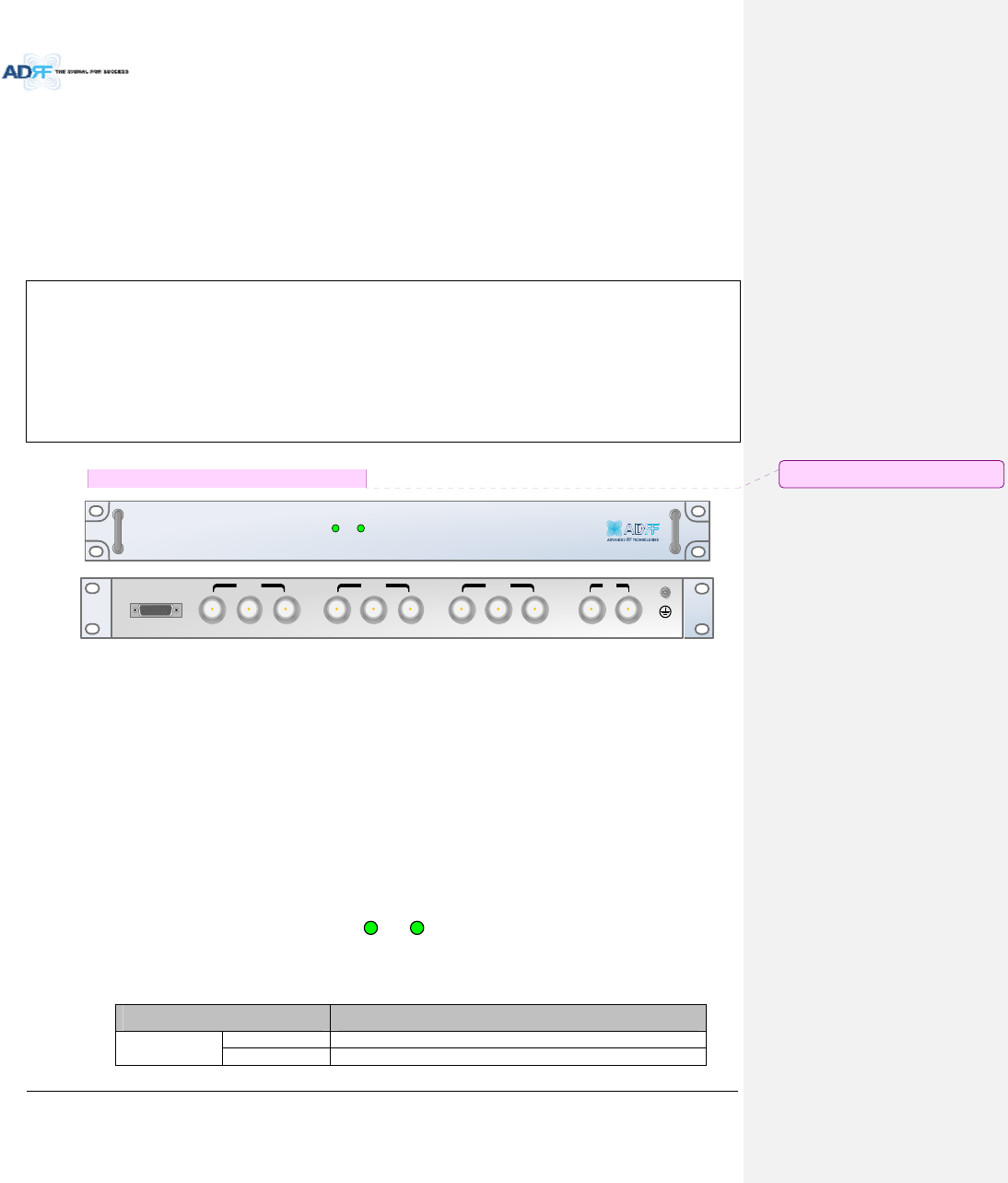
AdvancedRFTechnologies,Inc. 35
(WARNING:ThecircuitswitchontheADRF‐BBUmustbesettotheOFFpositionbeforeconnectingtheADRF‐
BBUtotheADX‐H‐PSUtopreventdamagetotheADX‐H‐PSUortheADRF‐BBUandpersonalinjury.)
Note:PleasecontactADRFTechnicalSupportforassistanceifyouareunfamiliarwiththeinstallation
procedureofourbatterybox.
TheBatteryInstallportisusedtoletADX‐H‐NMSknowifanADRF‐BBUisconnectedtotheADX‐H‐PSUornot.
IfanADRF‐BBUisconnectedwithoutthecableconnectiontoBatteryInstallport,theADX‐H‐NMSwillnotdetect
theADRF‐BBU.
TheprocedureforconnectingHEPSUtoBBU
BATTS/WOFF
ConnectADRF‐BBUtoHEPSUBatteryportandBatteryInstallportusingHEbattery
cable
BATTS/WON
3.1.6 OptionalBandCombinerUnit(ADX‐H‐BCU‐x)
SOFT FAILPOWER
ADX- H-BCU -P
DL IN 3
BAND COM
CH3 CH2 CH1 SUM
DPX 3UL OUT 3DL IN 2DPX 2UL OUT 2DL IN 1 DPX 1UL OUT 1 D L O U T U L I N
Figure3‐21ADX‐H‐BCUFront&RearView
Functions&Features
‐ Combinesandbalancesupto3carriers’signals
‐ Easilysupportsmultiplecarriers’signalsbyaddingasinglepieceofequipment
‐ Reducescomplexityandexpansioncoststosupportmultiplecarriers’signalsinasinglesystem
‐ Inputrange:+5~+25dBm
Specifications
‐ Size:19.0x12.9x1.7inches
‐ Weight:9.9lbs
3.1.6.1 LEDs
TheADX‐H‐BCUhasthefollowingLEDsonthefrontpanelasshowninFigure3‐22.
POWER SOFT FAIL
Figure3‐22BCULED
Table3‐5BCULEDSpecifications
ADXDAS‐ModuleSpecifications
PowerSolidGreenModulepowerisON
OFF ModulepowerisOFF
메모 [C18]: BCUH추가필요검토
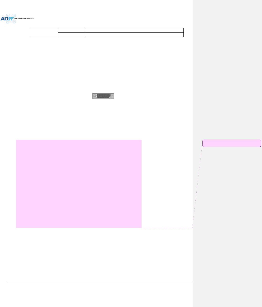
AdvancedRFTechnologies,Inc. 36
SoftFailSolidYellowSoftFailalarmexistintheRFU
SolidGreenNoSoftFailalarmsarepresentintheRFU
3.1.6.2 RFPorts
3.1.6.2.1 DLIN/ULOUT&DPXports
DLIN/ULOUT&DPXPortsarelocatedatthebackofBCUandconnectdirectlytoaBTS.
3.1.6.2.2 DLOUT/ULIN
DLOUT/ULINPortsarelocatedonthebackofADX‐H‐BCUandconnectdirectlytotheADX‐H‐RFU.
3.1.6.3 CommunicationPort
ADX‐H‐NMSmonitorsandcontrolstheADX‐H‐BCUviathisport.DCPowerisprovidedfromADX‐H‐PSUtothe
ADX‐H‐BCUviathisport.
BAND COM
Figure3‐23CommunicationPort(BCU)
3.2 HPR
‐ TheHighpowerremoteunitiscomposedofa(1)MainHPRandupto(1)ExtendedHPR.
‐ MainHPRandExtendedHPRusesameenclosure.
Figure3‐24ADX‐HPRSingleenclosure(bottomview)
3.2.1 Port
3.2.1.1 RFPort
3.2.1.1.1 Antennaserverport(DINtype)
메모 [C19]: 수정(CK)
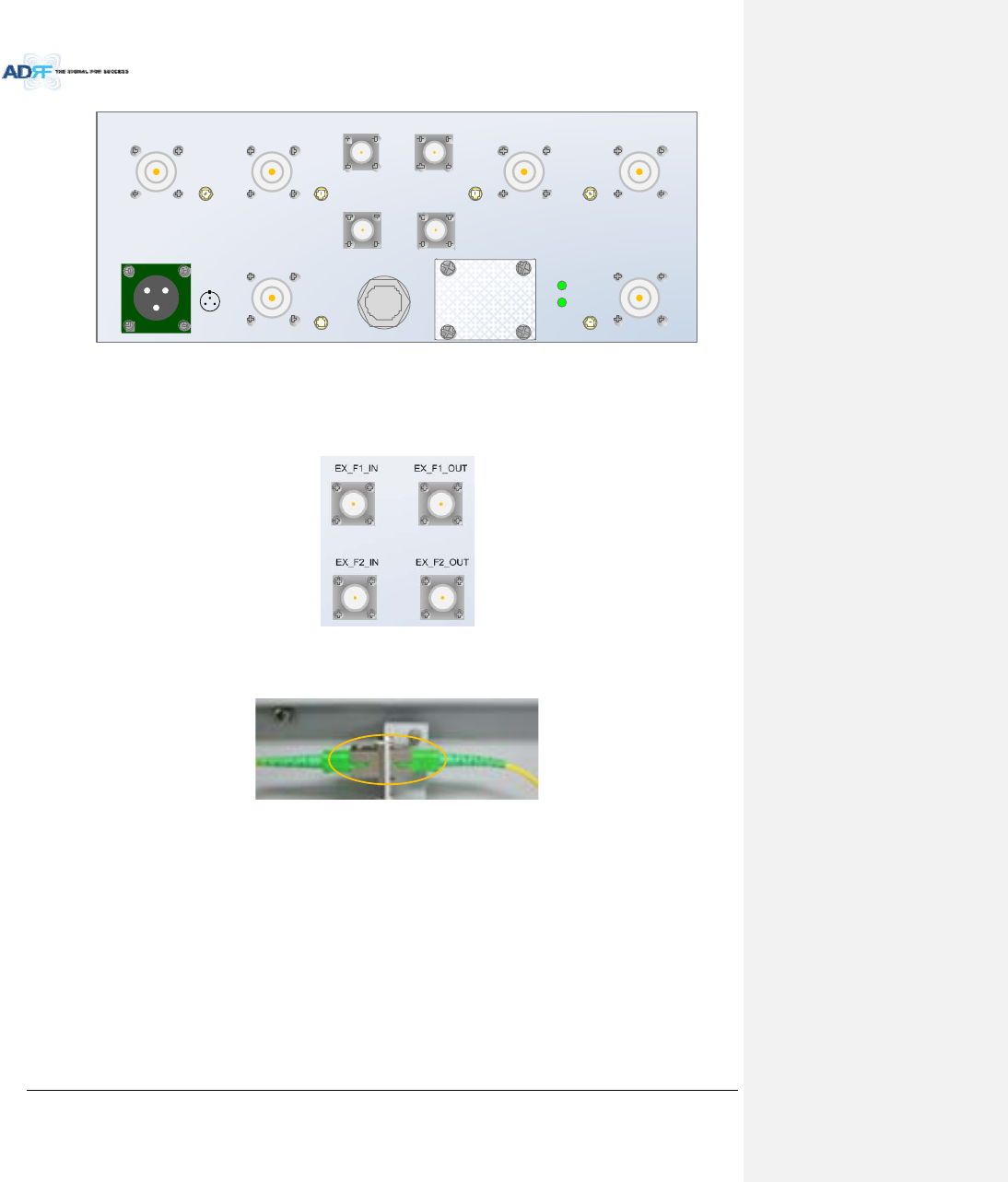
AdvancedRFTechnologies,Inc. 37
BAN D 1 SER VER BAN D2 SER VER
AC IN 110V
A
B
C
A = AC _L
B = A C _N
C = F. G
OPTIC
GUI
EX _F1 _IN
AB
EX_F1_O U T BAN D 3 SER VER BAN D 4 SER VER
CPL
(-30dB)
CPL
( -30dB)
CPL
(- 30dB )
CPL
(-30dB)
CPL
( -30dB)
CPL
(-30dB)
BAN D 6 SER VERBAN D5 SER VER
PO WER
RUN
EX_F2_IN EX _F2_O U T
3.2.1.1.2 ExtensionFilterport(Ntype)
‐ EX_F1_IN,EX_F1_OUT:extensionofadditionalFilterPort
‐ EX_F2_IN,EX_F2_OUT:extensionofadditionalFilterPort
3.2.1.2 Opticport
Figure3‐25InnerOpticportconnection
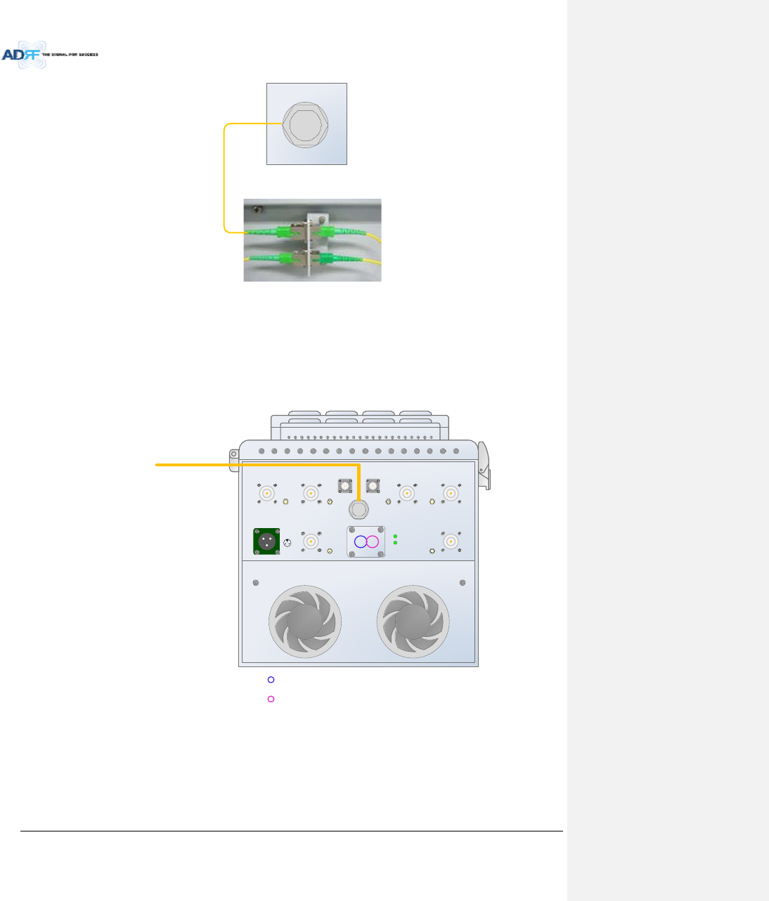
AdvancedRFTechnologies,Inc. 38
OPTIC
Figure3‐26Opticconnection
3.2.1.3 GUI,RS485port
‐ GUI_A,RS485_Aisforadditionalband(SISO,MIMO_1)
‐ GUI_B,RS485_Bisforadditionalband(MIMO_2)
‐ GUIconnectivityisalongwithopticlineposition(Seethepicturesbelowofvariouscombinations)
BAN D1 SER VER BAN D 2 SER VER
AC IN 110V
A
B
C
A = AC_L
B = AC_ N
C = F .G
OPTIC
GUI
EX _F_ IN
AB
EX _F_OU T BAN D3 SER VER BAN D 4 SER VER
CPL
(- 30dB )
CPL
(-30dB)
CPL
(-30dB)
CPL
(-30dB)
CPL
(-30dB)
CPL
(-30dB)
BAND6 SERVERBAN D 5 SER VER
PO WER
RUN
OPTIC LINE
Usable GUI PORT (SISO/MIMO_1)
Usable GUI PORT (MIMO_2)
Figure3‐27ADX‐HPR6bandsGUIconnection(Singleenclosure)
3.2.2 LEDs
HPRhasthefollowingLEDsonthefrontpanelasshowninFigure3‐28.
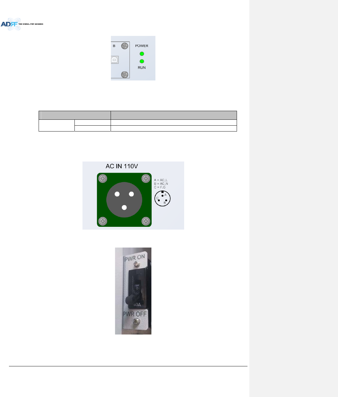
AdvancedRFTechnologies,Inc. 39
Figure3‐28HPRLED
Table3‐6MasterHPRLEDSpecifications
ADXDAS‐ModuleSpecifications
PowerSolidGreenModulepowerisON
OFF ModulepowerisOFF
3.2.3 ACOn/OffSwitch,ACPort
Figure3‐29HPRACPort
Figure3‐29HPRACSwitch
TheACPoweron/offswitchislocatedonPSUintheenclosureofeachADX‐HPR.
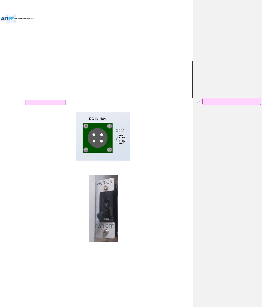
AdvancedRFTechnologies,Inc. 40
TheADX‐HPRisoperatedattheonly110VAC.
Thesocket‐outletshallbeinstalledneartheequipmentandshallbeeasilyaccessible
(WARNING:TheACswitchmustbesettoOFFbeforecableconnectiontoavoidequipmentdamageand
personalinjury.)
(WARNING:Toavoiddamage,besure110VACforoperationofADX‐HPR.)
(CAUTION:DOUBLEPOLE/NEUTRALFUSING.)
TheprocedureforconnectingHPR
ACS/WOFF
ACcableconnection
Opticconnection
RFcableconnection
RS485connection
ACS/WON
3.2.4 DCOn/OffSwitch,DCPort
Figure3‐30HPRDCPort
Figure3‐31HPRDCSwitch
TheDCPoweron/offswitchislocatedonPSUintheenclosureofeachADX‐HPR.
TheADX‐HPRisoperatedattheonly‐48VDC.
Thesocket‐outletshallbeinstalledneartheequipmentandshallbeeasilyaccessible
메모 [C20]: DC고려사항추가
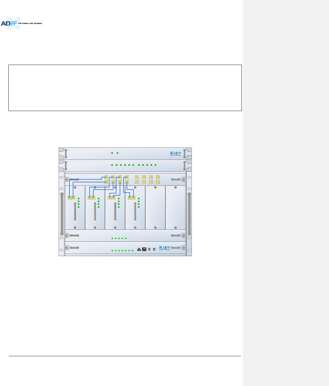
AdvancedRFTechnologies,Inc. 41
(WARNING:TheDCswitchmustbesettoOFFbeforecableconnectiontoavoidequipmentdamageand
personalinjury.)
(WARNING:Toavoiddamage,besure‐48V(‐36~‐76V)DCforoperationofADX‐HPR.
(CAUTION:DOUBLEPOLE/NEUTRALFUSING.)
TheprocedureforconnectingHPR
DCS/WOFF
DCcableconnection
Opticconnection
RFcableconnection
RS485connection
DCS/WON
4. CABLECONNECTION
4.1 HeadEndConnectionDiagrams
4.1.1 Front/RearHeadEndConnectionViewwithOptionalBCUunit
ADX- H-NM S
P
OWE
R
SO
FT FAIL-H
S
O
FT FAIL-R
H
ARD
FA
IL-H
HA
RD F AIL-R
LINK F AIL -H
LIN K
FA
IL-R
HOST HE VI EW
REMOTE RU V IEW
ADX- H-PSU
P
OWE
R
CHG S
TS
LOW
B
ATT
A
C FAIL
DC F AIL
DL OUTUL IN
HARD FAIL
DL S IG LOW
S O FT FA IL
POWER
ADX-H -RF U-P
DL OUTUL IN
HARD FAIL
DL SIG LOW
S O FT FA IL
POWER
ADX-H -RFU-7
DL OUTUL IN
HARD FA IL
DL SIG LOW
S O FT FA IL
POWER
ADX-H -RFU-C
DL OUTUL IN
HARD FAIL
DL SIG LOW
S O FT FA IL
POWER
ADX -H- RFU-A
ADX- H-CHC
UL1UL2UL3UL4
DL1DL2DL3DL4
UL5 UL6 UL7 U L8
DL5 DL6 DL7 D L8
LD FA IL5 -8 LI N K5 LI N K6 LI N K7 LI N K8LD FA IL1 -4 LI N K1 LI N K 2 LI N K3 LI N K4POWER
ADX- H-OPT
S O FT FA ILPOWER
ADX- H-BCU -P
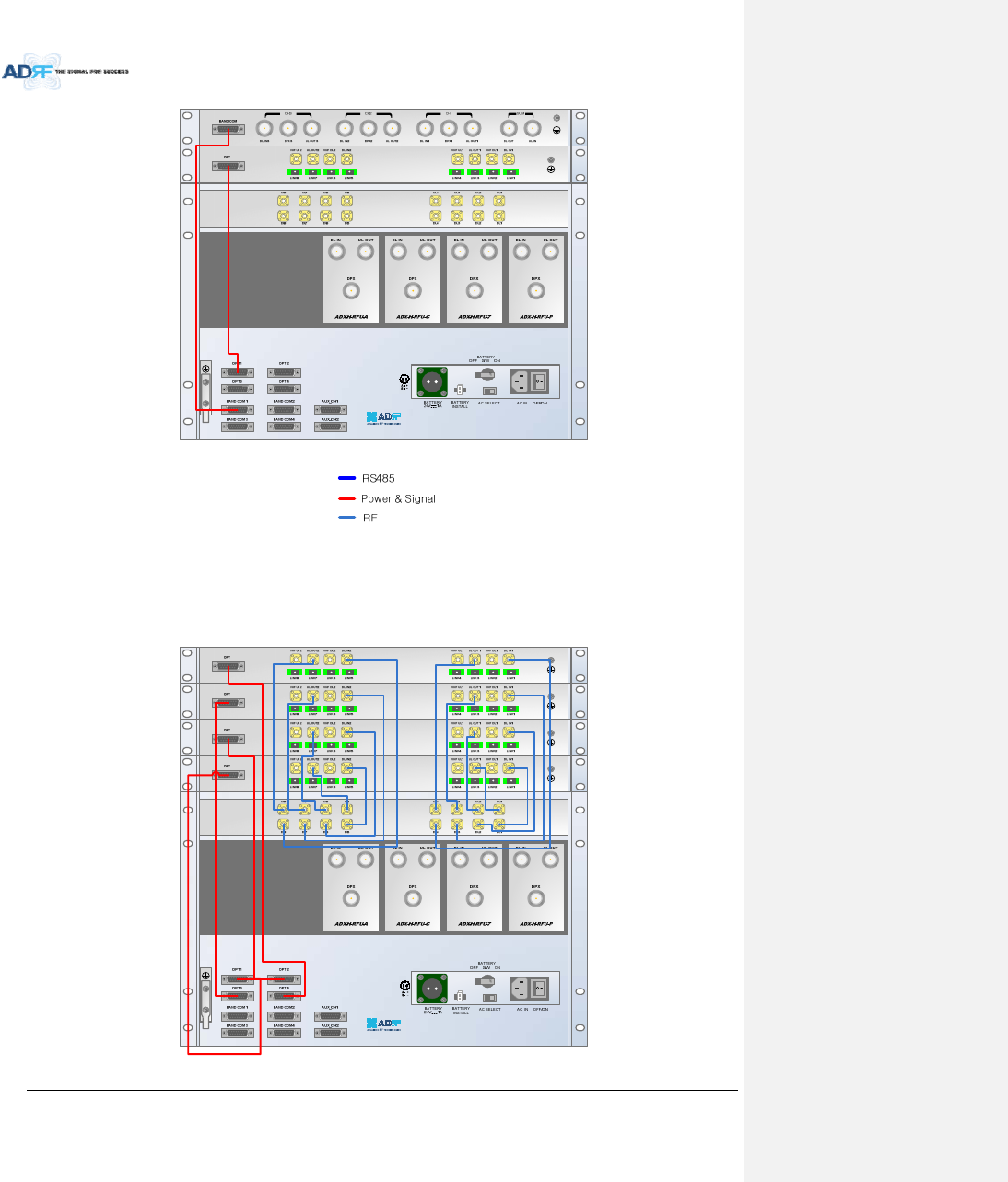
AdvancedRFTechnologies,Inc. 42
Figure4‐1HECableconnection(1ADX‐RACK‐ODU+1BCU)
4.1.2 RearHeadEndConnectionViewwith(4)ADX‐RACK‐ODUunits
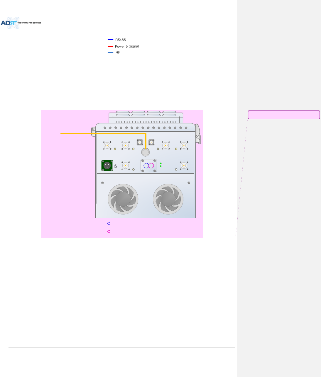
AdvancedRFTechnologies,Inc. 43
Figure4‐2HECableconnection(4ADX‐RACK‐ODUs)
4.2 HighPowerRemoteUnitConnectionDiagrams
‐ EthernetcableforRS485iscrossovertype
BAN D1 SER VER BAN D 2 SER VER
AC IN 110V
A
B
C
A = AC_L
B = AC_N
C = F.G
OPTIC
GUI
EX _F_IN
AB
EX _ F_O U T BAN D3 SER VER BAN D 4 SER VER
CPL
(- 30dB )
CPL
(-30dB)
CPL
(-30 dB)
CPL
(-30dB)
CPL
(-30dB)
CPL
(-30dB)
BAN D 6 SER VERBAN D 5 SER VER
PO WER
RUN
OPTIC LINE
Usable GUI PORT (SISO/MIMO_1)
Usable GUI PORT (MIMO_2)
Figure4‐3ADX‐HPR6bandsconnection(Singleenclosure)
WARNING!TheRS‐485portsshouldNEVERbeconnectedtotheEnthernetportoflaptoporEthernet
NetworkEquipment.DoingsomaycauseseriousdamagetotheRemoteModulesornetworkequipments.
메모 [C21]: 수정(CK)
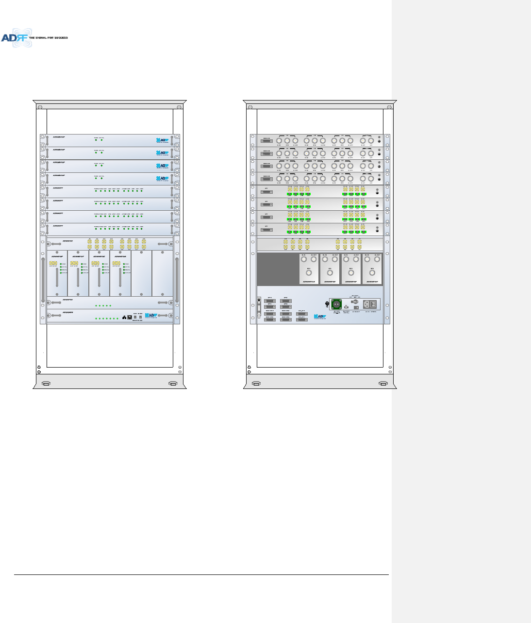
AdvancedRFTechnologies,Inc. 44
5. MOUNTINGMETHOD
5.1 HeadEnd
5.1.1 RackMount
Figure5‐1HERackMount(Front&Rearview)
Expandableupto4ADX‐RACK‐ODUs,4BCUsand2AUXCHs
POWER
SOFT FAIL-H
SOFT FAIL-R
HARD FAIL-H
HARD FAIL-R
LINK FAIL-H
LINK FAIL-R
POWER
CHG STS
LOW BATT
AC FAIL
DC FAIL
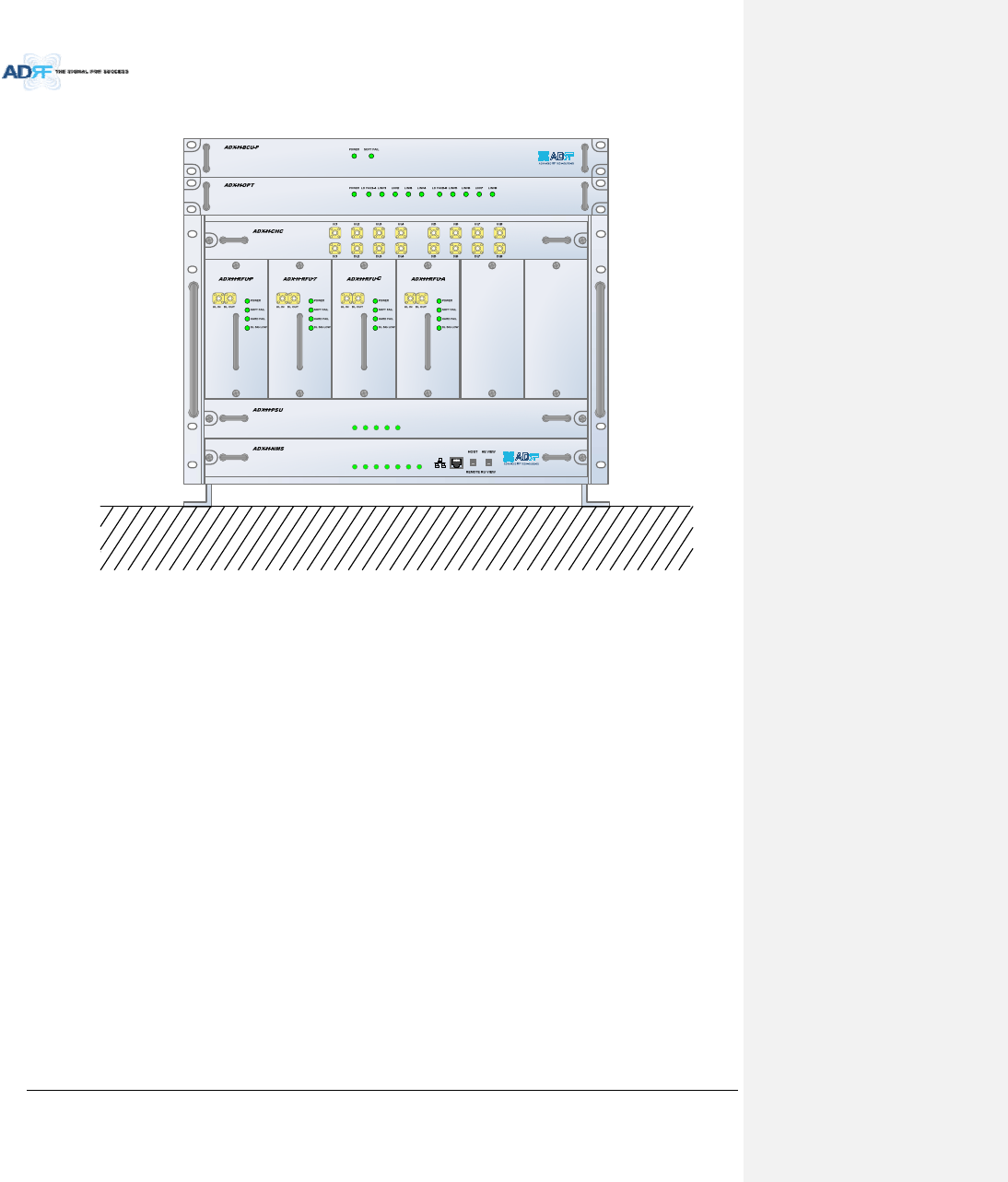
AdvancedRFTechnologies,Inc. 45
5.1.2 WallMount
Figure5‐2HEWallMount(TopView)
Expandableupto3units(ODU,BCU)ormax3U(132mm)
‐ ODUorBCUwillbestackedupabovebasic19”HEchassiswhichincludesNMS,RFU,PSUand
CHC
POWER
SOFT FAIL-H
SOFT FAIL-R
HARD FA IL-H
HARD FAIL-R
LINK FAIL-H
LINK FAIL-R
POWER
CHG STS
LOW BATT
AC FAIL
DC FAIL
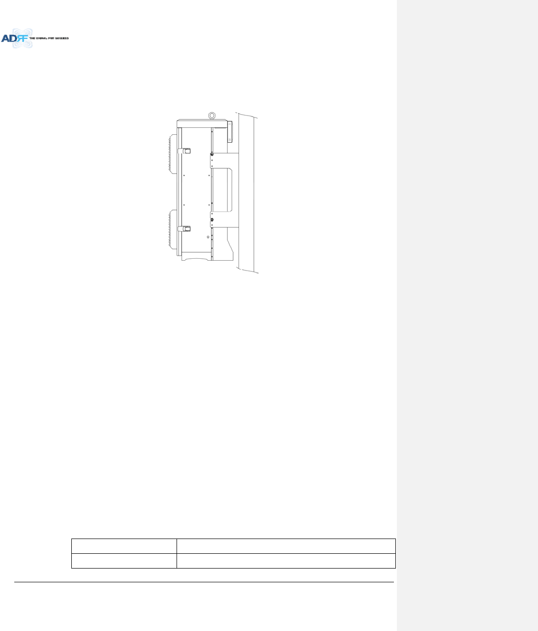
AdvancedRFTechnologies,Inc. 46
5.2 HPR
5.2.1 WallMount
ADX‐HPRissupportonlywallmount.
Figure5‐3HPRWallMount
6. INSTALLATION
6.1 Pre‐InstallationInspection
PleasefollowtheseproceduresbeforeinstallingADXHPRequipment:
o Verifythenumberofpackagesreceivedagainstthepackinglist.
o Checkallpackagesforexternaldamage;reportanyexternaldamagetotheshippingcarrier.If
thereisdamage,ashippingagentshouldbepresentbeforeyouunpackandinspectthecontents
becausedamagecausedduringtransitistheresponsibilityoftheshippingagent.
o Openandcheckeachpackageagainstthepackinglist.Ifanyitemsaremissing,contactADRF
customerservice.
o Ifdamageisdiscoveredatthetimeofinstallation,contacttheshippingagent.
o VerifytheACvoltagewithDVM(Voltmeter)is110VAC.IncorrectACvoltagecandamagethe
ADXequipment.
o Thispowerofthissystemshallbesuppliedthroughwiringinstalledinanormalbuilding.If
powereddirectlyfromthemainsdistributionsystem,itshallbeusedadditionalprotection,such
asovervoltageprotectiondevice.
o Overvoltagecategory(OVC)&Pollutiondegree(PD)
Overvoltagecategory(OVC)OVCII
Pollutiondegree(PD)PD2

AdvancedRFTechnologies,Inc. 47
6.2 ADXDASInstallationProcedure
6.2.1 HEInstallationProcedure
CAUTION: ADXDASHEshouldbeinstalledinsidebuildingonly.
6.2.1.1 InstallingaADXDASHEinarack
TheADXHEchassismountsinastandard19”(483mm)equipmentrack.Allowclearanceof3”(76mm)atthe
frontandrear,and2”(51mm)onbothsidesforaircirculation.Notoporbottomclearanceisrequired.
Consideration:
‐ Eightmountingholesarelocatedon4cornersofADXHEtoattachittothe19”rack.TheADXHE
mustbesecurelyattachedtoarackthatcansupporttheweightoftheADX.
Mountprocedure
‐ ThefollowingstepsshouldbefollowedwhilemountingtheADXHE
DetachthewallmountbracketassembledlocatedatthebaseoftheADX‐HEchassis
VerifythattheHEandMountingholesareingoodcondition
SettheADXDASHEagainstthe19”rackandsecuretheunitwithscrews
VerifythatADXHEissecurelyattached
ConnecttheGNDcable
ConnecttheRFcable
ConnectthePower
ConnecttheOpticcable
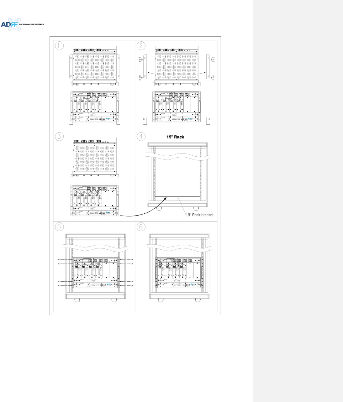
AdvancedRFTechnologies,Inc. 48
Figure6‐1ADXHE19”RackMountInstructions
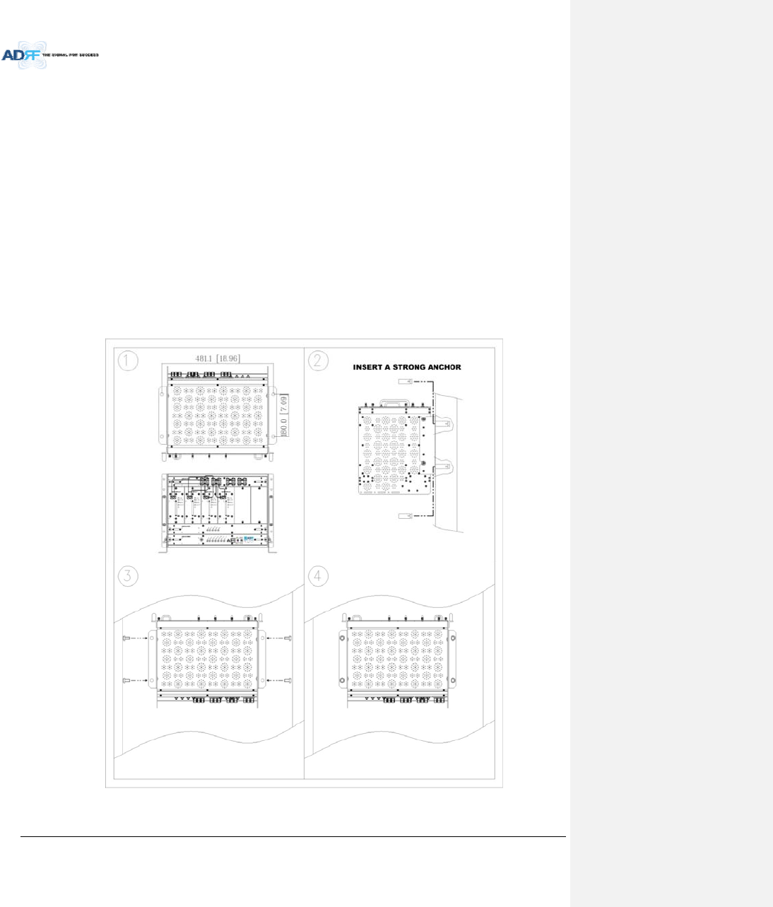
AdvancedRFTechnologies,Inc. 49
6.2.1.2 WallmountingtheADXDASHE
IftheADXHEchassisisbeingmountedtoawall,thenallowclearanceofatleast17”(430mm)onthetop
(frontsideofHE)and2”(51mm)onthebottom(rearsideofHE)and2”(51mm)onbothsidesandfrontforair
circulation.
Mountprocedure
‐ ThefollowingstepsshouldbefollowedwhenwallmountingtheADXHE
VerifythattheHEandMountingholeareingoodcondition
PlacetheADXHEagainstthewallandmarkofthemountingholes
Drillholes(4holes,18Φmm,50mmdepth)intheinstallationsurfaceandinserttheanchorbolts
BolttheADXHEtothewall
MakesuretheADXHEissecurelyattached
ConnecttheGNDcable
ConnecttheRFcable
ConnectthePower
ConnecttheOpticcable
Figure6‐2ADXHEWallMountInstructions
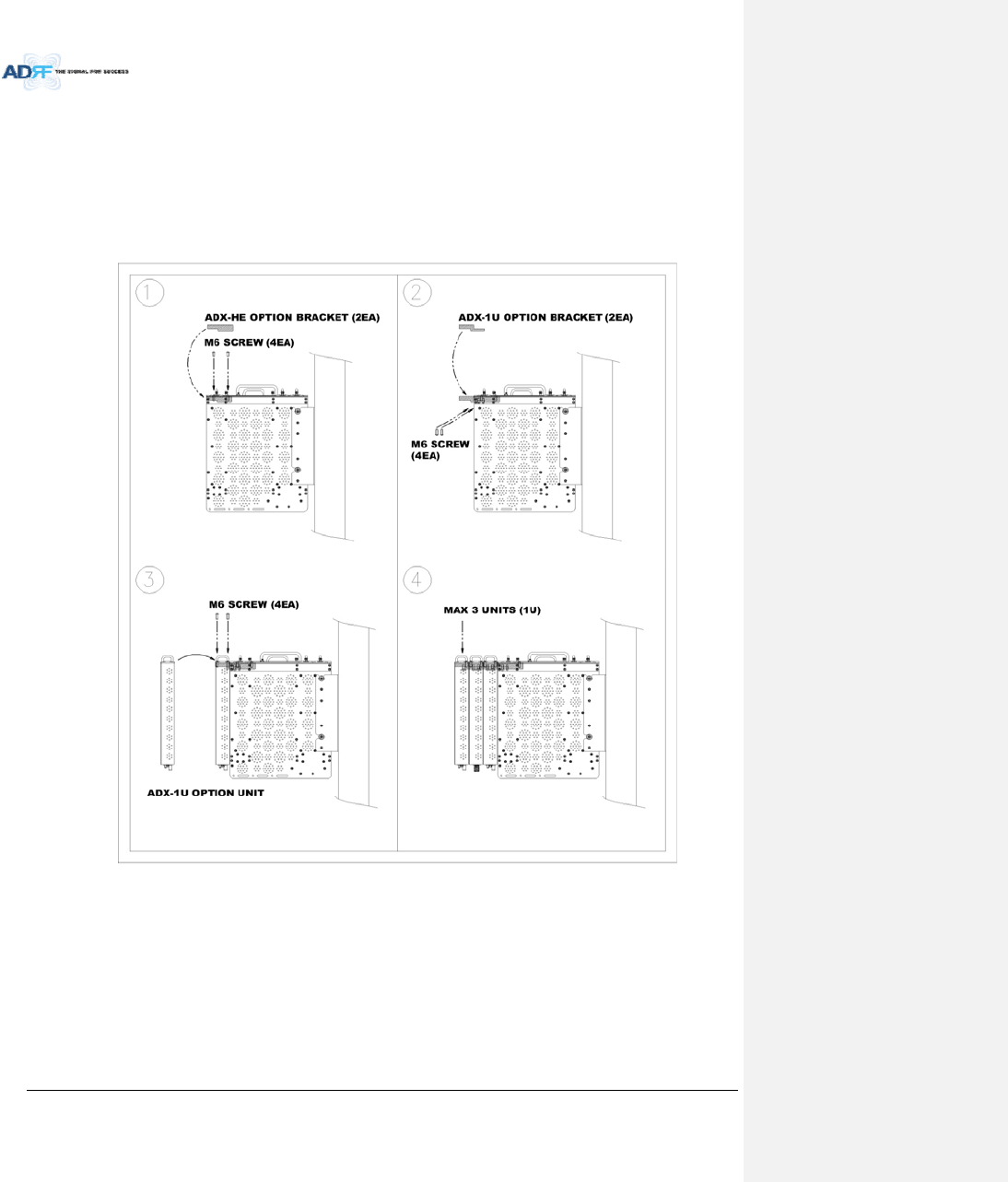
AdvancedRFTechnologies,Inc. 50
6.2.1.2.1 InstallingaddedracktypemodulesintobasicHEchassis
AdditionalmodulessuchastheADX‐RACK‐ODUandADX‐H‐BCUcanbemountedtotheChassis(ADX‐H‐CHA)
usingtheincludedmountingbracketsthatcomewiththeadd‐onmodules.
Amaximumofupto3addonmodules(ODU,BCU)canbemountedtothechassis
‐ ODUorBCUwillbestackedupabovebasic19”HEchassiswhichincludesNMS,RFU,PSUand
CHC
Figure6‐3WallMountInstructionsforADX‐HEadded1UUnit

AdvancedRFTechnologies,Inc. 51
6.2.2 RUInstallationProcedure
WallmountingtheADXHPR
Mountprocedure
‐ ThefollowingstepsshouldbefollowedwhilemountingtheRemoteModule
VerifythattheHPRandMountingholeareingoodcondition
SeparatethewallmountbracketfromtheHPR
Placedthewallmountbracketagainstthewallandmarkoffthemountingholes
Drillholes(4holes,18Φmm)intheinstallationsurfacetheninserttheenclosedanchorbolts
Boltthemountingbrackettothewall
InstalltheHPRtothemountingbracket
FastentheHPRtothemountingbracketusingtheincludedscrews
VerifythattheHPRissecurelyattached
ConnecttheAntennacable
ConnectthePower
ConnecttheOpticcable(ifapplicable)
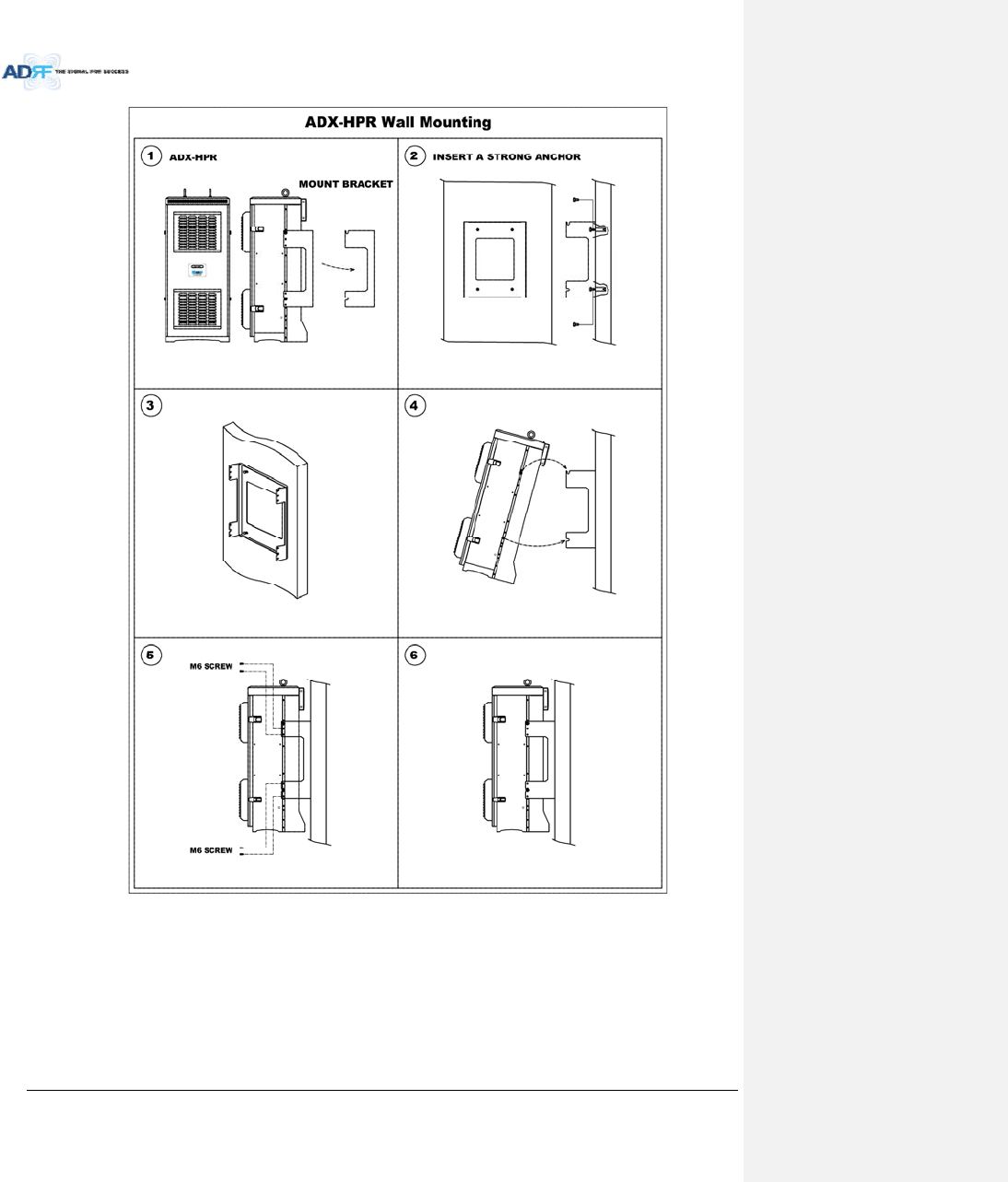
AdvancedRFTechnologies,Inc. 52
Figure6‐4HPRWallMountInstructions
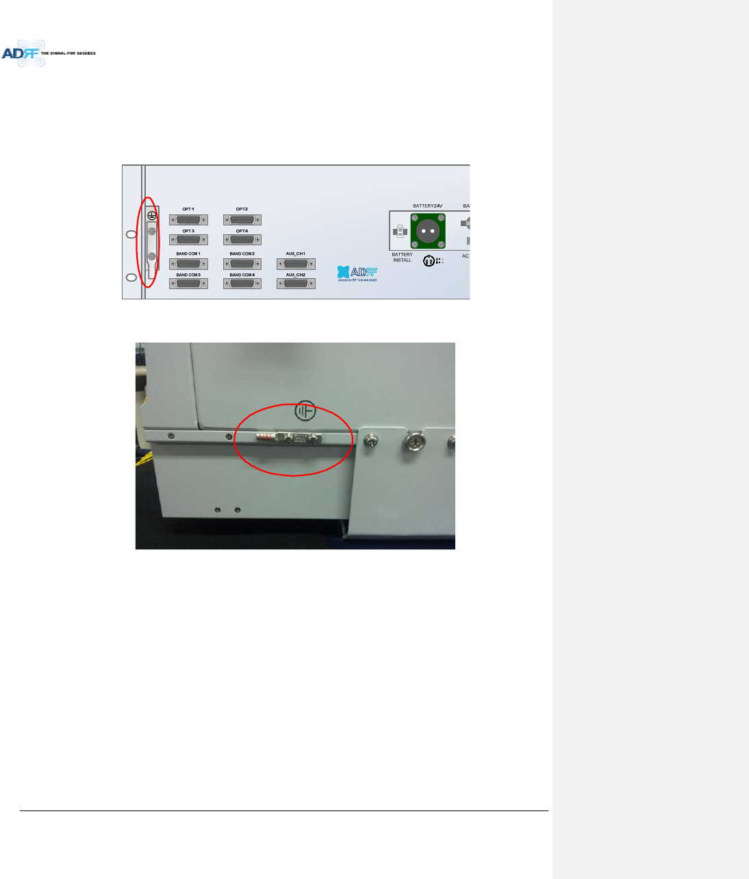
AdvancedRFTechnologies,Inc. 53
6.3 Grounding
Agroundcableisincludedinthebox.ThegroundingterminalsarelocatedattherearoftheADXHEandRU.
Thegroundingcableshouldbeproperlyconnectedbeforepoweringontheequipment.
Figure6‐5GroundCableConnection(HErearside)
Figure6‐6GroundCableConnection(HPRdualside)
Roundterminalslocatedonthesideofa1.25mm²(16AWG)ormorewiresUsingpermanentlyconnectedto
earth.
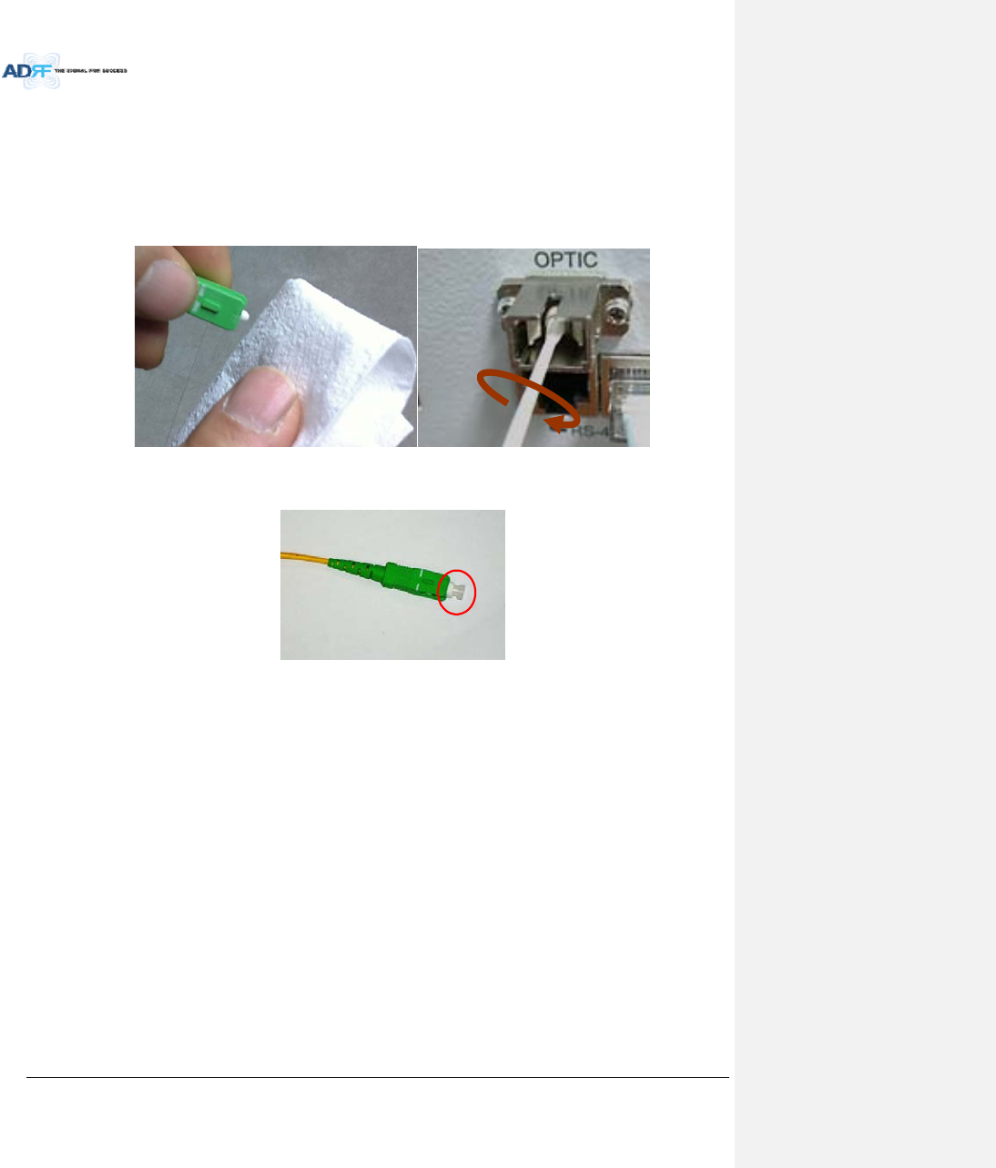
AdvancedRFTechnologies,Inc. 54
6.4 OpticPortCleaning
Werecommendcleaningopticconnectorusingadryopticalcleaningswabortissueinadryenvironmentas
needed.Werecommendcleaningtheopticconnectorsonlyiftheexpectedopticlossishigherthantheloss
reportedintheWeb‐GUIby1.5dBo.(Figure6‐7)
Whenopticconnectorarenotinuse,theportshouldbecoveredwithaprotectivedustcap.(Figure6‐8)
Figure6‐7OpticConnectorCleaning(left)andOpticPortCleaning(right)
Figure6‐8SC/APCOpticConnectorDustCap

AdvancedRFTechnologies,Inc. 55
7. COMMISSIONING
Thecommissioningprocessiscomposedofthefollowing:
‐ Pre‐CommissioningCheck(refertosection7.1)
‐ OpticCommissioning(Opticlosscompensation)(refertosection7.2.1)
‐ HEcommissioning(refertosection7.2.2)
‐ RUcommissioning(refertosection0)
‐ Commissioningverification(refertosection0)
7.1 Pre‐CommissioningCheck
7.1.1 Verifycableconnections
Beforepoweringupunits,checkallRFcables,fibercables,andpowercablesconnections.
AllpowerLEDsshouldbelit1minuteafterthecomponentshavebeenturnedon.
CheckwhetherLD&PDLEDsofHEODUmodulesaresolidGREEN.(PDLEDwillbelitgreenwhenconnectedto
aMasterRU).
‐ IfthePDLEDforthelinkwithaconnectionwithtoaHPRisOFF,thenchecktheopticcable
connection.
‐ IftheopticcableisgoodandthePDLEDisnotlitgreen,thetryanotheropticportontheADX‐
RACK‐ODUtoseeiftheotherportlightsupgreen.
7.1.2 ConnecttotheWeb‐GUI
ConfirmthattheNMSHost/RemoteswitchissettotheHostposition
ConfirmthattheHEView/RUViewswitchissettotheHEViewposition
ConnecttheRJ‐45crossovercablefromtheEthernetportofNMStotheEthernetportoflaptop
LaunchastandardInternetbrowserlikeIEorGoogleChromeandtypetheSystemController’sIPaddress
(192.168.63.1)intotheaddessbar
Ontheloginscreenusethefollowingdefaultlogin/passwordtogainaccess:
‐ Username:adrf
‐ Password:adrf
Figure7‐1Loginwindow
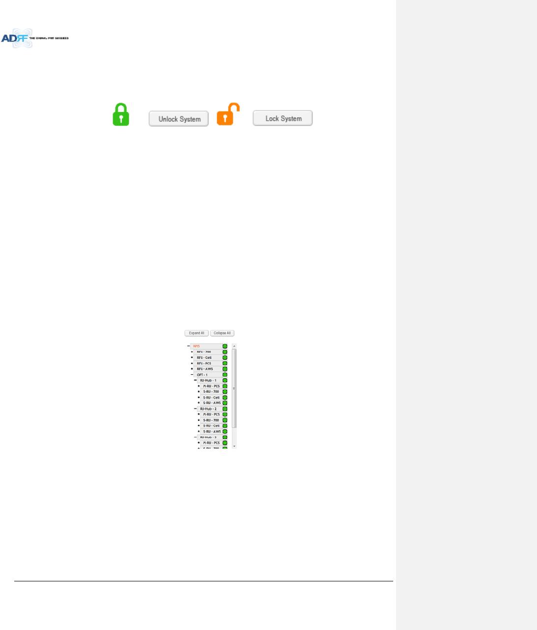
AdvancedRFTechnologies,Inc. 56
7.1.3 CheckNavigationTreeStatus
CheckwhetherthestatusofnavigationtreeisLockorUnlock.
Thenavigationtreeshouldbeinthe“Unlock”stateinwhenaddingorremovingactiveADXcomponents.
Figure7‐2NavigationtreeLock/Unlock
Whenthesystemislocked:
Unabletodetectanyhardwarethatisadded
Abletodetectanylinkfails(communicationerrorsbetweenNMSandcomponents)
Systemshouldbelockedafterfinalcommissioning
Whenthesystemisunlocked:
UnabletoperformBCU,RFU,orHPRcommissioning
Systemiscontinuallyscanningfornewhardware
7.1.4 SetLocationInfo,InstallerInfoandDate&Time
GototheInstallpageofNMS
EnterLocation&installerinformation
SetcurrentDate&Time
7.1.5 VerifyNavigationTreeLinks
CheckwhetherallunitsconnectedtoHE&HPRarebeingdisplayedinthenavigationtree.
‐ NavigationtreeislocatedontheleftsideofWeb‐GUI(Figure7‐3)
Figure7‐3Navigationtree
Checkwhetherlinkfailsexist.LinkfailsstatuscanbeseenonthefrontpanelofNMSmoduleviatheLinkFail‐
HandLinkFail‐RLEDlights.
‐ IfLINK‐Hfailexists,powercycletheHEPSUandcheckifLINK‐Hfailisstillpresentandrepeatthis
stepupto3timesoruntilthealarmclears.IfLINK‐Hfailstillexistsafter3powercycles,then
contactADRFTechnicalsupport.
‐ IfLINK‐Rfailexists,powercycletheADX‐H‐ODUmodulewhichisconnectedtotheMasterHPR
withlinkfailandchecktoseeiftheLINK‐Rfailisstillpresentandrepeatthisstepupto3timesor
untilthealarmclears.IfLINK‐Rfailstillexistsafter3powercycles,contactADRFTechnical
support.

AdvancedRFTechnologies,Inc. 57
7.1.6 BOMComparison&CheckBandConfiguration
BOMcomparison
‐ OntheSysteminformationpageintheSystemmenu,thelistofallcomponentsconnectedtothe
ADX‐H‐NMSshouldmatchtheADXNavigationtree.ThislistcanbeusedtoverifyBOMgenerated
bydesignerorinstallerforallactivecomponents.Pleasenotethatpassivecomponentssuchas
theADX‐H‐CHC,ADX‐R‐CHC,ADX‐H‐PSU,andtheADX‐R‐4WSwillnotshowuponthisreport.
CheckBandConfiguration
‐ CheckwhetherthebandconfigurationofADX‐H‐RFUisidenticaltothebandconfigurationofthe
ADXHPRunits.AnydiscrepancieswillappearintheSystemInformationreport.
‐ Checktoseeiftherearemultipleremotemoduleswiththesamefrequencybandswithin1
remoteunit.ThisinformationisdisplayedontheSystemInformationpageintheSystemmenu
asnotificationmessage.
7.1.7 Lockcurrentnavigationtree
IftherearenoerrorsintheprocessofBOMComparison&CheckBandConfiguration,thenlocktheNavigation
Treebyclikingonthe“LockSystem”button.
‐ AfterlockingtheNavigationTree,linkfailalarmsshouldnotappear.Iflinkfailalarmsare
present,pleasecheckthephysicalconnectionofthedevicewiththelinkfailalarm.
‐ Thesystemmustfirstbeplacedinthe“Unlock”statebeforeaddinganynewdevices.Newly
addeddeviceswillappearintheNavigationTreewhenthepageisrefreshed.Onceallnew
hardwarehasbeenaddedtotheNavigationTree,thetreemustbelockedbeforecommissioning
thesystem.
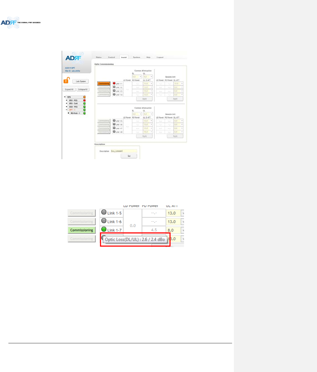
AdvancedRFTechnologies,Inc. 58
7.2 Commissioning
7.2.1 OpticCommissioning
Figure7‐4ODUInstallpage
NavigatetotheInstallpageofADX‐H‐ODU(Figure7‐4)
Comparethevaluesofmeasuredopticloss(LDpower–PDpower)intheWeb‐GUIwiththeactualopticloss
whichistypicallymeasuredatthetimeofinstallationofthefiber.
‐ ThecalculatedopticlossisdisplayedwhenthemousepointerisplacedovertheStatusindicator
ofeachlink
Figure7‐5measuredopticlossdisplay
‐ Ifthedifferencebetweenthemeasureopticlossandthecalculatedlossislargerthan1.5dBo,
thencleantheopticconnectorandopticportusingopticalcleaningswab.(refertosection6.4)
ThefollowingisthedefinitonoftheStatusindicatorofeachlink:
‐ Green:Indicatesthatopticlossislessthan5dBo
‐ Orange:Indicatesthatopticlossisgreaterthan5dBo
‐ Gray:NoMasterHPRisconnectedtothislink.
ThefollowingisthedefinitionforthebackgroundcoloroftheCommissioningbutton:
‐ Green:Indicatesthatnoopticlosscompensationisneeded.
‐ Orange:Indicatesthatopticlosscompensationisneeded.
‐ Gray:NoMasterHPRisconnectedtothislink.
7.2.1.1 Howtocompensatetheopticloss

AdvancedRFTechnologies,Inc. 59
Opticlosscompensationshouldbeperformedwhenthecolorof“Commissioning”buttonisorange.The
“Commissioning”buttonwillturnorangewhenthedifferencebetweenthecompensatedattenuationandthe
actualcompensatedattenuationlevelisgreaterthan1.5dB.Opticcompensationcanbeperformedbyclickingthe
orange“Commissioning”button.
Theopticlosscompensationforuplinkanddownlinkareperformedseparately.
‐ TheopticlosscompensationfordownlinkwillbeperformedbasedontheLDleveloftheODU
andthePDleveloftheMasterRU.
‐ TheopticlosscompensationforuplinkwillbeperformedbasedontheLDleveloftheMaster
HPRandthePDleveloftheODU.
OpticlosscompensationadjuststheattenuationbasedonTable7‐1andthecalculatedopticloss(LDlevel‐PD
Level).
‐ Thecalculatedopticlossisdisplayedwhenamouseisplacedonthecircleofeachlink.(Referto
section7.2.1.1)
‐ Basedonthetablebelow,whenthecalculatedopticlossis1dB,theattenuationwillbesetto
11dB.
‐ TheattenuatorfordownlinkopticlosscompensationislocatedattheMasterRU.
‐ TheattenuatorsforuplinkopticlosscompensationarelocatedattheODU.
Table7‐1Opticlosscompensationtable
OpticLoss(dBo)CompensatedAttenuation(dB)
013
0.5 12
111
29
37
45
53
Example:Let’ssaythatthisADX‐H‐ODUhadpreviouslybeencommissionedinasystemwheretheopticloss
was3dBo.Intheprevioussystem,thecorrectamountofattenuationis7dB.TheADX‐H‐ODUwasmovedto
anothersiteandthenewsystemhasanopticlossofonly1dBo.At1dBoofloss,thecorrectamountof
attenuationshouldbe11dB.Whenthissystempowerson,opticcommissioningwillneedtobeperformed
becausethedifferencebetweentheoldattenuationlevelandthenewattenuationlevelis4dBwhichexceeds
the1.5dBthreshold.Onceopticcommissioningisperformed,itwillsettheattenautionlevelto11dB.

AdvancedRFTechnologies,Inc. 60
7.2.2 HECommissioning
HEcommissioningiscomposedofHEBCUandHERFUcommissioning.TheHEBCUisanoptionalcomponent
andshouldbeusedwhenWPSs’signalsarebeingusedinthesamefrequencyband.
7.2.2.1 Compositepower
ToperformHEcommissioning,theusershouldcalculatedownlinkcompositeinputlevelandaddtheproper
amountofbreathroomrequiredforriseintraffic.
Informationthatisneededtocalculatecommissioninglevelsare:
‐ Servicefrequencyband
‐ Servicetechnology
‐ Thenumberofwirelessserviceprovider
‐ Thenumberofcarrierspertechnology
‐ Thenumberofbandsharingsameamplifier
7.2.2.1.1 DLCompositeInputLevelCalculationsforHECommissioning
7.2.2.1.1.1 SingleWSPinafrequencyband
MeasuretheoutputpoweroftheBTSsignalthatwillbeinsertedintotheRFUusingaSpectrumAnalyzer.
‐ Ifinputsignalincludesmorethanonetechnology,thenmeasurethecompositepowerofeach
technology.
BasedonTable7‐2,calculatethemaximumcompositeinputlevelbyusingthefollowingformula:
o “OutputpowerofBTSoftechnologybeingused”+“back‐offvalue”(refertoTable7‐2)
‐ IfcalculatedcompositeHEDLinputpowerexceedsthepermittedmaximuminputrange,then
additionalattenuationwillneedtobeaddedsothatthecalculatedHEDLinputpowerdoesnot
exceed25dBm.
Table7‐2Back‐offvalueforeachtechnologyduetotrafficbreathing
TechnologyConnectedtoBTS
CDMA6~8dB
1xEVDO6~8dB
WCDMA8~10dB
HSPA8~10dB
iDEN0~3dB
GSM0~3dB
LTE8~10dB
7.2.2.1.1.2 MultipleWSPsinafrequencyband
WhenmultipleWSPsexistinafrequencybandatthesametime,theADX‐H‐BCUcanbeusedto
combine/dividethesignalsreceivedfrommultipleWSPs.
‐ TheADX‐H‐BCUcanreceiveupto3incomingDLsignals.Eachincomingsignalcanbeattenuated
individuallyallowingtheusertospecifypowerratiostocontrolthepowerpercarrier.
‐ ThedownlinkpathofBCUhastheinputrangefrom0to25dBm.
‐ IfthedownlinkoutputofBCUexceedsDLoutputALClevelsetbyuser,ALCfunctionwillactivate
andlimittheDLoutputfromexceedingthedefinedALClevel.
‐ TheDLoutputofADX‐H‐BCUistransferredtotheDLinputofRFU.
MeasuretheoutputpoweroftheBTSsignalthatwillbeinsertedintotheBCUusingaSpectrumAnalyzer.
‐ Ifinputsignalincludesmorethanonetechnology,thenmeasurethecompositepowerofeach
technology.
BasedonTable7‐2,calculatethemaximumcompositeinputlevelbyusingthefollowingformula:
o “OutputpowerofBTSoftechnologybeingused”+“back‐offvalue”(refertoTable7‐2)
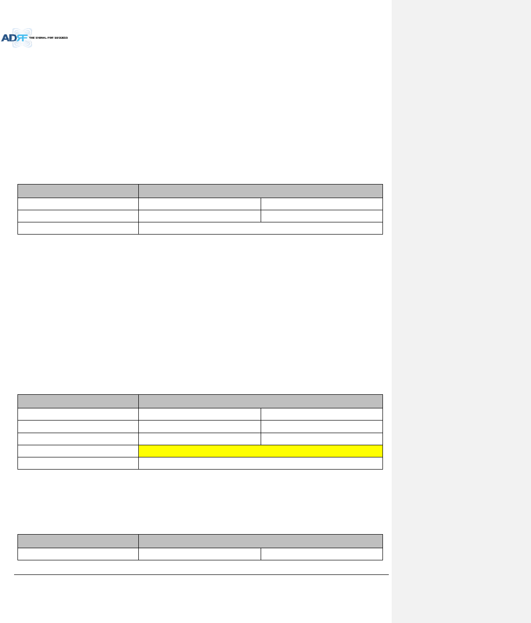
AdvancedRFTechnologies,Inc. 61
‐ IfcalculatedcompositeHEDLinputpowerexceedsthepermittedmaximuminputrange,then
additionalattenuationwillneedtobeaddedtotheBCUinputportsothatthecalculatedHEDL
inputpowerdoesnotexceed25dBm.
TheRFUDLinputcommissionlevelisthecombinedDLOutputALCLeveloftheADX‐H‐BCUwhichcanbe
obtainedfromtheControlpageoftheADX‐H‐BCU.
‐ ThemaximuminputlevelofHERFUwillnotexceed10dBm(=5dBm+10*log10(3))becausethe
maximumoutputofBCUeachpathislimitedto5dBmbytheALCfunction.
7.2.2.1.2 Exampleofcommissioningvaluecalculation
7.2.2.1.2.1 AT&TsignalinthePCSbandwithmultipletechnologies(withoutattenuation)
Table7‐3shows2technologiesbeingusedbyAT&TwithinthesamebandwhichareinputtedintotheHERFU.
Table7‐3Inputsignalconditions@HERFUdownlinkinput
WSPAT&T
TechnologyGSMWCDMA
Totalinputperband20.0dBm20.0dBm
HETotalInput23.0dBm
Thedownlinkinputlevelforeachtechnologyshouldbemeasuredbecausetwotechnologies(GSM&WCDMA)
arebeingusedbyAT&TinthePCSband.
‐ TotalmeasuredinputpowerforGSMis20dBmandforWCDMis20dBm.
TheHEDLmaximuminputlevelforeachtechnologycanbecalculatedbyaddingtheback‐offvalueper
technologyduetotrafficloadchange(breathing).
EstimatedTotalMaxInputperband=Totalinputperband+back‐offvalueperbandforbreathing.
HEDLmaximuminputlevelbecomesthesumofHEDLmaximuminputlevelforeachtechnology.
‐ ThesumofHEDLmaximuminputlevelforeachtechnologyis28dBm(25.0dBmforGSM+
25.0dBmforWCDMA=28.0dBm)andthisvalueis3dB(28dBm–25dBm)largerthanthe
maximumDLinputofHERFU.
‐ IfthecalculatedHEdownlinkcommissioningvalueexceedsthemaximumDLinputofHERFU,
attenuationwillneedtobeaddedhavethecalculatedHEdownlinkcommissioninglevelnot
exceed25dBm.
Table7‐4HEmaximumdownlinkinputlevelwithout10dBattenuator
WSPAT&T
Totalinputperband20.0dBm20.0dBm
Backoffperbandforbreathing5.0dB5.0dB
EstimatedTotalMaxInputperband25.0dBm25.0dBm
EstimatedTotalMaxInput28.0dBm
AvailableMaxInput25.0dBm
7.2.2.1.2.2 AT&TsignalsinthePCSbandwithmultipletechnologies(with10dBofattenuation)
Afteradding10dBofattenuationtothesystem,theinputlevelsperbandandHETotalInputcanbeseen
below:
Table7‐5HEdownlinkinputsignalconditionsafteradding10dBattenuatortoHEdownlinkinputport
WSPAT&T
TechnologyGSMWCDMA
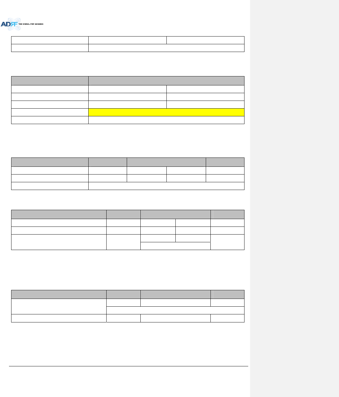
AdvancedRFTechnologies,Inc. 62
Totalinputperband10.0dBm10.0dBm
HETotalInput13.0dBm
TheRFUcannowbecommissionedwiththe10dBofattenuationbyusingaDLinputcommissionlevelof
18dBm.
Table7‐6HEmaximumdownlinkinputlevelafteradding10dBattenuatortoHEdownlinkinputport
WSPAT&T
Totalinputperband10.0dBm10.0dBm
Backoffperbandforbreathing5.0dB5.0dB
EstimatedTotalMaxInputperband15.0dBm15.0dBm
EstimatedTotalMaxInput18.0dBm
AvailableMaxInput25.0dBm
7.2.2.1.2.3 MultipleWSPs’signalsexistinthePCSband(withpowerratio)
Table7‐7displaysallthevariousincomingDLsignalsthatareenteringintotheHEPCSBCU.TheADX‐H‐BCU
hastotal3inputportsandintheexamplebeloweachporthasbeenassignedtoSprint,AT&T,andVzW.
Table7‐7Inputsignalconditions@HEBCUdownlinkinput
WSPSprint‐CH1AT&T‐CH2VzW‐CH3
TechnologyCDMAGSMWCDMACDMA
Totalinputperband5.0dBm10.0dBm10.0dBm7.0dBm
BCUTotalInput14.5dBm
CalculatemaximumDLinputlevelforeachWSPfactoringintheback‐offvalues.
Table7‐8HEmaximumdownlinkinputlevel
WSPSprint‐CH1AT&T‐CH2VZW‐CH3
Totalinputpercarrier5.0dBm10.0dBm10.0dBm7.0dBm
Backoffperbandforbreathing4.0dB5.0dB5.0dB4.0dB
EstimatedTotalMaxInputpercarrier9.0dBm
15.0dBm15.0dBm
11.0dBm
18.0dBm
BasedonthecalculatedmaximumDLinputlevelforeachport,theusershoulddecideonatargetmaximum
InputpowerforeachBCUport.
‐ TargetedmaximumInputpowerforeachBCUportshouldnotbelessthanthecalculated
maximumDLinputlevelforeachportandshouldnotexceedthemaximuminputlevel,25dBm.
Table7‐9Targetedmaximuminputpower
WSPSprint‐CH1AT&T‐CH2VZW‐CH3
Targetedmaximuminputpower
9.0dBm18.0dBm11.0dBm
19.2dBm
TargetedDLOutputPowerRatiosetbyuser30.0%20.0%50.0%
CalculatetheDLmaximumoutputpowerofBCUbasedontargetedmaximumInputpowerforeachBCUport.
‐ ThehighestpowerratiothathasbeensetisVZW‐ CH3@50%.TheADX‐H‐BCUwillapply
attenuationtothisporttosetthemaximumoutputpowerto5dBm,therefore6dBof
attenuationwillbeappliedtothisport.
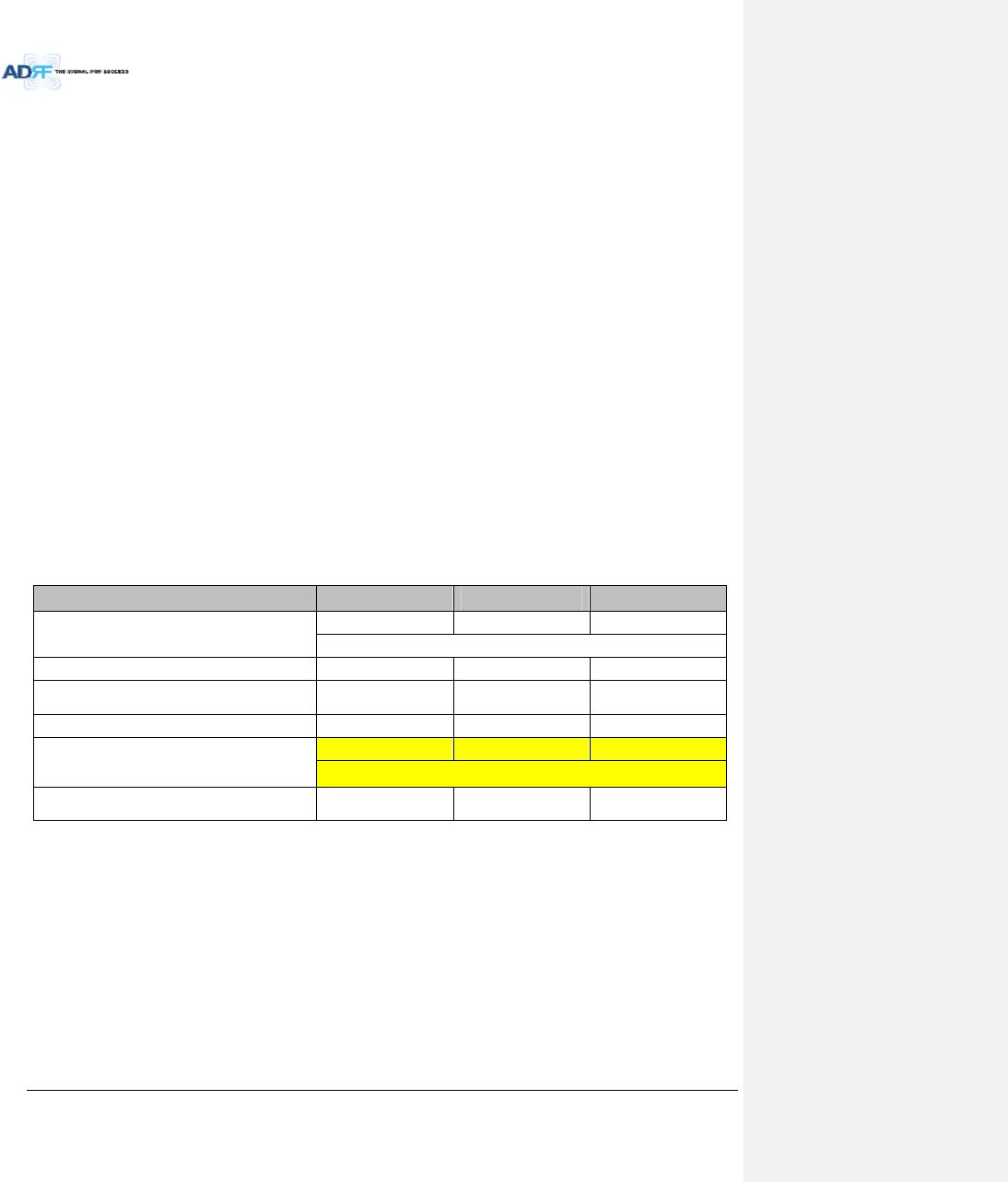
AdvancedRFTechnologies,Inc. 63
‐ TheattenuationandDLoutputALClevelfortheotherportsaresetbasedontheformulabelow
tokeepthepowerratiobetweenBCUports.
Themaximumoutputpowerforthespecifiedpath=10*log10[10^(Max_ALC/10)x(Pwr_Ratio)/
Max_Ratio]
Max_ALC:DLoutputALClevelforthepathwithmaximumpowerratio=5dBm
Pwr_Ratio:TargetedDLoutputpowerratiovalueforthespecifiedpath
Max_Ratio:maximumpowerratiovalue
Theattenuationforthespecifiedpath=Thetargetedmaximuminputpowerforthespecifiedpath‐
Themaximumoutputpowerforthespecifiedpath
DLoutputALClevel=Thetargetedmaximuminputpowerforthespecifiedpath‐Theattenuation
forthespecifiedpath
ThepathforAT&T‐CH2
Themaximumoutputpower=10*log10[10^(5/10)x20%/50%]=1.02dBm
TheATTvalue=18.0dBm‐1.02dBm=16.98dB16.5dB(thecontrolstepofusedattenuatoris
0.5dB)
DLoutputALClevel=18dBm–16.5dB=1.5dBm
ThepathforSprint‐CH1
Themaximumoutputpower=10*log10[10^(5/10)x30%/50%]=2.78dBm
TheATTvalue=9.0dBm‐2.78dBm=6.22dB6.0dB(thecontrolstepofusedattenuatoris0.5dB)
DLoutputALClevel=9.0dBm–6.0dB=3.0dBm
‐ TheDLmaximumoutputpowerofBCUisthesumofmaximumoutputpowerforeachportand
thispowerbecomestheHERFUinputcommissioninglevel.
‐ ThemaximuminputlevelofHERFUshouldbelessthan10dBm(=5dBm+10*log10(3))because
themaximumoutputofBCUpereachpathdoesn’texceed5dBmbyALCfunction.
Table7‐10MaximumOutputPowerpercarrier
WSPSprintAT&TVZW
Targetedmaximuminputpower
9.0dBm18.0dBm11.0dBm
19.2dBm
TargetedDLOutputPowerRatiosetbyuser30.0%20.0%50.0%
DLmaximumoutputpower
(ATTcontrolstep,0.5dBisnotconsidered)2.78dBm1.02dBm5.0dBm
ATTvalue6.0dB16.5dB6.0dB
DLoutputALClevelor
DLMaximumoutputpower
(ATTcontrolstep,0.5dBisconsidered)
3.0dBm1.5dBm5.0dBm
8.2dBm(RFUDLInputcommissioninglevel)
DLOutputPowerRatio
consideringATTcontrolstep0.5dB30.37%21.50%48.13%
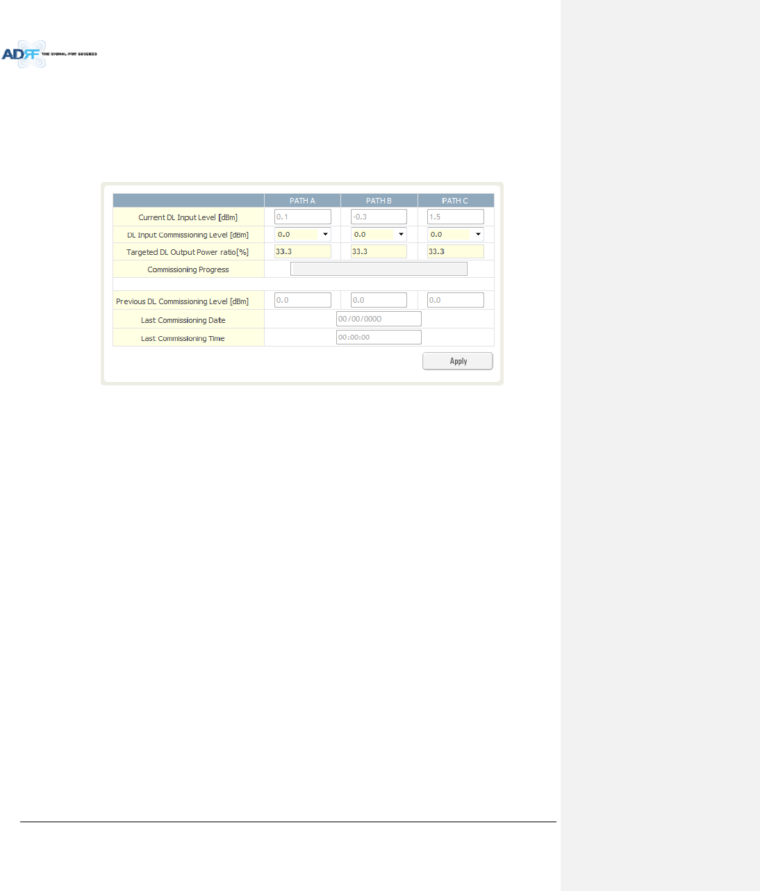
AdvancedRFTechnologies,Inc. 64
7.2.2.1.3 HEBCUCommissioning
WhenperformingBCUcommissioning,theuserwillneedtoentertheDLinputcommissioningleveland
TargetedDLOutputPowerRatioforeachRFpath.Refertosection7.2.2.1tocalculateDLinputcommissioning
level.Ifaportisnotbeingused,theDLInputCommissioningLevelshouldbesetto“disabled”.
7.2.2.1.3.1 HEBCUCommissioningProcedure
GotoInstallpageoftheBCUontheWeb‐GUI
Figure7‐6BCUInstallWindow
SelectaDLInputCommissioningLevelforeachRFpath
‐ DLInputCommissioningLevelsrangeis0~+25dBm(0.5dBstep)
EnterHEBCUdownlinkoutputpowerratioforeachport
Pressthe“Apply”button
TheattenuationvalueandoutputALClevelforeachDL/ULpathwillbesetautomaticallybasedontheHEBCU
downlinkinputcommissioninglevelanddownlinkoutputpowerratioforeachport.
TheBCUwillchecktoseeifALCisactiveonanyoftheports.
‐ Duringthecommissioningroutine,ifALCisactivated,apopupmessagewillappearstatingthat
ALCisrunning.Ifthisisthecase,thenthereisachancethatthe“back‐off”valueneedstobe
increasetoallowmorebreathingroom.
TheBCUcheckstoseeiftheBCUhasanyalarms.
‐ Ifasoftfailispresent,thesystemwillprompttheuserwhetherornottheywouldliketo
continue.
‐ Ifhardfailispresent,thecommissioningprocesswillstopimmediately.
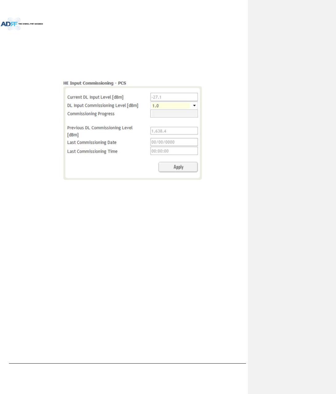
AdvancedRFTechnologies,Inc. 65
7.2.2.1.4 HERFUcommissioning
IfaBCUisbeingusedinthesystem,theBCUshouldbecommissionedbeforecommissioningtheHERFU.
ForRFUcommissioning,theuserwillneedtocalculatetheDLinputcommissioninglevel.Refertosection
7.2.2.1toforinformationtodeterminetheDLinputcommissioninglevel.
7.2.2.1.4.1 HERFUcommissioningProcedure
GotoInstallpageofRFUontheWeb‐GUI
Figure7‐7RFUInstallWindow
EnterHERFUdownlinkinputcommissioninglevel
‐ Inputrange:0~+25dBm,0.5dBstep
Pressthe“Apply”button
TheattenuationlevelswillbesetautomaticallybasedonDLInputCommissioningLevelthatisselected.
CheckstoseeifDLinputislow.
‐ Duringthecommissioningroutine,ifDLinputlevelis10dBlessthancommissioninglevel,a
popupmessagewillappearstatingthatDLinputislow.Ifthisisthecase,thenthereisachance
thatthe“back‐off”valueneedstodecreasebreathingroom.
CheckstoseeifALCisactive.
‐ Duringthecommissioningroutine,ifALCisactivated,apopupmessagewillappearstatingthat
ALCisrunning.Ifthisisthecase,thenthereisachancethatthe“back‐off”valueneedstobe
increasetoallowmorebreathingroom.
CheckstoseeiftheRFUhasanyalarms.
‐ Ifasoftfailispresent,thesystemwillprompttheuserwhetherornottheywouldliketo
continue.
‐ Ifhardfailispresent,thecommissioningprocesswillstopimmediately.
Commissioningissuccessfullycompleted.
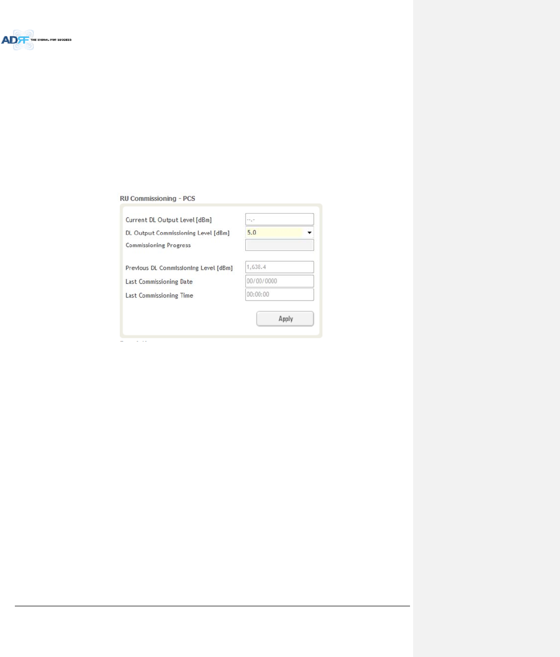
AdvancedRFTechnologies,Inc. 66
7.2.3 HPRCommissioning
HPRcompositedownlinkoutputlevelcanbedeterminedusingsimulationtoolslikeiBwave.Usershould
simulatethisoutputlevelinordertoensurethatallserviceareashavesufficientcoverage.
ThesimulatedcompositeDLoutputpowervalueshouldnotexceedthemaximumoutputleveloftheHPR,
whichis46/44.8/43dBm.
ThesimulatedcompositeDLoutputpowervaluewouldbeusedasHPRDLcommissioningoutputlevel.DL
attenuationvaluewillbeadjustedautomaticallybasedonthissimulatedvalueHPRcommissioninglevel.
ForHPRcommissioning,usershouldenterinformationonDLoutputcommissioninglevel.Refertosection
7.2.2.1tocalculateDLoutputcommissioninglevel.
GotoInstallpageofRemoteModuleonthewebGUI
Figure7‐8RemoteModuleInstallWindow
EnterHPRdownlinkoutputcommissioninglevel
‐ Outputrange:5~+46/44.8/43dBm,0.5dBstep
Pressthe“Apply”button
TheattenuationlevelforeachDL/ULpathwillbesetautomaticallybasedonDLOutputCommissioningLevel
thatisentered
CheckstoseeifDLoutputislow.
‐ Duringthecommissioningroutine,ifDLoutputlevelis10dBlessthancommissioninglevel,a
popupmessagewillappearstatingthatDLoutputislow.Ifthisisthecase,thenthereisachance
thatthe“back‐off”valueneedstodecreasebreathingroom.
CheckstoseeifALCisisactive.
‐ Duringthecommissioningroutine,ifALCisactivated,apopupmessagewillappearstatingthat
ALCisrunning.Ifthisisthecase,thenthereisachancethatthe“back‐off”valueneedstobe
increasetoallowmorebreathingroom.
CheckstoseeiftheSub‐RUhasanyalarms.
‐ Ifasoftfailispresent,thesystemwillprompttheuserwhetherornottheywouldliketo
continue.
‐ Ifhardfailispresent,thecommissioningprocesswillstopimmediately.
Commissioningissuccessfullycompleted.

AdvancedRFTechnologies,Inc. 67
7.3 DASInstallVerification
7.3.1 SettingSNMP&RemoteIP
GotoInstallpageofNMS(refertosection8.2.4.1.4)
Whenexternalmodemboxisconnected,usershouldsetSNMP&RemoteIPinformation.
7.3.2 VerificationthroughWebbasedGUI
GotoSysteminformationpageofSystem(refertosection8.2.5.4.1)
‐ CheckifRemoteModulewithsamefrequencybandexistmorethanonewithinoneHPR.
‐ CheckifthereareanynoncommissionedmodulesinHEorRU.
‐ Checkifanycriticalalarmsarepresent.
7.3.3 ULnoisepowerdetection
WhentheULnoiselevelsislargerthantheexpectedvalue,ADXDAShasafunctionthatwillmeasurethe
uplinknoiseforeachHPRandwillgeneratesareportwiththeULnoiselevels.Thiswillhelptheuserdetermine
whichHPRmightbethecauseoftheelevatedULnoise.
ULnoisepowermeasurementcanbeperformedforonlyonefrequencybandatatime.
Formoreinformation,refertosection8.2.3.3.3.
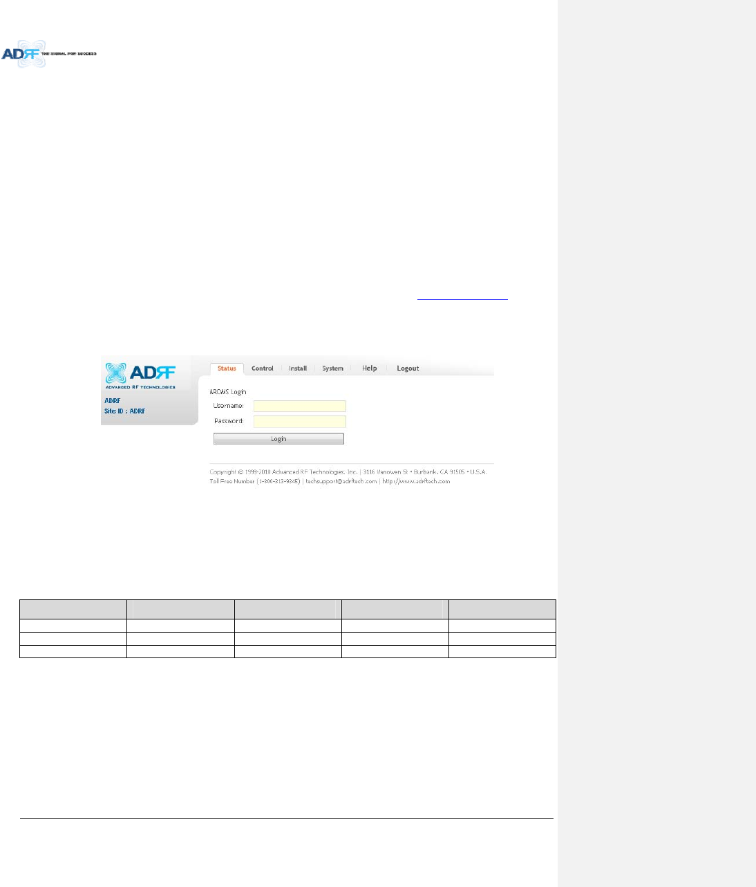
AdvancedRFTechnologies,Inc. 68
8. WEB‐GUI
8.1 Web‐GUISetup
TheWeb‐GUIallowstheusertocommunicatewiththeDASsystemeitherlocallyorremotely.Toconnectto
theDASsystemlocally,youwillneedalaptopwithanEthernetportandaRJ‐45crossovercable.Toconnectto
theDASsystemremotely,youwillneedtohaveanactiveinternetconnectionandtheADXsystemmusthaveand
externalmodemboxconnectedtotheADX.
8.1.1 DASsystem/PCConnectionUsingWeb‐GUI
VerifythatyourLocalAreaConnectionissettoObtainanIPaddressautomaticallyundertheInternetProtocol
(TCP/IP)properties
‐ Ifyouareconnectingtotheunitremotely(useofamodem),thenskipthisandnextstep.
ConnecttheRJ‐45crossovercablebetweenthelaptop’sEthernetportandtherepeater’sEthernetport
LaunchanInternetBrowser
TypethefollowingIPaddressintotheaddressbarofMicrosoftInternetExplorer:http://192.168.63.1
‐ Ifyouareconnectingtotheunitremotely,thentypetheIPaddressofthemodemtoconnectto
theunit
Thefollowingloginscreenwillappear:
Figure8‐1Loginscreen
IfyouarenottheAdministrator,pleasetypeinyourassignedusername&passwordwhichyoushouldhave
receivedfromtheAdministrator.
Table8‐1AccountInformationforLogin
AccounttypeShowitemsControlItemsDefaultIDDefaultPassword
AdministratorallItems allitems admin admin
Userrestricteditemsrestricteditems adrf adrf
Guestrestricteditemsread‐only guest guest
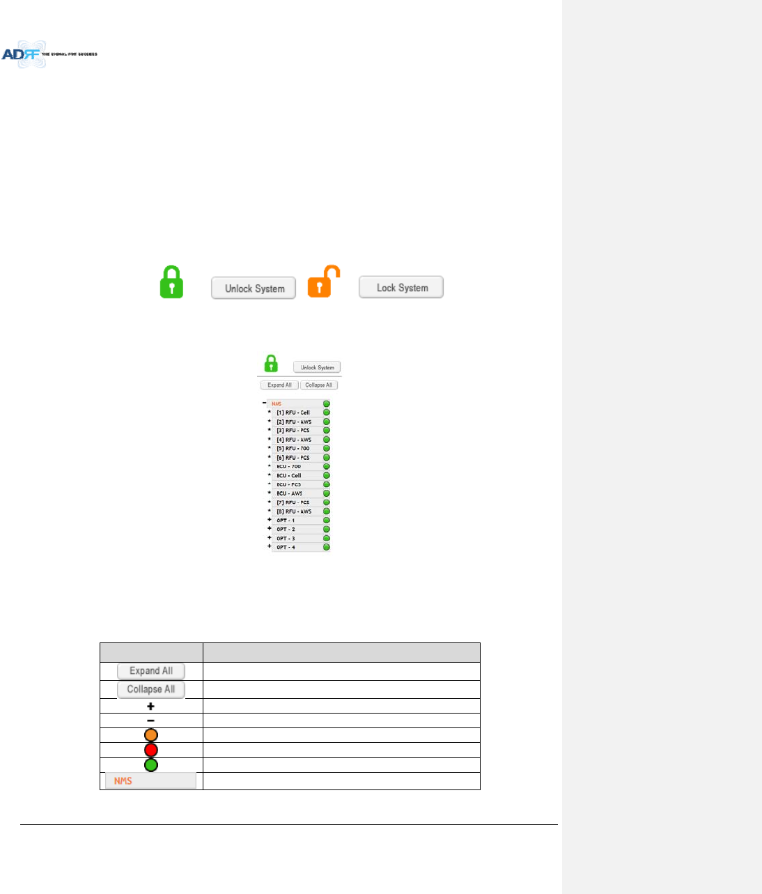
AdvancedRFTechnologies,Inc. 69
8.2 Administrator/UserMode
8.2.1 Common
8.2.1.1 NavigationtreeLock/Unlock
Whenthesystemis“Locked”,agreenlockiconwillappearabovethenavigationtree.Whenthesystemis
locked,newdevicescannotbeadded.Anydevicesaddedtothesystemwhenthesystemis“Locked”willnotbe
detectedbytheNMS.Afterasystemhasbeencommissionedproperly,thesystemshouldbeleftinthe“Locked”
position.Tounlockthesystem,clickonthe“UnlockSystem”buttontotherightoftheicon.
Whenthesystemis“Unlocked”,anorangeiconwillappearabovethenavigationtree.Whenthesystemis
unlocked,newdevicesaddedtothesystemwillbeautomaticallydetected.Oncethenewhardwareappearsinthe
systemtree,thenthesystemcanbelocked.Tolockthesystem,clickonthe“LockSystem”buttontotherightof
theicon.
Figure8‐2NavigationtreeLock/Unlock
8.2.1.2 NavigationTree
Figure8‐3Navigationtree
ThenavigationtreelocatedonthelefthandsideoftheWeb‐GUIallowstheusertoswitchbetweenthe
variousmodulesthatareconnectedtothesystem.
Table8‐2Navigationtree
ParametersDescription
Expandstheentirenavigationtree
Collapsestheentirenavigationtree
Themodulehastheexpandablesubordinatemodules
Thebranchiscurrentlyexpanded
Themodulehassoftfailalarm
Themodulehashardfailalarm
Themodulehasnoalarms(normal)
Theselectedmodulewillhaveorangecoloredtext
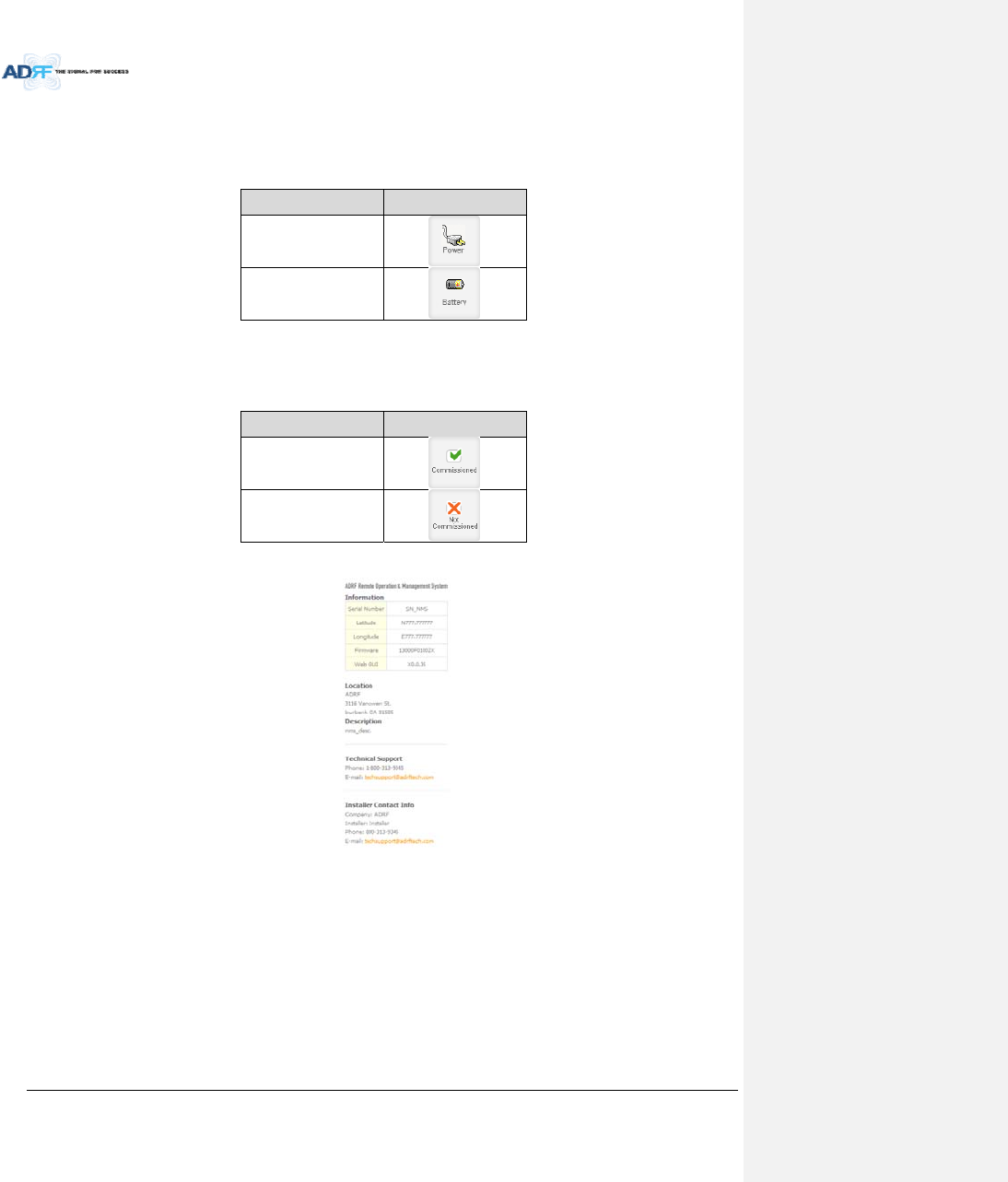
AdvancedRFTechnologies,Inc. 70
8.2.1.3 PowerStatus
Displaythepowersourcethatiscurrentlybeingused.
Table8‐3PowerSupplyStatus
InputPowerStatusDisplayImage
AC
Battery
8.2.1.4 CommissioningStatus
Displaywhetherornotthemodulehassuccessfullybeencommissioned.
Table8‐4CommissioningICON
StatusDisplayImage
Commissioned
Not‐Commissioned
8.2.1.5 Information
Figure8‐4ADXDASGeneralInformation
Information:Displaystheserialnumber,latitude/longitude,firmwareversionofselectedmodule,andWeb
GUIversionoftheNMS.
Location:DisplaystheaddresswheretheADXDASisinstalled.
Description:Displaysthedescriptionofselectedmodule.Thedescriptionofeachmodulecanbeeditedfrom
theInstalltab.Itisrecommendedtousethelocationofthemoduleasthedescription.Thisdescription
informationcanbeseenwhenhoveringoverthedevicetreeinordertoeasilyidentifyeachcomponent.
TechnicalSupport:DisplaysADRF’sTechnicalSupportcontactinformation.
InstallerContactInfo:Displaysthecontactinformationoftheinstaller.
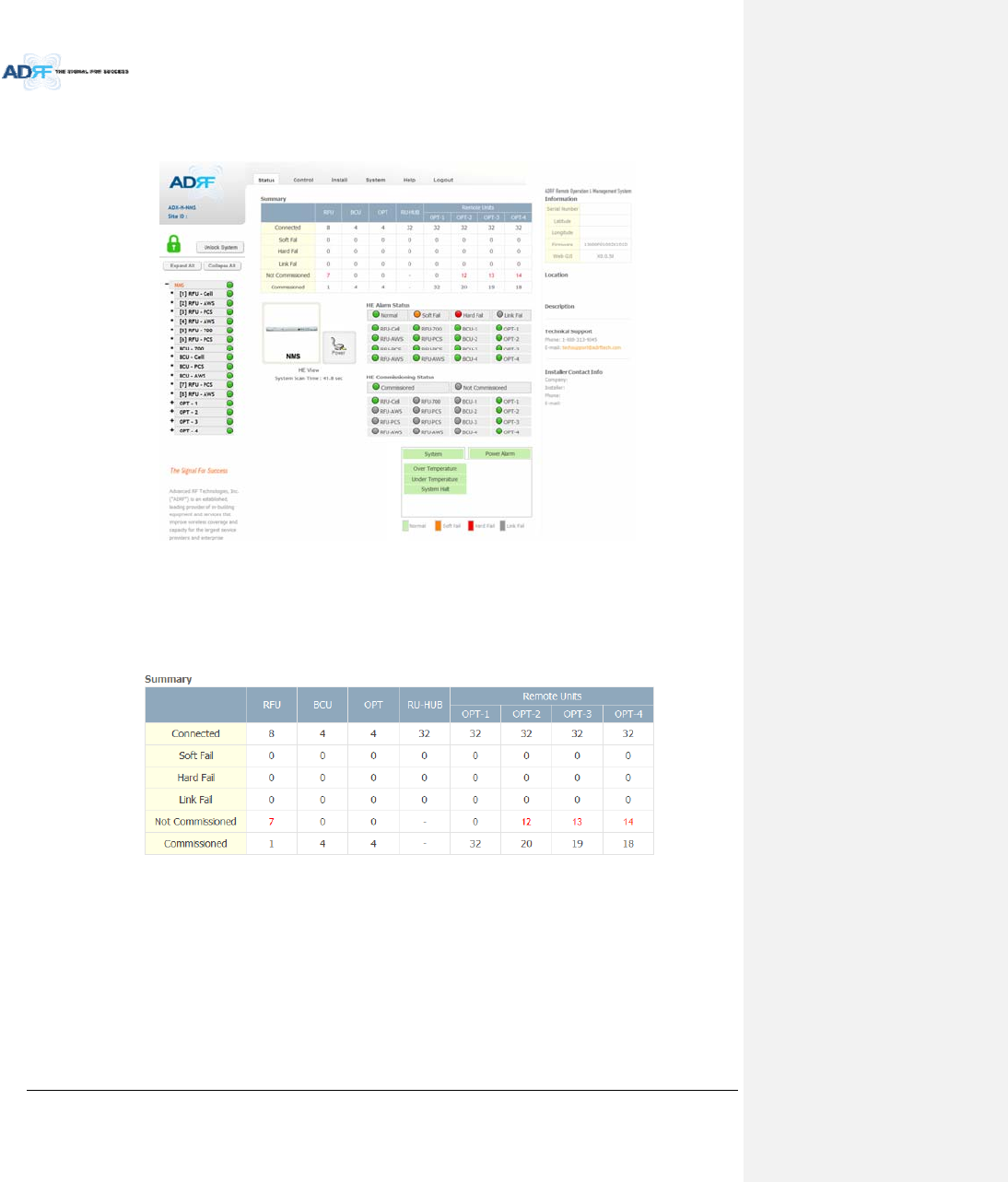
AdvancedRFTechnologies,Inc. 71
8.2.2 StatusTab
8.2.2.1 Status–NMS
Figure8‐5Status‐NMS
TheNMSStatuspageprovidesanoverallviewofhowthesystemisperforming.FromtheNMSStatuspage,
theusercanseewhatmodulesareconnectedtoADXDAS.Inaddition,theusercanseeifanyalarmsarepresent
inthesystemandalsothecommissioningstatusofeachmodule.
8.2.2.1.1 SystemSummary
Figure8‐6SystemSummary
TheSummarysectionprovidestheuserwiththenumberofcomponentsphysicallyconnected,thenumberof
soft/hard/linkfailspresentinthesystem,andalsothenumberofcommissionedandnon‐commissioned
componnets.
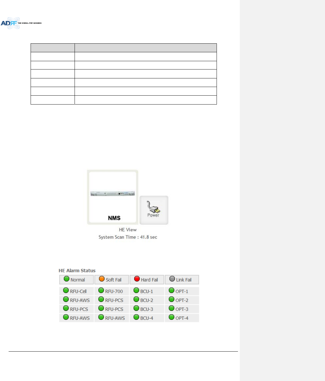
AdvancedRFTechnologies,Inc. 72
Table8‐5SystemSummaryDescription
ParametersDescription
ConnectedDisplaythenumberofmodulesphysicallyconnectedtoADXDAS
SoftFailDisplaythenumberofsoftfailpresentoneachmodule
HardFailDisplaythenumberofhardfailpresentoneachmodule
LinkFailDisplaythenumberoflinkfailpresentoneachmodule
NotCommissionedDisplaythenumberofnon‐commissionedorcommissionfailedmodule
CommissionedDisplaythenumberofsuccessfullycommissionedmodule
8.2.2.1.2 HEView/HPRView,SystemScanTime
HEView/RUView
‐ DisplayswhethertheNMSissettoHEvieworHPRview.
‐ Refertosection3.1.1.4
SystemScanTime
‐ Displaysthetimeittakestoscanandupdatetheinformationofallthemodulesthatareonthe
navigationtree.Thistimewillincreaseasmorecomponentsareaddedtothesystem.
‐ WhenNavigationTreeisunlocked,theusershouldwaitatleastthe“SystemScanTime”forthe
systemtodetectnewlyaddedhardware.
Figure8‐7Systemscantime,HEview/RUview
8.2.2.1.3 HEAlarmStatus
DisplaythealarmstatusofeachHEcomponent.
Figure8‐8HEalarmstatus
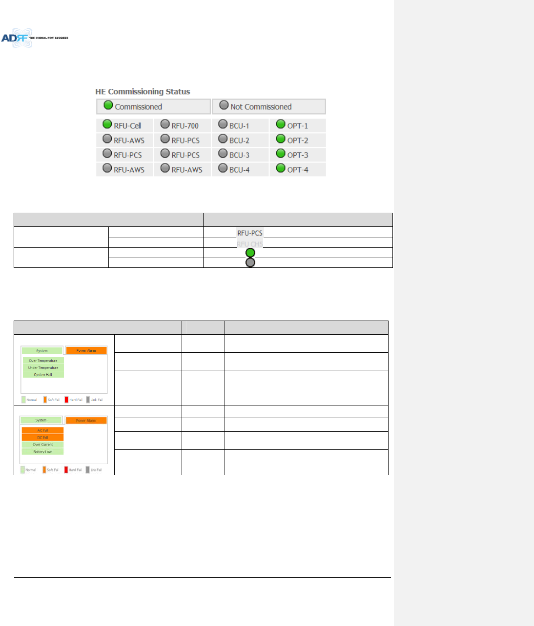
AdvancedRFTechnologies,Inc. 73
8.2.2.1.4 HECommissioningStatus
DisplaycommissioningstatusofeachHEcomponent.
Figure8‐9HECommissioningstatus
Table8‐6DescriptionforHECommissioningstatus
StatusDisplayDescription
InstalledStatusPhysicallyInstalledTextisblack
PhysicallyNot‐InstalledTextisgray
CommissioningStatusSuccessGreen
FailedornotcommissionedGray
8.2.2.1.5 Alarm
DisplaysalarmstatusoftheNMS.Ifanalarmispresentinthesystem,thecolorofthesystemalarmtabwill
changeaccordingtothetypeoffailure.
Table8‐7DescriptionforNMSalarm
AlarmSeverityDescription
System
OverTemperatureHardFail/
SoftFail
TemperatureofNMSishigherthanthethreshold
levelforovertemperaturealarm
UnderTemperatureSoftFailTemperatureoftheNMSislowerthanthethreshold
levelforundertemperaturealarm
SystemHaltHardFailHEsystemhalt
PowerAlarm
ACFailSoftFailACpowerisoperatingoutsideofitsnormalrange
DCFailSoftFailDCpowerisoperatingoutsideofitsnormalrange
OverCurrentHardFailTotalcurrentofHEishigherthanthethresholdlevel
forovercurrentalarm
BatteryLowSoftFailVoltageofbatteryconnectedtoHEPSUislowerthan
thedefinedthreshold
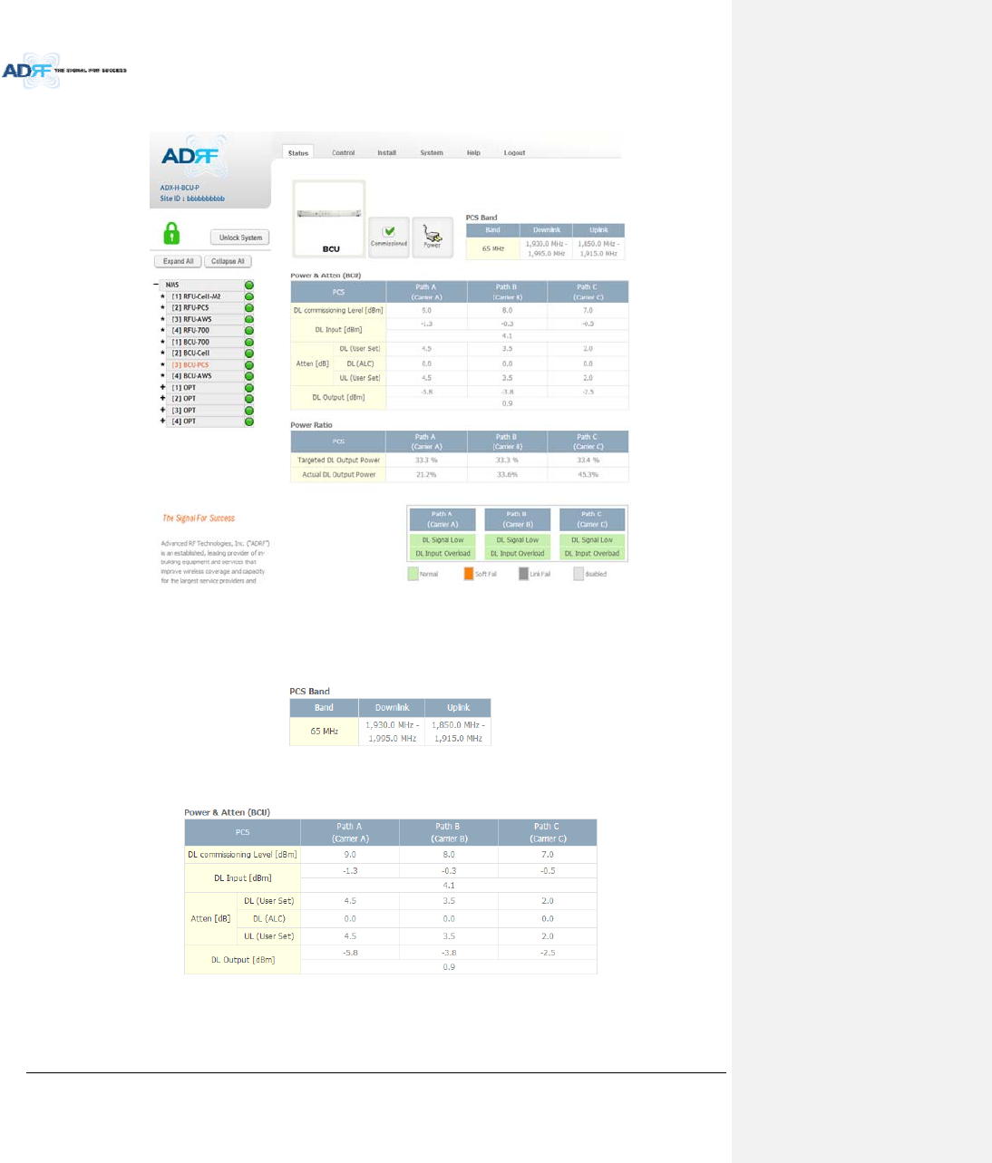
AdvancedRFTechnologies,Inc. 74
8.2.2.2 Status–BCU
Figure8‐10Status–BCU
8.2.2.2.1 Band
DisplaysthebandwidthandthefrequencyrangesforDLandULoftheBCUmodule.
Figure8‐11Status–BCUBand
8.2.2.2.2 Power&Atten
Figure8‐12Status–BCUPower&Atten
DLCommissioningLevel:DisplaysthecommissioninglevelforeachindividualRFpath.Ifunithasnot
beencommissioned,“NotCommissioned”willbedisplayed.
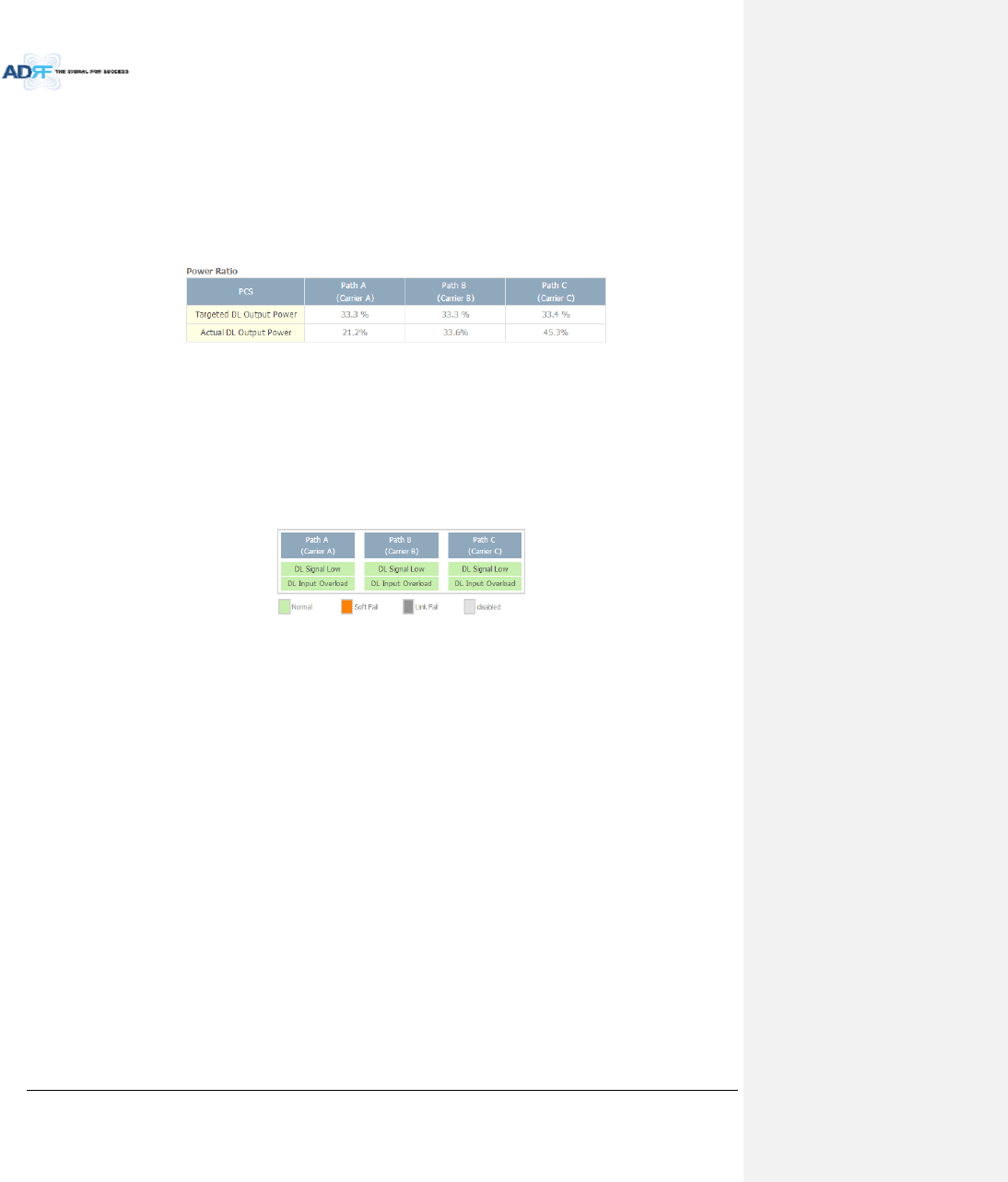
AdvancedRFTechnologies,Inc. 75
DLInput:DisplaysthecurrentlyincomingsignalstrengthofeachRFpathalongwiththecompositeDL
inputpowerofall3RFpaths.
Atten:Displaystheattenuationvaluesthatthesystemiscurrentlyusingwhichisdefinedbythe
powerratiosspecifiedbytheuser.
DLOutput:DisplaystheoutputvalueforeachRFpathalongwiththecompositeDLoutputpowerof
all3RFpaths.TheDLOutputlevelforeachRFpathwillnotexceed5dBmandthecompositeoutput
powerwillnotexceed10dBm.
8.2.2.2.3 PowerRatio
Figure8‐13Status–BCUPowerRatio
TargetedDLOutputPower:Displaysdesiredpowerratiosspecifiedbytheuser.Ifunithasnotbeen
commissioned,“NotCommissioned”willbedisplayed.
ActualDLOutputPower:Displaysthecurrentlypowerratiosthatthesystemisusing.Thesevalues
willfluctuatebasedontheamountoftrafficthatisinthesystem.
8.2.2.2.4 Alarm
DisplaysthecurrentalarmstatusofeachindividualRFpath.ParametersforbothDLSignalLowandDLInput
OverloadcanbespecifiedfromtheControltab.
Figure8‐14Status–BCUAlarm
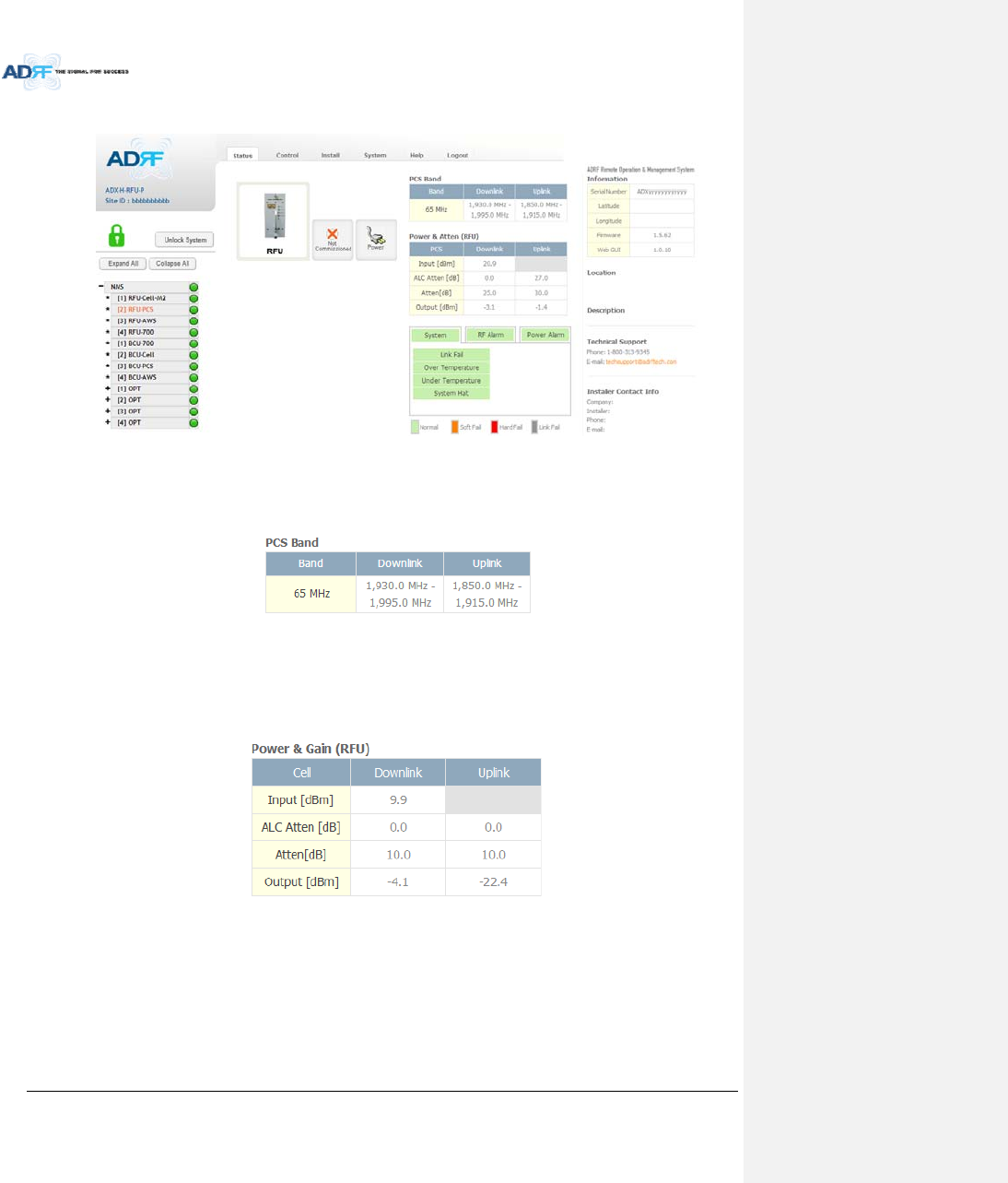
AdvancedRFTechnologies,Inc. 76
8.2.2.3 Status–RFU
Figure8‐15Status–RFU
8.2.2.3.1 Band
DisplaysthebandwidthandthefrequencyrangesforDLandULoftheRFUmodule.
Figure8‐16Status–RFUBand
8.2.2.3.2 Power&Gain(Admin/User)
AdminMode‐ DisplaystheDownlinkInput/output,Downlink/UplinkAttenuation,andUplink
Output.
UserMode‐DisplaystheDownlinkInput,Downlink/UplinkAttenuation,andUplinkOutput.
Figure8‐17Power&GainDisplay(Admin)
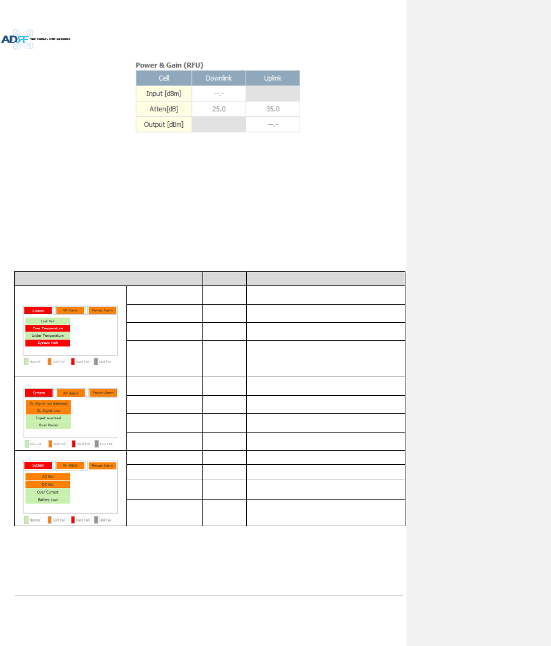
AdvancedRFTechnologies,Inc. 77
Figure8‐18Power&GainDisplay(User)
Input[dBm]:DisplaystheDownlinkRFinputlevelwhichcomesfromtheADX‐H‐BCUorBTS.Thisvalueshould
bebetween0to25dBm.
ALCAtten[dB]:TheamountofattenuationthatisbeingusedbythesystemwhenALCisactive.
Atten[dB]:Theamountofattenuationthathasbeensetmanuallybytheuser.
Output[dBm]:Thedownlink/uplinkoutputpoweroftheRFUandNOTtheoutputpoweroftheRU.
8.2.2.3.3 Alarm
DisplaysSystem,RF,andPowerAlarms.Ifanalarmispresentinthesystem,thenthecolorofthetabwill
changeaccordingtothetypeoffailure.
Table8‐8RFUAlarmStatus
AlarmSeverityDescription
System
LinkFailSoftFailAcomponentisphysicallyconnected,butthe
NMSisunabletocommunicatewithit.
OverTemperatureHardFail/
SoftFail
ThetemperatureofNMSishigherthanthe
thresholdlevelforovertemperaturealarm.
UnderTemperatureSoftFailThetemperatureofNMSislowerthanthe
thresholdlevelforundertemperaturealarm.
SystemHaltHardFail
Systemwillgointoa“SystemHalt”statewhena
hardfailalarmdoesnotclearafter10checks.
SystemHaltcanonlybeclearedwithapower
cycle,reboot,orfactorysettings.
RFAlarm
DLSignalnotdetectedSoftFailDownlinkinputsignalislowerthanthedefined
thresholdbyuser.
DLSignalLowSoftFailDownlinkinputsignalislowerthanthedefined
thresholdbyuser.
InputOverloadHardFail/
SoftFail
Downlinkinputsignalishigherthanthedefined
threshold.
OverpowerHardFail/
SoftFail
Uplinkoutputsignalishigherthanthedefined
thresholdbyuser.
PowerAlarm
ACFailSoftFailACpowerisnotoperatingwithinparameters.
DCFailSoftFailDCpowerisnotoperatingwithinparameters.
OverCurrentHardFailTotalcurrentofHEishigherthanthethreshold
levelforovercurrentalarm.
BatteryLowSoftFailVoltageofbatteryconnectedtoHEPSUislower
thanthedefinedthreshold.
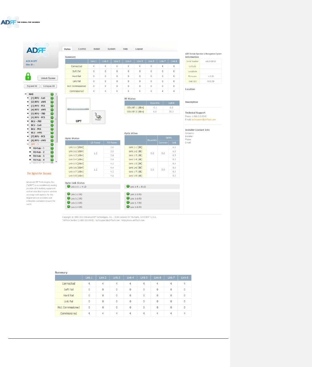
AdvancedRFTechnologies,Inc. 78
8.2.2.4 Status–ODU
Figure8‐19Status‐ODU
8.2.2.4.1 Summary
TheSummarysectiondisplaysthenumberofremotemodulesthatarephysicallyconnected,thenumberof
soft/hard/linkfailalarms,andthenumberofRemoteModulethathavebeencommissionedandthenumberof
RemoteModulethatneedtobecommissioned.
Figure8‐20Summary(Status–ODU)
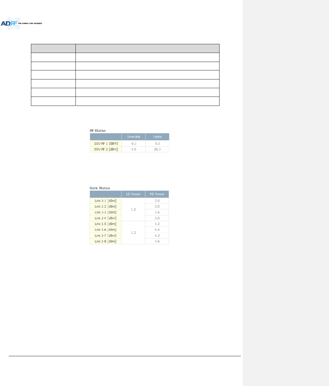
AdvancedRFTechnologies,Inc. 79
Table8‐9SummaryDescription
ParametersDescription
ConnectedDisplaysthenumberofRemoteModule’sconnectedtotheADX‐RACK‐ODU.
SoftFailDisplaysthetotalnumberofsoftfailpresent.
HardFailDisplaysthenumberofhardfailpresentoneachmodule.
LinkFailDisplaysthenumberoflinkfailpresentoneachmodule.
NotCommissionedDisplaysthenumberofnon‐commissionedorcommissionfailedmodule.
CommissionedDisplaythenumberofsuccessfullycommissionedmodule
8.2.2.4.2 RFStatus
DisplaystheDLinputpowerandtheULoutputpowerforeachODU.
AnADX‐RACK‐ODUiscomposedof2ODUs.
Figure8‐21RFStatus(Status–ODU)
8.2.2.4.3 OpticStatus
DisplayLDPowerandPDPowerforeachopticpath.LDPoweristhepowerthatisbeingsenttotheHPRand
PDPoweristhepowerthatisbeingreceivedfromtheRU.
Figure8‐22OpticStatus(Status–ODU)
8.2.2.4.4 OpticAtten(AdminOnly)
TheADX‐H‐ODUhas3typesofattenuators.
DownlinkCommonAttenuator‐DisplaysthecommonattenuationlevelontheDLpath.
UplinkCommonAttenuator‐DisplaysthecommonattenuationlevelontheULpath.
UplinkOpticAttenuator‐Displaystheamountofattenuationusedateachopticallink.
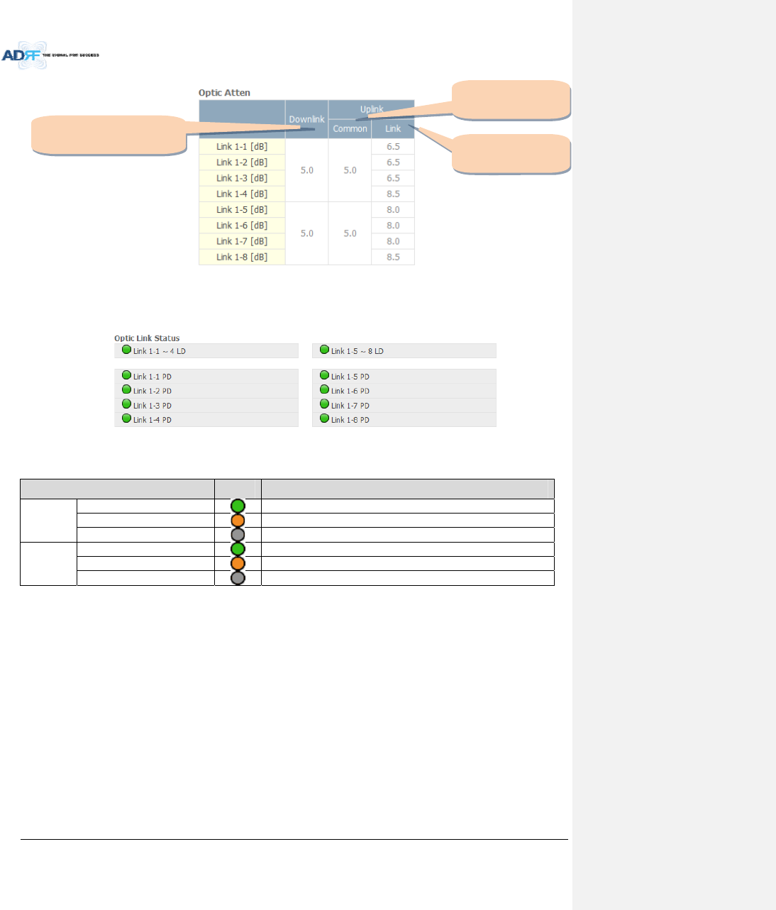
AdvancedRFTechnologies,Inc. 80
Figure8‐23OpticAttenuation(Status–ODU)
8.2.2.4.5 OpticPathStatus
Displaystheopticstatusforeachopticpath
Figure8‐24OpticPathStatus(Status–ODU)
Table8‐10Descriptionforopticpathstatus
StatusDisplayDescription
LDStatus
NormalGreen,opticsignalbeingsenttoMasterHPRis>‐5dBm
LDfailOrange,opticsignalbeingsenttoMasterHPRis<‐5dBm
NotConnectedGray,noconnectionbetweenODUandMasterRU
PDStatus
NormalGreen,opticsignalbeingreceivedfromMasterHPR is>‐10dBm
PDfailOrange,opticsignalbeingreceivedfromMasterHPR is<‐10dBm
CommFailorNotConnectedGray,noconnectionbetweenODU andMasterRU
Downlink
Commonattenuator
Uplink
Commonattenuator
Uplink
Opticattenuator
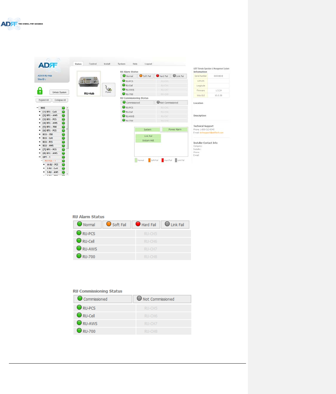
AdvancedRFTechnologies,Inc. 81
8.2.2.5 Status–RUHub
RU‐HubisnotseparatemodulebutisintegratedintothemasterRU.ThepictureofHPRHubdisplayedon
webbasedGUIissameasthepictureofmasterRU.
Figure8‐25Status‐RUHub
8.2.2.5.1 RUAlarmStatus
TheHPRHubcansupportupto8remotemodules.TheHPRalarmstatusdisplaysthealarmstatusofeach
remotemodule.
Figure8‐26RUAlarmStatus(Status‐HPRHub)
8.2.2.5.2 RUCommissioningStatus
DisplaytheCommissioningstatusofeachRemoteModule.
Figure8‐27RUCommissioningStatus(Status‐RUHub)
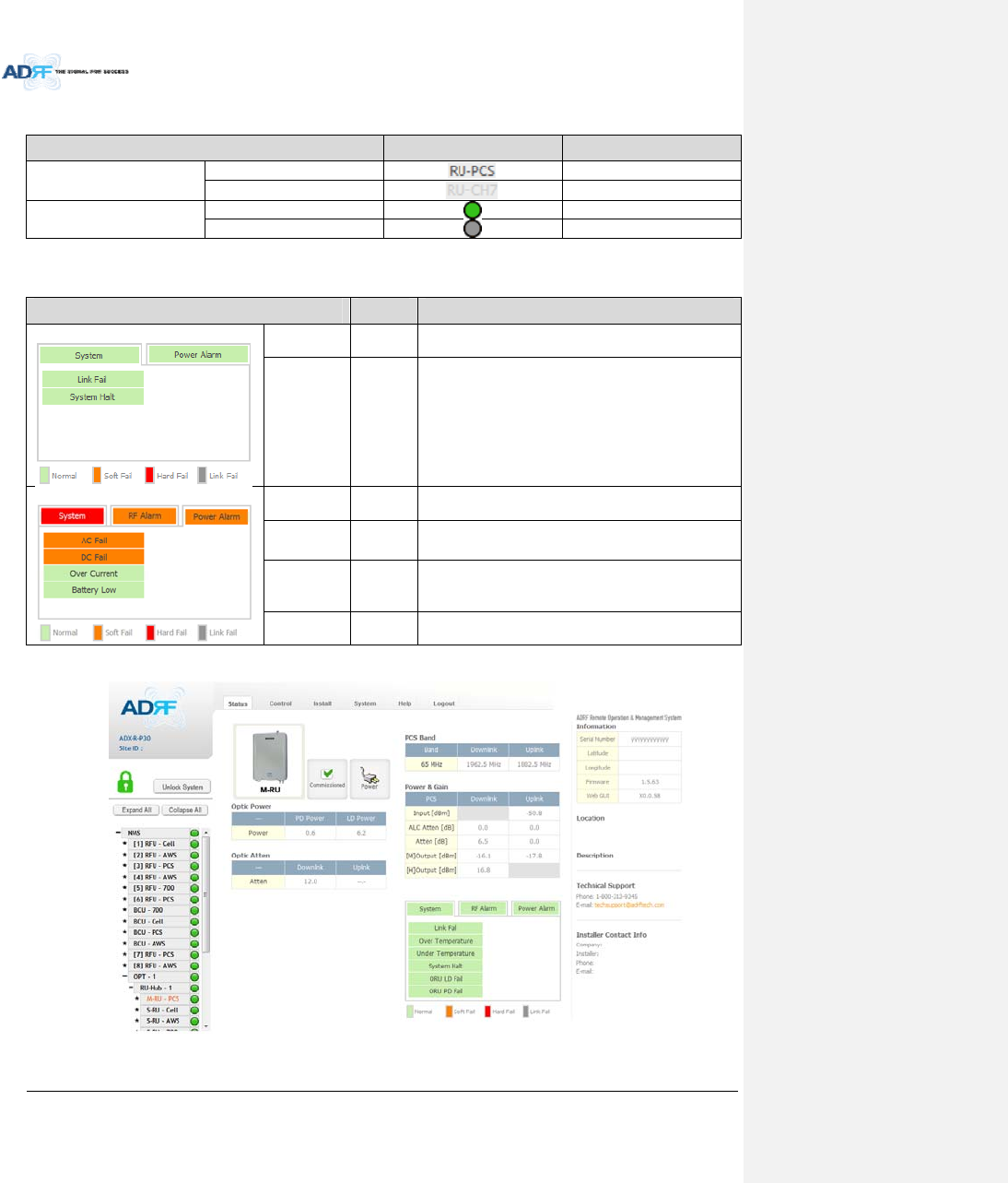
AdvancedRFTechnologies,Inc. 82
Table8‐11DescriptionforRUCommissioningstatus
StatusDisplayDescription
InstalledStatusInstalledTextisblack
Not‐InstalledTextisgray
CommissioningStatusSuccessGreen
FailornotyetGray
8.2.2.5.3 Alarm
Table8‐12AlarmStatus(Status‐RUHub)
AlarmSeverity Description
SystemLinkFailSoftFail Presentwhenamodulecannotcommunicatewiththe
NMS
SystemHaltHardFail
Systemwillgointoa“SystemHalt”statewhenahard
failalarmdoesnotclearafter10checks.SystemHalt
canonlybeclearedwithapowercycle,reboot,or
factorysettings.
PowerAlarmACFailSoftFail ACpowerisnotwithinparameters.
DCFailSoftFail DCpowerisnotwithinparameters.
OverCurrentHardFail TotalcurrentofHPRishigherthanthethresholdlevel
forovercurrentalarm
BatteryLowSoftFail VoltageofbatteryconnectedtoHPR PSUislowerthan
thedefinedthreshold
8.2.2.6 Status–Remotemodule
Figure8‐28Status–RemoteModule
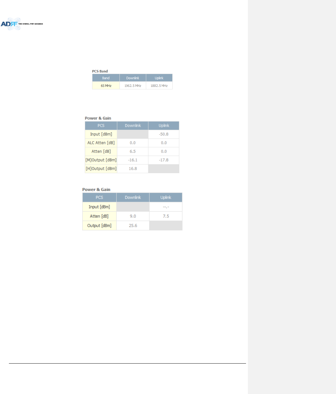
AdvancedRFTechnologies,Inc. 83
8.2.2.6.1 Band
Displaythespectrumthatisbeingused.Thebandcolumndisplaysthebandwidththathasbeenused.The
downlinkcolumndisplaysthecenterfrequencyoftheuseddownlinkband.Theuplinkcolumndisplaysthecenter
frequencyoftheuseduplinkband.
Figure8‐29PCSBandInformation(Status–RemoteModule)
8.2.2.6.2 Power&Gain(Admin/User)
DisplaytheDownlinkoutput,Downlink/UplinkAttenuation,andUplinkInput/output.
Figure8‐30Power&Gain(Admin)
Figure8‐31Power&Gain(User)
Admin
o Input[dBm]:DisplaystheRFinputlevelforUplinkonlyfortheRemoteModule.
o ALCAtten[dB]:TheamountofattenuationusedwhenALCisactivate.
o Atten[dB]:Theamountofattenuationmanuallysetbytheuser.
o [M]Output[dBm]:OutputpowerofRFtransceiver(1
st
stageamplification).
o [H]Output[dBm]:OutputpowerofdownlinkHPA(2
nd
stageamplification).
User
o Input[dBm]:DisplaystheRFinputlevelforUplinkonlyfortheRemoteModule.
o Atten[dB]:Theamountofattenuationmanuallysetbytheuser.
o Output[dBm]:Displaysthetotalcompositeoutputpower.
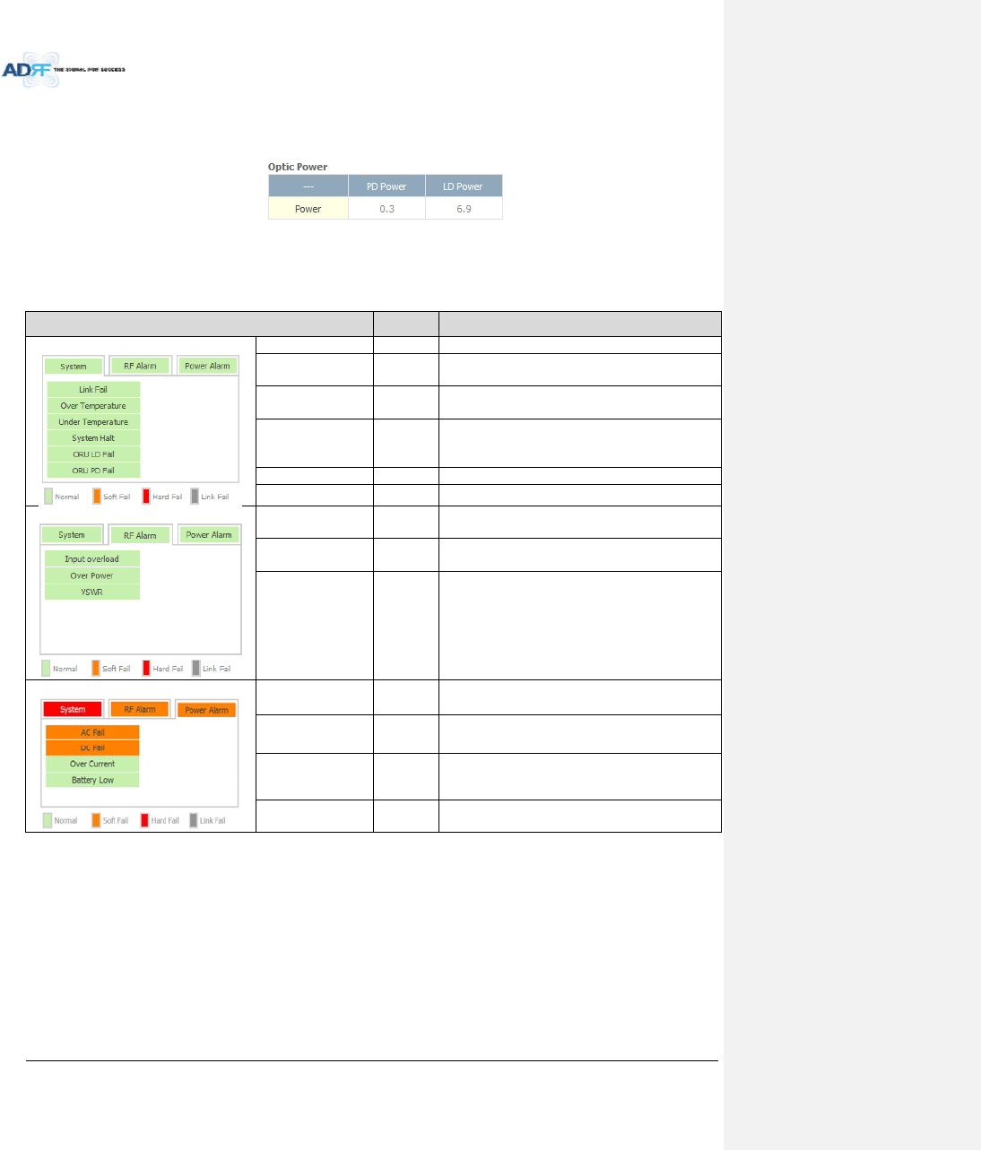
AdvancedRFTechnologies,Inc. 84
8.2.2.6.3 OpticPower(Master‐RUOnly)
DisplaytheLDPowerandPDPowerofopticmoduleinsidetheMasterRU.
Figure8‐32OpticPower(Status–MasterHPRonly)
8.2.2.6.4 OperatingStatus
Table8‐13OperatingStatus(Status–RemoteModule)
AlarmSeverity Description
SystemLinkFailSoftFail NocommunicationwithNMS.
OverTemperatureHardFail
/SoftFail
Temperatureishigherthanthethresholdlevelfor
overtemperaturealarm.
Under
TemperatureSoftFail Temperatureislowerthanthethresholdlevelfor
undertemperaturealarm.
SystemHaltHardFail
SystemhaltoneithertheMasterHPR orSlaveRU.
Systemhaltoccurswhenahardfailalarmfailsto
clearafter10checks.
ORULDFailSoftFail LDFailpresentintheMasterRU’sopticunit.
ORUPDFailSoftFail PDFailpresentintheMasterRU’sopticunit.
RFAlarmInputOverloadHardFail Uplinkinputsignalishigherthanthedefined
threshold.
OverPowerHardFail
/SoftFail
Downlinkoutputsignalishigherthanthedefined
thresholdbyuser.
VSWRSoftFail Triggeredwhenpowerisbeingreflectedbackto
thesystem,typicallyduetoalooseconnector.
PowerAlarmACFailSoftFail ACpowerisnotoperatingwithinparameters.
DCFailSoftFail DCpowerisnotoperatingwithinparameters.
OverCurrentHardFail TotalcurrentofHPRishigherthanthethreshold
levelforovercurrentalarm.
BatteryLowSoftFail VoltageofbatteryconnectedtoHEPSUislower
thanthedefinedthreshold.
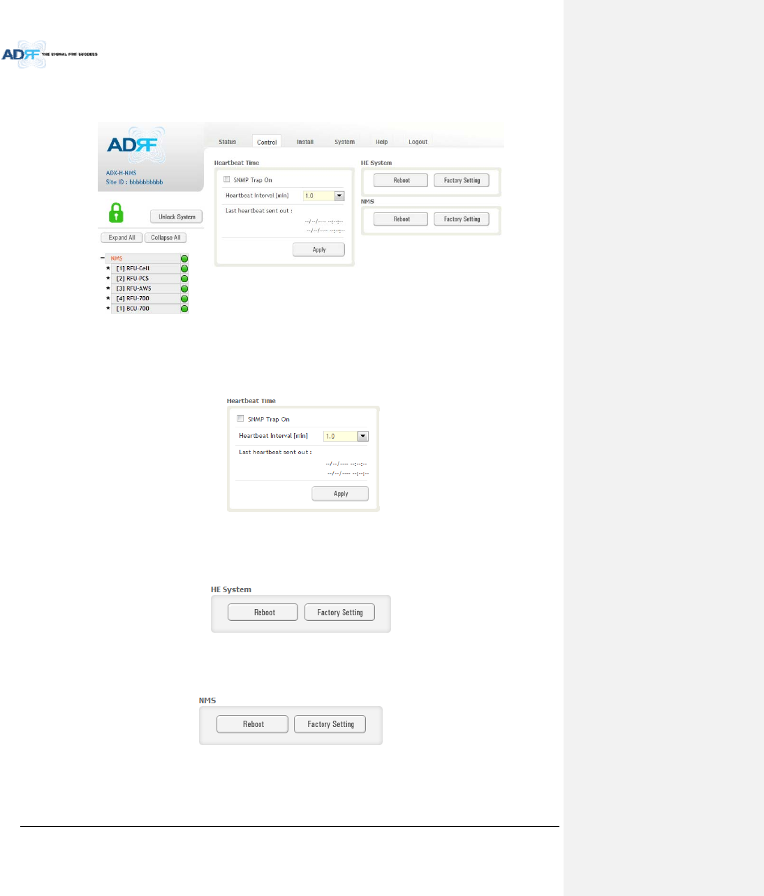
AdvancedRFTechnologies,Inc. 85
8.2.3 ControlTab
8.2.3.1 Control–NMS
Figure8‐33Control‐NMS
8.2.3.1.1 HeartbeatTime
AllowstheusertoenableordisableSNMPtrapsfrombeingsentoutandalsospecifytheHeartbeatinterval.
Timeanddatestampsofthelast2heartbeatswillbedisplayedinthe“Lastheartbeatsentout”section.
Figure8‐34Heartbeat(Control–NMS)
8.2.3.1.2 HESystem
AllowstheusertoperformaHEsystemrebootorHEfullsystemfactorysettings
Figure8‐35HESystemReboot&FactorySetting(Control–NMS)
8.2.3.1.3 NMSSystem
AllowstheusertoperformaNMSUnitrebootorNMSfactorysettings
Figure8‐36NMSSystemReboot&FactorySetting(Control–NMS)
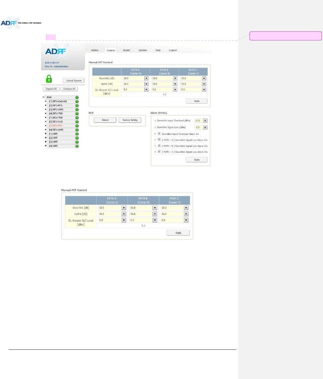
AdvancedRFTechnologies,Inc. 86
8.2.3.2 Control–BCU
Figure8‐37Control–BCU
8.2.3.2.1 ManualATTControl
Figure8‐38Control–BCUManualATTControl
Downlink:AllowstheusertomanuallyadjusttheDLattenuationlevelsforeachRFpath.Adjusting
thesesettingsisnotrecommendedsinceitwillchangethepowerratiossetbytheuser.
Uplink:AllowstheusertomanuallyadjusttheULattenuationlevelsforeachRFpath.Adjustingthese
settingsisnotrecommended,unlessadditionalattenuationisneededontheULpath.
DLOutputALCLevel:AllowstheusertomanuallysettheDLOutputALCLevelsforeachRFpath.
Adjustingthesesettingsisnotrecommendedsinceitwillchangethepowerratiossetbytheuser.
ThesesettingsareautomaticallysetbythesystemduringtheBCUcommissioningprocess.This
sectionalsodisplaysthecompositeDLOutputALCLevelwhichisthevaluethatcanbeusedto
commissiontheRFU.
메모 [C22]: BCUH추가여부검토
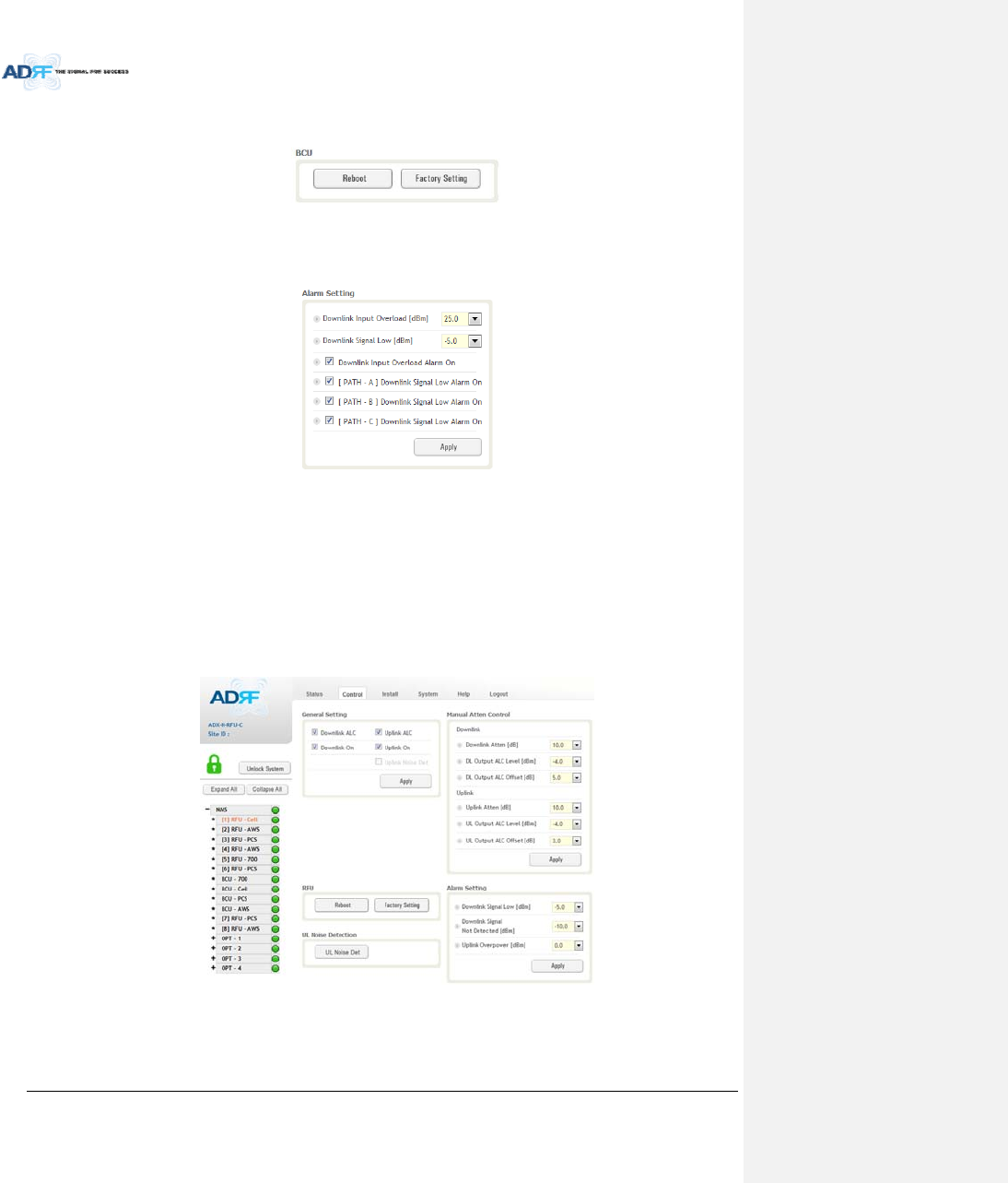
AdvancedRFTechnologies,Inc. 87
8.2.3.2.2 Reboot/FactorySetting
AllowstheuserrebootorrestorefactorysettingsoftheBCU.
Figure8‐39Control–BCUReboot/FactorySetting
8.2.3.2.3 AlarmSetting
Figure8‐40Control–BCUAlarmSetting
DownlinkInputOverload:AllowstheusertospecifythelevelatwhichtheDLInputOverloadalarmis
triggered.Valuesrangefrom0dBmto+25dBm.
DownlinkSignalLow:AllowstheusertospecifythelevelatwhichtheDLSignalLowalarmistriggered.
Valuesrangefrom‐10dBmto+20dBm.
DownlinkInputOverloadAlarmOn:AllowstousertoenableordisabletheInputOverloadAlarm
[Path–A/B/C]DownlinkSignalLowAlarmOn:AllowstheusertoenableordisabletheDLSignalLow
alarmforeachRFpath.
8.2.3.3 Control–RFU
Figure8‐41Control‐RFU
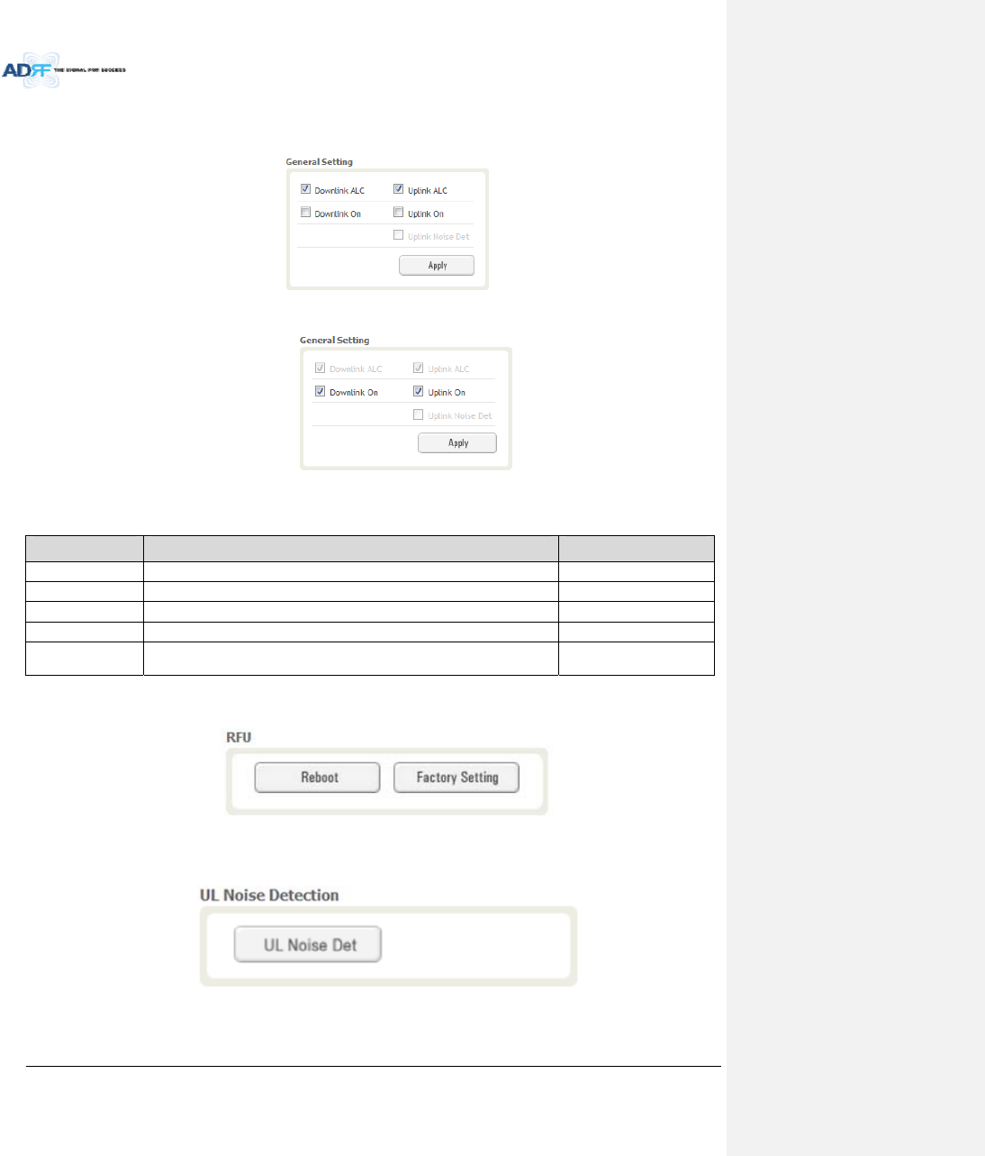
AdvancedRFTechnologies,Inc. 88
8.2.3.3.1 GeneralSetting
Toenableanyofthesettings,clickonthecheckboxandclicktheApplybutton.
Figure8‐42GeneralSetting(Control–RFU)(Admin)
Figure8‐43GeneralSetting(Control–RFU)(User)
Table8‐14DescriptionforGeneralSetting
NameDescriptionAvailableAccounts
DownlinkALCEnablesordisablesDownlinkALCAdministrator
UplinkALCEnablesordisablesUplinkALCAdministrator
DownlinkONEnablesordisablestheRFUDownlinkpath Administrator,User
UplinkONEnablesordisablestheRFUUplinkpathAdministrator,User
UplinkNoiseDetDisplaysifthemoduleisturnedonoroffduetotheULNoiseDetection
Routine
Administrator
8.2.3.3.2 Reboot/FactorySetting
AllowstheuserrebootorrestorefactorysettingsoftheRFU.
Figure8‐44Reboot&FactorySetting(Control–RFU)
8.2.3.3.3 UplinkNoiseDetection(AdminOnly)
Figure8‐45ULNoiseDetection(Control–RFU)
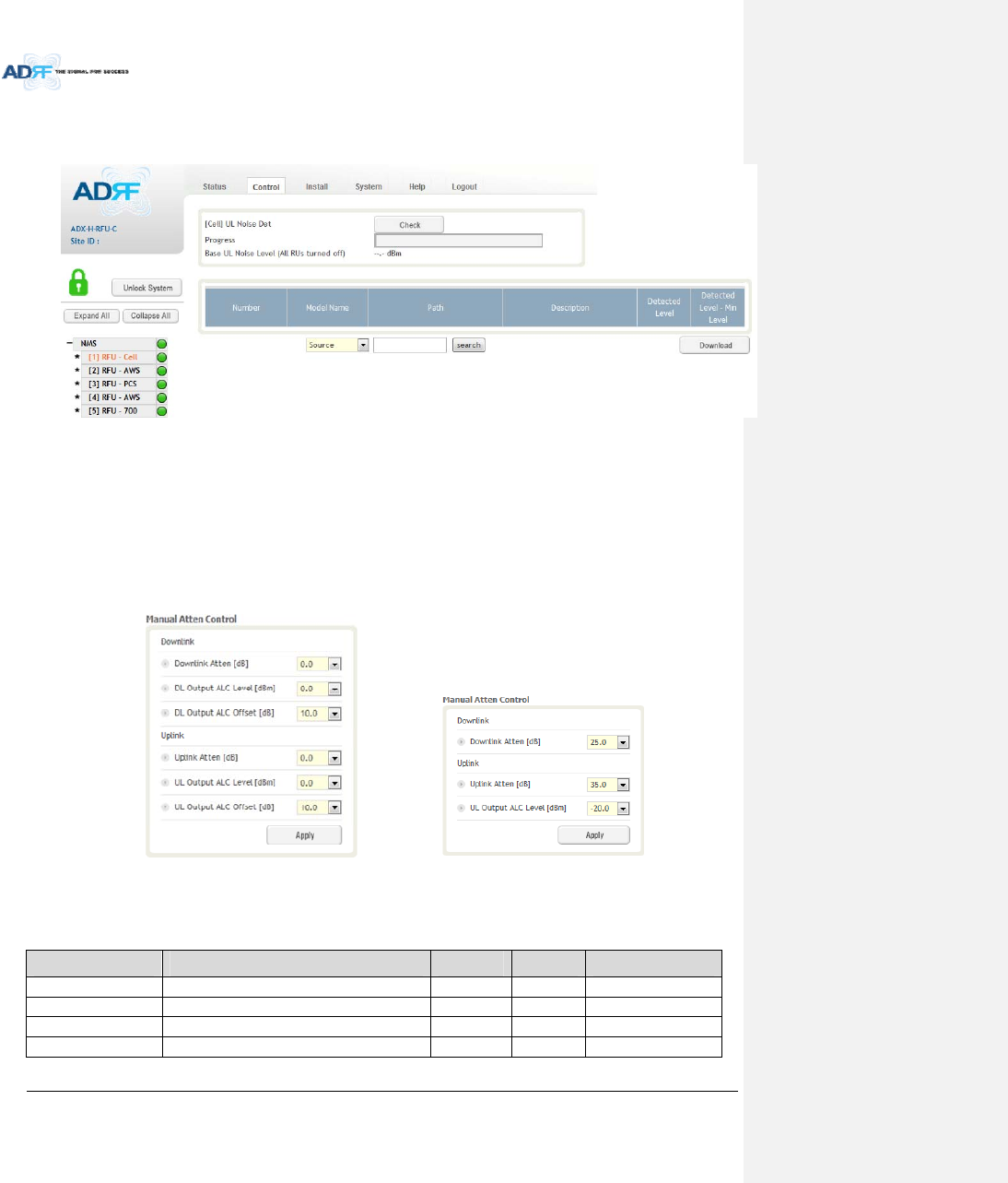
AdvancedRFTechnologies,Inc. 89
The“ULNoiseDet”buttonwilltakeyoutotheULNoiseDetectionpagewhichwillallowyoutoruntheULNoise
Detectionroutine.
Figure8‐46ULNoiseDetection‐PCSband
TheAutoULnoisemeasurementroutinecanberunbyclickingontheCheckbutton.AfterallULnoise
measurementhavebeentaken,thelevelsforeachULpathwillbedisplayedandalongwiththedifference
betweenminimumdetectlevelandmeasureddetectlevel.
TheuserwillbeabletoseewhichpathisgeneratingtheelevatedULnoiselevelbasedonthemeasureddetect
levelanddifferencevalue.
TonavigatebacktotheRFUcontrolpage,clickontheControltabagain.
8.2.3.3.4 ManualAttenControl
(Admin)(User)
Figure8‐47ManualAttenuatorControlSetting(Control–RFU)
Table8‐15DescriptionforMainGainControlSetting(Control–RFU)
NameDescriptionRangeStepAvailableAccounts
DownlinkAttenuatorDownlinkAttenuatortobeadjustedmanually 0~25dB 0.5dB Administrator,User
UplinkAttenuatorUplinkAttenuatortobeadjustedmanually 0~35dB 0.5dB Administrator,User
DLOutputALCLevelTosettheMaxoutputALClevel‐10~0dBm 0.5dBm Administrator
ULOutputALCLevelTosettheMaxoutputALClevel‐20~0dBm 0.5dBm Administrator,User
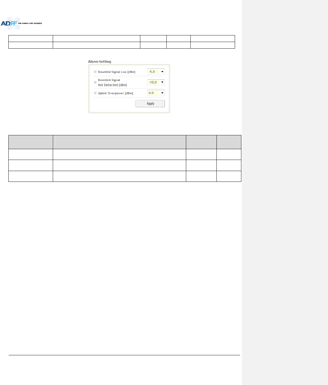
AdvancedRFTechnologies,Inc. 90
DLOutputALCOffsetTosettheMaxoutputALCOffset‐10~0dBm 0.5dBm Administrator
ULOutputALCOffsetTosettheMaxoutputALCOffset‐20~0dBm 0.5dBm Administrator
8.2.3.3.5 AlarmSetting
Figure8‐48AlarmThresholdSetting(Control–RFU)
Table8‐16DescriptionforAlarmThresholdSetting(Control–RFU)
NameDescriptionRangeDefault
threshold
DownlinkSignalLowAllowstheusertospecifytheminimumincomingDLinputsignallevel
beforetriggeringa“DownlinkSignalLow”soft‐failalarm.‐10~20dBm‐5dBm
DownlinkSignalNot
Detected
AllowstheusertospecifytheminimumincomingDLinputsignallevel
beforetriggeringa“DownlinkSignalNotDetected”soft‐failalarm.‐10~20dBm‐10dBm
UplinkOverPowerAllowstheusertospecifythehowstrongtheoutputsignalofuplinkcan
bebeforetriggeringan“UplinkOverPower”HardFailalarm.‐20~0dBm0dBm
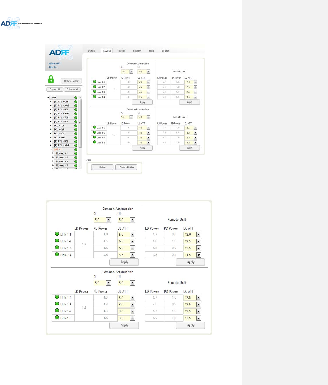
AdvancedRFTechnologies,Inc. 91
8.2.3.4 Control–ODU
Figure8‐49Control–ODU
8.2.3.4.1 OpticAttenuation(AdminOnly)
Figure8‐50OpticAttenuation–ODU
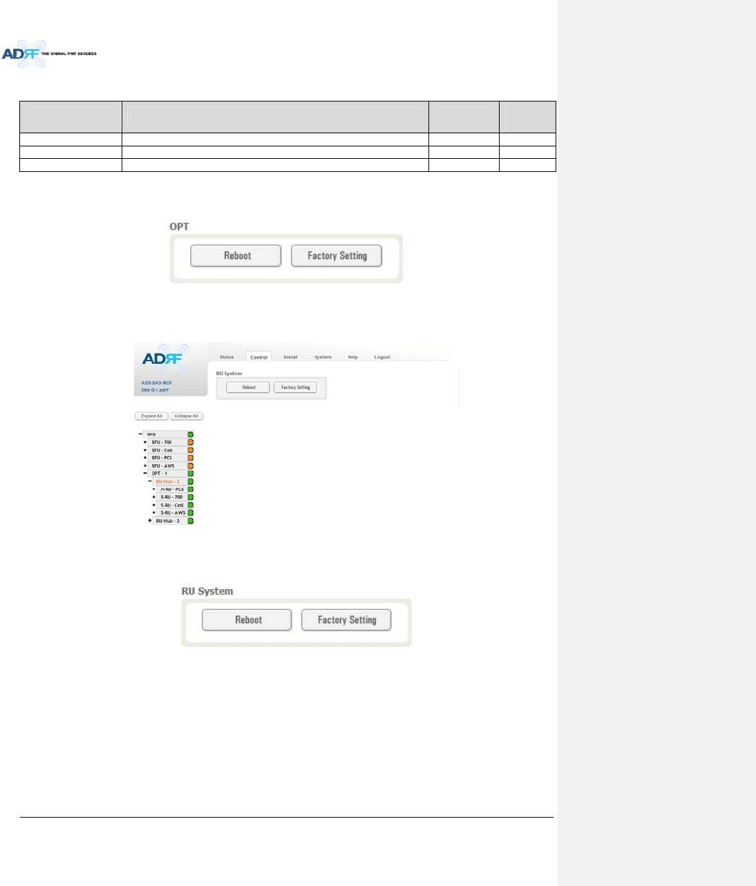
AdvancedRFTechnologies,Inc. 92
Table8‐17DescriptionforOpticAttenuation(Control–ODU)
NameDescriptionRangeDefault
threshold
DL/ULcommonAT
T
AllowstheusertocontroloverallopticDL/ULpathgain. 0~30dB 5dB
DLAT
T
UsedtocompensateDLopticloss.0~13dB 13dB
ULATTUsedtocompensateULopticloss.0~13dB 13dB
8.2.3.4.2 Reboot/FactorySetting
AllowtheusertoperformODUrebootorODUfactorysettings.
Figure8‐51Reboot&factorySetting(Control–ODU)
8.2.3.5 Control–RHHub
Figure8‐52Control–RUHub
8.2.3.5.1 Reboot/FactorySetting
AllowstheusertoperformHPRHubrebootorHPRHubfactorysettings
Figure8‐53Reboot&FactorySetting(Control–RUHub)
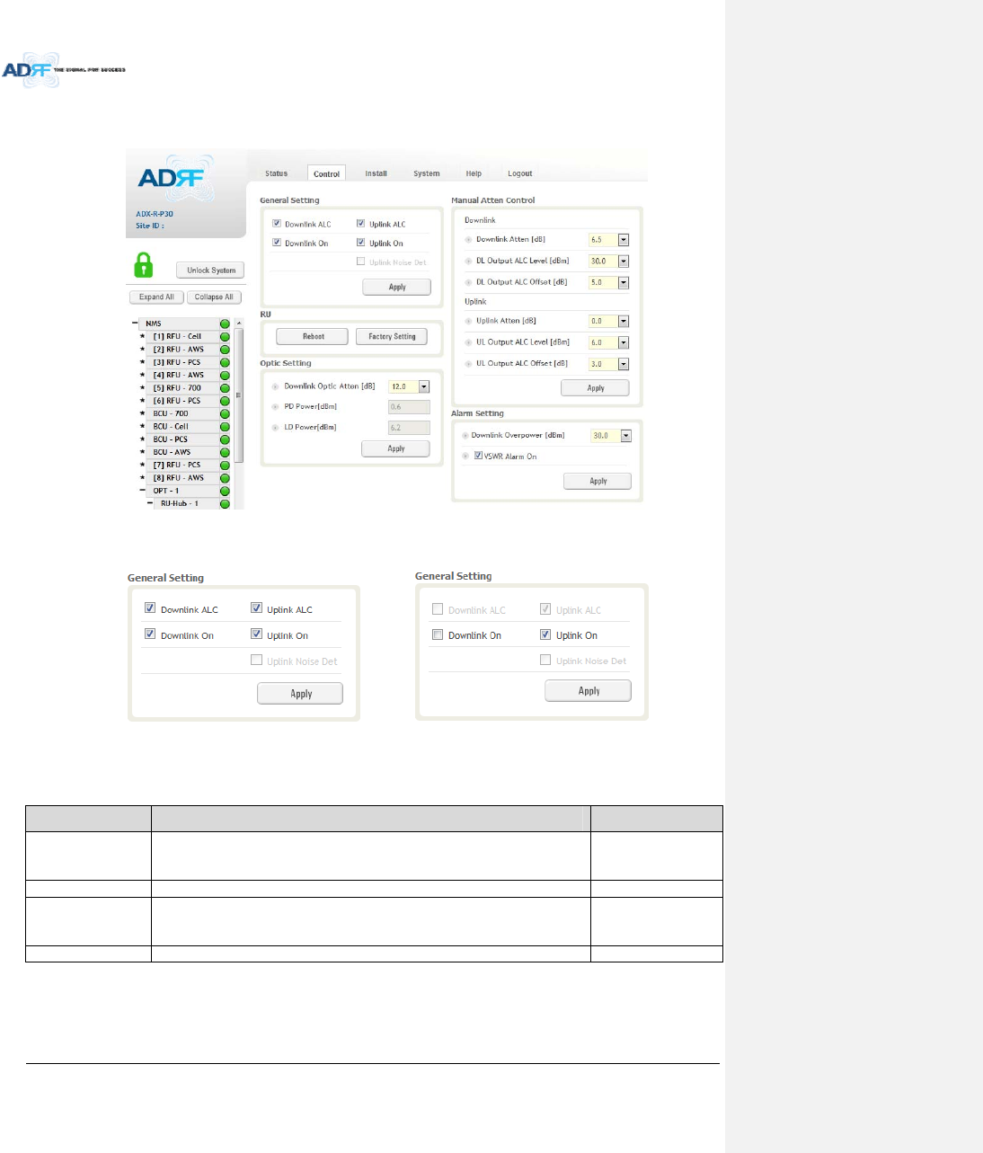
AdvancedRFTechnologies,Inc. 93
8.2.3.6 Control–RemoteModule(MasterorSlaveRU)
Figure8‐54Control–RemoteModule
8.2.3.6.1 GeneralSetting(Admin/User)
(Admin)(User)
Figure8‐55GeneralSetting(Control‐RU)
Table8‐18DescriptionforGeneralSetting(Control‐RU)
NameDescriptionAvailableAccounts
DownlinkALC
ThissettingallowsyoutoenableordisablethedownlinkALCfunction.When
ALCisenabled,thedownlinkoutputpowerwillnotexceedtheDownlink
OutputLevelspecifiedintheManualAttenControlsection.
Administrator
DownlinkOnThissettingallowsyoutoenableordisabletheDownlinkpath. Administrator,User
UplinkALC
ThissettingallowsyoutoenableordisabletheuplinkALCfunction.WhenALC
isenabled,theUplinkoutputpowerwillnotexceedtheUplinkOutputLevel
specifiedintheManualAttenControlsection.
Administrator
UplinkOnThissettingallowsyoutoenableordisabletheUplinkpath. Administrator,User
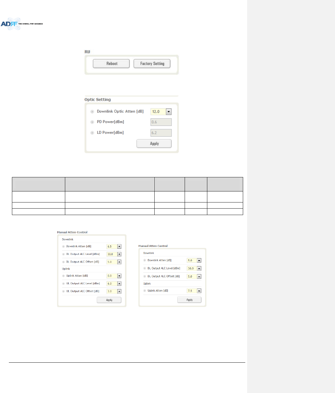
AdvancedRFTechnologies,Inc. 94
8.2.3.6.2 Reboot/FactorySetting
AllowstheusertoRebootorrestoreFactorySettingsontheremotemodule.
Figure8‐56Reboot&factorySetting(Control‐RU)
8.2.3.6.3 OpticSetting(OnlyMasterRU)(AdminOnly)
Figure8‐57OpticSetting(Control‐RU)
Table8‐19DescriptionforOpticSetting(Control‐RU)
NameDescriptionRangeStepAvailable
Accounts
DownlinkOpticAttenRFattenuatortocompensatetheopticlossof
downlink0~13.0dB0.5dBAdministrator
PDPowerIncomingpowerlevelfromtheODU Administrator
LDPowerOutgoingpowerleveltotheODUAdministrator
8.2.3.6.4 ManualAttenuatorControl
(Admin) (User)
Figure8‐58ManualAttenControl(Control‐RU)
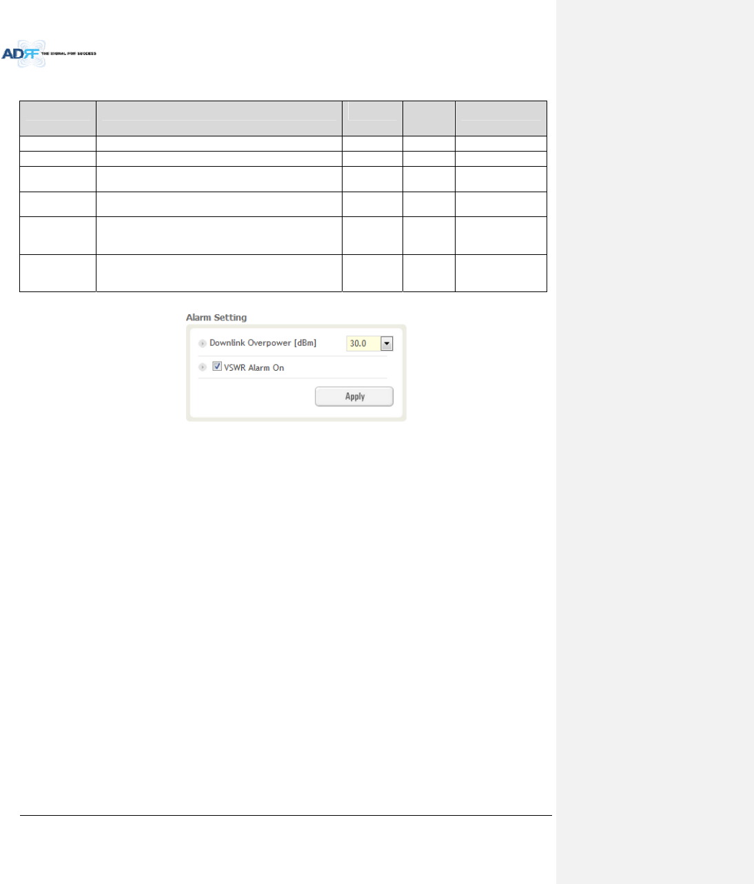
AdvancedRFTechnologies,Inc. 95
Table8‐20DescriptionforManualAttenControl(Control‐RU)
NameDescriptionRangeDefault
threshold
AvailableAccounts
DownlinkAttenAllowstheusertospecifyhowmuchattenuationtouse.0~30dB30dBAdministrator,User
UplinkAttenAllowstheusertospecifyhowmuchattenuationtouse.0~25dB25dBAdministrator,User
DLOutputALC
Level
Theremotemodulewillpreventthedownlinkoutput
powerfromexceedingthespecifiedvalue.5~43dBm43dBmAdministrator,User
ULOutputALC
Level
Thesystemwillpreventtheoutputpowertoexceedthe
specifiedvalue.0~10dBm 5or
6dBmAdministrator
DLOutputALC
Offset
Whentheincomingsignallevelincreases,thesystemwill
notadjustthegainlevelsuntilitreachestheALCOffset
Level.
0~10dB5dBAdministrator,User
ULOutputALC
Offset
Whentheincomingsignallevelincreases,thesystemwill
notadjustthegainlevelsuntilitreachestheALCOffset
Level.
0~10dB3dBAdministrator
8.2.3.6.5 AlarmSetting
Figure8‐59AlarmSetting(Control‐RU)
DLOverPowerLimit:Theoverpoweralarmthresholdcanbeadjustedfrom5~43dBm.+2dBfromtheDL
overpowerlimitwilltriggerasoftfailand>2dBwilltriggerahardfailalarm
VSWRAlarmON:EnableordisablestheVSWRAlarm.
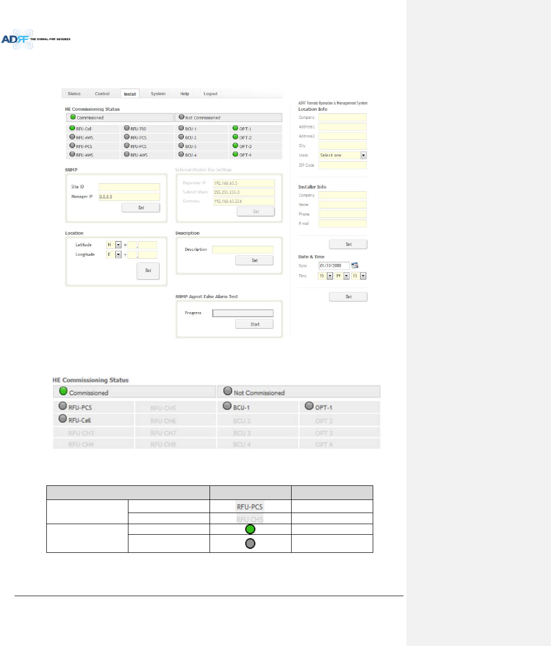
AdvancedRFTechnologies,Inc. 96
8.2.4 InstallTab
8.2.4.1 Install–NMS
Figure8‐60Install‐NMS
8.2.4.1.1 HECommissioningStatus
Figure8‐61HECommissioningStatus(Install–NMS)
Table8‐21DescriptionforHECommissioningStatus(Install–NMS)
StatusDisplayDescription
InstalledStatusPhysicallyInstalledTextisblack
PhysicallyNot‐InstalledTextisgray
CommissioningStatus
SuccessGreen
Failornot
commissionedGray
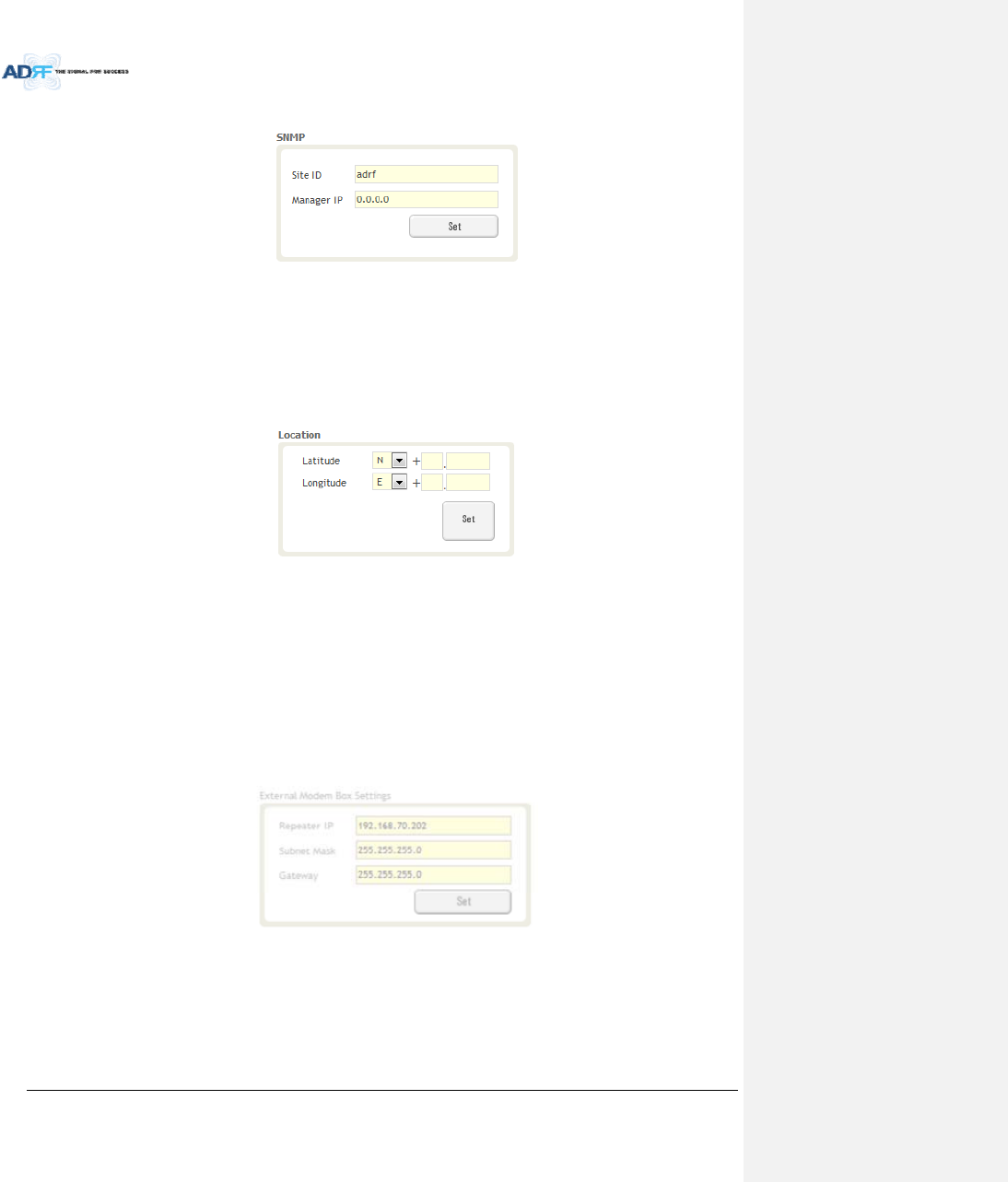
AdvancedRFTechnologies,Inc. 97
8.2.4.1.2 SNMP
Figure8‐62SNMP(Install–NMS)
TheSNMPsectionallowsyoutospecifytheSiteIDandManagerIP.TheSite‐IDisthecodethatisusedto
identifyaparticularmodule.TheManagerIPfieldiswheretheuserinputstheIPaddressoftheNOCsystemthat
isbeingusedtomonitortheSNMPtraps.
8.2.4.1.3 Location
Thissectionallowstheusertoinputthelatitudeandthelongitudeoftherepeater.
Figure8‐63LocationSetting(Install–NMS)
SelectNorSfromthedropdownmenuforLatitude
SelectEorWfromthedropdownmenuforLongitude
Inputthefirst3numbersofthelatitude/longitudeinthetextareaafterthe“+”andbeforethe“.”
Inputthelast6numbersofthelatitude/longitudeinthetextareaafterthe“.”
8.2.4.1.4 ExternalModemBoxSettings
ThissectionallowstheusertospecifyanalternativeIP,SubnetMask,andGatewaysettings.Thesesettings
areenabledwhentheHost/RemoteswitchissettotheRemoteposition.
Figure8‐64ExternalModemBoxSetting(Install–NMS)
8.2.4.1.5 Description
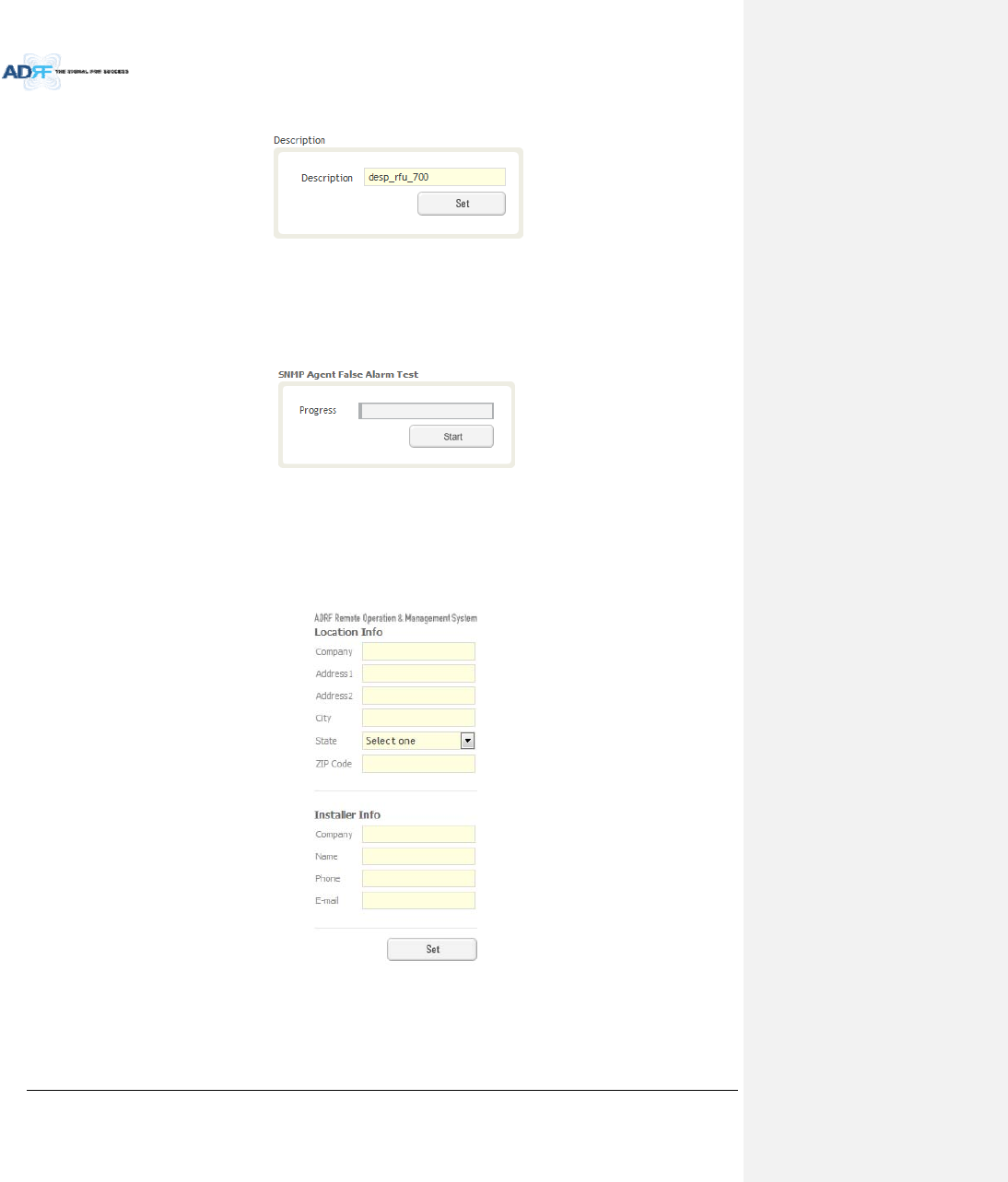
AdvancedRFTechnologies,Inc. 98
ThissectionallowstheusertosavethedescriptionofNMS.
Figure8‐65Description(Install–NMS)
8.2.4.1.6 SNMPAgentFalseAlarmTest
Thissectionallowstheusertogeneratebothsoftandhardfailalarms.Afteralarmsaregenerated,theNOC
canpolltheADXtoseeifalarmsarepresent.Allalarmsgeneratedduringthistestarefalsealarms.
Figure8‐66SNMPAgentFalseAlarmTest(Install–NMS)
8.2.4.1.7 LocationInfo/InstallerInfo
Thissectionallowstheusertospecifytheaddressoftherepeaterandalsotheinformationoftheinstaller.
Figure8‐67 LocationInfo/InstallerInfo(Install–NMS)
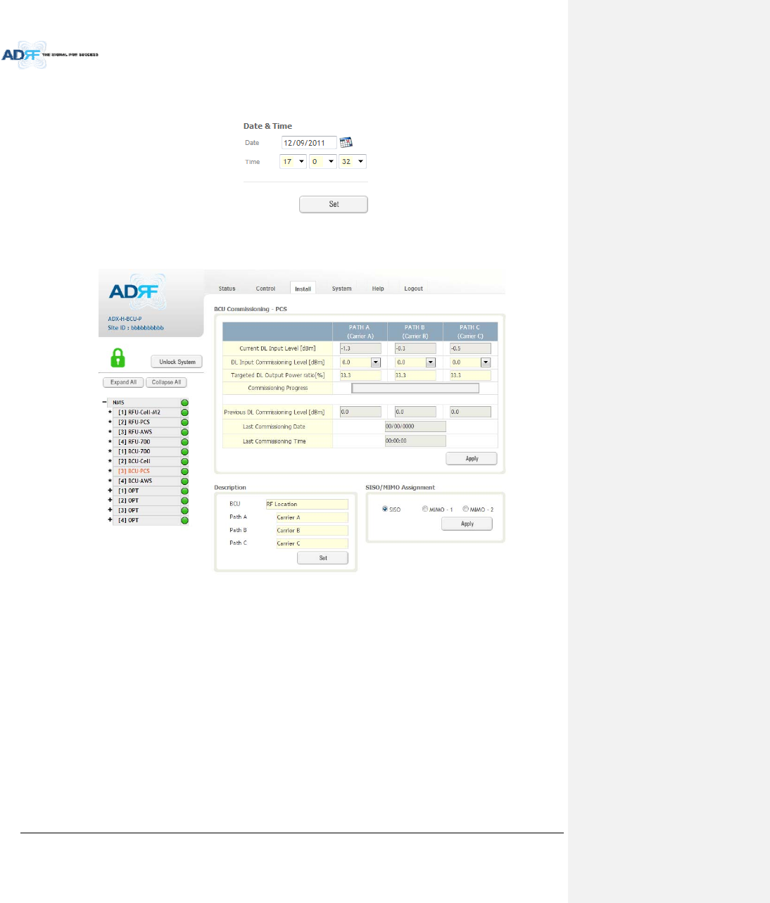
AdvancedRFTechnologies,Inc. 99
8.2.4.1.8 Date&Time
Thissectionallowstheusertospecifythecurrentdateandtime.
Figure8‐68Date&TimeSetting(Install–NMS)
8.2.4.2 Install–BCU
Figure8‐69Install–BCU
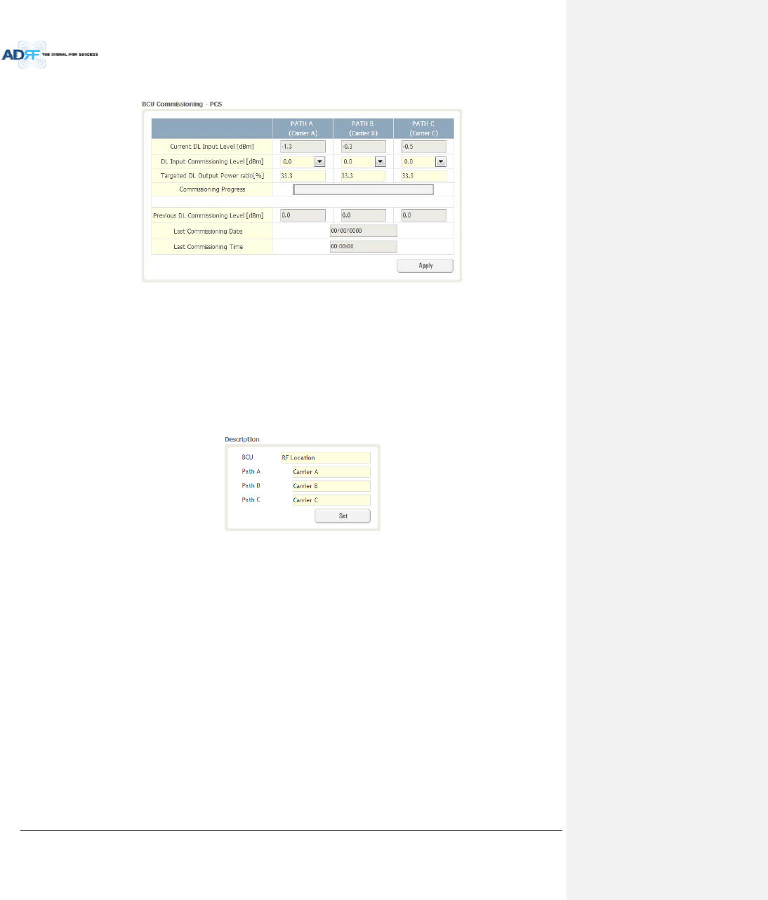
AdvancedRFTechnologies,Inc. 100
8.2.4.2.1 BCUCommissioning
Figure8‐70Install–BCUCommissioning
CurrentDLInputLevel:
DLInputCommissioningLevel:
TargetedDLOutputPowerRatio:
CommissioningProgress:
PreviousDLCommissioningLevel:
LastCommissioningDate:
LastCommissioningTime:
8.2.4.2.2 Description
Figure8‐71Install–BCUDescription
BCU:ThissectionallowstheusertosetthedescriptionofBCU.
PathA/B/C:AllowstheusertospecifyanameforeachRFpath.ThenamesofeachRFpathwill
appearinthecolumnheaders.
8.2.4.3 Install–RFU
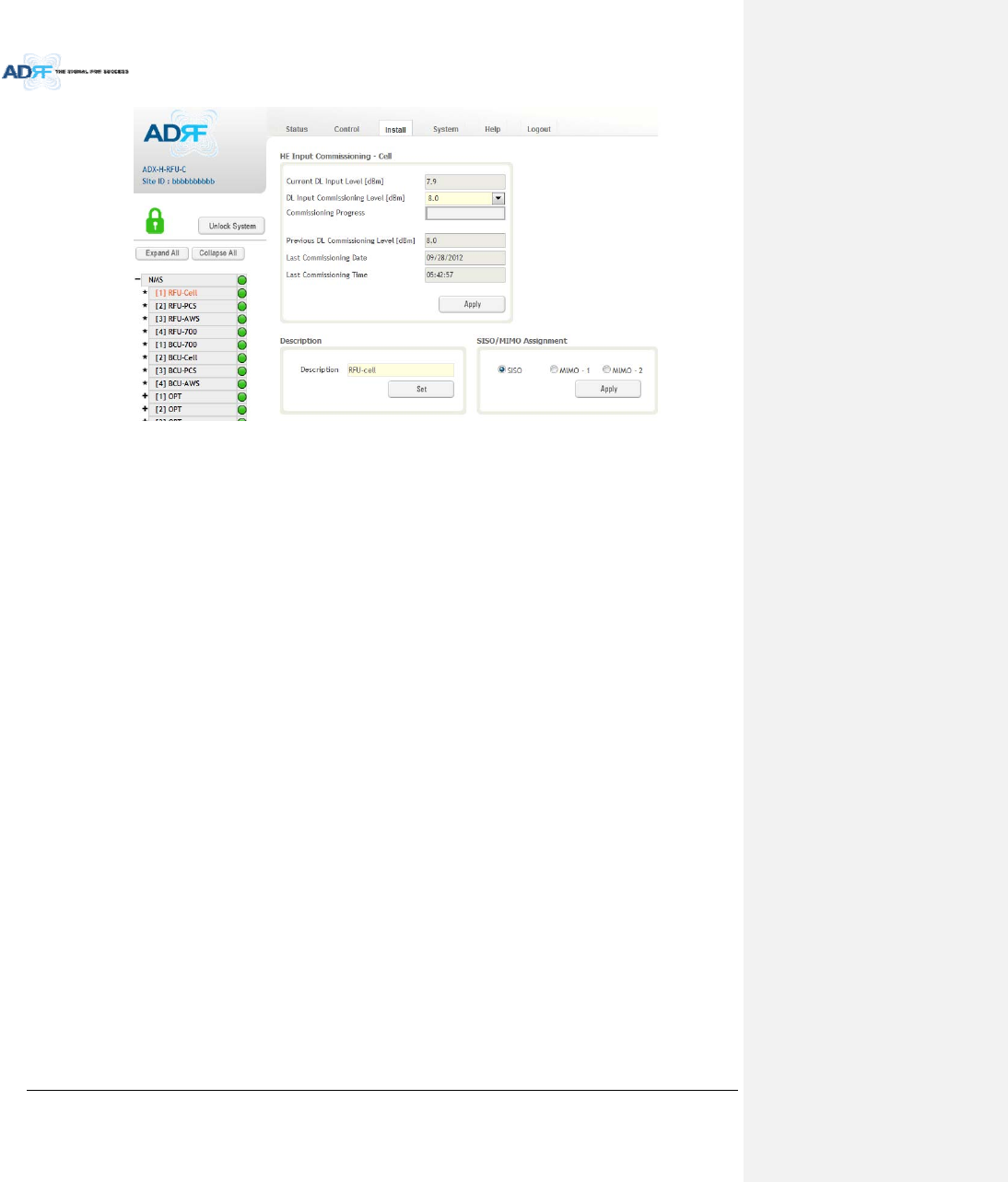
AdvancedRFTechnologies,Inc. 101
Figure8‐72Install‐RFU
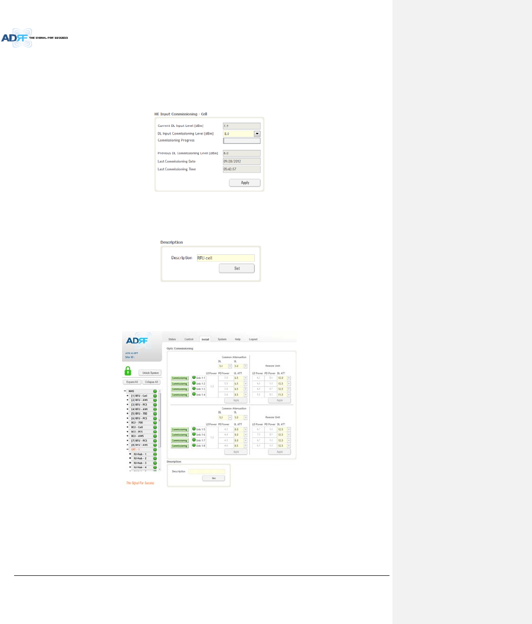
AdvancedRFTechnologies,Inc. 102
8.2.4.3.1 RFUCommissioning
ThissectionallowstheusertoperformRFUcommission.ToperformRFUcommissioning,selectaDLInput
CommissioningLevelfromthedropdownmenuandclickApply.Thecommissioningprogressisdisplayedonthe
CommissioningProgressbar.Anyerrors,warnings,andmessageswillappearviaapopupwindow.Pleasereferto
theADXInstallationGuidetodeterminetheproperRFUcommissioninglevels.
Figure8‐73RFUCommissioning(Install–RFU)
8.2.4.3.2 Description
ThissectionallowstheusertosetthedescriptionofRFU.
Figure8‐74Description(Install–RFU)
8.2.4.4 Install–ODU
Figure8‐75Install–ODU
8.2.4.4.1 OpticCommissioning
Thissectionwillallowtheusertoperformanyopticcompensationifitisnecessary.TheCommissioning
buttonwillturnorangeifopticcompensationisneeded.
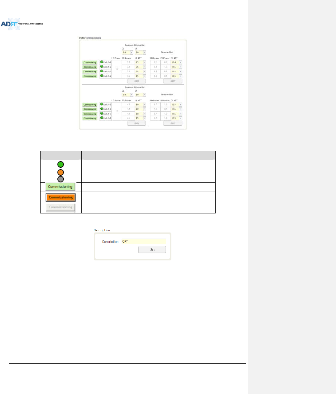
AdvancedRFTechnologies,Inc. 103
Figure8‐76Opticcontrol(Control–ODU)
Table8‐22DescriptionforOpticcontrol(Control–ODU)
Display&ControlDescription
Opticlossislessthan5dBo
Opticlossismorethan5dBo
NotconnectedtoaRU
Noopticlosscompensationisneeded.
Opticlosscompensationisneeded.
NotconnectedtoaRU
8.2.4.4.2 Description
ThissectionallowstheusertosavethedescriptionofODU.
Figure8‐77Description(Install–ODU)
8.2.4.5 Install–HPRHub
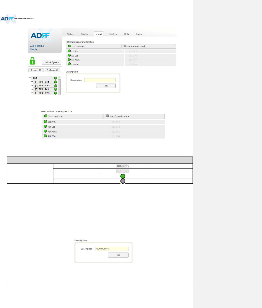
AdvancedRFTechnologies,Inc. 104
Figure8‐78Install‐RUHub
8.2.4.5.1 RUCommissioningStatus
Figure8‐79RUCommissioningStatus(Install‐RUHub)
Table8‐23DescriptionforHPRCommissioningstatus
StatusDisplayDescription
InstalledStatusPhysicallyInstalledTextisblack
PhysicallyNot‐InstalledTextisgray
CommissioningStatusSuccessGreen
FailornotcommissionedGray
8.2.4.5.2 Description
ThissectionallowstheusertosavethedescriptionofHPRHub.
Figure8‐80Description(Install‐RUHub)
8.2.4.6 Install–RemoteModule(MasterorSlaveRU)
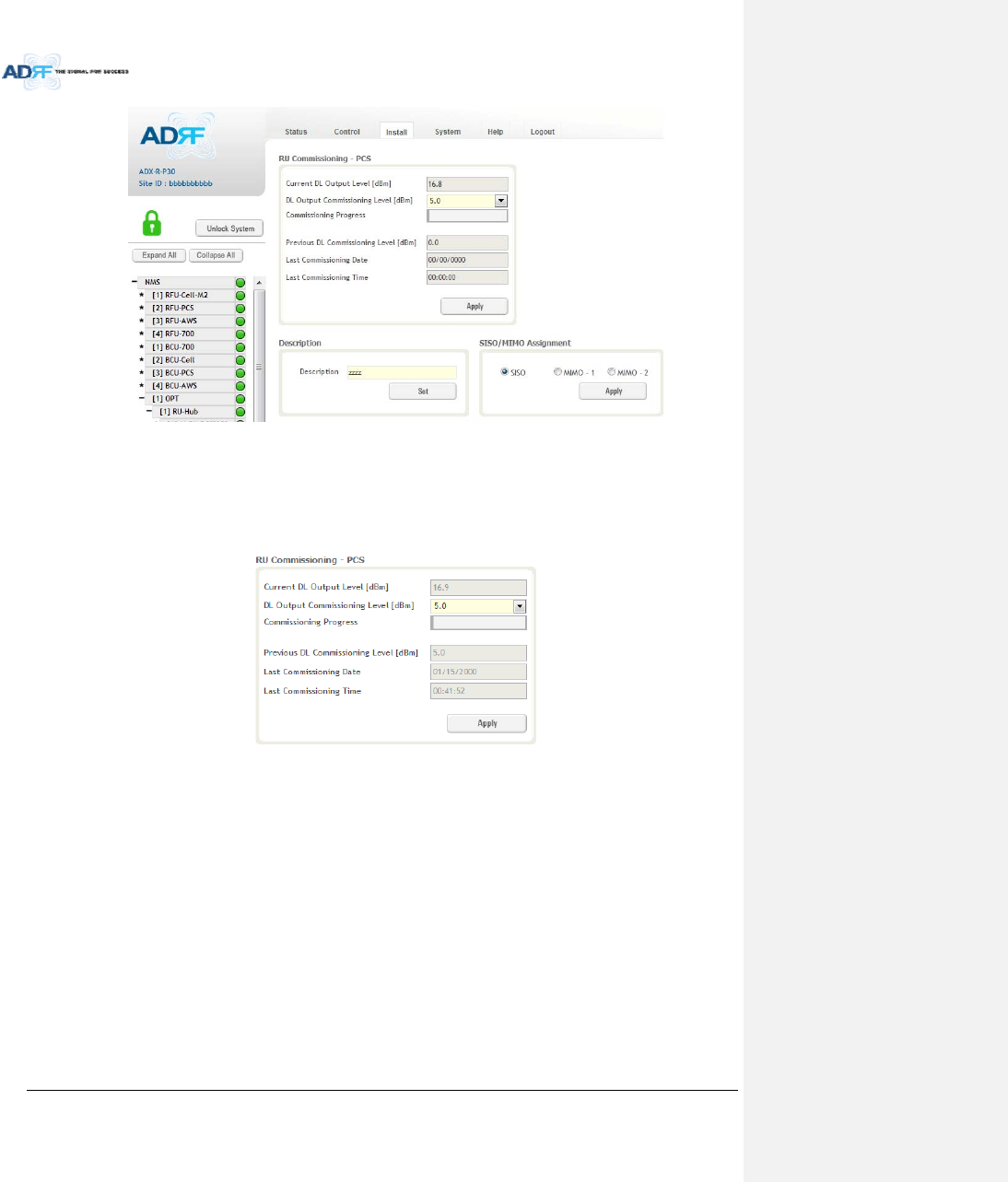
AdvancedRFTechnologies,Inc. 105
Figure8‐81Install‐RemoteModule
8.2.4.6.1 RUOutputCommissioning
ThissectionallowstheusertoperformHPRcommission.ToperformHPRcommission,selectaDLOutput
CommissioningLevelfromthedropdownmenuandthenclickApply.Thecommissioningprogressisdisplayedon
theCommissioningProgressbar.Anyerrors,warnings,andmessageswillappearviaapopupwindow.
Figure8‐82RUOutputCommissioning(Install‐RU)
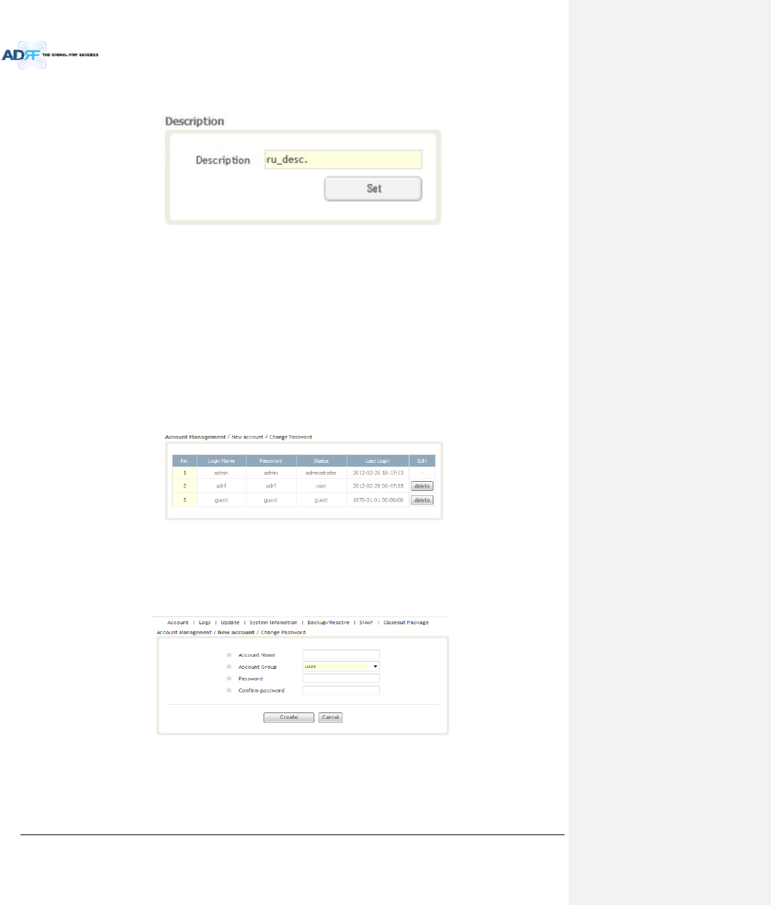
AdvancedRFTechnologies,Inc. 106
8.2.4.6.2 Description
Thissectionallowstheusertosavethedescriptionofremotemodule.
Figure8‐83Description(Install‐RemoteModule)
8.2.5 System
TheSystemtaballowstheusertoperformfirmwareupdates,uploadcloseoutpackages,viewanychangesto
thesystem,backupexistingconfiguration,andadd/removeuseraccounts,andchangethelogincredentialsofthe
Administrator.
8.2.5.1 System:Account
8.2.5.1.1 System:Account‐AccountManagement(AdminOnly)
TheAccountManagementsectionallowstheAdministratortodeleteanyuser/guestaccount.Pleasenote
thattheAccountManagementsectionisonlyavailableifyouareloggedintothesystemastheAdministrator.To
deleteauser/guestaccountclickontheAccountManagementlinkandundertheDeletecolumn,clickonthe
deletebutton.
Figure8‐84AccountManagement
8.2.5.1.2 System:Account‐NewAccount(AdminOnly)
TheNewaccountsectionallowstheAdministratortocreateanewuser/guestaccount.Pleasenotethatthe
newaccountsectionisonlyavailableifyouareloggedintothesystemastheAdministrator.Tocreateanew
user/guestaccountclickonthenewaccountlinkandfillinthefieldshighlightedinyellowasshownbelow.
Figure8‐85NewAccount
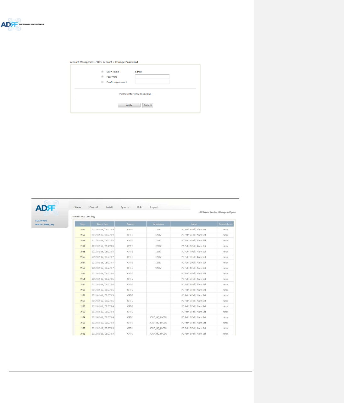
AdvancedRFTechnologies,Inc. 107
8.2.5.1.3 System:Account‐ChangePassword
TheChangePasswordsectionallowsthecurrentuserwhoisloggedintothesystemtochangetheirlogin
credentials.
Figure8‐86ChangePassword
8.2.5.2 System:Logs
8.2.5.2.1 System:Logs‐EventLog
Thissectiondisplayssystemeventsthathavetakenplace.TheEventLogdisplayswhohasmadethechanges,
thetimeanddateofwhentheeventtookplace,andwhatchangesweremadetothesystem.TheSystemLog
tracksthefollowingevents:
SystemInitiation
AlarmSet
AlarmClear
Figure8‐87EventLog
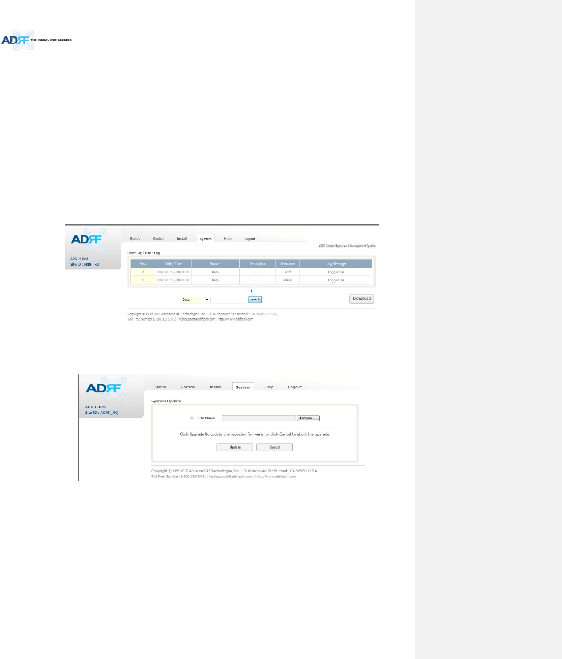
AdvancedRFTechnologies,Inc. 108
8.2.5.2.2 System:Logs‐UserLog
Thissectiontracksuseractivitywithinthesystem.TheUserLogdisplayswhohasmadethechanges,thetime
anddateofwhentheeventtookplace,andwhatchangesweremadetothesystem.TheUserLogtracksthe
followingitems:
Login/Logoutactivity
Changestogain/attenuation/outputvalues
Systemeventgeneratedbyuser(firmwareupdate,backup/resote,create/deleteaccount)
DASNavigationTreeLock/Unlock
Descriptionchange
Repeater/installerinformationchange
Settingdate/time
Figure8‐88UserLog
8.2.5.3 System:Update
Toperformafirmwareupdate,clickontheSystem:Updatetabandthefollowingscreenwillshowup.
Figure8‐89Systemupdate
Clickonthe‘Browse’buttonandlocatethefirmwarefile.
ClickontheUpdatebuttontoperformthefirmwareupdate.
Oncethefirmwareupdateiscomplete,thefollowingmessagewillappear.
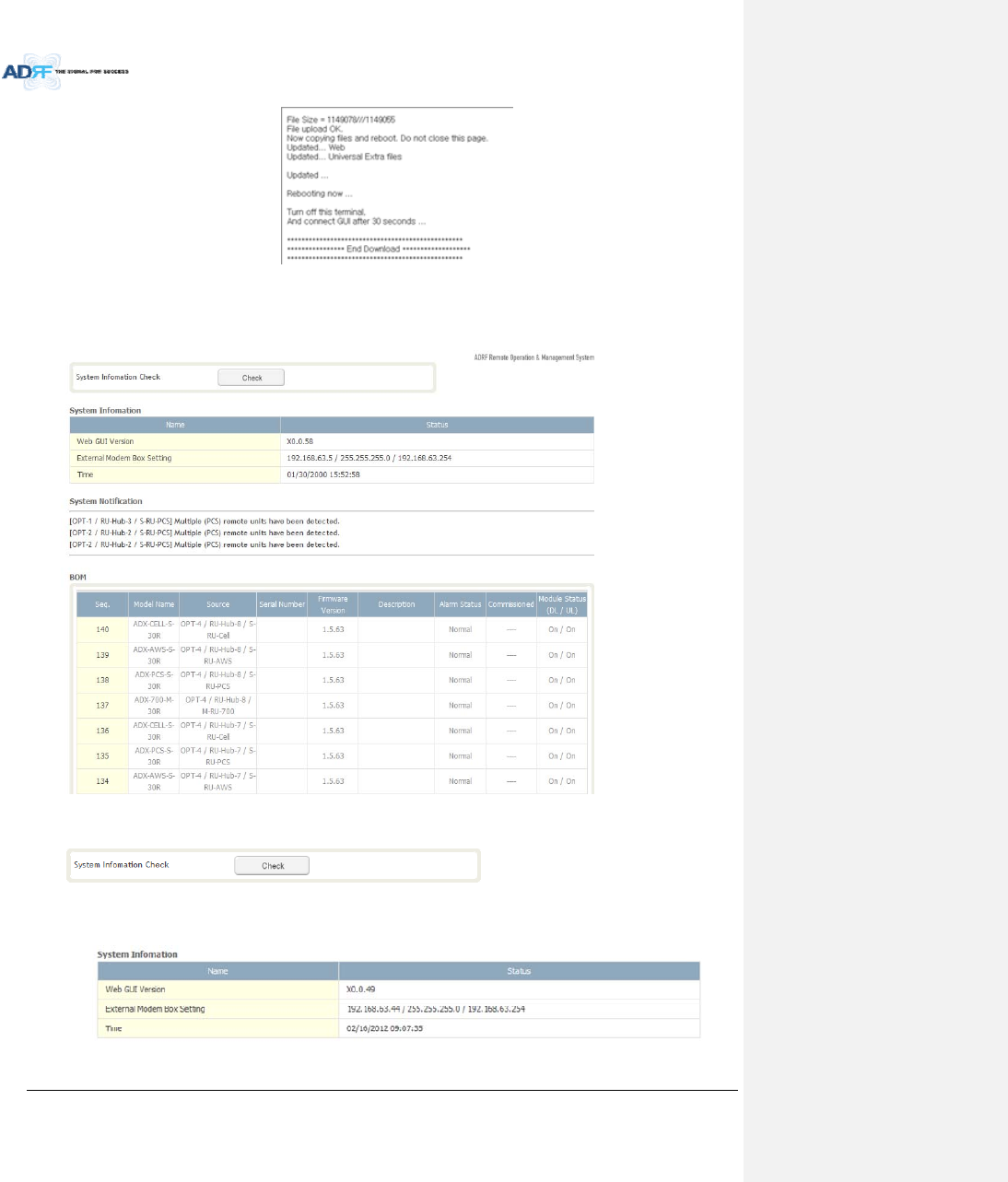
AdvancedRFTechnologies,Inc. 109
Figure8‐90MessageafterSystemupdateiscomplete
8.2.5.4 System:SystemInformation
8.2.5.4.1 System:SystemInformation
SystemInformationCheck
TheSystemInformationCheckbuttonwillchecktheADXconfiguationandreportpossiblediscrepancies.
SystemInformation
ThissectiondisplaysthegeneralsysteminformationoftheADXDAS.
Figure8‐91SystemInformation
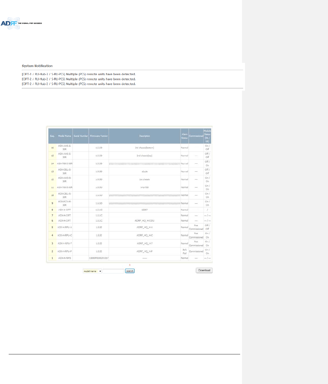
AdvancedRFTechnologies,Inc. 110
SystemNotification
Thissectionisdisplayedonlywhenthefollowingconditionsarepresent:
‐ WhenmultipleremotemoduleswithsamefrequencybandexistinaRU.
‐ WhentheremotemoduledoesnotmatchwiththeRFUbeingused.
Figure8‐92SystemNotification
BOM
BOMdisplaysallpartsthatareconnectedtotheADX‐H‐NMS.
TheBOMcanbedownloadedasaCSVfilebyclickingthe‘Download’buttonatthebottomright.
Figure8‐93Billofmaterial
8.2.5.5 System:Backup/Restore
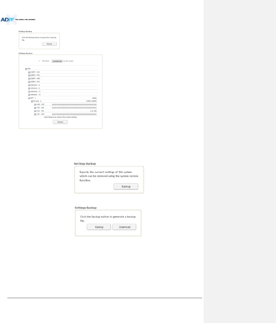
AdvancedRFTechnologies,Inc. 111
SettingsBackup
ClickingtheBackupwillcreateatemporarybackupfilestoredinsideoftheADX.Oncethefileiscreated,itwill
needtobedownloadedtoacomputer.Adownloadbuttonwillappearafterthebackupfilehasbeencreated.If
theADXispowercycledorrebooted,thenthetemporarybackupfilewillbelost.Werecommenddownloading
thebackupfileimmediatelyafterithasbeencreated.ClickontheDownloadbuttontodownloadthebackupfile.
Figure8‐94SettingBackup(Before)
Figure8‐95SettingBackup(After)
SettingRestore
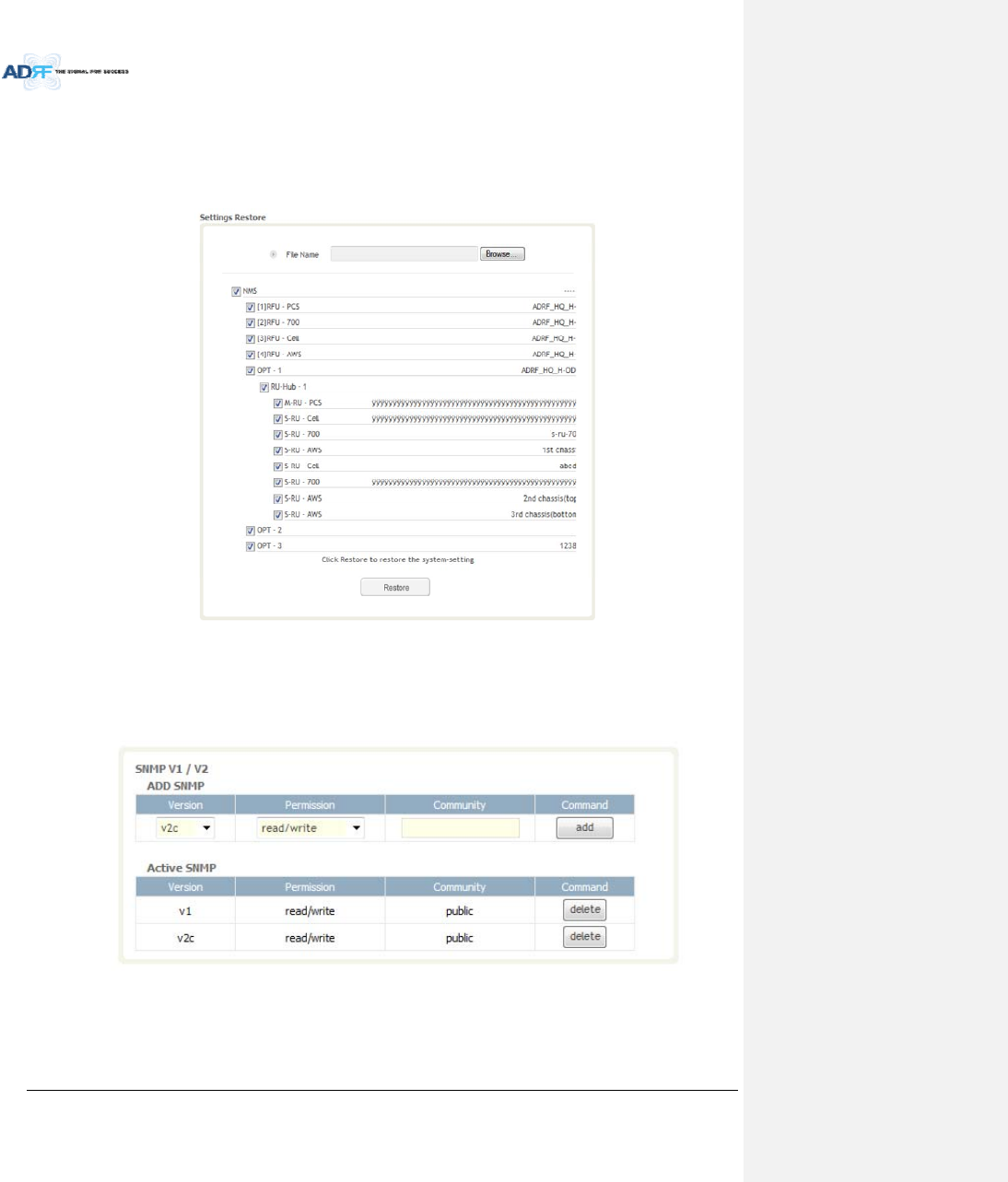
AdvancedRFTechnologies,Inc. 112
Restorefunctioncanbeusedtorestorethesavedsettingsfromthebackupfile.Oncethebackupfileisloaded,
thetreeinthefigurebelowwillappear.Checktheboxesofthemodulesthatyouwouldliketorestoreandthen
clickthe“Restore”buttonatthebottomonthissection.
WerecommendcreatinganewbackupfileifaddingorremovingmodulesfromtheADX.Discrepancies
betweenthebackupfileandtheexistingtreecouldcauserestoreerrors.
Figure8‐96SettingRestore
8.2.5.6 System:SNMP
SNMPV1/V2
ThissectionallowsyoutoaddcommunitystringsforSNMPv1andv2.
Figure8‐97SNMPV1/V2
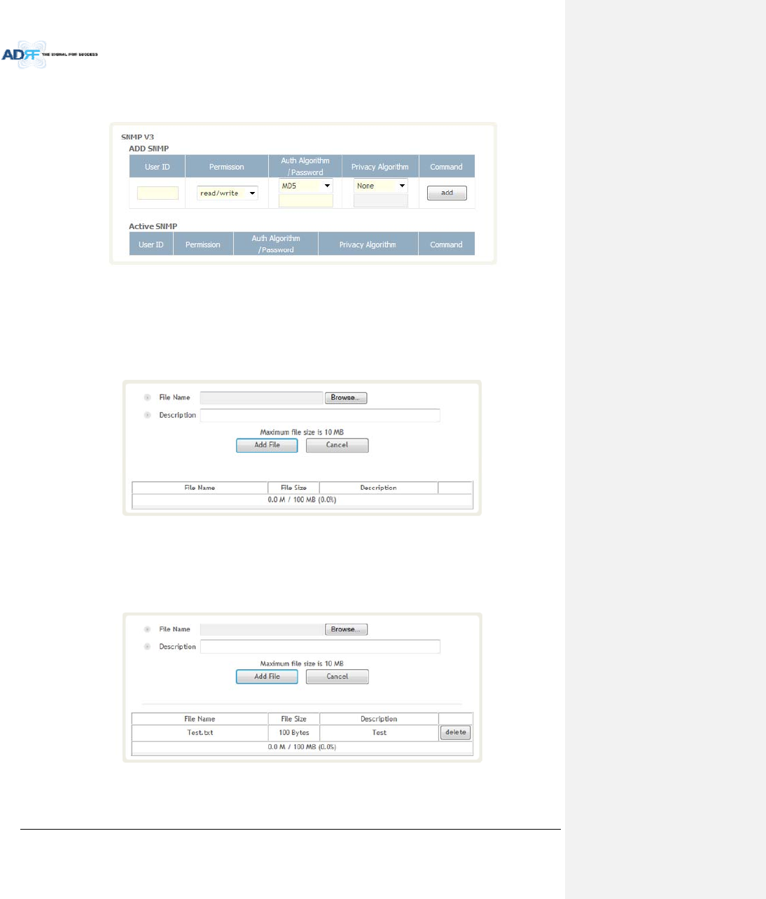
AdvancedRFTechnologies,Inc. 113
SNMPV3
ThissectionallowstheusertoaddaccountsforSNMPv3.
Figure8‐98SNMPV3
8.2.5.7 System:CloseoutPackage
ThecloseoutpackagesectionwillallowtheusertouploaddocumentstotheADX‐H‐NMS.Themaximumfile
sizeforeachuploadislimitedto10MB.Thetotalamountofspaceavailableforuploadingdocumentis100MB.
Pleasedonotusethissectionastheprimarystoragelocationofyourdocuments.Documentsmaybecome
unavailableifthesystemgoesdown.
Figure8‐99System‐CloseoutPackage
Touploaddocumentstothemodule,clickonthe“Browse”buttonandlocatethefilethatyouwouldliketo
upload,thenenterinaDescriptionofthefilebeinguploaded.Afterwards,clickonthe“AddFile”buttontoupload
thefile.Belowiswhatyouwillseeafterthefileupload.Todeletethefile,clickonthedeletebuttonlocatedinthe
lastcolumn.
Figure8‐100System‐CloseoutPackageafterthefileupload

AdvancedRFTechnologies,Inc. 114
8.2.6 Help
Ifaninternetconnectionisavailable,clickingontheHelpTabwillredirecttheusertoourTechnicalSupport
page.
Figure8‐101Help
8.2.7 Logout
ClickingtheLogoutbuttonwilllogthecurrentuseroffthesystem.
8.3 GuestMode
Whenloggingintothesystemasaguest,theguestwillonlyhaveread‐onlyprivilegesandwillnotbeableto
makeanychangestothesystem.
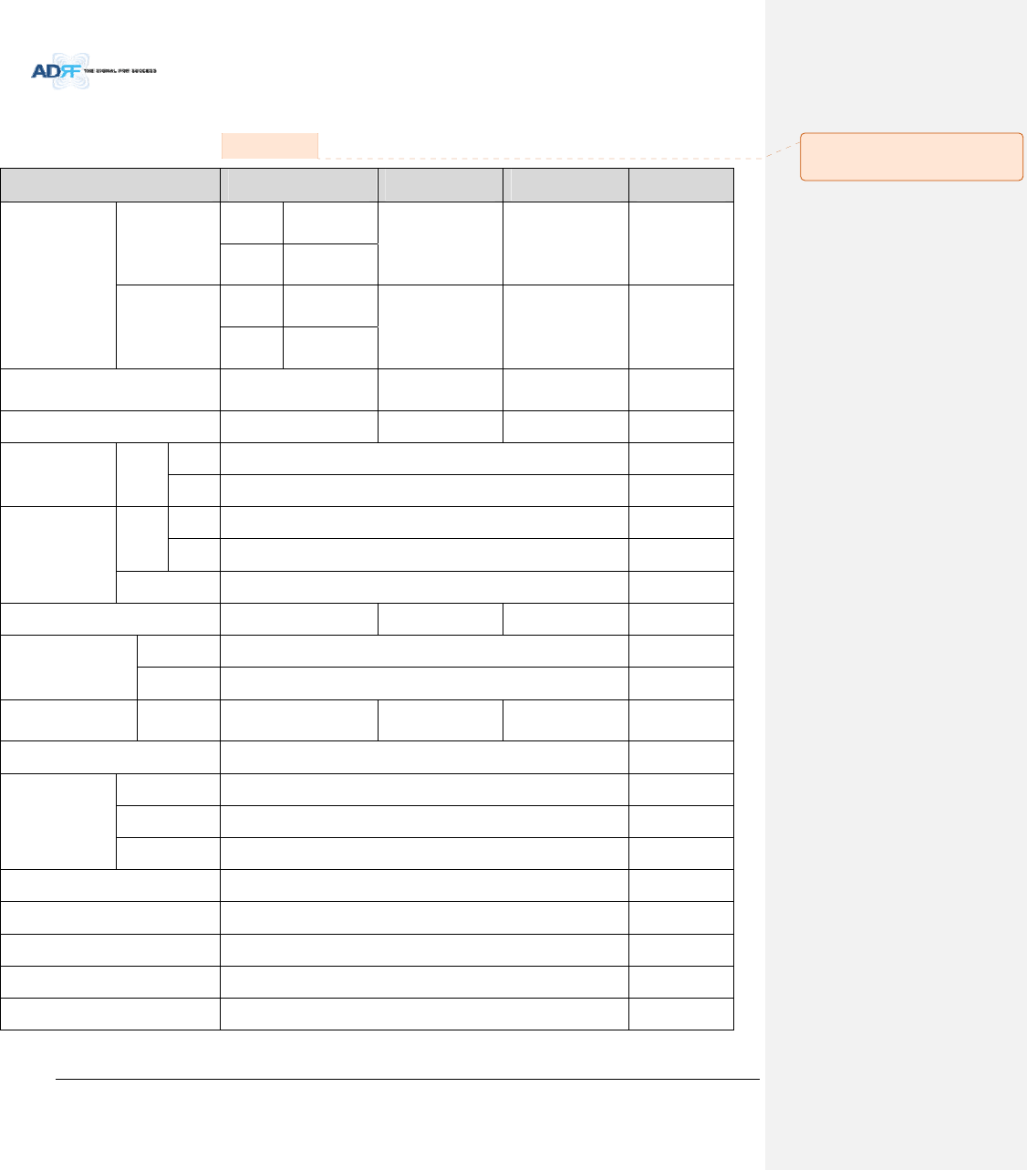
AdvancedRFTechnologies,Inc. 115
9. SYSTEM‐WIDESPECIFICATION(TOBECONNECTEDTOHEVIAOPTICLINE)
700LTE/CELL/SMR800 Specifications.
700F CELL SMR800 Comments
Frequency
Downlink
Lower
ABC 728-746MHz
869-894MHz 851~869MHz SMR800 is not
for FCC approval
Upper
C 746-757MHz
Uplink
Lower
ABC 698-716MHz
824-849MHz 806~824MHz
Upper
C 776-787MHz
Support Band Width 16+11MHz
(Lower ABC + Upper C) 25MHz 18MHz
DL Input Range 0~25dBm 0~25dBm 0~25dBm
Gain Range
D/L 18~43dB, 0.5dB step, ATT range: 0~25dB
U/L -5~30dB, 0.5dB step, ATT range: 0~35dB
Attenuation
Range
D/L 0~25dB
U/L 0~35dB
Accuracy 0~15dB: < ±0.5dB, 15~35dB: < ±1.0dB, 35dB~: < ±1.5dB
Gain Flatness < ±2.0dB < ±2.0dB < ±2.0dB
Composite Maximum
Output Power
Downlink 43dBm±1dB
Uplink -15dBm±1dB
Noise Figure @max gain 5.0dB
@ Band Center
5.0dB
@ Band Center
5.0dB
@ Band Center
VSWR < 1.5:1
EVM
LTE Uplink (< 12.5%), downlink (< 8%)
EVDO Uplink (< 14.75%), downlink (< 12.5%)
CDMA2000 Uplink (< 14.75%), downlink (< 14.75%)
Optical Loss 0~10dBo
System Delay <2us @0dBo optic loss
Spurious FCC, 3GPP TS 36.104, 3GPP2 C.S0010-C
Operating Temperature -30~55C
Operating Humidity 5-90%
메모 [H23]: SMR800 의경우
FCC 인증에서제외함.(ACP 문제점)
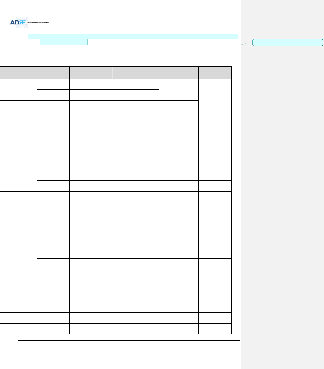
AdvancedRFTechnologies,Inc. 116
NOTE:IndustryCanadaCellularband20dBnominalbandisfromXMHztoYMHzforDownlinkandfromX
MHztoYMHzforUplink.
2. PCS/AWS/BRS Specifications.
PCS AWS BRS Comments
Frequency
Downlink 1930~1995MHz 2110~2155 MHz
2496~2690 MHz
Uplink 1850~1915MHz 1710~1755 MHz
Support Band Width 65MHz 45MHz 194MHz
DL Input Range 0~25dBm 0~25dBm
+12~37dBm
(Medium Mode)
-15~12dBm
(Low Mode)
Gain Range
D/L 21~46dB, 0.5dB step, ATT range: 0~25dB
U/L -5~30dB, 0.5dB step, ATT range: 0~35dB
Attenuation
Range
D/L 0~25dB
U/L 0~35dB
Accuracy 0~15dB: < ±0.5dB, 15~35dB: < ±1.0dB, 35dB~: < ±1.5dB
Gain Flatness < ±2.0dB < ±2.0dB < ±2.0dB
Composite Maximum
Output Power
Downlink 46dBm±1dB
Uplink -15dBm±1dB
Noise Figure @max gain 5.0dB
@ Band Center
5.0dB
@ Band Center
5.0dB
@ Band Center
VSWR < 1.5:1
EVM
LTE Uplink (< 12.5%), downlink (< 8%)
EVDO Uplink (< 14.75%), downlink (< 12.5%)
CDMA2000 Uplink (< 14.75%), downlink (< 14.75%)
Optical Loss 0~10dBo
System Delay <2us @0dBo optic loss
Spurious FCC, 3GPP TS 36.104, 3GPP2 C.S0010-C
Operating Temperature -30~55C
Operating Humidity 5-90%
메모 [Y24]: Addition14/05/12
AdvancedRFTechnologies,Inc. 117
NOTE:IndustryCanadaCellularband20dBnominalbandisfromXMHztoYMHzforDownlinkandfromX
MHztoYMHzforUplink.
3. SMR900 Specifications.
SMR9000+Paging Comments
Frequency
Downlink 929~942MHz
Uplink 896~903MHz
Support Band Width DL:13MHz,
UL: 7MHz
DL Input Range 0~25dBm
Gain Range
D/L 18~43dB, 0.5dB step, ATT range: 0~25dB
U/L -5~30dB, 0.5dB step, ATT range: 0~40dB
Attenuation
Range
D/L 0~25dB
U/L 0~40dB
Accuracy 0~15dB: < ±0.5dB, 15~35dB: < ±1.0dB, 35dB~: <
±1.5dB
Gain Flatness < ±2.0dB
Composite Maximum
Output Power
Downlink 43dBm±1dB
Uplink -15dBm±1dB
Noise Figure @max gain 5.0dB@ Band Center
VSWR < 1.5:1
EVM
LTE Uplink (< 12.5%), downlink (< 8%)
EVDO Uplink (< 14.75%), downlink (< 12.5%)
CDMA2000 Uplink (< 14.75%), downlink (< 14.75%)
Optical Loss 0~10dBo
System Delay <2us @0dBo optic loss
Spurious FCC, 3GPP TS 36.104, 3GPP2 C.S0010-C
Operating Temperature -30~55C
Operating Humidity 5-90%
메모 [Y25]: Addition14/05/12
메모 [H26]: 해당제품의SPEC 의경우
향후추가될제품의SPEC 임.
AdvancedRFTechnologies,Inc. 118
NOTE:IndustryCanadaCellularband20dBnominalbandisfromXMHztoYMHzforDownlinkandfromX
MHztoYMHzforUplink.
4. WCS Specifications.
WCS Comments
Frequency
Downlink 2305-2315MHz
Uplink 2350-2360MHz
Support Band Width 10MHz
DL Input Range +12~37dBm(Medium)
-15~12dBm(Low)
Gain Range
D/L 19.8~44.8dB, 0.5dB step, ATT range: 0~25dB
U/L -5~30dB, 0.5dB step, ATT range: 0~40dB
Attenuation
Range
D/L 0~25dB
U/L 0~40dB
Accuracy 0~15dB: < ±0.5dB, 15~35dB: < ±1.0dB, 35dB~: <
±1.5dB
Gain Flatness < ±2.0dB
Composite Maximum
Output Power
Downlink 44.8dBm±1dB
Uplink -15dBm±1dB
Noise Figure @max gain 5.0dB@ Band Center
VSWR < 1.5:1
EVM
LTE Uplink (< 12.5%), downlink (< 8%)
EVDO Uplink (< 14.75%), downlink (< 12.5%)
CDMA2000 Uplink (< 14.75%), downlink (< 14.75%)
Optical Loss 0~10dBo
System Delay <2us @0dBo optic loss
Spurious FCC, 3GPP TS 36.104, 3GPP2 C.S0010-C
Operating Temperature -30~55C
Operating Humidity 5-90%
메모 [Y27]: Addition14/05/12
메모 [C28]: 주파수수정2015.07.28
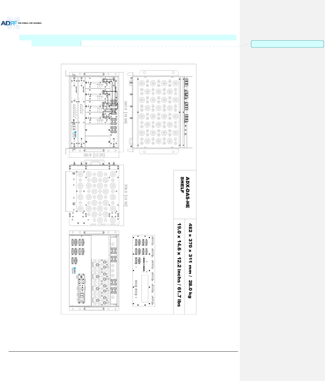
AdvancedRFTechnologies,Inc. 119
NOTE:IndustryCanadaCellularband20dBnominalbandisfromXMHztoYMHzforDownlinkandfromX
MHztoYMHzforUplink.
10. MECHANICALDRAWING
Figure10‐1HEDrawing
메모 [Y29]: Addition14/05/12
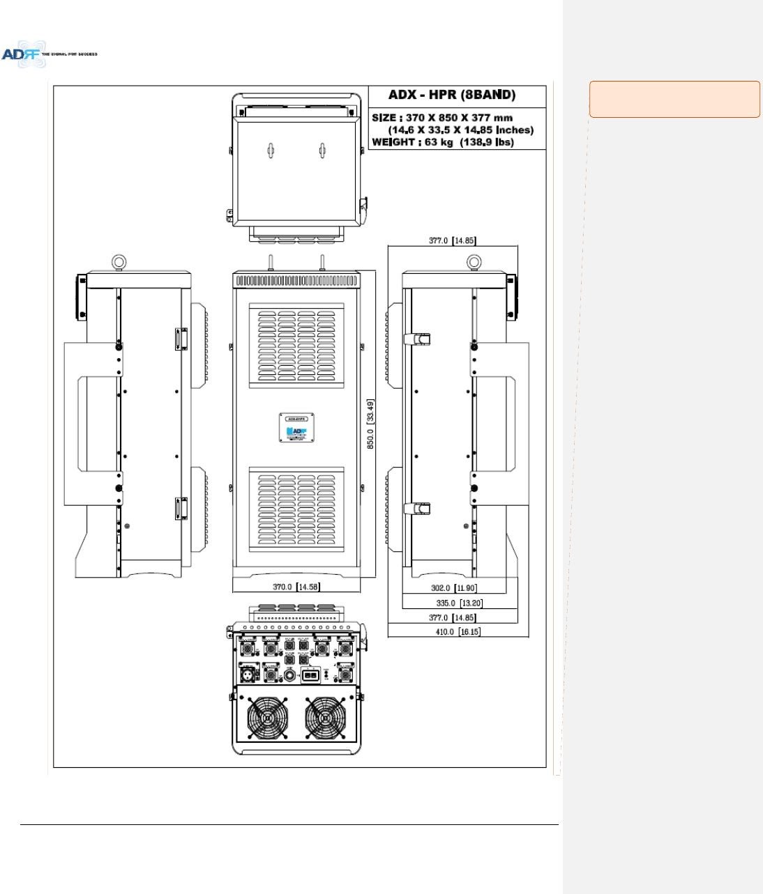
AdvancedRFTechnologies,Inc. 120
Figure10‐2HPRDrawing
메모 [H30]: 6band 로모델명
수정필요함