ASOKA USA PL7667-MST-ETH PlugLine Smart Energy AV Master/Ethernet User Manual PL7667 ETH Users manual 20130913
ASOKA USA Corporation PlugLine Smart Energy AV Master/Ethernet PL7667 ETH Users manual 20130913
Contents
- 1. PL7667-ETH Users manual-20130913
- 2. PL7667-MST Users manual -20130913
PL7667-ETH Users manual-20130913

PlugLine Smart Energy AV Ethernet
66-0366-01Rev.003
User’s Guide
PL7667-ETH
Asoka® User Guide
PlugLink PL7667-ETH
Page 2 of 33
THE SPECIFICATIONS AND INFORMATION REGARDING THE PRODUCTS IN THIS MANUAL ARE
SUBJECT TO CHANGE WITHOUT NOTICE. ALL STATEMENTS, INFORMATION, AND
RECOMMENDATIONS IN THIS MANUAL ARE BELIEVED TO BE ACCURATE BUT ARE PRESENTED
WITHOUT WARRANTY OF ANY KIND, EXPRESSED OR IMPLIED. USERS MUST TAKE FULL RESPONSIBILITY
FOR THEIR APPLICATION OF ANY PRODUCTS.
THE SOFTWARE LICENSE AND LIMITED WARRANTY FOR THE ACCOMPANYING PRODUCT ARE SET
FORTH IN THE INFORMATION PACKET THAT SHIPPED WITH THE PRODUCT AND ARE INCORPORATED
HEREIN BY THIS REFERENCE. IF YOU ARE UNABLE TO LOCATE THE SOFTWARE LICENSE OR LIMITED
WARRANTY, CONTACT YOUR ASOKA REPRESENTATIVE FOR A COPY.
The following information is for FCC compliance of Class A devices: This equipment has been
tested and found to comply with the limits for a Class A digital device, pursuant to part 15 of the
FCC rules. These limits are designed to provide reasonable protection against harmful
interference when the equipment is operated in a commercial environment. This equipment
generates, uses, and can radiate radio-frequency energy and, if not installed and used in
accordance with the instruction manual, may cause harmful interference to radio
communications. Operation of this equipment in a residential area is likely to cause harmful
interference, in which case users will be required to correct the interference at their own
expense.
Modifying the equipment without Asoka’s written authorization may result in the equipment no
longer complying with FCC requirements for Class A digital devices. In that event, your right to
use the equipment may be limited by FCC regulations, and you may be required to correct any
interference or radio or television communications at your own expense.
You can determine whether your equipment is causing interference by turning it off. If the
interference stops, it was probably caused by the Asoka equipment or one of its peripheral
devices. If the equipment causes interference to radio or television reception, try to correct the
interference by using one or more of the following measures:
Turn the television or radio antenna until the interference stops.
Move the equipment to one side or the other of the television or radio.
Move the equipment farther away from the television or radio.
Plug the equipment into an outlet that is on a different circuit from the television or radio.
(That is, make certain the equipment and the television or radio is on circuits controlled by
difference circuit breakers or fuses.)
Modifications to this product not authorized by Asoka could void the FCC approval and negate
your authority to operate the product.
NOTWITHSTANDING ANY OTHER WARRANTY HEREIN, ALL DOCUMENT FILES AND SOFTWARE OF
THESE SUPPLIERS ARE PROVIDED “AS IS” WITH ALL FAULTS. ASOKA DISCLAIM ALL WARRANTIES,
EXPRESSED OR IMPLED, INCLUDING, WITHOUT LIMITATION, THOSE OR MERCHANTABILITY, FITNESS
FOR A PARTICULAR PURPOSE AND NONINFRINGEMENT OR ARISING FROM A COURSE OF DEALING,
USAGE OR TRADE PRACTICE.

Asoka® User Guide
PlugLink PL7667-ETH
Page 3 of 33
IN THE EVENT SHALL ASOKA BE LIABLE FOR ANY INDIRECT, SPECIAL, CONSEQUENTIAL OR
INCIDENTAL DAMAGES, INCLUDING, WITHOUT LIMITATION, LOST PROFITS OR LOSS OR DAMAGE TO
DATA ARISING OUT OF THE USE OF INABILITY TO USE THIS MANUAL, EVEN IF ASOKA HAVE BEEN
ADVISED OF THE POSSIBILITY OF SUCH DAMAGES.
Revision
Date
Description
66-0366-01Rev.003 Sep.2013 Release
Table of Contents
Chapter Title Page
1 Introduction
5
2 Important Safety Instructions for the PlugLink 7
3 Overview 8
4 Installation 11
5 Getting Started with the PlugLink 15
6 Basic PL7667-MST Configuration 19
7 PL7667-MST Administration 22
8
Reset and network of PLC 26
Appendix A
Quick Guide to the PlugLink Default Settings 29
Asoka® User Guide
PlugLink PL7667-ETH
Page 5 of 33
Chapter 1
Audience
This guide is designed as a reference for the networking or computer technician responsible for
installing a PlugLink PL7667-ETH, hereafter referred to as the gateway. It is assumed that you are
familiar with and have a working knowledge of the concepts and terminology associated with
Ethernet and local area networking.
Purpose
This guide describes the hardware and software features of the PlugLink PL7667-ETH. It describes
the physical and performance characteristics of the PL 7667-ETH, explains how to install and
configure the PL7667-ETH, and provides troubleshooting information and specifications.
Conventions
This guide employs the conventions described below to convey instructions and information.
Command descriptions use the following conventions:
Commands and keywords are in italic text.
Arguments for which you supply values are in bold.
Square brackets ([ ]) indicate optional elements.
Braces ({ }) group require choices and vertical bars (|) separate the alternative elements.
Braces and vertical bars within square brackets ([{|}]) indicate a required choice within an
optional element.
Interactive examples use the following conventions:
Terminal sessions and system displays are in normal screen font.
Information to be entered in is in bold text.
Notes, cautions and tips use these conventions and symbols:
Means reader take note. Notes contain helpful suggestions or
references to materials not contained in this manual.
Means reader be careful. In this situation, you might do something that
could result in equipment damage or loss of data.
Means the following will help you solve a problem. The tips information
might not be troubleshooting or even an action, but could be useful
information.
Obtaining Documentation

Asoka® User Guide
PlugLink PL7667-ETH
Page 6 of 33
You can access the most current PlugLink™ documentation on the Asoka website at this URL:
http://www.asokausa.com
Document Feedback
You can submit comments via email to custserv@asokausa.com
You can also submit your comments via regular mail by writing to the following address:
Asoka USA Corporation
Attn: Customer Service,
2620 Augustine Drive Suite 230
Santa Clara, CA 95054 USA
USA
We appreciate your comments.

Asoka® User Guide
PlugLink PL7667-ETH
Page 7 of 33
Chapter 2
Important Safety Instruction for the PlugLink PL7667-ETH
The following precautions should be taken when using this product:
Read all instructions before installing and operating this product.
Do not open the cover on this product and/or alter this product in any way.
Follow common household electrical safety practices.
If you have any questions or concerns regarding these safety measures, please contact
Technical Support at +1 408 550 8167 or email at support@asokausa.com Monday through
Friday from 9:00 am to 5:00 pm PST (excluding holidays.)
Asoka® User Guide
PlugLink PL7667-ETH
Page 8 of 33
Chapter 3
Overview
This chapter provides information about the following topics:
Features
Package Contains
Front Panel Description
Rear Panel Description
Features
PlugLink 7667–ETH features:
Utilizes the existing electrical wiring to distribute data services
IEEE 802.3, 802.3u, 802.3x, 802.3z/ab, 802.1q
One auto-negotiating 10/100BASE-T Ethernet port
Status LEDs showing Ethernet activity and link status
Up to 200Mbps of data transmission
Energy control
Package Contains
Open the package and check that you have all the following items:
1. PlugLink PL7667-ETH
2. 6’ Ethernet cable
3. Warranty and Support Information Card
If any of the parts are incorrect, missing, or damaged, please contact the retailer where you
made your purchase. Keep the carton, including the original packing materials, in case you
need to return the unit for repair.
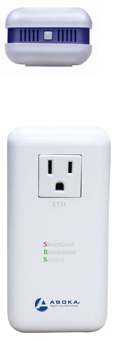
The Top Panel
The top panel of the PL7667 contains one power switch. See Figure 3-1.
Asoka® User Guide
PlugLink PL7667-ETH
Page 9 of 33
Figure 3-1: PL7667-ETH Top Panel
The Front Panel
The front panel of the PL7667 contains the one Power Outlet.
Figure 3-2: PL7667-ETH Front Panel
Asoka® User Guide
PlugLink PL7667-ETH
Page 10 of 33
Side Panel
You can use the status lights to verify connections. Viewed from top to bottom, the table bellow
describes the lights on the side panel of the unit.
Table 3-1: Status Light Descriptons
Power On
Off Device is powered on
Device has no power
PLC Activity Blinking Red
Blinking Yellow
Blinking Green
Off
Low Connection
Good Connection
Excellent Connection
No Connection
ETH Link On
Blinking
Off
Ethernet Connectivity
Ethernet Traffic
No Ethernet Connectivity
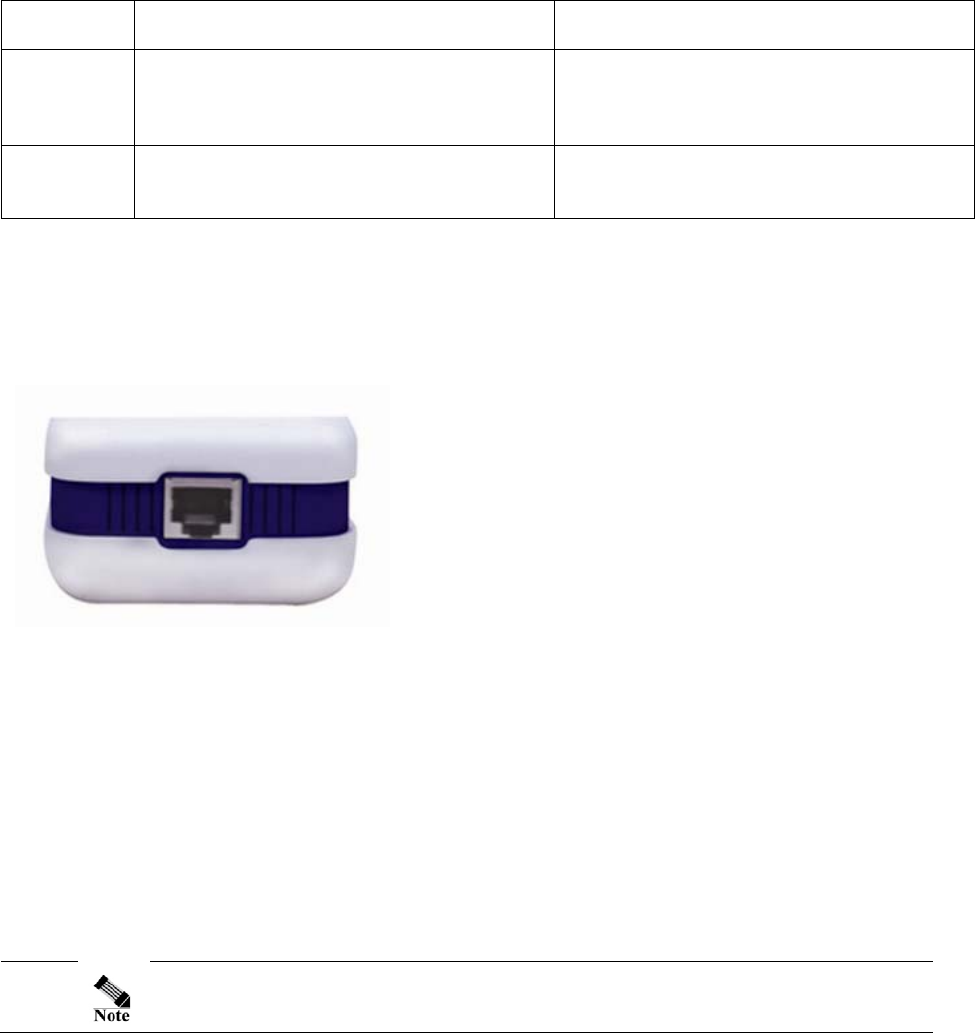
The Bottom Panel
The bottom panel of the PL7667-ETH contains one (1) Ethernet ports as shown below.
Figure 3-2: PL7667-ETH Bottom Panel
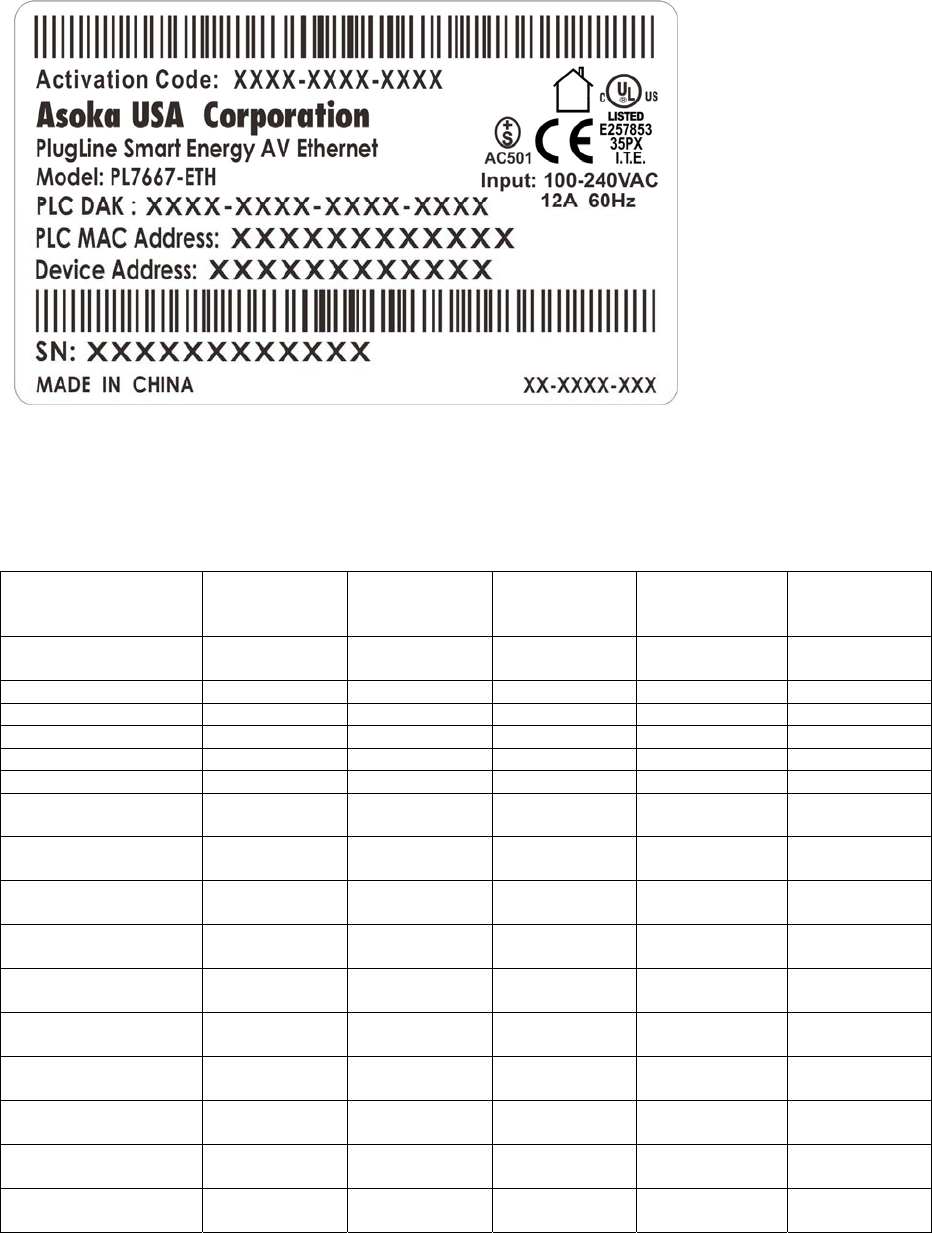
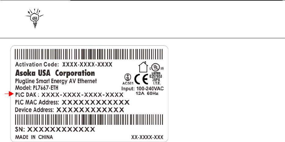
The Rear Panel
The rear panel is where the product label is located. The product label contains the items listed
below.
Model number
Unique device password(PLC DAK)
Powerline MAC Address(PLC MAC)
Ethernet MAC Address
Serial number
For future convenience, please write this information down in your
Warranty Support Information card.
Asoka® User Guide
PlugLink PL7667-ETH
Page 11 of 33
Operating System and Browser Support
You can access the web-based interface by using the operating systems and browsers listed in
Table 3-2.
OS Minimum
Service Pack
or Patch
Microsoft
Internet
Explorer
Mozilla Firefox
Netscape
Communicator Other
Windows 98SE Second
Edition 5.5 or above 1.x or above 7.x + Opera 7 +
Windows ME 5.5 or above 1.x or above 7.x + Opera 7 +
Windows 2000 5.5 or above 1.x or above 7.x + Opera 7 +
Windows XP 5.5 or above 1.x or above 7.x + Opera 7 +
Windows 2003 Server 5.5 or above 1.x or above 7.x + Opera 7 +
Windows NT 4.0 5.5 or above 1.x or above 7.x + Opera 7 +
RedHat 6.2 1.0 7.x + Opera 6
Konqueror 3+
RedHat 7.2 1.0 7.x + Opera 6
Konqueror 3+
Fedora Core 2.0 1.0 7.x + Opera 6
Konqueror 3+
Fedora Core 3.0 1.0 7.x + Opera 6
Konqueror 3+
Fedora Core 4.0 1.0 7.x + Opera 6
Konqueror 3+
Mandriva 10 1.0 7.x + Opera 6
Konqueror 3+
Unix 1.0 7.x + Opera 6
Konqueror 3+
Mac OS X 5.2 1.x 7.x + Opera 7
Safari 1.x +
Mac OS X 1.3x 5.2 1.x 7.x + Opera 7
Safari 1.x +
Mac OS X 10.4.x 5.2 1.x 7.x + Opera 7
Safari 1.x +
Table 3-2: Supported operating systems and browsers

Asoka® User Guide
PlugLink PL7667-ETH
Page 12 of 33
Ensure that your Internet browser popup blocker is disabled. To disable
the popup blocker, follow these steps:
Under Internet Explorer
1. Open a web browser.
2. Under the Tools menu, select Turn off Popup Blocker.
Under Firefox or Netscape
1. Open a web browser.
2. Under the Tools menu, select Options.
3. Choose the Content icon.
4. Uncheck the box next to Block Popup Windows.
5. Click OK
Asoka® User Guide
PlugLink PL7667-ETH
Page 13 of 33
Chapter 4
Installation
This chapter describes how to install your CPE device and how to interpret the LEDs to ensure
proper operation. Read the topics, and perform the procedures in the following order:
Preparing for Installation
Warnings
Safety Instructions
Installing the CPE
Connecting to a 10/100 Port
Wall mounting the CPE
Preparing for Installation
If you mount the CPE to a power outlet, use the screws supplied with the
CPE.
There are no serviceable parts inside the unit. Removing the screws,
cover, or otherwise dismantling the unit voids the warranty.
Warnings
Only trained and qualified personnel should be allowed to install or replace this equipment.
Read the installation instructions before you connect the system to its power source.
Before working on the equipment that is connected to power lines, remove all jewelry
(including rings, necklaces, and watches). Metal objects will heat up when connected to
power and ground and can cause serious burns or weld the metal object to the terminals.
The plug-socket combination must be accessible at all times because it serves as the main
disconnecting device.
To prevent the system from overheating, do not operate it in an area that exceeds the
maximum recommended ambient temperature of 104ºF (40ªC).
Asoka® User Guide
PlugLink PL7667-ETH
Page 14 of 33
This product relies on the building’s installation for short-circuit (over current) protection.
Ensure that a fuse or circuit breaker no larger than 120 VAC, 15A U.S. (240 VAC, 10A
International) is used on the phase conductors (all current-carrying conductors).
A voltage mismatch can cause equipment damage and may pose a fire hazard. If the
voltage indicated on the label is different from the power outlet voltage, do not connect the
device to that receptacle.
Do not work on the system or connect or disconnect cables during periods of lightning
activity.
Ultimate disposal of this product should be handled according to all national laws and
regulations.
Safety Instructions
Read these safety instructions carefully.
Read all cautions and warnings on the equipment.
Plug this equipment directly into a power outlet. No power strips and no extension cords.
Make sure the equipment is connected to the right voltage.
For pluggable equipment, the socket-outlet must be installed near the equipment and must
be accessible.
Place the Ethernet cord where people cannot step on it. Do not place anything over the
Ethernet cord.
Disconnect this equipment from the power outlet before cleaning it. Do not use liquid or
sprayed detergent for cleaning. Use moisture sheet or cloth for cleaning.
Keep this equipment from excessive humidity.
The openings on the enclosure are for air convection and protect the equipment from
overheating. Do not cover the openings.
If the equipment will not be used for a long period of time, disconnect the equipment from
the power outlet to avoid any damage from transient over-voltage.
Do not pour any liquid into opening. This could cause fire or electrical shock.
Do not open the equipment casing. For safety reasons, the equipment should only be
opened by qualified service personnel.
Have the equipment checked by a service professional if one of the following situations
arises:
• The plug is damaged.
• Liquid has entered the equipment.
• The equipment has been exposed to moisture.
• The equipment does not work properly, or you cannot get it to work according to
user’s manual.
• The equipment has been dropped or damaged.
• The equipment has obvious signs of breakage.
• Do not leave this equipment in an unconditioned environment. Temperatures above
45ªC (113ªF) can damage the equipment.
• Keep this guide for later reference.
Installing the CPE
Asoka® User Guide
PlugLink PL7667-ETH
Page 15 of 33
You can install the CPE simply by plugging directly into a power outlet or by physically mounting
onto a power outlet. Before you begin the installation, decide how you want to install the CPE
by reviewing the illustrations in these sections:
Installing the CPE directly to a power outlet (without mounting screws and brackets)
Installing the CPE directly to a power outlet (without mounting screws and brackets)
The CPE can be simply plugged in directly to a power outlet. If you do not wish to physically
mount the CPE onto the power outlet, follow these steps:
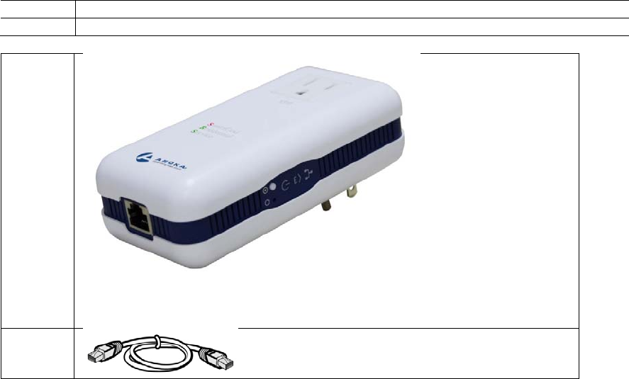
Take out what you need by removing the items shown in Figure 1-1 from the shipping
container:
1 PlugLink PL 7667-ETH
2 6’ Ethernet Cable
1⇒
2⇒
Figure 4-1: PlugLink PL 7667-ETH, Ethernet Cable
Connect the CPE into a nearby wall outlet
Connect the enclosed Ethernet cable to the Ethernet port of the unit
Connect the opposite end of the cable to an Ethernet port on the PC or laptop
Asoka® User Guide
PlugLink PL7667-ETH
Page 16 of 33
Chapter 5
Getting Started with the PL7667-ETH
This chapter provides a quick step-by-step installation and setup procedure guide for a
standalone PL 7667-ETH.
For detailed installation procedures for mounting your CPE, see Chapter 4, “Installation.” For
product overview information, see Chapter 3, “Overview.”
Connecting to a PC
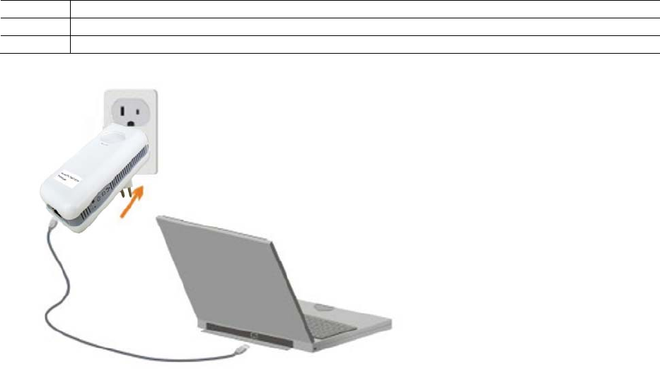
To perform the initial configuration, follow these steps:
1. Connect a Category-5 straight-through cable to the 10/100 ports on the PL7667.
2. Connect the other end of the cable to an Ethernet (RJ-45) port on the workstation, PC, or
server.
3. Plug the PL7667 directly into an outlet.
1 PlugLink PL 7667-ETH
2 Ethernet cable
3 Power outlet
Figure 5-1: Connecting to a LAN port.
Asoka® User Guide
PlugLink PL7667-ETH
Page 17 of 33
Assigning your PC to the same network as the CPE
The –PL 7667 has an IP address: 192.168.1.254.
For network access, you must manually assign your PC an IP address of 192.168.1.x, where “x” is
a number between 1 and 254(excluding 253.)
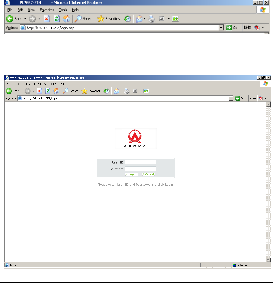
Accessing the CPE from your Browser
1. Open an Internet browser (i.e. Internet Explorer or Mozilla Firefox).
2. In the address field, type 192.168.1.254 and press Enter.
Figure 5-2: Address field.
3. In the User ID field, type admin.
4. In the Password field, type welcome.
5. Click Login.
Figure 5-3: Login screen
Asoka® User Guide
PlugLink PL7667-ETH
Page 18 of 33
The username and password are case sensitive.
For security, you should set a unique system password after initial login.
For instructions on how to set a unique system password, see Chapter 7.
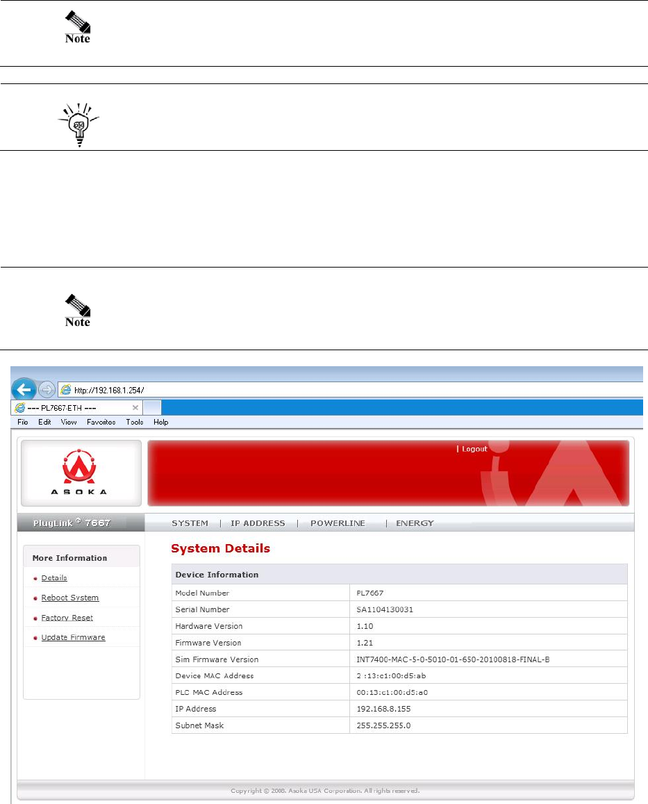
Understanding the PL7667-ETH Web Interface
When you access the web-based user interface (UI), the System Details page is the first page
you will see. The System Details page shows you a quick view of the adapter’s status and settings.
All setup pages can be reached from this page.
The System Details page is also the Home Page of the adapter’s web
interface.
Figure 5-4: System Details Page (Home page)
1. Quick Main Navigation Links
Asoka® User Guide
PlugLink PL7667-ETH
Page 19 of 33
The UI is divided into five main logical sections and you can be directed to any of the five
sections by clicking on their corresponding links.
2. Quick Sub Navigation Links
In each of the five main logical sections, sub navigation links on the right will appear,
providing you with logical links for each specific category.
3. Quick Buttons
1) The Home button is available in every page of the UI. Pressing this button will take you
back to the home page, which is the System Details page.
2) The Glossary button is available in every page of the UI. Pressing this button will take you
to a glossary page that defines many of the technical terms used in this UI.
3) The Help button is available in every page of the UI. Pressing this button will take you to a
help page that provides detailed explanations and steps on configuring your gateway.
4) The Logout button is available in every page of the UI. Pressing this button will enable you
to log out of the gateway.
4. Detail Information
Displays detailed information about the gateway that includes: model number, firmware
version number, hardware version, serial number, Local Area Network (LAN) settings
5. Page Name
The page you are on is identified by its Page Name.
Asoka® User Guide
PlugLink PL7667-ETH
Page 20 of 33
Chapter 6
Basic PL7667–ETH Configuration
This chapter presents procedures for configuring the basic parameters of your PL7667 interface,
including IP, Subnet Mask and DNS settings.
This chapter contains the following sections:
LAN Settings
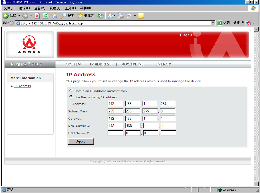
Configuring your LAN Settings
To configure the CPE’s LAN settings, click IP ADDRESS on the Main menu. The IP ADDRESS
Configuration Page is the first page under the IP ADDRESS section.
Figure 6-1: IP ADDRESS Configuration Screen
Asoka® User Guide
PlugLink PL7667-ETH
Page 21 of 33
1. IP Address
The IP Address is the internal IP address of the PL7667. The default IP address is 192.168.1.254.
To access the PL7667 Setup Interface, type this IP address into the address or navigation bar
of your web browser. This address can be changed if needed. To change the IP address,
type in the new IP address and click Apply.
The IP address you choose should be a non-routable IP. Examples of a
non-routable IP are:
192.168.x.x (where x is anything between 0 and 255)
10.x.x.x (where x is anything between 0 and 255)
2. Subnet Mask
A Subnet Mask allows you to break down what appears (logically) to be a single large
network into smaller ones, which reduces network overhead.
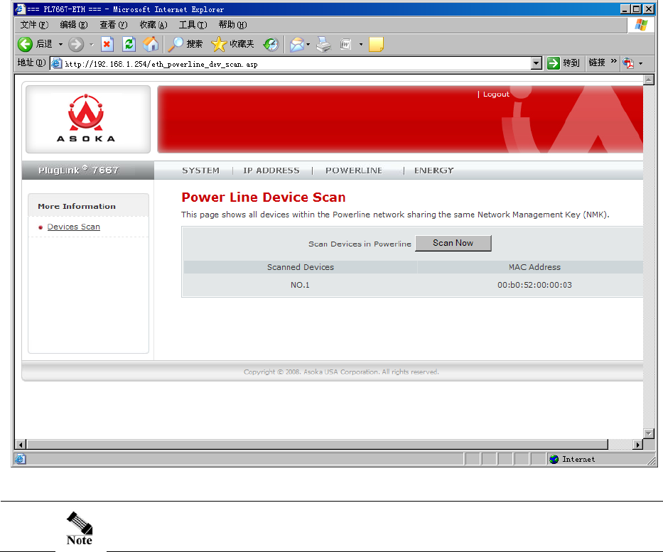
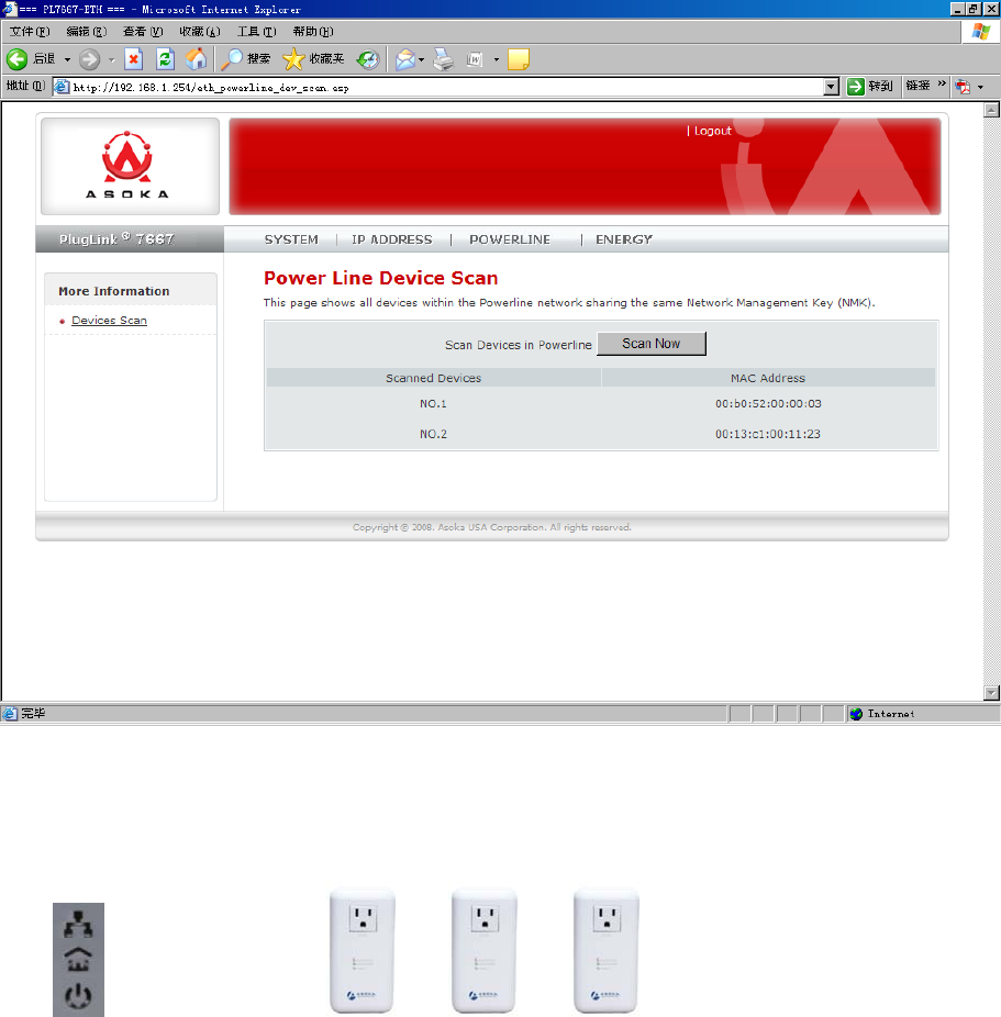
Powerline
The PL7667-ETH allows you to configure the Powerline network encryption key to talk to other
Powerline devices on your network.
To scan and view a list of Powerline devices on your network, simply go to POWERLINE in the
main menu and select Device Scan in the sub menu.
Asoka® User Guide
PlugLink PL7667-ETH
Page 22 of 33
Figure 6-2: Device Scan Screen
The Device Scan screen will only list Powerline devices on your network
that have the same Powerline Network Encryption KEY (NEK).

Asoka® User Guide
PlugLink PL7667-ETH
Page 23 of 33
Chapter 7
PL7667–ETH Administration
This chapter describes how to perform operations to administer your PL7667-ETH. This chapter
consists of the following sections:
Reboot
Restoring Factory Default
Firmware upgrade
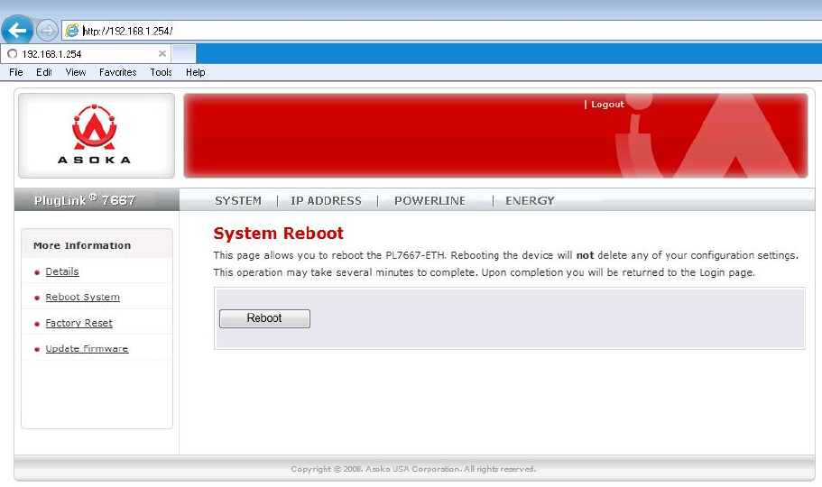
Reboot
Sometimes it may be necessary to reboot the adapter if it is working improperly. Rebooting will
not delete any of your configuration settings. To reboot the adapter:
1. Click on Systems in the Main menu.
2. In the Sub menu, select Reboot System.
3. Click Reboot.
4. A popup window will appear to confirm your request to reboot the adapter. Click OK to
continue.
5. After a minute, the home page of the adapter will reappear automatically. If not, type the
adapter’s IP address (default = 192.168.1.254) into the address or navigation bar of your web
browser.
It is important not to turn off the power or unplug the adapter (CPE)
during the reboot.
Asoka® User Guide
PlugLink PL7667-ETH
Page 24 of 33
Figure 7-1: Reboot screen
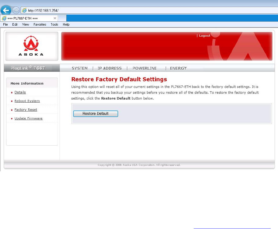
Restoring Factory Defaults
At times, you may need to restore factory default settings on the adapter. It is recommended
that you back up your settings prior to restoring to factory default settings. To restore factory
default settings:
1. Click on Systems in the Main menu.
2. On the Sub menu, select Factory Reset.
6. Click Restore Default.
7. A popup window will appear to confirm your request to reboot the adapter. Click OK to
continue.
8. After a minute, the home page of the adapter will reappear automatically. If not, type the
adapter’s IP address (default = 192.168.1.254) into the address or navigation bar of your web
browser.
Asoka® User Guide
PlugLink PL7667-ETH
Page 25 of 33
Figure 7-2: Restoring Factory Default screen
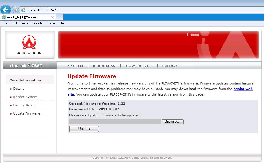
Update Firmware
Firmware updates will be made available periodically from Asoka. Firmware updates contain
feature improvements and fixes to problems that may have existed. When Asoka releases new
firmware, you can download the firmware from Asoka’s web site at http://www.asokausa.com
and update your adapter’s firmware to the latest version.
To upload a new firmware upgrade onto the CPE, follow these steps.
1. Click on Systems in the Main menu.
2. In the Sub menu, select Update Firmware.
3. Click Browse to locate the new firmware update file downloaded from Asoka’s web site.
4. The box next to the Browse button will now display the location and name of the firmware
file you just selected. Click Update.
5. You will be asked if you are sure you want to continue. Click OK.
6. You will see one more message. This message tells you that the CPE may not respond for up
to one minute as the firmware is loaded into the adapter and it is rebooted. Click OK.
7. When the firmware upgrade is complete, the adapter home page should appear
automatically. If not, type in the CPE’s address (default – 192.168.1.254) into the address or
navigation bar of your web browser.
Asoka® User Guide
PlugLink PL7667-ETH
Page 26 of 33
Figure 7-3: Firmware upgrade screen.
Asoka® User Guide
PlugLink PL7667-ETH
Page 27 of 33
Chapter 8
Reset and network of PLC
The PL7667-ETH device has two hardware push buttons:
FW RST (Firmware Default Reset ) button – Resets the PL7667-ETH back to factory default settings.
Press and hold the button with a pin or sharp object for about 2 seconds until you see the lights
on the device flash briefly.
SECURITY (Network ID) button – All PL7667-ETH devices have a default password Network
Encryption Key (NEK) set to “HomePlugAV” allowing them to communicate to each other. The
SECURITY button allows you to set a devices’ password to a randomized Network Encryption
Key (NEK) for maximum security. You can then set other devices to the same NEK by using their
SECURITY button. Only units with the same NEK can communicate to each other.
SETTING A RANDOMIZED NETWORK PASSWORD
1. Select a PL7667-ETH (Device A) and plug into an AC outlet. The POWER light indicator
should be lit solid green.
a. Press the SECURITY button BRIEFLY (1 second) and release. The POWER light should
now be blinking green.
b. IMPORTANT: If the POWER light is not blinking green, repeat Step “a” until the
power light blinks green.
c. This unit is now ready to create a new randomized NEK (Net Encryption Key)
network. This unit will remain in this “adder” mode for about 2 minutes.
2. Select another PL7667-ETH (Device B) and plug into a second outlet.
a. Press the SECURITY button BRIEFLY (1 second) and release. The POWER light should
now be blinking green.
b. IMPORTANT: If the power light is not blinking green, repeat Step “a” until the
power light is blinking green.
3. In about 15 seconds the POWER light will change from flashing green to solid green and
the PLC ACT (Power line Communication Activity) light will turn solid green (flashing
green when there is data traffic) indicating they are synchronized with the same NEK.
4. Congratulations, you are done!
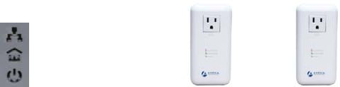
Ethernet
light
PLC ACT
Device A Device B
Asoka® User Guide
PlugLink PL7667-ETH
Page 28 of 33
Figure 8-1: Two devices of PLC
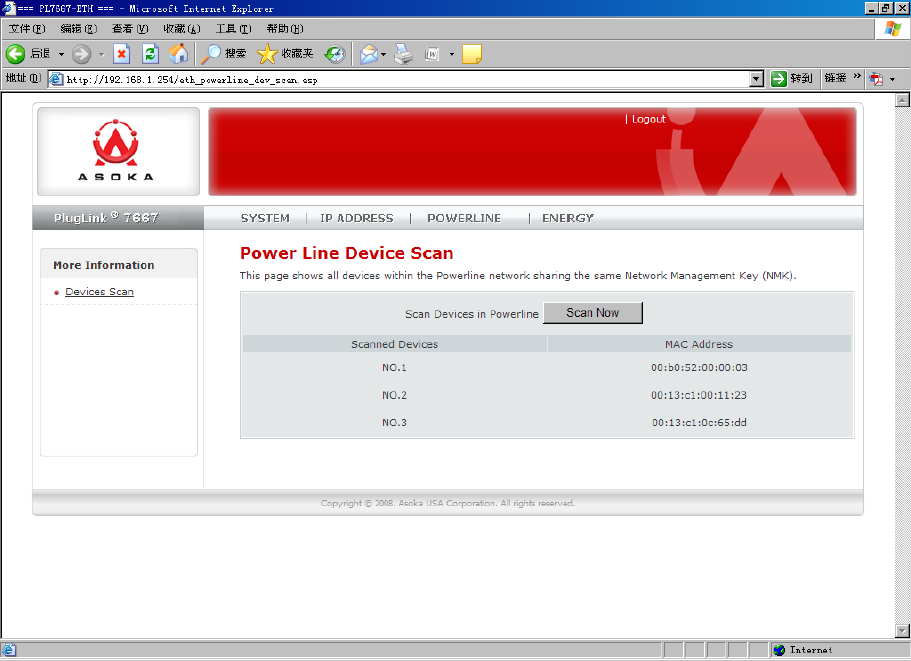
ADDING A THIRD OR MORE PLUGLINK HD AV DEVICES
1. Plug your new PL7667-ETH (Device C) into an AC outlet. The POWER light indicator should
be lit solid green.
a. Press the SECURITY button BRIEFLY (1 second) and release. The POWER light should
now be blinking green.
b. IMPORTANT: If the POWER light is not blinking green, repeat Step “a” until the
power light is blinking green.
c. This unit is now ready to join the existing HD AV network. This unit will remain in this
“adder” mode for about 2 minutes.
2. From your existing devices (either device A or device B) press the SECURITY button
BRIEFLY (1 second) then release. The POWER light should now be blinking green.
d. IMPORTANT: If the power light is not blinking green, repeat Step “2” until the
power light is blinking green.
Device A Device B Device C
Ethernet
light
PLC ACT
Asoka® User Guide
PlugLink PL7667-ETH
Page 29 of 33
3. In about 15 seconds the POWER light will change from flashing green to solid green and
the PLC ACT (Power line Communication Activity) light will turn solid green (flashing green
when there is data traffic) indicating they are synchronized with the same NEK.
4. To add more PlugLink devices; simple repeat this process per device.
5. Congratulations, you are done!
Figure 8-2: Three devices of PLC
Notes:
1. The other devices already in the Power line network with the proper NEK are not
affected and do not need to be reconfigured.
2. If you disconnect power from any device, its NEK value will remain and will not default
back to “HomePlugAV” NEK.
3. An adapter can only generate a private key once. To replace a private key, first reset
the unit back to its factory defaults by pressing the Firmware Default Reset (FW RST)
button for 1 second, then follow the procedure above.

30 of 20
Appendix A
Default Settings
Login and Password:
User Name: admin
Password: welcome
IP Setting:
IP Address: 192.168.1.254
Subnet Mask 255.255.255.0

31 of 20
FCC Notice
FCC Statement
This equipment has been tested and found to comply with the limits for a Class B digital device,
pursuant to part 15 of FCC Rules. These limits are designed to provide reasonable protection against
harmful interference in a residential installation. This equipment generates and can radiate radio
frequency energy and, if not installed and used in accordance with the instructions, may cause
harmful interference to radio communications. However, there is no guarantee that interference will
not occur in a particular installation. If this equipment does cause harmful interference to radio or
television reception, which can be determined by turning the equipment off and on, the user is
encouraged to try to correct
The interference by one or more of the following measures:
Reorient or relocate the receiving antenna.
Increase the separation between the equipment and receiver.
Connect the equipment into an outlet on a circuit different from that to which the receiver is
connected.
Consult the dealer or an experienced radio/TV technician for help
This device complies with Part 15 of FCC Rules.
Operation is subject to the following two conditions:
This device may not cause harmful interference, and
This device must accept any interference received, including interference that may cause undesired
operation
FCC RF Radiation Exposure Statement
Note: The manufacturer is not responsible for any radio or TV interference caused by
unauthorized modifications to this equipment. such modifications could void the user’s authority to
operate this equipme.
Asoka USA Corporation
2620 Augustine Drive Suite 230
Santa Clara, CA 95054 USA
Phone: (408) 550–8167
Fax: (408) 884–2390
www.asokausa.com
URL: www.asokatech.com