ASSALOY YRHCPZB0 Yale Real Living Electronic Zigbee Lock User Manual 12 0001 Exhibit Cover
ASSA ABLOY Inc. Yale Real Living Electronic Zigbee Lock 12 0001 Exhibit Cover
ASSALOY >
Contents
- 1. User Manual
- 2. Manual - YRD210-ZB
- 3. Manual - YRD220-ZB
- 4. Manual - YRT210-ZB
- 5. Manual - YRT220-ZB
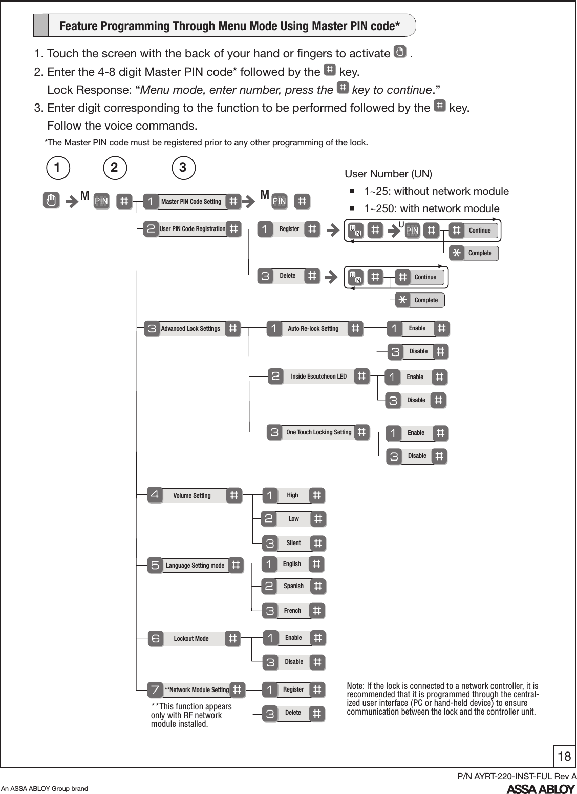
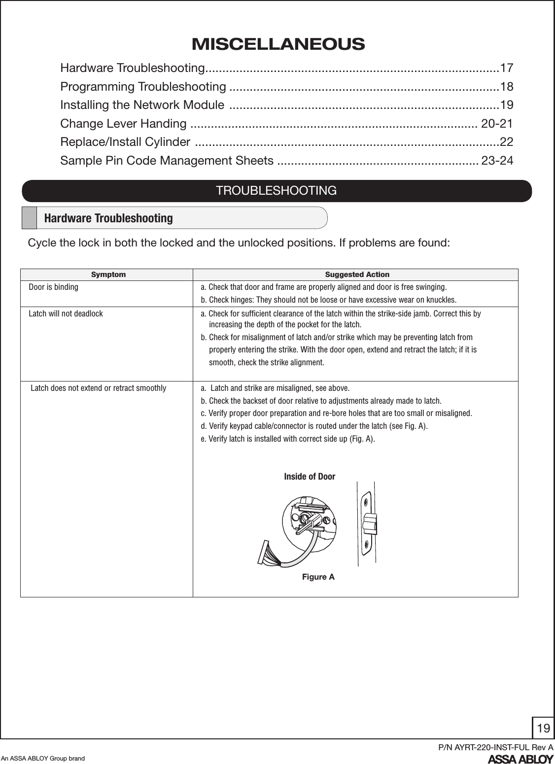
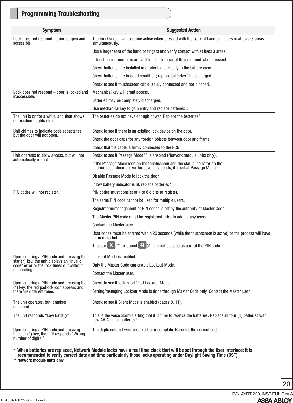
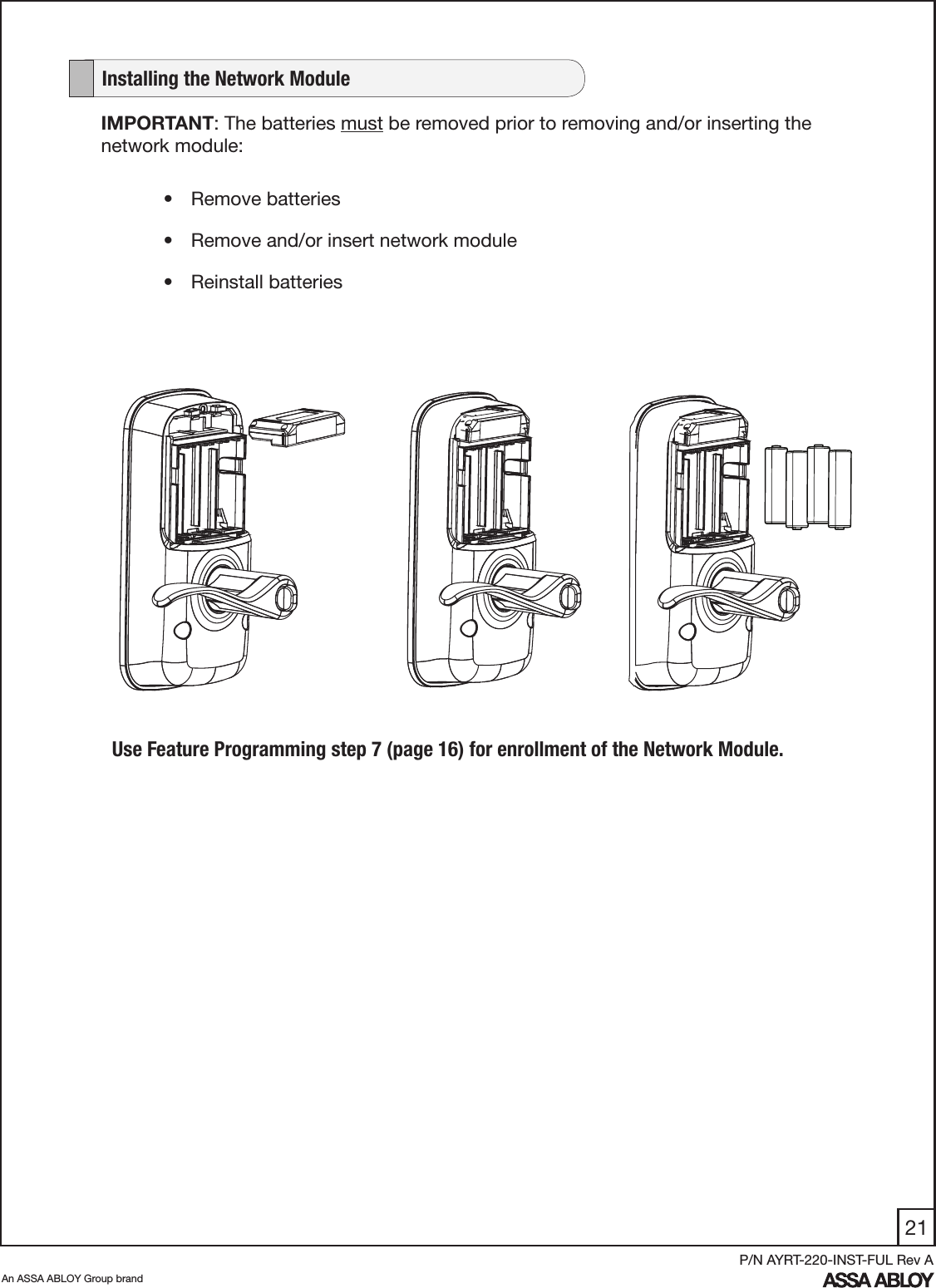
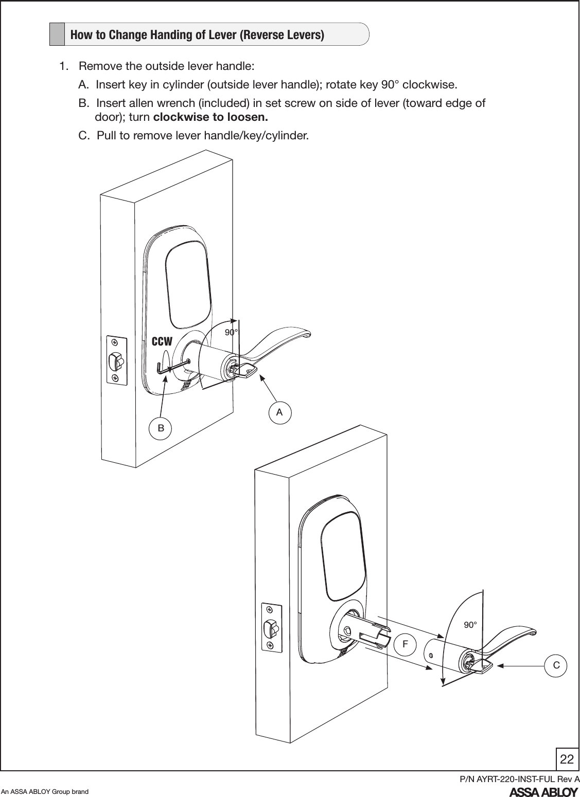
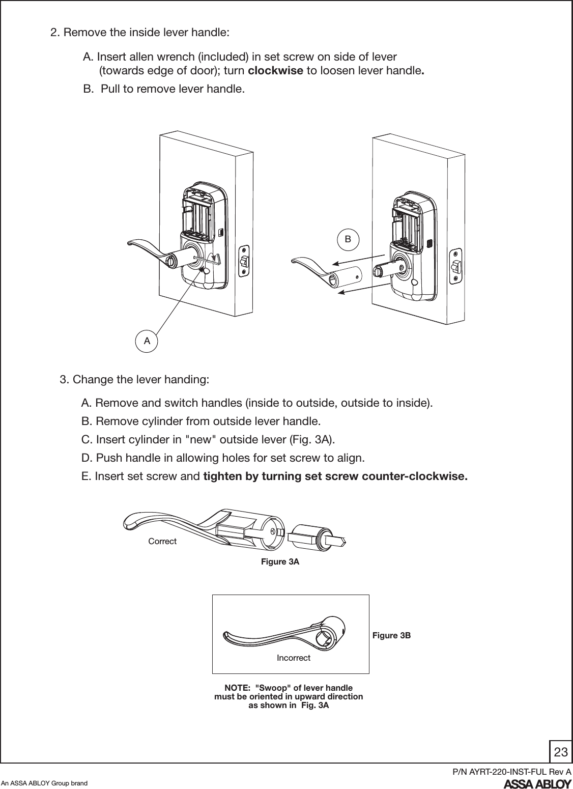
Manual - YRT220-ZB

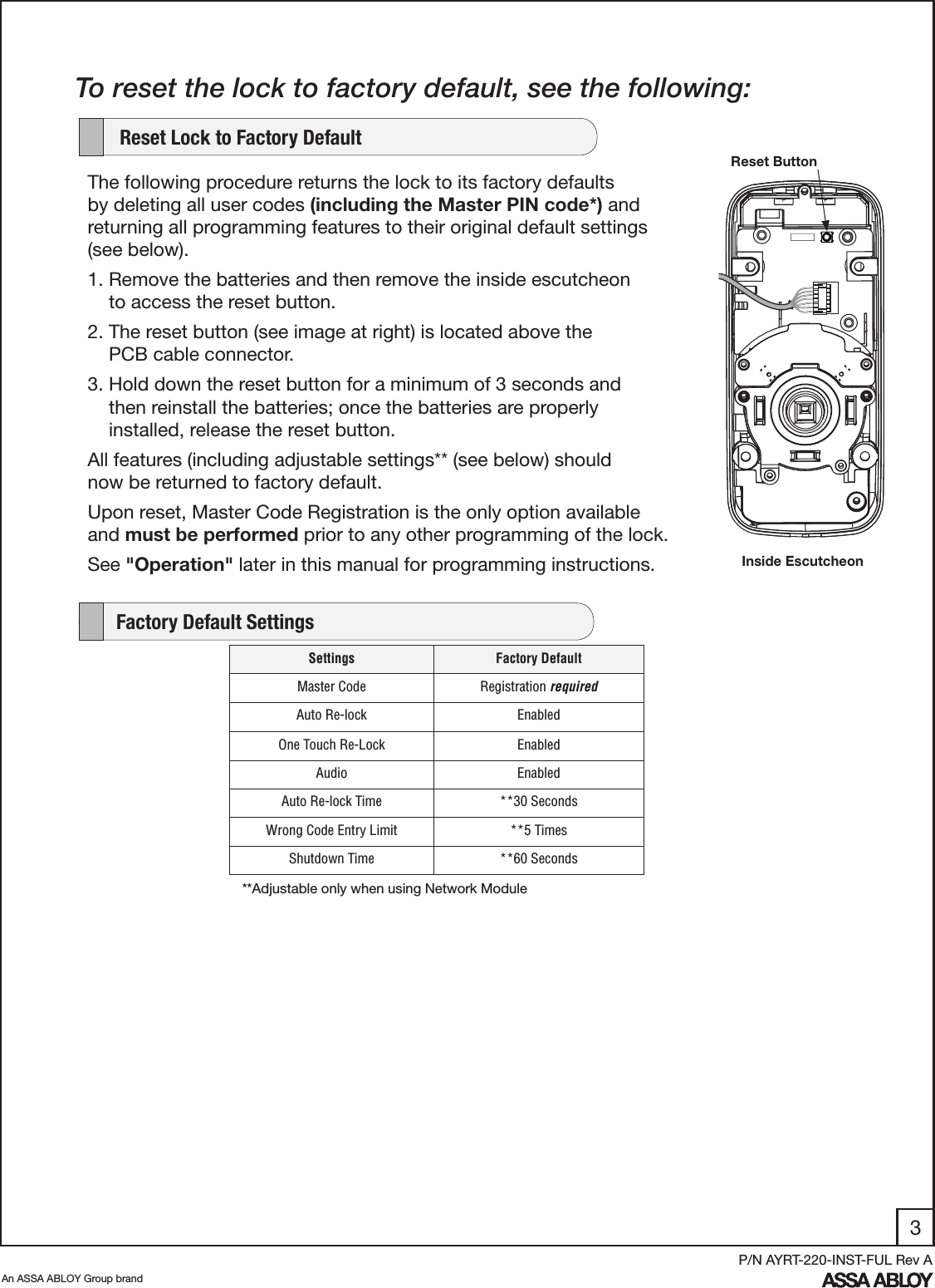

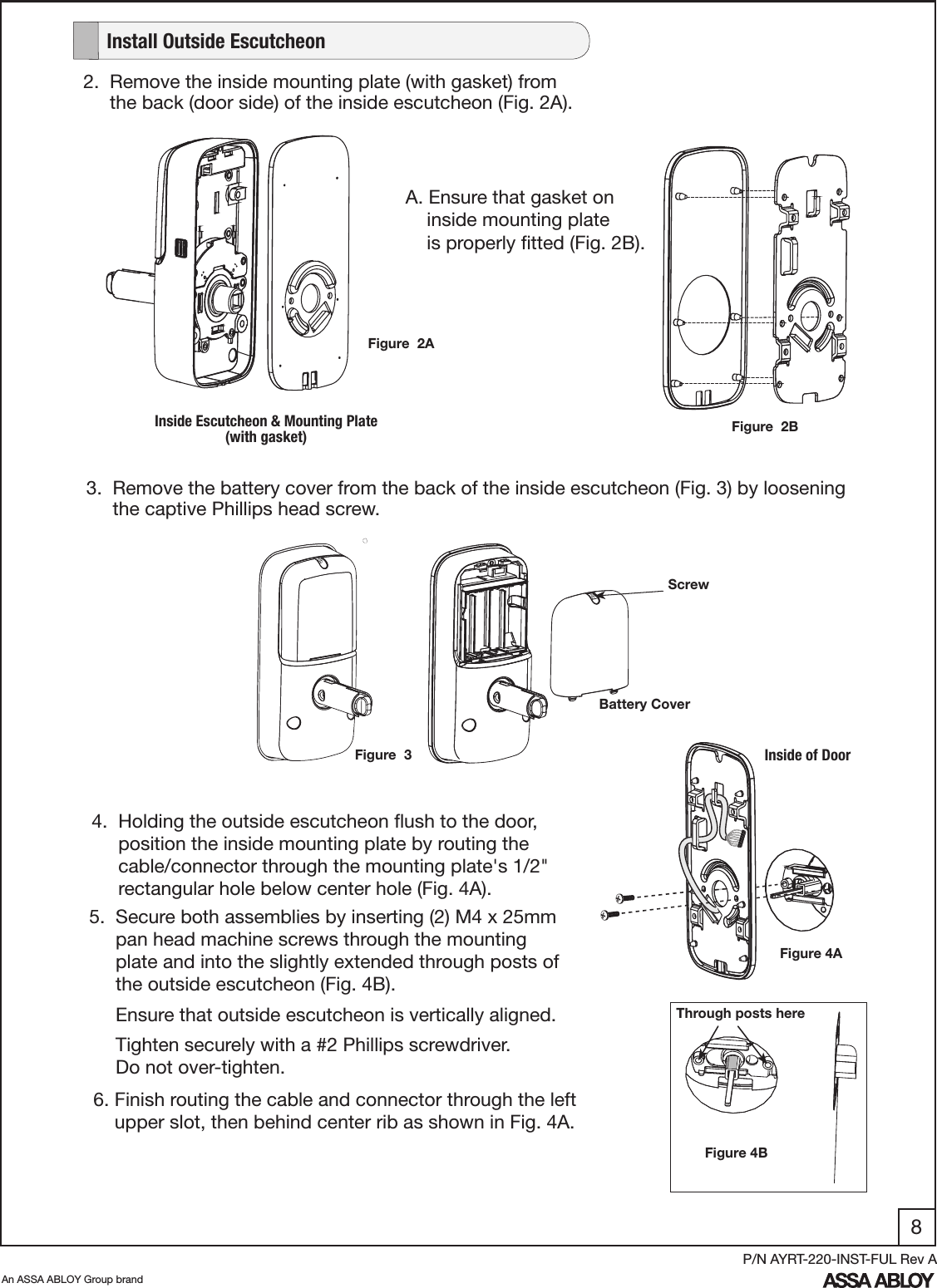
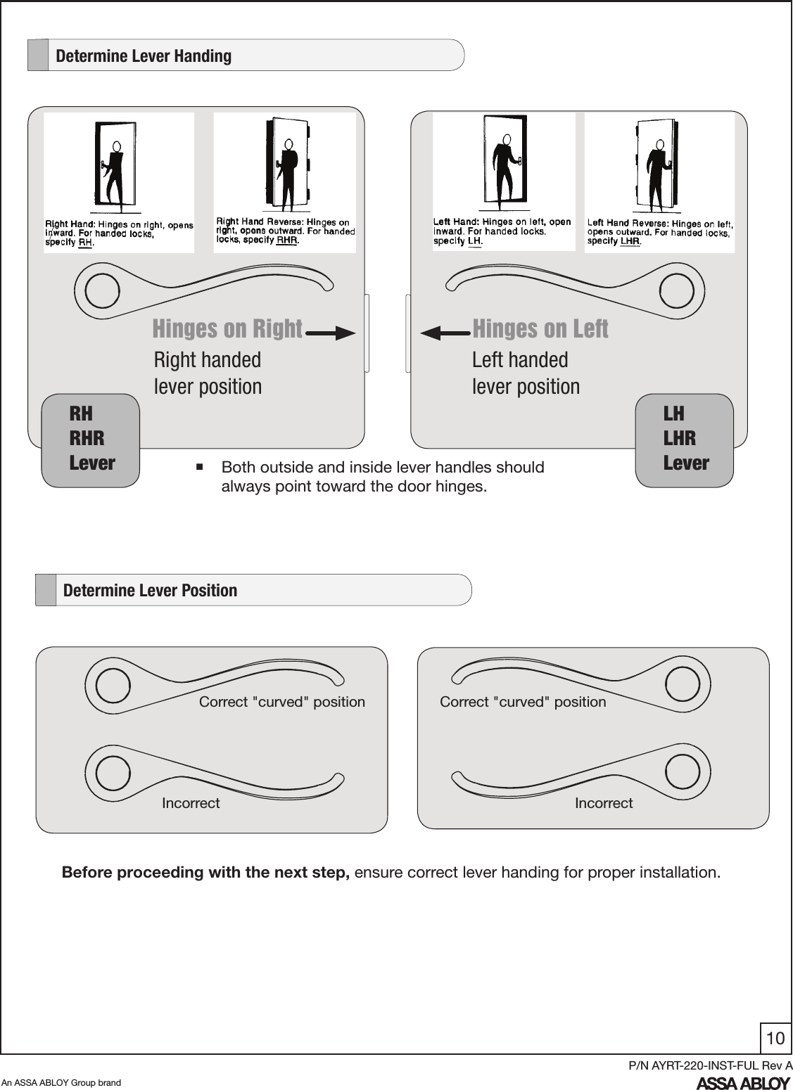
![9An ASSA ABLOY Group brandP/N AYRT-220-INST-FUL Rev A7. Attach cable assembly to the inside escutcheon printed circuit board (PCB) by lining up notches on top of cable connector to slots on PCB connector (Fig. 7A & 7B). Press connector in firmly using thumbs until completely seated (properly seated position indicated by arrows on PCB as in Fig. 7B). 8. Install and secure inside escutcheon to inside mounting plate using (4) M4 x 8mm [8-32 x 5/16"] pan head machine screws through the inside escutcheon into the mounting plate (Fig. 8). NOTE: Make sure cable does not obstruct path of the mounting screws.Inside EscutcheonReset ButtonFigure 7BFigure 7ACable ConnectorFigure 8](https://usermanual.wiki/ASSALOY/YRHCPZB0.Manual-YRT220-ZB/User-Guide-1641561-Page-10.png)