Accurate Locators 2GHZANT ZOND 12 2GHz Ground Penetrating Antenna User Manual Part 1
Accurate Locators Inc. ZOND 12 2GHz Ground Penetrating Antenna Part 1
Contents
- 1. Part 1
- 2. Part 2
Part 1

RAD~
"Zond-12es'
PhonelFax (+371)-7141041
E-mail:radsys@radsys.lv
www.radsys.1~
Systems,
Inc.
Georadar
USER'S MANUAL
Riga,
2007
Lomonosova Str. 1, B
-
406, Riga LV
-
1019, Latvia
Web:
FCC Notice (for U.S. Customers):
This device complies with part 15 of the FCC Rules:
Operation is subject to the following conditions:
1. This device many not cause harmful interference, and
2. This device must accept any interference received, including interference that may cause
undesired operation
Warning: Changes or modifications to this unit not expressly approved by the party responsible
for compliance could void the user’s authority to operate the equipment.
Operation of this device is restricted to law enforcement, fire and rescue officials, scientific
research institutes, commercial mining companies, and construction companies. Operation by
any other party is a violation of 47 U.S.C. § 301 and could subject the operator to serious legal
penalties.
Coordination Requirements.
(a) UWB imaging systems require coordination through the FCC before the equipment may be
used. The operator shall comply with any constraints on equipment usage resulting from this
coordination.
(b) The users of UWB imaging devices shall supply detailed operational areas to the FCC Office
of Engineering and Technology who shall coordinate this information with the Federal
Government through the National Telecommunications and Information Administration. The
information provided by the UWB operator shall include the name, address and other pertinent
contact information of the user, the desired geographical area of operation, and the FCC ID
number and other nomenclature of the UWB device. This material shall be submitted to the
following address:
Frequency Coordination Branch., OET
Federal Communications Commission
445 12th Street, SW
Washington, D.C. 20554
ATTN: UWB Coordination
(d) Users of authorized, coordinated UWB systems may transfer them to other qualified users
and to different locations upon coordination of change of ownership or location to the FCC and
coordination with existing authorized operations.
(e) The NTIA/FCC coordination report shall include any needed constraints that apply to day-to-
day operations. Such constraints could specify prohibited areas of operations or areas located
near authorized radio stations for which additional coordination is required before operation of
the UWB equipment. If additional local coordination is required, a local coordination contact
will be provided.
(f) The coordination of routine UWB operations shall not take longer than 15 business days from
the receipt of the coordination request by NTIA. Special temporary operations may be handled
with an expedited turn-around time when circumstances warrant. The operation of UWB
systems in emergency situations involving the safety of life or property may occur without
coordination provided a notification procedure, similar to that contained in CFR47 Section
2.405(a)-(e), is followed by the UWB equipment user.
"Zond-12e"
"Zond-12e"
Fig.14.
Fig.1. 38-75-
Fig.la).
"Zond-12e" IBM-
1 1 1
10/100BaseT. TCPIIP
10,5
"Zond-12e".
GHz GHz
1.
INTRODUCTION
1.1.
Purpose and the Field of Application.
The georadar is the facilities for subsurface profiling purposed to obtain
continuous profiles of subsurface structure of ground along the survey line.
The principal fields of application are:
mapping of the surface of bed
-
rock under the layer of mellow deposits;
search of pipes and cables;
glaciology;
archeology and criminal law;
search of cavities in;
mapping of water table in sand deposits;
mapping of bottom and bottom deposits of fresh water reservoirs;
mapping of river paleobeds;
searching of sites of burring of industrial wastes, etc.
1.2.
General Description.
The georadar in operating condition consists of four units: the control unit, the
Notebook computer, the antenna and the battery (see Fig 1). The computer is mounted on the
special platform on top of the control unit. They are connected by the cable with pin
specification shown on The control unit is operated by direct current of voltage12
V
supplied by the battery or a regulated rectifier. The antenna and the control unit are connected
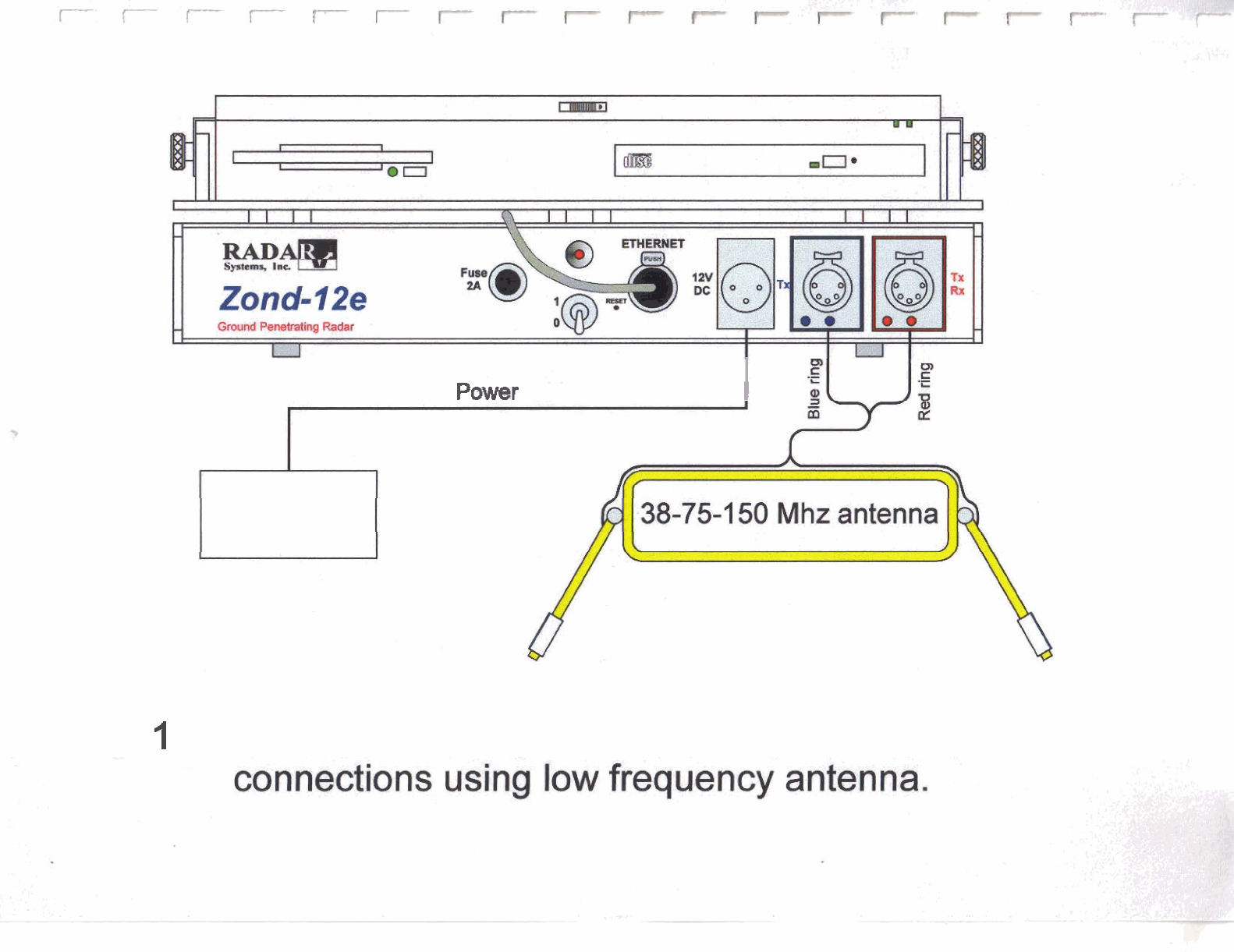
by the antenna cable as it is shown on If antenna has two connectors (antenna
150 MHz) they are marked with red and blue labels (see Using of two separated
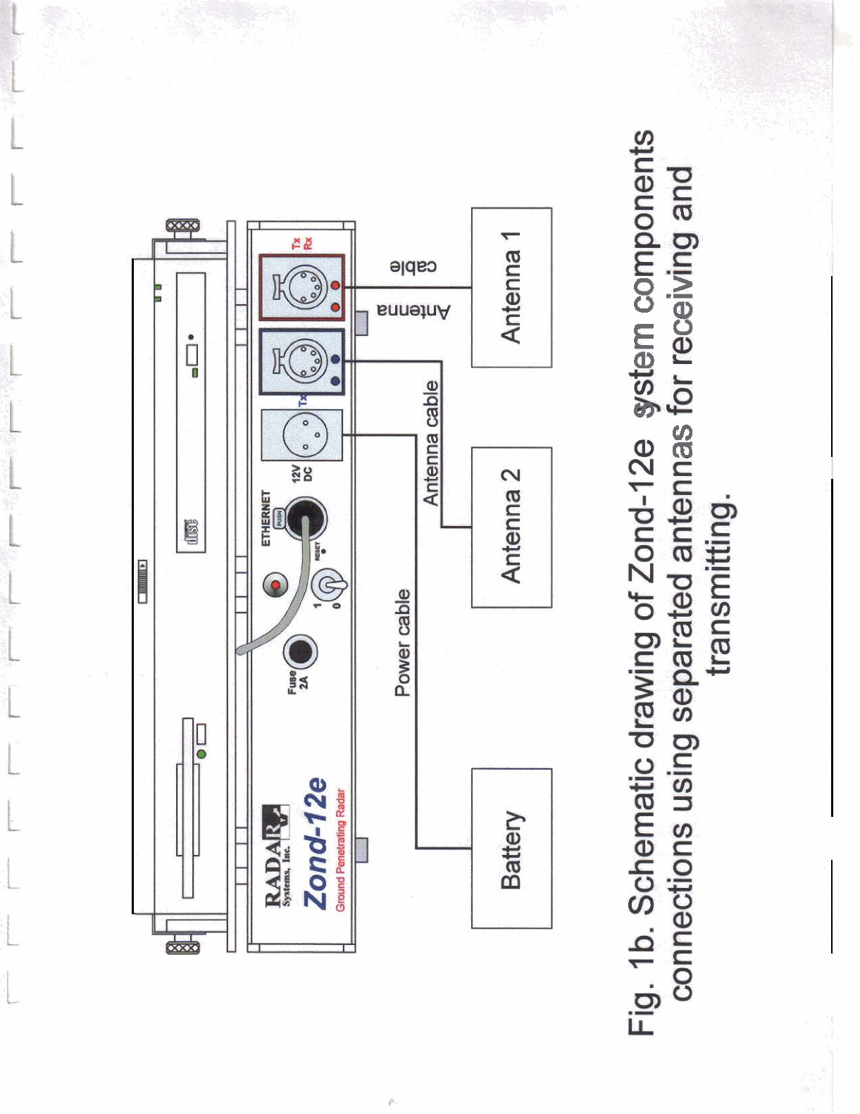
antennas for transmitting and receiving are shown on Fig. lb where transmitting antenna is
connected to blue connector but receiving antenna to red one. Description of controls and
connectors of Control Unit is on Fig.2. Hereafter are presented brief specifications of different
units of the georadar.
Computer.
There can be applied in composition of the georadar any
compatible Notebook computer operating in Windows 98 2000 Me XP, equipped with
Ethernet card Information exchange between the computer and the control unit
is performed according to protocol
as
between two peer network elements. The
computer performs the following functions: control of operational modes of the georadar,
data acquisition, processing and displaying.
Battery.
Any power supply providing direct current voltage from to 13
V
at current up
to 0.8 A. Upon delivery the georadar is supplied with the sealed lead battery with voltage 12
V
of capacity 7 Ah, the power cord, and the automatic charger.
Control unit.
The circuit diagram of the control unit is shown in Fig.2. Brief description of
controls of the control unit is presented on page
9.
Packaging of the unit is shown in Fig. 13.
Antenna.
Antennas of three types are applied in the georadar High frequency
shielded antennas 100, 300, 500, 900 MHz, 1.5 and unshielded 2 antenna are

similar and differ only in dimensions. Theese antennas are intended for operating mostly in
contact with the groung. The low frequency antenna 38-75
-
150 MHz is of the dipole type
with replaced dipoles for operation at frequencies 150, 75 and 38 MHz. That antenna may be
used in isolation from the ground at distance 0.15
-
0.4 m as well as in contact. Shielded air-
coupled 750 MHz antenna operates only in isolation from the ground at distance 0.2-0.3 m.
2.
PREPARING OF THE GEORADAR TO OPERATION.
2.1.
Connection of units.
Before to begin to make any connections and switching on please read thoroughly the
instructions below and strictly follow them when connecting units of the georadar. The
connection diagram of units is shown in Fig. 1, 1 a and 1 b.
Warning! Before connection of any cable to the Control Unit make sure that it is turned
OFF.
It is strongly prohibited to connect or disconnect any cables to the Control Unit or
antenna while the Control Unit is powered.
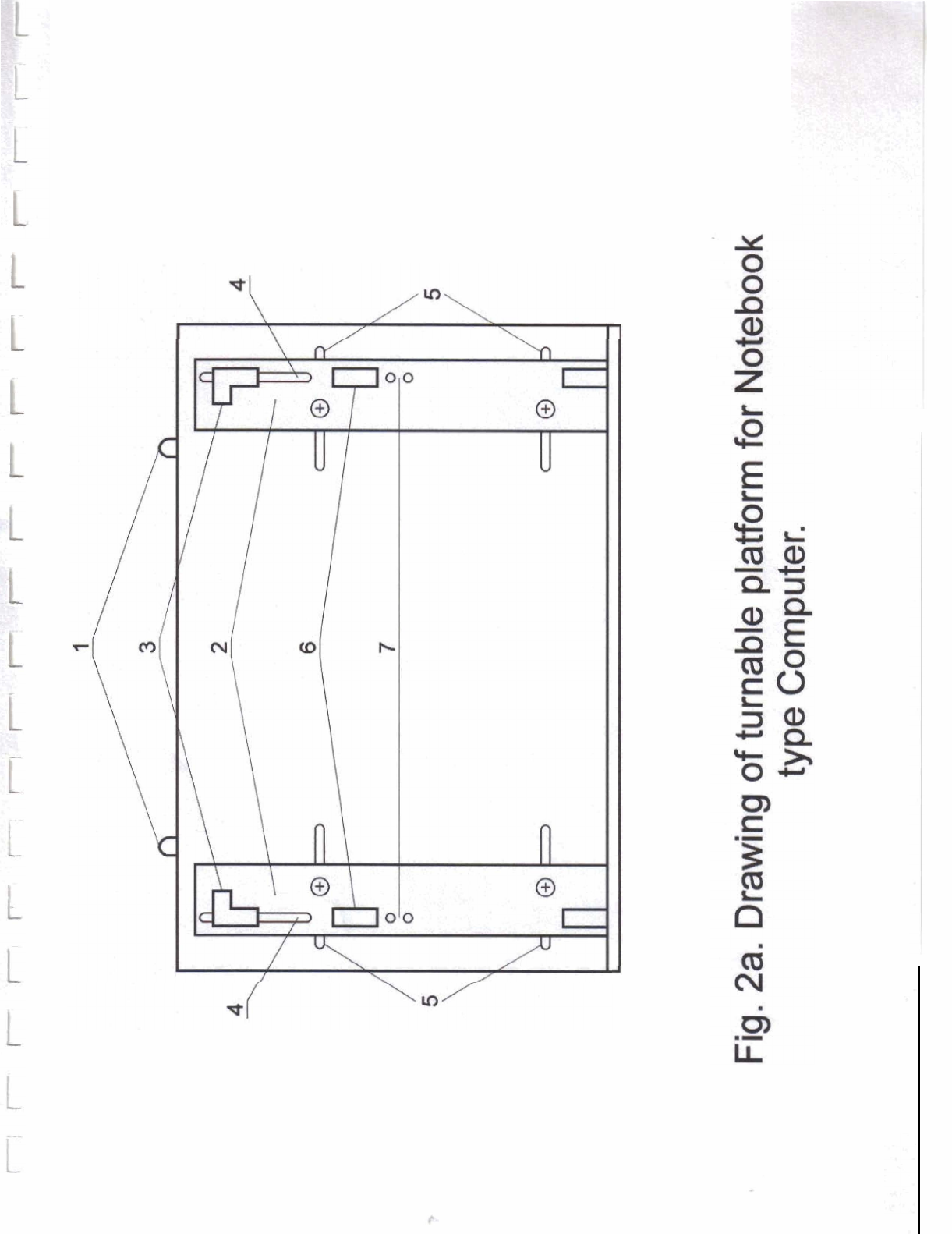
1) Place an IBM-compatible Notebook computer to the special platform located on top of the
control unit (Fig. 2a). The platform can be turned and fixed in two extreme positions.
Before installation of the computer remove fixing brackets made of stainless sheet steel.
Applying screwdriver unscrew for
1
turn screws fixing movable strips
2.
They are free now
and may be stand at distance equal to computer length
If it is necessary to adjust the platform to the computer width unscrew in full screws fixing
movable strips
2
and take away movable strips. Unscrew for 1-1,5 turns screws fixing the
movable bracket
3.
Now brackets
3
can be moved along slots
4
and adjustment of fixture
according to dimensions of the computer is possible. It is recommended to make this placing
the computer on the platform. Adjusting up positions of movable strips
2
and brackets
3
mark
they positions by pencil. Take away the computer and screw screws fixing movable brackets
3
and strips
2.
Do not apply efforts tightening screws since this can cause deformation of the
strip.
Place the computer and fix by means of fixing brackets made of stainless sheet steel.
Should fixing stand
6
with the fixing bracket hinder to operate the computer, it can be moved
into another position
7.
2) Connect the data communication cable to the control unit and to the LAN connector of the
computer as shown in Fig. 1.
3) Connect the power cable to the control unit and to the battery.
4) Assemble the antenna. If a high frequency antenna is applied (1 00, 300, 500, 900 MHz, 1.5
or 2 GHz), it is required to attach the handle and to connect the antenna cable to the antenna.
3-m antenna cable should be attached to the handle by plastic clamps or adhesive band as it is
shown in Fig.3. 20-m antenna cable is fixed on antenna by special clamp as it is shown in
Fig.3a. The 100 MHz antenna is combined as shown in Fig. 6. Each 100 MHz antenna has
two 5-pin connectors. Attaching cables to antenna operator may use any of two connectors
because they are connected in parallel. If odometer wheel is needed it is attached to antenna as
shown in Fig. 3b and 6a. Survey wheel is connected to antenna via 3
-
pin connector. The
operation combination of the low frequency antenna 38-150 MHz is shown in Fig. 5.
Transmitting and receiving antennas are fixed to the grip via articulators those may be fixed at
angles of 0, 30, 60 and 90 degrees to the vertical. The cables are attached to the grip by plastic
clamps or adhesive band. After joining of cables in the middle of the grip they should be
fasten together by adhesive band every 10
-
15 cm. The method of attachment of 0,5 m (150
MHz) and 1 m (75 MHz) dipoles is illustrated by Fig. 7. To operate at frequency 38 MHz
attach additional dipoles according to Fig.8. The operation combination of the 750 MHz
antenna is shown in Fig. 12. Special cable with color rings on connectors to be connected to
antennas is provided. Assambling antenna you have to coincide color marks on antenna
connectors and cable.
5) Connect the antenna to the control unit. Usually one antenna unit is used for profiling
because it contents both transmitting and receiving antennas. In case when separated antennas
for transmitting and receiving are needed (for example in measurements by Common Depth
Point method) the second antenna is connected to the Control Unit as it is shown in Fig1 .b. In
this case antenna 1 transmits but antenna 2 receives signals.
2.2.
Switching
ON
of
the
Georadar.
Warning: Before switching ON the georadar please make sure that antenna is in correct
position, i.e. surface coupled antenna 100 MHz, 300 MHz, 500 MHz, 900 MHz, 1.5 GHz,
2 GHz is placed on the surface of ground or wall, but 38
-
75
-
150 MHz or 750 lWHz
antenna
-
in proximity to the surface of ground or wall.
Zond
-
12e georadar has build
-
in deactivating mechanism, i.e. transmitter is switched ON
only when operator enters SETUP menu item or START data acquisition. Transmitter
switches OFF immediately after operator STOP data acquisition or leaves SETUP menu
item.
1) Switch ON the georadar by means of toggle switch
7
located in the middle of the control
unit and marked with symbol 110. LED
2
is to light on. If voltage of the battery is lower than
specified (about 10.5 V) LED
3
will begin blink and Control Unit will blow interrupted
sounds.
2) Switch on the computer and install package
Prism2
on the fixed disk from CD supplied.
The procedure of installation is described in Program Prism2 User's Manual. After
installation please perform compulsory actions prescribed by section 5.1
"
Configuring the
computer to connect with Zond
-
12e Georadar Control Unit
"
and section 6
"
What to Do
Immediately After Installation
"
of the Program Prism2 User's Manual.
3) Further operations on radar adjustment and survey are described in sections 8 and 9 of the
Program Prism2 User's Manual.
4) In case of pedestrian operation using belts supplied fix the control unit on the breast of the
operator as it is shown in Fig. 4. For the computer operation convenience turn and fix the
platform. The battery is carried in the special shoulder bag. Antennas 100, 300, 500, 900
MHz, 1.5 and 2 GHz are dragged on surface of ground, the antenna 38
-
1 50 MHz is carried by
hand in height of 0.15
-
0.4 m (depending of raggedness of ground surface). The antenna 750
MHz is carried above ground in height of 0.2-0.3m.
5) The georadar "Zond-12e" is supplied with the sealed lead battery of voltage 12 V and
capacity 7
Ah.
To achieve the maximum capacity charging is to be done by automatic charger
supplied together with the battery. To charge the battery by means of the automatic charger at
first connect the battery to the charger and then plug the charger to outlet 220 (1 10) VAC, 50
(60)
Hz.
During charging the LED will change it's color from red to yellow and finally green.
Disconnect the battery and disconnect the charging device from the main 220 (1 10) VAC, 50
(60) Hz.
3.
CLIMATE OPERATION ENVIRONMENT
3.1.
The georadar can be operated at air temperature from 236OK (
-
10°C) to 3 13°K (+40°C)
and relative humidity up to 95% at temperature 308°K (+35"C).
3.2.
It is allowed operation of the georadar also at lower temperature applying the heat
insulating cover for the control unit.
3.3
The antennas of georadar "Zond-12e" is designed
as
humidity and splash protected
device and short time immersion into water of it is allowed. When working in rain it is
recommended to apply waterproof cape to protect the control unit and the computer from
direct action of rain. After operation in humid weather it is necessary to wipe the antenna and
the control unit with dry soft clothes and dry it in warm premises.
3.4.
It is not recommended to switch on the georadar earlier than after an hour after its transfer
from environment having negative temperature to a warm premise.
3.5.
In case of operation of the georadar in conditions of high air temperature (higher than
+40°C) it is not recommended to leave the instrument in place where it can be affected by
direct sun stares.
4.
GENERAL FAILURES AND THE WAYS OF THEIR
REMOVAL
Description of a failure, its Possible cause of failure Method of removal
visible symptoms and
additional symptoms
1 2 3
1.
The LED does not light on The fuse has blown To replace the fuse
upon switching on of
UO
toggle switch The LED has failed To replace the LED
I10 toggle switch has failed To replace the toggle switch
Break in the power cord To remove break
2.
Test signal absent on the Break in the cable connecting To remove break
screen in
Test
mode. the control unit and the
computer
The computer has been To specify according to
incorrectly configured or User's Manual
Radar
1
Connection settings
are incorrect.
3.
Signal is absent in mode Incorrect setting of To set up according to the
Sounding, yet present in Pulse Delay Manual
Test mode Failure of the antenna To replace the antenna
-
5.TRANSPORTATION RULES
-
5.1. In case of observing of rules of packaging of the instrument according to the Operation
Manual it is allowed its transportation in soft and rigid package by railway, road and air
transport without restriction of distance.
-
6.
GUARANTEES
7.1.
Radar Systems Inc. guarantees free of charge repair of any components of the georadar
and eliminate any defects for one year commencing on the date of purchase under
condition of delivery of failed components to Radar Systems, Inc. address. Warranty does
not extend to the case of mechanical damages due to incorrect use. In all other cases repair
is performed for extra pay.
Our address: Radar Systems Inc., Lomonosova Street 1, B
-
406, Riga LV
-
10 19, Latvia.
PhoneIFax: (+37 1)
-
7 14 1041. E
-
mail: radsys@radsys.lv
7. CE Declaration of Conformity
For the following equipment:
Georadar Zond
-
12e consisting of:
1. Control Unit;
2. Antenna 300 MHz;
3. Antenna 500 MHz;
4. Antenna 900 MHz;
5. Antenna 1.5 GHz;
6. Antenna 2 GHz
is herewith confirmed to comply with the requirements set out in the Council Directive on the
Approximation of the Laws of the Member States relating to Electromagnetic Compatibility
and Radio Spectrum Matters (99/5/EC), Low
-
voltage Directive (73123lEEC) and the
Amendment Directive (93168lEEC). For the evaluation regarding the Directives, the
following standards were applied:
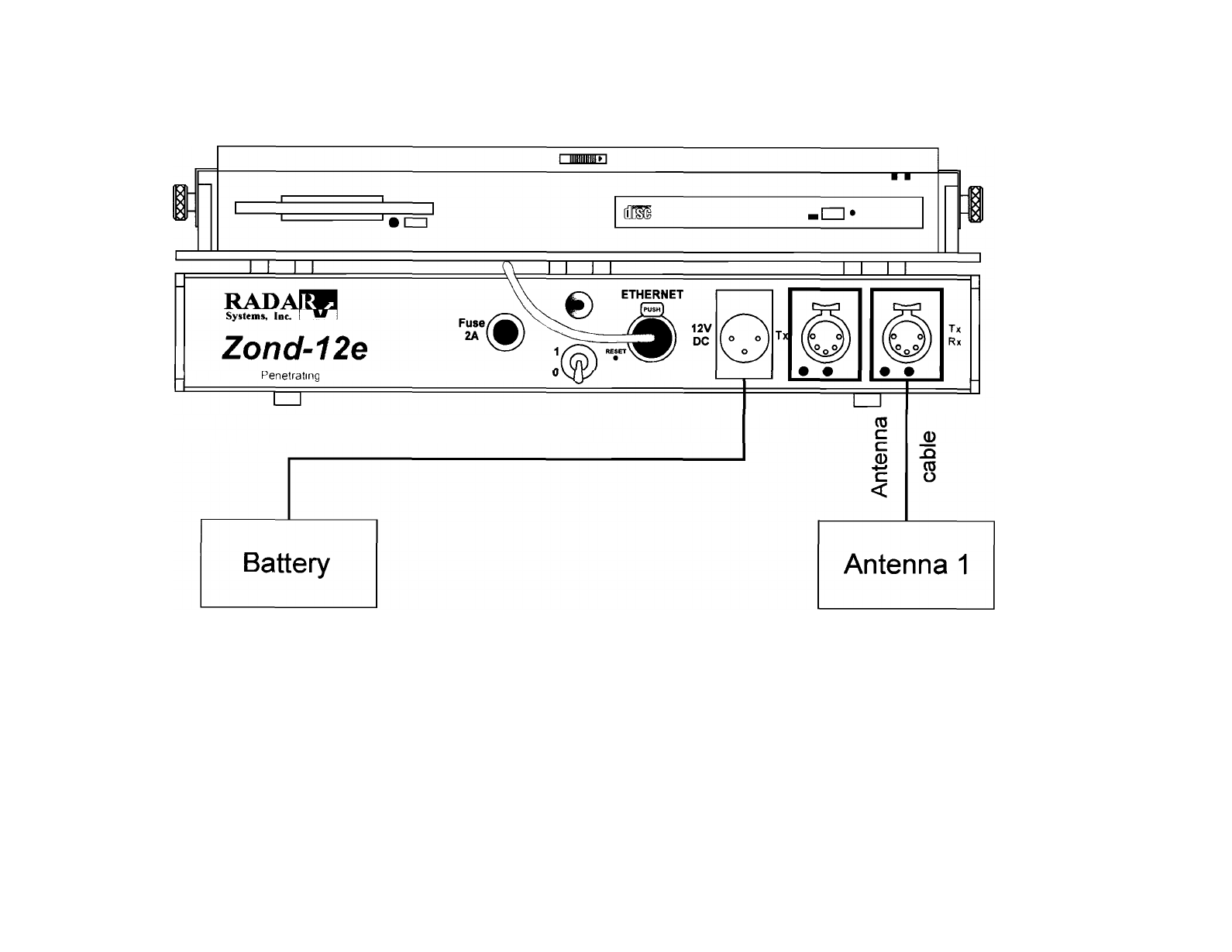
Ground Penetrat~ng Radar
Power
cable
Fig. 1. Schematic drawing of Zond
-
12e system components
connections using high frequency antenna.
Power
cable
1
Battery
Fig.
I
a.
Schematic
drawing
of
Zond
-
12e
system components
"ti
E
wL
Ee
*
Y)
a
m
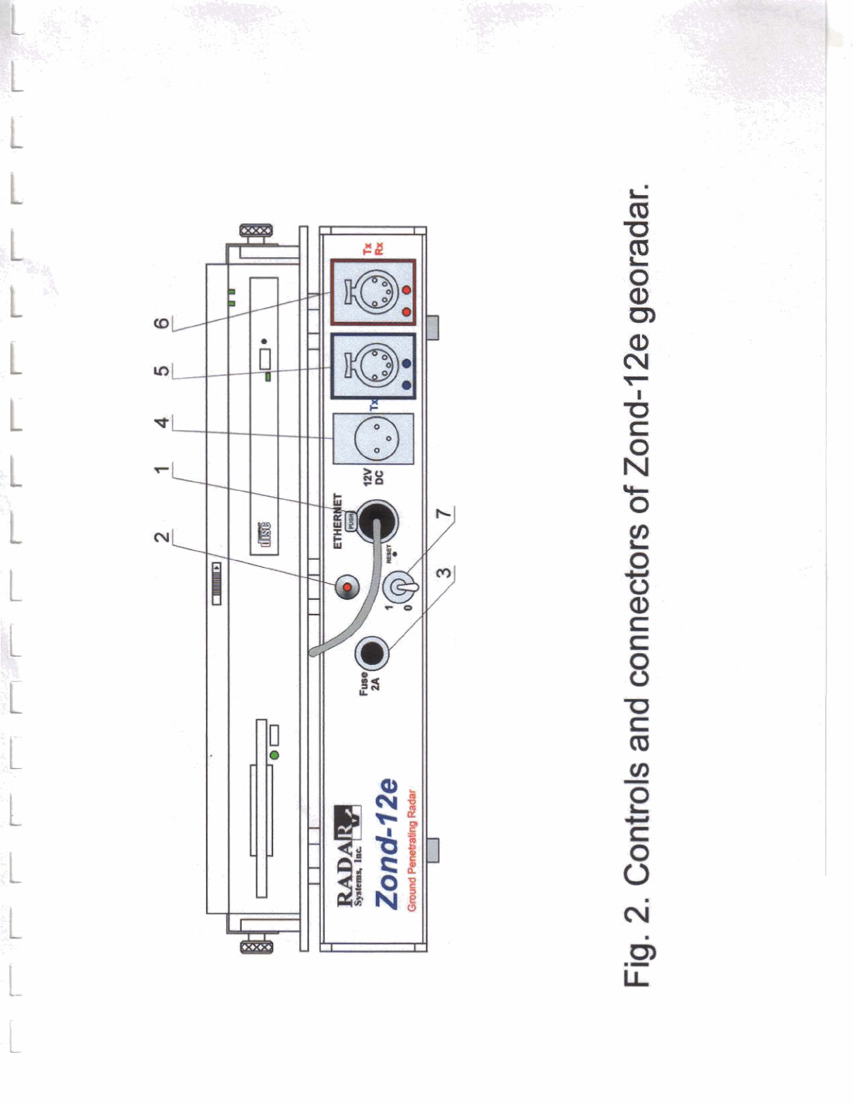
DESCRIPTION OF CONTROLS AND CONNECTORS
OF THE GEORADAR ccZond-12e"
1. The connector for the cable connecting with the computer.
2. Indicating power
LED.
3.
Fuse 2
A.
4.
Connector for connecting of the power cord
.
5.
Connector for connecting of transmitting antenna only.
6.
Connector for antenna connecting.
7.
The toggle switch for switching on of the georadar.
PIN SPECIFICATION OF ANTENNA CABLE CONNECTOR
1
-
Ground.
2
-
Transmitter triggering pulses combined with DC +12V.
3
-
Receiver triggering pulses combined with DC +12V.
4
-
Receiver output signal.
5
-
Pulses from odometer wheel.
PIN SPECIFICATION OF ODOMETER WHEEL CABLE CONNECTOR
1
-
Pulses from odometer wheel.
2
-
DC +12V.
3
-
Ground
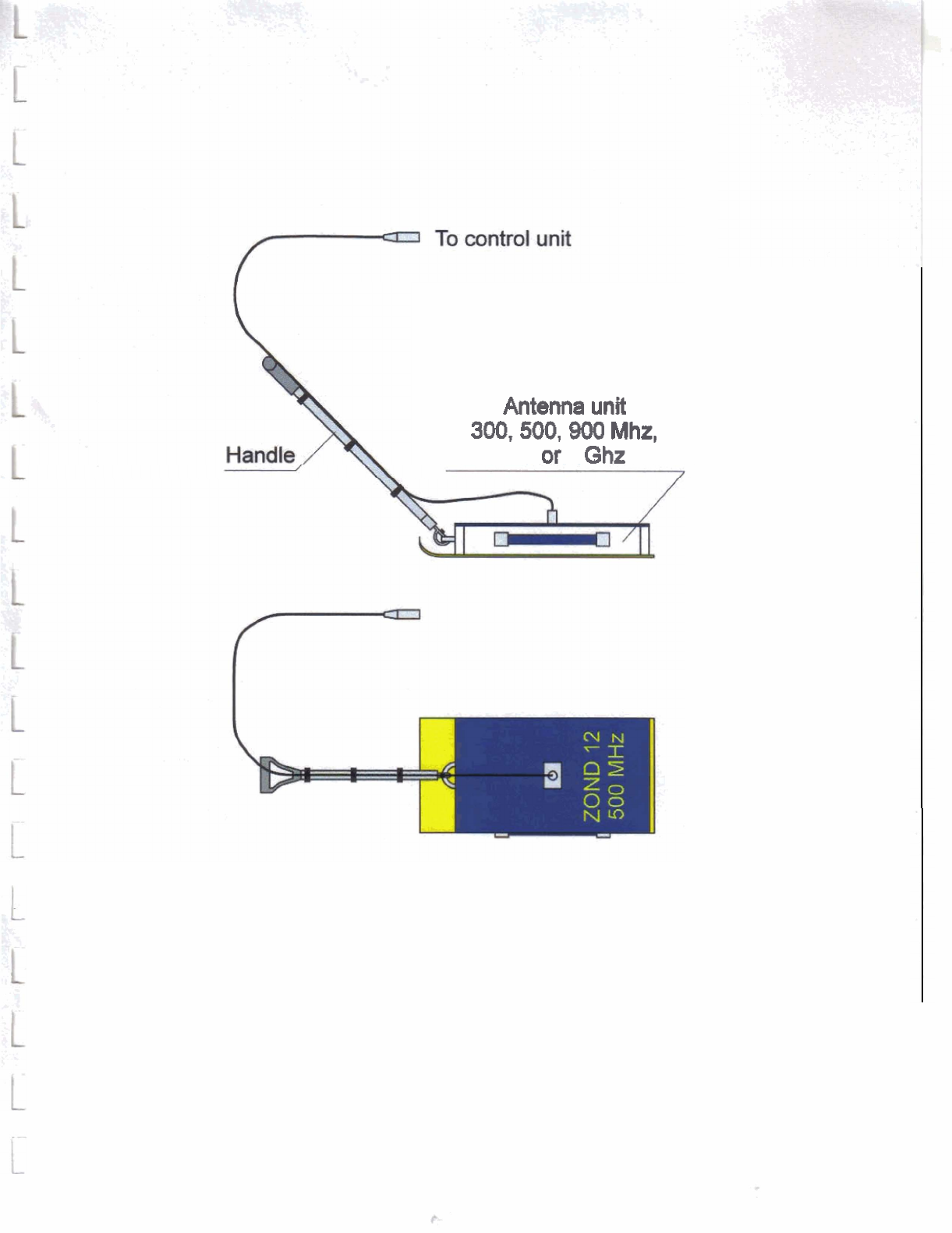
Antenna
unit
300,500,900
Mhz,
1.5
or
2
Ghz
Fig.
3.
Attaching
of
handle
and
3
m
cable
to
antenna
unit.
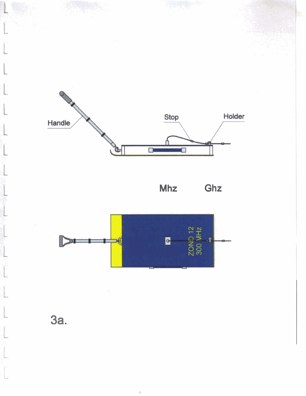
Antenna
unit
300,500,900
Mhz
or
1.5
Ghz
Fig.
3a.
Attaching
of
handle
and
20
m
cable
to
antenna
unit.