Actiontec Electronics T3200BV Bonded VDSL2/G.fast Wireless AC Gateway Router User Manual 1 intro indd
Actiontec Electronics Inc Bonded VDSL2/G.fast Wireless AC Gateway Router 1 intro indd
Contents
- 1. User Manual (1 of 2)
- 2. User Manual (2 of 2)
User Manual (1 of 2)

User Guide
Bonded VDSL2/G.fast
Wireless AC
Gateway Router
Model # T3200BV
0xxx-00xx-000 rev. x

i
Table of Contents
1 Introduction 4
Package Contents 4
Minimum System Requirements 4
Features 5
Getting to Know the Gateway 5
Connecting the Gateway 7
2 Accessing the Home Screen 9
Accessing the Home Screen 9
Icon Bar 11
Connection Status 11
3 Checking the Gateway’s Status 12
Accessing the Status Screens 12
Connection Status 13
Line 1/Line 2 Status 14
WAN Ethernet 15
Routing Table 15
Firewall Status 16
NAT Table 16
Wireless Status 17
Modem Utilization 19
LAN Status 20
ARP Table 20
Network Devices 21
Interface Statistics 21
Multicast Statistics 22
System Log 22
4 Configuring Wireless Settings 23
Accessing Wireless Settings 23
Basic Settings 24
Advanced Settings 25
WPS 26
MAC Address Control 27
Band Steering 28
i

ii
Table of Contents
ii
5 Configuring Firewall Settings 29
Accessing Firewall Settings 29
Firewall 30
IPv6 Firewall 31
Port Forwarding 32
Applications 33
DMZ Hosting 34
IPv6 DMZ Hosting 35
UPnP 36
6 Advanced Settings 37
Accessing the Advanced Setup Screens 37
Services Blocking 38
Website Blocking 39
Scheduling Access 40
Parental Controls 41
WAN IP Addressing 42
IPv6 WAN Settings 43
LAN IP Settings 44
IPv6 LAN Settings 45
DHCP Reservation 46
Dynamic DNS 47
DNS Host Mapping 48
Port Bridging 48
MoCA LAN Setup 49
Remote GUI 51
Remote Telnet 51
Dynamic Routing 52
Static Routing 53
Admin Password 54
NAT 54
Storage Device Info 55
Samba Configuration 55
Reboot 56
Restore Defaults 56
Speed Test 57
Ping Test 58
Iperf Test 59

iii
Table of Contents
IPv6 Ping Test 60
Traceroute 61
IPv6 Traceroute 61
Time Zone 62
Config Download/Upload 62
Upgrade History 63
ALG 63
DLNA 64
Load Customer Default Config 64
Print Server 65
xDSL Diagnostics 65
A Specifications 66
General 66
Wireless Operating Range 67
LED Indicators 67
Power Adapter 67
Environmental 68
Notices 69
Warranty 69
Important Safety Instructions 69
FCC Class B Equipment 70
Important Note on Wi-Fi 71
Contact Info 72

4
Introduction
Congratulations on purchasing the T3200BV Bonded VDSL2 /G.fast Wireless
AC Gateway Router. The Gateway is a single platform device that supports
universal WAN access, FTTN, FTTdp, FTTB, or FTTP. With support for
advanced 802.11ac 4x4 WiFi, the Gateway enables blazing fast HD video
streaming, with multi-channel HD video throughput. The Gateway also offers an
unprecedented level of security, helping protect your network resources. It has
also been designed to deliver unparalleled WiFi performance, using dual-band
WiFi supporting speeds up to 2.3 Gbps.
Package Contents
• Black Power adapter
• Yellow cable (Ethernet, 6 ft.)
• White cable (Ethernet, 10 ft.)
• Quick Start Guide
• Installation Guide
• Wall-mount template
• Vertical stand
Minimum System Requirements
• Active ADSL2+ service
• Computer with an 10 Mbps or 10/100/1000 Mbps Ethernet connection
• Microsoft Windows 10, 8, 7; Mac OS OS X+
• TCP/IP network protocol installed on each computer
1

5
T3200BV Gateway
Features
• ADSL2+, VDSL2, G.fast, WAN Ethernet and Fiber in a single CPE
• Dual Band WiFi delivering up to 2.3 Gbps with 802.11ac 4x4 5GHz and
802.11n 3x3 2.4GHz
• Optimized for IPTV and Video over WiFi
• SFP cage for G.fast or EPON/GPON ONT modules
Getting to Know the Gateway
This section contains a quick description of the Gateway’s lights, ports, and other
features. The Gateway has several indicator lights (LEDs) and a button on its front
panel, and a series of ports and switches on its rear panel.
Front Panel
The front panel of the Gateway features 2 LEDs (Internet and Wi-Fi), and a WPS
(Wireless Protected Setup) button.
Internet
The Internet LED illuminates green when the Gateway is properly connected to
a WAN Internet connection.
Wi-Fi LED
The Wi-Fi LED illuminates green when the Gateway’s wireless network is oper-
ating and properly configured.
WPS Button
The WPS button is used when connecting a wireless device to the Gateway’s
wireless network using WPS.

6
Introduction
Rear Panel
The rear panel of the Gateway features 10 ports, and a Reset button.
Power Port
The Power port is used to connect the Power cord (Model No. CDS036-
W120U, made by Adapter Technology Co Ltd) to the Gateway.
Reset Button
Depressing the Reset button for 10 seconds will restore the Gateway’s factory
default settings. The reset process will start after releasing the button.
WARNING! Do not unplug the Power cord from the Gateway
during the reset process. Doing so may result in permanent damage
to the Gateway.
SFP Cage
The SFP cage is used to connect the Gateway to a service provider connection
via optical fiber cable.
WAN Ethernet Port
The WAN Ethernet port is used to connect the Gateway to a WAN connection
via an Ethernet cable.
LAN Ethernet Ports (4)
The LAN Ethernet ports are used to connect computers to the Gateway via
Ethernet cable. The Ethernet ports are 10/100/1000 Mbps auto-sensing ports,
and either a straight-through or crossover Ethernet cable can be used when con-
necting to the ports.
USB Port
The USB port is used to connect the Gateway to a USB device.
7
T3200BV Gateway
DSL Ports (2)
The DSL ports are used to connect the Gateway to a DSL wall outlet via DSL
cable. For single line DSL, use the DSL 1 port.
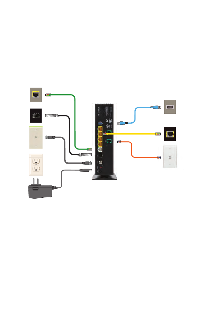
Connecting the Gateway
There are many variables involved when connecting the Gateway, depending on
the type of Internet service available. The figure below shows all of the possible
connections available for the Gateway.
Power
Outlet
Power
Adapter
Coaxial
Outlet
MoCA
Cable
T3200M
Optical
Fiber
Cable
WAN Ethernet
Cable
LAN Ethernet
Cable
Ethernet
Port of
Device
WAN
Ethernet
Port
USB
Cable
USB
Port of
Device
Service
Provider
C
onnection
(Rear Panel)
DSL
Cable
DSL
Outlet
Connecting a Computer to the Gateway
To connect a computer to the Gateway to access the Gateway’s graphical user
interface (GUI):

8
Introduction
1. Get the Gateway and black Power cord from the box.
2. Plug the black Power cord in the black port on the back of the Gateway and
then into a power outlet.
3. Plug the yellow Ethernet cable from the box into one of the four yellow
Ethernet ports on the back of the Gateway.
4. Make sure the computer is powered on, then plug the other end of the
yellow Ethernet cable into an Ethernet port on the computer.
5. Make sure that the LED on the LAN port into which the Ethernet cable is
plugged glows steadily green. This may take a few moments.
6. The computer should either be configured with a statically defined IP address
and DNS address, or instructed to automatically obtain an IP address using
the Network DHCP server. The Gateway is set up, by default, with an active
DHCP server, and it is recommended to leave this setting as is.
9
Accessing the
Home Screen
This chapter gives a short overview of the Home screen of the Gateway’s graphical
user interface (GUI).
Accessing the Home Screen
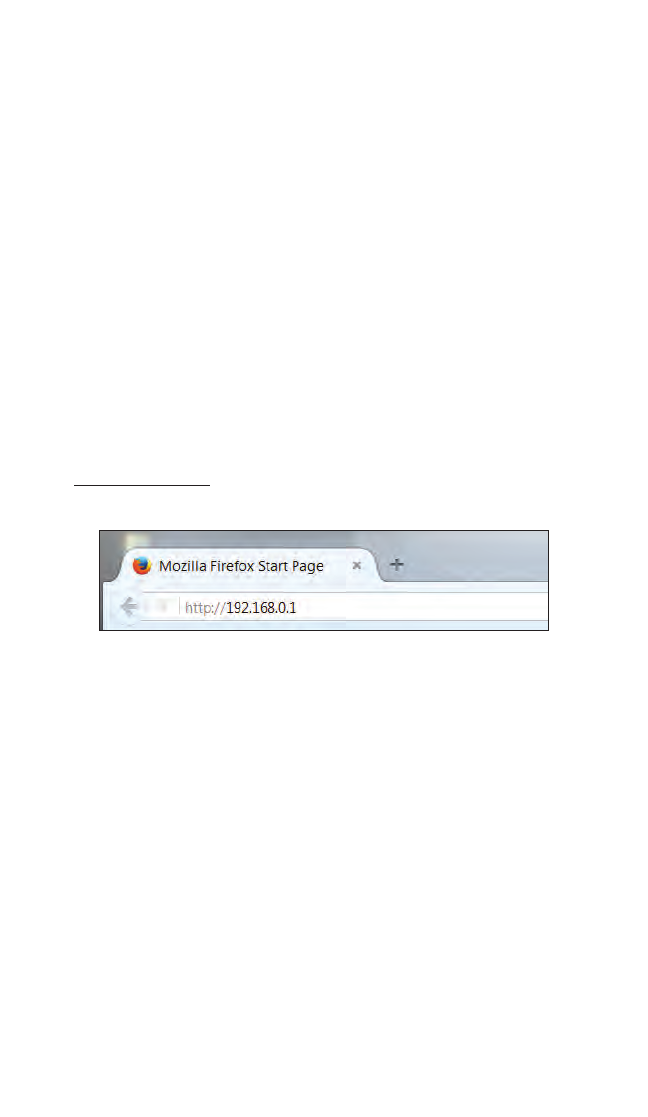
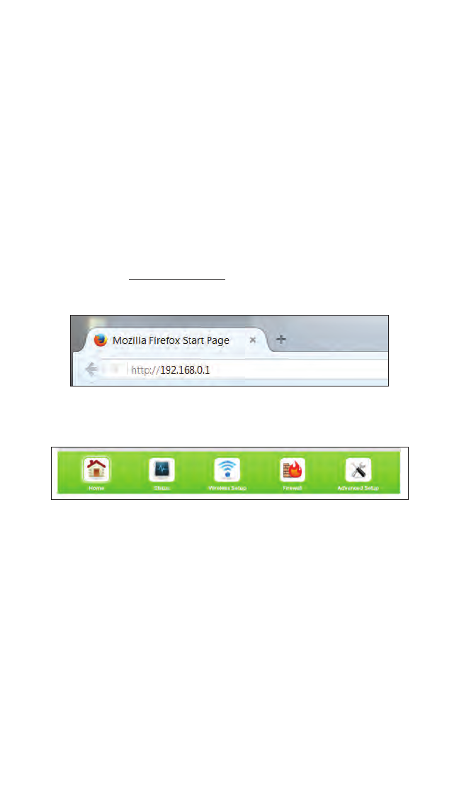
To access the Home screen:
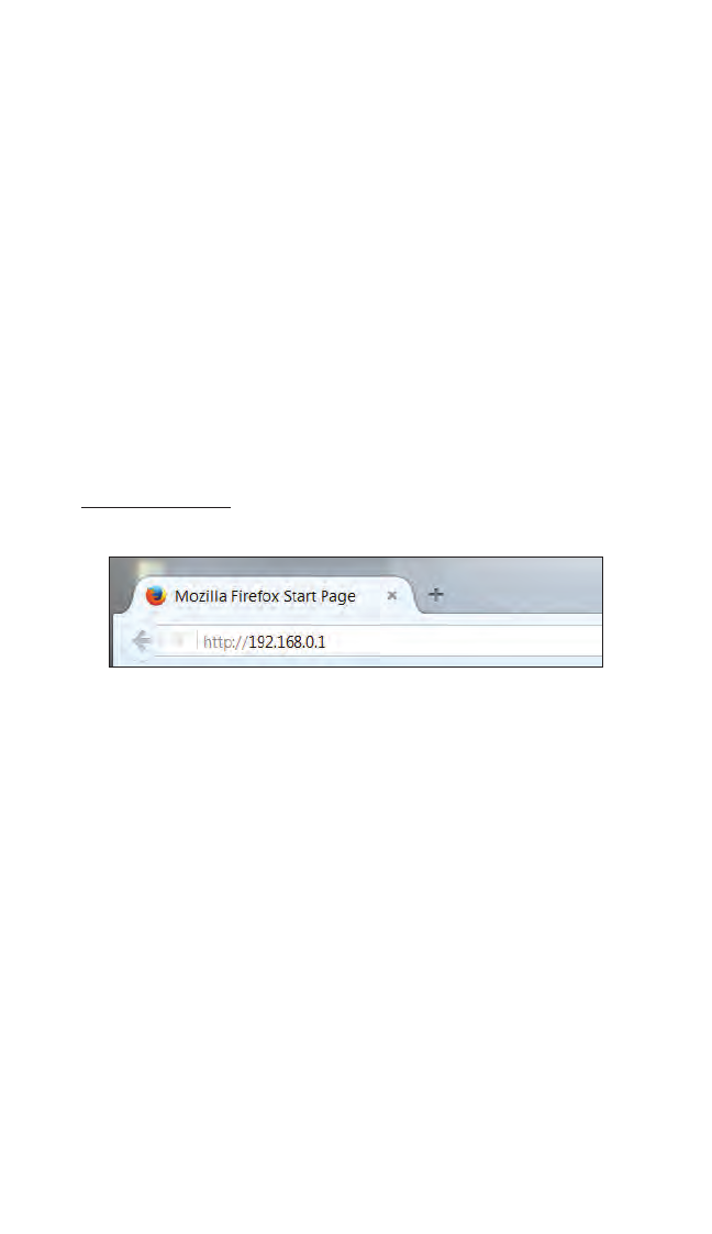
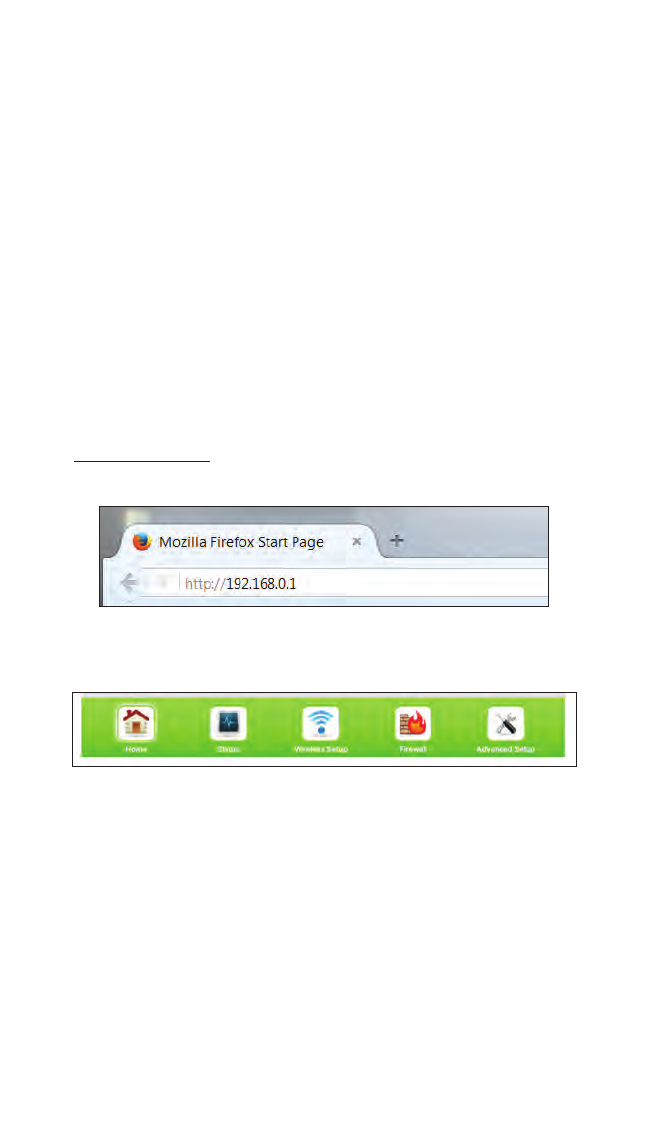
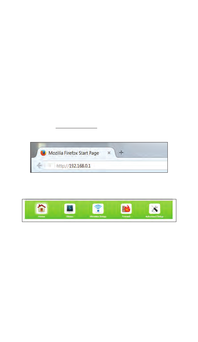
1. Open a Web browser on computer connected, via Ethernet cable, to one of the
Gateway’s LAN ports. In the Address text box, type:
http://192.168.0.1
then press Enter on the keyboard.
2
10
T3200BV Gateway
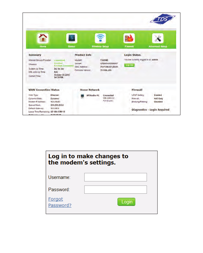
2. The Gateway’s Home screen appears.
3. Enter the username admin and the password found on the sticker on the side of the
Gateway in the Username and Password text boxes at the top right side of the screen,
then click Login.
Note: An option to change the password will appear the first
time a user logs in to the Gateway’s GUI.
The Gateway’s GUI is now accessible.
11
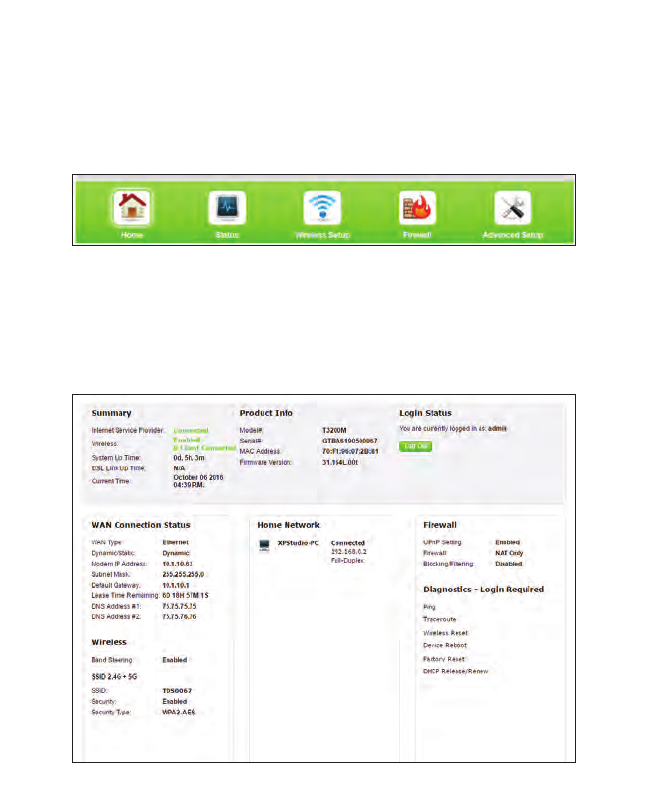
Home Screen
Icon Bar
At the top of the Home screen is the Icon Bar. Here, you can quickly access the
other four main sections of the Gateway’s GUI by clicking on the appropriate icon:
Status (see chapter 3 for more details); Wireless Setup (see chapter 4 for more
details); Firewall (see chapter 5 for more details); Advanced Setup (see chapter 6
for more details). Clicking Home in any other screen generates the Home screen.
Connection Status
The bottom of the Home screen consists of connection and device information
relating to the Gateway. There are no configurable options here.
12
Checking the
Gateway’s Status
This chapter explains the options available on the Status screens, which
display information about the Gateway’s network connections.
Accessing the Status Screens
To access the Gateway’s Status screens:
1. Open a Web browser. In the Address text box, type:
http://192.168.0.1
then press Enter on the keyboard.
2. The Gateway’s Main screen appears. Click the Status icon.
3
13
T3200BV Gateway
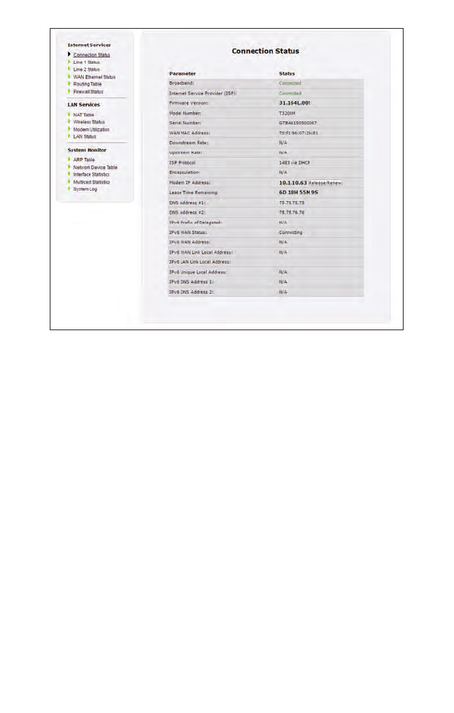
3. The Connection Status screen appears.
From here, all the Status screens can be accessed from the menu on the left.
Connection Status
Clicking Connection Status from any Status screen generates the Connection
Status (see figure, above). Information concerning the devices connected to the
Gateway’s network, whether wired or wireless, is displayed here, along with the
connected device’s IP address, MAC address, and (if applicable) IPv6 address.
14
Status
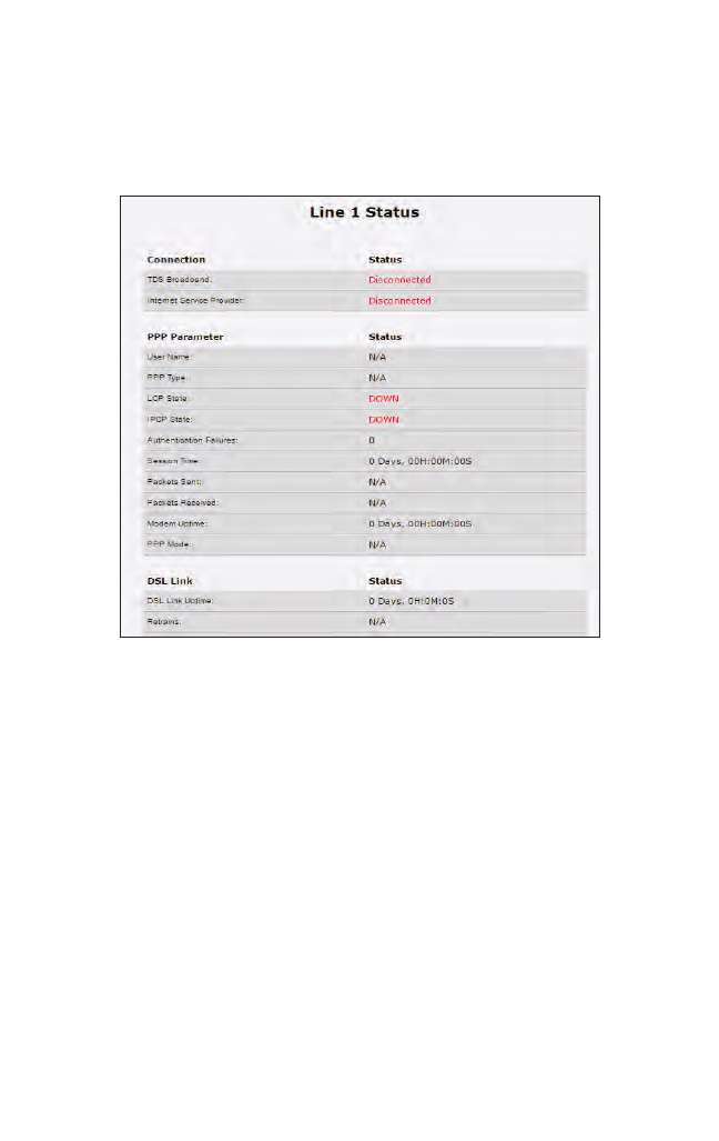
Line 1/Line 2 Status
Click Line 1 Status from any Status screen to generate the Line 1 Status screen.
This screen displays the Gateway’s DSL connection parameters for DSL Line 1 port.
Clicking Line 2 Status genreates the Line 2 Status screen, which displays the con-
nection parameters for the Gateway’s DSL Line 2 port.
15
T3200BV Gateway
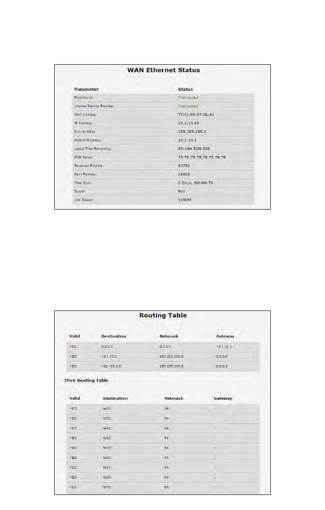
WAN Ethernet
Click WAN Ethernet from any Status screen to generate the WAN Ethernet Status
screen. This screen displays the Gateway’s WAN (wide area network) parameters.
Routing Table
Click Routing Table from any Status screen to generate the Routing Table screen.
This screen displays the Gateway’s routes.
16
Status
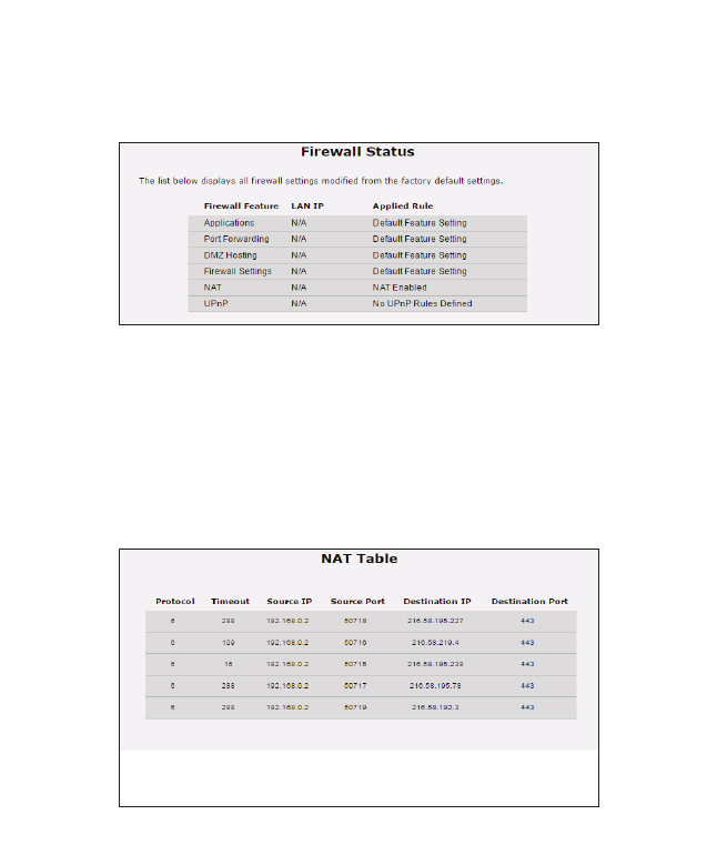
Firewall Status
Click Firewall Status from any Status screen to generate the Firewall Status screen.
This screen displays parameters concerning the Gateway’s firewall.
NAT Table
Click NAT Table from any Status screen to generate the NAT Table screen. This
screen displays the Gateway’s WAN (wide area network) parameters.
17
T3200BV Gateway
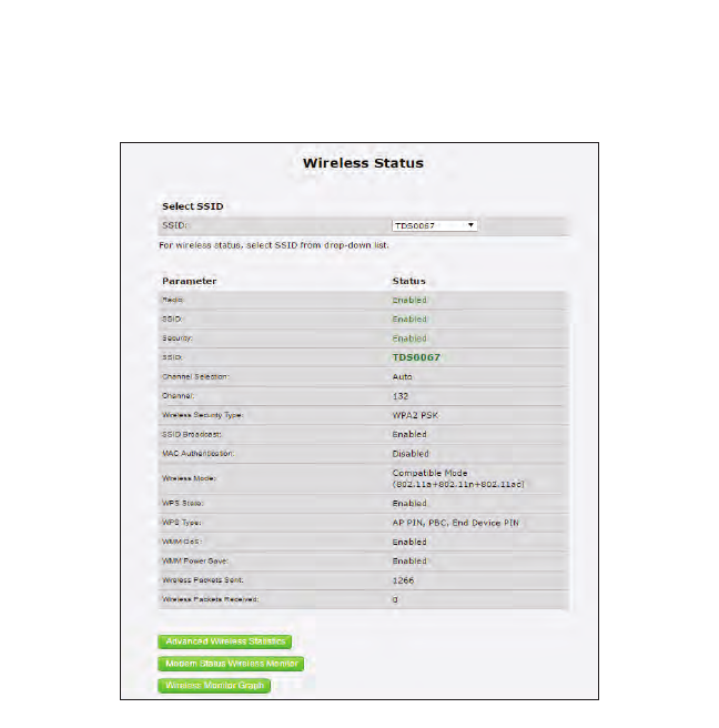
Wireless Status
Click Wireless Status from any Status screen to generate the Wireless Status
screen. This screen displays the Gateway’s wireless network parameters.
18
Status
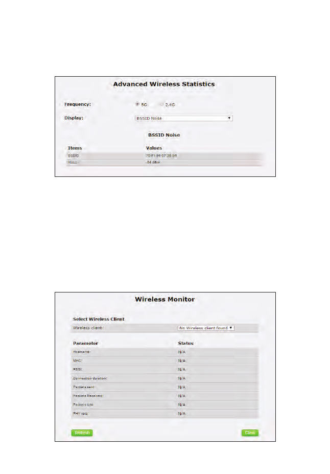
Advanced Wireless Status
Click Advanced Wireless Statistics from the bottom of the Wireless Status
screen to generate the Advanced Wireless Statistics screen. This screen displays the
Gateway’s additional wireless network parameters.
Wireless Monitor
Click Modemstatus Wireless Monitor from the bottom of the Wireless Status
screen to generate the Wireless Monitor screen. This screen displays parameters for
the clients connected to the Gateway’s wireless network.
19
T3200BV Gateway
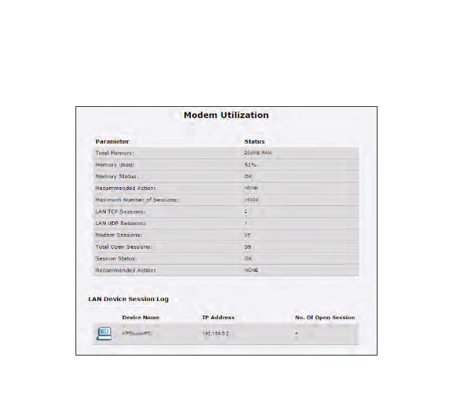
Modem Utilization
Click Modem Utilization from any Status screen to generate the Modem
Utilization screen. This screen displays statistics related to the Gateway’s modem
operation.
20
Status
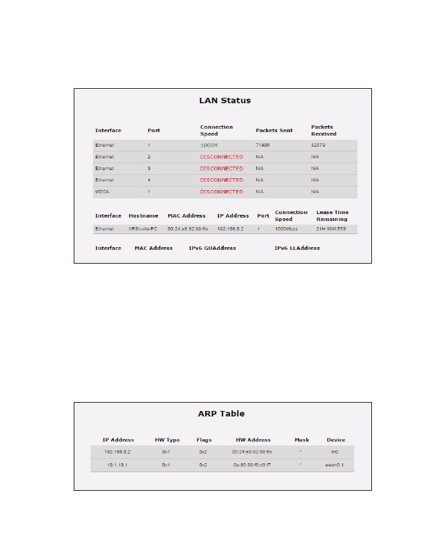
LAN Status
Click LAN Status from any Status screen to generate the LAN Status screen. This
screen displays the Gateway’s LAN (local area network) parameters.
ARP Table
Click ARP Table from any Status screen to generate the ARP Table screen. This
screen displays the Gateway’s ARP (address resolution protocol) table.
21
T3200BV Gateway
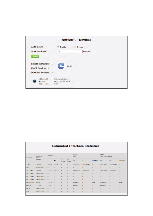
Network Devices
Click Network Devices from any Status screen to generate the Network - Devices
screen. This screen allows the user to scan the Gateway’s networks for new devices
at a selected time interval.
Interface Statistics
Click Interface Statistics from any Status screen to generate the Estimated
Interface Statistics screen. This screen displays various statistics and parameters
relating to the Gateway’s connection interfaces.
22
Status
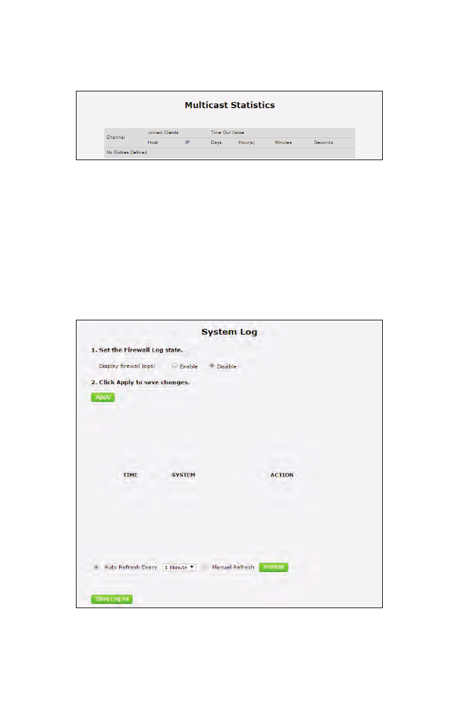
Multicast Statistics
Click Multicast Statistics from any Status screen to generate the Multicast
Statistics screen. This screen displays the Gateway’s multicast statistics.
System Log
Click System Log from any Status screen to generate the System Log screen. This
screen displays the Gateway’s system log, which keeps track of all events that occur
on the Gateway.
23
Configuring
Wireless Settings
This chapter explains the options provided in the Wireless Settings section of the
Gateway’s firmware, including basic and advanced settings, and WPS.
Accessing Wireless Settings
To access the Wireless Settings screens:
1. Open a Web browser. In the Address text box, type:
http://192.168.0.1
then press Enter on the keyboard.
4
24
T3200BV Gateway
2. The Gateway’s Main screen appears. Enter the user name and password,
then click Wireless Settings from the row of icons at the top of
the screen.
3. The Basic Settings screen appears, with a menu of other wireless options listed
on the left side of the screen.
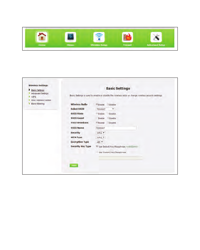
Basic Settings
Click Basic Settings from any Wireless Settings screen to generate the Basic
Settings screen, as shown in the figure above. This screen displays a series of
settings relating to the basic functionality of the Gateway’s wireless network,
including SSID (network name), frequency, and security.
25
Wireless
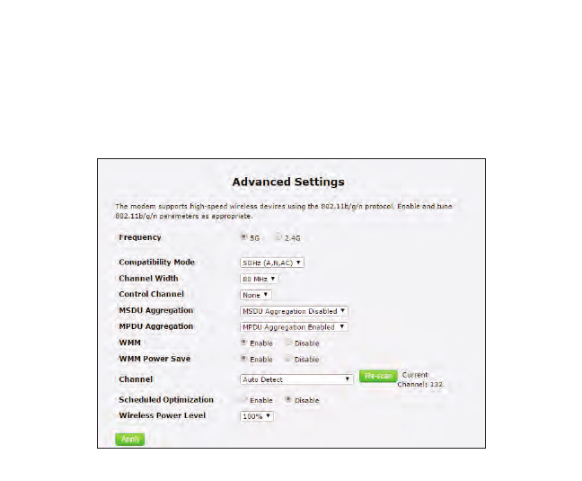
Advanced Settings
Click Advanced Settings from any Wireless Settings screen to generate the
Advanced Settings screen. This screen displays a series of settings relating to the
advanced capabilities of the Gateway’s wireless network, including compatibility
mode, channel width, and WMM power save.
26
T3200BV Gateway
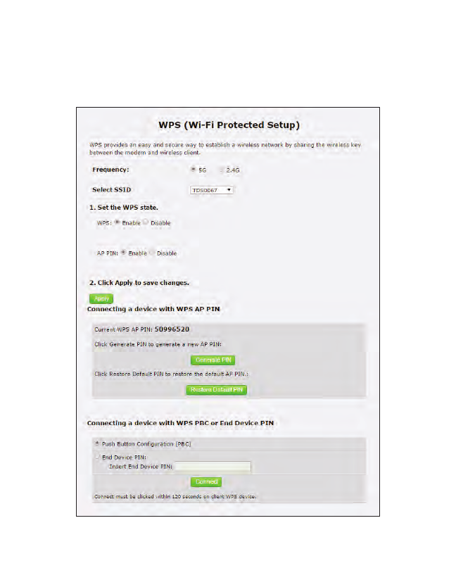
WPS
Click WPS from any Wireless Settings screen to generate the WPS (Wi-Fi Protected
Setup) screen, which allows the user to configure WPS by following the onscreen
instructions.
27
Wireless
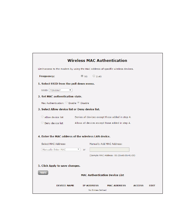
MAC Address Control
Click MAC Address Control from any Wireless Settings screen to generate the
Wireless MAC Authentication screen, which allows the user to configure allow or
deny access to the Gateway’s wireless network using the MAC address of the
wireless device. Follow the onscreen instructions to configure.
28
T3200BV Gateway
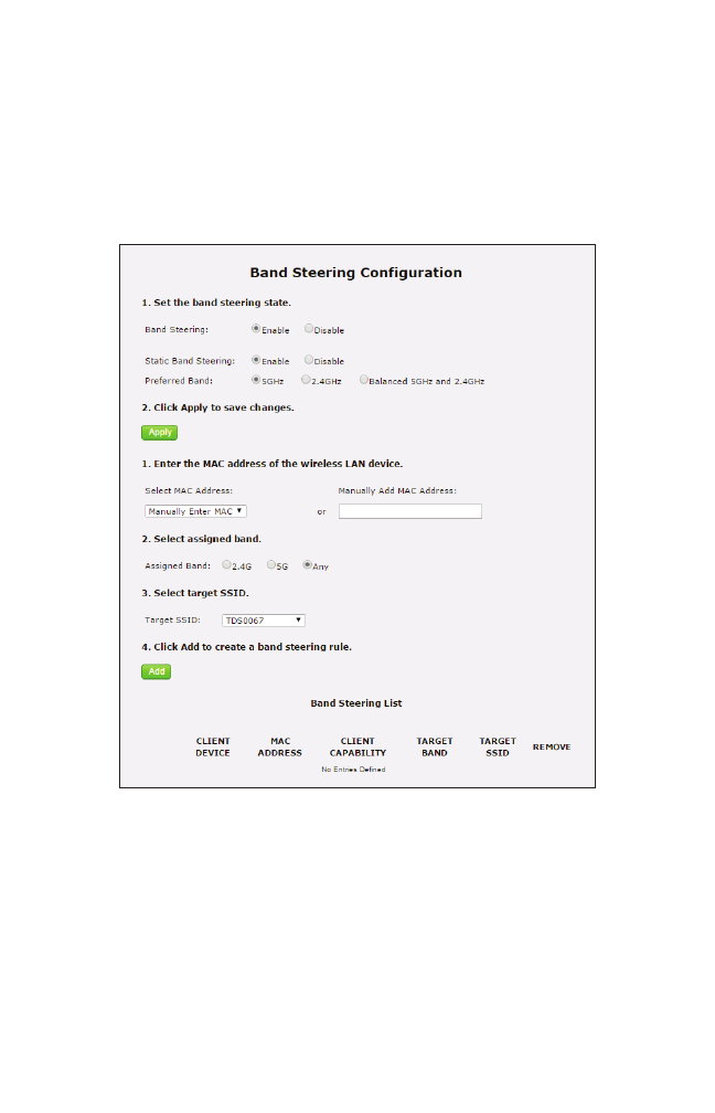
Band Steering
Click Band Steering from any Wireless Settings screen to generate the Band
Steering Configuration screen, which allows the user to configure the Gateway to
automatically connect 2.4GHz and 5GHz wireless devices to the appropriate wire-
less network bandwidth. Also, this screen can be used to assign a certain wireless
network and/or bandwidth to a particular wireless device. Follow the onscreen
instructions to configure.
29
Configuring
Firewall Settings
This chapter explains the options provided in the Firewall section of the Gateway’s
firmware, including setting up port forwarding and DMZ hosting.
Accessing Firewall Settings
To access the Firewall screens:
1. Open a Web browser. In the Address text box, type:
http://192.168.0.1
then press Enter on the keyboard.
The Gateway’s Home screen appears. Click the Firewall icon.
5
30
T3200BV Gateway
2. The Firewall screen appears, with a menu of other wireless options listed on the
left side of the screen.
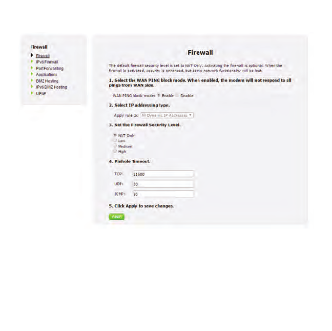
Firewall
Click General from any Firewall Settings screen to generate the Firewall screen, as
shown in the figure above. To configure basic settings of the Gateway’s firewall,
follow the onscreen instructions.
31
Firewall
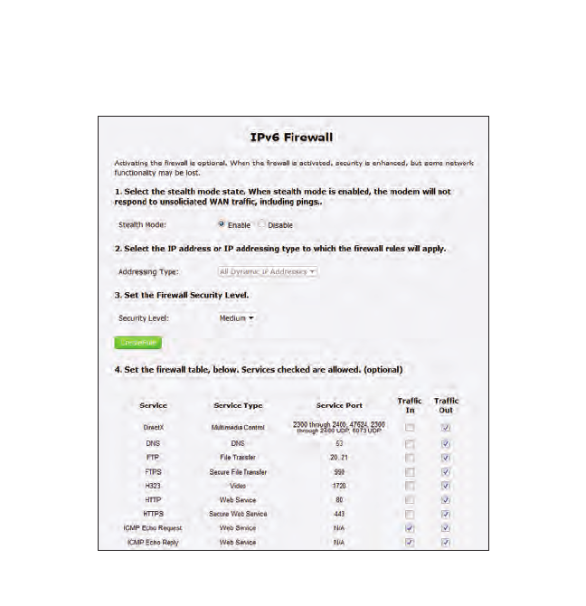
IPv6 Firewall
Click IPv6 Firewall from any Firewall Settings screen to generate the IPv6 Firewall
screen. To set up, follow the onscreen instructions.
32
T3200BV Gateway
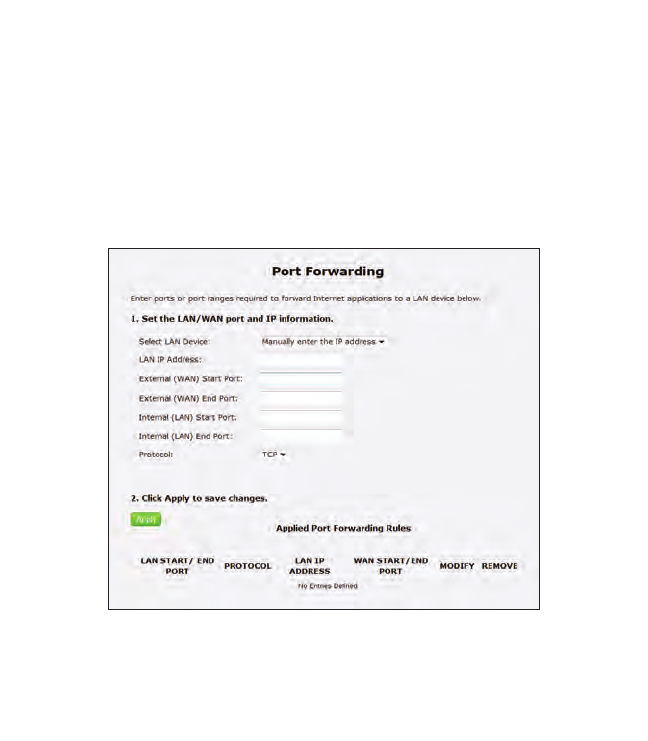
Port Forwarding
Click Port Forwarding from any Firewall screen to generate the Port Forwarding
screen. Activating port forwarding allows the network to be exposed to the
Internet in certain limited and controlled ways, enabling some applications to work
from the local network (game, voice, and chat applications, for example), as well as
allowing Internet access to servers in the local network. This screen allows you to
configure the port forwarding settings of the Gateway. If changes are made in this
screen, click Apply at the bottom of the screen to save them.
Port forwarding settings should only be adjusted by experienced technical users
who are extremely familiar with networking concepts.
33
Firewall
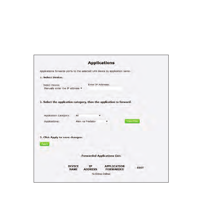
Applications
Click Applications from any Firewall screen to generate the Applications screen.
This screen allows the user to designate certain applications to be forwarded, cir-
cumventing the usual firewall security settings. If changes are made in this screen,
click Apply at the bottom of the screen to save them.
34
T3200BV Gateway
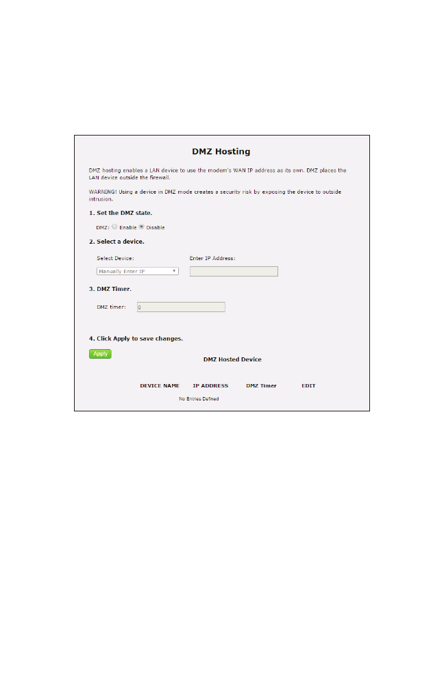
DMZ Hosting
Click DMZ Hosting from any Firewall screen to generate the DMZ Hosting screen.
The DMZ host feature allows one device on the network to operate outside the firewall
to use an Internet service that otherwise would be blocked, or to expose a networked
device to all services without restriction or security. To activate, click in the Enable
radio button, then enter the device’s IP address in the appropriate text boxes.
Caution! A DMZ host is not protected by the firewall and may be
vulnerable to attack. Designating a DMZ host may also put other
computers in the local network at risk. When designating a DMZ
host, consider the security implications and protect it if necessary.
35
Firewall
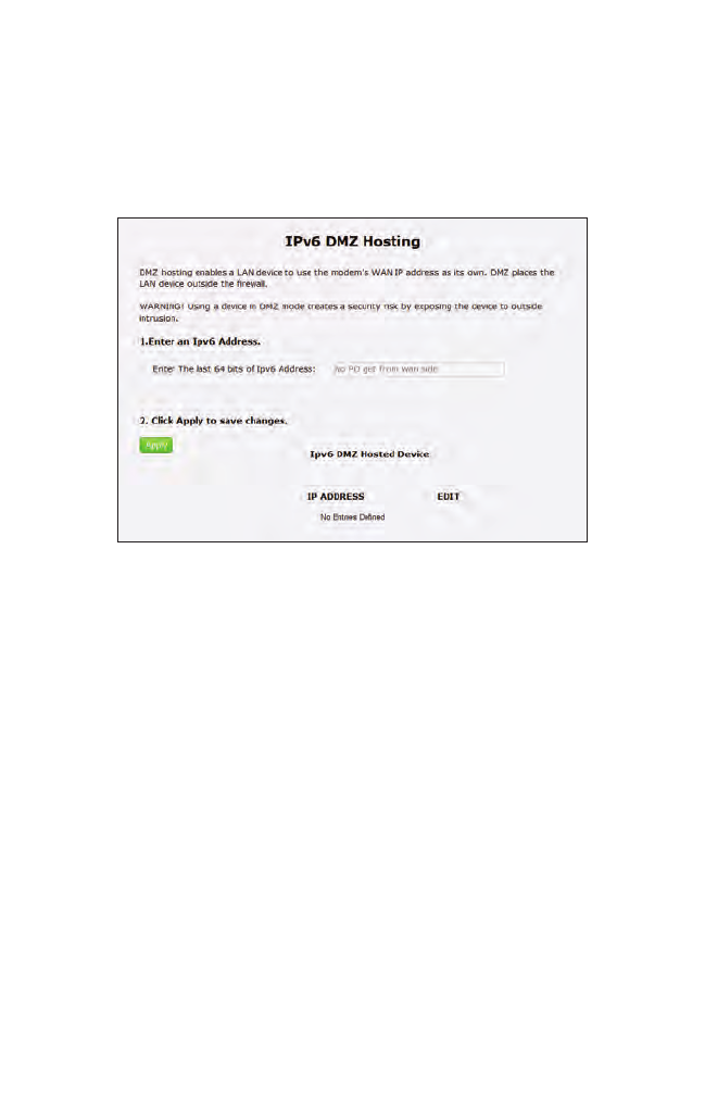
IPv6 DMZ Hosting
Click IPv6 DMZ Hosting from any Firewall screen to generate the IPv6 DMZ
Hosting screen. The DMZ host feature allows one device on the network to operate
outside the firewall to use an Internet service that otherwise would be blocked, or to
expose a networked device to all services without restriction or security. To activate,
follow the onscreen instructions.
Caution! A DMZ host is not protected by the firewall and may be
vulnerable to attack. Designating a DMZ host may also put other
computers in the local network at risk. When designating a DMZ
host, consider the security implications and protect it if necessary.
36
T3200BV Gateway
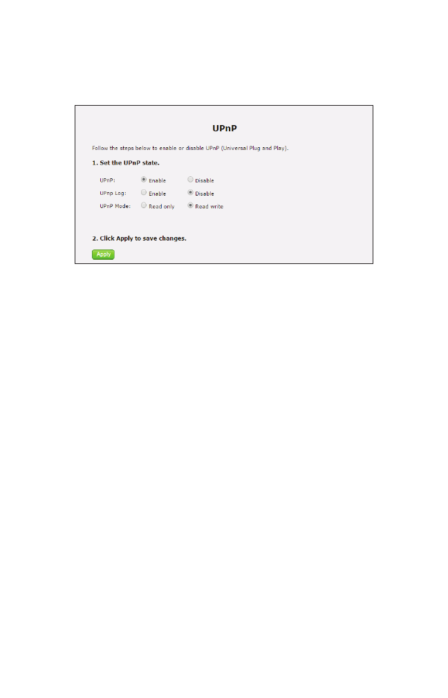
UPnP
Click UPnP from any Firewall screen to generate the UPnP screen, which activates
UPnP (Universal Plug and Play). To activate, set the preferred UPnP options, then
click Apply.
37
Advanced Settings
This chapter explains the options available with the Advanced Setup screens, which
configure some of the more complex settings on the Gateway.
Accessing the Advanced Setup Screens
To access the Gateway’s Advanced Setup screens:
1. Open a Web browser. In the Address text box, type:
http://192.168.0.1
then press Enter on the keyboard.
2. The Gateway’s Main screen appears. Click the Advanced Setup icon.
6
38
T3200BV Gateway
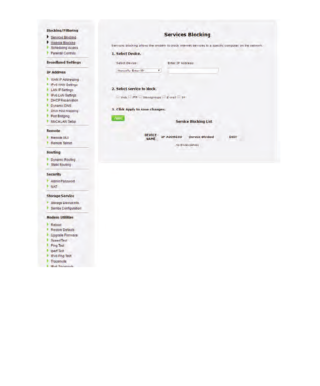
3. The Services Blocking screen appears.
From here, all the Advanced Setup screens can be accessed from the menu on the left.
Services Blocking
Click Services Blocking from any Advanced Setup screen to generate the Services
Blocking screen (see the figure, above). This feature allows the user to block certain
services from accessing the Gateway’s network(s). Follow the onscreen instructions
to configure.
39
Advanced
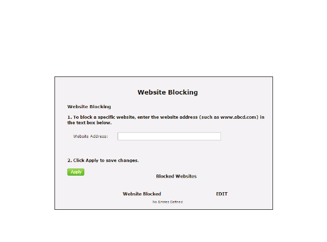
Website Blocking
Click Website Blocking from any Advanced Setup screen to generate the Website
Blocking screen. This feature allows the user to block certain websites from access-
ing the Gateway’s network(s). Follow the onscreen instructions to configure.
40
T3200BV Gateway
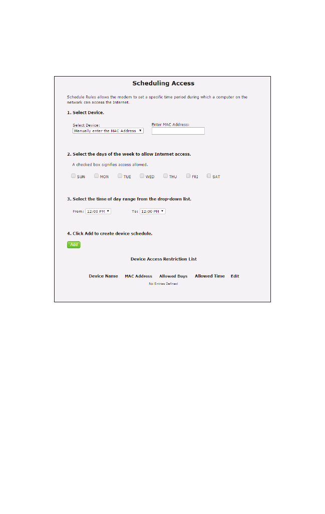
Scheduling Access
Click Scheduling Access from any Advanced Setup screen to generate the Scheduling
Access screen. This feature allows the user to schedule access to the Gateway’s
network(s) for certain devices. Follow the onscreen instructions to configure.
41
Advanced
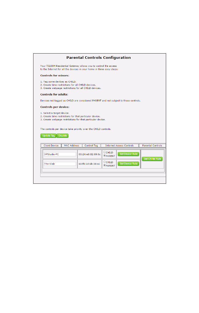
Parental Controls
Click Parental Controls from any Advanced Setup screen to generate the Parental
Controls Configuration screen. This feature allows the user to allow or prevent access
to certain websites for devices on the Gateway’s network. Follow the onscreen instruc-
tions to configure.
42
T3200BV Gateway
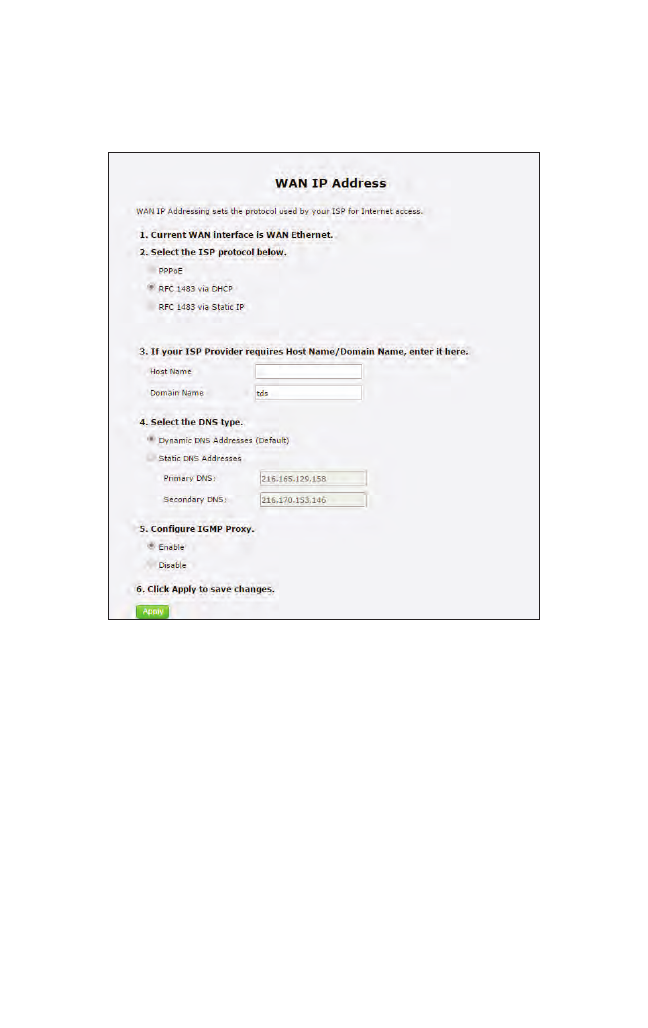
WAN IP Addressing
Click WAN IP Addressing from any Advanced Setup screen to generate the WAN
IP Address screen. This feature allows the user to set the protocol used by the ISP for
Internet access. Follow the onscreen instructions to configure.
43
Advanced
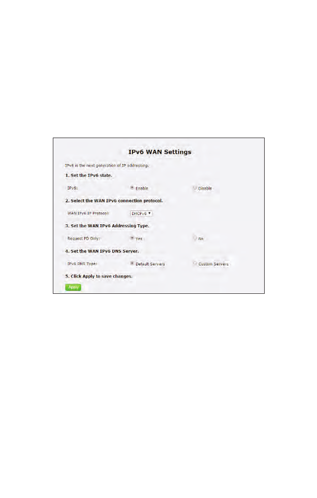
IPv6 WAN Settings
Click IPv6 WAN Settings from any Advanced Setup screen to generate the IPv6
WAN Settings screen. This feature allows the user to set the IPv6 protocol used by the
ISP for Internet access. Follow the onscreen instructions to configure.
WARNING: This setting should be configured by experienced
network technicians only, since any changes could affect the
Gateway’s IPv6 service.
44
T3200BV Gateway
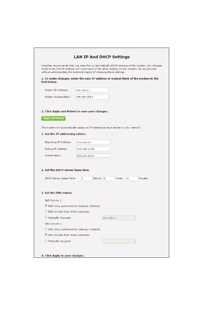
LAN IP Settings
Click LAN IP Settings from any Advanced Setup screen to generate the LAN IP and
DHCP Settings screen. This feature allows the user to set LAN IP and DHCP server
settings on the Gateway. Follow the onscreen instructions to configure.
45
Advanced
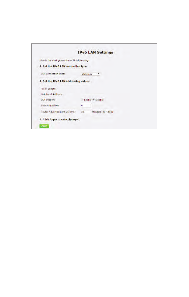
IPv6 LAN Settings
Click IPv6 LAN Settings from any Advanced Setup screen to generate the IPv6 LAN
Settings screen. This feature allows the user to set the IPv6 LAN IP settings on the
Gateway. Follow the onscreen instructions to configure.
46
T3200BV Gateway
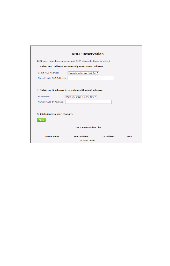
DHCP Reservation
Click DHCP Reservation from any Advanced Setup screen to generate the DHCP
Reservation screen. This feature allows the user to lease a permanent DHCP-
allocated address to a client on the Gateway’s network. Follow the onscreen
instructions to configure.
47
Advanced
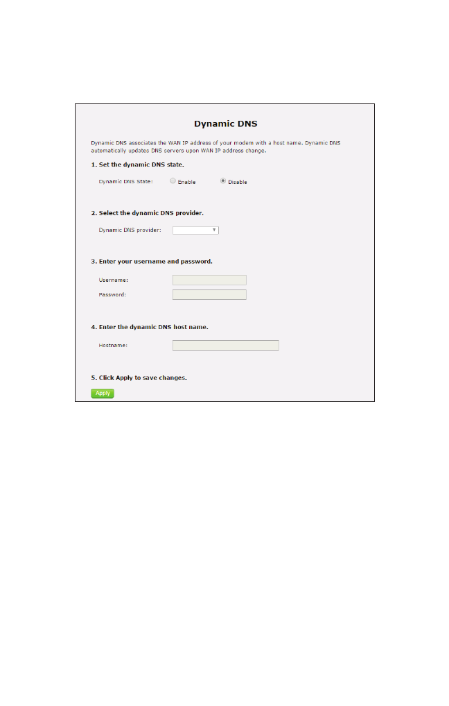
Dynamic DNS
Click Dynamic DNS from any Advanced Setup screen to generate the Dynamic
DNS screen. This feature allows the user to associate the WAN IP address of the
Gateway with a host name. Follow the onscreen instructions to configure.
48
T3200BV Gateway
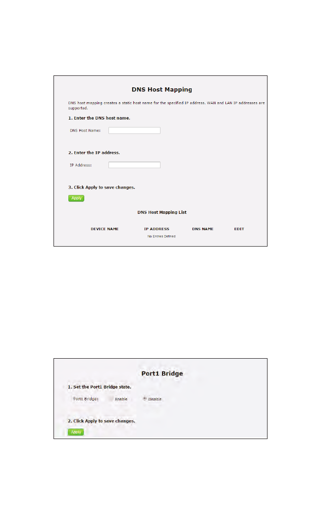
DNS Host Mapping
Click DNS Host Mapping from any Advanced Setup screen to generate the DNS
Host Mapping screen. This feature allows the user to create a static host name for a
specified IP address. Follow the onscreen instructions to configure.
Port Bridging
Click Port Bridging from any Advanced Setup screen to generate the Port1 Bridge
screen. This feature allows the user to create a port bridge, utilizing LAN Port 1, on
the Gateway. Follow the onscreen instructions to configure.
49
Advanced
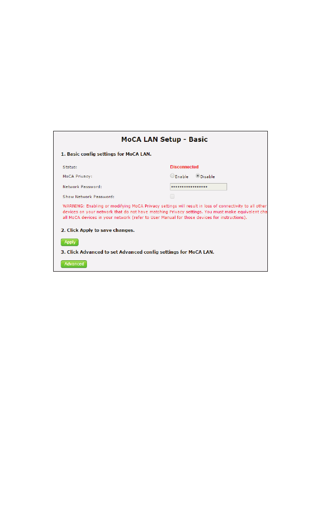
MoCA LAN Setup
Click MoCA LAN Setup from any Advanced Setup screen to generate the MoCA
LAN Setup - Basic screen. This feature allows the user to enable privacy settings on
the Gateway’s MoCA LAN. Follow the onscreen instructions to configure.
WARNING: Enabling or modifying MoCA Privacy Settings will
result in the loss of connectivity to all other MoCA devices on
the network. It is not recommended to make any changes to the
MoCA Settings.
50
T3200BV Gateway
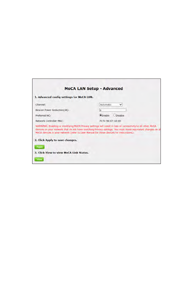
Advanced MoCA LAN
Click Advanced from the MoCA LAN Setup - Basic screen to generate the MoCA
LAN Setup - Advanced screen. This screen allows the user to modify additional
MoCA LAN settings. Follow the onscreen instructions to configure.
WARNING: Enabling or modifying MoCA Privacy Settings will
result in the loss of connectivity to all other MoCA devices on
the network. It is not recommended to make any changes to the
MoCA Settings.
51
Advanced
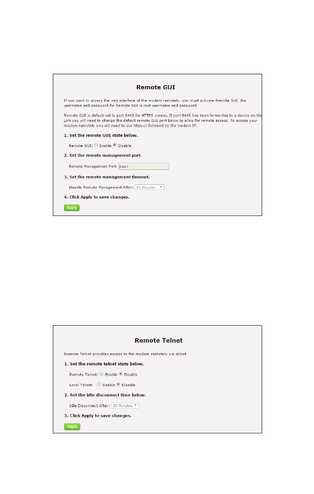
Remote GUI
Click Remote GUI from any Advanced Setup screen to generate the Remote GUI
screen. This feature allows the user to access the Gateway’s graphical user interface
from a remote location. Follow the onscreen instructions to configure.
Remote Telnet
Click Remote Telnet from any Advanced Setup screen to generate the Remote Telnet
screen. This feature allows the user to access the Gateway from a remote location via
telnet. Follow the onscreen instructions to configure.
52
T3200BV Gateway
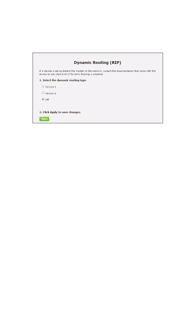
Dynamic Routing
Click Dynamic Routing from any Advanced Setup screen to generate the Dynamic
Routing (RIP) screen. This feature allows the user to set up the Gateway on the net-
work behind a modem using dynamic routing. Follow the onscreen instructions to
configure.
53
Advanced
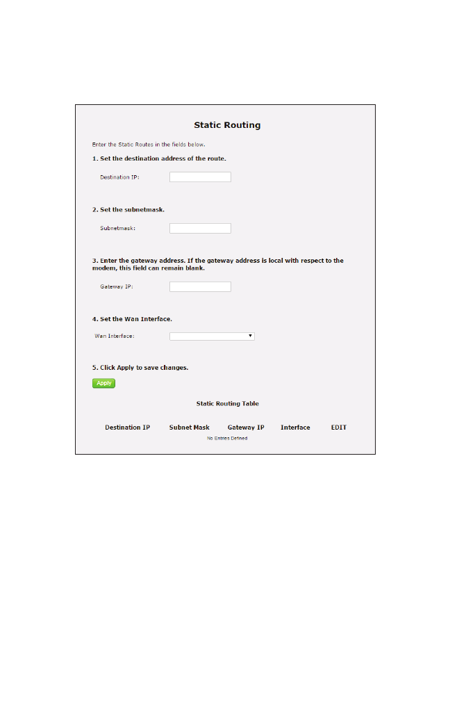
Static Routing
Click Static Routing from any Advanced Setup screen to generate the Static Routing
screen. This feature allows the user to set up the Gateway with static routes. Follow
the onscreen instructions to configure.
54
T3200BV Gateway
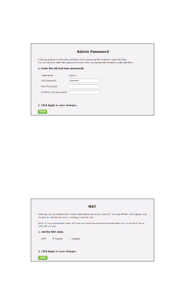
Admin Password
Click Admin Password from any Advanced Setup screen to generate the Admin
Password screen. This feature allows the user to change the password for accessing
the Gateway’s graphical user interface. Follow the onscreen instructions to configure.
NAT
Click NAT from any Advanced Setup screen to generate the NAT screen. Network
addresss translation (NAT) allows the Gateway’s network to use a single IP address to
represent the Gateway’s entire network on the internet.
WARNING: Do not disable NAT on the Gateway unless
instructed to do so by the ISP.
55
Advanced
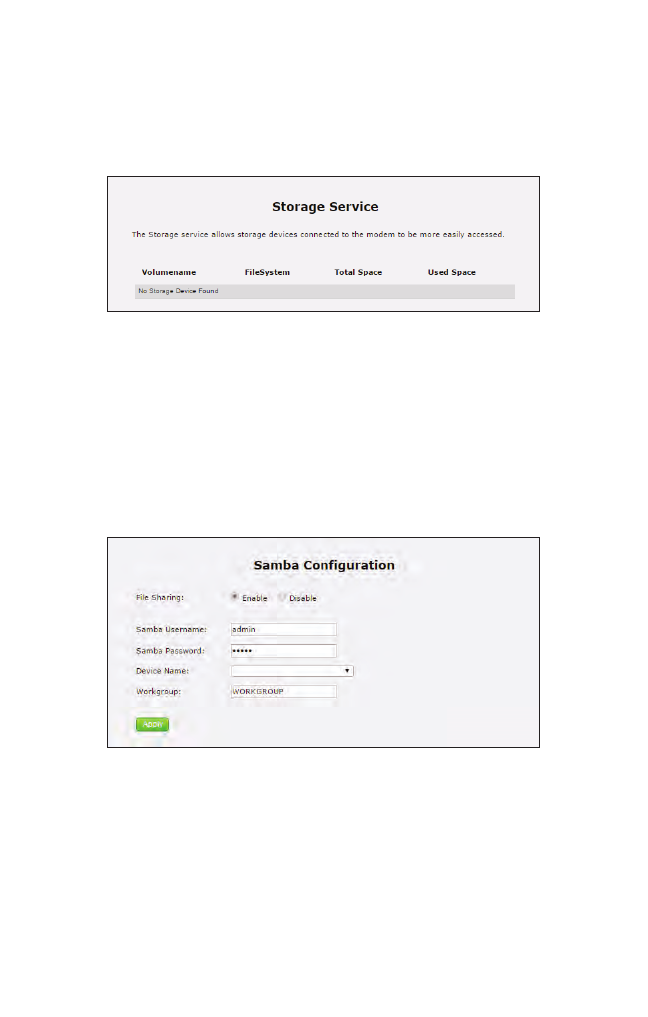
Storage Device Info
Click Storage Device Info from any Advanced Setup screen to generate the Storage
Service screen. This feature allows storage devices connected to the Gateway to be
easily accessed. Any storage devices connected to the Gateway will be listed in the
table at the bottom of the screen.
Samba Configuration
Click Samba Configuration from any Advanced Setup screen to generate the Samba
Configuration screen. This feature allows the user to set up a Samba environment.
Follow the onscreen instructions to configure.
56
T3200BV Gateway
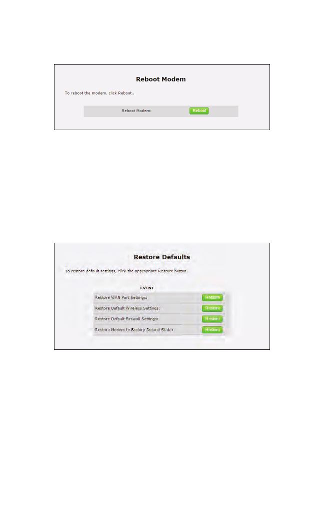
Reboot
Click Reboot from any Advanced Setup screen to generate the Reboot screen. Reboot
the Gateway by clicking Reboot.
Restore Defaults
Click Restore Defaults from any Advanced Setup screen to generate the Restore
Defaults screen. To restore certain settings on the Gateway, click the appropriate
Restore button.
57
Advanced
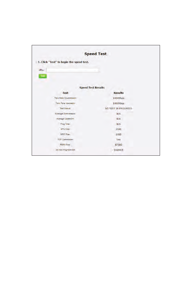
Speed Test
Click Speed Test from any Advanced Setup screen to generate the Speed Test screen.
This screen allows the user to perform a speed test on the Gateway’s Internet (or
WAN) connection. Enter the URL for a server at a speed test site, then click Test.
58
T3200BV Gateway
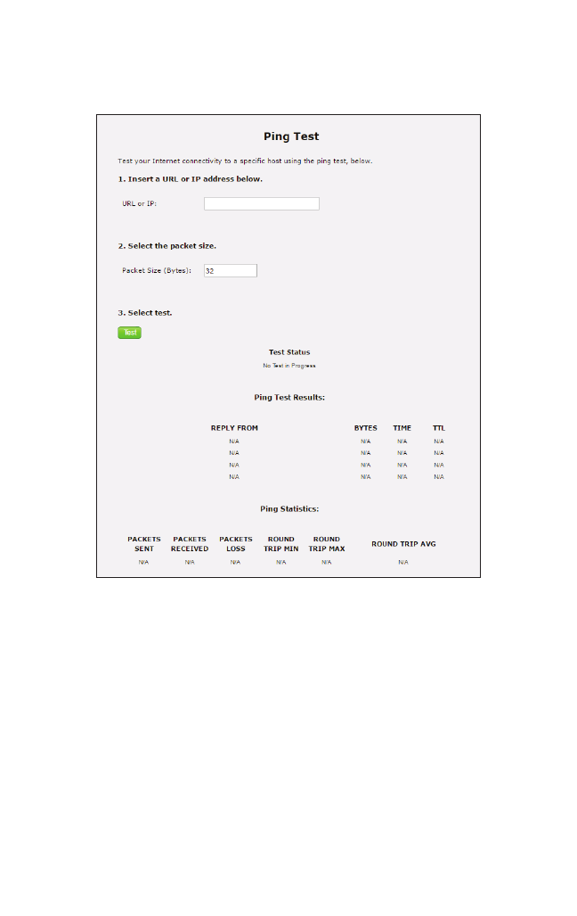
Ping Test
Click Ping Test from any Advanced Setup screen to generate the Ping Test screen. To
perform a ping test on the Gateway, follow the onscreen instructions.
59
Advanced
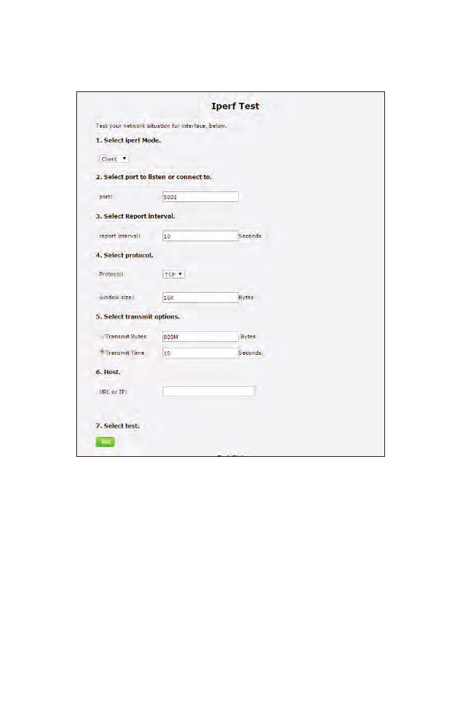
Iperf Test
Click Iperf Test from any Advanced Setup screen to generate the Iperf Test screen. To
perform an iperf test on the Gateway, follow the onscreen instructions.
60
T3200BV Gateway
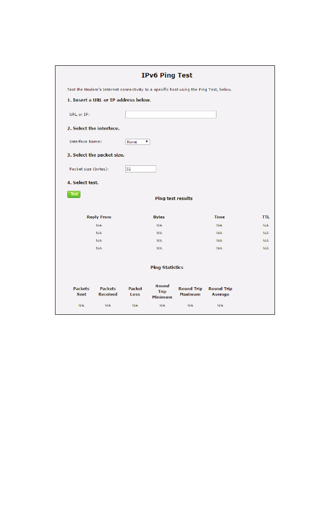
IPv6 Ping Test
Click IPv6 Ping Test from any Advanced Setup screen to generate the IPv6 PingTest
screen. To perform an IPv6 ping test on the Gateway, follow the onscreen instructions.
61
Advanced
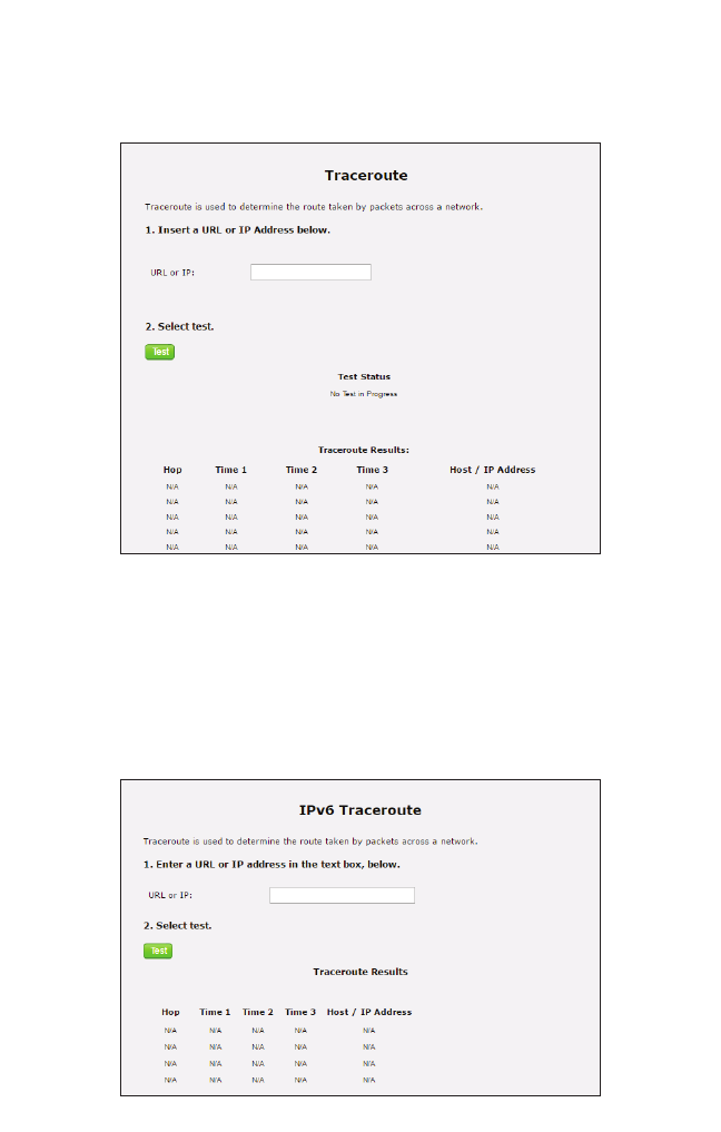
Traceroute
Click Traceroute from any Advanced Setup screen to generate the Traceroute screen.
To perform an route trace on the Gateway, follow the onscreen instructions.
IPv6 Traceroute
Click IPv6 Traceroute from any Advanced Setup screen to generate the IPv6
Traceroute screen. To perform an IPv6 route trace on the Gateway, follow the onscreen
instructions.
62
T3200BV Gateway
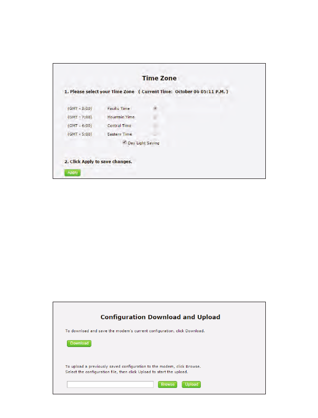
Time Zone
Click Time Zone from any Advanced Setup screen to generate the Time Zone screen.
Use this screen to set the time zone on the Gateway.
Config Download/Upload
Click Config Download/Upload from any Advanced Setup screen to generate the
Configuration Download and Upload screen. Use this screen to save the Gateway’s
current configuration and settings, or upload a previously saved configuration file
onto the Gateway.
63
Advanced
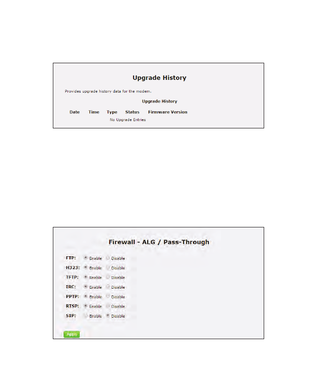
Upgrade History
Click Upgrade History from any Advanced Setup screen to generate the Upgrade
History screen. This screen displays a list of firmware upgrades applied to the Gateway.
ALG
Click ALG from any Advanced Setup screen to generate the Firwall - ALG / Pass-
Through screen. This screen allows the user to configure ALG settings on the Gateway.
64
T3200BV Gateway
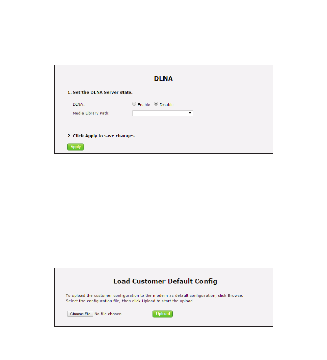
DLNA
Click DLNA from any Advanced Setup screen to generate the DLNA screen. This
screen allows the user to configure DLNA settings on the Gateway.
Load Customer Default Config
Click Load Customer Default Config from any Advanced Setup screen to generate
the Load Customer Default Config screen. This screen allows the user to load the cus-
tomer’s configuraton as the default configuration on the Gateway.
65
Advanced
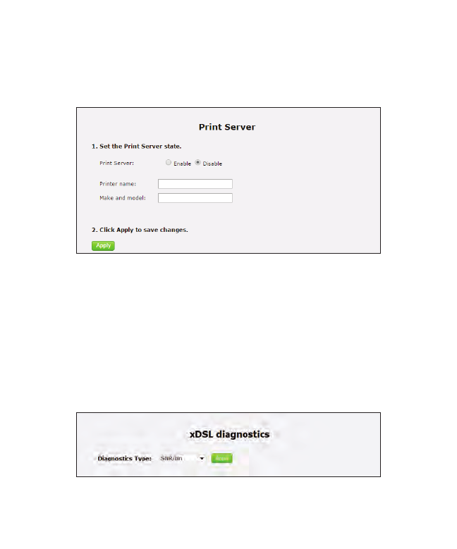
Print Server
Click Print Server from any Advanced Setup screen to generate the Print Server
screen. This screen allows the user to select and configure a print server for the
Gateway’s network.
xDSL Diagnostics
Click xDSL diagnostics from any Advanced Setup screen to generate the xDSL
Diagnostics screen. This screen allows the user to select a type of diagnostics on the
Gateway.

70
Specifications
General
Model Number(s)
T3200BV (Wireless 11ac Bonded VDSL2 Modem Gateway)
Standards
IEEE 802.3 (10BaseT)
IEEE 802.3u (100BaseTX)
IEEE 802.11 b, g, n, ac (Wireless)
G.dmt
G.lite
t1.413
RFC 1483, 2364, 2516
Protocol
LAN - CSMA/CD
WA N - PPP, DHCP, Static IP
WAN
VDSL2 interface
LAN
10/100/1000 RJ-45 switched ports
Speed
LAN Ethernet: 10/100/1000 Mbps auto-sensing
Wireless: 802.11a, b, g, n, ac; 900 Mbps optimal (see Wireless Operating Range
for details)
A

71
T3200BV Gateway
Cabling Type
Ethernet 10BaseT: UTP/STP Category 3 or 5
Ethernet100BaseTX: UTP/STP Category 5
Wireless Operating Range
Indoors
Up to 91M (300 ft.) @ 300 Mbps
Outdoors
Up to 457M (1500 ft.) @ 300 Mbps
Topology
Star (Ethernet)
LED Indicators
WAN, Wireless, and WPS Push Button
Power Adapter
Model No. - CDS036-W120U
Input - 100-240V~, 50/60Hz, 1.0A
Output - 12.0V, 3.0A
Manufacturer - Adapter Technology Co Ltd
This product is intended to be used with UL Listed Power Adapter # CDS036-
W120U with LPS and an operating temperature up to 45 degree C, and below an
altitude of 2000 meters. If you need further assistance or information, please
contact Actiontec.

72
Specifications
Environmental
Power
External, 12V DC, 3A
Certifications
FCC Part 15 Class B, Class C and E, FCC Part 68, UL
Operating Temperature
0º C to 45º C (32ºF to 113ºF)
Storage Temperature
-20ºC to 70ºC (-4ºF to 158ºF)
Operating Humidity
10% to 85% non-condensing
Storage Humidity
5% to 90% non-condensing

69
Notices
Warranty
This product has a one-year Limited Hardware Warranty and 90-day free software
updates from date of purchase.
Local Law
This Limited Warranty Statement gives the customer specific legal rights. The
customer may also have other rights, which vary from state to state in the United
States, and from country to country elsewhere in the world.
To the extent that this Limited Warranty Statement is inconsistent with local
law, this Statement shall be deemed modified to be consistent with such local
law. Under such local law, certain disclaimers and limitations of this Warranty
Statement may not apply to the customer.
Go to http://www.actiontec.com/products/warranty.php for more information.
Important Safety Instructions
Basic safety precautions should always be followed to reduce the risk of fire, electri-
cal shock, and personal injury, including the following:
• Do not use this product near water – for example, near a bathtub, kitchen
sink, laundry tub, or swimming pool, or in a wet basement; only clean with
dry cloth.
• Do not block any ventilation openings. Install in accordance with the
manufacturer’s instructions. Do not install near any heat sources such as
radiators, heat registers, stoves, or other apparatus including amplifiers that
produce heat.
• Do not use the telephone to report a gas leak in the vicinity of the leak.
• Use only the power cord indicated in this manual.

70
Notices
Coaxial Cable
If applicable, the coaxial cable screen shield needs to be connected to the Earth at
the building entrance per ANSI/NFPA 70, the National Electrical Code (NEC),
in particular Section 820.93, “Grounding of Outer Conductive Shield of a Coaxial
Cable,” or in accordance with local regulation.
FCC Class B Equipment
This equipment has been tested and found to comply with the limits for a Class B
digital device, pursuant to Part 15 of the FCC Rules. These limits are designed to
provide reasonable protection against harmful interference in a residential installa-
tion. This equipment generates, uses and can radiate radio frequency energy and,
if not installed and used in accordance with the instructions, may cause harmful
interference to radio communications. However, there is no guarantee that inter-
ference will not occur in a particular installation. If this equipment does cause
harmful interference to radio or television reception, which can be determined by
turning the equipment off and on, the user is encouraged to try and correct the
interference by implementing one or more of the following measures:
• Reorient or relocate the device;
• Increase the separation between the equipment and receiver;
• Consult the dealer or an experienced radio or television technician for help.
Modifications
The FCC requires the user to be notified that any changes or modifications made
to this device that are not expressly approved by Actiontec Electronics, Inc, may
void the user’s authority to operate the equipment.

71
Notices
Declaration of Conformity for Products Marked With the FCC Logo
This device complies with part 15 of the FCC. Operation is subject to the following
two conditions:
1. This device may not cause harmful interference;
2. This device must accept any interference received, including interference that
may cause undesired operation of the device.
Important Note on Wi-Fi
If applicable, this equipment complies with FCC radiation exposure limits set forth
for an uncontrolled environment.
The radio has been found to be compliant to the requirements set forth in CFR 47
Sections 2.1091, 15.247 (b) (4),15.407 addressing RF Exposure from radio frequen-
cy devices as defined in Evaluating Compliance with FCC Guidelines for Human
Exposure to Radio Frequency Electromagnetic Fields. The equipment should be
installed more than 30 cm (~12 in.) from your body or nearby persons.
For product available in the USA market, only channel 1~11 can be operated.
Selection of other channels is not possible.
The device could automatically discontinue transmission in case of absence of
information to transmit, or operational failure. Note that this is not intended to
prohibit transmission of control or signaling information or the use of repetitive
codes where required by the technology.
The device for the band 5150-5250 MHz is only for indoor usage to reduce poten-
tial for harmful interference to co-channel mobile satellite systems.
The maximum antenna gain permitted for devices in the band 5725-5825 MHz
shall comp with the e.i.r.p. limits specified for point-to-point and non point-to-
point operation as appropriate.
The transmitter must not be co-located or operating in conjunction with any other
antenna or transmitter.

72
T3200M Gateway
FCC Part 68 User Manual Information
This equipment complies with Part 68 of the FCC rules. Located on the equip-
ment is a label that contains, among other information, the ACTA registration
number and ringer equivalence number (REN.) If requested, this information must
be provided to the telephone company.
The REN is used to determine the quantity of devices which may be connected to
the telephone line. Excessive REN’s on the telephone line may result in the devices
not ringing in response to an incoming call. In most, but not all areas, the sum of
the REN’s should not exceed five (5.0). To be certain of the number of devices that
may be connected to the line, as determined by the total REN’s contact the tele-
phone company to determine the maximum REN for the calling area.
This equipment cannot be used on the telephone company-provided coin service.
Connection to Party Line Service is subject to State Tariffs.
If this equipment causes harm to the telephone network, the telephone com-
pany will notify you in advance that temporary discontinuance of service may be
required. If advance notice isn’t practical, the telephone company will notify the
customer as soon as possible. Also, you will be advised of your right the file a
complaint with the FCC if you believe it is necessary.
The telephone company may make changes in its facilities, equipment, operations,
or procedures that could affect the operation of the equipment. If this happens, the
telephone company will provide advance notice in order for you to make the nec-
essary modifications in order to maintain uninterrupted service.
If trouble is experienced with this equipment, please contact:
Company Name:
Address:
TEL:
FAX:
Actiontec Electronics, Inc.
760 N. Mary Ave., Sunnyvale, CA 94085
(408) 752-7700
(408) 541-9003
If the trouble is causing harm to the telephone network, the telephone company
may request you to remove the equipment from the network until the problem is
resolved.
This equipment uses the following USOC jacks: RJ14
It is recommended that the customer install an AC surge arrester in the AC outlet
to which this device is connected. This is to avoid damaging the equipment caused
by local lightening strikes and other electrical surges.