Active RFID Systems GP-RWT Infrared triggered part 15 transmitter User Manual
Active RFID Systems, Inc. Infrared triggered part 15 transmitter Users Manual
Users Manual

ARS
Active RFID Systems, Inc
RFID System Evaluation Kit
Instruction Manual
Version 103105
The information contained in this document is the sole property of Active RFID Systems, Inc. and cannot be disclosed
to third parties without our expressed written permission. It is provided for your use in conjunction with the Active
RFID Systems supplied RFID system only.

ARS - Active RFID Systems, Inc.
Active RFID Systems - Evaluation Kit Instruction Manual - Version 103105 Page 2 of 35
Contents
1. RFID EVALUATION KIT DESCRIPTION ...................................................................................................... 4
1
1.
.1
1.
. EVALUATION KIT COMPONENTS................................................................................................................. 4
1
1.
.2
2.
. EVALUATION KIT FUNCTIONAL DESCRIPTION.............................................................................................. 5
1
1.
.3
3.
. EZ READER SOFTWARE ........................................................................................................................... 6
1
1.
.4
4.
. ACTIVE TAGS ........................................................................................................................................... 6
1
1.
.5
5.
. EASY-TRAK TRIGGER ............................................................................................................................... 6
1
1.
.6
6.
. EASY-TRAK READER ................................................................................................................................6
1
1.
.7
7.
. ANTI-COLLISION TAGS EXPLAINED ............................................................................................................ 6
2. SYSTEM REQUIREMENTS........................................................................................................................... 6
3. INSTALLATION AND CONFIGURATION INSTRUCTIONS......................................................................... 7
3
3.
.1
1.
. HARDWARE INSTALLATION ........................................................................................................................ 7
3.1.1. Connecting the Easy-Trak Reader to the PC .................................................................................... 7
3.1.2. Connecting the Easy-Trak Trigger to the PC .................................................................................... 7
3
3.
.2
2.
. SOFTWARE INSTALLATION AND CONFIGURATION ........................................................................................ 8
3.2.1. Installing the .NET Framework on the PC .........................................................................................8
3.2.2. Configuring the Network Connection................................................................................................. 8
3.2.3. Determining Which Serial Port is Being Used ................................................................................... 9
3.2.4. Installing the EZ Reader Software on the PC.................................................................................. 10
3.2.5. Configuring the EZ Reader Software Settings ................................................................................ 11
3.2.5.1. Configuring the Serial Port for the Trigger ............................................................................................. 11
3.2.5.2. Configuring the IP Address for the Reader Used as a Trigger .............................................................. 12
3.2.6. Loading the Optional Tag Memory Map .......................................................................................... 13
4. USING THE EVALUATION KIT................................................................................................................... 14
4
4.
.1
1.
. EVALUATION KIT CONFIGURATIONS ......................................................................................................... 15
4.1.1. Example. Functionality of One System Configuration .................................................................... 16
4.1.2. Easy-Trak Trigger Handheld Modes................................................................................................16
4.1.2.1. Mode 1 - Last Command Memory Mode. ..............................................................................................17
4.1.2.2. Mode 2 - Low Power Singe Tag Mode .................................................................................................. 17
4.1.2.3. Mode 4 - 24 Tag Anti-Collision Mode .................................................................................................... 17
4.1.2.4. Mode 5 - Beacon On ............................................................................................................................. 17
4.1.2.5. Mode 6 - Beacon Off ............................................................................................................................. 18
4.1.3. Changing the Easy Trak Trigger Modes.......................................................................................... 18
4
4.
.2
2.
. EXAMPLES. RUNNING THE EVALUATION KIT ............................................................................................ 18
4.2.1. Reading Data From Tags ................................................................................................................ 18
4.2.1.1. Easy-Trak Trigger Used as Serial Device - Tags Respond with RF to Reader ..................................... 18
4.2.1.2. Easy-Trak Trigger Used as a Handheld Device - Tags Respond with RF to Reader ............................ 18
4.2.1.3. Easy-Trak Trigger Used as a Serial Device - Tags Respond with IR to Trigger .................................... 19
4.2.2. Writing Data to Tags........................................................................................................................ 19
4.2.2.1. Easy-Trak Trigger Used as Serial Device - Read/Write to Tags With IR............................................... 19
4.2.2.2. Easy-Trak Trigger Used as Serial Device - Read RF and Write IR ....................................................... 19
4
4.
.3
3.
. REVIEW OF EASY READER SOFTWARE SCREENS AND FUNCTIONALITY...................................................... 20
4.3.1. Responses Screen .......................................................................................................................... 21
4.3.2. Tag Data Screen.............................................................................................................................. 23
4.3.3. Search Screen ................................................................................................................................. 25
4.3.4. Tag Configuration Screen................................................................................................................ 27
4.3.5. Beacon Ctrl Screen ......................................................................................................................... 28
4.3.6. Temperature Screen........................................................................................................................ 29
4.3.7. Debugger Screen ............................................................................................................................ 30
4.3.8. Configuration Screen....................................................................................................................... 31
A.1 INSTALLING THE USB/SERIAL CABLE ADAPTER AND DRIVER (OPTIONAL) ............................... 33

ARS - Active RFID Systems, Inc.
Active RFID Systems - Evaluation Kit Instruction Manual - Version 103105 Page 3 of 35
List of Figures
Figure 1 - Evaluation Kit Components ..................................................................................... 5
Figure 2 - TCP/IP Properties ................................................................................................... 9
Figure 3 - System Properties ................................................................................................. 10
Figure 4 - Device Manager Window ...................................................................................... 10
Figure 5 - Serial Port Settings................................................................................................ 12
Figure 6 - IP Address............................................................................................................. 13
Figure 7 - Typical Desktop Setup .......................................................................................... 15
Figure 8 - Responses Screen ................................................................................................ 21
Figure 9 - Tag Data Screen ................................................................................................... 23
Figure 10 - Debugger Screen ................................................................................................ 30
Figure 11 - Configuration Screen........................................................................................... 31
List of Tables
Table 1 - Evaluation Kit Configurations ................................................................................. 15
Table 2 - Trigger Handheld Modes ........................................................................................ 17
Table 3 - Responses Screen ................................................................................................. 21
Table 4 - Tag Data Screen .................................................................................................... 23
Table 5 - Search Screen........................................................................................................ 25
Table 6 - Beacon Control Screen .......................................................................................... 28
Table 7 - Temperature Screen............................................................................................... 29
Table 8 - Configuration Screen.............................................................................................. 31

ARS - Active RFID Systems, Inc.
Active RFID Systems - Evaluation Kit Instruction Manual - Version 103105 Page 4 of 35
1. RFID Evaluation Kit Description
Please note that the RFID Evaluation Kit is a fully functional system, however, it is
intended to demonstrate first principles only. Our industrial versions offer enhanced
performance by virtue of greater RF range, improved anti-collision response and
waterproof enclosures. The kit is designed for evaluation of the effectiveness and
functionality of active RFID and the RFID system components, as well as to enable
development of a final product specification that will lead to a production system that
will satisfy specific requirements.
RF Systems are, by their nature, subject to outside interference sources. For
example, laptop computers, welders, ham radios, and wireless weather stations can all
interfere with RFID systems. Range and reliability can be affected by these sources.
Therefore, as a standard precaution and to optimize performance, it is recommended that
the Reader be placed as far from a laptop or other potential sources of interference
as possible.
This equipment has been tested and found to comply with the limits for a Class A
digital device, pursuant to Part 15 of the FCC Rules. These limits are designed to provide
reasonable protection against harmful interference when the equipment is operated in a
commercial environment. This equipment generates, uses, and can radiate radio
frequency energy and, if not installed and used in accordance with the instruction manual,
may cause harmful interference to radio communications. Operation of this equipment in a
residential area is likely to cause harmful interference in which case the user will be
required to correct the interference at his own expense. Changes or modifications not
expressly approved by the party responsible for compliance could void the user's authority
to operate the equipment.
1
1.
.1
1.
.
Evaluation Kit Components
The Active RFID Systems RFID Evaluation Kit includes the following components:
One Easy-Trak Reader, antenna, and power adapter
One Easy-Trak Trigger
ARS Active Tags
USB to Serial Adapter
Serial Cable
Network Crossover Cable
Application CD containing the EZ Reader Software, optional memory Tag
memory map, Microsoft .NET web services framework, USB to Serial drivers,
and this manual.
ARS - Active RFID Systems, Inc.
Active RFID Systems - Evaluation Kit Instruction Manual - Version 103105 Page 5 of 35
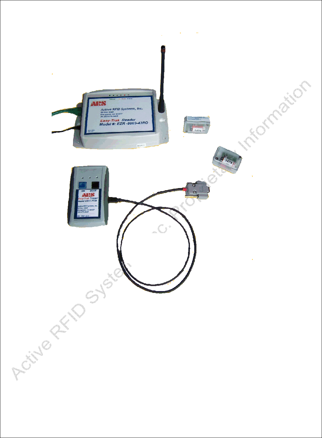
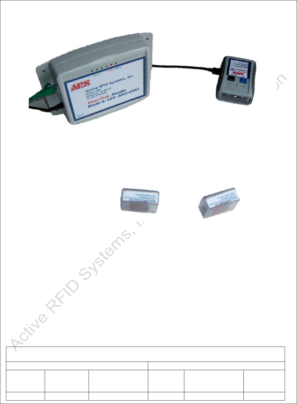
Figure 1 - Evaluation Kit Components
1
1.
.2
2.
.
Evaluation Kit Functional Description
The Active RFID Systems Evaluation Kit is a fully functional RFID system that includes a
Reader, Tag Trigger, Active RFID Tags, and PC Software that can be used to read, write,
and display Tag data. The Kit components are described below.
Custom
Serial
Cable
Easy-Trak
Reader
Active Tags
Easy-Trak
Trigger

ARS - Active RFID Systems, Inc.
Active RFID Systems - Evaluation Kit Instruction Manual - Version 103105 Page 6 of 35
1
1.
.3
3.
.
EZ Reader Software
The EZ Reader Software provides a user interface and display and is used to trigger,
read, write, and configure Tags by controlling the Trigger and Reader.
1
1.
.4
4.
.
Active Tags
Active Tags incorporate the unique (patent pending) ability to communicate via dual mode
Radio Frequency (RF) and Infrared (IR). Tags are triggered (i.e. forced to respond) via IR
using an Easy-Trak Trigger or Reader. Tags can be configured to respond to a trigger
with IR, RF, or both. Tags can also be set to 'beacon', i.e. transmit RF at fixed intervals
without a trigger. Active RFID Systems Tags incorporate anti-collision technology that
optimizes the successful reception when more than one Tag is triggered. See Section 1.7.
1
1.
.5
5.
.
Easy-Trak Trigger
Easy-Trak Trigger has two modes of operation, as a manual IR trigger, and for two-way
IR communication when connected to a PC via the supplied, custom, serial cable.
1
1.
.6
6.
.
Easy-Trak Reader
Easy-Trak Readers are Ethernet-enabled and can be directly connected to a PC with the
supplied crossover cable. Readers receive data from Tags via RF and can trigger Tags
via IR. (note: industrial readers can both “read” and “write” data to and from tags via the
infra-red mode) The Reader includes an audible enunciator that will chirp on the first RF
reception of any particular ID value.
1
1.
.7
7.
.
Anti-Collision Tags Explained
The term Anti-collision refers to the communications protocol/scheme that is utilized in
order to optimize the successful reception of multiple Tags. Because Tags can interfere
with each other if they respond to a Trigger at the same time, an anti-collision algorithm is
used to randomize Tag responses within 'windows' of time. This increases the likelihood
of all Tag responses getting through intact. The exact number, size, and timing of
windows are chosen based on the number of Tags that are expected to respond to a
Trigger. The Anti-collision algorithm data are sent within the IR Trigger signal to the Tags
and the Tags use that to calculate when to respond. Of course the larger the expected
number of Tags, the longer the time required to guarantee 100% reception.
2. System Requirements

ARS - Active RFID Systems, Inc.
Active RFID Systems - Evaluation Kit Instruction Manual - Version 103105 Page 7 of 35
The Active RFID Systems Evaluation Kit requires the following:
A PC running Windows 2000 or XP.
An Ethernet port on the PC.
A Serial or USB port on the PC.
Access to a standard 120 volt outlet for the Reader power adapter.
3. Installation and Configuration Instructions
The following sections describe installation and configuration of the hardware and software
components of the Evaluation Kit. The steps should be executed in the order shown.
3
3.
.1
1.
.
Hardware Installation
3.1.1. Connecting the Easy-Trak Reader to the PC
1. If the supplied Antenna is not attached to the Easy-Trak Reader, gently screw the
right angle connector into the Reader and then screw the antenna onto the
connector. Orient the antenna so it is 'vertical', e.g. perpendicular to the Reader if
the Reader is sitting on a table. See Figure 1.
2. Plug the Power Adapter into a standard outlet and plug the power cable into the
Easy-Trak Reader. The Red “Power” LED should light.
3. Plug the Crossover cable into the PC and into the Reader. The Green “Ethernet”
LED should light.
4. The Reader is ready for use.
3.1.2. Connecting the Easy-Trak Trigger to the PC
Note that the Easy-Trak Trigger can also be used as a handheld device. Section 4.1.2
reviews the Software functionality and the various Trigger modes available.
1. Plug the Custom Serial Cable into to the 9-pin Serial connector on the PC. If the
PC does not have a Serial Port, the optional USB/Serial Cable Adapter must be
used. See Appendix 1 for USB/Serial Cable Adapter and Driver installation
instructions.
2. If the USB/Serial Cable is being used, plug the 9-pin Serial Cable connector into
the USB/Serial Cable and plug the USB connector into the PC.
Always plug the USB cable into the same USB port on the PC. As noted in the
installation instructions, the Serial Port (Com Port) will change if a different USB port is
used. Refer to Sections 3.2.3 and 3.2.5 to determine which Serial Port is being used
and how to configure the EZ Reader Software for a different Serial Port.
3. Plug the Serial Cable into the Easy-Trak Trigger. All three Red LEDs on the
trigger assembly should light.

ARS - Active RFID Systems, Inc.
Active RFID Systems - Evaluation Kit Instruction Manual - Version 103105 Page 8 of 35
4. Follow the instructions in Section 3.2.5.1 to configure the EZ Reader Software for use
with the Easy-Trak Trigger connected to the Serial Port.
3
3.
.2
2.
.
Software Installation and Configuration
The CD provided with the Evaluation Kit contains the following files:
EZ Reader Application (EZ Reader Vxx.exe)
Tag Memory Map (memmapsm.xml)
Microsoft .NET web services framework (DOTNETFX.EXE)
USB to Serial Adapter drivers
Evaluation Kit Manual (Evaluation Kit Instruction Manual 0805.1.pdf)
3.2.1. Installing the .NET Framework on the PC
The PC must have the .NET Framework installed. Execute the following steps to install
.NET on the PC. Note that the most recent version of the .NET Framework can also be
downloaded from the Microsoft website.
1. Put the CD in the PC and access the files.
2. Run DOTNETFX.EXE by double clicking on the filename. The installer should start.
3. A dialog box will ask if you want to install the .NET Framework. Click the 'YES'
button to proceed.
4. The dialog boxes will disappear when the installation is complete.
3.2.2. Configuring the Network Connection
Open the 'Network Connections' folder by either of the following methods:
1. Right Click on the 'My Network Places' icon on the Desktop and selecting
'Properties'
Or
Open 'Control Panel' by clicking on the 'Start' button and selecting 'Settings', then
double click on 'Control Panel'. Double click on 'Network Connections'.
2. Right click on 'Local Area Connections' and select 'Properties'.
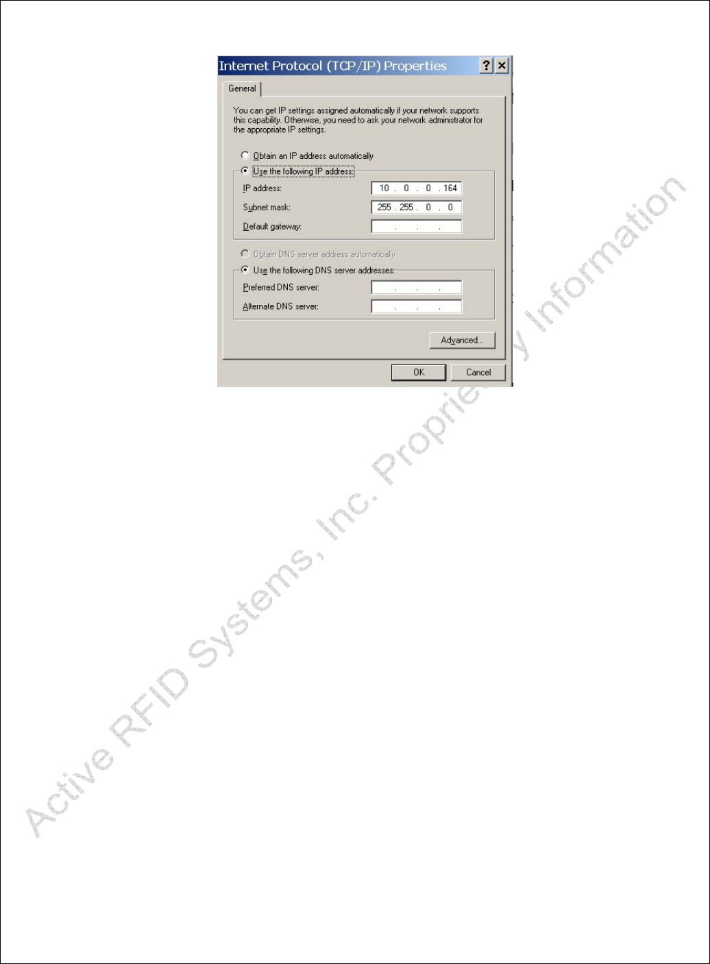
3. Under the 'General' tab double click 'Internet Protocol (TCP/IP)'.
4. Select 'Use the following IP address'.
5. Enter the IP Address as 10.0.0.164.
6. Enter the Subnet mask as 255.255.0.0.
7. The Internet Properties dialog should look like Error! Reference source not found.
when you are finished.
8. Click OK to accept the changes and click OK again to close the Local Area
Connection Properties dialog.
ARS - Active RFID Systems, Inc.
Active RFID Systems - Evaluation Kit Instruction Manual - Version 103105 Page 9 of 35
Figure 2 - TCP/IP Properties
3.2.3. Determining Which Serial Port is Being Used
The EZ Reader Software must be configured to use the appropriate serial port (i.e. to
establish communications with the Easy-Trak Trigger). The following procedure should be
used to determine which serial port is connected to the Trigger. The EX Reader Software
will be configured in Section 3.2.
1. Open Control Panel (Click on the 'Start' button and select 'Settings' and 'Control
Panel').
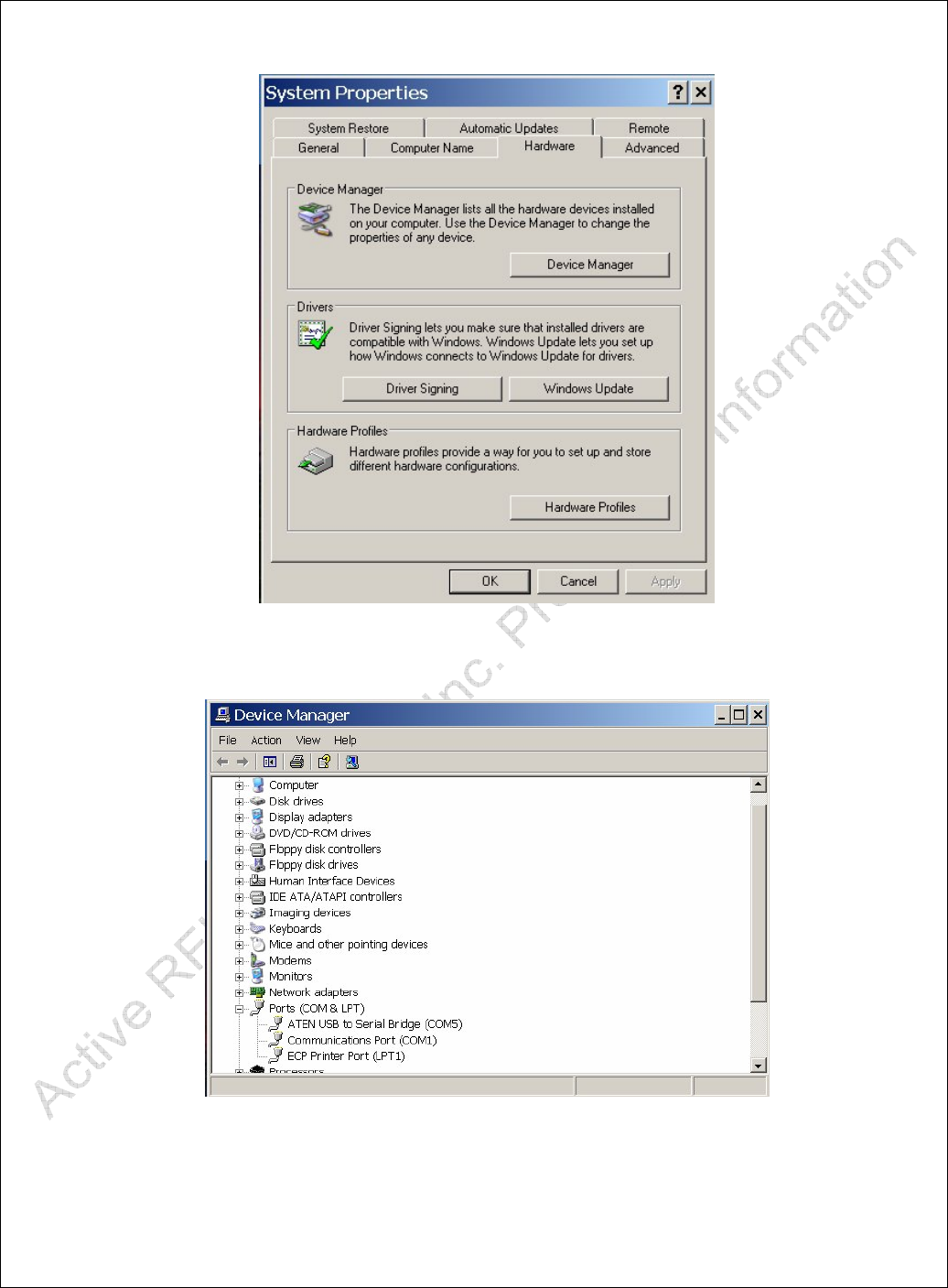
2. Open 'System' and click on the 'Hardware' tab. The 'System Properties' Dialog
should appear and look like Error! Reference source not found.
3. Click the 'Device Manager' button. Then click on the 'plus sign' next to 'Ports'.
The Device Manager screen should look like Error! Reference source not found..
4. Note which 'Communications Port' number is displayed (e.g. COM1 is port 1).
This number will be used to configure the EZ Reader software.
5. If the USB/Serial Adapter is being used, the number displayed on the 'ATEN USB
to Serial Bridge' should be used instead.
6. Close the 'Device Manager' window, click 'OK' in the 'System Properties' Dialog
and close the 'Control Panel' window if necessary.
ARS - Active RFID Systems, Inc.
Active RFID Systems - Evaluation Kit Instruction Manual - Version 103105 Page 10 of 35
Figure 3 - System Properties
Figure 4 - Device Manager Window
3.2.4. Installing the EZ Reader Software on the PC

ARS - Active RFID Systems, Inc.
Active RFID Systems - Evaluation Kit Instruction Manual - Version 103105 Page 11 of 35
Access the CD files and copy the EZ Reader application (EZ Reader Vxx.exe) to the
Desktop. The EZ Reader application includes a default Tag Memory Map. If an
alternative Memory Map file (memmapsm.xml) is supplied, copy that file to the Desktop.
Note that it is convenient to copy the files to the Desktop, but they can be put in any
appropriate folder.
3.2.5. Configuring the EZ Reader Software Settings
3.2.5.1. Configuring the Serial Port for the Trigger
The EZ Reader Software must be configured to communicate with the Easy Trak
Trigger via the appropriate Serial Port. Follow the steps outlined below to configure the
software.
1. Open the EZ Reader Software (double click on the ARS EZ Reader icon).
2. Click on the Configuration Tab.
3. Change the number of the Com Port to the number of the Serial (Com) port
determined in Section 3.2.3.
4. Pull down the Trigger Address menu and select Serial.
5. The rest of the Configuration Settings should be the same as those shown in Error!
Reference source not found..
ARS - Active RFID Systems, Inc.
Active RFID Systems - Evaluation Kit Instruction Manual - Version 103105 Page 12 of 35
Figure 5 - Serial Port Settings
3.2.5.2. Configuring the IP Address for the Reader Used as a Trigger
The Easy-Trak Reader includes an IR emitter that can function as a Trigger. To use the
Reader as a Trigger the EZ Reader Software must be configured to communicate with the
Reader as a Trigger. Note that the Reader will function as a receiver for RF returned by
the Tags even if it is not configured or used as a Trigger. Follow the steps outlined below
to enable the Reader as a Trigger.
1. Be sure the Network Connection is configured as described in Section 3.2.2.
2. Connect the Easy-Trak Reader to the PC with the network cable and apply power to
the Reader.
3. Note the IP Address listed on the label on the Reader (e.g. 10.0.0.30).
ARS - Active RFID Systems, Inc.
Active RFID Systems - Evaluation Kit Instruction Manual - Version 103105 Page 13 of 35
4. Open the EZ Reader Software (double click on the ARS EZ Reader icon).
5. Click on the Configuration Tab.
6. Click the 'Look for Readers' button.
7. Pull down the Trigger Address menu and select the IP Address that corresponds to
the label on the Reader.
8. The rest of the Configuration Settings should be the same as those shown in Error!
Reference source not found..
Figure 6 - IP Address
3.2.6. Loading the Optional Tag Memory Map
The EZ Reader Software incorporates a default Tag Memory Map. However, some
Evaluation Kits may include Tags that require a different Memory Map. Follow the

ARS - Active RFID Systems, Inc.
Active RFID Systems - Evaluation Kit Instruction Manual - Version 103105 Page 14 of 35
procedure outlined below to load the optional Memory Map. This procedure only needs to
be done one time.
Note that EZ Reader Software will use the default Memory Map if it can not find the
optional Map file. If the Map does not correspond to the Tag type data may be displayed
incorrectly.
1. Copy the Tag Memory Map file (memmapxx.xml) to the PC. It can be stored in any
folder, but it is convenient to keep it in the same folder as the EZ Reader application
file.
2. Open the EZ Reader Software and click the 'Configuration' tab.
3. Click the 'Load Tag Memory Map' button.
4. Browse to the appropriate folder and select the Memory Map file. Click Open.
5. The Memory Map location will be stored in the System Registry and the EZ Reader
Software will load the appropriate Map each time it is opened.
4. Using the Evaluation Kit
The Hardware and Software Installation and Configuration must be completed
before attempting to use the Evaluation Kit.
The Easy Reader Software demonstrates the capabilities of the Active RFID Systems
Evaluation Kit by controlling and communicating with the Tags. Tags will transmit data
when triggered by an IR signal sent from a Reader or a Trigger. Triggers can be
connected to a PC and controlled by the Easy Reader Software or they can be used as a
handheld unit. Tag data can be read by a Trigger via IR or by a Reader via RF. The Easy
Reader Software will display data received from Tags and provides data entry fields that
can be used to write data to Tags.
Figure 7 shows a typical desktop setup that can be used to test and evaluate the
functionality of the Evaluation Kit. Note all components are shown in close proximity for
convenience. The distance between Tags, Triggers, and Readers is one parameter that
can be changed as part of the evaluation procedure. Note that the Reader is on edge to
facilitate using the built-in IR Trigger. The Reader IR Trigger is low power and has shorter
range than the Easy-Trak Trigger.
ARS - Active RFID Systems, Inc.
Active RFID Systems - Evaluation Kit Instruction Manual - Version 103105 Page 15 of 35
Figure 7 - Typical Desktop Setup
4
4.
.1
1.
.
Evaluation Kit Configurations
The Evaluation Kit can be configured and used in a number of unique ways. The various
combinations of Trigger, Communications, and Data Transfer Modes are summarized in
Error! Reference source not found.. Note that the last column refers to the Tag TX
Mode Setting on the Easy Reader Software Configuration Screen (see Error! Reference
source not found. and Error! Reference source not found.). Note that the Trigger
Address is also different if a Reader or a Trigger is being used to receive data. An
example of one System Setup is described in Section 4.1.1.
Table 1 - Evaluation Kit Configurations
Trigger Mode Data Receive Mode
Tag
Activated
by
Connected
to
Communications
Mode
Data
Received
by
Communications
Mode
Tag TX
Mode
Setting
Trigger PC Serial IR Reader RF RF

ARS - Active RFID Systems, Inc.
Active RFID Systems - Evaluation Kit Instruction Manual - Version 103105 Page 16 of 35
Response
Trigger PC Serial IR Trigger IR IR to
Trigger
Trigger Handheld IR Reader RF RF
Response
Trigger Handheld IR Reader IR
Reader PC Network IR Reader RF RF
Response
Reader PC Network IR Reader IR
Beacon N/A N/A Reader RF RF
Response
Shaded Rows show functionality that will be available in the future versions of the EZ-
Trak Reader.
4.1.1. Example. Functionality of One System Configuration
Reading across a row in Error! Reference source not found. summarizes the
functionality of a system configuration. For example, the first row shows a system where
Tags are activated by the Easy-Trak Trigger, connected via the Serial Cable to the PC.
Tags are Triggered with IR. Tag data are received by a Reader via RF. The last column
shows the Tag TX setting on the software Configuration Tab.
4.1.2. Easy-Trak Trigger Handheld Modes
When used as a handheld device, the Easy-Trak Trigger can be configured to operate in a
number of different modes. The various Modes are described below and summarized in
Table 2.

ARS - Active RFID Systems, Inc.
Active RFID Systems - Evaluation Kit Instruction Manual - Version 103105 Page 17 of 35
Table 2 - Trigger Handheld Modes
Mode
Number
LED
Sequence
Function Description Duration of
transmit signal
Power level
1 0 0 1 Last command
memory mode
5 seconds High
2 0 1 0 Low power Single
tag Mode
1 seconds Low
3 0 1 1 High Power scan
Mode
1 seconds High
4 1 0 0 24 tag anti-collision
Mode
5 seconds High
5 1 0 1 Beacon ”On” 5 seconds High
6 1 1 0 Beacon “off” 5 seconds High
4.1.2.1. Mode 1 - Last Command Memory Mode.
The last command sent to the Trigger by the EZ Reader Software via the Serial Cable is
stored in the Trigger. The Trigger can then be detached from the PC and used as a
Handheld device. When set to Mode 1, the Trigger can be used to repeatedly send the
stored command. Note that all settings on the EZ Reader Configuration screen are stored
in the Trigger (i.e. # of Tags for Anti-Collision, Trigger Power, Trigger Duration).
4.1.2.2. Mode 2 - Low Power Singe Tag Mode
This Mode sets the IR power to a low setting in order to facilitate communication with
single Tags in close proximity to other Tags (i.e. as opposed to broadcasting high power to
cover a large area and multiple Tags).
Mode 3 - High Power Scan Mode
This Mode sets the IR power to the maximum setting in order to increase the chances of
triggering multiple Tags at greater distances.
4.1.2.3. Mode 4 - 24 Tag Anti-Collision Mode
This Mode transmits a Trigger that includes an anti-collision algorithm. This is the
preferred Mode when multiple Tags may respond to the same Trigger. The anti-collision
algorithm is used by the Tags to stagger their response in order to optimize the chances of
receiving all Tags.
4.1.2.4. Mode 5 - Beacon On

ARS - Active RFID Systems, Inc.
Active RFID Systems - Evaluation Kit Instruction Manual - Version 103105 Page 18 of 35
This Mode commands the Tags to go into Beacon Mode and Transmit periodically.
Beacon parameters are stored in each Tag and can be changed by writing new
configuration data to a Tag with a Trigger or Reader and the EZ Reader software. Tags
remain in Beacon Mode until they receive a Beacon Off Trigger.
4.1.2.5. Mode 6 - Beacon Off
Turns Beacon Mode off.
4.1.3. Changing the Easy-Trak Trigger Modes
To change the Trigger Mode follow the procedure outlined below.
1. Push blue On button once to power or wake the Trigger.
2. Push black Mode button until the LED combination corresponding to the
desired Mode is displayed.
3. Push the blue On button to transmit a Trigger as defined by the Mode.
4
4.
.2
2.
.
Examples. Running the Evaluation Kit
The following examples describe a few of the Evaluation Kit configurations and the
procedure for running the System. For a review of all configurations see Table 1. Note
that the examples are meant to illustrate the functionality of the System only. Not all
configurations or functionality is described.
4.2.1. Reading Data From Tags
4.2.1.1. Easy-Trak Trigger Used as Serial Device - Tags Respond with RF to Reader
1. The Easy-Trak Trigger should be attached to the PC with the Serial Cable
2. Open the EZ Reader Software.
3. Select the Configuration Tab and verify that Trigger Address is set to 'Serial'
and verify that the Tag TX Mode is RF Response.
4. Select the Responses Tab and click the 'Look for Tags' Button.
5. The Tags indicate when they are responding by blinking an LED and the Reader will
chirp when it receives a Tag transmission.
6. Data from each Tag are displayed on the Response Screen.
4.2.1.2. Easy-Trak Trigger Used as a Handheld Device - Tags Respond with RF to
Reader
1. The Easy-Trak Trigger should be detached from the Serial Cable.
2. Open the EZ Reader Software.
3. Select the Configuration Tab and verify that the Tag TX Mode is RF Response.

ARS - Active RFID Systems, Inc.
Active RFID Systems - Evaluation Kit Instruction Manual - Version 103105 Page 19 of 35
4. Select the Responses Tab.
5. Point the Easy-Trak Trigger toward the Tags.
6. Press the Mode button on the Easy-Trak Trigger.
7. The Tags indicate when they are responding by blinking an LED and the Reader will
chirp when it receives a Tag transmission.
8. Data from each Tag are displayed on the Response Screen.
4.2.1.3. Easy-Trak Trigger Used as a Serial Device - Tags Respond with IR to Trigger
1. Attach the Easy-Trak Trigger to the PC with the Serial Cable.
2. Open the EZ Reader Software.
3. Select the Configuration Tab and verify that Trigger Address is set to 'Serial'
and verify that the Tag TX Mode is IR to Trigger Response.
4. Select the Responses Tab and click the 'Look for Tags' Button.
5. The Tags indicate when they are responding by blinking an LED.
6. Data from each Tag are displayed on the Response Screen.
4.2.2. Writing Data to Tags
4.2.2.1. Easy-Trak Trigger Used as Serial Device - Read/Write to Tags With IR
1. Attach the Easy-Trak Trigger to the PC with the Serial Cable.
2. Open the EZ Reader Software.
3. Select the Configuration Tab and verify that Trigger Address is set to 'Serial'
and verify that the Tag TX Mode is IR to Trigger Response.
4. Load the Memory Map if it has not been done previously.
5. Select the Tag Data Screen.
6. Type a Tag ID in the Pull Down Data Entry Field
7. Click the 'Read Tag' Button.
8. The Tags indicate when they are responding by blinking an LED.
9. Data from the Tag will be read and displayed in the data fields on the Data Screen.
10. Change data in one or more fields.
11. Click the 'Write Changes' Button.
12. Click the 'Clear Cache' Button.
13. Repeat Steps 6-7 and verify the new data is read from the Tag.
4.2.2.2. Easy-Trak Trigger Used as Serial Device - Read RF and Write IR
1. Attach the Easy-Trak Trigger to the PC with the Serial Cable.
2. Open the EZ Reader Software.
3. Select the Configuration Tab and verify that Trigger Address is set to 'Serial'
and verify that the Tag TX Mode is RF Response.

ARS - Active RFID Systems, Inc.
Active RFID Systems - Evaluation Kit Instruction Manual - Version 103105 Page 20 of 35
4. Load the Memory Map if it has not been done previously.
5. Select the Tag Data Screen.
6. Type a Tag ID in the Pull Down Data Entry Field
7. Click the 'Read Tag' Button.
8. The Tags indicate when they are responding by blinking an LED and the
Reader will chirp when it receives a Tag transmission.
9. Data from the Tag will be read and displayed in the data fields.
10. Change data in one or more fields.
11. Click the 'Write Changes' Button.
12. Click the 'Clear Cache' Button.
13. Repeat Steps 6-7 and verify the new data is read from the Tag.
4
4.
.3
3.
.
Review of Easy Reader Software Screens and Functionality
The following sections show examples of each screen from the EZ Reader software and
descriptions of each feature, button, or field. Note that some features may not be available
due to different configurations of Tags and Memory Maps included with different
Evaluation Kits.
ARS - Active RFID Systems, Inc.
Active RFID Systems - Evaluation Kit Instruction Manual - Version 103105 Page 21 of 35
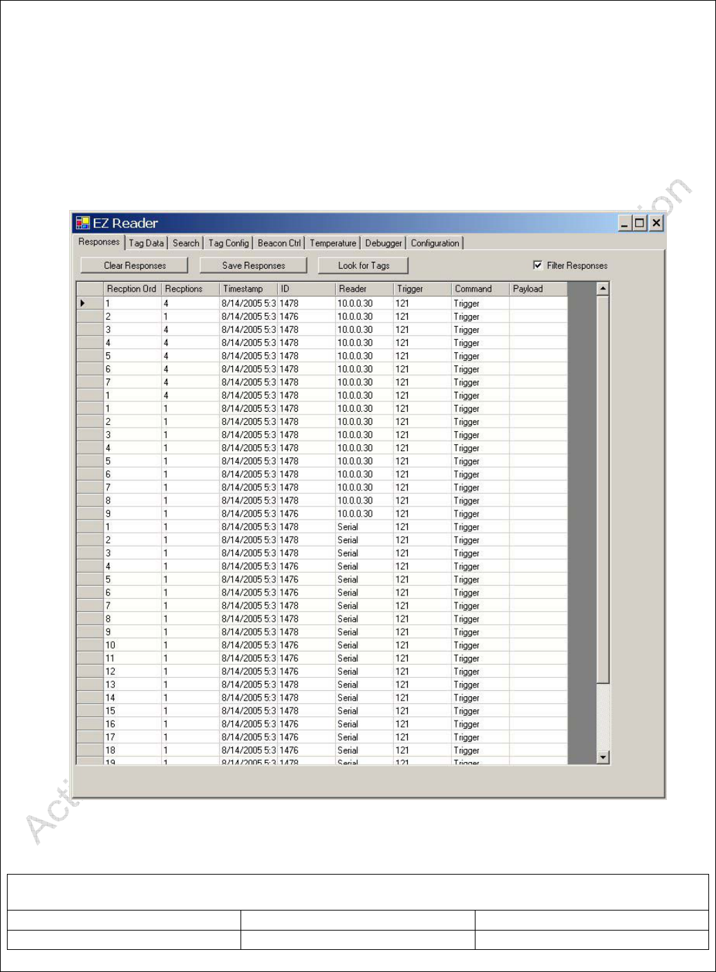
4.3.1. Responses Screen
The Responses Screen displays data received by the Reader or Trigger. Buttons, Data
Fields, and Settings are described below. Note that Tags can be triggered from other
Screens or from a Handheld Trigger. Data will be displayed on this screen any time it is
received by the Reader, regardless of the source of the Trigger.
Figure 8 - Responses Screen
Table 3 - Responses Screen
Clear Responses Button Clears Data Display
Save Responses Button Saves Data in a .csv

ARS - Active RFID Systems, Inc.
Active RFID Systems - Evaluation Kit Instruction Manual - Version 103105 Page 22 of 35
formatted file.
Look for Tags Button Sends a Trigger and Waits
for a Response. Trigger and
Response methods are
determined by the settings on
the Configuration Screen.
Filter Responses Setting/Check Box Filters duplicate responses
(i.e. more than one per Tag).
When this box is unchecked
every response is displayed.
Reception Order Data Field Numerical order of
responses.
Receptions Data Field Shows number of receptions
for each Tag. If Filter
Response is checked total
receptions is displayed.
Time Stamp Data Field Time and Date that data was
received.
ID Data Field Tag ID
Reader Data Field Displays how data was
received. Serial = Trigger.
IP Address = Reader.
Trigger Data Field ID of Trigger
Command Data Field Command Sent to Tags by
Trigger
Payload Data Field
ARS - Active RFID Systems, Inc.
Active RFID Systems - Evaluation Kit Instruction Manual - Version 103105 Page 23 of 35
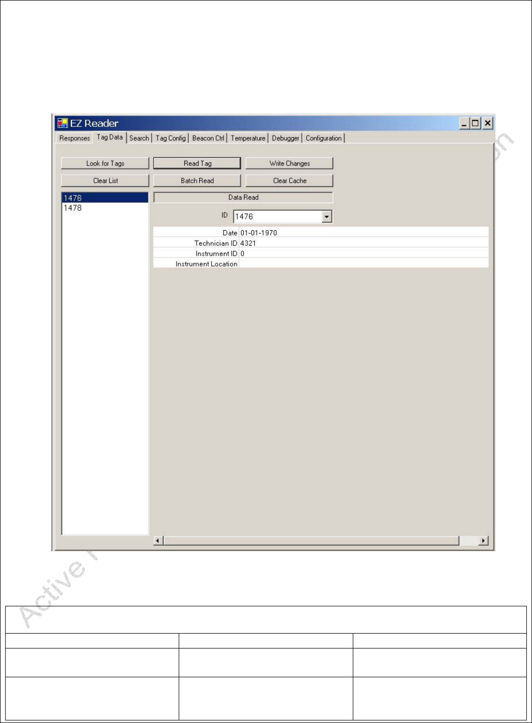
4.3.2. Tag Data Screen
The Tag Data Screen displays data entries as defined in the Tag Memory Map.
Figure 9 - Tag Data Screen
Table 4 - Tag Data Screen
Clear Responses Button Clears Data Display
Save Responses Button Saves Data in a .csv
formatted file.
Look for Tags Button Sends a Trigger and Waits
for a Response. Trigger and
Response methods are

ARS - Active RFID Systems, Inc.
Active RFID Systems - Evaluation Kit Instruction Manual - Version 103105 Page 24 of 35
determined by the settings on
the Configuration Screen.
Filter Responses Setting/Check Box Filters duplicate responses
(i.e. more than one per Tag).
When this box is unchecked
every response is displayed.
Reception Order Data Field Numerical order of
responses.
Receptions Data Field Shows number of receptions
for each Tag. If Filter
Response is checked total
receptions is displayed.
Time Stamp Data Field Time and Date that data was
received.
ID Data Field Tag ID
Reader Data Field Displays how data was
received. Serial = Trigger.
IP Address = Reader.
Trigger Data Field ID of Trigger
Command Data Field Command Sent to Tags by
Trigger
Payload Data Field
ARS - Active RFID Systems, Inc.
Active RFID Systems - Evaluation Kit Instruction Manual - Version 103105 Page 25 of 35
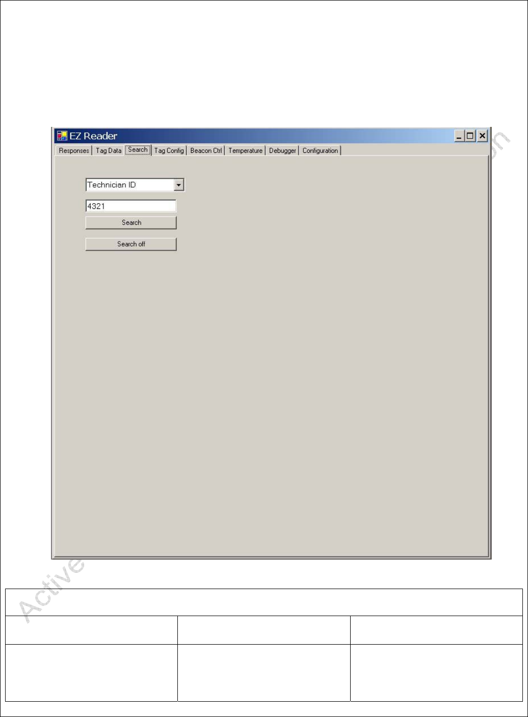
4.3.3. Search Screen
The Search Screen can be used to search for specific data stored in a Tag or group of
Tags,
Table 5 - Search Screen
Pull Down Menu Lists Data Fields from
Memory Map
Data Field Alphanumeric Data Entry
Field. Data to be searched
for in Tag Memory entered
here.

ARS - Active RFID Systems, Inc.
Active RFID Systems - Evaluation Kit Instruction Manual - Version 103105 Page 26 of 35
Search Button Initiates Search Command
Search Off Button Ends Search
ARS - Active RFID Systems, Inc.
Active RFID Systems - Evaluation Kit Instruction Manual - Version 103105 Page 27 of 35
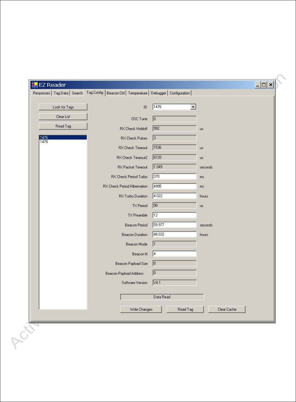
4.3.4. Tag Configuration Screen
The Tag Configuration Screen displays Tag Configuration data, i.e. settings stored in the
Tag. Tag Configuration data should not be modified.
ARS - Active RFID Systems, Inc.
Active RFID Systems - Evaluation Kit Instruction Manual - Version 103105 Page 28 of 35
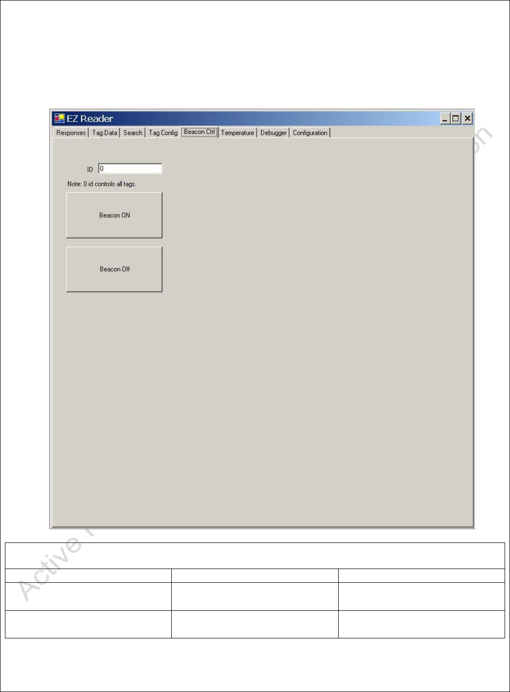
4.3.5. Beacon Ctrl Screen
The Beacon Control Screen can be used to turn the Tag(s) Beacon Mode on and Off.
Table 6 - Beacon Control Screen
ID Data Entry Field Enter ID of Tag in this field.
Beacon ON Button Initiates Beacon Mode in Tag
(or Tags)
Beacon Off Button Turns off Beacon Mode in
Tag (or Tags)
ARS - Active RFID Systems, Inc.
Active RFID Systems - Evaluation Kit Instruction Manual - Version 103105 Page 29 of 35
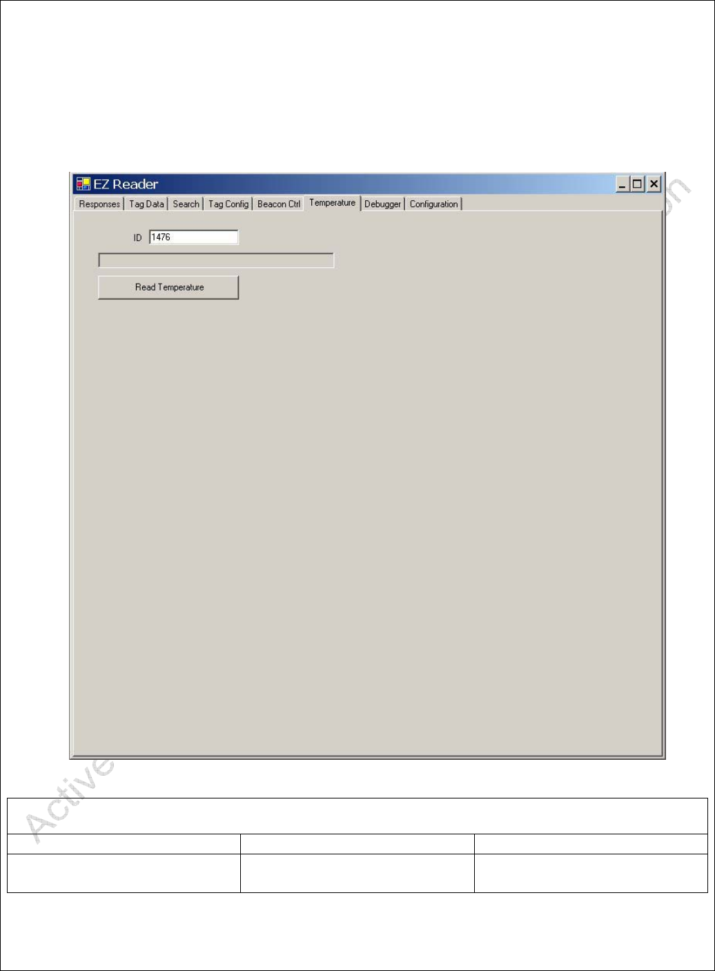
4.3.6. Temperature Screen
The Temperature Screen is used to read and display the temperature measured by a Tag.
Note that not all Tags are temperature enabled.
Table 7 - Temperature Screen
ID Data Entry Field Enter ID of Tag in this field.
Read Temperature Button Initiates Reading of Tag
Temperature
ARS - Active RFID Systems, Inc.
Active RFID Systems - Evaluation Kit Instruction Manual - Version 103105 Page 30 of 35
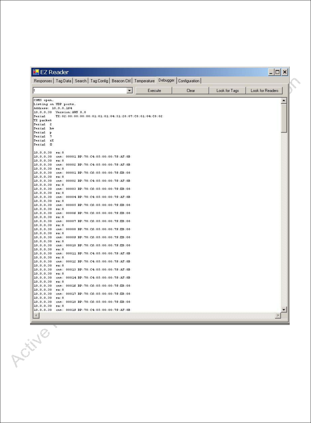
4.3.7. Debugger Screen
Functionality reserved for future use or Technical Support.
Figure 10 - Debugger Screen

ARS - Active RFID Systems, Inc.
Active RFID Systems - Evaluation Kit Instruction Manual - Version 103105 Page 31 of 35
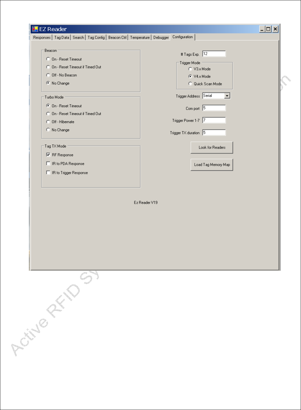
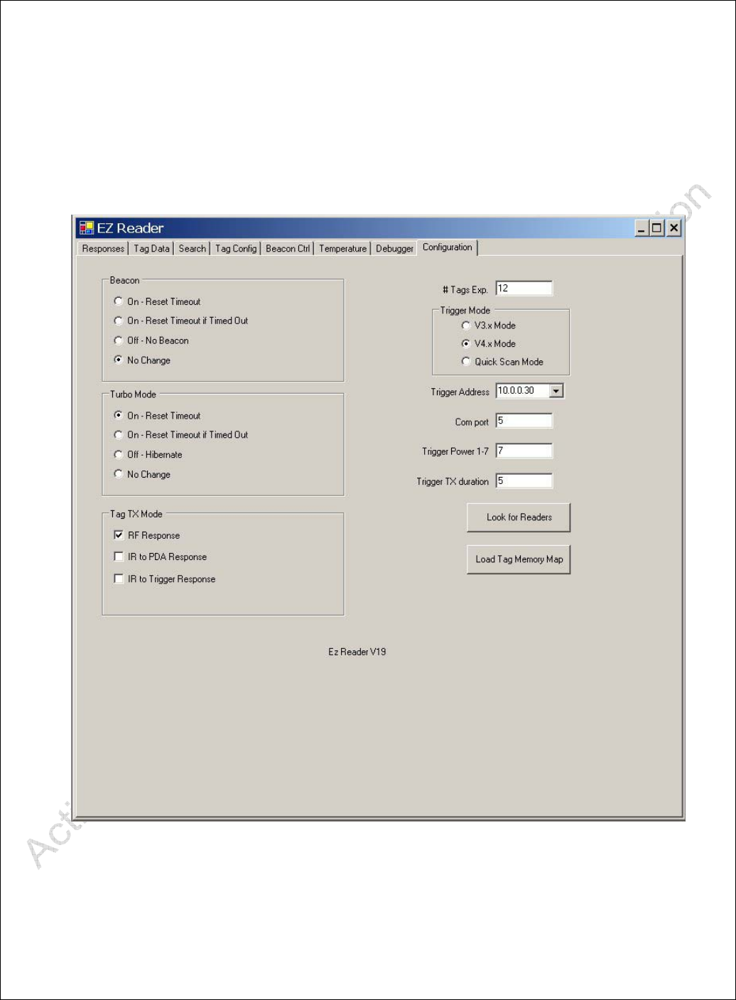
4.3.8. Configuration Screen
The EZ Reader Configuration Screen contains settings used to control Tag and System
(i.e. Reader and Trigger) behavior.
Figure 11 - Configuration Screen
Table 8 - Configuration Screen
Tag TX Mode Check Box Select Modes related to
Tag response to a Trigger.
# Tags Exp Numeric Field Sets the number of Tags
expected to respond to a

ARS - Active RFID Systems, Inc.
Active RFID Systems - Evaluation Kit Instruction Manual - Version 103105 Page 32 of 35
Trigger. Used for anti-
collision algorithm.
Trigger Mode Radio Button Selects Trigger Software
Version
Trigger Address Pull Down Menu Selects Trigger as on of
the following:
Serial = Easy-Trak Trigger
IP Address = Easy-Trak
Reader
Com Port Numeric Field Sets Communications
(Serial) Port connected to
Easy-Trak Reader
Trigger Power Numeric Field Sets IR Power Level of
Trigger
Trigger TX Duration Numeric Field Sets length of Trigger in
Seconds
Look For Readers Button Initiates search on serial
Ports for Easy-Trak
Triggers
Load Tag Memory Map Button Opens File Dialog box to
allow Tag Memory Map
file to be loaded into EZ
Reader software
ARS - Active RFID Systems, Inc.
Active RFID Systems - Evaluation Kit Instruction Manual - Version 103105 Page 33 of 35
A.1 Installing the USB/Serial Cable Adapter and Driver
(Optional)
The Easy-Trak Trigger connects to the PC via the custom serial cable. If the PC does
not have a serial port the USB/Serial Cable Adapter must be used. The required drivers
are supplied on the CD. The following procedure should be used to install the driver on
the PC.
Connect the supplied Serial Cable to the USB/Serial Adapter.
Plug the USB/Serial Adapter into any USB port on the PC.
NOTE! The USB/Serial Adapter should be plugged into the SAME USB PORT every
time. Otherwise the PC will automatically select a different serial port number and the
settings in the EZ Reader software will have to be changed.
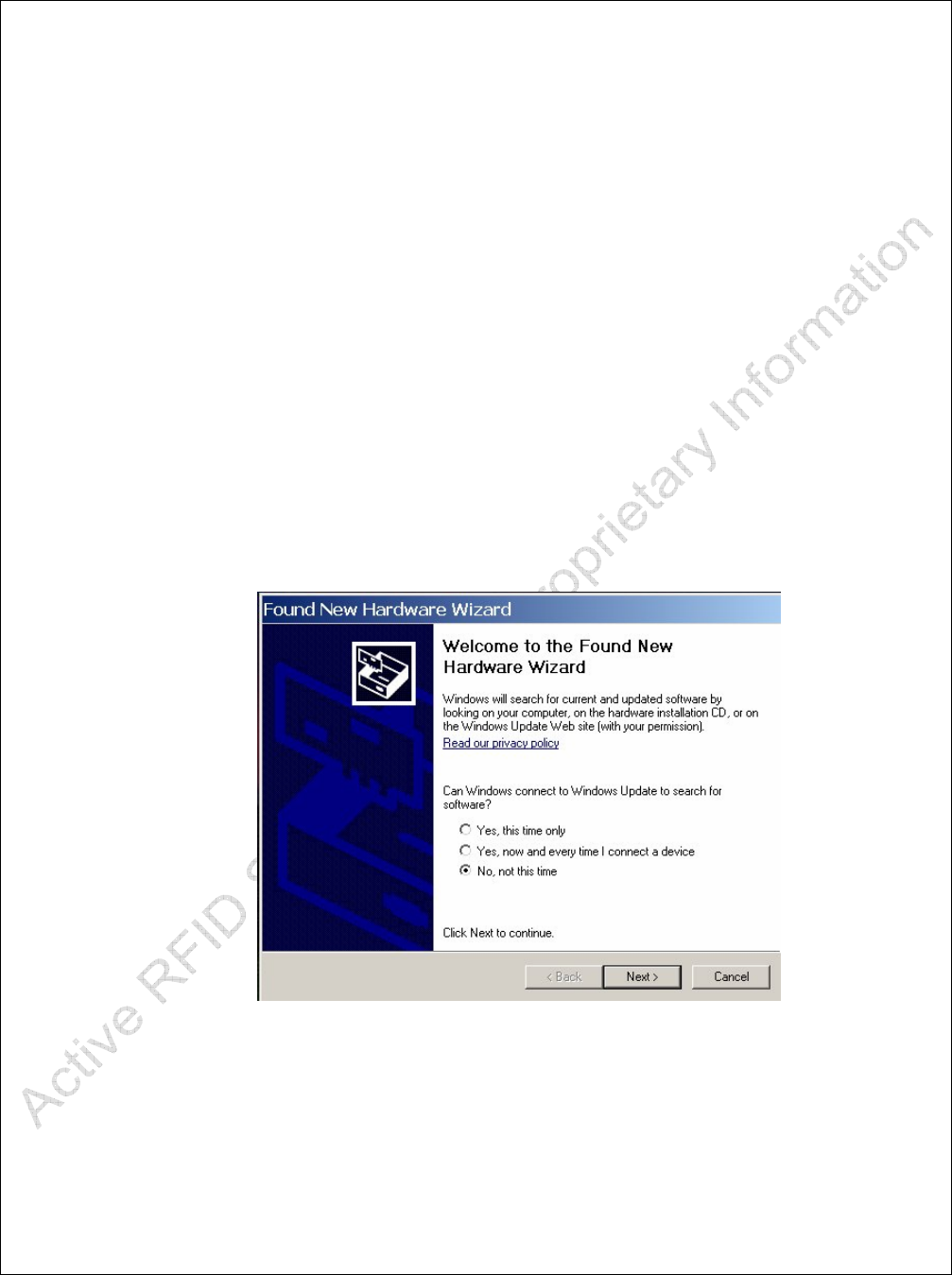
Windows should recognize that new hardware has been connected to the PC and the
'Found New Hardware Wizard' dialog box should open. See Figure A1.
Figure A1
Select 'No, not this time' and click 'Next'. The Dialog box shown in Figure A2 should
appear.
ARS - Active RFID Systems, Inc.
Active RFID Systems - Evaluation Kit Instruction Manual - Version 103105 Page 34 of 35
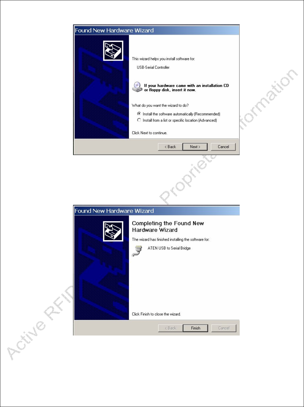
Figure A2
Be sure the supplied CD is in the PC and click 'Install the software automatically'. Click
Next. The Dialog box shown in Figure A3 should appear.
Figure A3
The driver should be loaded from the CD and installed on the PC. The balloon shown in
Figure A4 should be displayed. Driver installation is complete.

ARS - Active RFID Systems, Inc.
Active RFID Systems - Evaluation Kit Instruction Manual - Version 103105 Page 35 of 35
Figure A4