Ademco 8DL6OCC1 Wireless Occupancy Sensor User Manual 20190313 v1 SiXOCC EXHIBIT 7 2 Install Guide

Ademco Inc. Wireless Occupancy Sensor 20190313 v1 SiXOCC EXHIBIT 7 2 Install Guide

Contents

User Manual_20190313_v1 - SiXOCC EXHIBIT 7-2 Install Guide
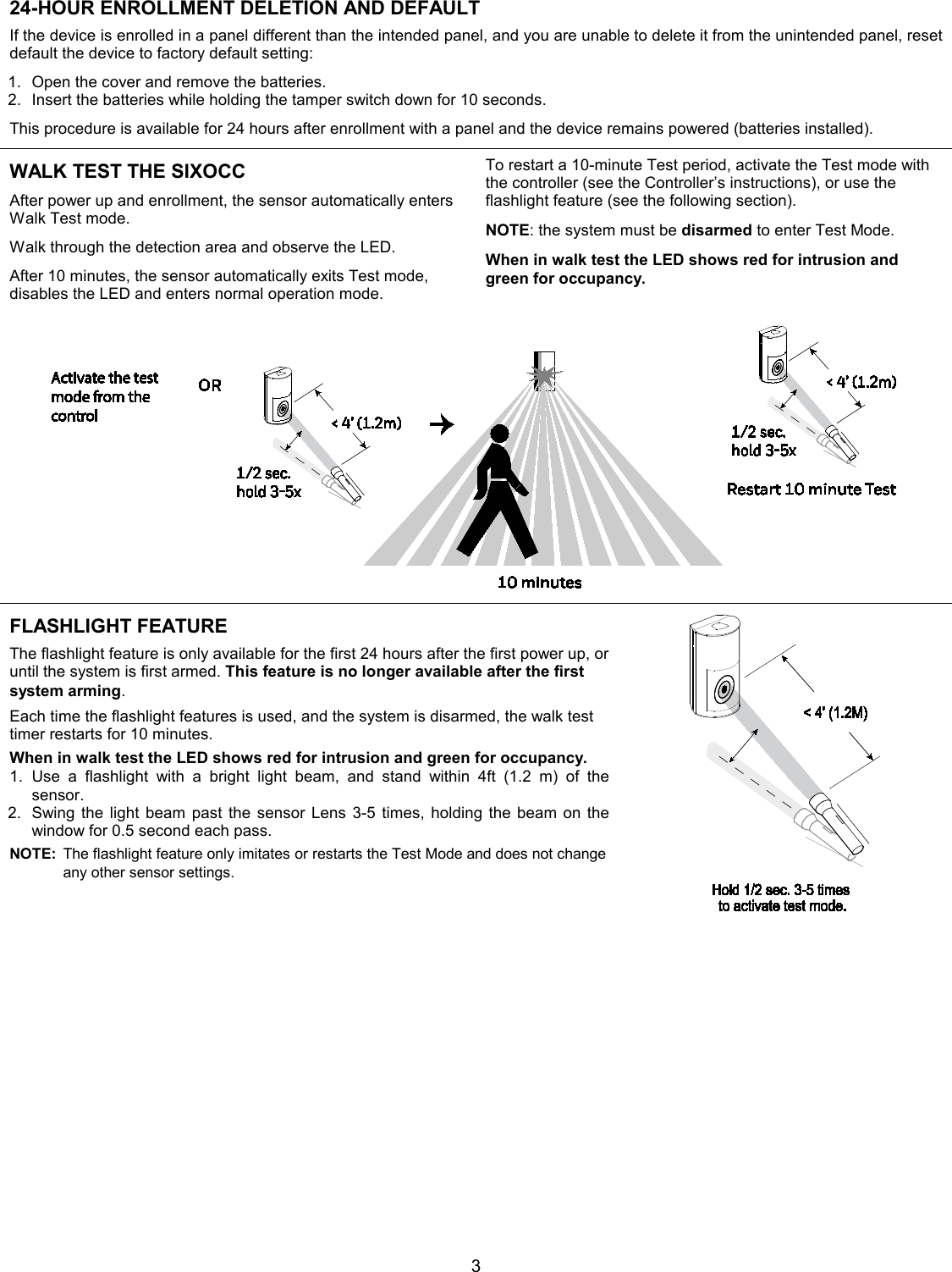
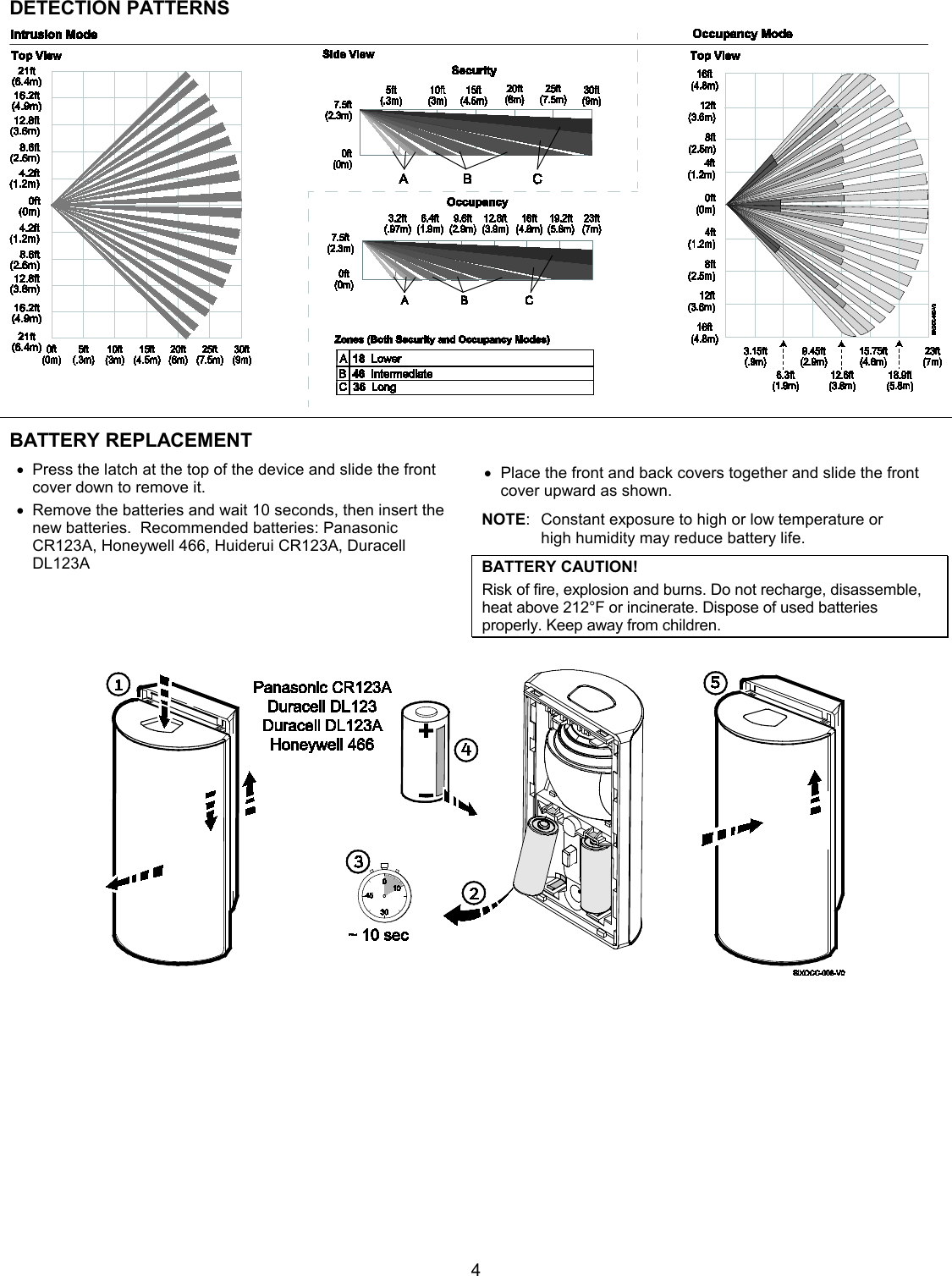
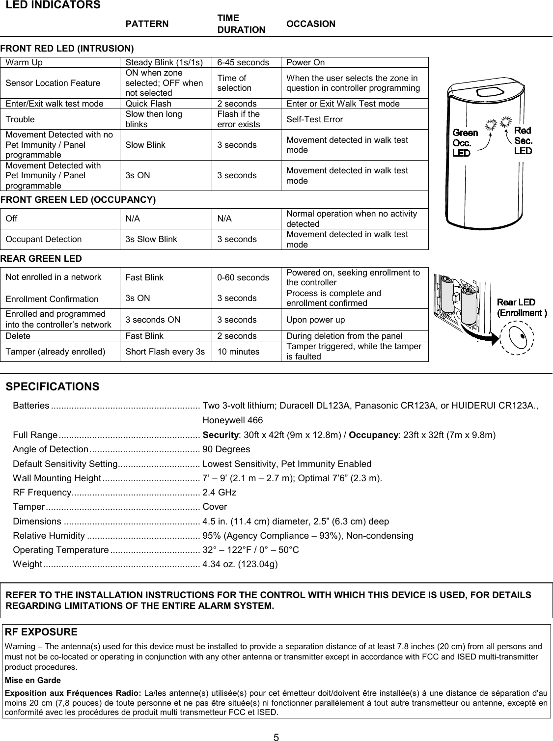
 1 SiXOCC Wireless Occupancy Sensor INSTALLATION INSTRUCTIONS The Honeywell Home SiXOCC Occupancy Sensor is a wireless device used with controllers that support Honeywell Home’s SiX™ series devices.   The SiXOCC combines security motion detection and automation in one unit.  Using automation, or occupancy mode allows the device to signal the control to turn a light on or off and/or a thermostat to a pre-programmed temperature. NOTE: Lights controlled via Z-Wave devices have not been evaluated by ETL. SECURITY SENSOR The security sensor reacts to movement and tells the panel to react based on the control’s programming.   1. Typically, it’s programmed as an interior follower. 2. LED walk test mode indication, one for the intrusion detection and the other for the occupancy detection. (See testing for more information.)  3. Up to 40 pounds’ pet immunity.  If the system is Armed, the control goes into alarm.  If the system is disarmed it turns the light on (or adjusts the thermostat) based on the explanation below. MOUNTING LOCATION • The optimal range is obtained at a mounting height of 7’ 6” (2.3m).   • Allow a clear line-of-sight to all areas to protect. • Do not directly face windows. • Avoid close-proximity to moving machinery, fluorescent lights, and heating/cooling sources. For use in applications with pets up to 40 pounds (36 kilograms). In Applications with Animals: • Mount with the center of the device at 7.5 feet (2.3m) • Mount where pet cannot come within 6 feet (1.8m) of the sensor by climbing on furniture, stairs, boxes or other objects. Test each installation to determine exact level of animal immunity; levels vary based on environmental differences and the amount of heat radiated by an animal. OCCUPANCY SENSOR When the control is disarmed (deactivated), the occupancy sensor switches to occupancy mode and reacts to the user’s programming in the control.  Logic is as follows: General Operation 1. First detection activates turns on the lights and/or adjusts the temperature. Any small movement, such as the turning a page of a book or swiping a tablet will continue to keep the light on and temperature at the programmed levels. 2. When it stops detecting movement for a pre-defined time-period defined by the user/ installer, it will turn off the light and increase or lower the temperature until movement is detected again.  Daylight Savings  Daylight Savings sensor detects the lighting level in the room. 1. Turns on lights only if the daylight is below a certain level and tries to keep the same amount of light in the room. 2. Once the daylight has been evaluated, the SiXOCC decides when to turn on the light.  Depending on the level the light turns on to 25%, 50%, 75%, and 100%. Example: If the natural room light level is at 100%, then the light does not turn on; at 0% natural light, the light turns on to 100%. 3. The level the light turns on can be set to a certain % (vs. slowly increasing the light level).  For example, any natural light level decrease turns on the light to 100%. Programmable to turn the feature on (described above), or off (when it detects any movement).
 2 MOUNTING OPTIONS  After enrolling, verify adequate signal strength by conducting Go/No Go tests (see the controller’s instructions) with the device in its intended mounting location. Adjust the device location and orientation as necessary. The SIXOCC can be mounted on the wall or in corners: •  [A] = Wall mounting holes. •  [B] = Corner mounting holes. •  The rear tamper plate MUST be mounted to a stud, solid wood, or with a robust wall anchor.   ENROLL THE SIXOCC  NOTE:  Once enrolled in a system, the sensor cannot be  used with another controller until it is removed  from the current controller. See the Controller’s  instructions for details. Press down on the top latch and separate the front and back covers. 1. Put the controller in Programming Mode and when prompted: 2. Remove the battery tab to activate and begin the enrollment process. Or, if powered, press the tamper. 3. The green LED beneath the batteries flashes (up to about 20 seconds*) during enrollment. The device sends its unique MAC ID (Serial Number) and Services information to the controller. NOTE: Enrollment time varies depending on the signal  strength between the device and the controller. 4. Enrollment is confirmed when the LED is ON for 3 seconds. NOTE:  If the sensor is not successfully enrolled during  the enrollment period, the LED turns off and the  device enters a sleep mode. Activate a tamper or  remove and reinsert the batteries to restart the  enrollment process. NOTE:  Pet Immunity is selectable: Off or Up to   40 lbs (36 kg). Sensor Location Feature: To verify the location of each SiX device in an installation, enter programming mode and select a SiX device.  The device LED lights. Select it again to turn the LED off or select the next device to locate.   Signal Strength:  Range of 1-4 bars (green); should be minimum 1 green bar for the Zone being programmed. Four red bars indicate poor signal strength; the device should be relocated. See the Controller’s instructions for bar indication signal strength values.   Icon Description Signal Strength  Four Green Bars Good  Three Green Bars  Two Green Bars  One Green Bar  Four Red Bars  Relocate the device
 3 24-HOUR ENROLLMENT DELETION AND DEFAULT If the device is enrolled in a panel different than the intended panel, and you are unable to delete it from the unintended panel, reset default the device to factory default setting: 1. Open the cover and remove the batteries. 2. Insert the batteries while holding the tamper switch down for 10 seconds. This procedure is available for 24 hours after enrollment with a panel and the device remains powered (batteries installed). WALK TEST THE SIXOCC After power up and enrollment, the sensor automatically enters Walk Test mode. Walk through the detection area and observe the LED. After 10 minutes, the sensor automatically exits Test mode, disables the LED and enters normal operation mode. To restart a 10-minute Test period, activate the Test mode with the controller (see the Controller’s instructions), or use the flashlight feature (see the following section). NOTE: the system must be disarmed to enter Test Mode. When in walk test the LED shows red for intrusion and green for occupancy.  FLASHLIGHT FEATURE The flashlight feature is only available for the first 24 hours after the first power up, or until the system is first armed. This feature is no longer available after the first system arming. Each time the flashlight features is used, and the system is disarmed, the walk test timer restarts for 10 minutes. When in walk test the LED shows red for intrusion and green for occupancy. 1. Use a flashlight with a bright light beam, and stand within 4ft (1.2 m) of the sensor. 2. Swing the light beam past the sensor Lens 3-5 times, holding the beam on the window for 0.5 second each pass. NOTE: The flashlight feature only imitates or restarts the Test Mode and does not change any other sensor settings.
 4 DETECTION PATTERNS  BATTERY REPLACEMENT   • Press the latch at the top of the device and slide the front cover down to remove it.  • Remove the batteries and wait 10 seconds, then insert the new batteries.  Recommended batteries: Panasonic CR123A, Honeywell 466, Huiderui CR123A, Duracell DL123A  • Place the front and back covers together and slide the front cover upward as shown. NOTE:  Constant exposure to high or low temperature or  high humidity may reduce battery life. BATTERY CAUTION! Risk of fire, explosion and burns. Do not recharge, disassemble, heat above 212°F or incinerate. Dispose of used batteries properly. Keep away from children.
 5  LED INDICATORS      PATTERN TIME DURATION OCCASION  FRONT RED LED (INTRUSION)    Warm Up Steady Blink (1s/1s) 6-45 seconds Power On  Sensor Location Feature ON when zone selected; OFF when not selected Time of selection When the user selects the zone in question in controller programming Enter/Exit walk test mode Quick Flash 2 seconds Enter or Exit Walk Test mode Trouble Slow then long blinks Flash if the error exists Self-Test Error Movement Detected with no Pet Immunity / Panel programmable Slow Blink 3 seconds Movement detected in walk test mode Movement Detected with Pet Immunity / Panel programmable 3s ON 3 seconds Movement detected in walk test mode FRONT GREEN LED (OCCUPANCY)     Off N/A N/A Normal operation when no activity detected Occupant Detection  3s Slow Blink 3 seconds Movement detected in walk test mode REAR GREEN LED     Not enrolled in a network Fast Blink  0-60 seconds Powered on, seeking enrollment to the controller  Enrollment Confirmation 3s ON 3 seconds Process is complete and enrollment confirmed Enrolled and programmed into the controller’s network 3 seconds ON 3 seconds Upon power up Delete Fast Blink 2 seconds During deletion from the panel Tamper (already enrolled) Short Flash every 3s 10 minutes Tamper triggered, while the tamper is faulted  SPECIFICATIONS Batteries .......................................................... Two 3-volt lithium; Duracell DL123A, Panasonic CR123A, or HUIDERUI CR123A.,  Honeywell 466 Full Range ....................................................... Security: 30ft x 42ft (9m x 12.8m) / Occupancy: 23ft x 32ft (7m x 9.8m) Angle of Detection ........................................... 90 Degrees Default Sensitivity Setting................................ Lowest Sensitivity, Pet Immunity Enabled Wall Mounting Height ...................................... 7’ – 9’ (2.1 m – 2.7 m); Optimal 7’6” (2.3 m).   RF Frequency.................................................. 2.4 GHz Tamper ............................................................ Cover Dimensions ..................................................... 4.5 in. (11.4 cm) diameter, 2.5” (6.3 cm) deep Relative Humidity ............................................ 95% (Agency Compliance – 93%), Non-condensing Operating Temperature ................................... 32° – 122°F / 0° – 50°C Weight ............................................................. 4.34 oz. (123.04g) REFER TO THE INSTALLATION INSTRUCTIONS FOR THE CONTROL WITH WHICH THIS DEVICE IS USED, FOR DETAILS REGARDING LIMITATIONS OF THE ENTIRE ALARM SYSTEM. RF EXPOSURE Warning – The antenna(s) used for this device must be installed to provide a separation distance of at least 7.8 inches (20 cm) from all persons and must not be co-located or operating in conjunction with any other antenna or transmitter except in accordance with FCC and ISED multi-transmitter product procedures. Mise en Garde Exposition aux Fréquences Radio: La/les antenne(s) utilisée(s) pour cet émetteur doit/doivent être installée(s) à une distance de séparation d'au moins 20 cm (7,8 pouces) de toute personne et ne pas être située(s) ni fonctionner parallèlement à tout autre transmetteur ou antenne, excepté en conformité avec les procédures de produit multi transmetteur FCC et ISED.
  FEDERAL COMMUNICATIONS COMMISSION (FCC) & INDUSTRY CANADA (IC) STATEMENTS The user shall not make any changes or modifications to the equipment unless authorized by the Installation Instructions or User's Manual. Unauthorized changes or modifications could void the user's authority to operate the equipment. CLASS B DIGITAL DEVICE STATEMENT This equipment has been tested to FCC requirements and has been found acceptable for use. The FCC requires the following statement for your information: This equipment generates and uses radio frequency energy and if not installed and used properly, that is, in strict accordance with the manufacturer's instructions, may cause interference to radio and television reception. It has been type tested and found to comply with the limits for a Class B computing device in accordance with the specifications in Part 15 of FCC Rules, which are designed to provide reasonable protection against such interference in a residential installation. However, there is no guarantee that interference will not occur in a particular installation. If this equipment does cause interference to radio or television reception, which can be determined by turning the equipment off and on, the user is encouraged to try to correct the interference by one or more of the following measures: •  If using an indoor antenna, replace it with a quality outdoor antenna. •  Reorient the receiving antenna until interference is reduced or eliminated. •  Move the radio or television receiver away from the receiver/control. •  Move the antenna leads away from any wire runs to the receiver/control. •  Plug the receiver/control into a different outlet so that it and the radio or television receiver are on different branch circuits. •  Consult the dealer or an experienced radio/TV technician for help. INDUSTRY CANADA CLASS B STATEMENT This Class B digital apparatus complies with Canadian ICES-003. Cet appareil numérique de la classe B est conforme à la norme NMB-003 du Canada. FCC / IC STATEMENT This device complies with Part 15 of the FCC Rules, and Industry Canada’s license-exempt RSSs. Operation is subject to the following two conditions: (1) This device may not cause harmful interference, and (2) This device must accept any interference received, including interference that may cause undesired operation. Cet appareil est conforme à la partie 15 des règles de la FCC et exempt de licence RSS d’Industrie Canada. Son fonctionnement est soumis aux conditions suivantes: (1) Cet appareil ne doit pas causer d’interférences nuisibles. (2) Cet appareil doit accepter toute interférence reçue y compris les interférences causant une réception indésirable.  Responsible Party / Issuer of Supplier’s Declaration of Conformity: Ademco Inc., a subsidiary of Resideo Technologies, Inc., 2 Corporate Center Drive., Melville, NY 11747, Ph: 516-577-2000 APPROVAL LISTINGS / APPROBATIONS HOMOLOGATIONS FCC / IC cETLus Listed    Conforms to UL 639   Certified to ULC-S306-03 OTHER STANDARDS SIA-PIR-01 RoHS   SUPPORT, WARRANTY, & PATENT INFORMATION For online support information, please go to: https://mywebtech.honeywellhome.com/  For the latest warranty information, go to: https://www.security.honeywellhome.com/hsc/resources/wa/index.html  For patent information, see https://www.resideo.com/patent   MyWebTech  Warranty  Patents   2 Corporate Center Drive, Suite 100 P.O. Box 9040, Melville, NY 11747  2018 Resideo Technologies, Inc.  www.resideo.com Ê800-23973cŠ 800-23973  2/18   Rev A The Honeywell Home Trademark is used under license from Honeywell International Inc.   All other trademarks are the properties of their respective owners. All rights reserved.

Navigation menu