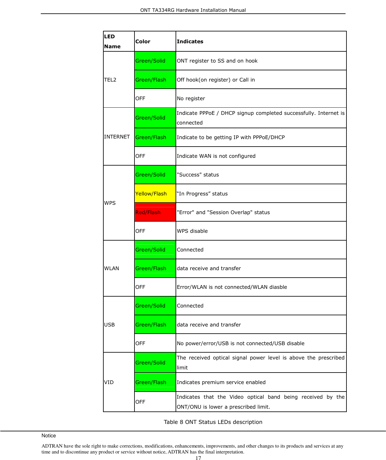
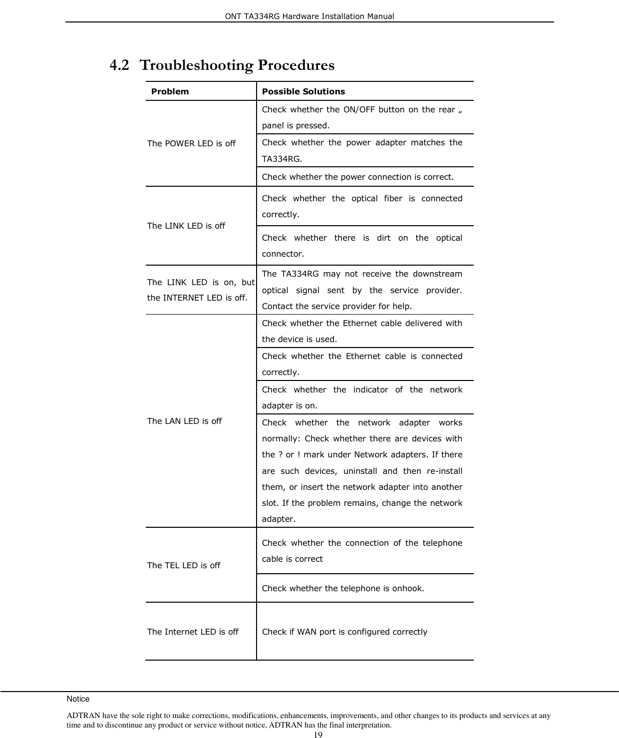
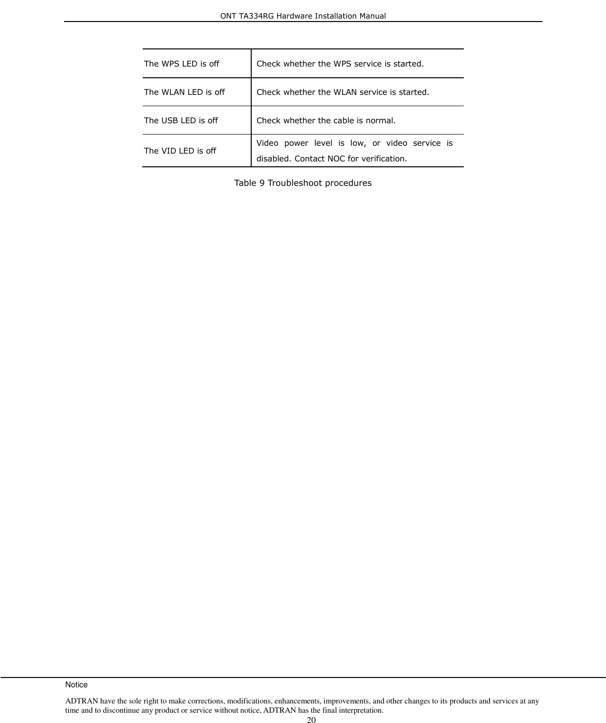
ADTRAN 1287567G1 TOTAL ACCESS 334RG User Manual

Adtran TOTAL ACCESS 334RG

User manual

                                                 ONT Hardware Installation Cambridge Industries Group Co. Ltd CAMBRIDGEIndust r ies (Gr o up) Co  Lt d.CAMBRIDGEIndust r ies (Gr o up) Co  Lt d.ONT TA334RG Hardware Installation Manual Aug. 2012 Rev. 2 Indust r ies (Gr o up) Co  Lt d.CIGIndust r ies (Gr o up) Co  Lt d.CIG
ONT TA334RG Hardware Installation Manual Rev. 1: Oct. 2011  Cambridge Industries Group Co. Ltd II Table of  Contents  About This Document  _________________________________________________________ IV Purpose ___________________________________________________________________________ IV Intended Audience  _________________________________________________________________ IV Chapter Overview  __________________________________________________________________ IV 1. Product Description _________________________________________________________  1 1.1 Introduction __________________________________________________________________ 1 1.2 Services ______________________________________________________________________ 1 1.3 Features ______________________________________________________________________ 1 1.4 Specifications _________________________________________________________________ 1 2. Safety _____________________________________________________________________  4 2.1 Basic Requirements ____________________________________________________________ 4 2.2 Environmental Requirements ____________________________________________________ 5 2.3 Electrical Safety _______________________________________________________________ 5 2.4 Laser Safety ___________________________________________________________________ 6 2.5 Instructions for Cleaning ________________________________________________________ 6 2.6 Other Instructions _____________________________________________________________ 6 2.7 Instructions for Environment Protection ___________________________________________ 6 3. Installation  ________________________________________________________________  7 3.1 Site Preparation  _______________________________________________________________ 7 3.1.1 Environmental Requirements __________________________________________________________ 7 3.1.2 Power Requirements  _________________________________________________________________ 7 3.2 Get to Know the ONT __________________________________________________________ 7 3.3 Mountings & Connecting to Network _____________________________________________ 8 3.3.1 Installing the ONT on Wall ____________________________________________________________ 8 3.3.2 Installing the ONT on Desktop  _______________________________________________________ 10 3.3.3 Uninstalling the ONT  _______________________________________________________________ 10 3.4 Connecting Power  ____________________________________________________________  11 3.5 Connecting Telephone (POTS) Service ___________________________________________  11 3.6 Connecting Ethernet Service ____________________________________________________  11 3.7 Connecting Analog Video Service ________________________________________________ 12 3.8 Verifying the Installation _______________________________________________________ 13 3.8.1 Activating the ONT _________________________________________________________________ 13 3.8.2 Verifying Services ___________________________________________________________________ 14 4. Troubleshooting ___________________________________________________________  15
ONT TA334RG Hardware Installation Manual Rev. 1: Oct. 2011  Cambridge Industries Group Co. Ltd III 4.1 ONT Status LEDs ____________________________________________________________ 15 4.2 Troubleshooting Procedures ____________________________________________________ 19
ONT TA334RG Hardware Installation Manual Rev.1: Oct. 2011  Cambridge Industries Group Co. Ltd IV About This Document   Purpose  This  guide  describes  how  to  install  the  ADTRAN  optical  network  termination  unit  (ONT)  at  the customer premises.  Intended Audience  This document is intended for technicians responsible for:  Unpacking and mounting the ONT and power supply  Connecting the ONT to the PON network  Connecting services to the ONT  Chapter Overview  This manual is organized as follows:  Chapter 1: Product Description Provides  an  introduction  to  the  ONT  including  physical,  electrical,  environmental  and  optical specifications. Compliance information is also provided. Chapter 2: Safety Provides  electrical,  electrostatic,  and  laser  safety  information;  fiber  optic  cable  handling techniques are also discussed. Chapter 3: Installing the ONT Describes installation  procedures including site  preparation,  unpacking  and  mounting  the  ONT, connecting power and fiber optic and cables, connecting service cables, activating the ONT, and verifying the installation. Chapter 4: Troubleshooting Explains ONT LED behavior and provides basic troubleshooting guidelines.
ONT TA334RG Hardware Installation Manual Notice ADTRAN have the sole right to make corrections, modifications, enhancements, improvements, and other changes to its products and services at any time and to discontinue any product or service without notice, ADTRAN has the final interpretation.    1 1. Product Description   1.1 Introduction  Optical  Network  Terminal  (ONT)  model  TA334RG  is  an  ITU-T  G.984  compliant  device  that receives  voice, data,  and  video  traffic in  the  form  of  optical signal  from  the  service provider’s passive optical network (PON) and transmitted it to the desired format at residential or business premises. Upstream traffic  is  likewise  transmitted  to  the  PON  network  via  the  fiber  optic  cable.  A  single optical fiber carries both upstream and downstream traffic.  1.2 Services  ONT TA334RG is equipped with ITU-T G.984 compliant 2.5G Downstream and 1.25G Upstream GPON UPLINK interface, and the following service ports1:  Four  10/100/1000  Base-T  Ethernet  ports  for  high  speed  internet  access  and  IPTV/VOD services  Two POTS (VoIP) service ports for voice services  Integrated 802.11b/g/n wireless  One USB Host ports for file-sharing service    One Analog Video service port for video broadcast services ONT TA334RG has built-in capability for  remote management like supervision, monitoring, and maintenance.  1.3 Features  The ONT incorporates the following features:  Single  fiber  GPON  interface  with  1244Mbit/s  upstream  and  2488Mbit/s  downstream  data rates  Advanced data features such as VLAN tag manipulation, classification, and filtering.  Traffic classification and QoS capability  3 REN per line  Multiple voice Codec  Optional Remote Bandwidth Control function: Premium Service and Basic Service for Video Overlay  Rich set of LED indications for alarming and maintenance  1.4 Specifications                                                        1  Some customized models may only provide a subset of service interfaces mentioned in this manual, for example, only four 10/100/1000 Base-T Ethernet ports are provided.
ONT TA334RG Hardware Installation Manual Notice ADTRAN have the sole right to make corrections, modifications, enhancements, improvements, and other changes to its products and services at any time and to discontinue any product or service without notice, ADTRAN has the final interpretation.    2  ONT  physical,  electrical,  optical,  and  environmental  specifications  and  compliance  information are listed in the following tables.  Dimensions  229mm (width) by 174mm (depth) by 41mm (height)(without bracket) 229mm (width) by 174mm (depth) by 49mm (height)(with bracket) Weight  0.7 KG excluding power adaptor GPON interface  SC/APC angled optical connector POTS interface  RJ-11 connector Ethernet interface  RJ-45 connector Table 1 Physical specification  Input Power  +12V DC power input Power Supply  AC power supply with included power adapter Power Consumption  < 13.34W Table 2 Electrical specification   Temperature  0 ~ 40° C Humidity  5 ~ 95% relative humidity Table 3 Environmental specification
ONT TA334RG Hardware Installation Manual Notice ADTRAN have the sole right to make corrections, modifications, enhancements, improvements, and other changes to its products and services at any time and to discontinue any product or service without notice, ADTRAN has the final interpretation.    3 PON  ITU-T G.984.1, G.984.2, G.984.2 amd1, G.984.3, G.984.4, G.983.2 EMC  ETSI EN 300386, EN 55022 (Class B) Safety EN 60950 Laser  ITU-T Rec.G.984.2 (Class B+), G983.3  FCC 47 CFR Part 15, Class B  FDA 21 CFR 1040.10 and 1040.11, Class I  IEC 60825, Class I Table 4 Compliance    Minimum  Nominal  Maximum  Notes Transmitter Wavelength  1260 nm  1310 nm  1360 nm   Transmit power  0.5 dBm    +5 dBm   Digital receiver Wavelength  1480 nm  1490 nm  1500 nm   Sensitivity  -27 dBm     Minimum  received  power for BER<10-10 Overload      -8 dBm Maximum  received  power for BER<10-10 Table 5 Optical specification
ONT TA334RG Hardware Installation Manual Notice ADTRAN have the sole right to make corrections, modifications, enhancements, improvements, and other changes to its products and services at any time and to discontinue any product or service without notice, ADTRAN has the final interpretation.    4 2. Safety This device complies with Part 15 of the FCC Rules / Industry Canada licence-exempt  RSS standard(s). Operation is subject to the following two conditions: (1) this device   may not cause harmful interference, and (2) this device must accept any interference   received, including interference that may cause undesired operation. Le  présent  appareil  est  conforme  aux  CNR  d'Industrie  Canada  applicables  aux  appareils radio  exempts de  licence.  L'exploitation  est  autorisée aux deux  conditions  suivantes :  (1) l'appareil  ne  doit  pas  produire  de brouillage, et  (2) l'utilisateur  de l'appareil doit  accepter tout  brouillage  radioélectrique  subi,  même  si  le  brouillage  est  susceptible  d'en compromettre le fonctionnement. Changes  or  modifications  not expressly  approved by the  party responsible  for  compliance could void the user's authority to operate the equipment. This  equipment has  been tested  and  found  to  comply with the  limits  for  a  Class B  digital device,  pursuant  to  part  15  of  the  FCC  Rules.  These  limits  are  designed  to  provide reasonable  protection  against  harmful  interference  in  a  residential  installation.  This equipment generates uses and can radiate radio frequency energy and, if not installed and used  in  accordance  with  the  instructions,  may  cause  harmful  interference  to  radio communications.  However,  there  is  no  guarantee  that  interference  will  not  occur  in  a particular  installation.  If  this  equipment  does  cause  harmful  interference  to  radio  or television  reception,  which  can  be  determined  by  turning  the  equipment  off  and  on,  the user is encouraged to try to correct the interference by one or more of the following  measures: —Reorient or relocate the receiving antenna. —Increase the separation between the equipment and receiver. —Connect the equipment into an outlet on a circuit different from that to which the receiver is connected. —Consult the dealer or an experienced radio/TV technician for help. MPE Requirements To  satisfy  FCC  /  IC  RF  exposure  requirements,  a  separation  distance  of  20  cm  or  more should  be  maintained  between  the  antenna  of  this  device  and  persons  during  device operation.To  ensure  compliance,  operations  at  closer  than  this  distance  is  not recommended.  Les  antennes  installées  doivent  être  situées  de  facon  à  ce  que  la  population  ne  puisse  y être exposée à une distance de moin de 20 cm. Installer les antennes de facon à ce que le personnel ne  puisse approcher  à 20  cm  ou moins de  la position  centrale de l’  antenne.La FCC des éltats-unis stipule que cet appareil doit être en tout temps éloigné d’au moins 20 cm des personnes pendant son functionnement. Region Selection Limited by local law regulations, version for North America does not have region selection option.   2.1 Basic Requirements  Install the device in a well-ventilated place that is not directly exposed to sunlight.  Keep  the  device  dry  and  prevent  the  device  from  coming  into  contact  with  other  objects during storage, transportation, and operation of the device.
ONT TA334RG Hardware Installation Manual Notice ADTRAN have the sole right to make corrections, modifications, enhancements, improvements, and other changes to its products and services at any time and to discontinue any product or service without notice, ADTRAN has the final interpretation.    5  Install the device in compliance with the requirements.  Do not  open the  device  enclosures without permission, but  contact  the  service technician when a problem occurs with the device.  No entity or person should modify the structure, security design, performance design, etc. of the device without authorization.  Abide by  local  laws and regulations and respect the  legal rights  of others  when using  the device.  2.2 Environmental Requirements  Install the device in a well-ventilated place that is not directly exposed to sunlight.  Keep the device clean.  Keep the device away from water sources or wet places.  Do not place any objects on top of the device. This is to protect the device from damage, such as overheating or melting, which can be caused by those objects.  Leave a space of at least 50mm around the device for heat dissipation.  Leave a space of at least 100mm on the top of the device for heat dissipation.  Keep  the  device  away  from  heat  sources  or  fire  sources,  such  as  electric  heaters  and candles.  Keep  the  device  away  from  electrical  appliances  with  strong  magnetic  fields  or  strong electric fields, such as microwave ovens, refrigerators, and mobile phones.  Do not store the device in an environment where there are corrosive chemicals.  2.3 Electrical Safety  Use the accessories delivered with the device, such as the power adapter, battery, etc..  The  power  supply  voltage  and  current  of  the  device  must  meet  the  requirements  on  the input voltage and current of the device, and provide current overload protection.  Do not connect the POTS port to an external PSTN line, to prevent damage to the device or cause other safety issues.    Keep the power plug clean and dry to avoid electric shock or other hazards.  Follow the insulation requirements of operational safety, for example, keep your hands dry, use insulated tools, etc., when plugging in the device’s cables.  Stop operation of the device and switch off the power before removing or inserting cables.  Switch off the power and remove all the cables from the device during periods of lightning activity, including the power cable, optical fibers, and network cables.   Switch off the power and remove the power plug if the device needs to be shut down for a long period of time.  Protect  the  device  from  water  or  other  liquids.  If  such  an  incident  occurs,  switch  off  the power immediately and remove all the  cables from the device, including the power cable, optical fibers, and network cables. Contact the  service technician in the event of  a device failure.  Do  not  step  on,  pull,  drag,  or  excessively  bend  the  cables  because  they  may  become damaged. Damaged cables can cause a device failure.  Do not use cables that are damaged or have deteriorated.
ONT TA334RG Hardware Installation Manual Notice ADTRAN have the sole right to make corrections, modifications, enhancements, improvements, and other changes to its products and services at any time and to discontinue any product or service without notice, ADTRAN has the final interpretation.    6  2.4 Laser Safety  Persons handling fiber optic cables must be trained for laser safety.  Do not bend the fiber optic cable to a diameter smaller than 7.5 cm/3 inches, so as not to damage the fiber or prevent the signal from passing through properly.  Do  not  look  directly  into  the optical  port  on  the  device  without  eye  protection.  The  laser emitted from the optical port can cause injury to your eyes.  2.5   Instructions for Cleaning  Before cleaning the device, stop operation of the device, switch off the power, and remove all  cables  from  the  device,  including  the  power  cable,  optical  fibers,  network  cables,  etc. When inserting and removing optical fibers, keep the optical fiber connectors clean.  When cleaning the device, do not use liquids such as cleaning fluid or spray-on detergents to clean the outer case of the device. Use a soft, dry cloth instead.  2.6 Other Instructions    In case of any abnormalities, such as smoke, abnormal sound, or odor, being emitted from the device, immediately stop operation of the device, switch off the power, and remove all cables,  from  the  device,  including  the  power  cable,  optical  fibers,  and  network  cables. Contact the service technician in the event of a device failure.  Prevent foreign objects such as metal objects from falling into the device through the heat dissipation mesh.  Protect the  outer  case of  the  device  from  scratches, as paint  that  peels  off  the  scratched areas can cause device abnormalities. If the paint falls into the device it may cause short circuits. In addition, peeled-off paint can cause an allergic reaction in the human body.  Ensure  that  the  device  is  kept  out  of  the  reach  of  children.  Guard  against  risks  such  as children playing with the device or swallowing small parts of the device.  2.7 Instructions for Environment Protection  Deposit the used devices and batteries at the specified recycling facility.  Abide by  local  laws  and regulations  when  handling  and disposing  of  packaging materials, dead batteries and used devices.  Disclaimer Please read and follow all safety instructions and warnings marked on the outside of the product and its  packaging, as  well  as  all  the  safety instructions  outlined in  this  manual  when  using  this  product. Once this product is installed and used, it is the responsibility of the user to know and understand how to safely use this product as described. The user shall bear the loss and/or any liability resulting from a  violation  of  the  safety  instructions.  The  equipment  manufacturers  are  not  liable  for  any  direct, indirect, incidental, special, consequential or punitive damages.
ONT TA334RG Hardware Installation Manual Notice ADTRAN have the sole right to make corrections, modifications, enhancements, improvements, and other changes to its products and services at any time and to discontinue any product or service without notice, ADTRAN has the final interpretation.    7 3. Installation   3.1 Site Preparation  3.1.1 Environmental Requirements  The ONT  will  operate  in  temperatures ranging  from 0°  C to  40°  C,  relatively humidity  ranging from 5% to 95%.  3.1.2 Power Requirements  The ONT  will  be shipped with  a universal power  adaptor.  However,  before installation, check  if the  AC  power  input  matches  the  specification  printed  on  the  power  adaptor  (input  voltage, current, etc.)  CAUTION:      Please use the power adaptor within the package only, or the replacement unit that  provided  by  ADTRAN.  Other  power  adaptor  may  cause  damage  to  the  ONT  and  other disasters.   3.2 Get to Know the ONT Look through the diagram below for getting an overview of several parts of the ONT.  POTS Interfaces Ethernet Interfaces Power Switch Button Power Interface Optical Interface WLAN Antenna USB InterfacesRF Interface UPS Power Interfaces
ONT TA334RG Hardware Installation Manual Notice ADTRAN have the sole right to make corrections, modifications, enhancements, improvements, and other changes to its products and services at any time and to discontinue any product or service without notice, ADTRAN has the final interpretation.    8  Figure 1 ONT Elements   3.3 Mountings & Connecting to Network  3.3.1 Installing the ONT on Wall  1. Locate a safe and accessible site for installation. 2. Align  the  ONT  mounting  bracket  on  the  wall.  There  are  two  mounting  directions,  either horizontal (Figure ) or vertical (Figure ). Make sure the install arrows is up when correctly mounted.  Figure 3 Bracket mounting: Horizontal direction Mounting Holes Mounting   Holes
ONT TA334RG Hardware Installation Manual Notice ADTRAN have the sole right to make corrections, modifications, enhancements, improvements, and other changes to its products and services at any time and to discontinue any product or service without notice, ADTRAN has the final interpretation.    9  Figure 4 Bracket mounting: Vertical direction  3. Mount  the  bracket  into  a  wall  stud  by  driving  the  two  sheet  metal  screws  into  the  wall through the bracket mounting holes (Figure ).
ONT TA334RG Hardware Installation Manual Notice ADTRAN have the sole right to make corrections, modifications, enhancements, improvements, and other changes to its products and services at any time and to discontinue any product or service without notice, ADTRAN has the final interpretation.    10  Figure 5 Mount the bracket into the wall  4. Wrap  the  fiber  optical  cable  on  the  fiber  storage  tray.  Make  sure  the  SC/APC  connector comes out from the bottom left side in case of horizontal mounting, or left up side in case of vertical mounting. Secure the fiber with the cable holder.  5. Slide the ONT unit into the mounting bracket in up to down direction, using the 4 guides on the  bracket.  Make  sure  the  panel  with  the  interfaces  is  facing  down  in  case  of  horizontal mounting, or facing left in case vertical mounting. 6. Remove  the  dust  covers  from  the  SC/APC  optical  connectors.  Clean  the  connector  if necessary. 7. Plug in the fiber connector to connect the ONT to the network.  3.3.2 Installing the ONT on Desktop  1. Locate a safe and accessible site for installation. 2. Place the ONT unit on the desk. 3. Remove  the  dust  covers  from  the  SC/APC  optical  connector.  Clean  the  connectors  if necessary. 4. Plug in the fiber connector to connect the ONT to the network.  3.3.3 Uninstalling the ONT  For uninstall the ONT on the wall: 1. Plug out the SC/APC optical connector. 2. If necessary, slide the ONT unit out of the mounting bracket in down to up direction.
ONT TA334RG Hardware Installation Manual Notice ADTRAN have the sole right to make corrections, modifications, enhancements, improvements, and other changes to its products and services at any time and to discontinue any product or service without notice, ADTRAN has the final interpretation.    11 3. If necessary, remove the optical fiber cables. 4. If necessary, remove the bracket mounting screws and then remove the mounting bracket.  For uninstall the ONT on the desktop: 1. Plug out the SC/APC optical connector. 2. If necessary, remove the optical fiber cables.   3.4 Connecting Power  1. Plug the circle two pin 12V DC power connector of power converter to ONT power port 2. Plug the input of power converter into a live AC outlet 3. Verify that the power (POWER) LED on the ONT is lit green indicating that local power is on and voltage is good.  3.5 Connecting Telephone (POTS) Service  1. Locate the premises’ telephone wire pair.   2. If the wire pair is not terminated, follow local practices to attach an RJ-11 connector.. 3. Plug the wire pair with RJ-11 connector into one of the ONT RJ-11 phone jacks. 4. Repeat step 2-3 as needed to connect additional phone lines.  Pin  Signal  Pin  Signal 1  Unused  3  Tip 2  Ring  4  Unused Table 6 POTS RJ-11 connector wiring pattern  DANGER:      Please  make  sure  the  wire  pair  connected  is  from/to  the  telephone.  Using  the wire pair from/to the PSTN network falsely may cause damage to user and the device.   3.6 Connecting Ethernet Service  1. Locate the premises’ Ethernet LAN cable.   2. If  the  cable  is  not  terminated,  follow  local  practices  to  attach  an  RJ-45  connector.  Table shows Ethernet RJ-45 connector wiring information. 3. Plug the Ethernet cable into the ONT RJ-45 Ethernet port. 4. Repeat step 2-3 as needed to connect additional Ethernet cables.
ONT TA334RG Hardware Installation Manual Notice ADTRAN have the sole right to make corrections, modifications, enhancements, improvements, and other changes to its products and services at any time and to discontinue any product or service without notice, ADTRAN has the final interpretation.    12 Pin  Color  Signal  Pin  Color  Signal 1  Orange/White  TX_D1+  5  Blue/White  BI_D3- 2  Orange  TX_D1-  6  Green  RX_D2- 3  Green/White  RX_D2+  7  Brown/White BI_D4+ 4  Blue  BI_D3+  8  Brown  BI_D4- Table 7 Ethernet RJ-45 connector wiring pattern  3.7 Connecting Analog Video Service  1. Locate the premises’ coax video cable. 2. If  the  cable  is  not  terminated,  follow  local  practices  to  attach  a  75  Ohm  type  F  coaxial connector. 3. Plug the video cable into the ONT Analog Video port.
ONT TA334RG Hardware Installation Manual Notice ADTRAN have the sole right to make corrections, modifications, enhancements, improvements, and other changes to its products and services at any time and to discontinue any product or service without notice, ADTRAN has the final interpretation.    13 3.8 Verifying the Installation  Check LED states to verify ONT status (Section 3.8.1). Services  are  not  available  until  the  ONT  is  ranged  and  provisioned  in  the  PON  network.  If services  must  be  verified  at  the  time  of  installation,  refer  to  Section  3.8.2  for  additional instructions.   3.8.1 Activating the ONT  Once  the  ONT  installation  is  complete,  follow  the  procedure  below  for  verifying  ONT  status. Figures below shows the typical status LED display after the ONT boot sequence is complete.  Figure 2 ONT has not yet been provisioned       Figure 3 ONT has already been provisioned  • Verify that the POWER LED light is green, indicating that local power level is good. • Verify that the LINK LED light is green, indicating that the ONT is operating normally. The  ONT  is  placed  into  service  remotely  through  the  OLT.  Services  to  the  ONT  are  likewise provisioned and turned up remotely through the PON network. - If  the  LINK  LED  lights  green,  indicating  that  the  ONT  is  communicating  with  the  PON network, no further activation is necessary and you can proceed to Section 3.8.2: Verifying Services. - If the LINK LED does not light green, contact the NOC (Network Operation Center) to activate the line. You may be required to provide or confirm the following information about the ONT: vendor, model number, serial number. Once the ONT has been activated in the network, and the LINK LED is lit green, you can proceed to Section 3.8.2: Verifying Services.
ONT TA334RG Hardware Installation Manual Notice ADTRAN have the sole right to make corrections, modifications, enhancements, improvements, and other changes to its products and services at any time and to discontinue any product or service without notice, ADTRAN has the final interpretation.    14 3.8.2 Verifying Services Follow  local  practices  to  connect  to  each  active  service  port  in  the  ONT  to  confirm  service activation. 1. If VID service is included in this installation, verify the VID LED is green. 2. Connect to each active phone jack to verify telephone numbers and services. Verify that the TEL LED lights green when a line is off hook. 3. If Ethernet  service  is  included in  this  installation, confirm that  data is  being  received and transmitted normally. The LAN LED will be flashed during data transmission. 4. If  WLAN  service  is  included  in  this  installation,  confirm  that  data  is  being  received  and transmitted on WLAN interface. Verify the WLAN LED is green when the WLAN is connected.
ONT TA334RG Hardware Installation Manual Notice ADTRAN have the sole right to make corrections, modifications, enhancements, improvements, and other changes to its products and services at any time and to discontinue any product or service without notice, ADTRAN has the final interpretation.    15 4. Troubleshooting   4.1 ONT Status LEDs  The  ONT  status  LEDs  located  on  the  enclosure  (Figure  4)  assist  with  installation  and maintenance procedures. These LEDs are described in detail in Table .  Figure 4 ONT Status LEDs location
ONT TA334RG Hardware Installation Manual Notice ADTRAN have the sole right to make corrections, modifications, enhancements, improvements, and other changes to its products and services at any time and to discontinue any product or service without notice, ADTRAN has the final interpretation.    16 LED Name Color  Indicates POWER Green/Solid  Normal. OFF  No power LINK   Green/Solid  Optical link is OK OFF  Optical link is NOT OK AUTH Green/Solid  ONU is authorized (O5) Green/Flash  ONU is registering (O2->O5) OFF  ONU is NOT authorized (O1 or O7) LAN1 OFF  Link down Green/Flash  Active(Tx and/or Rx) Green/Solid  Link up LAN2 OFF  Link down Green/Flash  Active(Tx and/or Rx) Green/Solid  Link up LAN3 OFF  Link down Green/Flash  Active(Tx and/or Rx) Green/Solid  Link up LAN4 OFF  Link down Green/Flash  Active(Tx and/or Rx) Green/Solid  Link up TEL1 Green/Solid  ONT register to SS and on hook Green/Flash  Off hook(on register) or Call in OFF  No register
ONT TA334RG Hardware Installation Manual Notice ADTRAN have the sole right to make corrections, modifications, enhancements, improvements, and other changes to its products and services at any time and to discontinue any product or service without notice, ADTRAN has the final interpretation.    17 LED Name Color  Indicates TEL2 Green/Solid  ONT register to SS and on hook Green/Flash  Off hook(on register) or Call in OFF  No register INTERNET Green/Solid Indicate PPPoE / DHCP signup completed successfully. Internet is connected Green/Flash  Indicate to be getting IP with PPPoE/DHCP OFF  Indicate WAN is not configured WPS Green/Solid  "Success" status Yellow/Flash  “In Progress” status Red/Flash  "Error" and "Session Overlap" status OFF  WPS disable WLAN Green/Solid  Connected Green/Flash  data receive and transfer OFF  Error/WLAN is not connected/WLAN diasble USB Green/Solid  Connected Green/Flash  data receive and transfer OFF  No power/error/USB is not connected/USB disable VID Green/Solid The  received  optical  signal  power  level  is  above  the  prescribed limit Green/Flash  Indicates premium service enabled OFF Indicates  that  the  Video  optical  band  being  received  by  the ONT/ONU is lower a prescribed limit. Table 8 ONT Status LEDs description
ONT TA334RG Hardware Installation Manual Notice ADTRAN have the sole right to make corrections, modifications, enhancements, improvements, and other changes to its products and services at any time and to discontinue any product or service without notice, ADTRAN has the final interpretation.    18
ONT TA334RG Hardware Installation Manual Notice ADTRAN have the sole right to make corrections, modifications, enhancements, improvements, and other changes to its products and services at any time and to discontinue any product or service without notice, ADTRAN has the final interpretation.    19 4.2 Troubleshooting Procedures Problem Possible Solutions The POWER LED is off Check whether the ON/OFF button on the rear „ panel is pressed. Check  whether  the  power  adapter  matches  the TA334RG. Check whether the power connection is correct. The LINK LED is off Check  whether  the  optical  fiber  is  connected correctly. Check  whether  there  is  dirt  on  the  optical connector. The  LINK  LED  is  on, but the INTERNET LED is off. The  TA334RG  may  not  receive  the  downstream optical  signal  sent  by  the  service  provider. Contact the service provider for help. The LAN LED is off Check whether the Ethernet cable delivered with the device is used. Check  whether  the  Ethernet  cable  is  connected correctly. Check  whether  the  indicator  of  the  network adapter is on. Check  whether  the  network  adapter  works normally:  Check  whether there are devices  with the ? or ! mark under Network adapters. If there are  such  devices,  uninstall  and  then  re-install them, or insert the network adapter into another slot. If the problem remains, change the network adapter. The TEL LED is off Check  whether  the  connection  of  the  telephone cable is correct Check whether the telephone is onhook. The Internet LED is off  Check if WAN port is configured correctly
ONT TA334RG Hardware Installation Manual Notice ADTRAN have the sole right to make corrections, modifications, enhancements, improvements, and other changes to its products and services at any time and to discontinue any product or service without notice, ADTRAN has the final interpretation.    20 The WPS LED is off  Check whether the WPS service is started. The WLAN LED is off  Check whether the WLAN service is started. The USB LED is off  Check whether the cable is normal. The VID LED is off Video  power  level  is  low,  or  video  service  is disabled. Contact NOC for verification. Table 9 Troubleshoot procedures

Navigation menu