ADTRAN TRC5045L1 Tracer 5045 Point-to-Point Spread Spectrum System User Manual 612805045L1 1A
Adtran Tracer 5045 Point-to-Point Spread Spectrum System 612805045L1 1A
UserManual.wiki
>
ADTRAN
>
TRC5045L1 User Manual
Manual
Navigation menu
Upload a User Manual
Namespaces
Wiki Guide
HTML
PDF
Info
Views
User Manual
Discussion / Help
Navigation
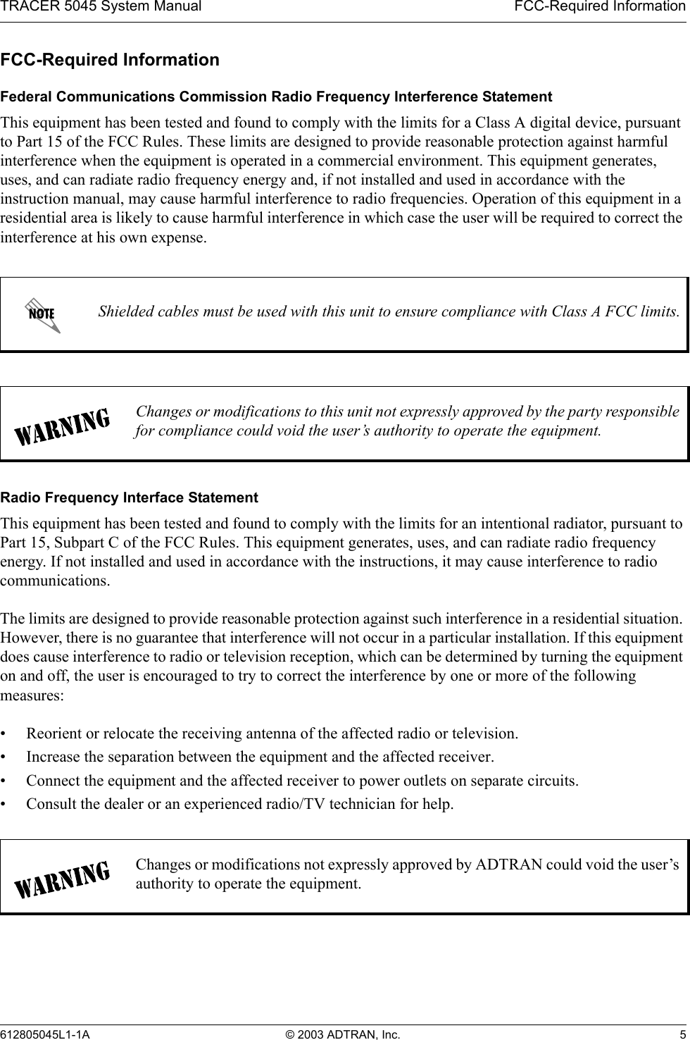
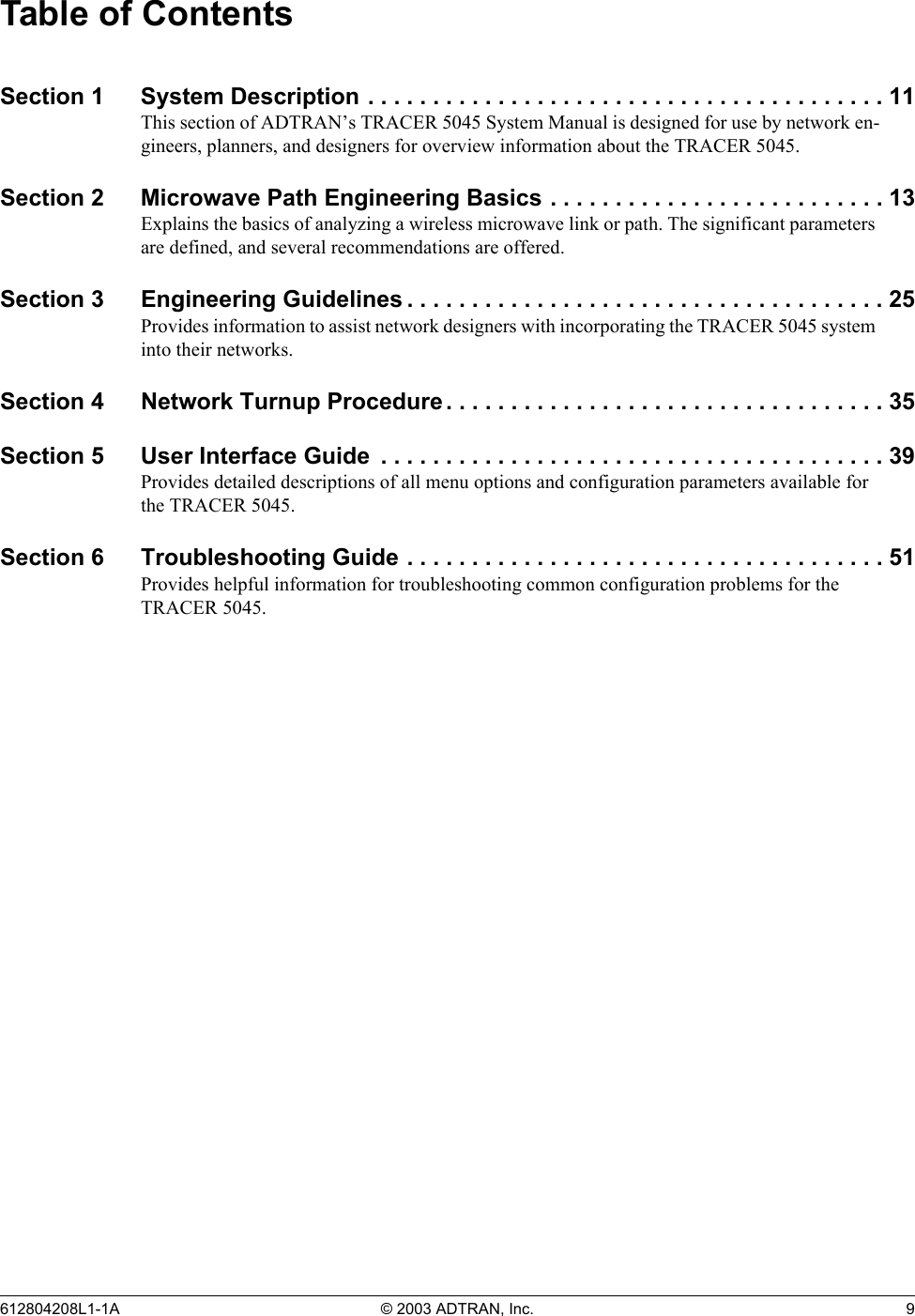
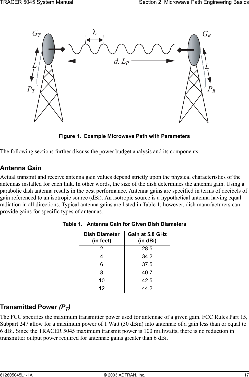
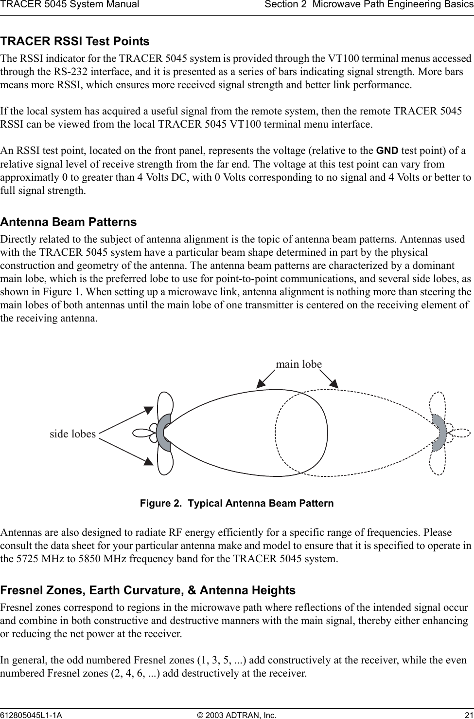
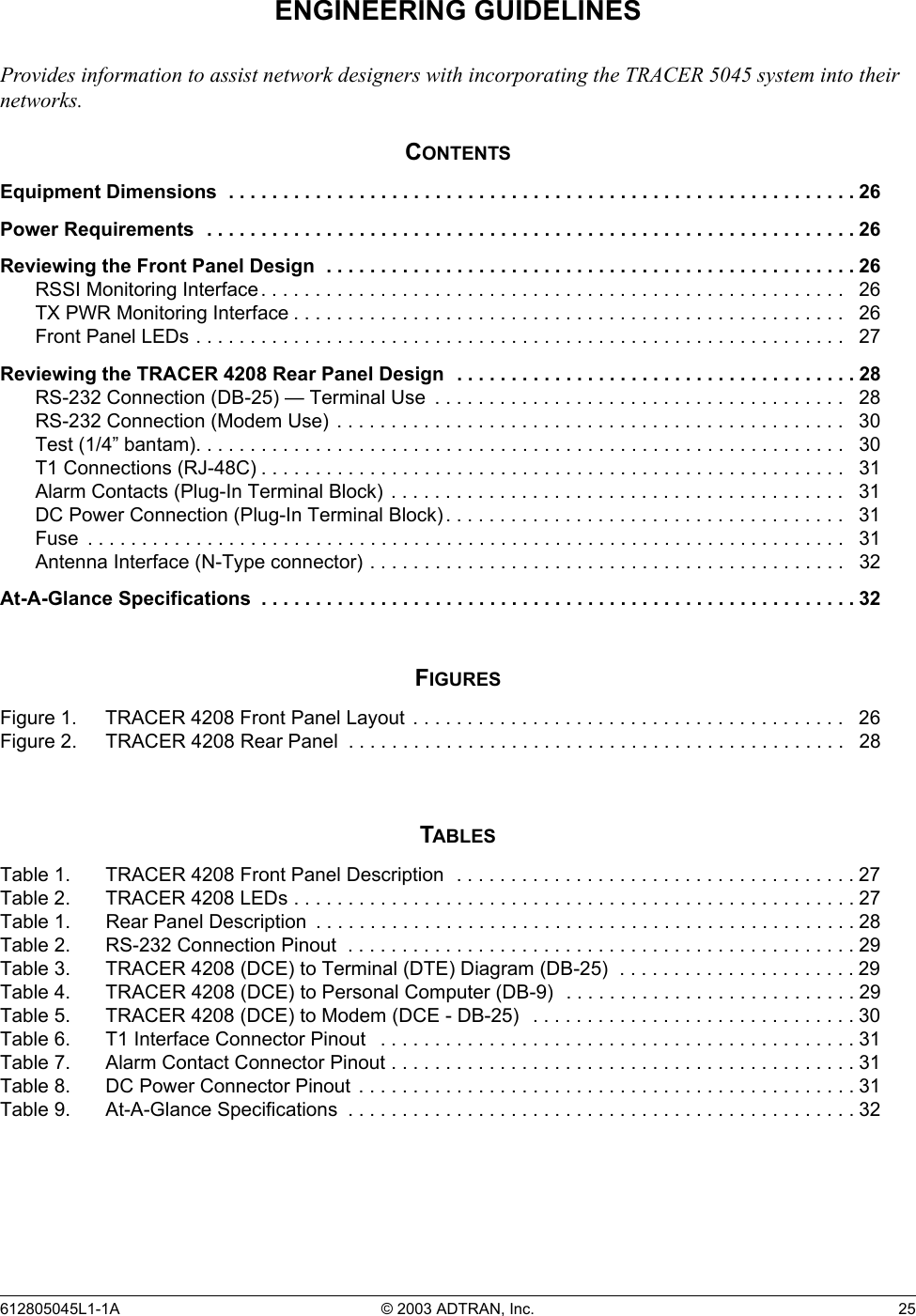
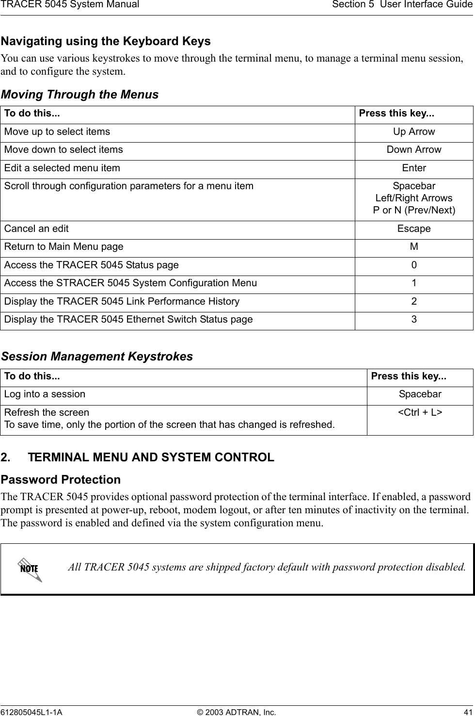
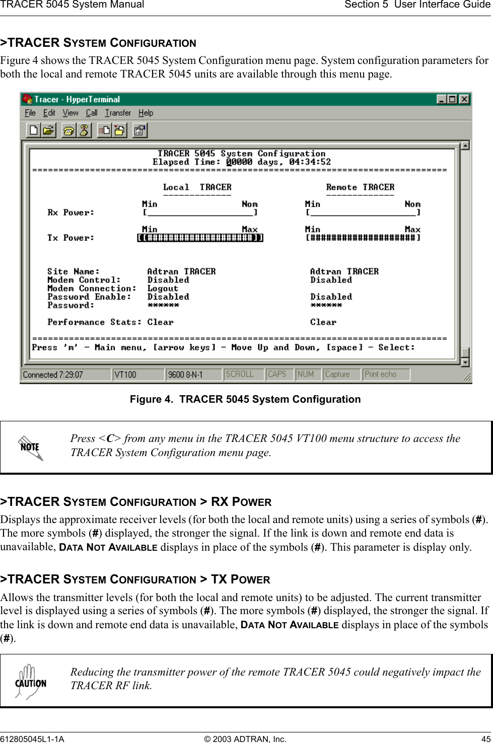
![TRACER 5045 System Manual Section 2 Microwave Path Engineering Basics612805045L1-1A © 2003 ADTRAN, Inc. 237. OTHER CONSIDERATIONSPath AvailabilityThe path availability of a wireless link is a metric that expresses the fractional amount of time a link is available over some fixed amount of time, and depends on several factors. Path availability is expressed aswhere the parameters areaterrain factorbclimate factorfcarrier frequency (GHz)dpath length (miles)Ffade margin (dB)Terrain Factor (a)The terrain factor is a quantity that compensates the link availability for different types of terrain. Generally speaking, the more smooth an area's terrain is, the less availability a wireless link running over that terrain will have, primarily due to multipath reflections. In contrast, secondary microwave signals will be randomly dispersed over rough terrain, and will not interfere with the main signal lobe as badly as in the smooth terrain case. The terrain factor values normally used are listed below:Climate Factor (b)The climate factor is a quantity that compensates the link availability for different types of climates (weather). In general, microwave links operating in areas with high humidity will have less availability than those in arid areas, primarily because water is a dispersive mechanism to microwave energy, and causes the main signal lobe to refract and disperse away from the receiver location. The climate factor values normally used are listed below:Terrain Terrain Factor DescriptionSmooth 4water, flat desertAverage 1moderate roughnessMountainous 1/4 very rough, mountainousClimate Climate Factor DescriptionVery Dry 1/8 desert regionsTemperate 1/4 mainland, interior regionHumid 1/2 humid and coastal regionsA12.5106–×()abfd310 F10⁄–()–[]100%×=(%)](https://usermanual.wiki/ADTRAN/TRC5045L1/User-Guide-455529-Page-23.png)