ADTRAN TRC582TR1 Point to Point Spread Spectrum System User Manual Title page
Adtran Point to Point Spread Spectrum System Title page
UserManual.wiki
>
ADTRAN
>
TRC582TR1 User Manual
Manual
Navigation menu
Upload a User Manual
Namespaces
Wiki Guide
HTML
PDF
Info
Views
User Manual
Discussion / Help
Navigation
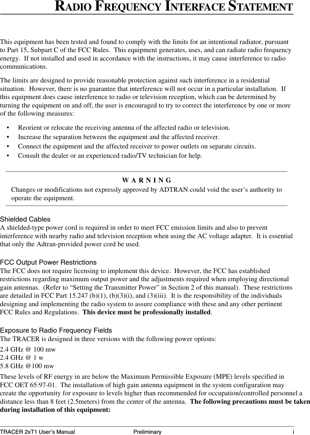
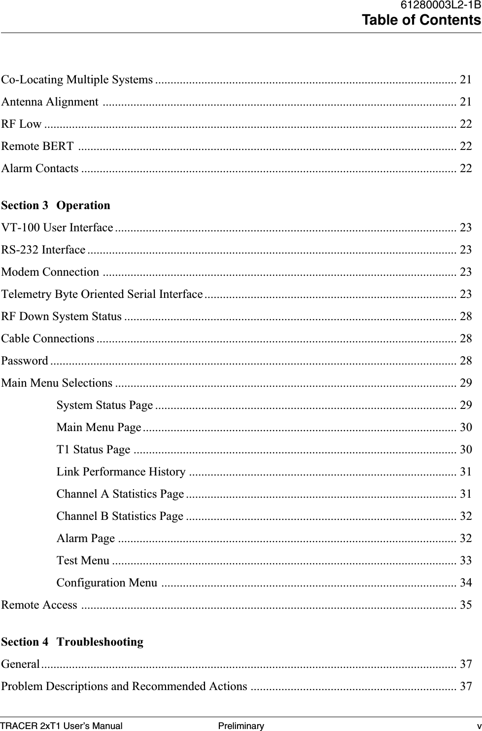
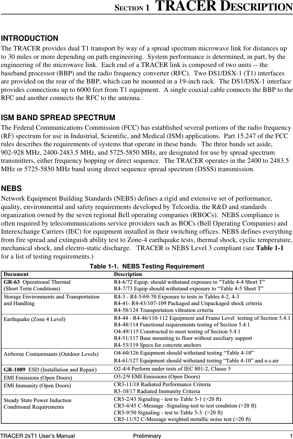
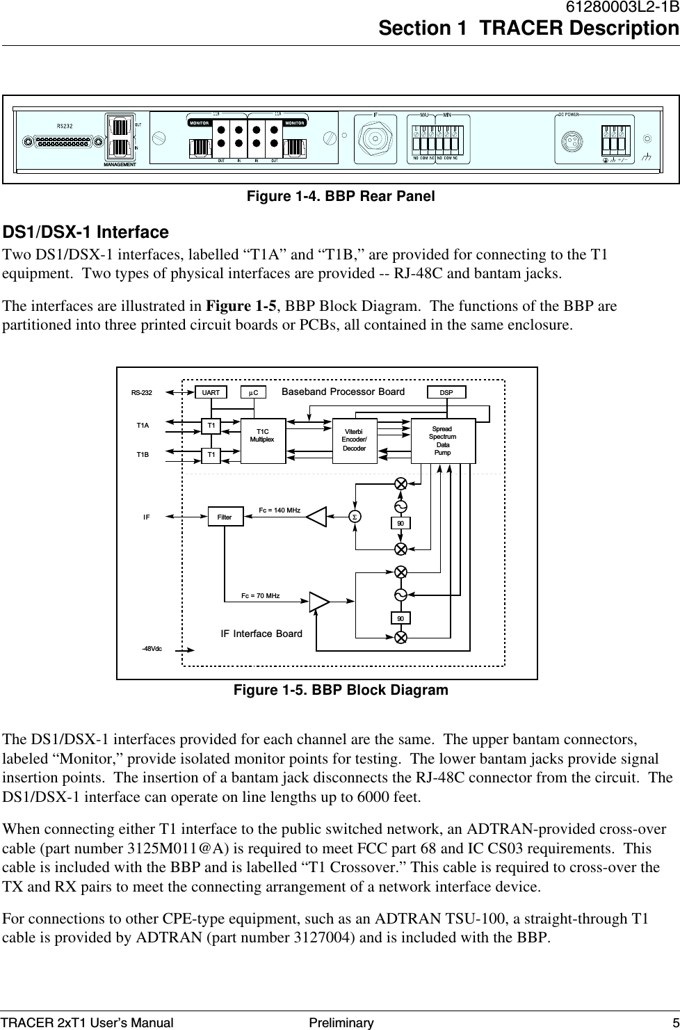
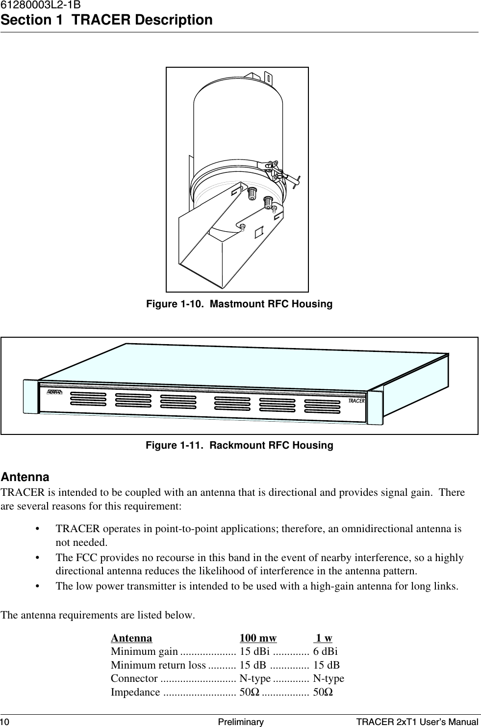
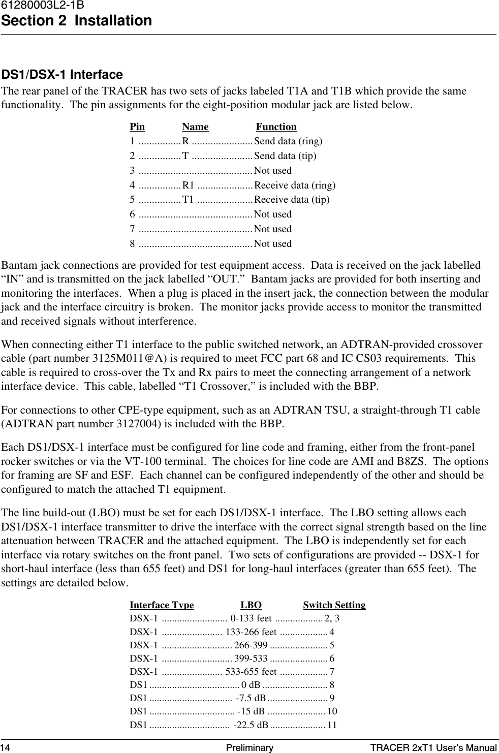
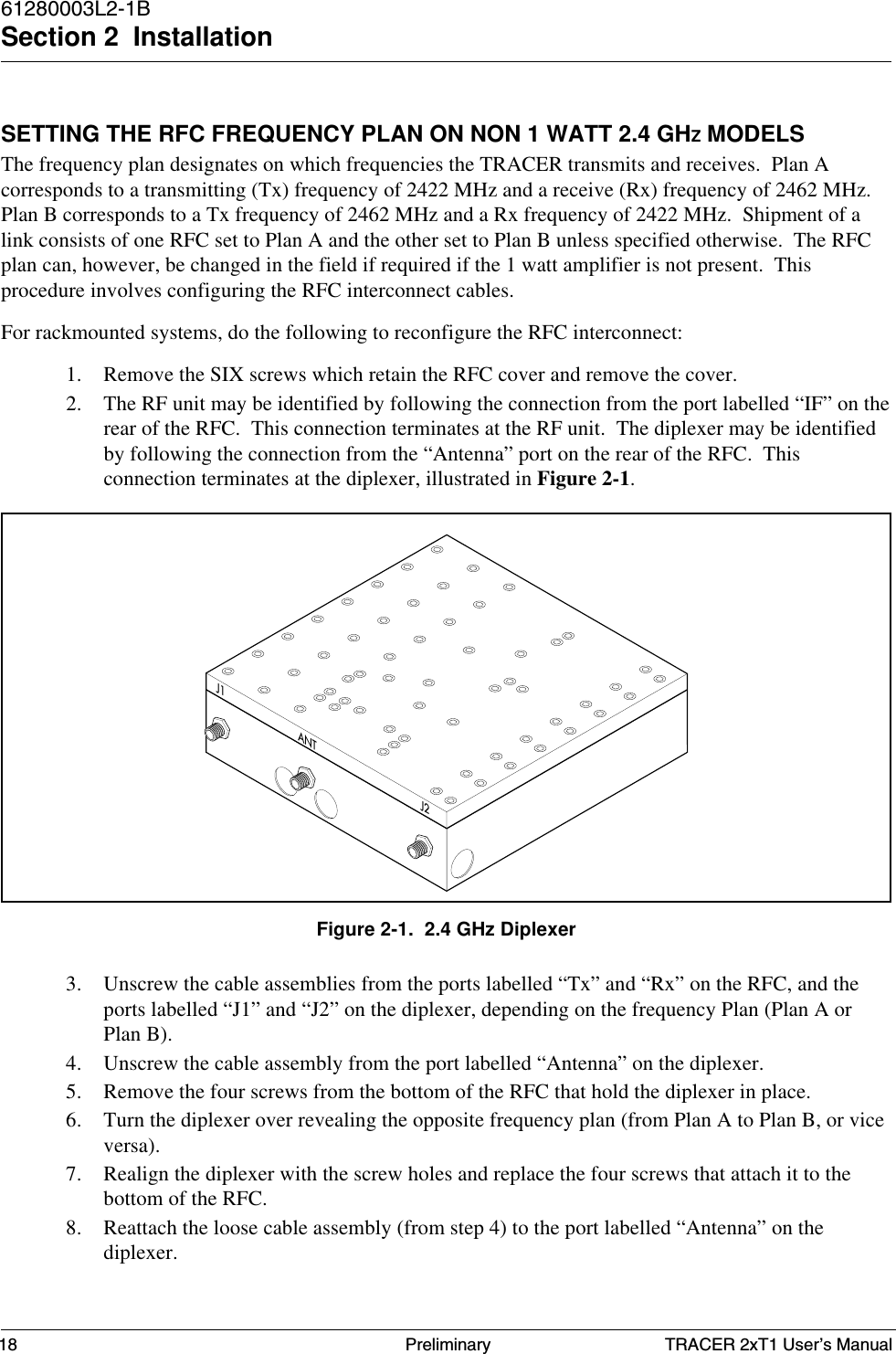
![TRACER 2xT1 User’s Manual61280003L2-1BSection 1 TRACER Description9PreliminaryThree SMA connectors, located on the RFC module, provide RF and IF connection points. A test point isprovided for monitoring the received signal strength indicator (RSSI). The voltage (relative to the GNDtest point) present on this test point represents the level of the received signal. This signal is used to alignthe antenna when installing the system and to verify the link is performing as designed. Another testpoint is provided to monitor the transmitter output power during system configuration. The onlyconnections that must be made in the field are a coax connection between the baseband processor and theRFC and a coax connection between the RFC and the antenna. These connections require male, type Ncoax connectors.The IF connector provides the connection between the baseband processor and the rackmounted ormastmounted RFC. (An 8-inch IF cable [ADTRAN part # 3125RF027@A] is provided for rackmountsystems). The TO ANTENNA connection provides the connection between the RFC and the antenna. Ablock diagram of the RFC functions is show in Figure 1-9.The RFC module is enclosed in either a 19-inch EIA rackmount housing, or a weather-tight enclosuresuitable for mastmounting near the antenna for enhanced system performance. The RFC mastmount andrackmount housings are illustrated in Figures 1-10 and 1-11.Figure 1-8. RFC ModuleRXTXIFRSSIGNDTX-PWRFigure 1-9. RFC Function Block DiagramSAW33323212281AGCSplitterSplitterAGCPALPFRF2IF2018 5344or2058 54245607or 5687TxRx](https://usermanual.wiki/ADTRAN/TRC582TR1/User-Guide-114868-Page-19.png)
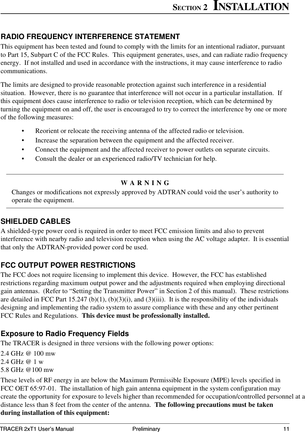
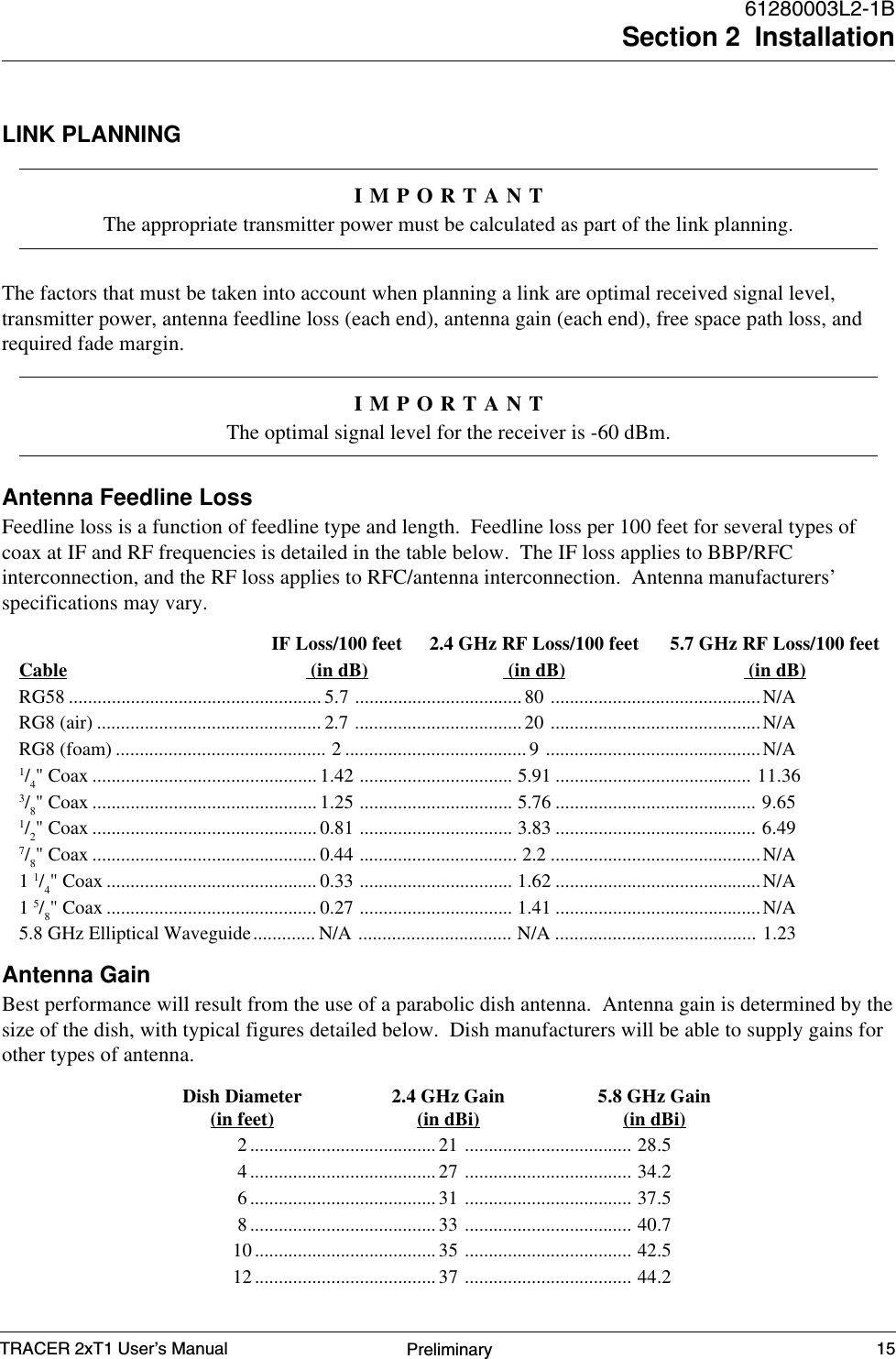
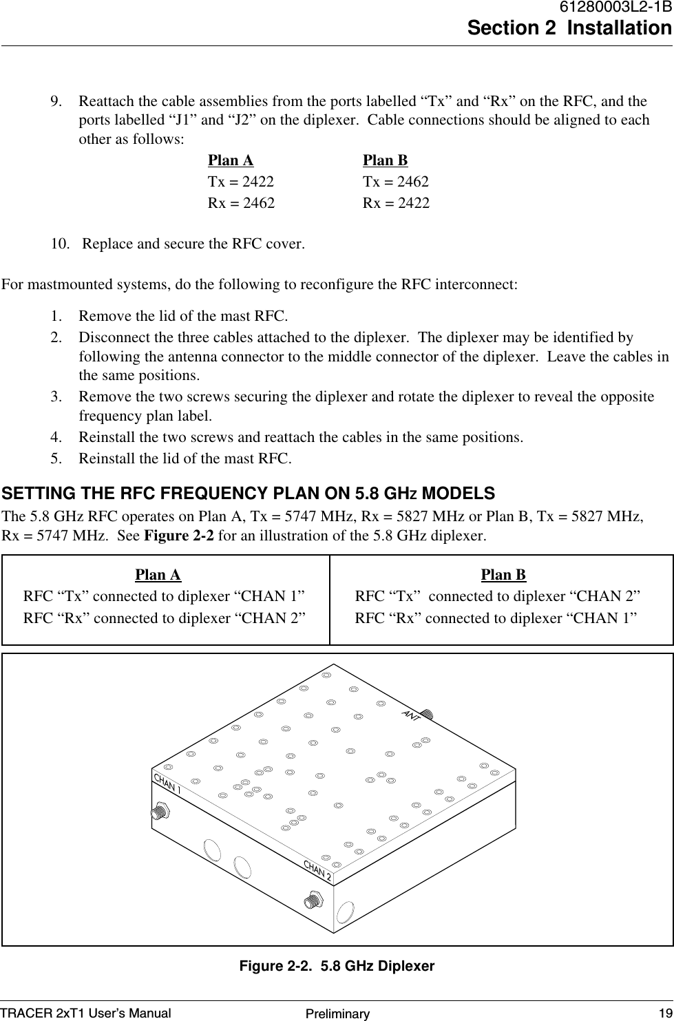
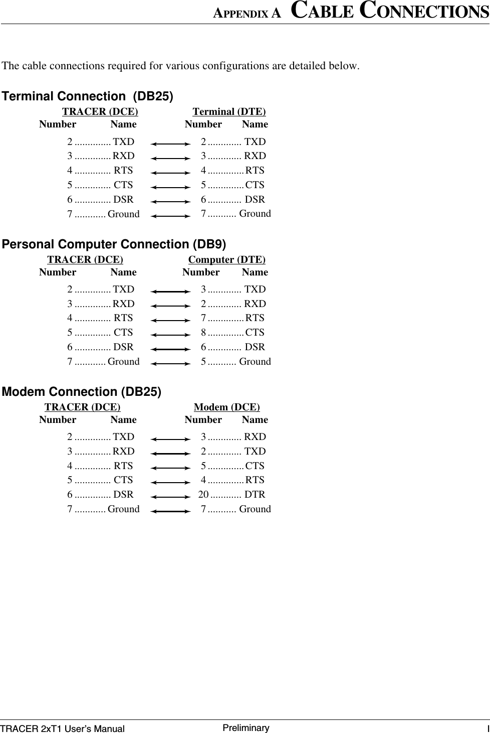
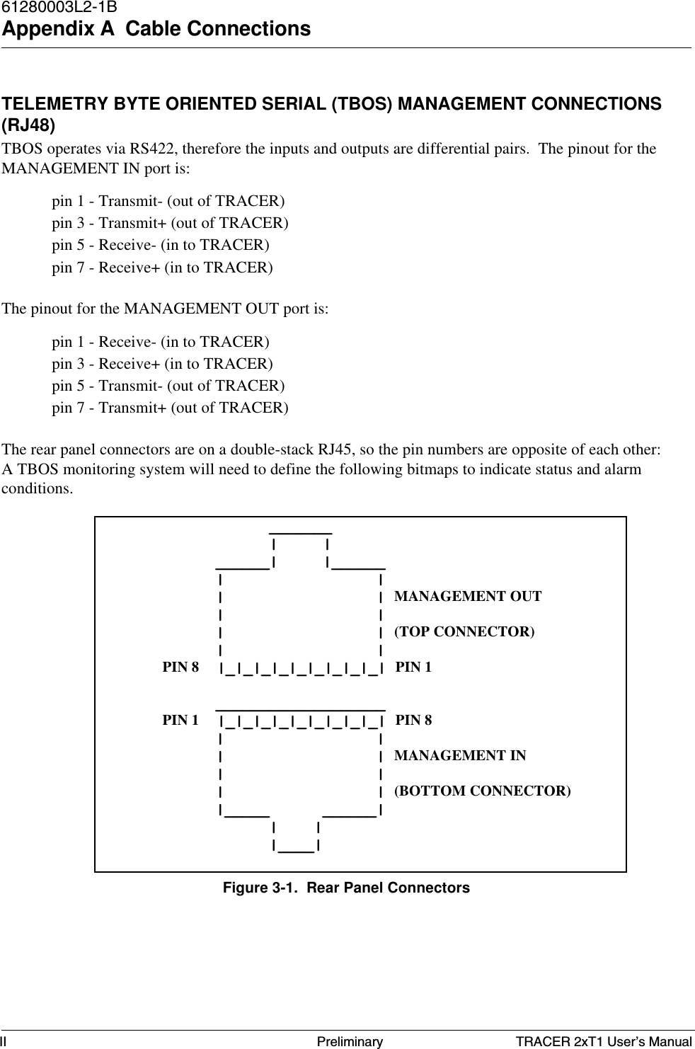
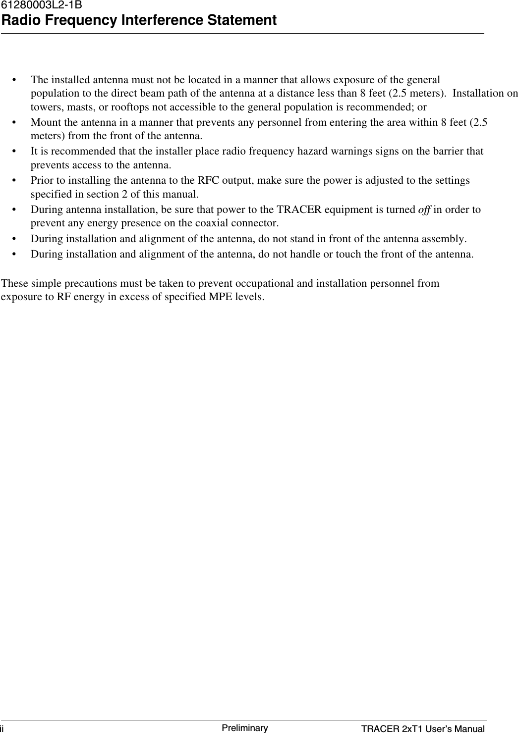
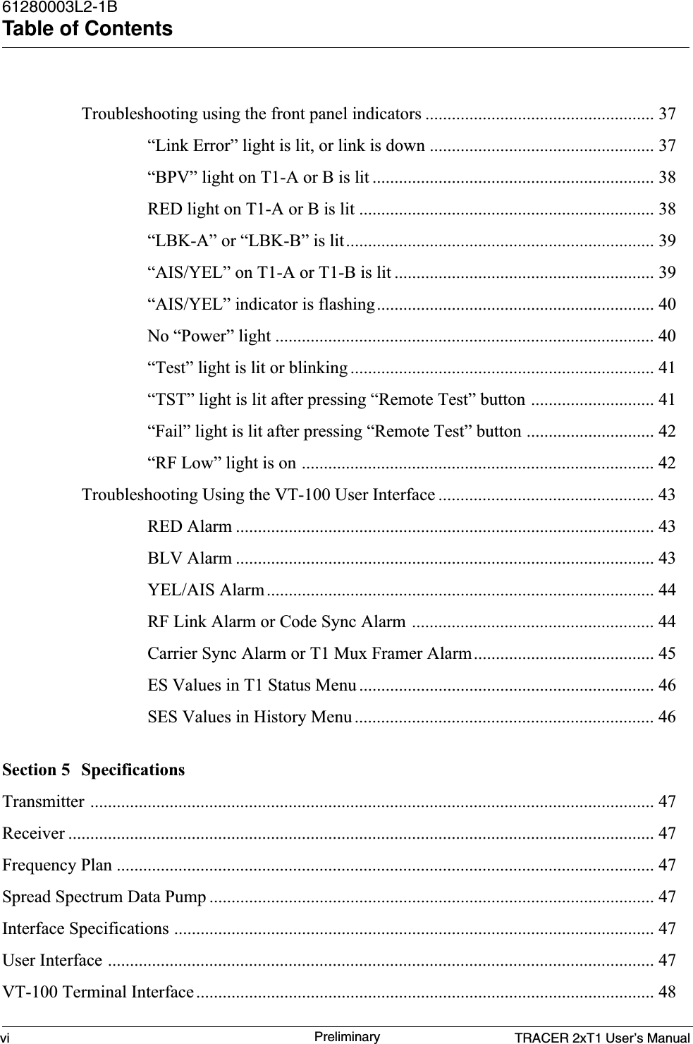
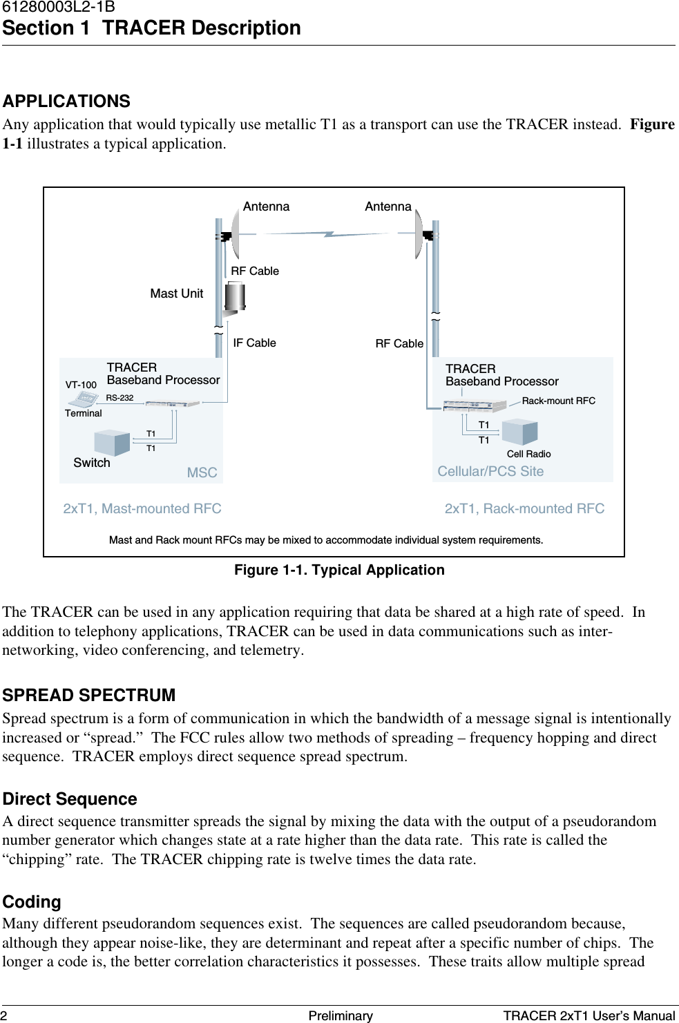
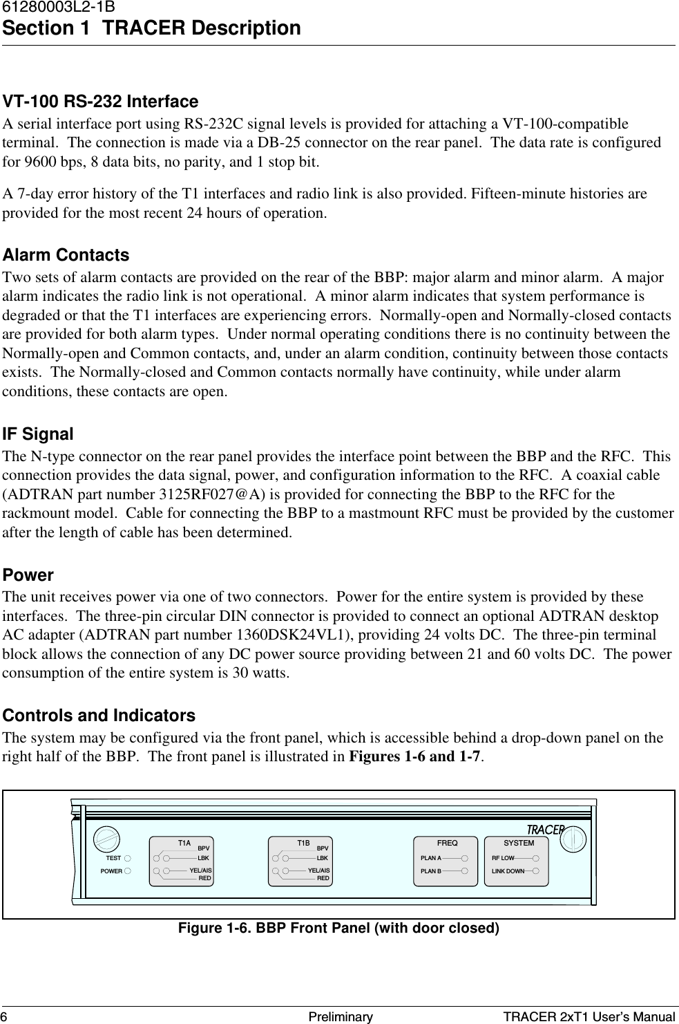
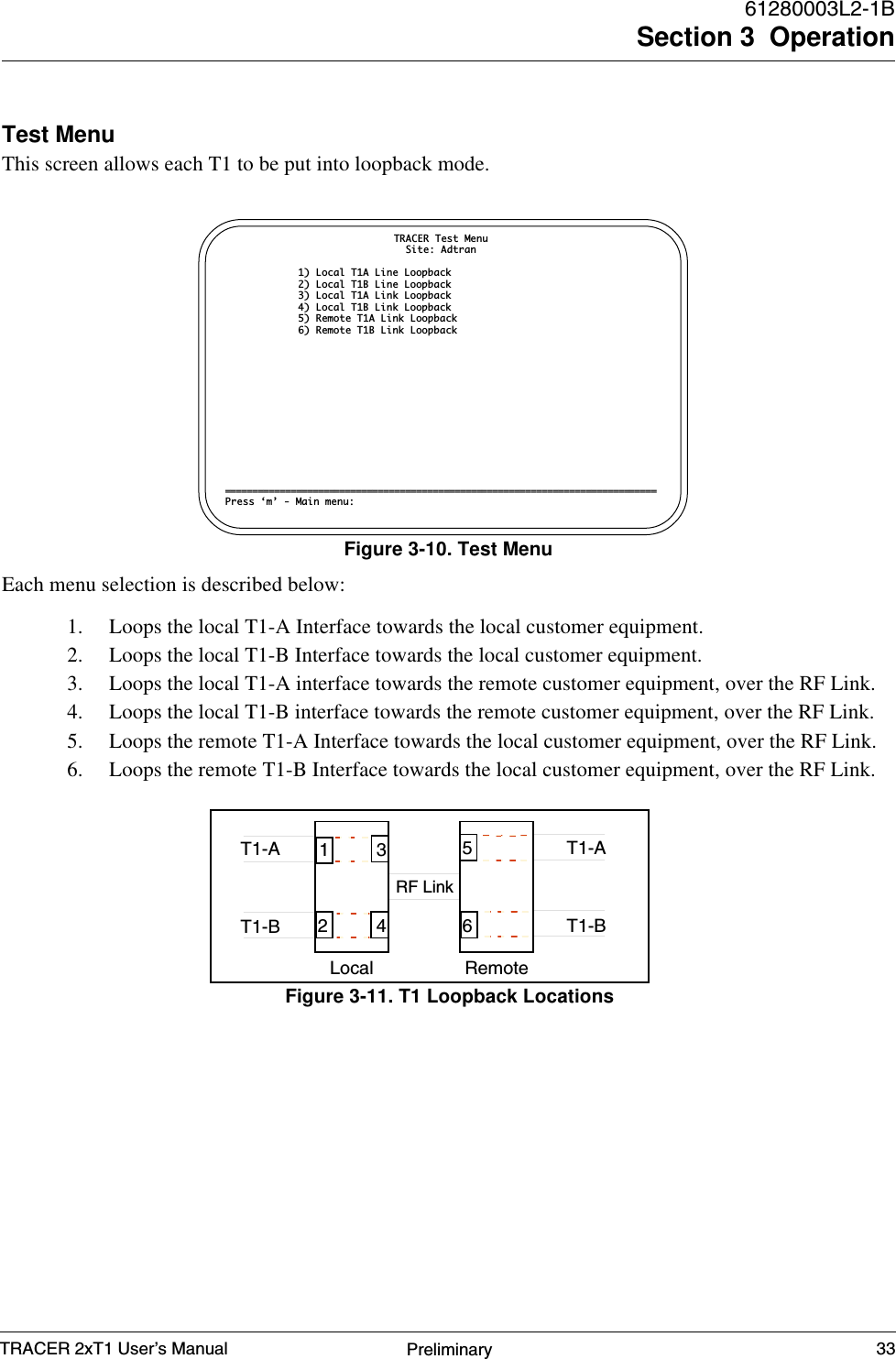
![VT-100 USER INTERFACEThe TRACER may be accessed with a VT-100 compatible terminal set to 9600 bits per second, 8 databits, and no parity, connected to the RS-232 port on the back of the unit. Once a terminal is connected,pressing the ESC key will present the System Status screen. If password access has been enabled, thenpress “Enter” or “Return” in order to see the “Enter Password:” message. TRACER is shipped withpassword protection disabled.RS-232 INTERFACEThe TRACER has an RS-232 interface for system management via an attached VT-100 terminal,personal computer, or modem. The RS-232 port is configured as a DCE with the following pinassignments:Signal PinName Number DirectionTXD 2 To TRACERRXD 3 From TRACERRTS 4 To TRACERCTS 5 From TRACERDSR 6 From TRACERGround 7DCD 8 To TRACERDTR 20 To TRACERMODEM CONNECTIONOption 16, discussed in the Configuration Menu page of this section, will enable or disable modemcontrol. When this option is enabled from a standard terminal connection, all RS-232 communicationswill cease until a modem is attached with a Null-Modem adapter between the TRACER and data modem.The data modem will need to be configured for AUTO ANSWER and 9600 BPS. When the userconnects via modem to the TRACER unit, communications via the RS-232 port will resume. If a useraccidentally enables modem control from a terminal and disrupts the RS-232 communication, pressing[CTRL Z] three times, will temporarily disable the modem control option. This will allow the user toaccess the configuration menu to disable modem control.When modem control is enabled, the RS-232 port is inactive until DTR and DCD are active. Thisprohibits data being sent to the modem or received from the modem while idle. The required Null-Modem adapter may be obtained at any computer hardware supplier. A straight-through serial cableshould be used between the adapter and the modem or TRACER unit. To ensure that the far-end modemdisconnects when desired, option 17 of the CONFIGURATION MENU will disconnect the modem. Themodem must be configured to drop the connection on loss of DTR in order to disconnect.TELEMETRY BYTE ORIENTED SERIAL (TBOS) INTERFACEE-telemetry systems were developed by the pre-divestiture AT&T organization as a method to monitorand control diverse network elements from a remote, centralized location. Status and command remote(SAC) units were employed in the central office to convert discrete (contact closure) alarms frommonitored equipment into E-telemetry for efficient transfer of data to and from the operations center.SECTION 3 OPERATIONTRACER 2xT1 User’s Manual 23Preliminary](https://usermanual.wiki/ADTRAN/TRC582TR1/User-Guide-114868-Page-33.png)
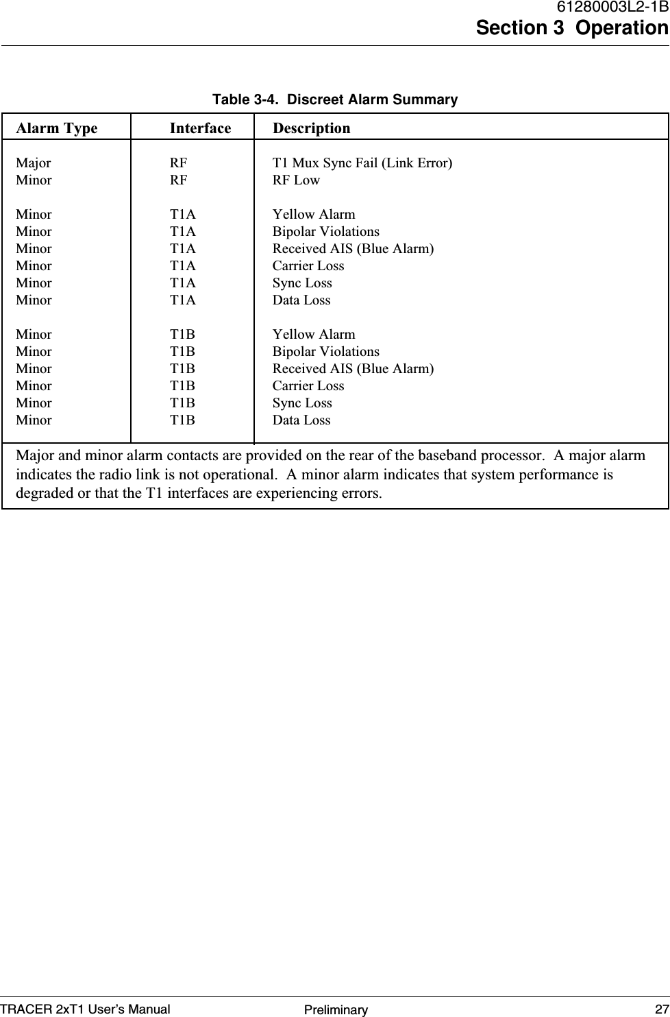
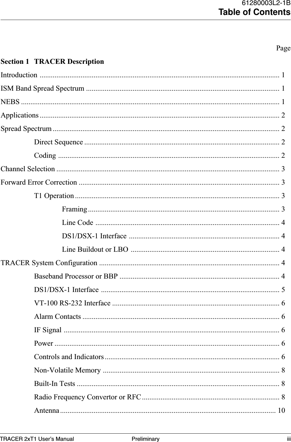
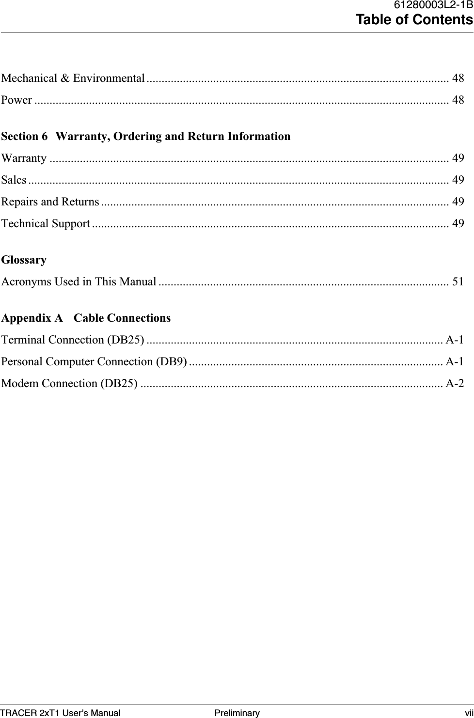
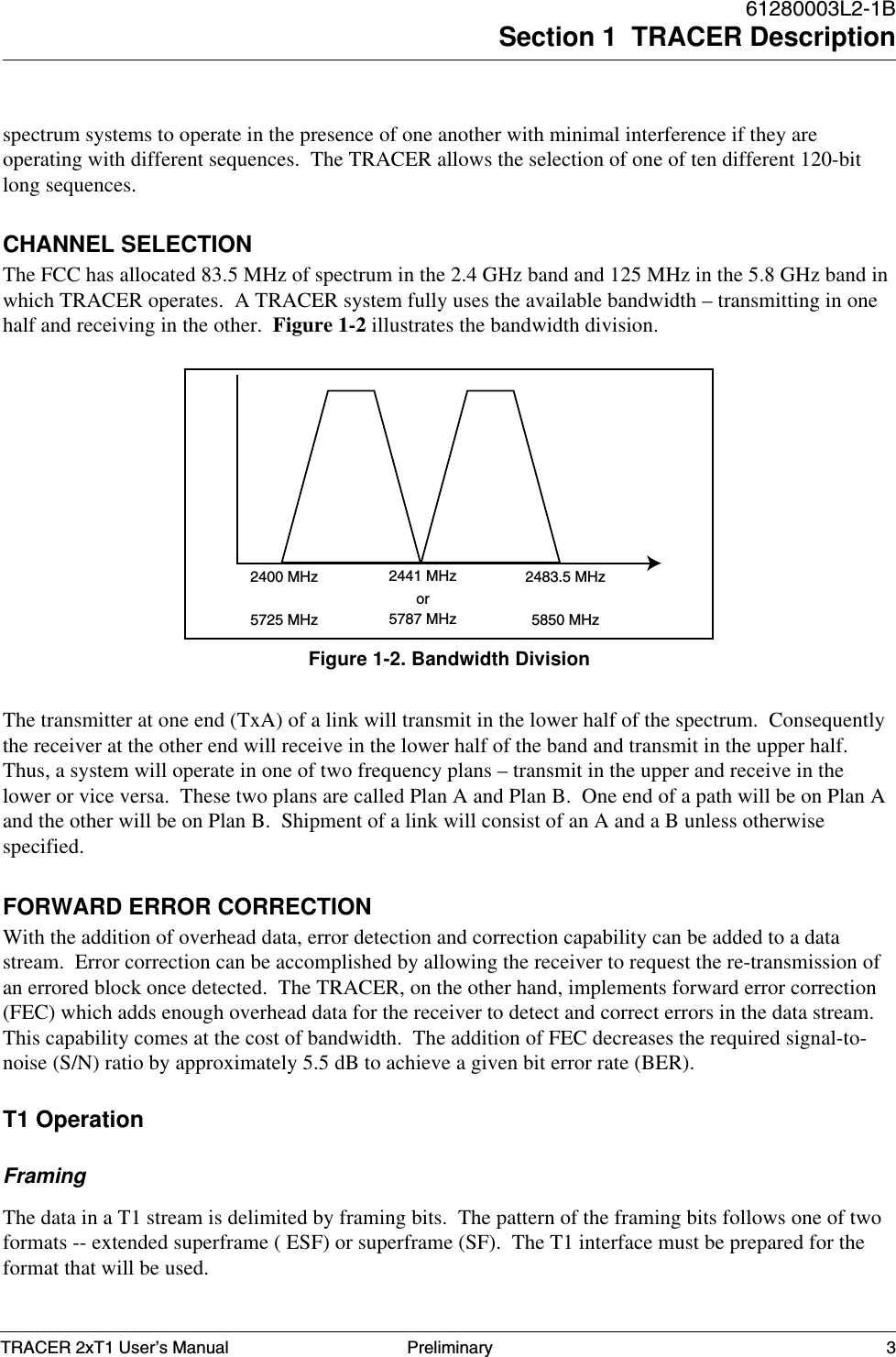
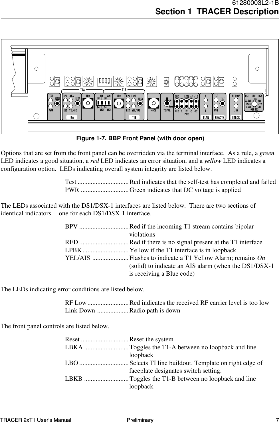
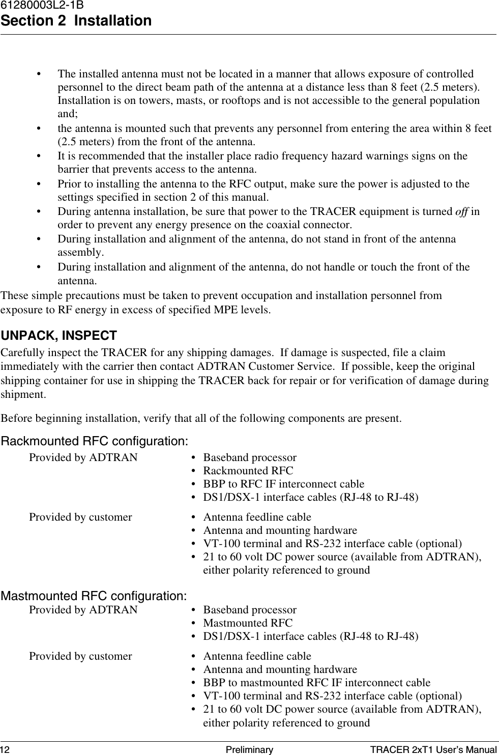
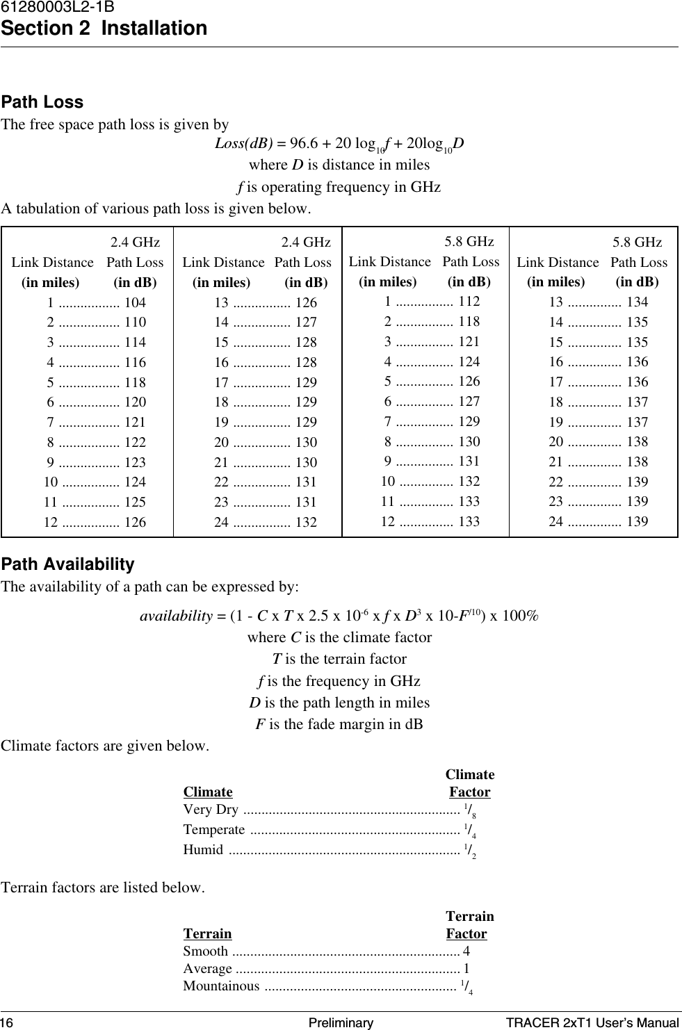
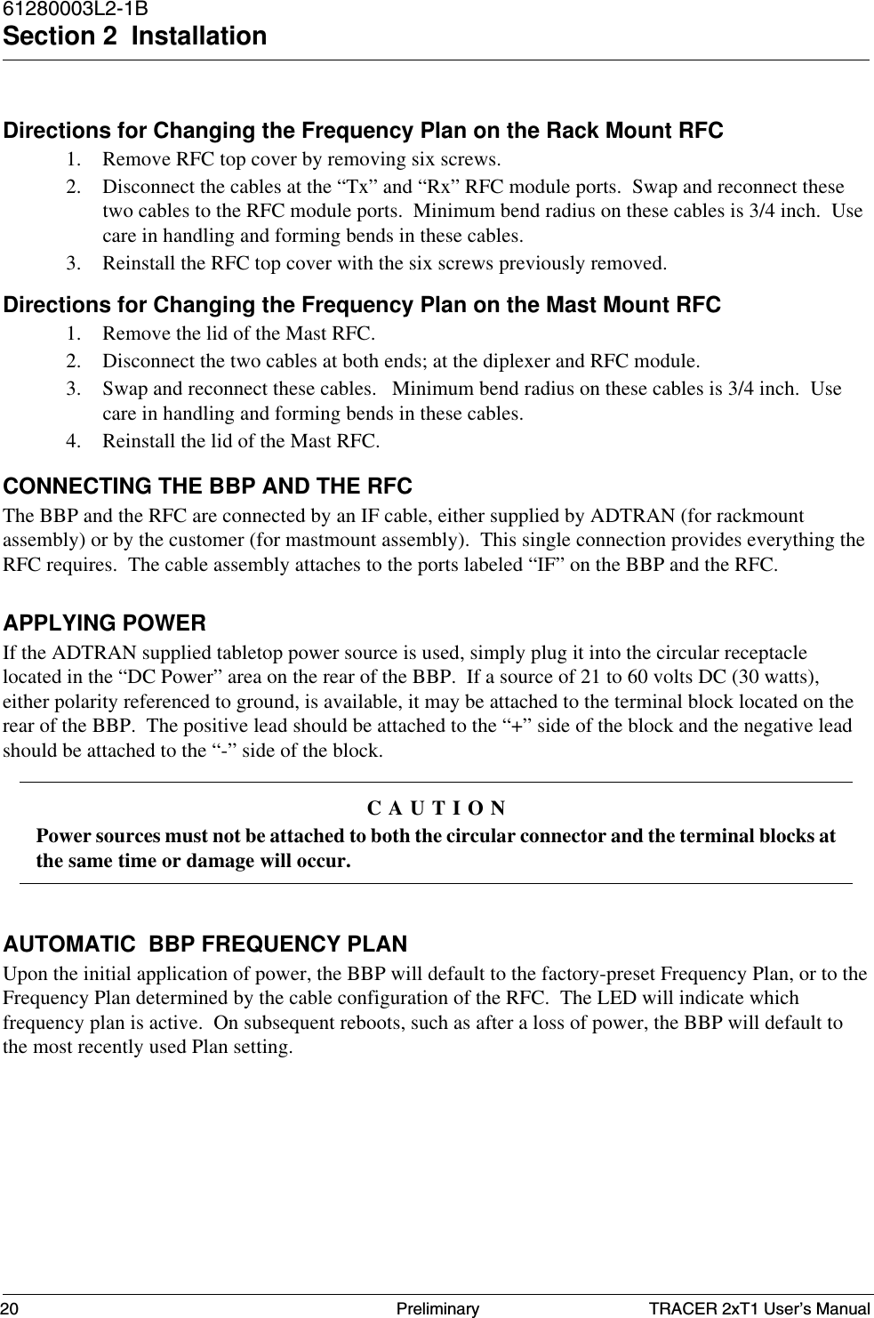
![TRACER 2xT1 User’s Manual61280003L2-1BSection 3 Operation28 PreliminaryRF DOWN SYSTEM STATUSIf there is an error condition on the RF link, the [RF UP] labels on the link map will be replaced by [RFDOWN] or [?????] labels. During a RF error condition, it is not possible to receive status informationfrom the remote site. However, when the RF link is intact, error conditions on any of the T1 interfacesare reported by the “T1A” and / or “T1B” labels becoming highlighted in reverse video. If the error is onthe local TRACER, the T1 status menu can be accessed for complete alarm information. If the error ison the remote unit, remote access can be utilized (via another menu option) to check the status of the T1interfaces at the remote end.CABLE CONNECTIONSThe cable connections required for various configurations are detailed in Appendix A of this manual.PASSWORDTRACER provides optional password protection of the terminal interface. If enabled, a passwordprompt is presented at power-up, reboot, or after thirty minutes of inactivity on the terminal. The defaultconfiguration is “No password.” Password protection is enabled via the configuration menu. Thepassword is also set via the configuration menu.If the password is forgotten, physical access to TRACER is required to access the terminal interface.The password may be bypassed by holding in the LPBK A button while the system is rebooted. This willbring up the terminal interface and allow the password to be changed or disabled via the configurationscreen.CAUTIONThis procedure is service-affecting.Figure 3-2. System Status PageCurrent System StatusElapsed Time 00:01:09 -——- Adtran Technical Support - 800/726-8663 --——T1AT1A ===| | / ->>--——>>—--—>>—--[??????]—--—>>—--—>>—--—>>-> \ | |=== T1A | |#(- -)# | |T1BT1B ===| | \ -<<—--—<<—--—<<—--[RF DOWN]—--—<<—--—<<—--—<<- / | |=== T1B ——-- -—-— Local Tracer Remote Tracer Freq Plan A Freq Plan ? Tx Pwr Rx Pwr Tx Pwr Rx Pwr Max [X] [ ] Nominal Max [?] [?] Nominal [X] [ ] [?] [?] [X] [ ] Site: ADTRAN [?] [?] [X] [ ] [?] [?] [X] [ ] RFC Link Up: Yes [?] [?] [X] [ ] Code Sync: No [?] [?] [X] [ ] Carrier Sync: NoNo [?] [?] [X] [ ] T1 Mux Sync: Noo [?] [?] [X] [ ] Chipping Code: 0 [?] [?] [X] [ ] [?] [?] Min [X] [ ] Min Min [?] [?] Min===========================================================================Press ‘m’ - Main menu:](https://usermanual.wiki/ADTRAN/TRC582TR1/User-Guide-114868-Page-38.png)
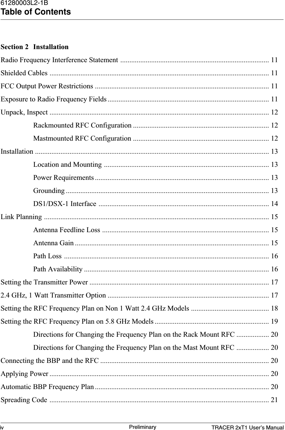
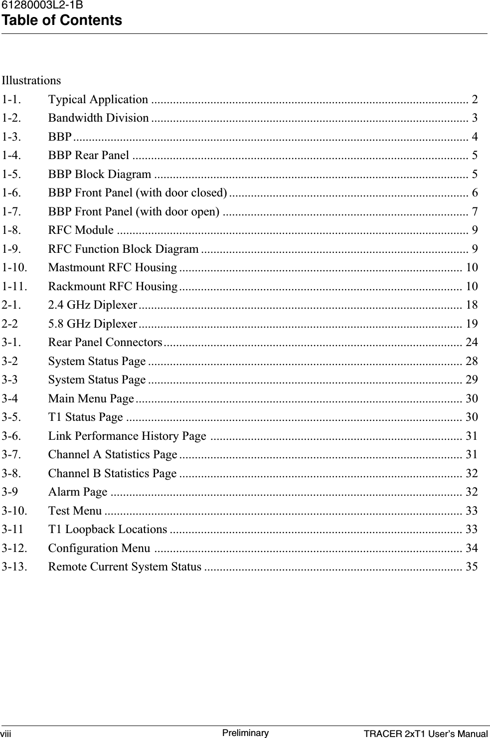
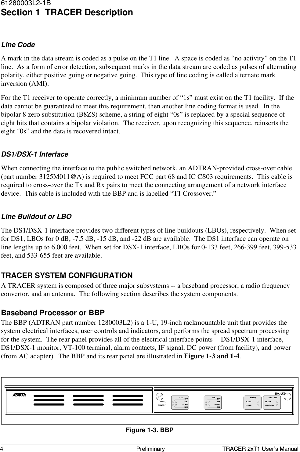
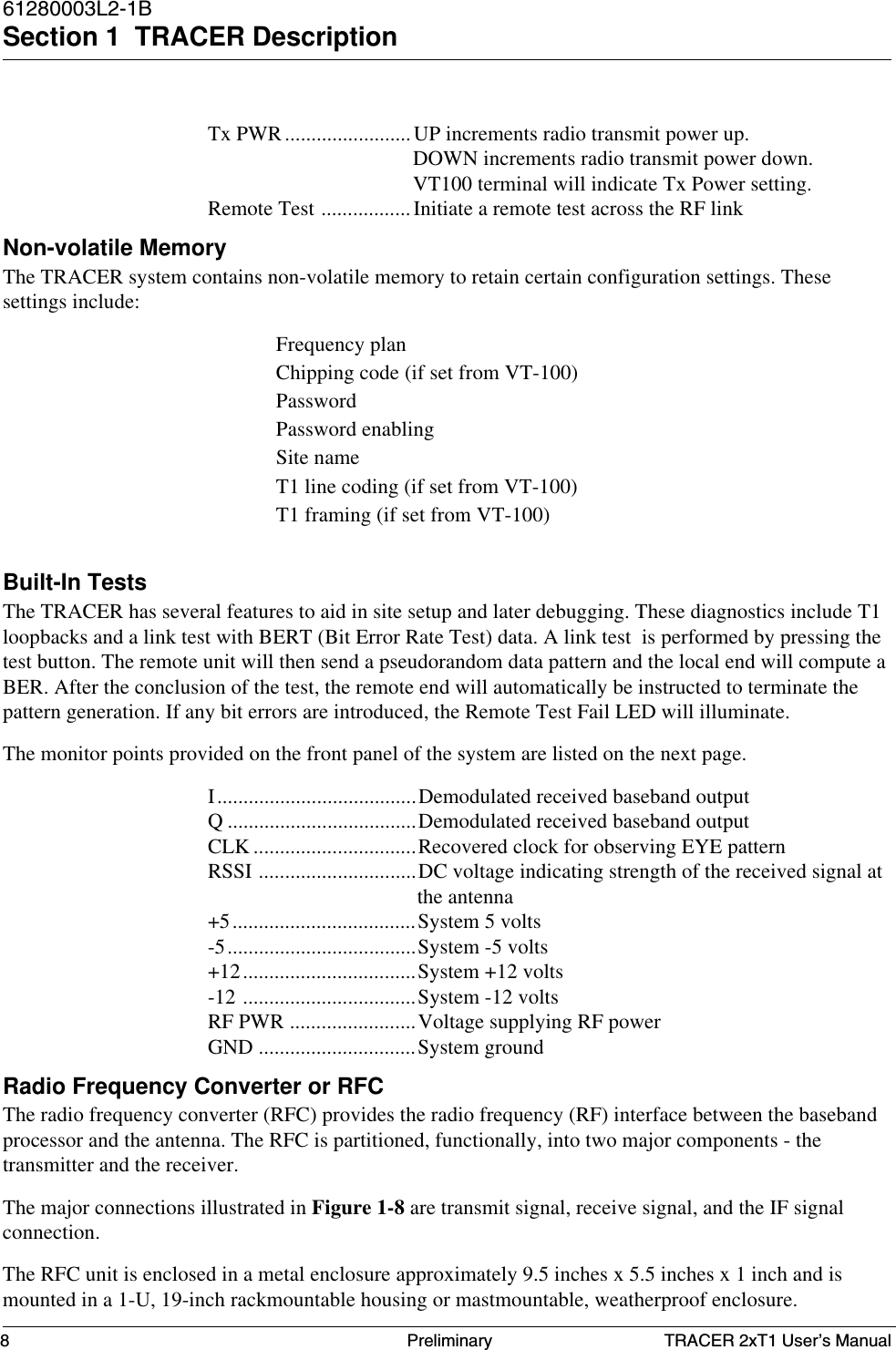
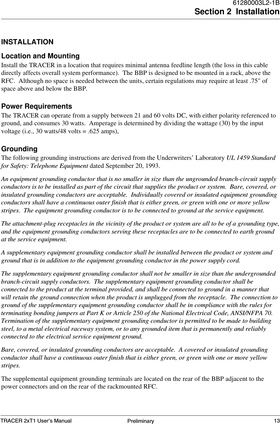
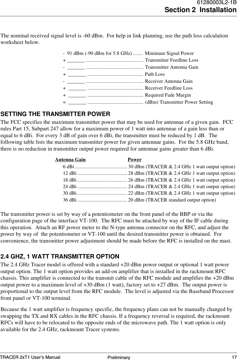
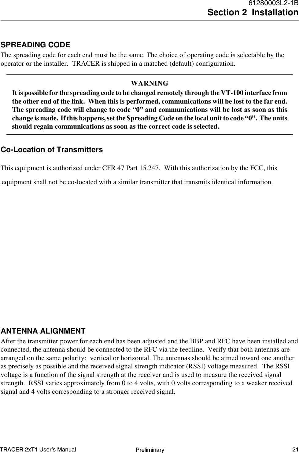
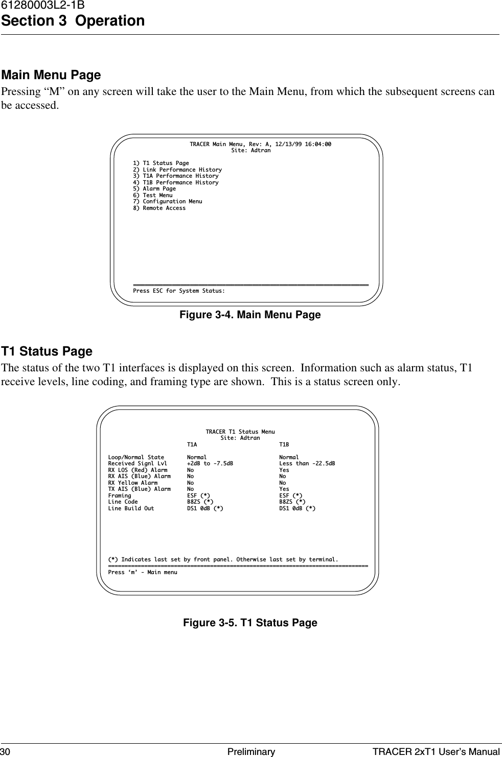
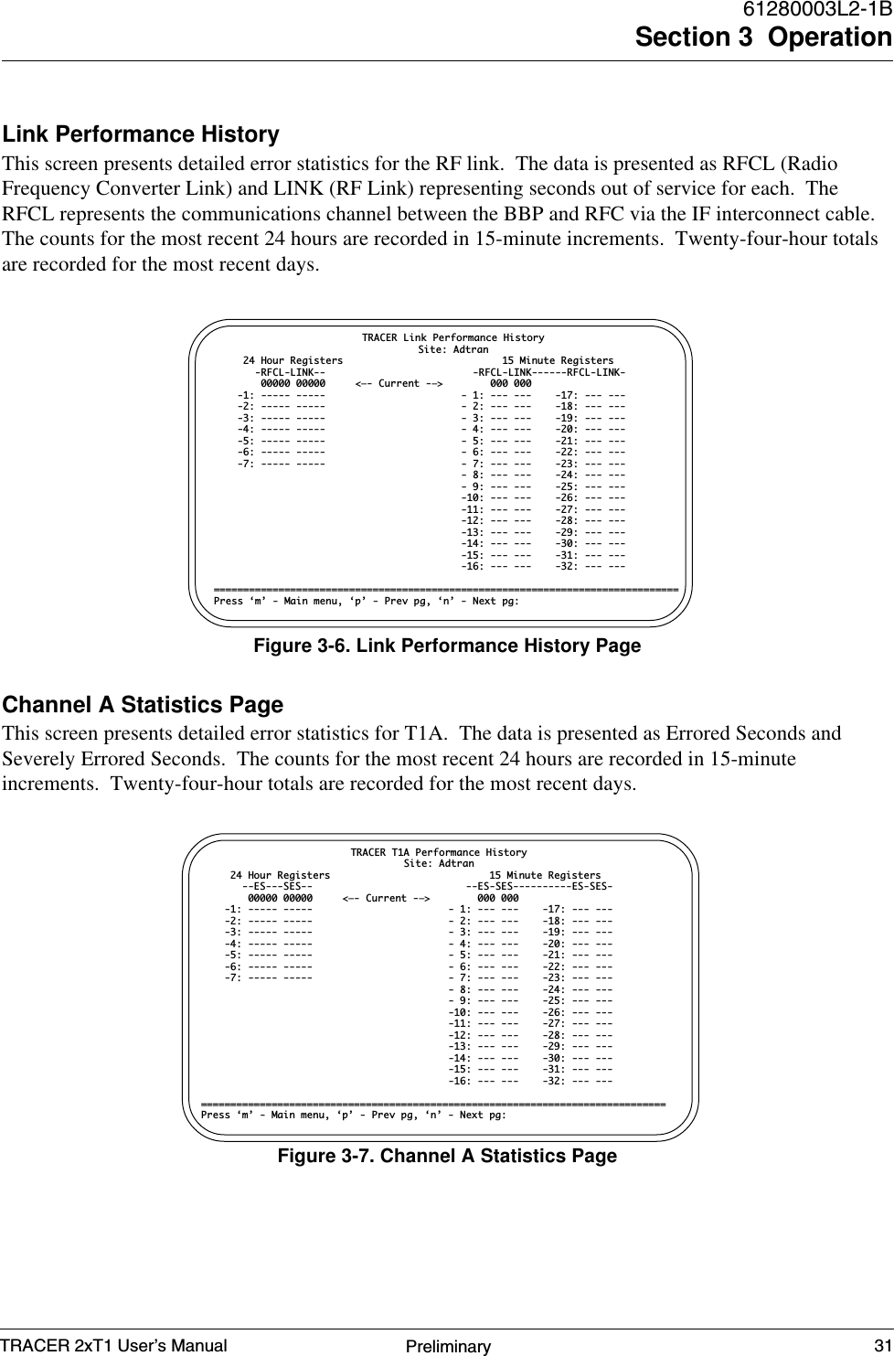
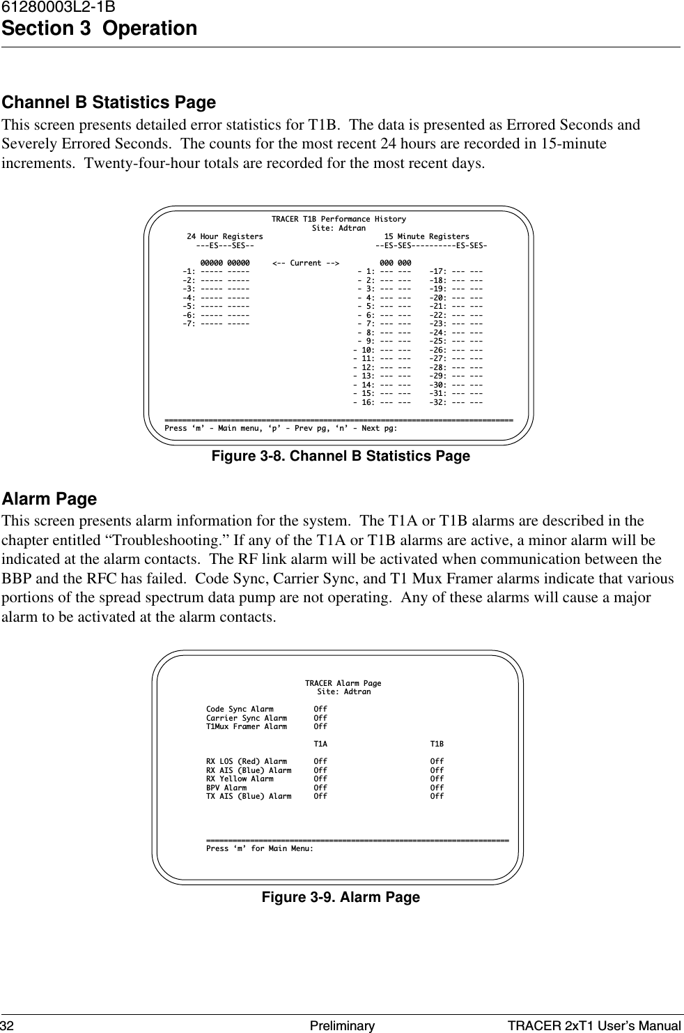
![TRACER 2xT1 User’s Manual61280003L2-1BSection 3 Operation29PreliminaryMAIN MENU SELECTIONSSystem Status PageThis page displays the status of major system components. This is a status screen only; noconfigurations can be performed. More detailed information can be obtained by way of the Main Menu.The upper portion of the screen indicates how long the system has been running since the last resetoperation. The “T1A” and “T1B” labels will be highlighted if any error conditions exist on that T1interface.The status of the radio link is indicated as Up or Down. The left portion of the screen reports the statusof the local system (the system to which the terminal is attached); the right portion reports the status ofthe remote system. The approximate transmitter and receiver signal levels are shown via the “fuelgauges.” If the link is down and remote end data is unavailable, the fuel gauges will show “-” instead of“x.” The Code Sync, Carrier Sync, and T1 Mux Sync will all be “yes” for an operational link. Chippingcode indicates the code to which the system is set. At any point in the VT-100 menu structure, pressingthe Escape key will bring the operator back to this screen.Figure 3-3. System Status PageCurrent System StatusElapsed Time 00:03:22Adtran Technical Support- 800/726-8663 ---—— -----T1A ===| C | / --—>>—--—>>—--—>>-—[RF UP]->>—--—>>—--—>>—--—> \ | C |=== T1A | S |#(- -)#| S |T1B ===| U | \ <—--—<<—--—<<—--—<<[RF UP]—--<<—--—<<—--—<<—-- / | U |=== T1B ---—— ——--- Local Tracer Remote Tracer Freq Plan A Freq Plan B Tx Pwr Rx Pwr Tx Pwr Rx Pwr Max [X] [X] Nominal Max [X] [X] Nominal [X] [X] [X] [X] [X] [X] Site: ADTRAN [X] [X] [X] [X] [X] [X] [X] [X] RFC Link Up: Yes [X] [X] [X] [X] Code Sync: Yes [X] [X] [X] [X] Carrier Sync: Yes [X] [X] [X] [X] T1 Mux Sync: Yes [X] [X] [X] [X] Chipping Code: 0 [X] [X] [X] [X] [X] [X] Min [X] [X] Min Min [X] [X] Min===============================================================================Press ‘m’ - Main menu:](https://usermanual.wiki/ADTRAN/TRC582TR1/User-Guide-114868-Page-39.png)
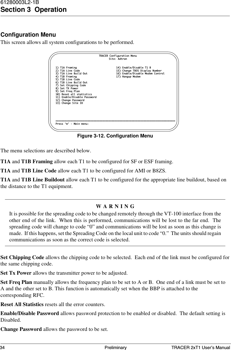
![TRACER 2xT1 User’s Manual61280003L2-1BSection 3 Operation35PreliminaryRemote Current System StatusElapsed Time 00:21:13 ----- ADTRAN Technical Support - 256/963-8716 ----- | C | / ->>---->>---->>--->[RF UP]>---->>---->>---->>- \ | C | T1 ===| S |#(- -)#| S |=== T1 | U | \ -<<----<<----<<----[RF UP]<----<<----<<----<<- / | U | ----- ----- Local Tracer Remote Tracer Freq Plan B Freq Plan A Tx Pwr Rx Pwr Tx Pwr Rx Pwr Max [ ] [X] Nominal Max [ ] [X] Nominal [ ] [X] [ ] [X] [ ] [X] Site: Adtran [ ] [X] [ ] [X] [ ] [X] [X] [X] RFC Link Up: Yes [X] [X] [X] [X] Code Sync: Yes [X] [X] [X] [X] Carrier Sync: Yes [X] [X] [X] [X] E1 Link Sync: Yes [X] [X] [X] [X] Chipping Code: 9 [X] [X] [X] [X] [X] [X] Min [X] [X] Min Min [X] [X] Min==============================================================================Press 'm' - Main menu, '~' to exit remote mode:Figure 3-13. Remote Current System StatusSite ID allows a string of up to 32 characters to be entered as a site identifier.Enable T1 B disables Alarm and LEDs related to T1-B, but will pass T1 data.TBOS # changes the TBOS Equipment ID.Enable Modem Control enables modem control leads on RS 232 port. See Modem Connection underOperation Section.Hangup Modem lowers the DSR signal, which becomes DTR after passing through the null modemadapter. When modem is configured to disconnect on loss of DTR, the connection will drop.REMOTE ACCESSThis allows access to the remote radio via the RF communications link. When accessed, the user will beable to identify remote mode by each screen titled "Remote." The remote menus are accessed via a 2400bps link causing screen refresh to be slower than local mode. All pages are displayed as if the user wereconnected to the VT-100 terminal at the remote end of the link. Every screen that can be accessed at thelocal radio can be accessed at the remote radio via this option.](https://usermanual.wiki/ADTRAN/TRC582TR1/User-Guide-114868-Page-45.png)