ADTRAN TRC6320 TRACER 6000 Series Split System User Manual 612806320L1 1A
Adtran TRACER 6000 Series Split System 612806320L1 1A
UserManual.wiki
>
ADTRAN
>
TRC6320 User Manual
Manual rev
Navigation menu
Upload a User Manual
Namespaces
Wiki Guide
HTML
PDF
Info
Views
User Manual
Discussion / Help
Navigation
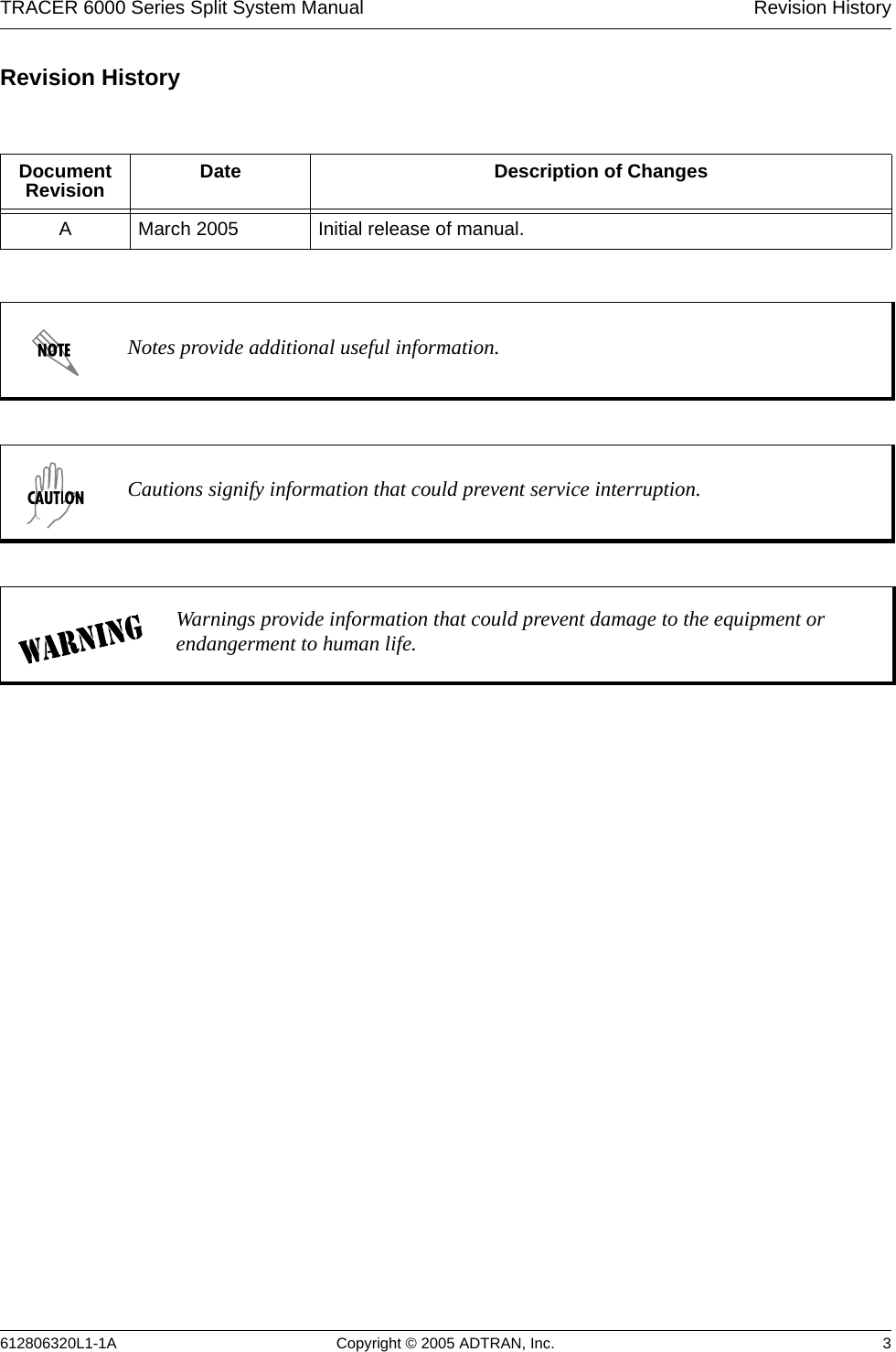

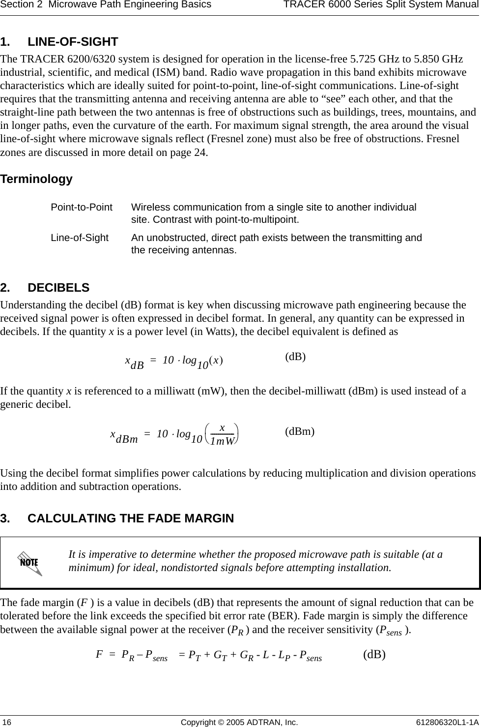
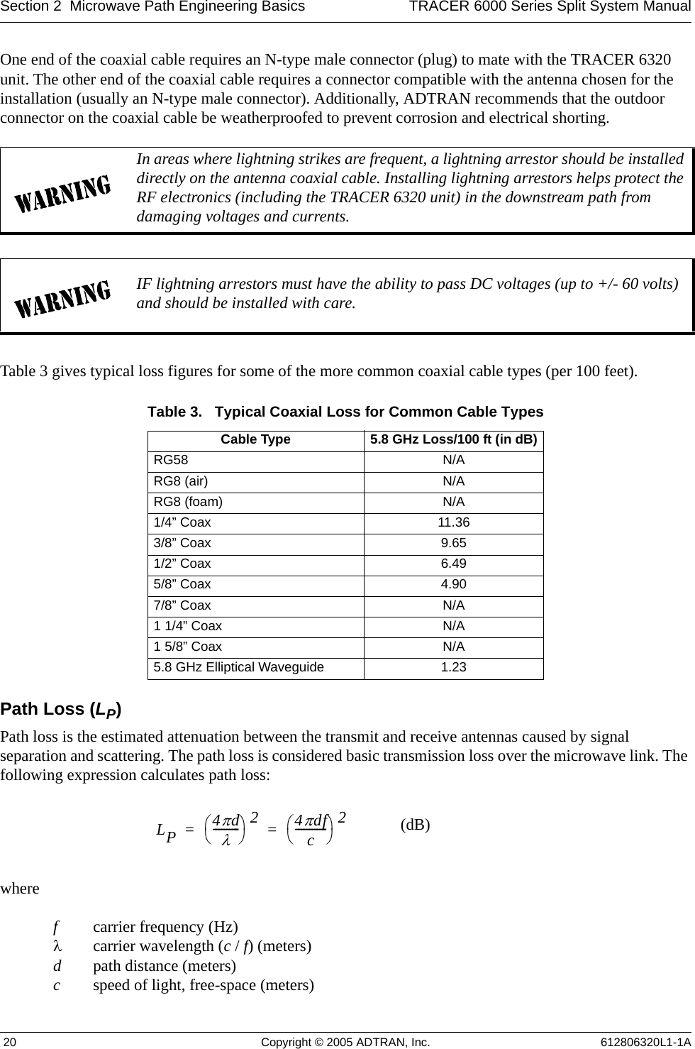

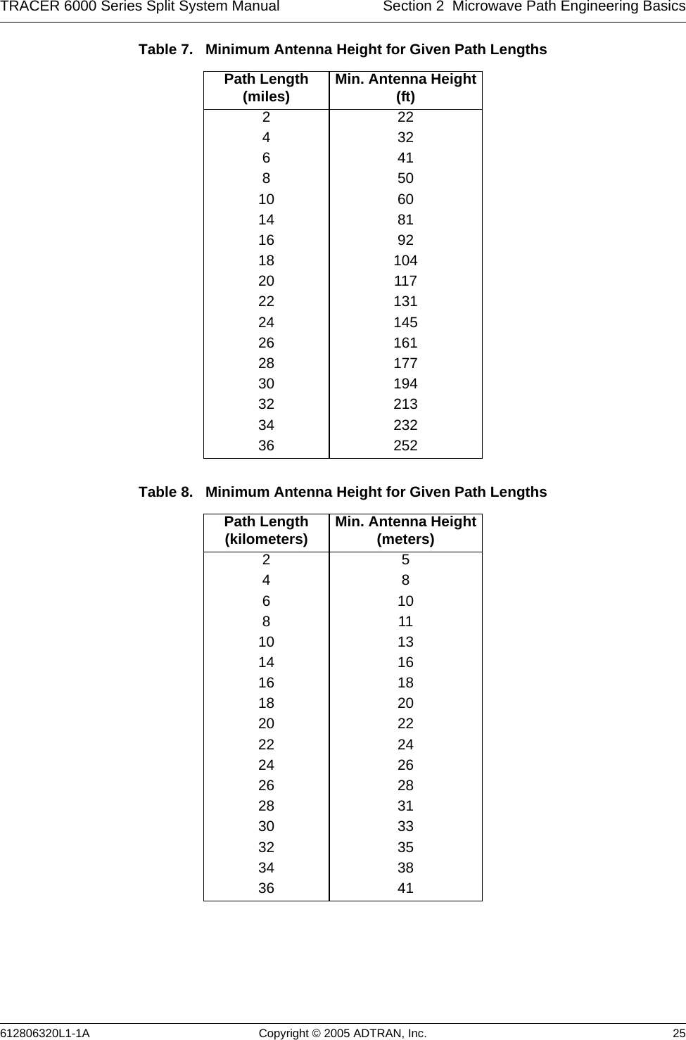
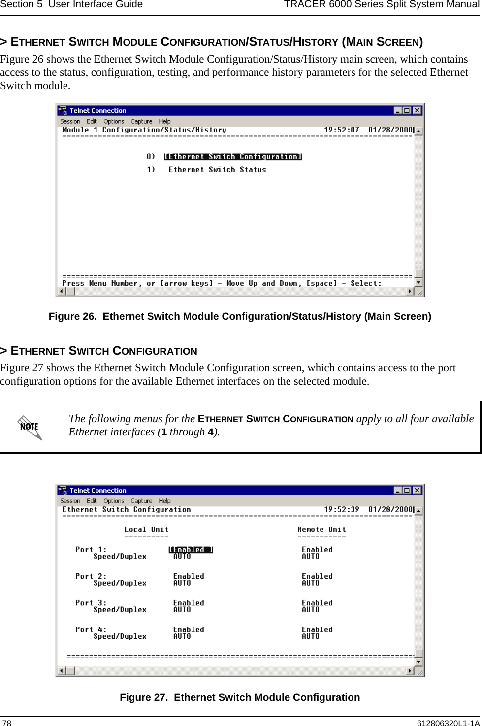
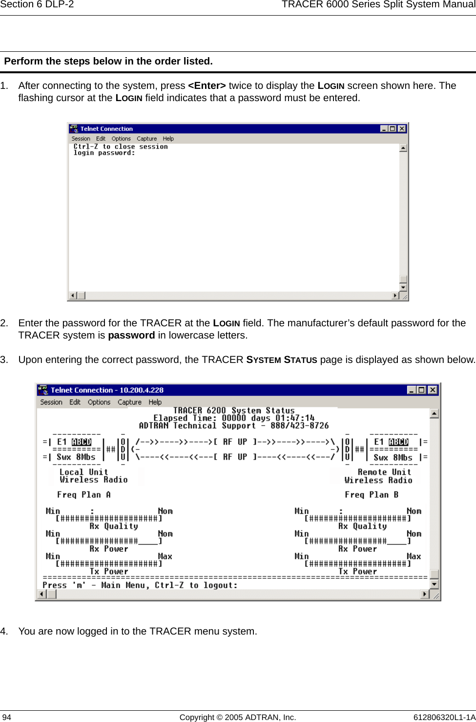
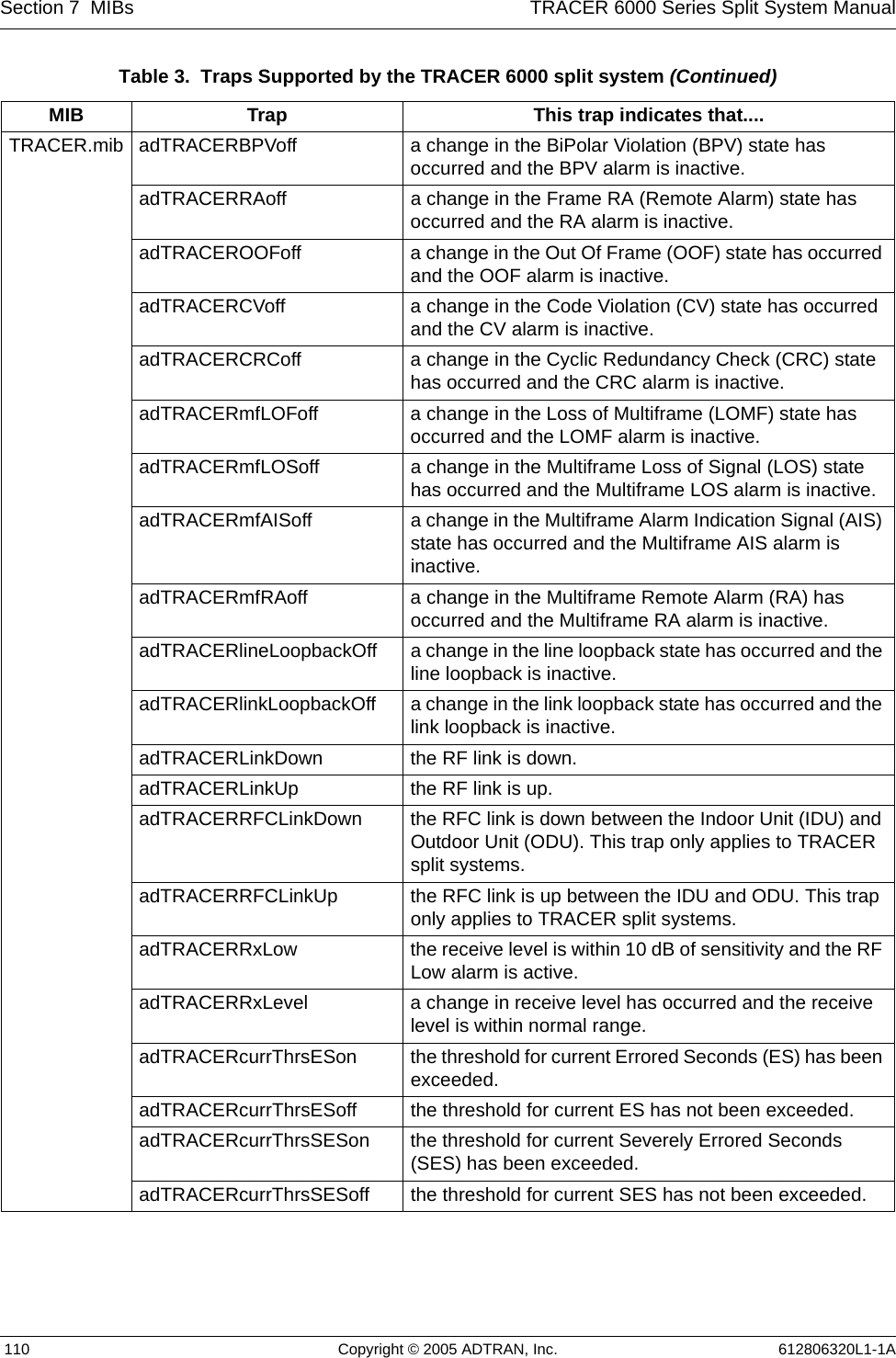
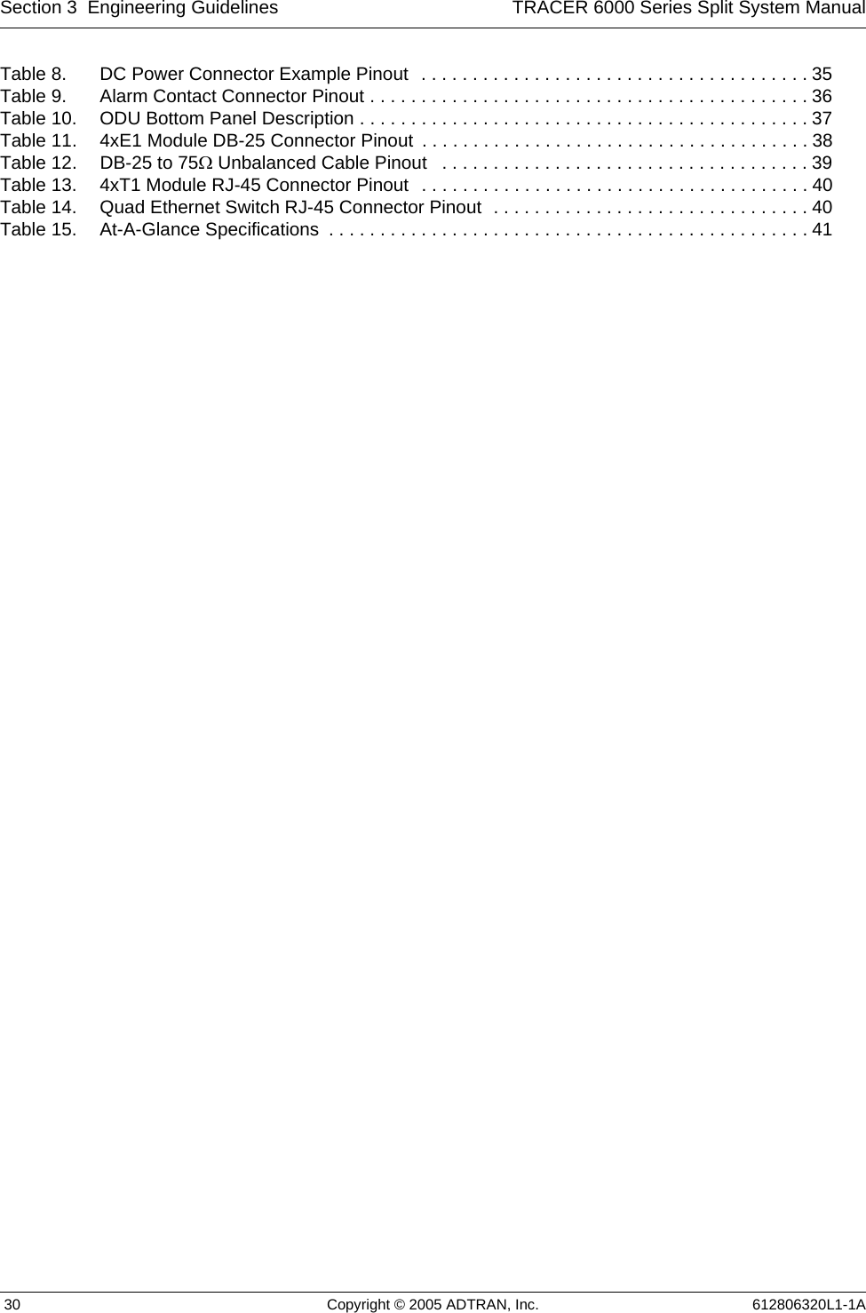
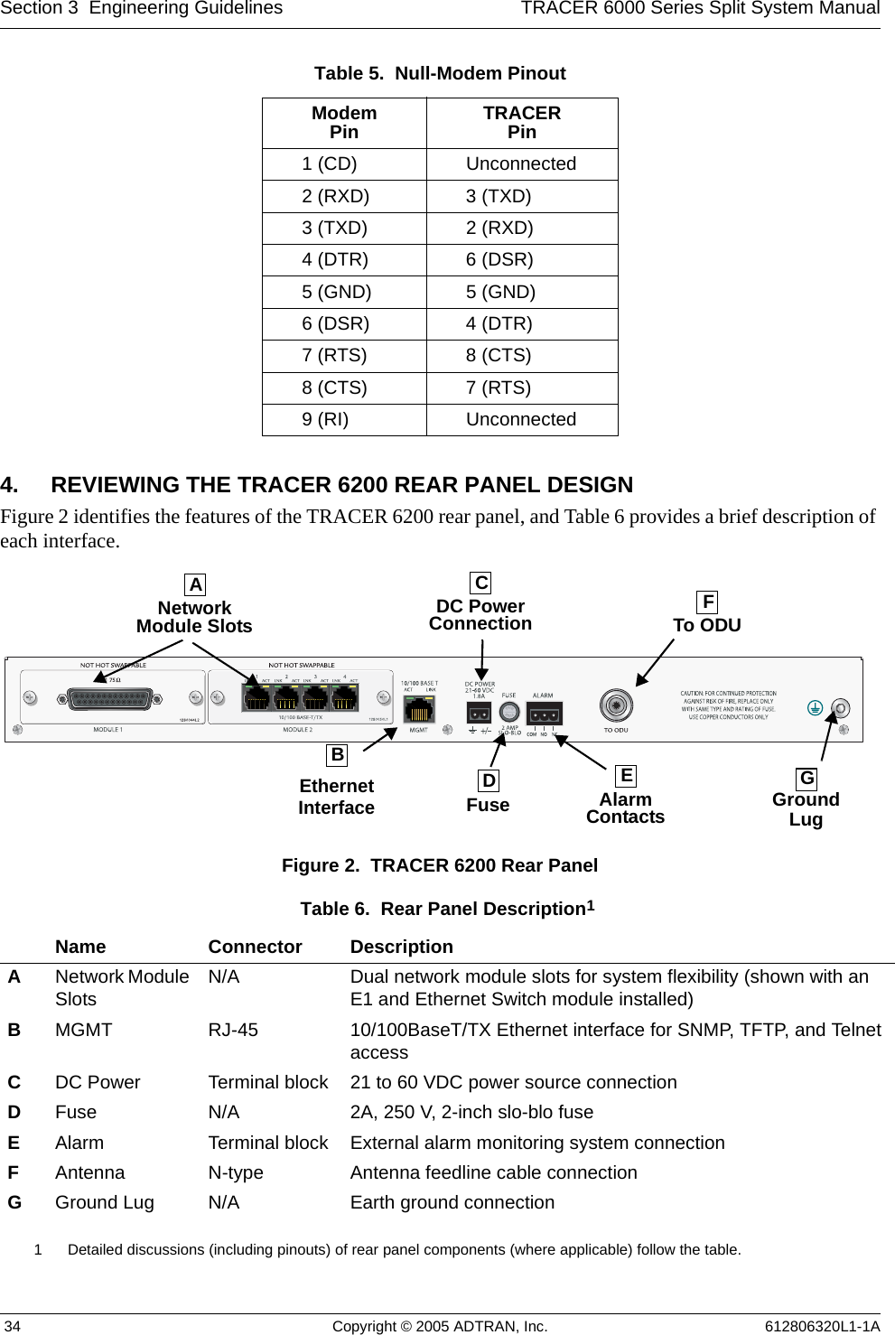
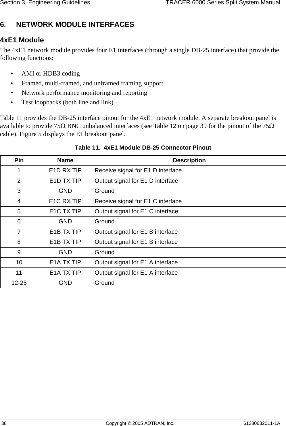
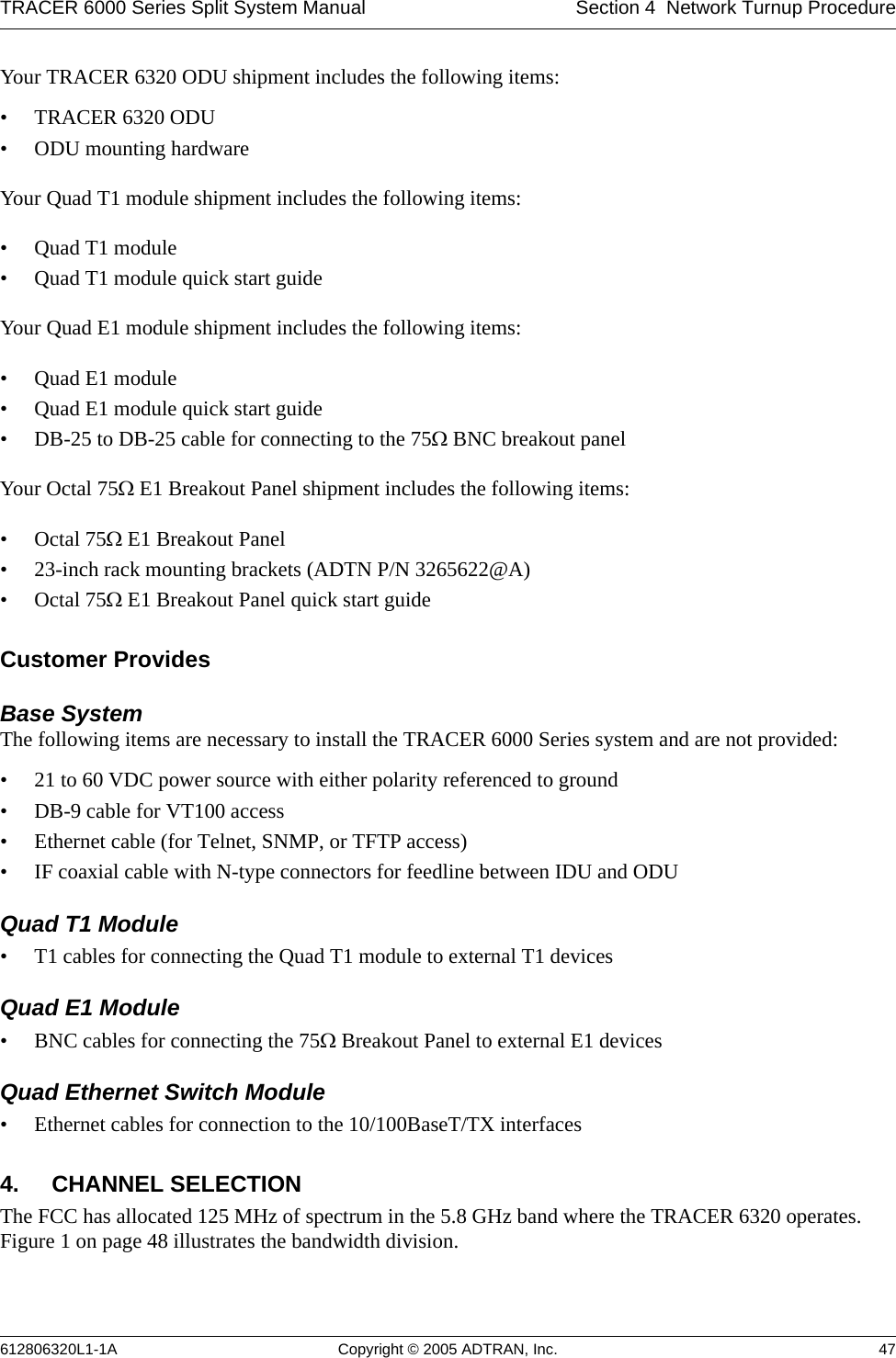
![Section 2 Microwave Path Engineering Basics TRACER 6000 Series Split System Manual 26 Copyright © 2005 ADTRAN, Inc. 612806320L1-1A7. OTHER CONSIDERATIONSPath AvailabilityThe path availability of a wireless link is a metric that expresses the fractional amount of time a link is available over some fixed amount of time, and depends on several factors. Path availability is expressed aswhere the parameters areaterrain factor bclimate factor fcarrier frequency (GHz) dpath length (miles) Ffade margin (dB)orwhere the parameters areaterrain factor bclimate factor fcarrier frequency (GHz) dpath length (kilometers) Ffade margin (dB)Terrain Factor (a)The terrain factor is a quantity that compensates the link availability for different types of terrain. Generally speaking, the smoother an area’s terrain, the less availability a wireless link running over that terrain will have, primarily due to multipath reflections. In contrast, secondary microwave signals will be randomly dispersed over rough terrain and will not interfere with the main signal lobe as badly as in the smooth terrain case. The terrain factor values normally used are listed below:Terrain Terrain Factor DescriptionSmooth 4water, flat desertAverage 1moderate roughnessMountainous 1/4 very rough, mountainousA12.5106–×()abfd310 F10⁄–()–[]100%×=(%)A16.00 10 7–×()abfd310 F10⁄–()–[]100%×=(%)](https://usermanual.wiki/ADTRAN/TRC6320/User-Guide-537882-Page-26.png)
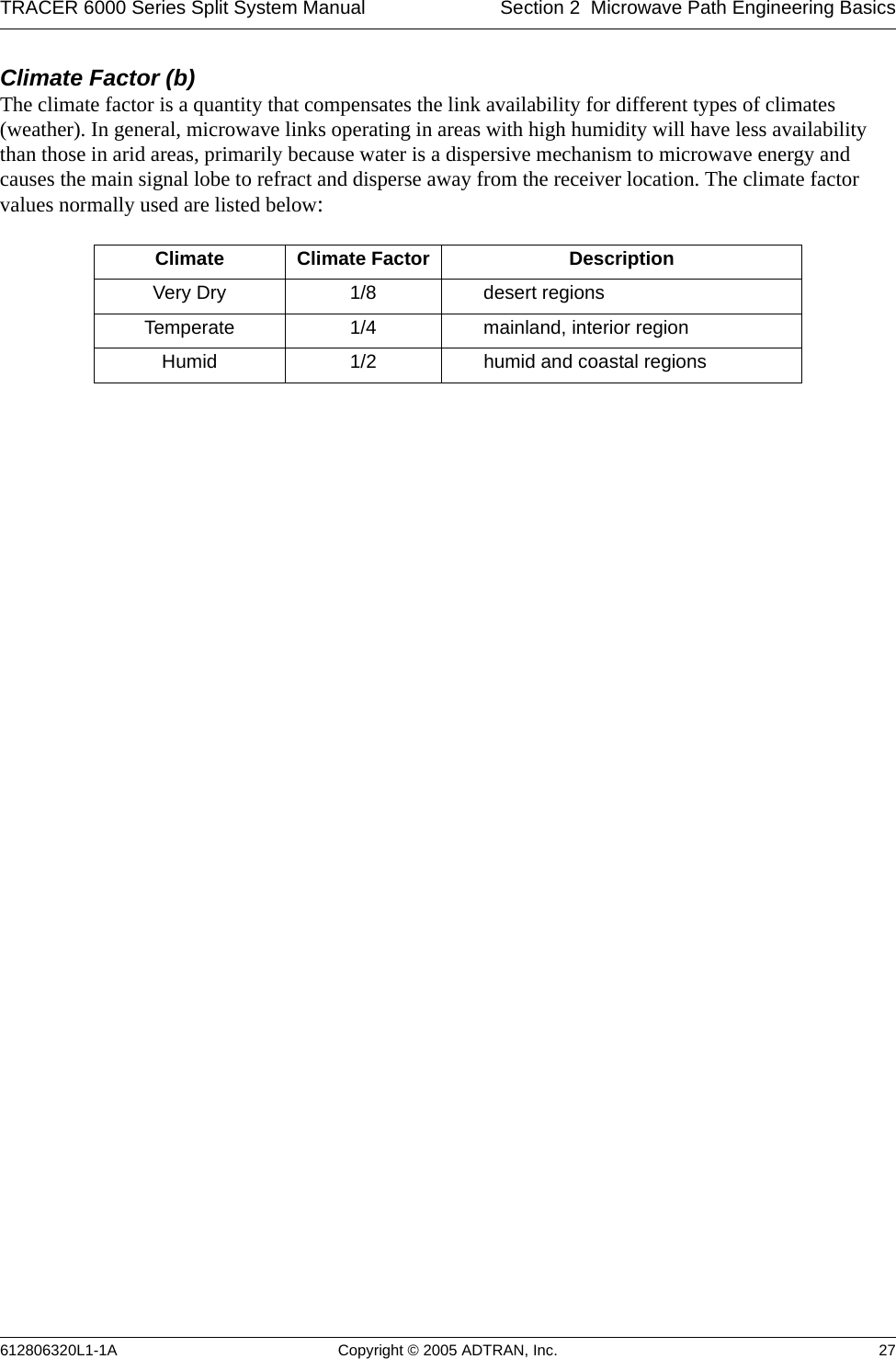
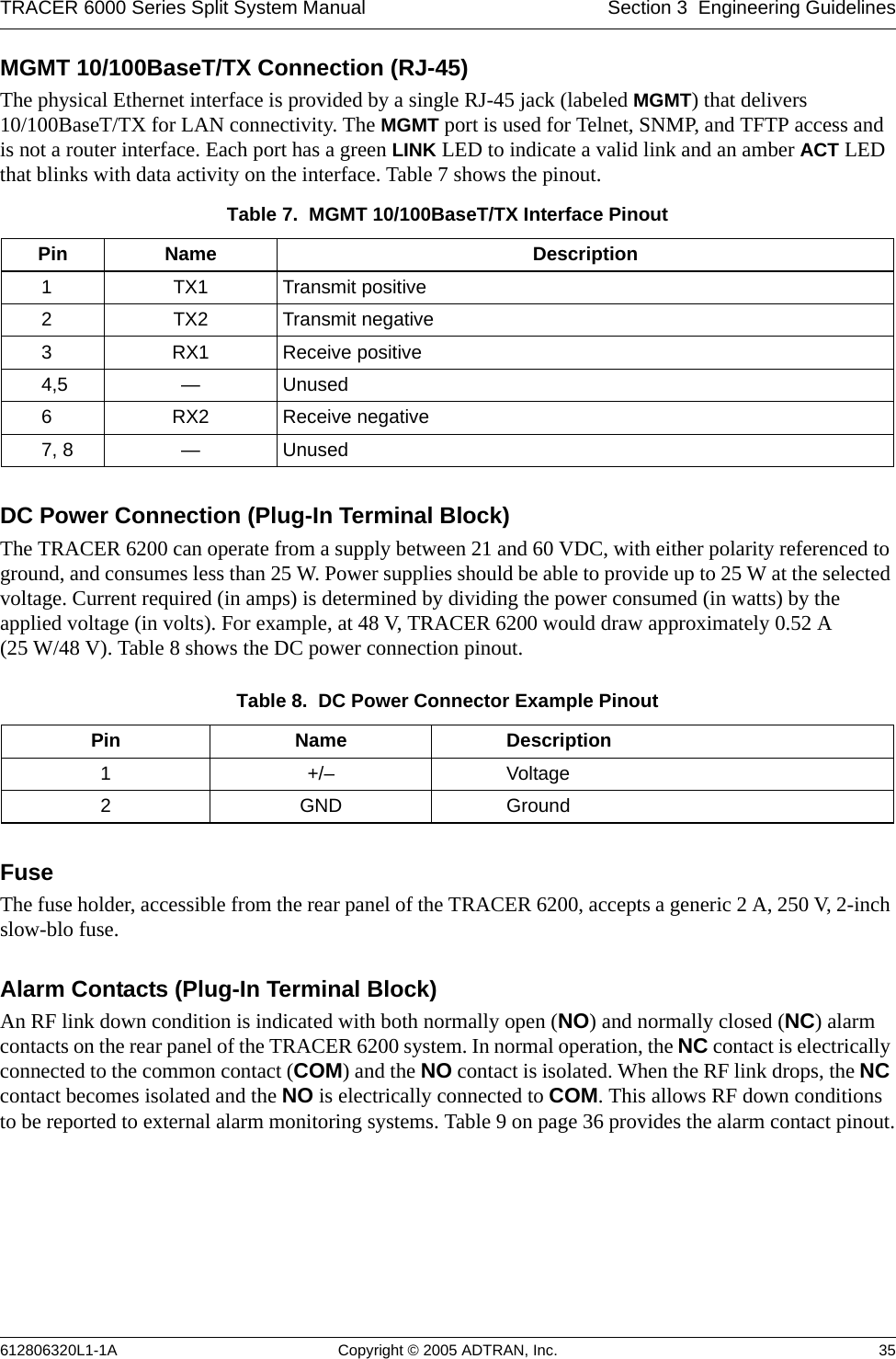
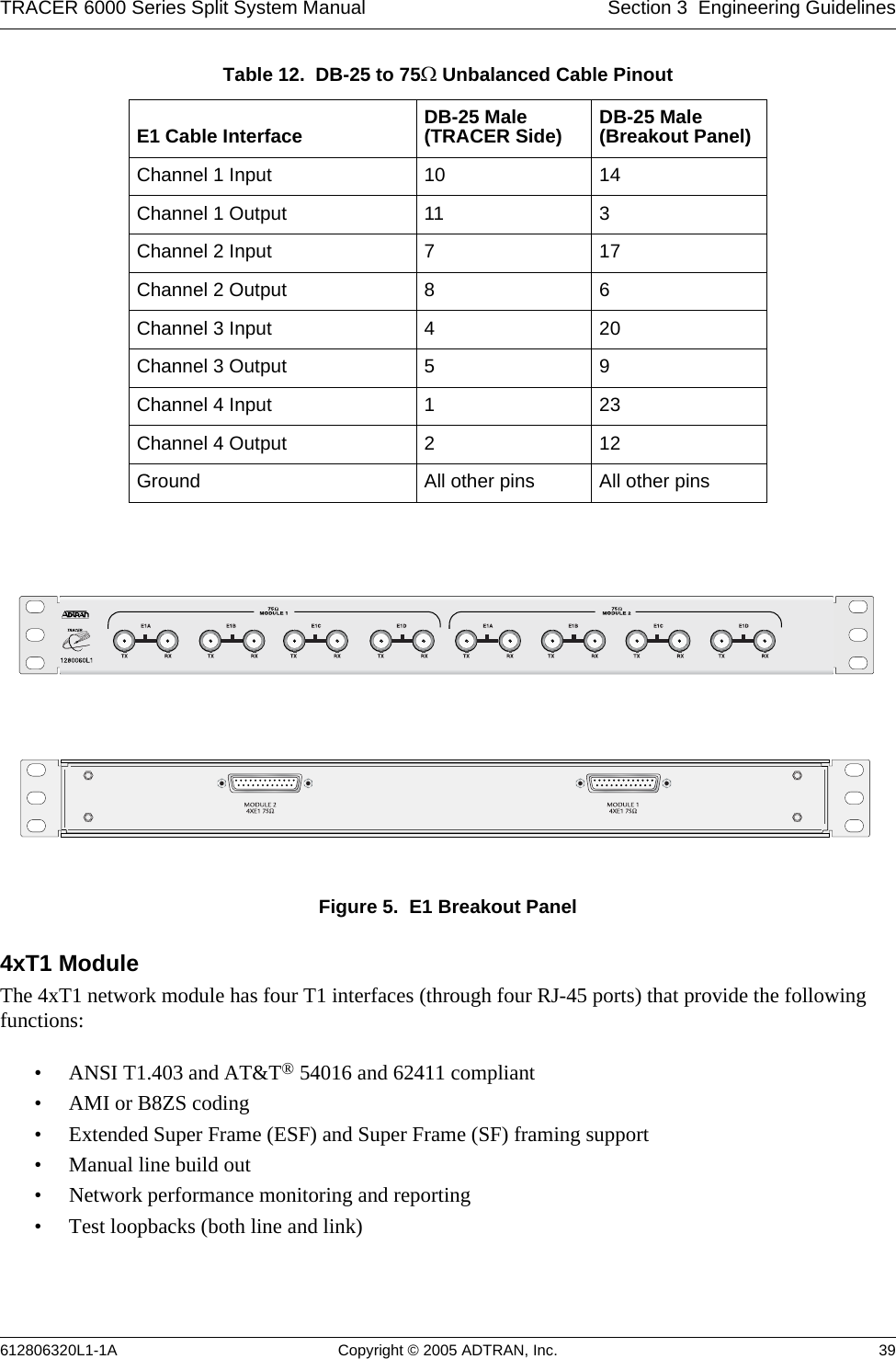

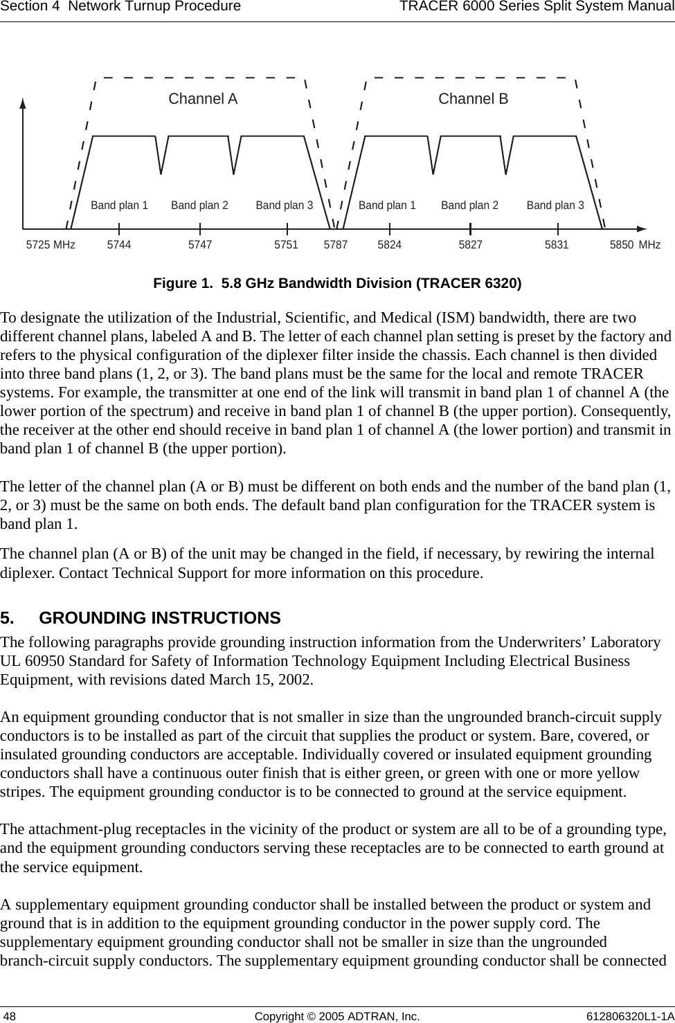
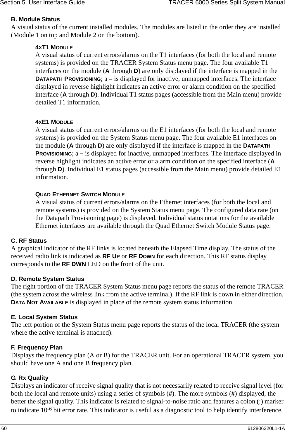
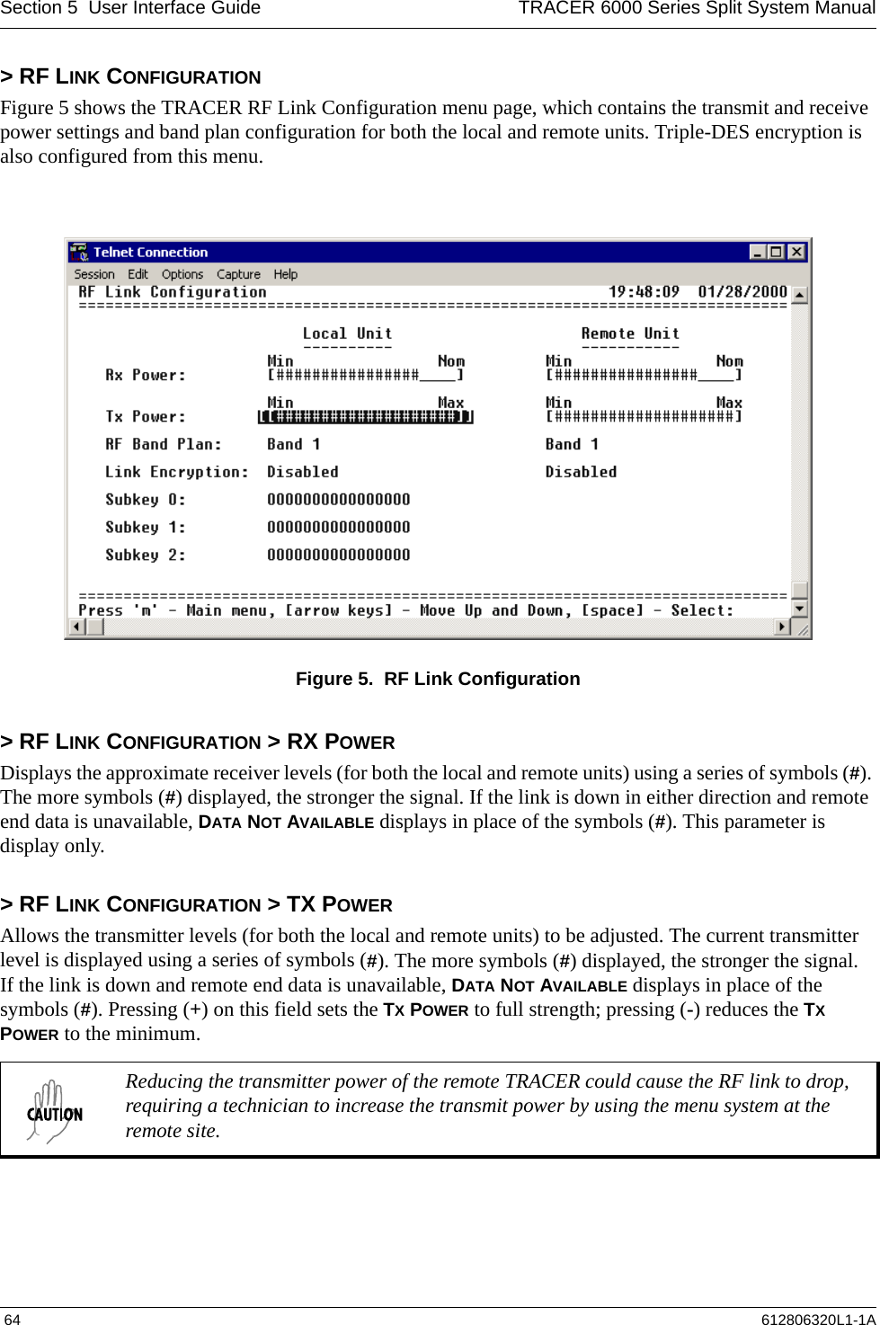
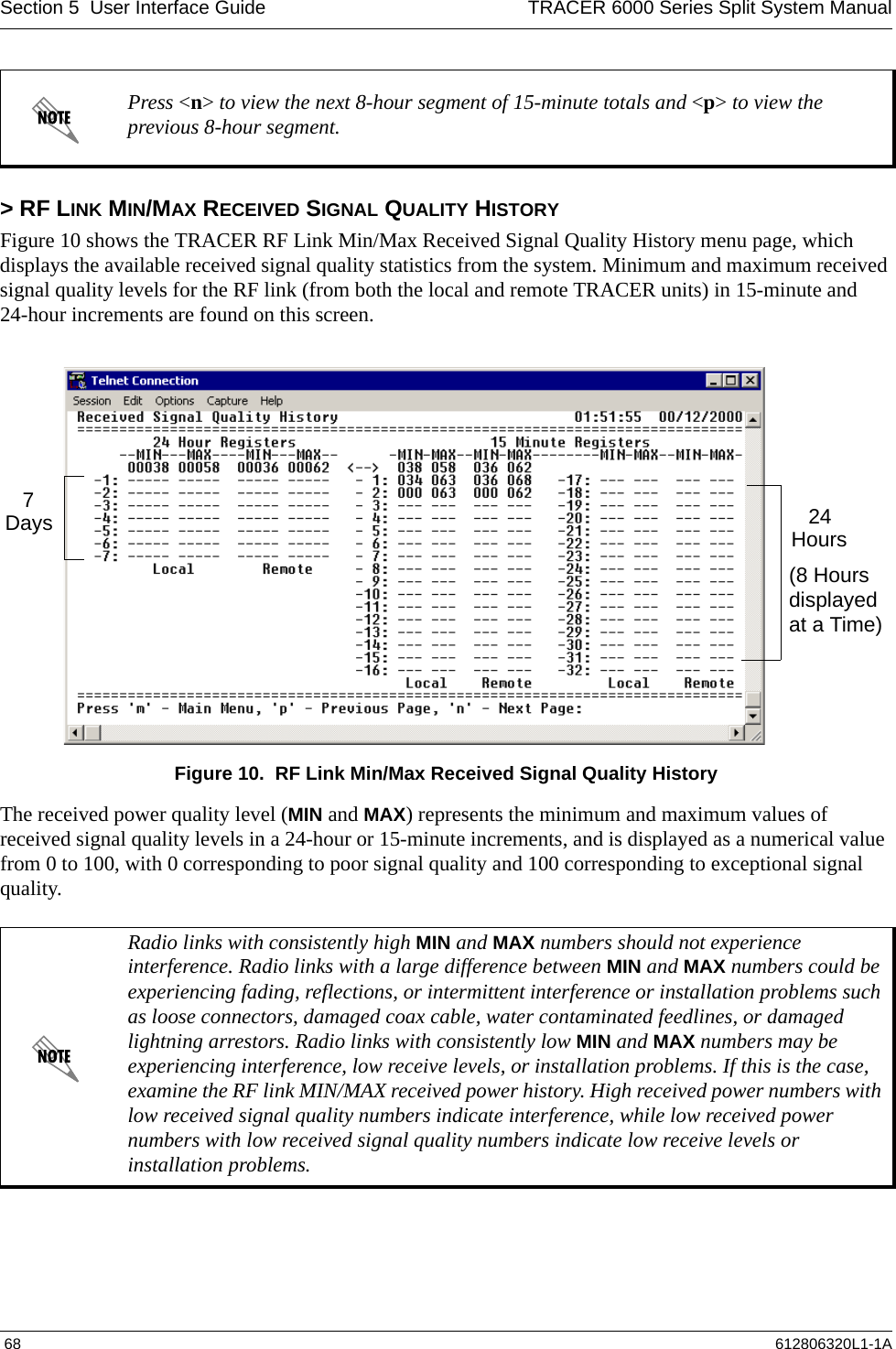
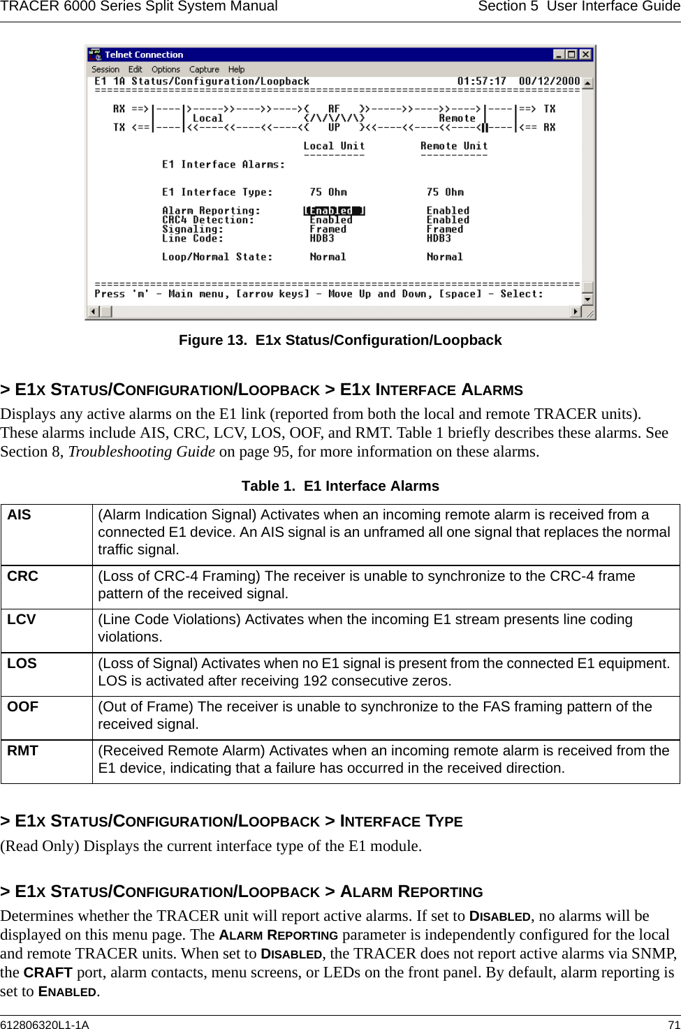
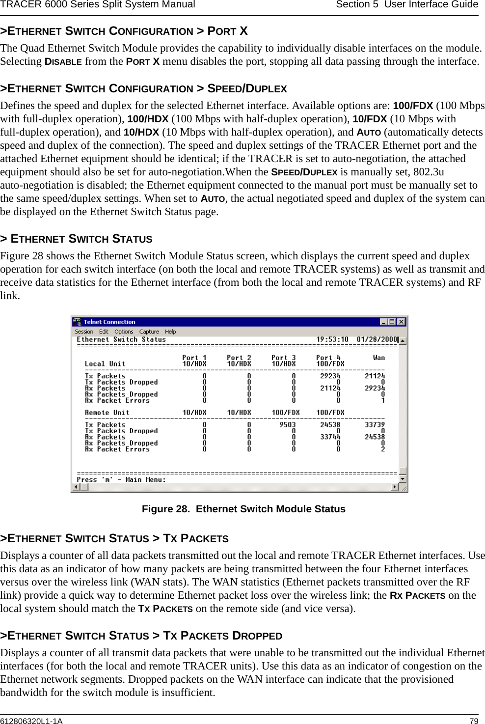
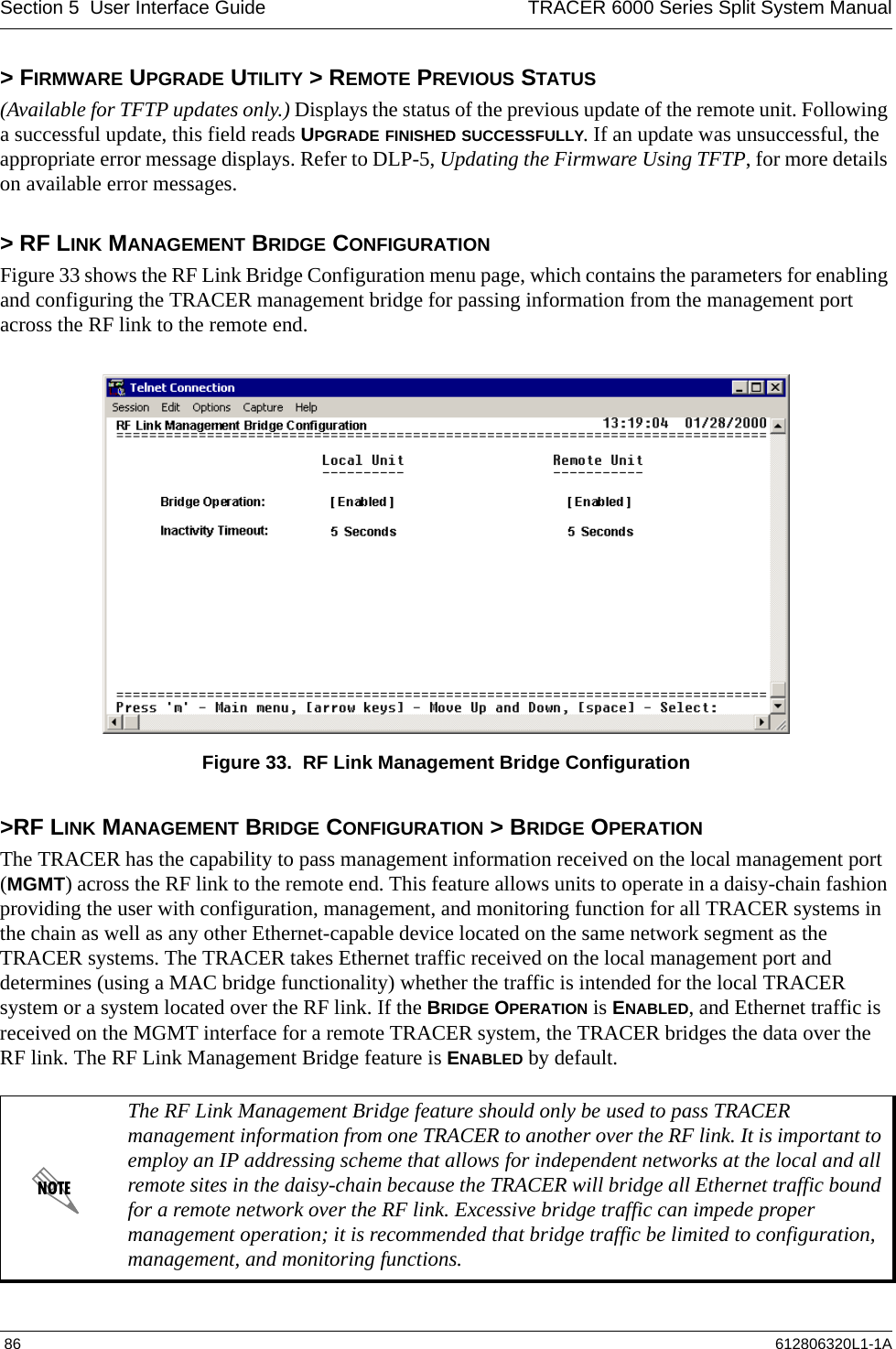
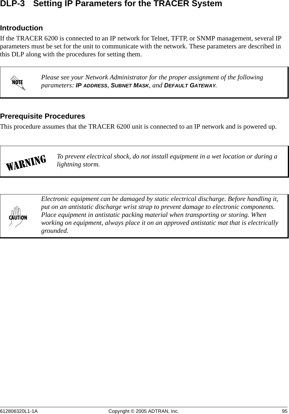
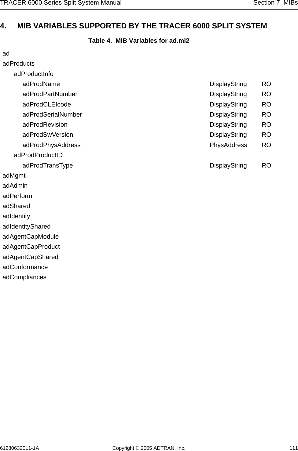
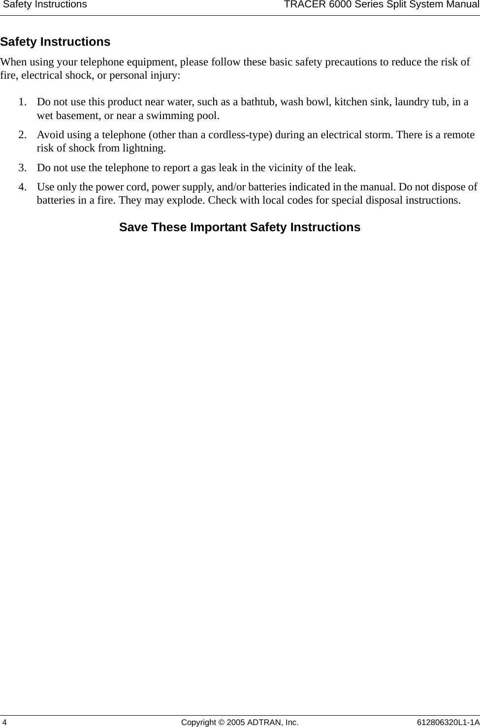
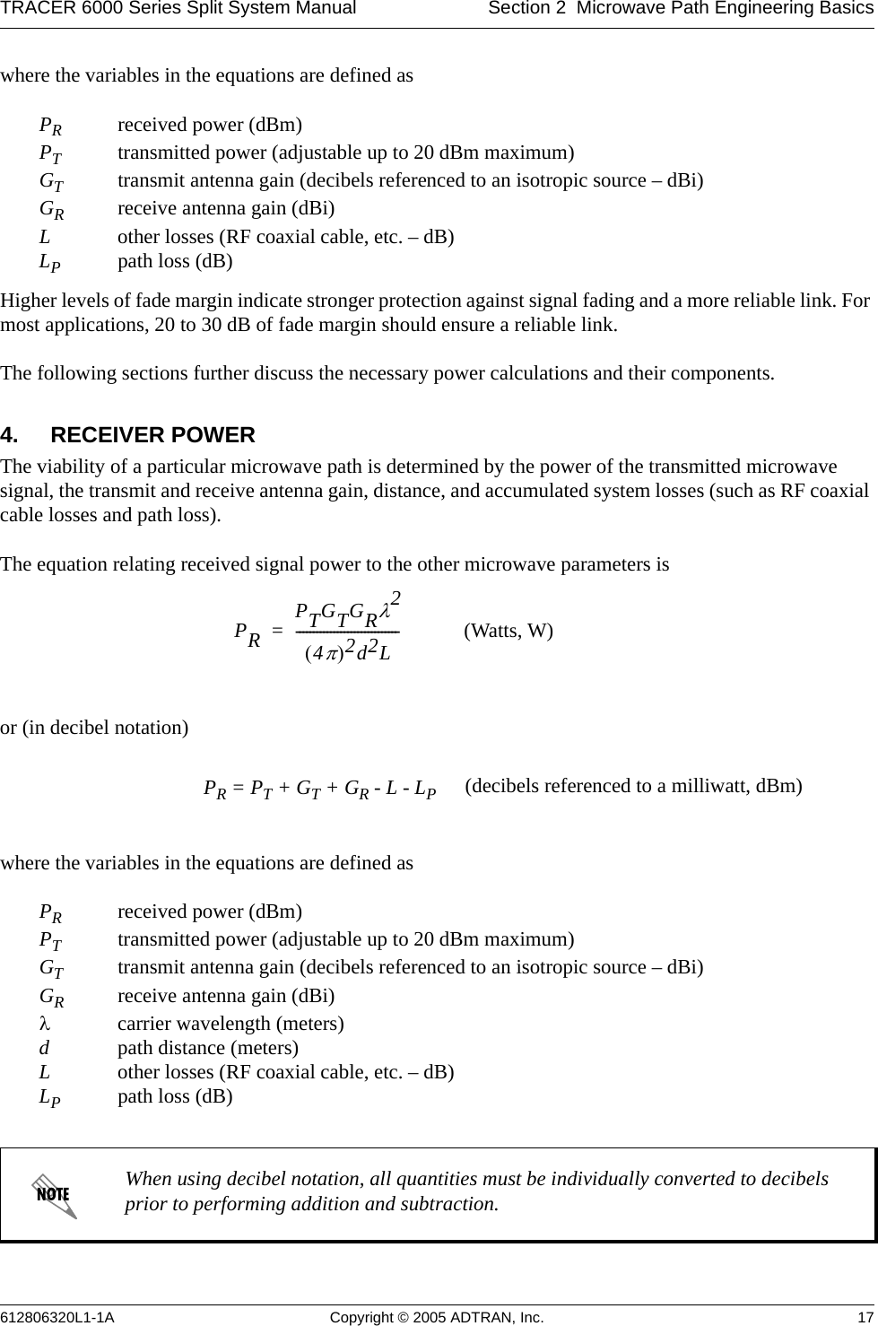
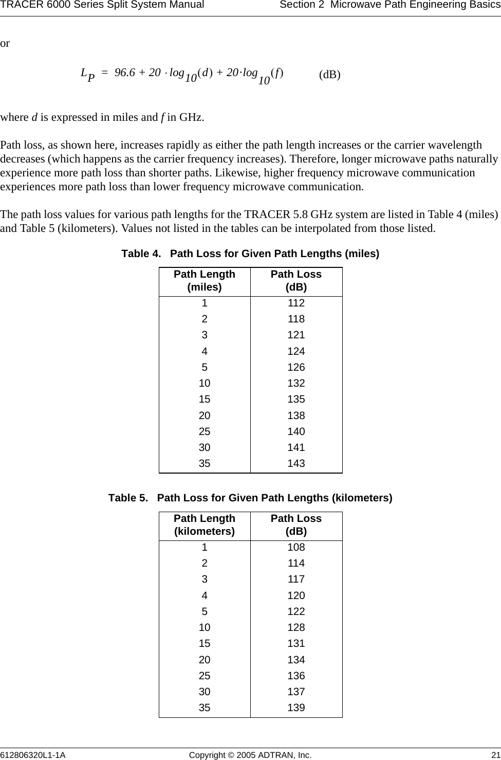
![Section 5 User Interface Guide TRACER 6000 Series Split System Manual 72 612806320L1-1A> E1X STATUS/CONFIGURATION/LOOPBACK > CRC4 DETECTIONWhen ENABLED, the receiver detects the CRC-4 checksum bits in the outgoing E1 data stream and checks the received signal for errors.> E1X STATUS/CONFIGURATION/LOOPBACK > SIGNALINGConfigures the framing format for the E1 link. The TRACER transports E1 data across the link (as long as the E1 signal is properly timed). Configure the framing format (using the SIGNALING menu) to enable the TRACER to monitor incoming framing error events and indicate problems with the attached metallic service. The TRACER supports MULTIFRAMED (also known as CAS), UNFRAMED (all data stream with no framing sequence bits), and FRAMED (also known as CCS). The default value is MULTIFRAMED.> E1X STATUS/CONFIGURATION/LOOPBACK > LINE CODESets the line coding for the E1 link. The TRACER supports high-density bipolar 3 substitution (HDB3) and alternate mark inversion (AMI) line coding. HDB3 coding does not allow more than three consecutive zeros in a transmitted bit stream and is the standard coding method on public networks. > E1X STATUS/CONFIGURATION/LOOPBACK > LOOP/NORMAL STATEControls the loop status of the E1 link. Activates/deactivates loopback conditions for testing purposes.> E1X STATUS/CONFIGURATION/LOOPBACK > LOOP/NORMAL STATE > NORMALDefines the E1 link as normal data transport mode; there are no active loopbacks.> E1X STATUS/CONFIGURATION/LOOPBACK > LOOP/NORMAL STATE > LINK [LOCAL]Activates a loopback at the local TRACER E1 framer towards the remote end of the wireless link (see Figure 14). Use the local LINK loopback to loop the data transmitted from the remote end of the link back across the radio link to the remote end of the link. This loopback tests the integrity of the radio link and all the associated digital and RF hardware.Figure 14. E1 Local Link Loopback> E1X STATUS/CONFIGURATION/LOOPBACK > LOOP/NORMAL STATE > LINK [REMOTE]Activates a loopback at the remote TRACER E1 framer towards the local end of the wireless link (see Figure 15). Use the remote LINK loopback to loop the data transmitted from the local end of the link across the radio link to the local end of the link. This loopback tests the integrity of the radio link and all the associated digital and RF hardware.Figure 15. E1 Remote Link Loopback](https://usermanual.wiki/ADTRAN/TRC6320/User-Guide-537882-Page-72.png)
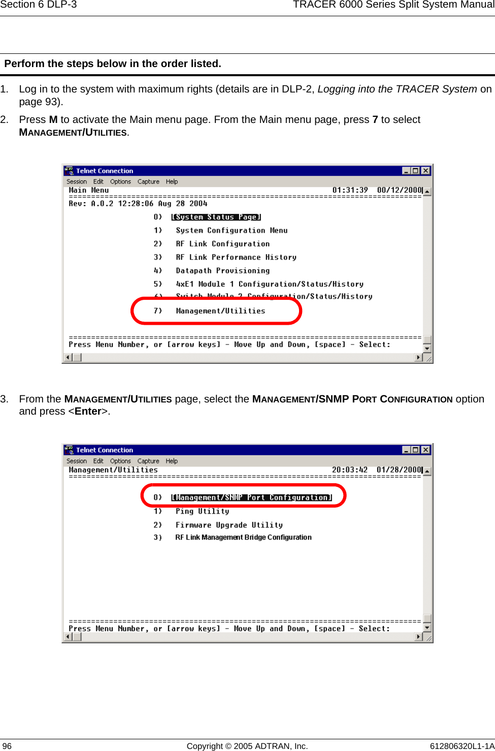
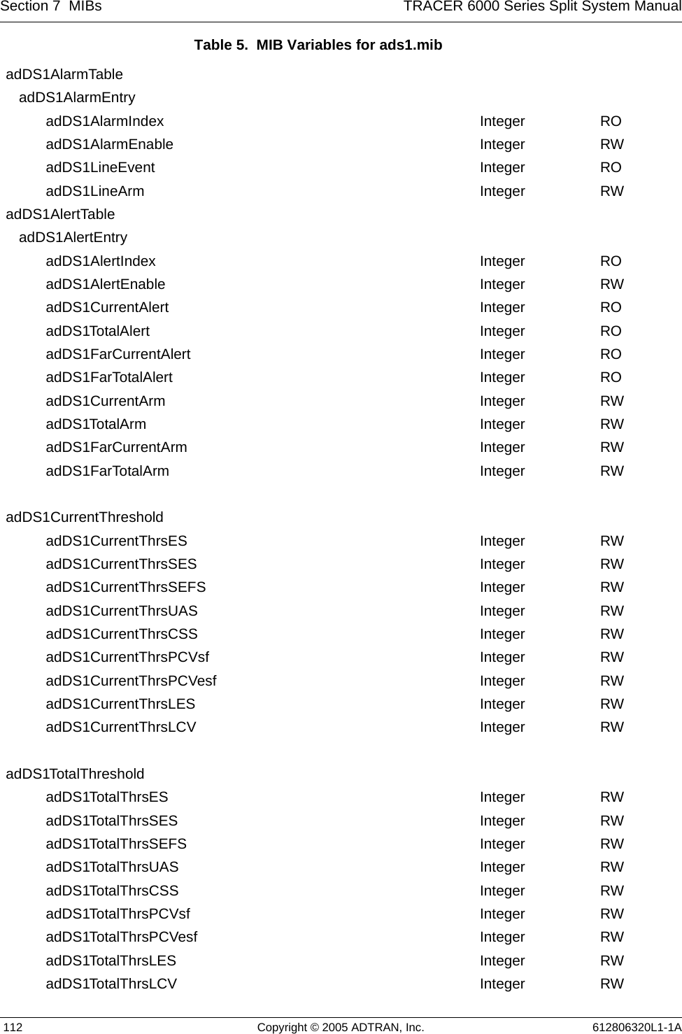
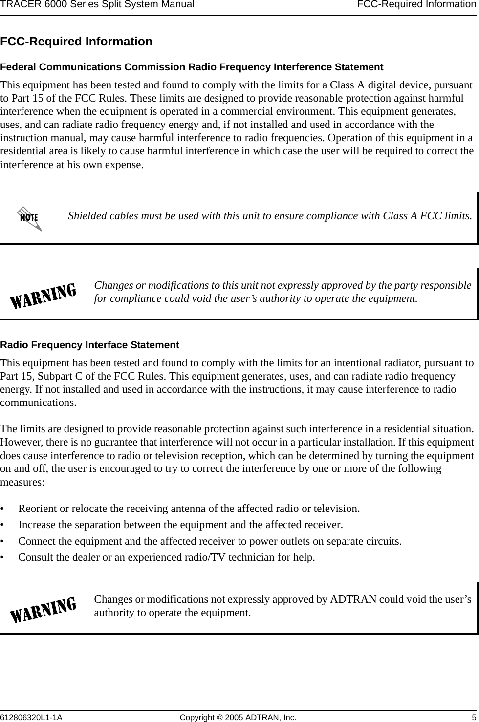
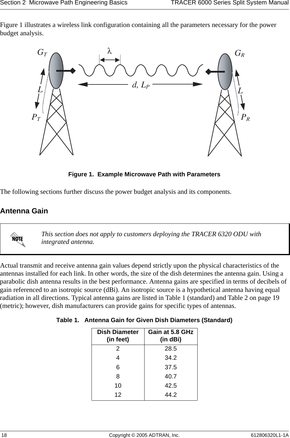
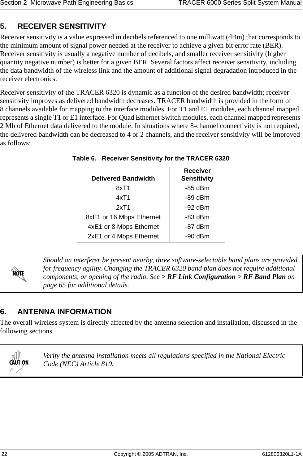
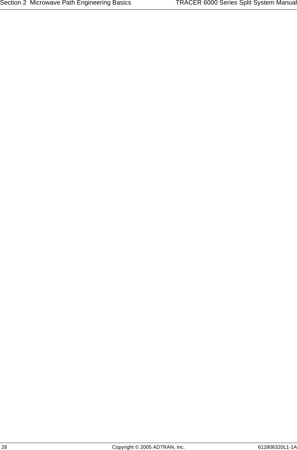
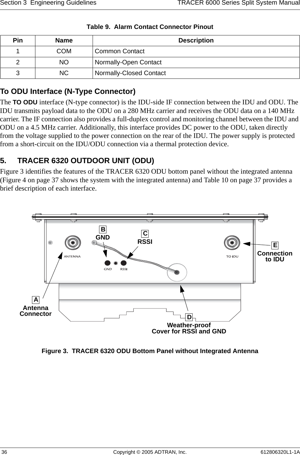
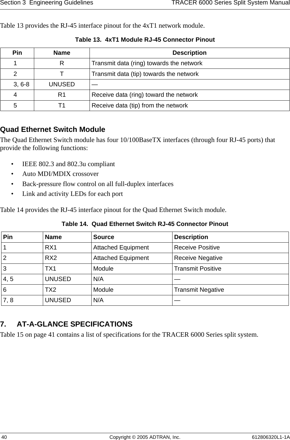
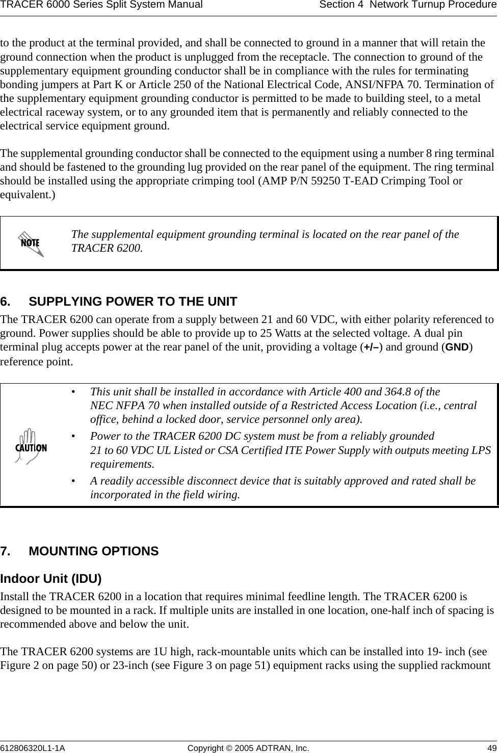
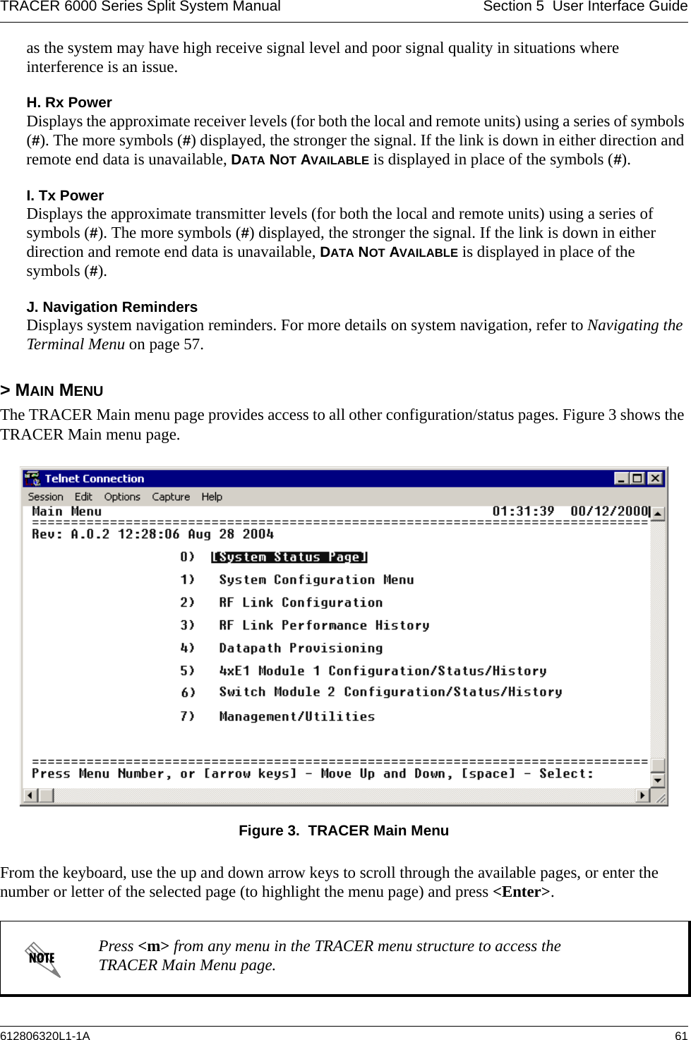
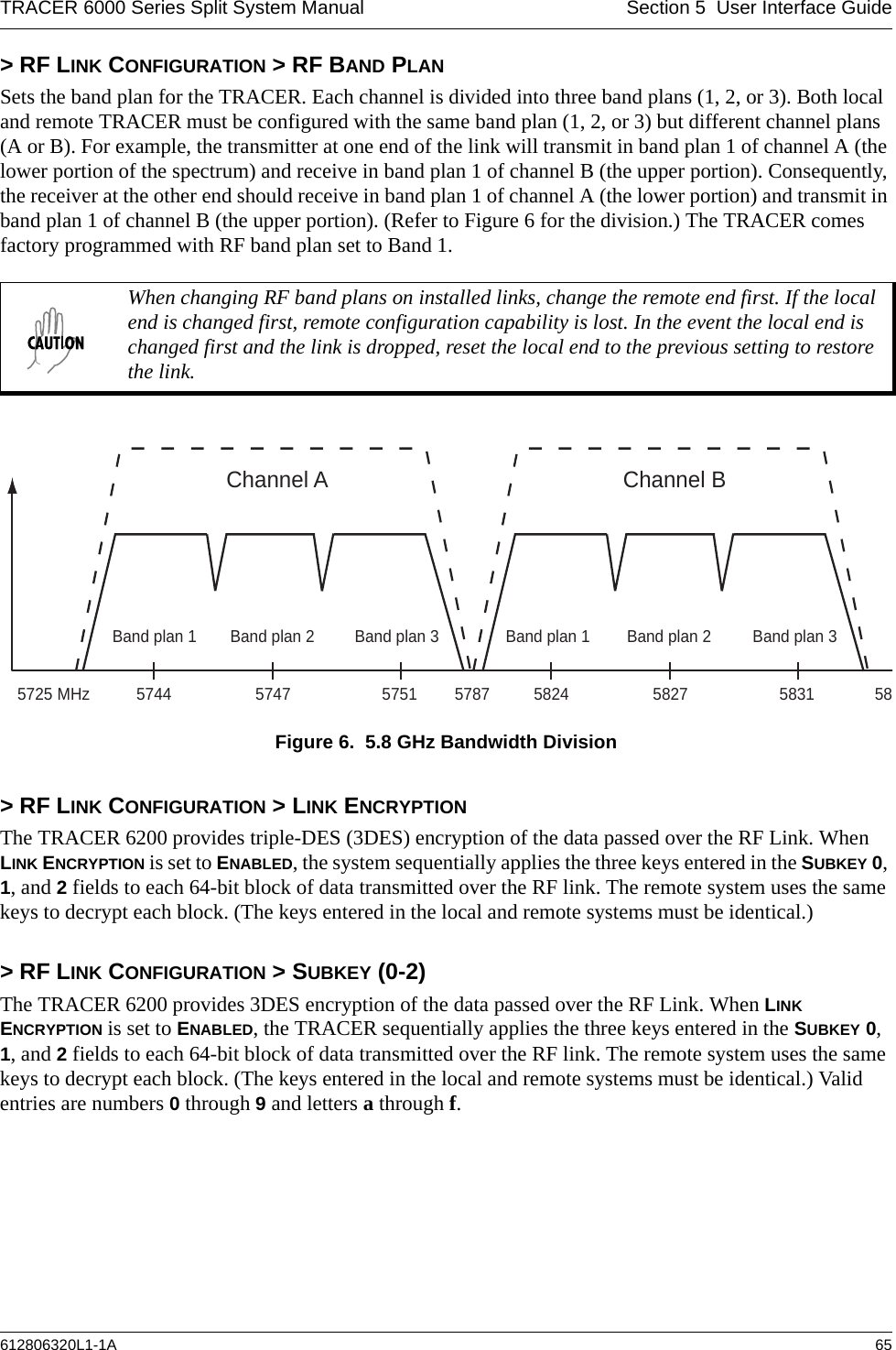
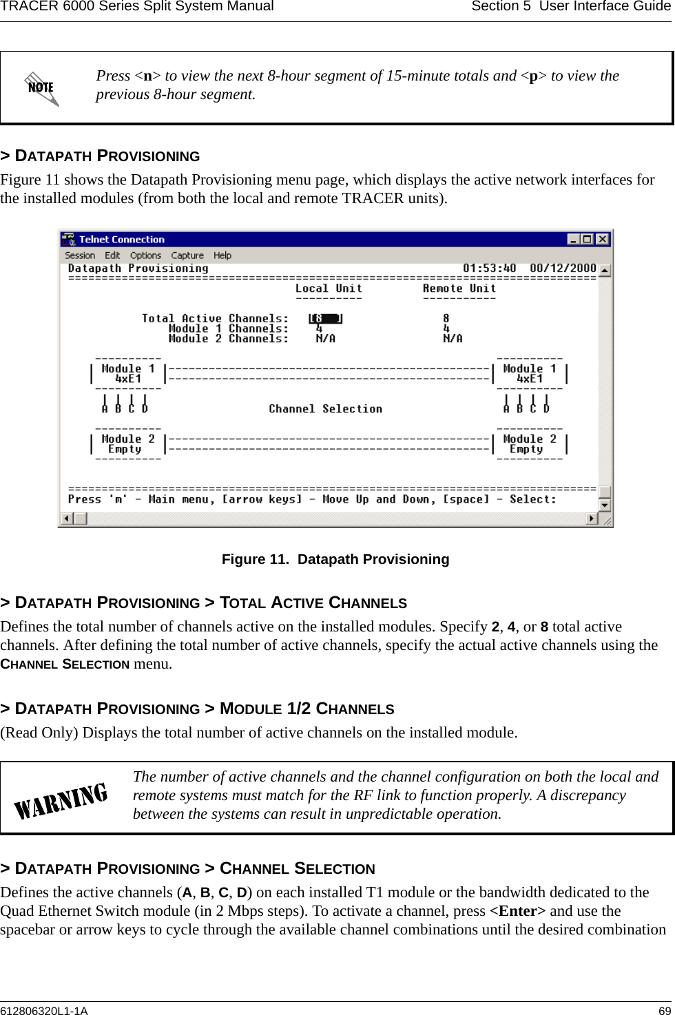
![TRACER 6000 Series Split System Manual Section 5 User Interface Guide612806320L1-1A 73> E1X STATUS/CONFIGURATION/LOOPBACK > LOOP/NORMAL STATE > LINE [LOCAL]Activates a loopback at the local TRACER E1 framer towards the locally connected E1 equipment (see Figure 16). Use the local LINE loopback to test data path integrity from the local TRACER unit to the connected E1 equipment.Figure 16. E1 Local Line Loopback> E1X STATUS/CONFIGURATION/LOOPBACK > LOOP/NORMAL STATE > LINE [REMOTE]Activates a loopback at the remote TRACER E1 framer towards the connected E1 equipment at the remote end of the link (see Figure 17). Use the remote LINE loopback to test data path integrity from the remote TRACER unit to the E1 equipment connected at the remote end of the link.Figure 17. E1 Remote Line Loopback> E1X PERFORMANCE HISTORYFigure 18 shows the E1x Performance History menu page, which displays detailed error statistics for the E1 link (from both the local and remote TRACER units) in 15-minute and 24-hour increments. Figure 18. E1x Link Performance HistoryThe following menus for the E1x Performance History apply to all four available E1 interfaces (A through D).7 Days24Hours(8 Hoursdisplayedat a time)](https://usermanual.wiki/ADTRAN/TRC6320/User-Guide-537882-Page-73.png)
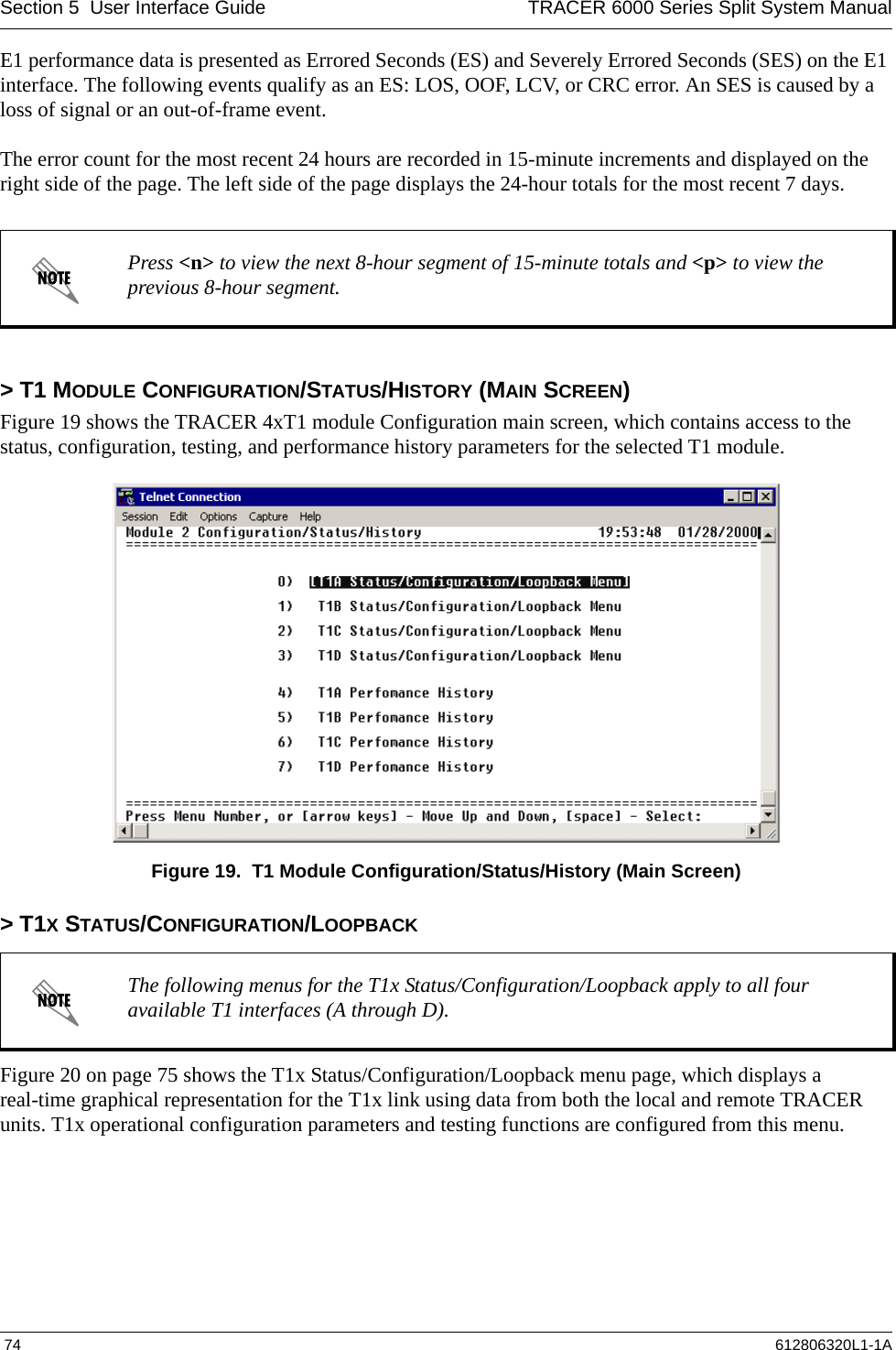
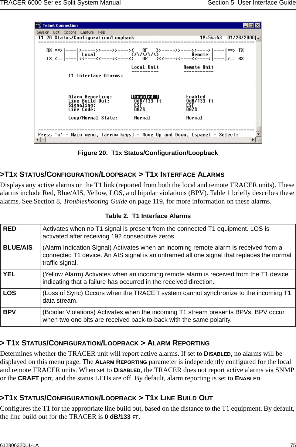
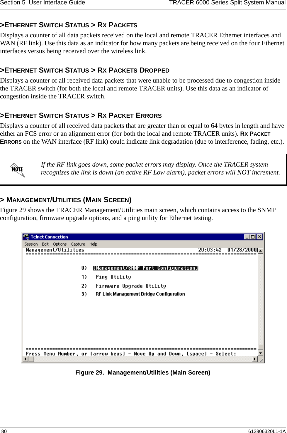
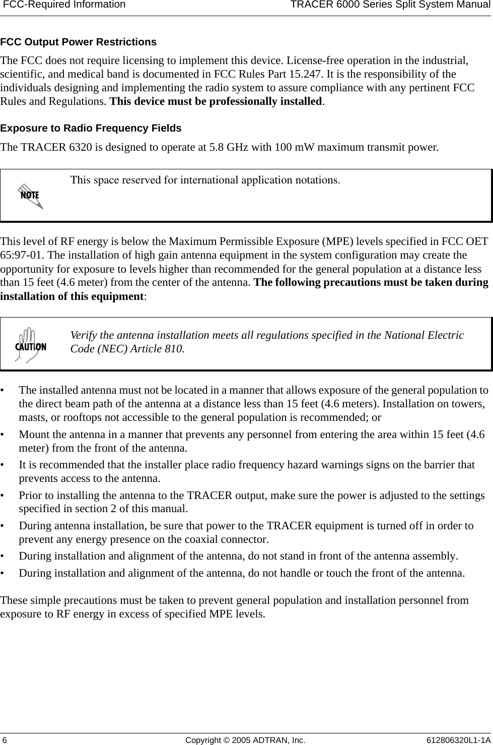
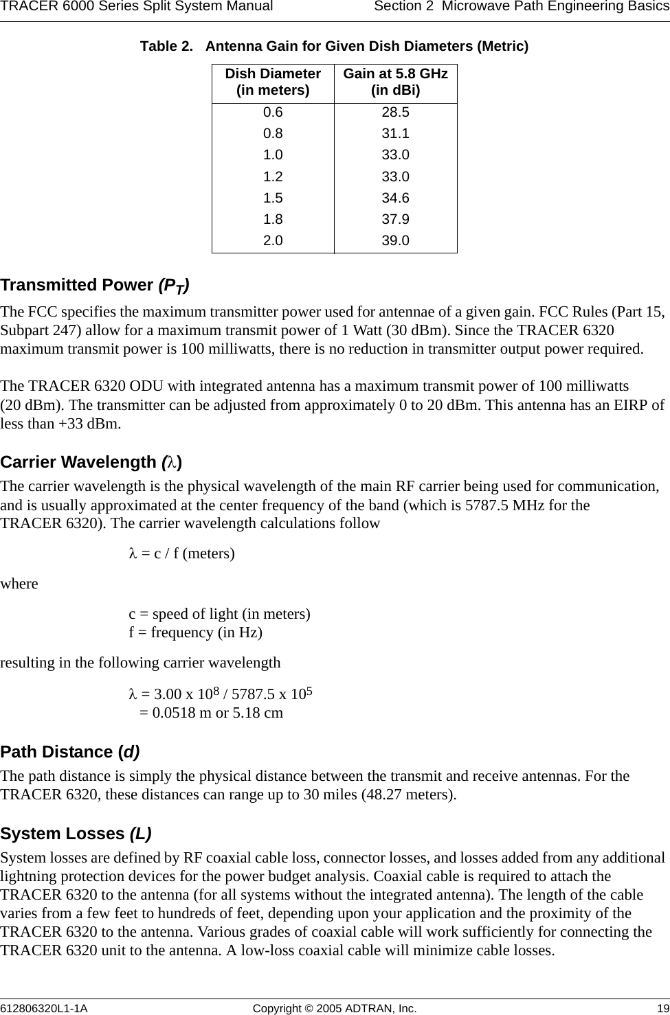
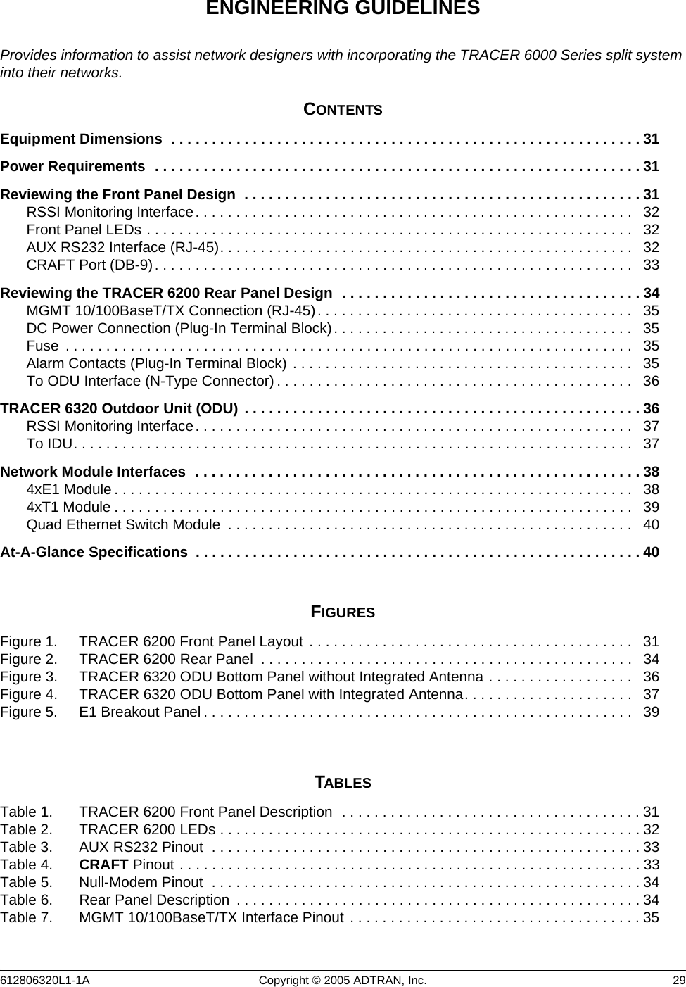
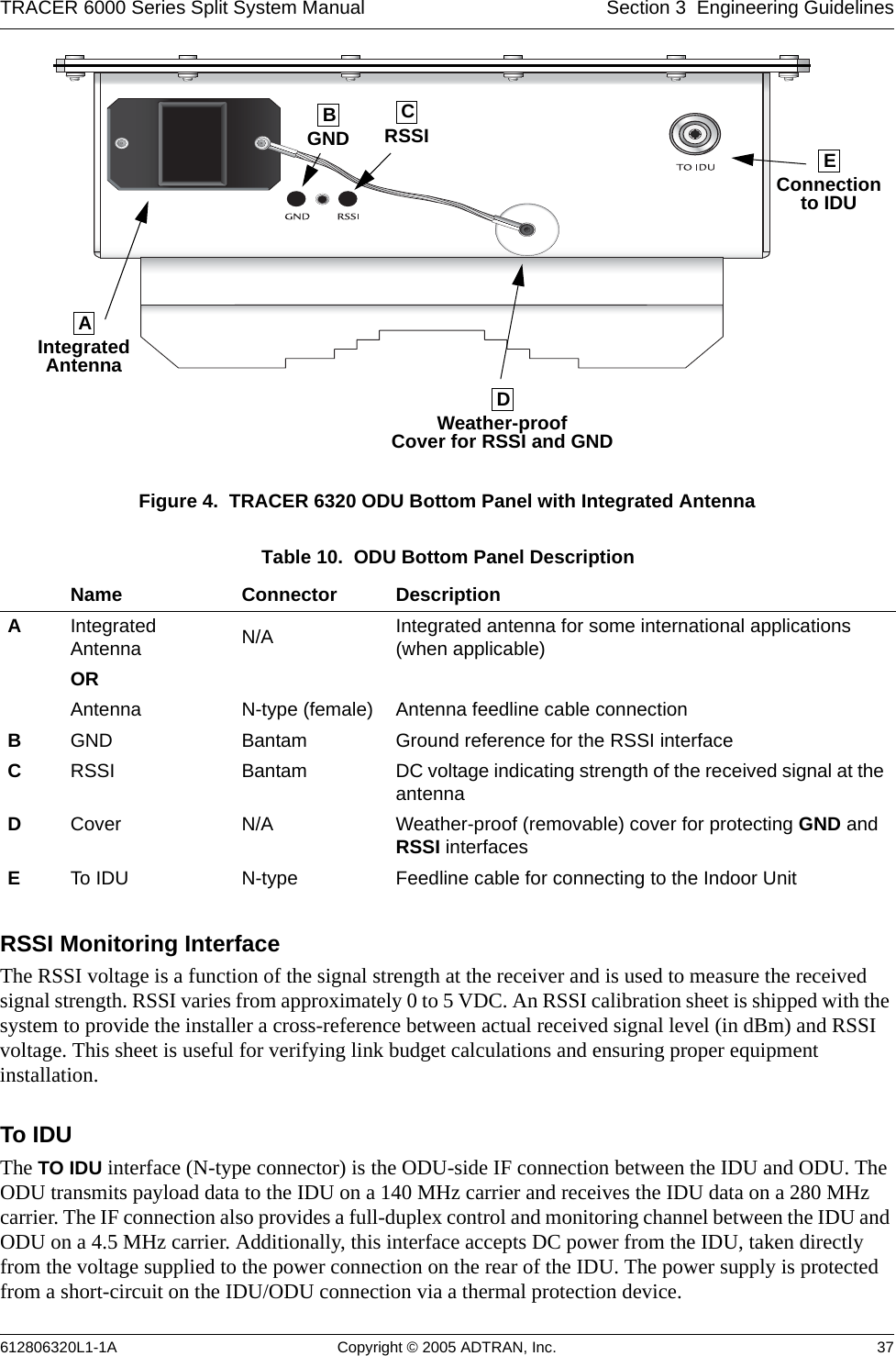
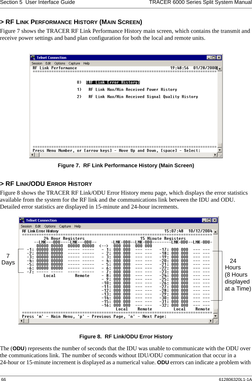
![Section 5 User Interface Guide TRACER 6000 Series Split System Manual 76 612806320L1-1A> T1X STATUS/CONFIGURATION/LOOPBACK > SIGNALINGConfigures the framing format for the T1 link for both the local and remote TRACER units. The TRACER transports T1 data across the link (as long as the T1 signal is properly timed). Configure the framing format (using the SIGNALING menu) to enable the TRACER to monitor incoming framing error events and indicate problems with the attached metallic service. The TRACER supports both extended superframe (ESF) and superframe (D4) framing formats. By default, the signaling method is set to ESF.> T1X STATUS/CONFIGURATION/LOOPBACK > LINE CODESets the line coding for the T1 link. The TRACER supports bipolar eight-zero substitution (B8ZS) and alternate mark inversion (AMI) line coding. By default, the line code is set to B8ZS.> T1X STATUS/CONFIGURATION/LOOPBACK > LOOP/NORMAL STATEControls the loop status of the T1 link. Activates/deactivates loopback conditions for testing purposes.> T1X STATUS/CONFIGURATION/LOOPBACK > LOOP/NORMAL STATE > NORMALDefines the T1 link as normal data transport mode; there are no active loopbacks.> T1X STATUS/CONFIGURATION/LOOPBACK > LOOP/NORMAL STATE > LINK [LOCAL]Activates a loopback at the local TRACER T1 framer towards the remote end of the wireless link (see Figure 14). Use the local LINK loopback to loop the data transmitted from the remote end of the link back across the radio link to the remote end of the link. This loopback tests the integrity of the radio link and all the associated digital and RF hardware.Figure 21. T1 Local Link Loopback> T1X STATUS/CONFIGURATION/LOOPBACK > LOOP/NORMAL STATE > LINK [REMOTE]Activates a loopback at the remote TRACER T1 framer towards the local end of the wireless link (see Figure 15). Use the remote LINK loopback to loop the data transmitted from the local end of the link across the radio link to the local end of the link. This loopback tests the integrity of the radio link and all the associated digital and RF hardware.Figure 22. T1 Remote Link Loopback> T1X STATUS/CONFIGURATION/LOOPBACK > LOOP/NORMAL STATE > LINE [LOCAL]Activates a loopback at the local TRACER T1 framer towards the connected T1 equipment (see Figure 23). Use the local LINE loopback to test data path integrity from the local TRACER unit to the connected T1 equipment.Figure 23. T1 Local Line Loopback](https://usermanual.wiki/ADTRAN/TRC6320/User-Guide-537882-Page-76.png)
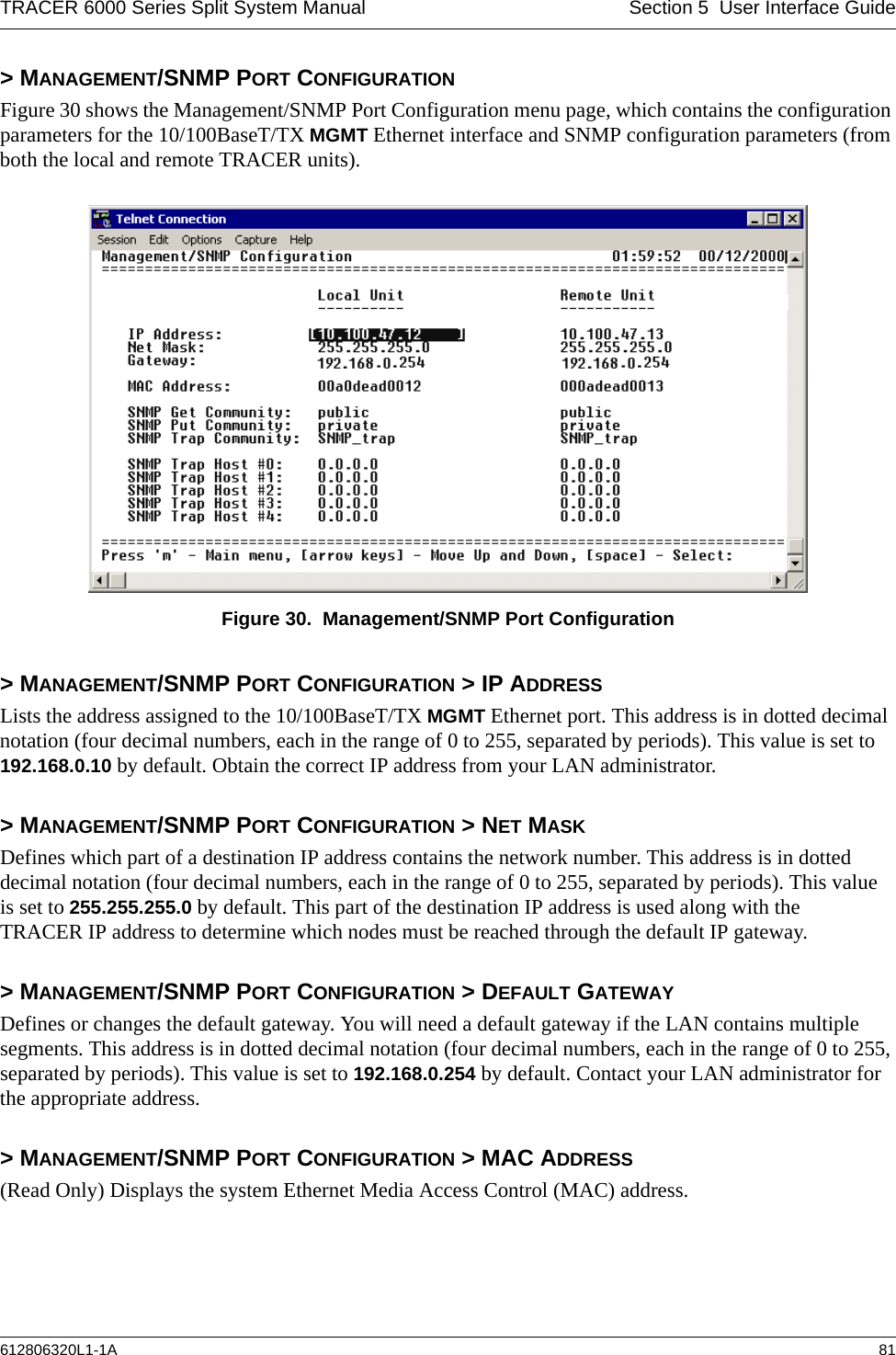
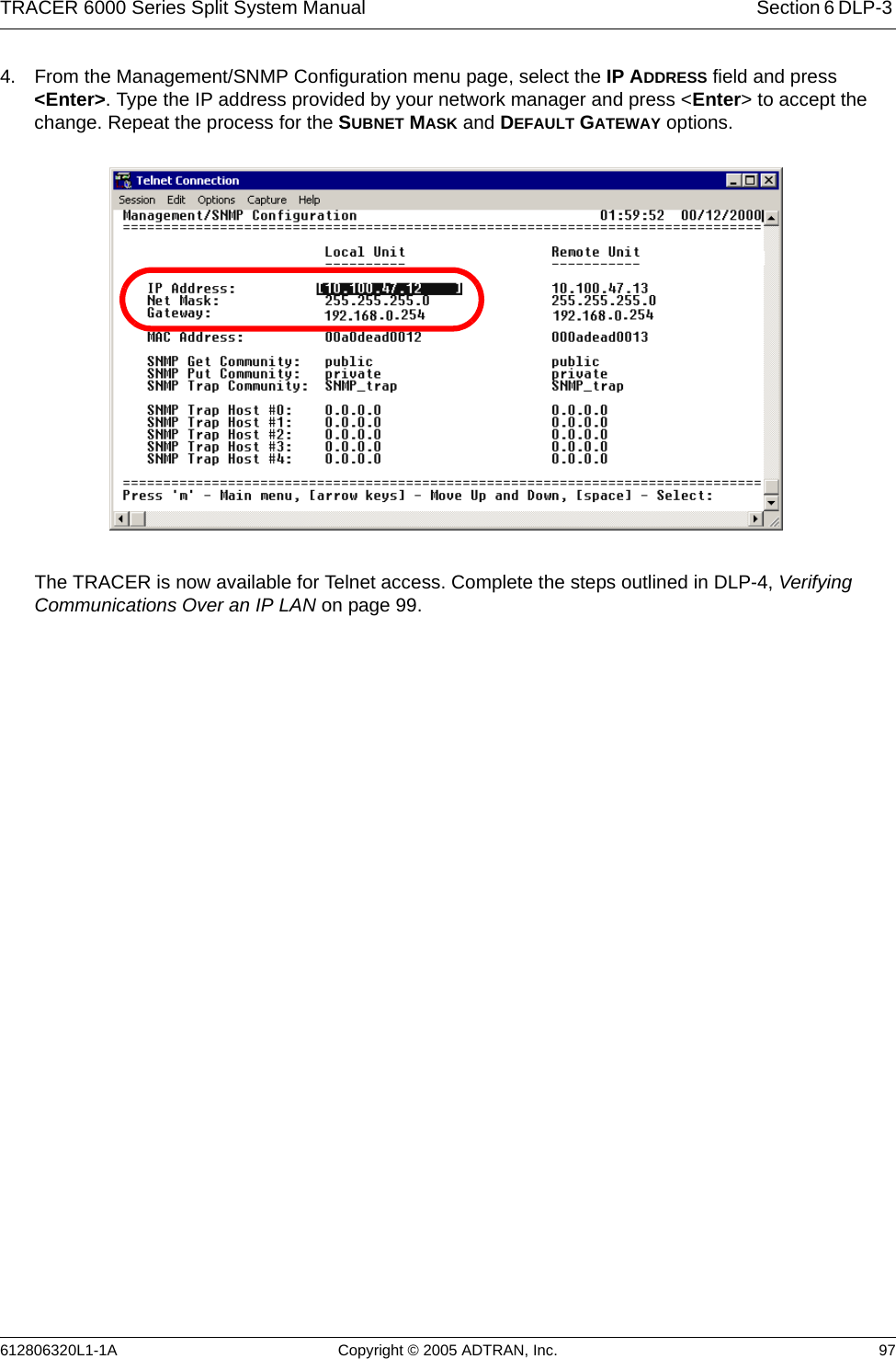
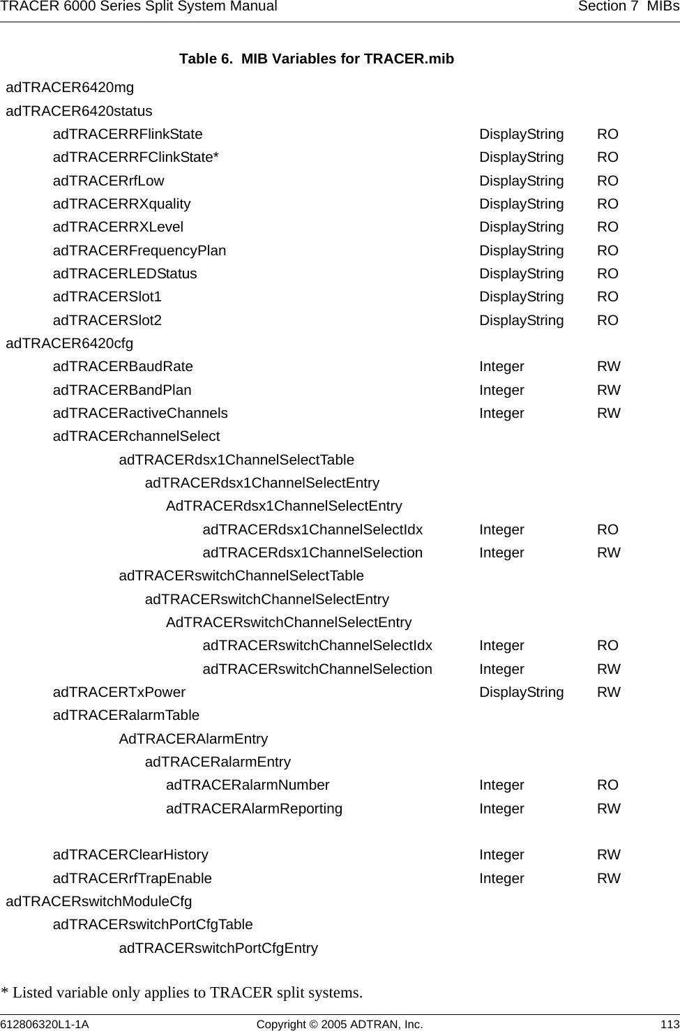
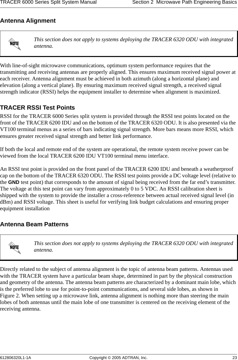
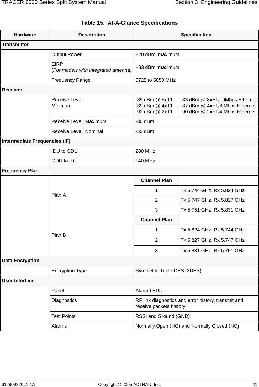
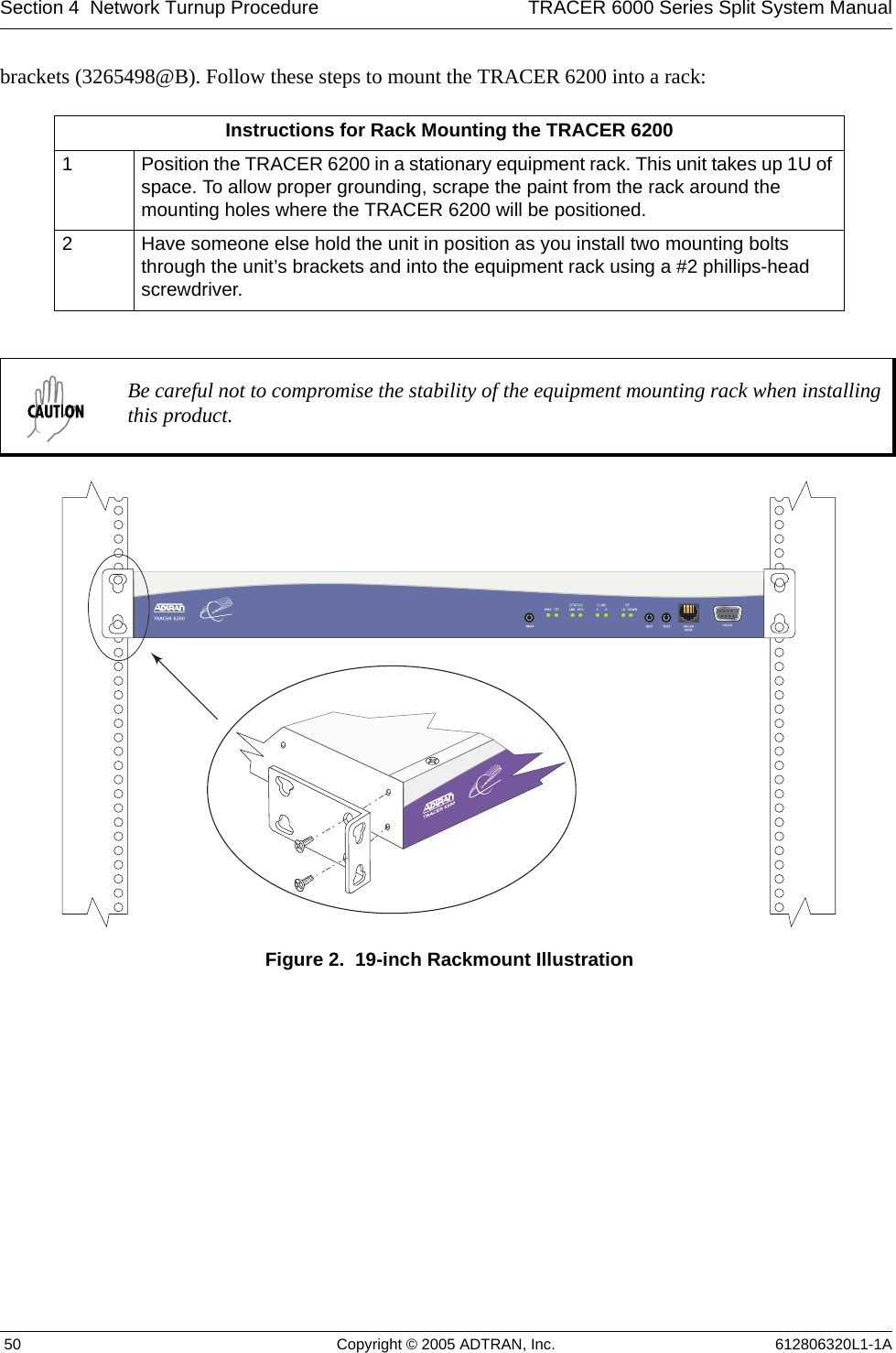
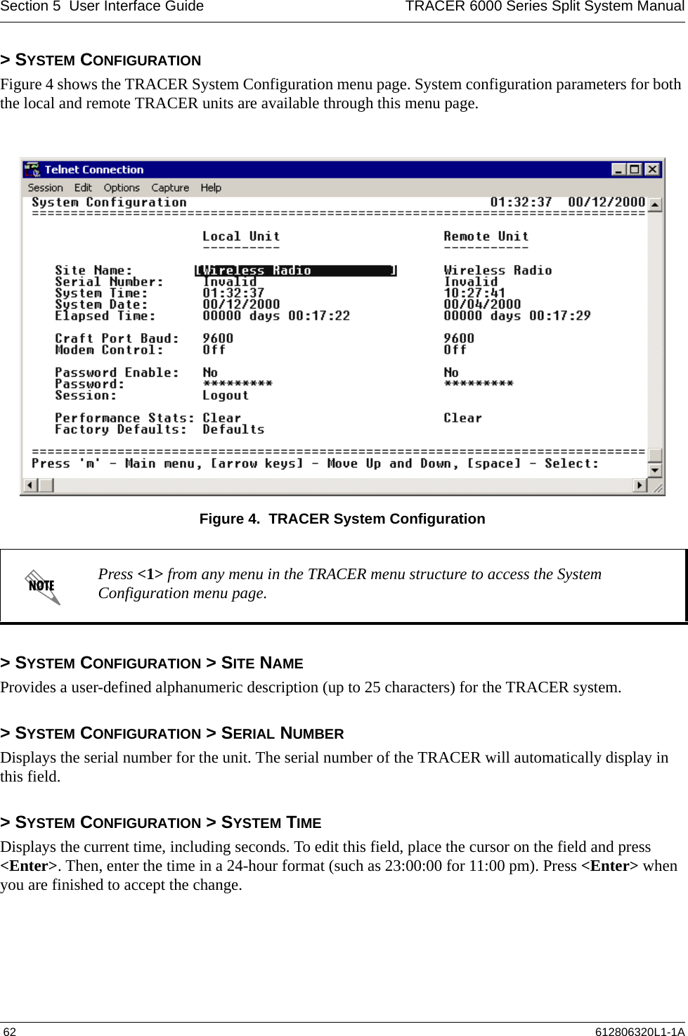
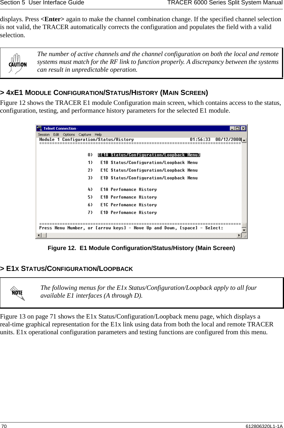
![TRACER 6000 Series Split System Manual Section 5 User Interface Guide612806320L1-1A 77> T1X STATUS/CONFIGURATION/LOOPBACK > LOOP/NORMAL STATE > LINE [REMOTE]Activates a loopback at the remote TRACER T1 framer towards the connected T1 equipment at the remote end of the link (see Figure 17). Use the remote LINE loopback to test data path integrity from the remote TRACER unit to the T1 equipment connected at the remote end of the link.Figure 24. T1 Remote Line Loopback> T1X PERFORMANCE HISTORYFigure 25 shows the T1x Performance History menu page, which displays detailed error statistics for the T1 link (from both the local and remote TRACER units) in 15-minute and 24-hour increments.Figure 25. T1x Link Performance HistoryT1 performance data is presented as Errored Seconds (ES) and Severely Errored Seconds (SES) on the T1 interface. The following events qualify as an ES: AIS, LOS or LOF alarm second, a single BPV, excessive zero event, or a single parity bit. An SES is caused by an AIS, LOS or LOF alarm second, excessive BPVs, or framed parity-bit errors causing a line bit error rate (BER) of 10-6.The error counts for the most recent 24 hours are recorded in 15-minute increments and displayed on the right side of the page. The left side of the page displays the 24-hour totals for the most recent 7 days.The following menus for the T1x Performance History apply to all four available T1 interfaces (A through D).Press <n> to view the next 8-hour segment of 15-minute totals and <p> to view the previous 8-hour segment.24 Hours7 Days(8 Hours displayed at a Time)](https://usermanual.wiki/ADTRAN/TRC6320/User-Guide-537882-Page-77.png)