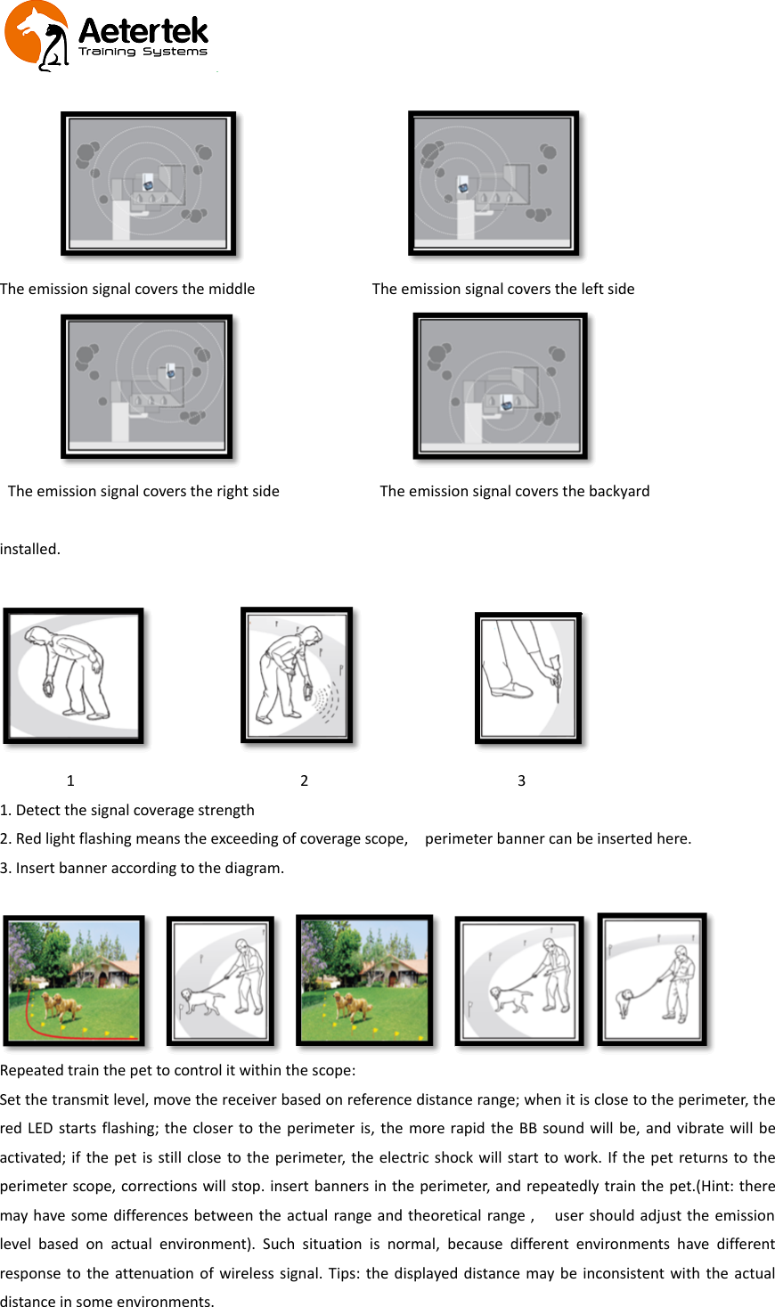
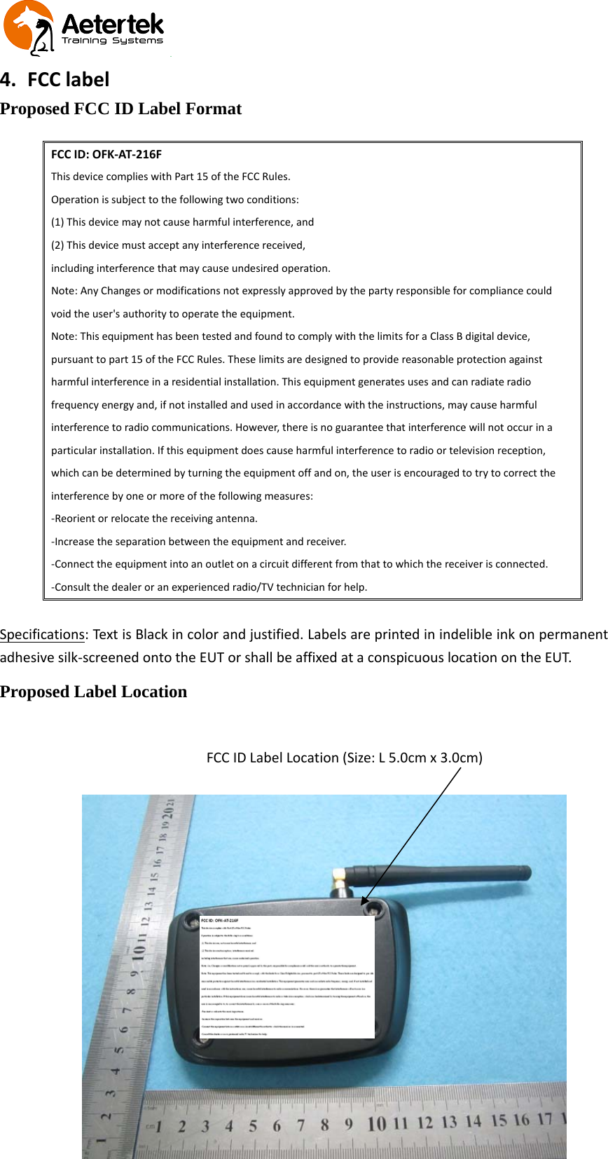
Aetertek Technology AT-216F Remote dog trainer & fence User Manual

Shenzhen Aetertek Technology Co.,Ltd Remote dog trainer & fence Users Manual

User Manual

Wireless Fence (AT-216F)Signal coverage diameter is 1‐50mDetection signal coverage area will lay the banner inside
1、Function Description:
2、Working parameter tableProduct DescriptionFrequency bands: transmitter 915MHZFrequency bands: Receive 915MHZSupply voltage transmitter DC 5VSupply voltage Receive 3.7VOutput power 2.5WattsReceive sensitivity -116DBMData rate 38.4 kbps / 2-FSKOperating temperature:−20 -----55·CGeneralSuited for systems targeting complianceWith EN 300 220 V2.3.1 (Europe)FCC CFR Part 15 (US)3、Operating Guide3.1 Transmitter1. Open the package, take out the transmitter, align the RF antenna at the RF connector, rotate clockwise andtighten the nut.2. Plug the charger into the DC jack of the transmitter, the transmitter will enter the status of emission; theantenna symbol in the display starts flashing, indicating the transmitter to start work. The lower right cornershows the current power.3. The transmitter coverage distance can be adjusted by up and down buttons; the center of the display showsthe current distance between the emission level and reference signal coverage. Adjust the level according touser needs. Level 00‐10 is the strength level display of coverage signal; the higher the value is, the larger thecoverage distance is. The center of the display will show the reference distance range of the current level(note: in some special environment, when there is difference between the reference distance range and theactual distance, the signal coverage range can be adjusted by intensity increase or decrease according touser needs.). 00 level is the way of turning off electric shock.4. To enter or exit menu setting by pressing M button. After entry, the BB sound, vibration and shock functioncan be selected repeatedly by left and right buttons. After setting menu icon starts flashing, the BB sound,
vibration and shock can be turned off by pressing the up and down buttons. (ON means relevant functionturned on, OFF means relevant function turned off). Shock includes two modes, i.e, AUTO and MANUAL. InAuto Mode, in Auto mode, transmitter emits suitable level shock intelligently, while in the mode of MANUAL,user can set the suitable shock level. After setting the relevant function and level, press the menu button cansave the setting and exit programming.3.2 Receiver1. Open the package, take out the receiver and install the shock prongs; charges the receiver at the first time;the first few charging time should be more than 3 hours, that will prolong battery life.2. To charge the receiver, plug the charger connector into the charging port on the receiver, at this time, the BBsound and vibration will be activated by one time and the red LED light will turn on to indicate it is incharging. After 3‐4 hours, the blue LED light will turn on to indicate the charging is completed. unpluggingthe charger, receiver will beep and vibrate by one time to indicate that the charging disrupted. (Note: pleasecover the charge port lid in usage).3. Press the On/Off button for 3 seconds, receiver will beep and vibrate by one time to indicate receiver ispowered on. If the transmitter is in working status, the receiver will communicate with transmitterautomatically and start to work.4. Put shock prongs onto two screws on the bottom of receiver, then turn on the receiver, receiver will self‐testby Beep, vibrate and shock by one time, if everything is right, wear receiver on the pet’s neck.5. Shock prongs must touch dog’s skin to ensure perfect shock effect , but should not stress too tight that willmake dog uncomfortable.3.3 Scope of adjustment region
The emission signal covers the middle The emission signal covers the left sideThe emission signal covers the right side The emission signal covers the backyardinstalled.1231. Detect the signal coverage strength2. Red light flashing means the exceeding of coverage scope, perimeter banner can be inserted here.3. Insert banner according to the diagram.Repeated train the pet to control it within the scope:Set the transmit level, move the receiver based on reference distance range; when it is close to the perimeter, thered LED starts flashing; the closer to the perimeter is, the more rapid the BB sound will be, and vibrate will beactivated; if the pet is still close to the perimeter, the electric shock will start to work. If the pet returns to theperimeter scope, corrections will stop. insert banners in the perimeter, and repeatedly train the pet.(Hint: theremay have some differences between the actual range and theoretical range , user should adjust the emissionlevel based on actual environment). Such situation is normal, because different environments have differentresponse to the attenuation of wireless signal. Tips: the displayed distance may be inconsistent with the actualdistance in some environments.
4. FCC labelProposed FCC ID Label FormatFCC ID: OFK‐AT‐216FThis device complies with Part 15 of the FCC Rules.Operation is subject to the following two conditions:(1) This device may not cause harmful interference, and(2) This device must accept any interference received,including interference that may cause undesired operation.Note: Any Changes or modifications not expressly approved by the party responsible for compliance couldvoid the user's authority to operate the equipment.Note: This equipment has been tested and found to comply with the limits for a Class B digital device,pursuant to part 15 of the FCC Rules. These limits are designed to provide reasonable protection againstharmful interference in a residential installation. This equipment generates uses and can radiate radiofrequency energy and, if not installed and used in accordance with the instructions, may cause harmfulinterference to radio communications. However, there is no guarantee that interference will not occur in aparticular installation. If this equipment does cause harmful interference to radio or television reception,which can be determined by turning the equipment off and on, the user is encouraged to try to correct theinterference by one or more of the following measures:‐Reorient or relocate the receiving antenna.‐Increase the separation between the equipment and receiver.‐Connect the equipment into an outlet on a circuit different from that to which the receiver is connected.‐Consult the dealer or an experienced radio/TV technician for help.Specifications: Text is Black in color and justified. Labels are printed in indelible ink on permanentadhesive silk‐screened onto the EUT or shall be affixed at a conspicuous location on the EUT.Proposed Label LocationFCC ID Label Location (Size: L 5.0cm x 3.0cm)

Navigation menu