Contents
- 1. user manual
- 2. User manual
- 3. user manual revised
user manual

Airaya
- 1 -
Airaya Proven, Fast and Affordable Outdoor Wireless Bridges
Product Manual
And Installation Guide
WirelessGRID-300 MIMO Outdoor Wireless Bridges
Revision 2.02
11/29/2010 10:00 PM
WirelessGRID-300
High Capacity Outdoor Backhaul Radios
For Point-to-point Links

- 2 -
Airaya
WirelessGRID
-
300 Backhaul
AIRAYA is a trademark of AIRAYA Corp. Other trademarks or brand
names mentioned herein are trademarks or registered trademarks of their
respective companies.
International Headquarters
18434 Technology Drive
Morgan Hill, CA 95037
Tel: 866-224-7292
Tel: 408-776-2846 International
Fax 408-776-3339
E-mail: support@airaya.com
Skype: airaya_support
Web site: www.airaya.com
Copyright © 2009 by AIRAYA Corp. All rights reserved.
No part of this document may be copied or reproduced in any form or by
any means without the prior written consent of AIRAYA Corp.
AIRAYA makes no warranties with respect to this documentation and
disclaims any implied warranties of merchantability, quality, or fitness for
any particular purpose. The information in this document is subject to
change without notice. AIRAYA reserves the right to make revisions to
this publication without obligation to notify any person or entity of any
such changes.

Airaya
- 3 -
Airaya Proven, Fast and Affordable Outdoor Wireless Bridges
Limited Warranty
AIRAYA Corp.
Limited Warranty: AIRAYA warrants all of its products to be free of
manufacturing defects in workmanship and materials, under normal use
and service, for the applicable warranty term. All AIRAYA products carry a
standard 90-day limited warranty from the date of purchase from AIRAYA
or its Authorized Reseller. AIRAYA may, at its own discretion, repair or
replace any product not operating as warranted with a similar or
functionally equivalent product during the applicable warranty term.
The standard limited warranty can be upgraded to a one-year warranty
by registering new products within 30 days of purchase from AIRAYA or
its Authorized Reseller. Registration can be accomplished online via the
AIRAYA web site. Failure to register will not affect the standard limited
warranty. The one-year warranty covers a product during the Life of that
Product, which is defined as the period of time during which the product is
an ‘Active’ AIRAYA product. A product is considered to be ‘Active’ while it
is listed on the current AIRAYA price list. As new technologies emerge,
older technologies become obsolete and AIRAYA will, at its discretion,
replace an older product in its product line with one that incorporates
these newer technologies. At that point, the obsolete product is
discontinued and is no longer an ‘Active’ AIRAYA product.
All products that are replaced become the property of AIRAYA.
Replacement products may be either new or reconditioned. Any replaced
or repaired product carries either a 30-day limited warranty or the
remainder of the initial warranty, whichever is longer. AIRAYA is not
responsible for any custom software or firmware, configuration
information, or memory data of Customer contained in, stored on, or
integrated with any products returned to AIRAYA pursuant to any
warranty. Products returned to AIRAYA should have any customer-
installed accessory or add-on components removed prior to returning the
product for replacement. AIRAYA is not responsible for these items if they
are returned with the product.
Customers must contact AIRAYA for a Return Material Authorization
(RMA) number prior to returning any product to AIRAYA. Proof of
purchase may be required. Any product returned to AIRAYA without a
valid RMA number clearly marked on the outside of the package will be
returned to customer at customer’s expense. Customers are responsible
for all shipping charges from their facility to AIRAYA. AIRAYA is
responsible for return shipping charges from AIRAYA to the customer.

- 4 -
Airaya
WirelessGRID
-
300 Backhaul
Limited Warranty
WARRANTIES EXCLUSIVE: IF AN AIRAYA PRODUCT DOES NOT OPERATE
AS WARRANTED ABOVE, CUSTOMER’S SOLE REMEDY SHALL BE REPAIR
OR REPLACEMENT OF THE PRODUCT IN QUESTION, AT AIRAYA’S OPTION.
THE FOREGOING WARRANTIES AND REMEDIES ARE EXCLUSIVE AND ARE
IN LIEU OF ALL OTHER WARRANTIES OR CONDITIONS, EXPRESS OR
IMPLIED, EITHER IN FACT OR BY OPERATION OF LAW, STATUTORY OR
OTHERWISE, INCLUDING WARRANTIES OR CONDITIONS OF
MERCHANTABILITY AND FITNESS FOR A PARTICULAR PURPOSE. AIRAYA
NEITHER ASSUMES NOR AUTHORIZES ANY OTHER PERSON TO ASSUME
FOR IT ANY OTHER LIABILITY IN CONNECTION WITH THE SALE,
INSTALLATION, MAINTENANCE OR USE OF ITS PRODUCTS. AIRAYA
SHALL NOT BE LIABLE UNDER THIS WARRANTY IF ITS TESTING AND
EXAMINATION DISCLOSE THE ALLEGED DEFECT IN THE PRODUCT DOES
NOT EXIST OR WAS CAUSED BY CUSTOMER’S OR ANY THIRD PERSON’S
MISUSE, NEGLECT, IMPROPER INSTALLATION OR TESTING,
UNAUTHORIZED ATTEMPTS TO REPAIR, OR ANY OTHER CAUSE BEYOND
THE RANGE OF THE INTENDED USE, OR BY ACCIDENT, FIRE, LIGHTNING,
OR OTHER HAZARD.
LIMITATION OF LIABILITY: IN NO EVENT, (INCLUDING NEGLIGENCE),
SHALL AIRAYA BE LIABLE FOR INCIDENTAL, INDIRECT, SPECIAL, OR
PUNITIVE DAMAGES OF ANY KIND, OR FOR LOSS OF REVENUE, LOSS OF
BUSINESS, OR OTHER FINANCIAL LOSS ARISING OUT OF OR IN
CONNECTION WITH THE SALE, INSTALLATION, MAINTENANCE, USE,
PERFORMANCE, FAILURE, OR INTERRUPTION OF ITS PRODUCTS, EVEN IF
AIRAYA OR ITS AUTHORIZED RESELLER HAS BEEN ADVISED OF THE
POSSIBILITY OF SUCH DAMAGES.
SOME COUNTRIES DO NOT ALLOW THE EXCLUSION OF IMPLIED
WARRANTIES OR THE LIMITATION OF INCIDENTAL OR CONSEQUENTIAL
DAMAGES FOR CONSUMER PRODUCTS, SO THE ABOVE LIMITATIONS
AND EXCLUSIONS MAY NOT APPLY TO YOU. THIS WARRANTY GIVES YOU
SPECIFIC LEGAL RIGHTS, WHICH MAY VARY FROM STATE TO STATE.
NOTHING IN THIS WARRANTY SHALL BE TAKEN TO AFFECT YOUR
STATUTORY RIGHTS.
Note: AIRAYA will provide fee-based service for up to three years
following discontinuance of any product from the active AIRAYA price list.
Under the one-year warranty, internal and external power supplies, and
fans are covered by a standard one-year warranty from date of purchase.

Airaya
- 5 -
Airaya Proven, Fast and Affordable Outdoor Wireless Bridges
Regulatory Information
and Industry Canada Guidelines
The radiated output power of the AIRAYA WirelessGRID-300 Wireless Bridge is
far below the FCC radio frequency exposure limits. Nevertheless, the device
shall be used in such a manner that the potential for human contact during
normal operation is minimized. It is the responsibility of the installer and
users of the WirelessGRID-300 to guarantee that the antenna(s) operates at
least 30 centimeters (11.8 inches) from any person operating in the 5.8 Ghz
band and at least 50 centimeters (19.7 inches) from any person operating in
the 4.9 GHz band. This is necessary to insure that the product operates in
accordance with the Federal Communications Commission’s RF Guidelines for
Human Exposure.
The WirelessGRID-300’s antennas may NOT be replaced at any time. They are
designed to comply with the maximum EIRP limits specified by the FCC and
Industry Canada. Modifications to the WirelessGRID-300, unless expressly
approved by AIRAYA, could void the user’s authority to operate the
equipment.
FCC ID: QDE-GRID-3X3-PS IC: 4433A-GRID3X3PS
IC Warning message:
Operation of this device is subject to the following two conditions: (1) this device may not cause
interference, and (2) this device must accept any interference, including interference that may
cause undesired operation of the device.
If the antenna is detachable (ie. selectable by the user, can be change. Otherwise it calls
integrated), needs to include 7.1.4 and 7.1.5 in the manual:
7.1.4 has statement for detachable antenna.
“
This device has been designed to operate with the antennas listed below, and having a
maximum gain of 29 dB. Antennas not included in this list or having a gain greater than 29 dB
are strictly prohibited for use with this device. The required antenna impedance is 50 ohms.”
7.1.5 has additional statement for detachable antenna.
“
To reduce potential radio interference to other users, the antenna type and its gain should be
so chosen that the equivalent isotropically radiated power (e.i.r.p.) is not more than that
permitted for successful communication.”
FCC Warning message:
This equipment complies with FCC radiation exposure limits set forth for an uncontrolled
environment. This equipment should be installed and operated with minimum 50 cm for the
4.9Ghz band usage, 30cm for 5.8Ghz Point-to-Point operation and 20cm for 5.8 Ghz Point-to-
Multipoint between the radiator and your body. This transmitter must not be collocated or
operating in conjunction with any other antenna or transmitter unless authorized to do so by the
FCC.

- 6 -
Airaya
WirelessGRID
-
300 Backhaul
Contents
Introduction ....................................................................................................................... 8
Package Checklist .............................................................................................. 8
Hardware Description ........................................................................................................ 10
Ethernet Compatibility ...................................................................................... 10
Radio Characteristics ........................................................................................ 10
Antenna Options for 5 GHz Operation.................................................................. 10
Outdoor Nema4 Enclosure ................................................................................. 11
Cabling and Cable Bulkhead Fittings ................................................................... 11
Remote PoE Power ........................................................................................... 11
Backhaul / Point-to-point Architecture .................................................................................. 11
System Requirements........................................................................................................ 13
Hardware Installation ........................................................................................................ 14
Connecting the Indoor Injector Unit .................................................................... 14
Software Configuration ...................................................................................................... 16
Getting Started................................................................................................ 16
Logging into the WirelessGRID-300 Web-based NMS ............................................. 16
Current Settings .............................................................................................. 18
Wired Network Settings .................................................................................... 18
Radio Network Settings..................................................................................... 18
WirelessGRID-300 Bridge List ............................................................................ 19
WirelessGRID-300 System Setup Tab.................................................................. 20
Network Settings Tab ....................................................................................... 22
Radio Settings Tab ........................................................................................... 24
Admin Setup Tab ............................................................................................. 26
Security Tab – Data Encryption .......................................................................... 28
WirelessGRID-300 Authentication ....................................................................... 28
Data Encryption ............................................................................................... 29
Encryption Key Manager ................................................................................... 29
Active Bridge Status Tab ................................................................................... 31
Remote Bridge (SU Station) Statistics Tab ........................................................... 32
Firmware Update Tab ....................................................................................... 34
Help Tab......................................................................................................... 35
Appendix A – Bench Test Procedure ..................................................................................... 36
Step 1. Setup a wired Ethernet network between test stations................................ 36
Step 2. Setup wired Ethernet network connections to bridges................................. 37

Airaya
- 7 -
Airaya Proven, Fast and Affordable Outdoor Wireless Bridges
Step 3. Setup bridge software configuration for bridge .......................................... 38
Step 4. Test network connectivity across a WirelessGRID-300 link .......................... 39
Step 4a. Check throughput of WirelessGRID-300 link (optional).............................. 40
Step 5. Field deployment of WirelessGRID-300 bridges.......................................... 42
Appendix A: Weatherproofing RF Cable Connections............................................................... 43
How to Get Help ............................................................................................................... 44
Worldwide Web Support.................................................................................... 44
Contacting AIRAYA ........................................................................................... 44

- 8 -
Airaya
WirelessGRID
-
300 Backhaul
Introduction
AIRAYA WirelessGRID-300 series wireless bridges have been designed to
provide transparent, high-speed data communications between two or
more locations.
The WirelessGRID-300 utilizes detachable antennas and is an outdoor
radio product, with external antenna connections. The product requires
installation by a certified professional installer, only.
WirelessGRID-300 firmware will not allow the end user to change or
modify the country code settings of this product. The availability of
specific channels and/or operational frequency bands are country
dependent and are programmed in firmware to match the intended
destination, by AIRAYA Corp. factory personnel only. The US Country
Code setting will only allow operation in the 5.725-5.850 GHz band for 20
& 40 MHz wide channels. The PS Country Code will allow operation in the
5.725-5.850 GHz band for 20 & 40 MHz wide channels, while also
allowing the use of 4.940-4.990 GHz band with bandwidths of 5, 10, 15 &
20 MHz wide channels.
This solution offers proven, fast, reliable, and secure wireless connectivity
with considerable cost savings compared to wired alternatives. Utilizing
proprietary 4.940-4.990 & 5.725-5.850 GHz technology, the
WirelessGRID-300 bridge can easily replace an Ethernet or multiple T1
connections or seamlessly integrate into a newer 1000/100 Mbps Ethernet
Local Area Network (LAN).
Package Checklist
Each WirelessGRID-300 bridge comes in either one or two cartons,
depending on the model ordered, and contains the following components:
Two outdoor units with either two (2) or three (3) N-type Female
Connectors
Pole mounting hardware and brackets
Two indoor injector units and full range power supplies for remote
power
Two 48 VDC .4 Amp power bricks
Two UV-protected outdoor-rated cables (length specified by part
number) or Bulkhead fittings for Gigabit remote PoE power cables.
Please register your product online at: www.airaya.com in the support/
product registration section of our web site. Note: Free technical support
is only available to registered users of AIRAYA equipment.

Airaya
- 9 -
Airaya Proven, Fast and Affordable Outdoor Wireless Bridges
Please inform your dealer if there are any incorrect, missing, or damaged
parts. If possible, retain the carton and original packing materials for
repacking purposes in case you need to return a radio bridge for repair.

- 10 -
Airaya
WirelessGRID
-
300 Backhaul
Hardware Description
Ethernet Compatibility
WirelessGRID-300 wireless bridges can be attached directly to 10BASE-
100/1000 BASE-TX (twisted-pair) Ethernet LAN segments. These
segments must conform to the IEEE 802.3 specification.
Each WirelessGRID-300 bridge functions as an Ethernet node and
performs layer 2 bridging by moving packets from a network in one
building to a network in another building.
Radio Characteristics
WirelessGRID-300 bridges utilizes a radio modulation technique known as
Orthogonal Frequency Division Multiplexing (OFDM) capable of operating
in the4.940-4.990 & 5.725-5.850 GHz bands. Data is transmitted over a
radio channel at signaling rates up to 300 Mbps in 5.8 GHz band and 130
Mbps in the 4.9 GHz band.
Antenna Options for 5 GHz Operation
The outdoor version of the WirelessGRID-300 bridge uses FCC certified
antennas to achieve a maximum operating range up to 30 miles under FCC
rules in the 5.8 GHz band. When using antenna in the 4.9 GHz band, an
antenna gain greater than 26 dBi, will require the user to reduce the radio
output power by the amount of gain abover 26 dBi.
This device has been designed to operate with the antennas listed
below in the 5.8 GHz band only, and having a maximum gain of 29 dB.
Antennas not included in this list or having a gain greater than 29 dB
are strictly prohibited for use with this device. The required antenna
impedance is 50 ohms.
To reduce potential radio interference to other users, the antenna type and its
gain should be so chosen that the equivalent isotropically radiated power
(e.i.r.p.) is not more than that permitted for successful communication.
4.9 Ghz Band Antenna Operation
Antenna
Gain
Max
Transmit
Power
EIRP Antenna Type
29 dBi 23.00 52.00
dBm
Grid /Dish Parabolic
Antennas
23.5 dBi 24.96
dBm
48.46
dBm
Dual Polarized Antenna
23 dBi 24.96
dBm
47.96
dBm
Patch Antenna
17 dBi 24.96
dBm
41.96
dBm
Vertically Polarized Sector
Antenna
10 dBi 24.96
dBm
34.96
dBm
Omni Directional Antenna
Airaya
- 11 -
Airaya Proven, Fast and Affordable Outdoor Wireless Bridges
5.8 Ghz Band Antenna Operation
Outdoor Nema4 Enclosure
The metal enclosure of WirelessGRID-300 bridge has been designed for
maximum durability for outdoor use in a range of weather conditions.
They are watertight and meet NEMA/EEMAC Type 4 and IP66
specifications.
Cabling and Cable Bulkhead Fittings
The outdoor version of the WirelessGRID-300 bridge includes Category 5e
cables designed for outdoor applications. This cable supports DC Power
Over Ethernet for easy installation. The bulkhead fitting is an IP67-rated
Ethernet Fitting for use in outdoor applications.
Remote PoE Power
Gigabit Power Over Ethernet (IEEE802.3AF) is an integral part of the
WirelessGRID-300 bridge. The injector is capable of providing power at
the full distance specified by the IEEE 802.3 Ethernet specification (100
meters).
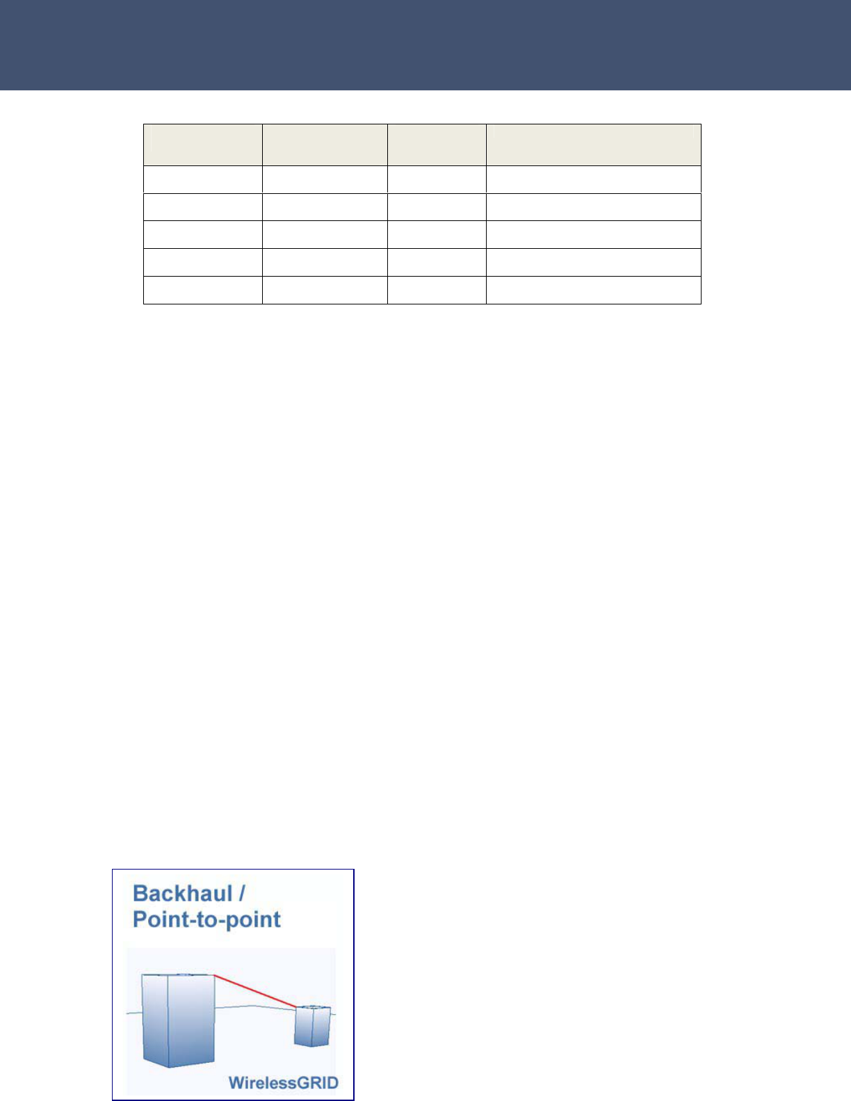
Backhaul / Point-to-point Architecture
Figure 1. This diagram illustrates a typical use scenario of a
WirelessGRID-300 bridge interconnecting two networks in separate
facilities.
Antenna
Gain
Max
Transmit
Power
EIRP Antenna Type
29 dBi 24.96
dBm
53.96
dBm
Grid /Dish Parabolic
Antennas
23.5 dBi 24.96
dBm
48.46
dBm
Dual Polarized Antenna
23 dBi 24.96
dBm
47.96
dBm
Patch Antenna
17 dBi 24.96
dBm
41.96
dBm
Vertically Polarized Sector
Antenna
10 dBi 24.96
dBm
34.96
dBm
Omni Directional Antenna

- 12 -
Airaya
WirelessGRID
-
300 Backhaul
For complete information on model numbers, please refer to the ordering guide located
on the AIRAYA website.

Airaya
- 13 -
Airaya Proven, Fast and Affordable Outdoor Wireless Bridges
System Requirements
Before installing the WirelessGRID-300 bridge, be sure you have the
following items on-hand:
An AC power outlet (100 to 240 V, 50 to 60 Hz) to supply power to
the indoor injector units on both sides of the wireless link
An outdoor unit mast with a 1 to 4 inch (25.4 to 101.6 mm)
diameter
An available RJ-45 (UTP) port on a 1000/100 Mbps Ethernet switch
or router
Web browser or telnet (CLI) application for software configuration
The WirelessGRID-300 bridge has been designed to withstand normal
handling procedures, but reasonable precautions should be taken during
installation, particularly with regard to static discharge.
• Make sure that you are adequately grounded by touching the bare
metal surface on the back of a computer or networking device
before installing the indoor and outdoor units.
• Avoid moving around the work area in order to eliminate static
charge buildup.
• If possible, do not work on a carpeted area.
- 14 -
Airaya
WirelessGRID
-
300 Backhaul
Hardware Installation
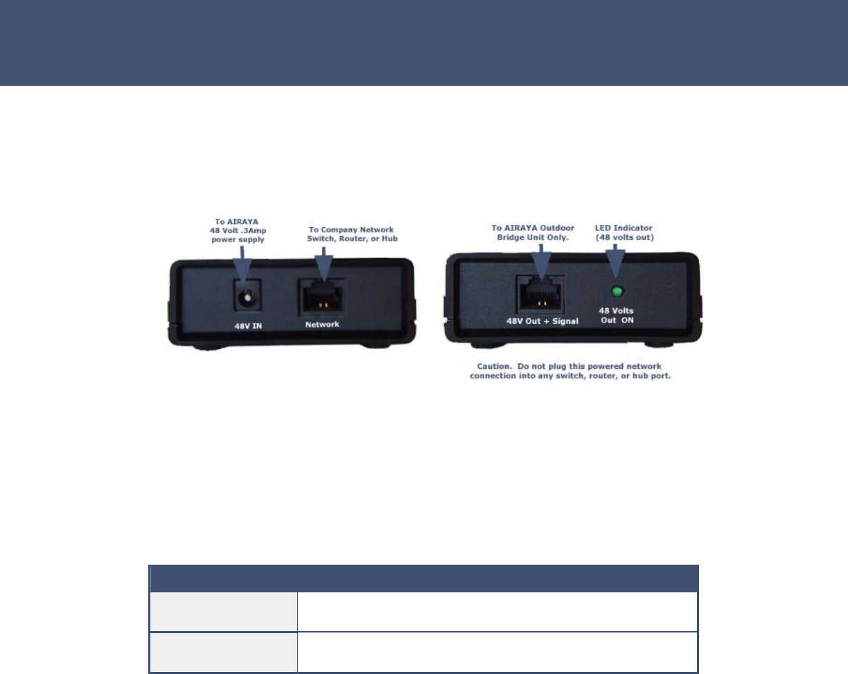
Connecting the Indoor Injector Unit
Figure 5. Network and outdoor connection views
The indoor injector unit connects your company network to the outdoor
portion of the WirelessGRID-300 bridge and delivers both data and
power. The indoor portion of the remote power system features the
following LED status indicators:
LED Indication
Power Brick LED
(green)
Power source is active and supplying 48 volts to the indoor
injector unit
Injector 48V out
(green)
Power Over Ethernet is active and the injector is hot at the
48V Out+ Signal port
Before you mount the indoor Injector unit at a fixed location, consider the
following requirements to determine optimal placement:
• The cable length from the Ethernet switch or router to the
outdoor unit must not exceed 328 feet (100 meters).
• Placement must allow for easy access to disconnect the
indoor injector unit from the AC outlet if necessary.
Airaya
- 15 -
Airaya Proven, Fast and Affordable Outdoor Wireless Bridges
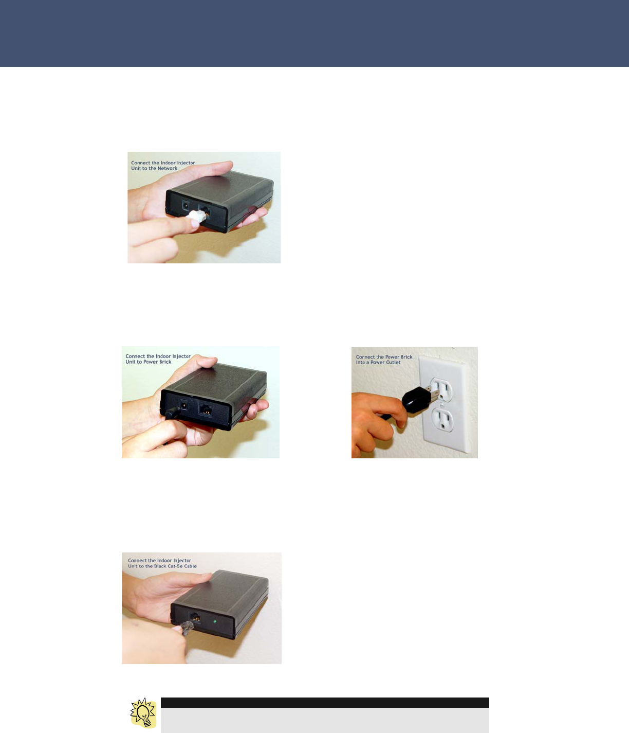
Follow these steps to install the indoor injector unit:
1. Connect the To Network port on the indoor injector unit to your
1000/100 Mbps Ethernet switch or router using a straight-through
Category 5 UTP cable.
2. Connect the power brick to the 48 VDC In power socket on the indoor
injector unit and then plug the power brick into the wall power
receptacle. Warning: Use only the power adapter supplied with the
WirelessGRID-300 bridge in order to prevent damage.
3. You are now ready to apply power to the outdoor unit. Connect the 48V
OUT + Signal port to the outdoor unit using the included (black)
Category 5e cable attached to the outdoor unit. The 48V OUT LED will
light to indicate that the indoor injector unit is active and outputting 48
volts, .4 amps to the 48V OUT + Signal port.
TIP
After applying power to the outdoor unit, the link light on your network
connection (Switch or Router Port) should be on.
- 16 -
Airaya
WirelessGRID
-
300 Backhaul
Software Configuration
You can configure the network, radio, and security parameters of the
WirelessGRID-300 bridge using the built-in WirelessGRID-300 Network
Management System (NMS). This web-based configuration utility greatly
simplifies the setup process by allowing you to access all parameters and
settings through a single, consistent user interface.
Getting Started
The factory default IP address of the WirelessGRID-300 bridge is
192.168.1.70. Type that string into the address field of your browser and
press the Return key to load the WirelessGRID-300 NMS.
You will be prompted for a User Name and Password. Refer to the next
section for information about default settings.
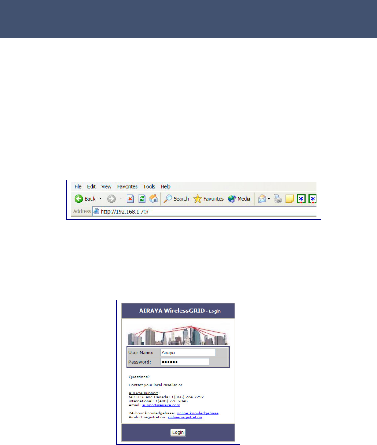
Logging into the WirelessGRID-300 Web-based NMS
The WirelessGRID-300 bridge requires you to enter a user name and
password to gain access to the configuration utility. The default User
Name and Password is “Airaya.”
Airaya
- 17 -
Airaya Proven, Fast and Affordable Outdoor Wireless Bridges
Once logged in, you can access all available WirelessGRID-300
configuration options. The web interface is organized into tabs that allow
you to access screens that let you view and change bridge parameters.
Tabs include Current Settings, Network Settings, Radio Settings, Admin
Setup, Advanced, Authorized Bridges, Data Encryption, Active Bridges,
Station Stats, Download Updates and screen-specific Help.
The following sections describe the entries in each area of the Current
Settings screen:

- 18 -
Airaya
WirelessGRID
-
300 Backhaul
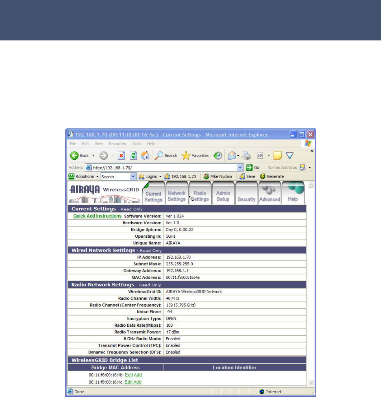
Current Settings
Quick Add Instructions – Step-by-step instructions to set up and add a
new bridge to a WirelessGRID-300 network.
Software Version – Current software (firmware) version installed on the
bridge.
Hardware Version – Current hardware version of the bridge you’re
connected to.
Bridge Uptime – Amount of time the bridge has been active since the
last reboot.
Operating In – Specifies the general frequency range of bridge
operation.
Unique Name – A unique identifier with up to 32 characters, which is
commonly used as a location identifier. Control characters are not allowed
in this field.
Wired Network Settings
IP Address – IP address of the bridge. The IP address for each bridge
must be unique, so please check with your network administrator for the
correct IP address assigned to your device.
Subnet Mask – Current subnet mask of the bridge you are working with.
The subnet mask allows networking software to determine which parts of
the IP address specify the network address and which parts specify the
host address.
Gateway Address – Current gateway address of the bridge you are
working with. IP packets destined for other subnets are automatically
sent to the default gateway, which routes traffic to the correct network.
MAC Address – Unique Ethernet address of bridge you are working with.
Radio Network Settings
WirelessGRID-300 ID – Displays a unique network ID. All bridges in a
WirelessGRID-300 network are required to use the same WirelessGRID-
300 ID.
Radio Channel Width – Current channel width (measured in Megahertz)
of the bridge.

Airaya
- 19 -
Airaya Proven, Fast and Affordable Outdoor Wireless Bridges
Radio Channel (center frequency) – Current channel and center
frequency of the bridge.
Noise Floor – Measurement of ground floor noise level calculated at
startup of bridge.
Encryption Type – Data encryption type selected for bridge (e.g. Open,
AES).
Radio Data Rate – Current radio data rate setting. Available options for
data rates are based on channel size.
Radio Transmit Power – Current radio transmit power setting.
5 GHz Radio Mode – Current mode (e.g. enabled, disabled).
Transmit Power Control (TPC) – Current status of TPC (e.g. enabled
or disabled).
Dynamic Frequency Selection (DFS) – Current status of DFS (e.g.
enabled or disabled).
WirelessGRID-300 Bridge List
Authorization List of all bridges allowed to associate and communicate
with the bridge you are working with.
Bridge MAC Address – MAC address of bridge configured to access a
WirelessGRID-300 network. This entry is required for each bridge allowed
in the WirelessGRID-300 network.
Edit or Add – Links that you can select to update or add new bridges to
authorized WirelessGRID-300 bridge list.
- 20 -
Airaya
WirelessGRID
-
300 Backhaul
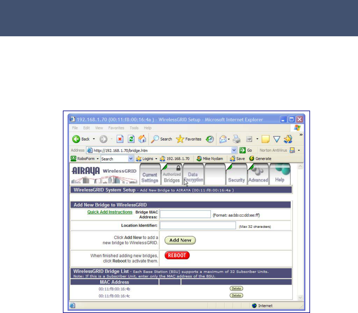
WirelessGRID-300 System Setup Tab
The WirelessGRID-300 System Setup screen is used to add or delete
remote Bridge MAC addresses from the authorized bridge list. Each
bridge contains a WirelessGRID-300 authorization list, and all bridges
require reciprocal entries to communicate.
The Add New Bridge to WirelessGRID-300 section of the screen contains the
following entries:
Quick Add Instructions – Step-by-step instructions to set up and add a
new bridge to a WirelessGRID-300 network
Bridge MAC Address – The MAC address of a remote bridge you want
authorized to connect to the bridge you are working with. You must enter
this information in the proper format. Backhaul/Point-point bridges and
subscriber units can accept 1 entry.
Location Identifier –This feature is not enabled at this time.

Airaya
- 21 -
Airaya Proven, Fast and Affordable Outdoor Wireless Bridges
Follow these steps to add a bridge to the WirelessGRID-300 authorization
list:
1. Enter the MAC Address of a new bridge.
2. Press Add New to include the new bridge in the WirelessGRID-300
list.
3. Confirm that the new entry was entered correctly by reviewing the list
at the bottom of the page.
4. If the device is a base station, continue adding bridges until you are
finished.
5. Press Reboot to cycle power and enable new settings.
Follow these steps to remove a bridge from the WirelessGRID-300 list:
1. Press Delete.
2. On the next screen, press Delete to confirm or Cancel to return to
the WirelessGRID-300 list screen without removing the entry.
TIP
Each bridge contains a WirelessGRID-300 authorization list, and all
bridges require reciprocal entries to communicate. Subscriber units and
point-to-point bridges support one WirelessGRID-300 list entry.
- 22 -
Airaya
WirelessGRID
-
300 Backhaul
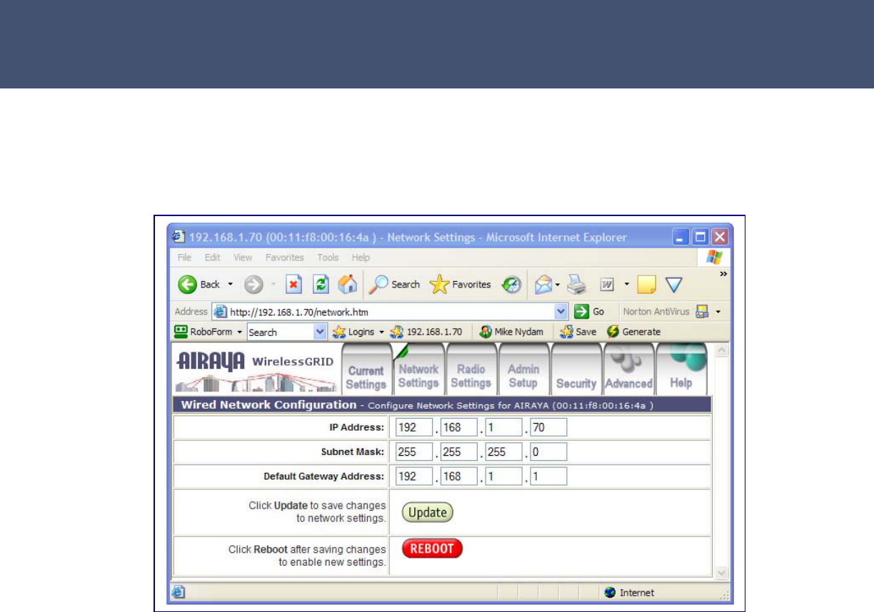
Network Settings Tab
The Network Settings screen is used to modify your wired network IP
Address, Subnet Mask, and Default Gateway Address.
The screen includes the following entries:
IP Address – The IP address of the bridge you are working with. The IP
address for each bridge must be unique; check with your network
administrator for the correct IP address assigned to this device. Default IP
address: 192.168.1.70.
Subnet Mask – The subnet mask allows networking software to
determine which parts of the IP address specify the network address and
which parts specify the host address. Default Subnet Mask:
255.255.255.0.
Default Gateway Address – IP packets destined for other subnets are
automatically sent to the default gateway, which routes the traffic to the
correct network. The gateway address must be specified following the
same convention as the IP address. Default Gateway Address:
192.168.1.1.

Airaya
- 23 -
Airaya Proven, Fast and Affordable Outdoor Wireless Bridges
TIP
If you want to return to the WirelessGRID-300 NMS after updating network
settings, enter the new IP address in your web browser and follow the log
in procedure.
Follow these steps to update network settings:
1. Update the IP Address.
2. Update the Subnet Mask.
3. Update the Gateway Address.
4. Press Update to save changes.
5. Press Reboot to cycle power and enable new network settings.
- 24 -
Airaya
WirelessGRID
-
300 Backhaul
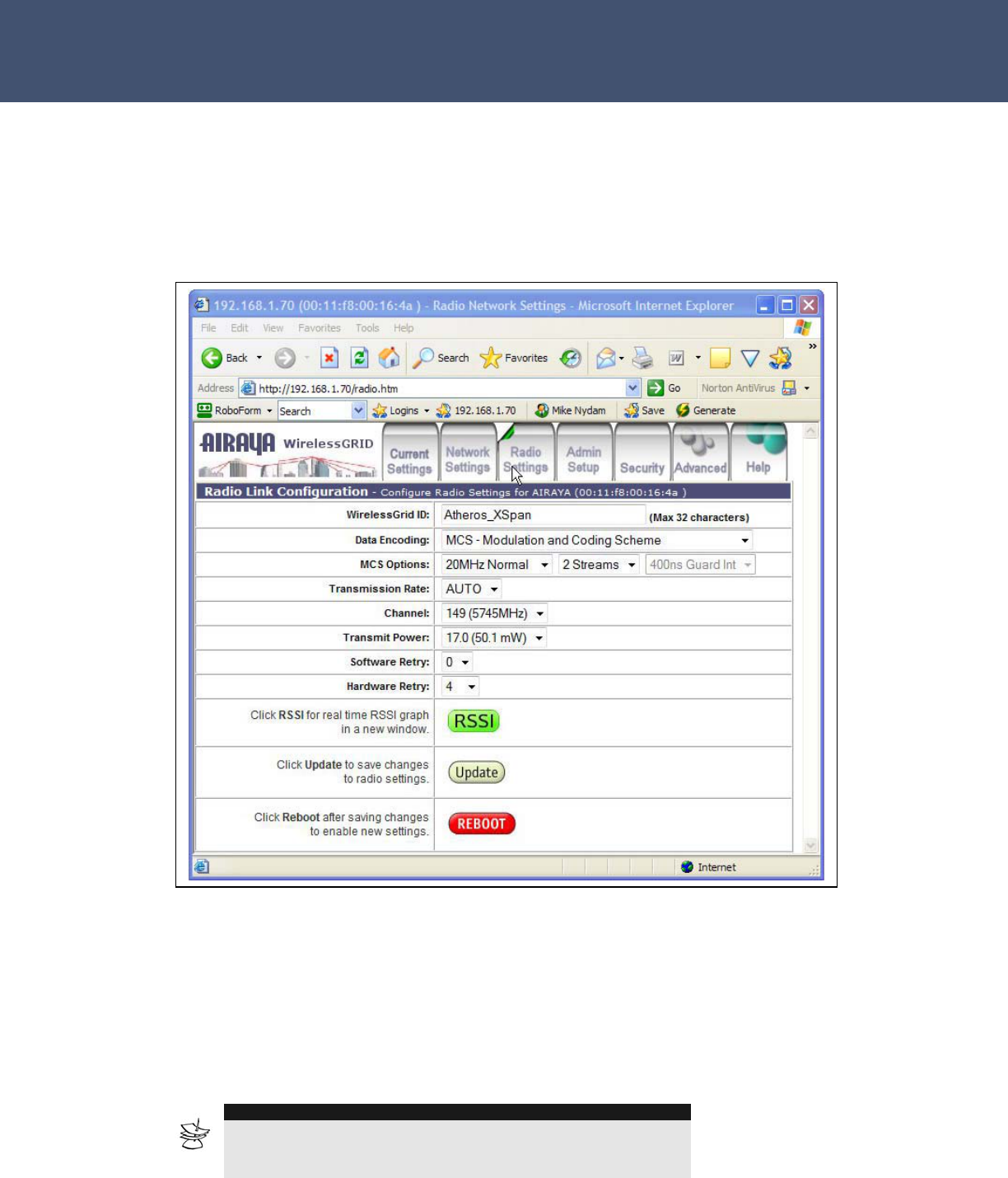
Radio Settings Tab
The Radio Settings screen is used to define the WirelessGRID-300 ID,
Country Code, Wireless Mode, Radio Frequency, Data Rate, and
Transmit Power settings of a bridge.
The following parameters can be modified on the Radio Settings screen:
WirelessGRID-300 ID – The WirelessGRID-300 ID provides a unique
network ID for each WirelessGRID-300 network. Enter a number or
address with up to 32 characters. Default WirelessGRID-300 ID: “AIRAYA
WirelessGRID-300 Network”
NOTE
WirelessGRID-300 radios do not use or broadcast SSID’s.
Sniffing programs do not have access to WirelessGRID-300
wireless networks.

Airaya
- 25 -
Airaya Proven, Fast and Affordable Outdoor Wireless Bridges
Data Encoding – Data encoding allows you to select the type of radio
transmission you would like to use. Changing Data Encoding will change
available MSC Options and available Data Streams, Radio Frequency
(center channels), and Data Rate options for your bridge.
Wireless Mode – Select the desired channel size for your AIRAYA
WirelessGRID-300 bridge. WirelessGRID-300 bridges are capable of
operating on 20 or 40 MHz wide channels.
NOTE
When you have finished updating the Wireless Mode, make sure to
press Update to view revised Radio Frequency, and Data Rate settings.
Radio Frequency – Select the desired frequency of operation from the
drop-down menu. The radio frequencies that appear are dependent on
the Country Code enabled and Wireless Mode specified.
Transmission Rate – Select the desired Transmission (Signaling) Rate
from the drop-down menu. The Transmission (Signaling) Rates that
appear are dependent on the Wireless Mode specified.
Transmit Power – Select the desired Transmit Power option from the
drop-down menu. This option is dependent on the Country Code and
Radio Frequency specified.
Follow these steps to update the radio network settings.
NOTE
You must press Update after each radio parameter change. Radio
parameters are interdependent, so each will change with every selection
you make.
1. Update the WirelessGRID-300 ID.
2. Select the MCS Mode
3. Select Wireless Mode
4. Select Radio Frequency
5. Select Data Rate
6. Select Transmit Output Power
7. Press Reboot to cycle power and enable new radio settings.
NOTE
All bridges in the WirelessGRID-300 network require the same MCS Mode,
WirelessGRID-300 ID, Wireless Mode, and Radio Frequency settings to
send and receive information correctly.
- 26 -
Airaya
WirelessGRID
-
300 Backhaul
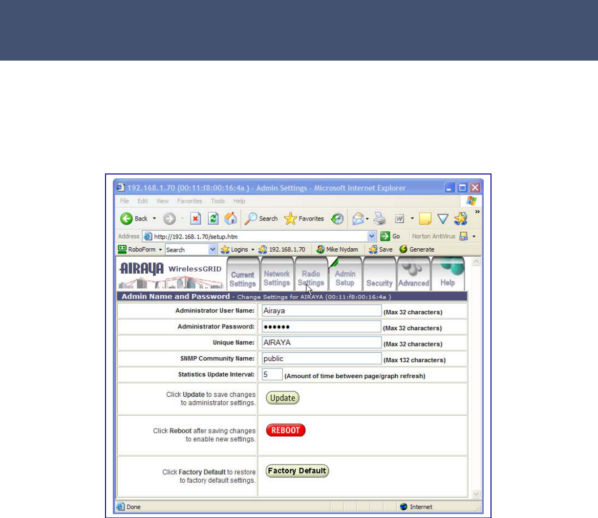
Admin Setup Tab
The Admin Setup screen is used to modify the Administrator User Name
and Password for the WirelessGRID-300 NMS, as well as the Unique
Name and Statistics Update Interval settings, described below:
Administrator User Name – Create a new user name by typing over
the contents of this field. Default Administrator User Name: Airaya.
Administrator Password – Create a new password by typing over the
contents of this field. Default Password: Airaya
Unique Name – A 32 character string used to identify the bridge. Default
Unique Name: AIRAYA (All capital letters.)
SNMP Community Name – SNMP string used by SNMP monitoring
programs to access the system. Default: public
Statistics Update Interval – This value sets the page refresh rate for
the remote bridge statistics screen and graph. Default interval: 5

Airaya
- 27 -
Airaya Proven, Fast and Affordable Outdoor Wireless Bridges
Factory Default button – This button clears all parameters and resets
the bridge to factory default settings.
Follow these steps to update administrator login settings:
1. Update the Administrator User Name.
2. Update the Administrator Password.
3. Write down your new login settings and keep them in a safe place for
future reference.
4. Press Update to save settings.
5. Press Reboot to cycle power and enable new settings.
Follow these steps to update Unique Name, SNMP Community Name,
and Statistics Update Interval settings:
1. Update the Unique Name.
2. Update the SNMP Community Name
3. Update the Statistics Update Interval value.
4. Press Update to save your new settings.
5. Press Reboot to cycle power and enable new settings.
Follow these steps to reset the bridge to factory defaults:
1. Press Factory Default button to reset bridge to AIRAYA default
settings.
2. When prompted, press Reset to restore default settings or Cancel to
keep current settings.
3. Press Reboot to cycle power and restore factory defaults.
SECURITY TIPS
To ensure that only authorized users gain access to the WirelessGRID-300
NMS, AIRAYA recommends that you change the Administrator User Name
and Password from their factory default settings.
When selecting a new password, do not use a term that can be easily
guessed, such as your name. Random combinations of numbers and
characters are much safer to use, though harder to remember.
- 28 -
Airaya
WirelessGRID
-
300 Backhaul
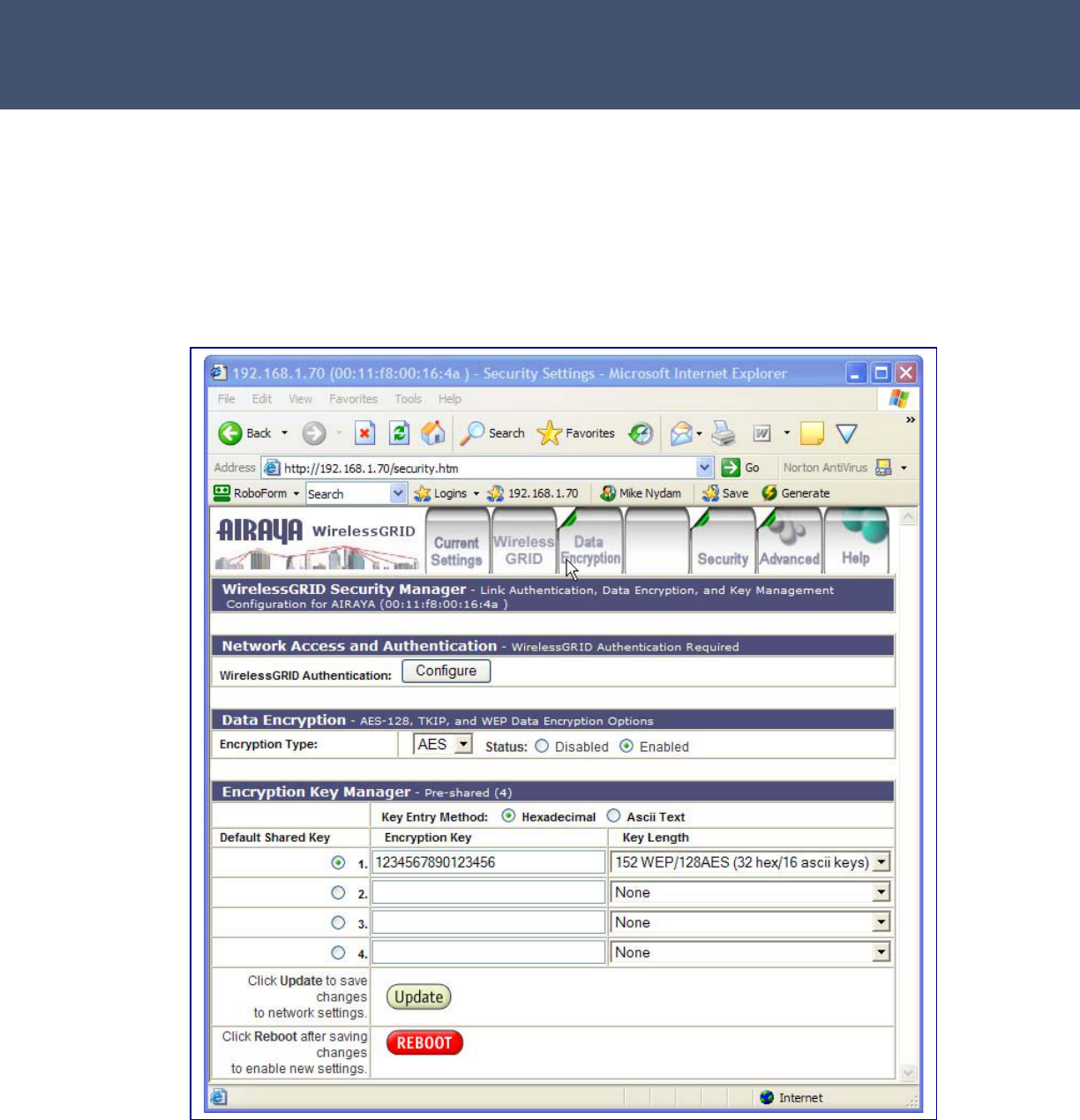
Security Tab – Data Encryption
The Security screen provides a link to the WirelessGRID-300 Authorized
Bridge List. All bridges in a WirelessGRID-300 network require entry into
the authorized Bridge list. This screen is also used to enter or update
data encryption settings for the bridge. The following sections describe
the entries of each area on this screen.
WirelessGRID-300 Authentication
Click Configure to add, edit, or delete bridge MAC addresses from the
authorized bridge list.

Airaya
- 29 -
Airaya Proven, Fast and Affordable Outdoor Wireless Bridges
Data Encryption
Encryption Type – WirelessGRID-300 bridges support AES data
encryption. Default Setting: Open (Not enabled).
128-bit AES – WirelessGRID-300 bridges support hardware-based
embedded 128-bit AES encryption. Enter 16 ascii or 32 hexadecimal
digits.
Status – The status button indicates the current state of encryption on
your bridge. Default: Disabled.
Disabled – No data encryption is enforced on your bridge.
Enabled – Data encryption is enforced on your bridge.
Follow these steps to enable Data Encryption on the bridge:
1. Select an Encryption Type (AES).
2. Change the Status to reflect the proper status.
3. Press Update to save settings.
4. Press Reboot to enable new security settings.
Encryption Key Manager
Pre-Shared Key Configuration – When you select Pre-Shared Key for
encryption, you may enter up to four default shared-keys in the
Encryption Key Manager. Please note: When encryption is enabled, all
bridges require an identical Key Entry Method, Encryption Key, and
Encryption Key Length.
Key Entry Method – You can use hexadecimal digits or ASCII text to
enter each key. Click on the "key length" drop-down menu to view
lengths for each type of key.
Default Shared Key – Select the default pre-shared key you want to
enable.
Encryption Key – Enter up to four pre-shared encryption keys.
Key Length – Specify the length of the pre-shared encryption keys.
NOTE
Refer to the section on the WirelessGRID-300 System Setup tab for
detailed instructions on how to add, edit, or delete bridge MAC addresses.

- 30 -
Airaya
WirelessGRID
-
300 Backhaul
Use the following steps to add a Pre-Shared Key to the Key Manager on
the main security screen:
1. Select a Key Entry Method (hexadecimal or ASCII text).
2. Select a Default Shared Key.
3. Enter up to four shared Encryption Keys.
4. Specify the Encryption Key Length based on the Encryption Key just
entered.
5. Press Update to save settings.
6. Press Reboot to enable new security settings.
Airaya
- 31 -
Airaya Proven, Fast and Affordable Outdoor Wireless Bridges
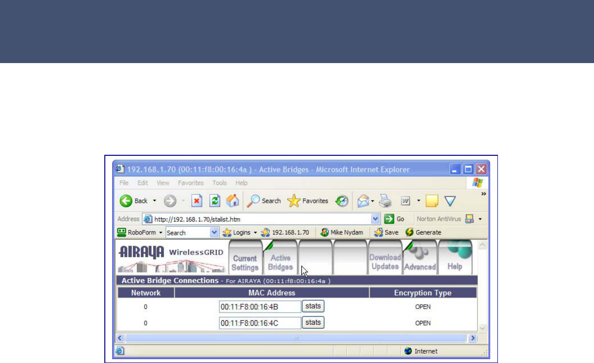
Active Bridge Status Tab
This screen is used to view the current status of all authorized remote
bridges for the (local) bridge that you are logged into.
This screen provides the following data:
Network – All remote bridges have a value of “0”.
MAC Address – MAC Address of each authorized remote bridge in
network.
Stats button – Displays the remote bridge statistics screen for the MAC
address you select. Press stats to open the remote bridge statistics
screen.
Encryption Type – Displays the current data encryption settings for
remote bridges
- 32 -
Airaya
WirelessGRID
-
300 Backhaul
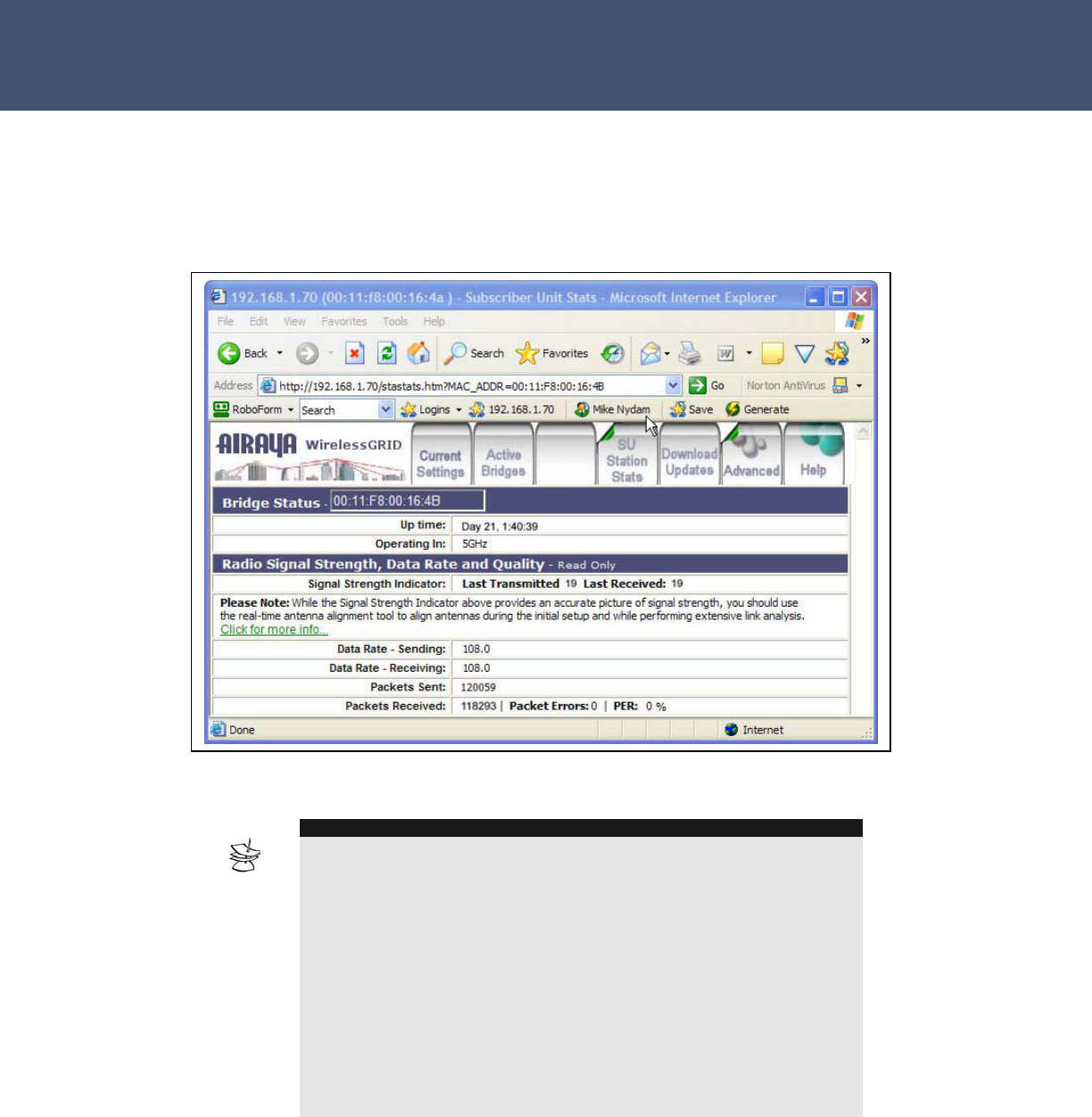
Remote Bridge (SU Station) Statistics Tab
This screen is used to view the current statistics of a remote bridge
communicating with the (local) bridge you are logged into.
This screen provides the following data:
Bridge Status
NOTE
Tip: To allow WirelessGRID-300 bridges to monitor their own signal
strength and packet error rates and dynamically adjust data rates, you
can set Data Rate on the Radio Settings tab to "Best". This will allow the
bridge to monitor signal strength on a packet-by-packet basis, adjusting
data rate accordingly. If signal strength is not optimum, the radio will
adapt and change to a lower modulation, which in turn lowers the radio
data rate, but provides a higher effective TCP/IP data rate by increasing
radio receiver sensitivity and reducing the packet error rate. This adaptive
data rate ability provides for better overall quality and reliability of the
link.
Tip: When running time sensitive applications such as VoIP and/or
VideoIP cameras, setting bridges to specific data rates reduces latency
and improves performance on these systems.

Airaya
- 33 -
Airaya Proven, Fast and Affordable Outdoor Wireless Bridges
Uptime. Elapsed time the bridge has been up and since the last power
cycle.
Operating In. Specifies the general frequency range remote bridge is
operating in.
Signal Strength, Radio rates, and Quality:
Signal Strength Indicator. Signal Strength is a good indicator of overall
network quality. Lower values (below 15) indicate a bridge will only be
able to communicate at low data rates. Higher signal strength values
(above 15) indicate the bridges have the ability to run at faster data
rates.
Last Transmitted. Signal Strength values (measured in dBm) for the last
packets transmitted. Signal Strength is a good indicator of how your link
will run. When “best” data rate is selected low values indicate the local and
remote bridges are operating in a slower mode.
Last Received. Signal Strength values (measured in dBm) for the last
packets received.
Data Rate - Sending. Displays the current radio data rate being used to
send data from the bridge you are attached to, to the remote bridge.
Data Rate - Receiving. Displays the current radio data rate being used to
receive data from the remote bridge.
Packets Sent. Indicates the total number of packets transmitted since the
bridge has been up.
Packets Received. Indicates the total number of packets received since
the bridge has been up.
Receive Packet Errors. Indicates the total number of receive packets
errors generated since the bridge has been up.
Receive Packet Error rate (PER). Percentage of receive packet errors to
packets received since the bridge has been up.
- 34 -
Airaya
WirelessGRID
-
300 Backhaul
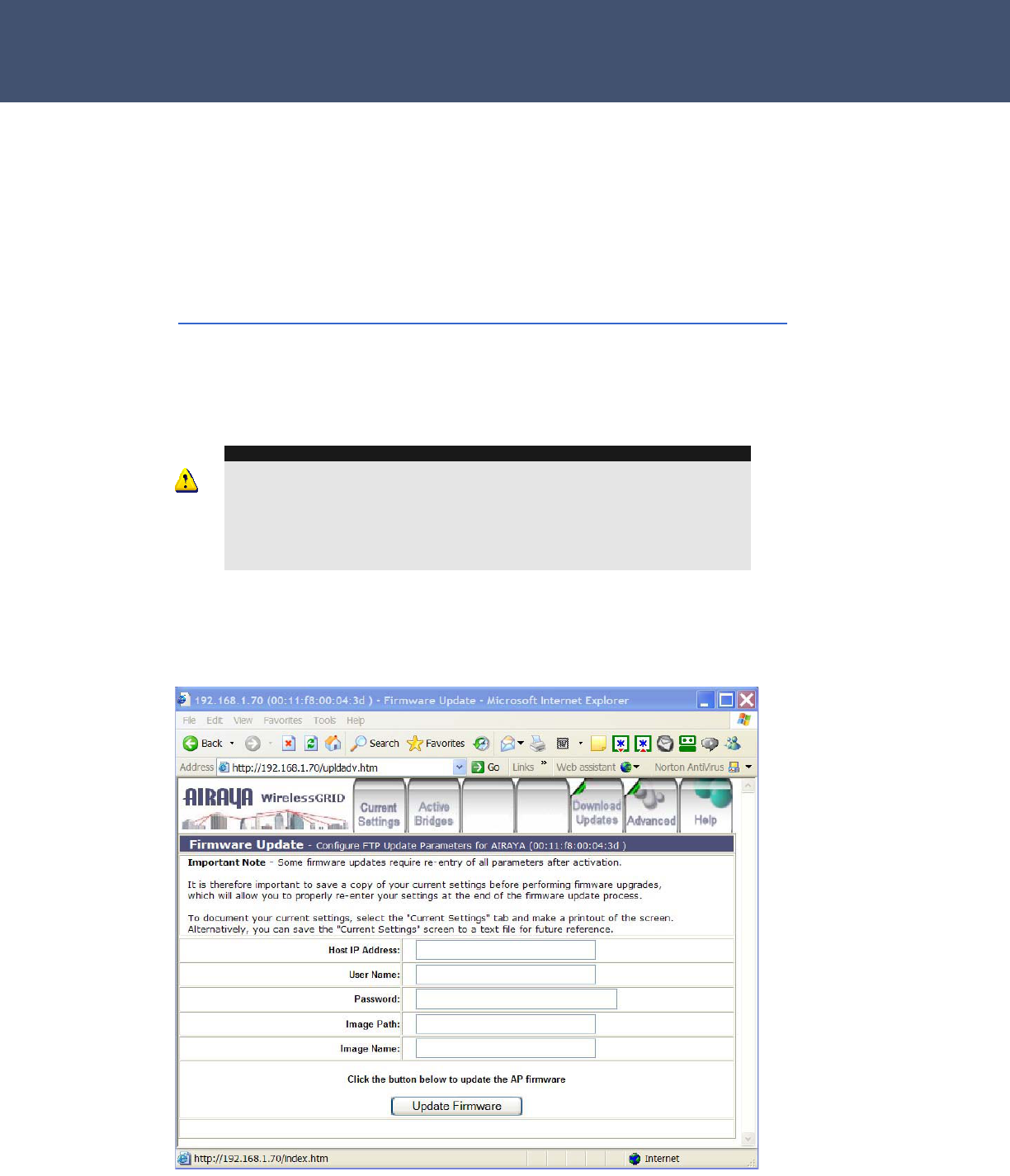
Firmware Update Tab
Periodically, AIRAYA releases firmware updates that fix known issues and
enhance the functionality of WirelessGRID-300 bridges. The latest
WirelessGRID-300 firmware release can be located in the support section
of the AIRAYA website at the following URL:
http://www.airaya.com/products/productdb/_product_support.asp
If you are unsure whether you need an upgrade, please contact AIRAYA
customer support (support@airaya.com) and a representative will help
you.
WARNING!
Some configuration parameters can be overwritten during the bridge
firmware upgrade process. As a safeguard, save a copy of your current
settings before performing the upgrade. This will allow you to re-enter your
settings if necessary. To document your settings, you can either select the
Current Settings tab and copy the screen to a text file or print the screen.
You should follow this procedure for each bridge that you plan to upgrade.
The following screen shows the settings used for upgrading bridge
firmware:

Airaya
- 35 -
Airaya Proven, Fast and Affordable Outdoor Wireless Bridges
Settings include:
Host Name – The IP address of FTP server where new firmware is
located.
User Name – Authorized User Name for accessing the FTP server.
Password – Valid Password for accessing the FTP server.
Image Path –Path to firmware image on the FTP server. If firmware
image is located in the root directory of your FTP server, leave this field
empty.
Image Name – Filename of firmware image.
Update Firmware –Button to start upload procedure for new firmware.
Follow these steps to update a bridge with new firmware image:
1. Enter the IP Address of your FTP server in the Host Name field.
2. Enter your authorized User Name for accessing the FTP Server in the
User Name field.
3. Enter your Password for accessing the FTP Server in the Password
field.
4. Enter a valid path to the firmware image on the FTP server in the
Image Path field. If firmware image is located in the root directory
of your FTP server, leave this field empty.
5. Enter the filename of the firmware image you are using to update the
bridge in the Image Name field.
6. Click on Update Firmware button to load new firmware image into
bridge.
7. Press Reboot to enable new key settings.
Help Tab
The AIRAYA online help system provides useful information about all
parameters and menus available in the WirelessGRID-300 NMS and
configuration utility. Select the Help tab on any screen and the
appropriate topics will appear in a pop-up style browser window.
- 36 -
Airaya
WirelessGRID
-
300 Backhaul
Appendix A – Bench Test Procedure
This WirelessGRID-300 bench test guide is designed to provide a new AIRAYA installer
with insight and understanding of how to setup, test and verify the functionality of a
WirelessGRID-300 link before performing a field installation. Utilities for testing network
communication, configuring bridges, aligning antennas, and measuring throughput are
discussed. Answers to common questions and troubleshooting tips are noted throughout
the document for your convenience.
While performing a bench test, antenna alignment is not critical as antennas are close
together and the signal strength (RSSi) utilities will always show a strong signal. As in all
field installations, bench tests should be performed with antennas correctly polarized,
either vertically or horizontally, and pointing at each other, at a distance of no less than
15 feet apart.
To obtain optimal throughput and link reliability, signal strength readings should be
above 18 for all bench tests. Very high signal strength values (RSSi above 50) are
common in bench tests and will not damage radios; however, measured TCP/IP
throughput results may be lower.
Bench test Procedure
Step 1. Setup a wired Ethernet network between test stations
1. Configure 2 test stations so that their network IP addresses are in the same range
and can communicate with each other via Ethernet. If you are not familiar with IP
addresses, please contact AIRAYA for the name of a qualified network installer in
your area.
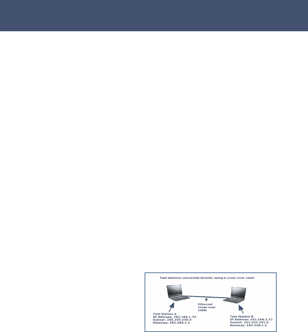
2. Verify your test network setup by using an Ethernet crossover cable directly
connected between the two test stations, or by connecting the 2 stations using a
switch, hub or router using straight-through Ethernet cables.
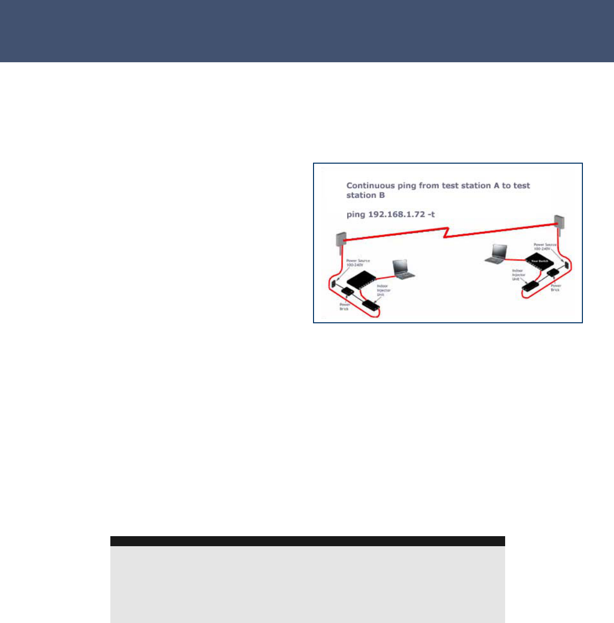
To verify your wired network setup is
working properly, run a continuous ping
between test stations A and B. To do
this, open a DOS or CMD window on
test station A, then type the following at
the command prompt: ping
192.168.1.72 –t and on station B,
type ping 192.168.1.73 -t Note: -t
runs a continuous ping.
Airaya
- 37 -
Airaya Proven, Fast and Affordable Outdoor Wireless Bridges
If you receive ping responses from both test stations, the network IP configuration and
physical wiring is working properly between the 2 test stations using Ethernet. If you
cannot ping both test stations, check your Ethernet cable connections and test station
network settings to verify they are configured properly.
When ping works properly with wired test stations, go to Step 2.
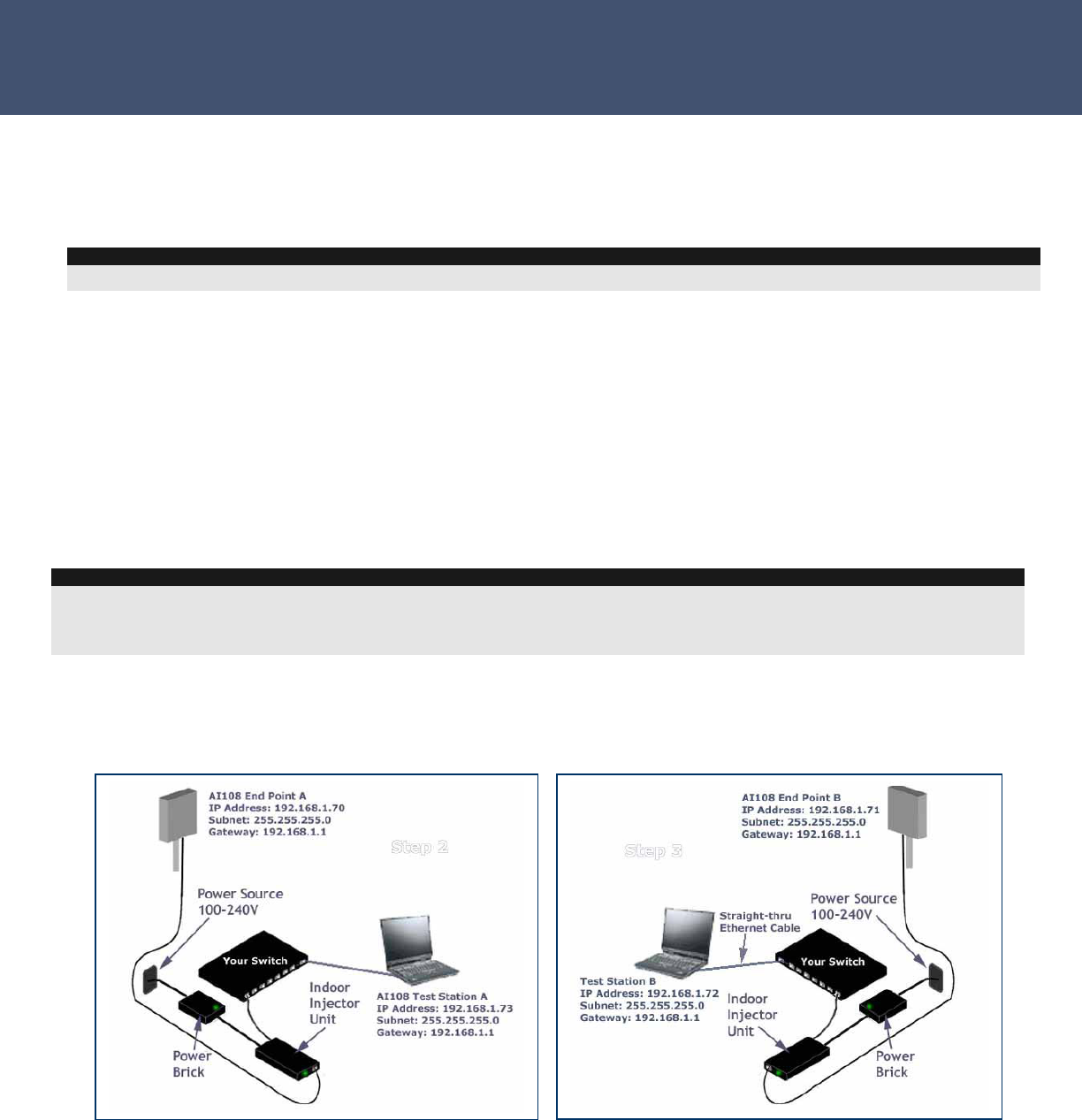
Step 2. Setup wired Ethernet network connections to bridges
Connect directly using straight-thru cables, or through network switches or routers using
straight-thru Ethernet cables.
Example IP Configuration of test stations and outdoor bridges with default
configuration parameters:
1. Start a continuous ping from test Station A to bridge end point A. To start a
continuous ping using the factory default IP settings of the bridge, type the
following into a DOS or CMD window on test station A:
NOTE
WirelessGRID products shipped as complete kits have one bridge factory-configured with IP address 192.168.1.70, and one
bridge factory-configured with IP address 192.168.1.71. Both bridges have a default subnet mask of 255.255.255.0
1000 Mbps full duplex (gigabit) ports are best from connecting bridges to wired Ethernet networks.
NOTE
If ping does not work between 2 wired test stations, it will not work between 2 test stations connected by a WirelessGRID link.

- 38 -
Airaya
WirelessGRID
-
300 Backhaul
Ping 192.168.1.70 –t (leave this ping window running so you can see ping
results easily)
2. If there is no response, try IP address 192.168.1.71, or cycle the power on
bridge end point A.
After ~45 seconds, you should see ping responses from 192.168.1.70 (bridge A). If you
see ping responses on test station A, you have an IP network connection between test
station A and bridge A.
If you can ping bridge A, you can open the HTTP configuration utility and network
management system (NMS) using a web browser. You will not be able to ping across the
link to bridge B until WirelessGRID-300 bridge list authorization entries are made in both
bridges. (See step 3)
3. Setup the Ethernet network connection between bridge B and test station B
using the same procedure described above, then verify that the test station B to
bridge B setup is correct.
After verifying that both bridges and their respective test stations can
communicate via Ethernet, go to step 3.
Step 3. Setup bridge software configuration for bridge
After verifying that both bridges and their respective test stations can communicate via
Ethernet, you will need to setup and verify bridge configuration so they will be able to
communicate over the radio link. The configuration given here will be a minimal
configuration for test purposes; for more detailed configuration information, please refer
to the product manual.
1. On each test station, open an http session by entering the bridge IP address
into the address field of your web browser. The correct format is:
http://192.168.1.70, or whatever the bridge’s IP address has been set to.
Note
Check that the Ethernet link light is on at test station A if connected directly to bridge A with
straight-thru cable, or on the switch/router port that bridge A is plugged into if connected
with a straight-though Ethernet cable.
If the Ethernet link li
g
ht is on and
y
ou cannot
p
in
g
brid
g
e A, then re-check IP address and
NOTE
Factory default administrative User Name and Password are Airaya with an uppercase A
As a security measure, the WirelessGRID http configuration utility and network management systems (NMS)
will timeout if left open with no activity for 3 or more minutes. You will need to re-login to again access the
utility.
Airaya
- 39 -
Airaya Proven, Fast and Affordable Outdoor Wireless Bridges
2. Login using the default Administrator name and password. Each test station
should now be displaying the “Current Settings” screen.
3. Record the IP address and MAC address of each bridge. You can also enter a
Unique Name under the Admin Setup tab to help in identifying bridges. It is
common to use this field to enter 32-character location identifiers.
Bridge IP Address MAC Address Unique Name
A
B
4. Under WirelessGRID-300 Bridge List, on bridge A, click “Add” and enter
bridge B’s MAC address in the “Bridge MAC Address” box, using the
xx:xx:xx:xx:xx:xx format. Click “Add New.”
5. On bridge B, use the same procedure above to add bridge A’s MAC address.
6. On the “Data Encryption” tab, make sure “Encryption Type” is disabled.
7. On each bridge, click on the “Reboot” button on either the Network Settings or
Radio Settings tab to enable new WirelessGRID-300 Bridge List settings.
8. On each bridge, reopen the http interface and verify that entries were correctly
saved by reviewing the “Current Settings” screen.
After verifying that both bridges have
the proper WirelessGRID-300 Bridge
List settings, go to step 4.
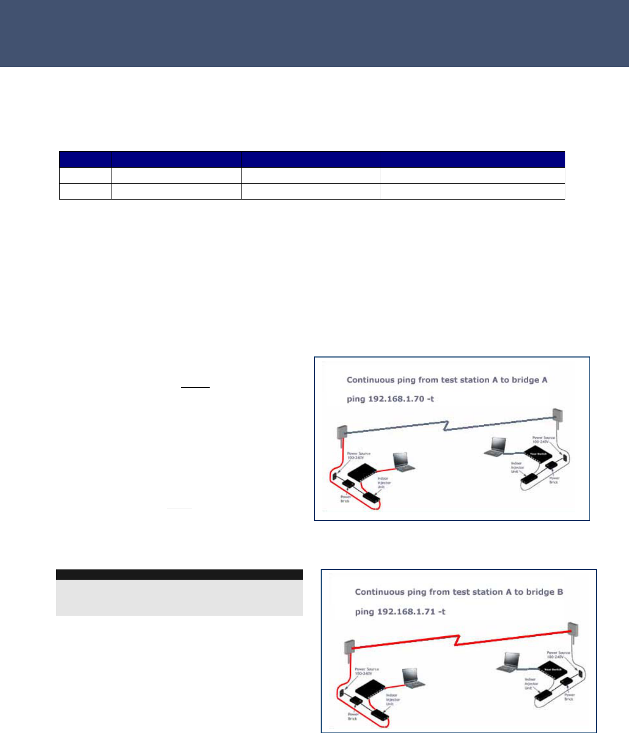
Step 4. Test network connectivity across
a WirelessGRID-300 link
After verifying that both bridges and their
respective test stations can communicate
via Ethernet, and confirming new WirelessGRID-300 bridge list entries were saved, the
following ping tests should be done.
To verify network connectivity across a
WirelessGRID-300 link, you should use test
station A to do the following:
Ping 192.168.1.70 -t to ping bridge A
Ping 192.168.1.71 -t to ping bridge B across
the wireless radio link
NOTE
After rebooting bridges, the radio link should be
established within one minute. If TPC and DFS are
enabled, this process may take up to two minutes.
Test
Station A
Test
Station B
Bridge A
Bridge B
- 40 -
Airaya
WirelessGRID
-
300 Backhaul
Ping 192.168.1.72 -t to ping test station B across the wireless link
If all ping tests are successful, then you have a properly configured WirelessGRID-300
link. Go to Step 5.
Troubleshooting tips for pinging across a
link:
If you do not get a ping across the two end
points from test station A to test station B;
You may have a power problem
- Verify that each bridge is connected
to a power source with the proper
input voltage.
You may have an Ethernet network cable
problem at one end
- Verify all physical connections. You should have an Ethernet link light on the
switch, router, or computer connected to each bridge.
You may have an http configuration error
- Verify the configurations of both bridges using the http NMS. Bridge A should
have an entry in its WirelessGRID-300 Bridge List for the MAC address of the
bridge B, and bridge B should have an entry in its WirelessGRID-300 Bridge List for
the MAC address of the bridge A - without correct MAC addresses (bridge
authorization) in each side of the link, the bridges will not communicate or let
traffic pass.
Step 4a. Check throughput of WirelessGRID-300 link (optional)
To check the throughput of a WirelessGRID-300 link, use an FTP program or some other
type of throughput measuring utility to check the speed of your link. If you don’t know
what program to use to test link throughput, AIRAYA can provide you with a traffic
generating program and shareware throughput monitoring utility at no charge. A link to
NOTE
When doing a Multipoint bench test, it is best to setup the base station as bridge A, and
the first subscriber unit as bridge B using the procedure in Step 3. To test additional
subscriber units, use this procedure for each new subscriber unit, repeating the ping test for
bridge B one at a time. Use different IP addresses for each new subscriber units. (E.g. Ping
192.168.1.74 -t for subscriber two, and so on) This will simplify diagnostics. Once all
subscriber units (SU) respond to this test and you have verified that each subscriber has a
different IP address, you can power up all SU’s and each one should be ping-able.
Test
Station A
Test
Station B
Bridge A
Bridge B
Test
Station B
Bridge A
Bridge B
Test
Station A

Airaya
- 41 -
Airaya Proven, Fast and Affordable Outdoor Wireless Bridges
these utilities can be found on the main page of the AIRAYA support section of website.
http://www.airaya.com/products/productdb/_product_support.asp
If you are planning to do meaningful throughput tests, you will need a minimum of 2 test
stations with at least 1.6GHz processors and Windows XP, 2000, or the Linux operating
system. Windows 95, 98, ME TCP/IP stacks limit TCP throughput and cannot be used to
accurately test throughput on an AIRAYA WirelessGRID-300 link.
AIRAYA’s internal bench test results can be found at the following web address:
http://www.airaya.com/products/WirelessGRID-300_testdata.html
NOTE
If you use 100/10 Mbps Ethernet to communicate with a WirelessGRID bridge, you will not get
maximum throughput, and packet errors may occur between the bridge and your 100/10 Mbps
Ethernet device. AIRAYA recommends 1000 Mbps Ethernet switches or routers to maximize
throughput. Throughput tests will not work if Step 4 above has not been finished successfully.

- 42 -
Airaya
WirelessGRID
-
300 Backhaul
Step 5. Field deployment of WirelessGRID-300 bridges
It is a good idea for you to become familiar with the product before installing it for the
first time. AIRAYA recommends you perform a bench test before deploying any units to
the field.
The bench test and verification process can also be performed in the field, but it is
generally much easier to configure the units on the bench before setting them up in the
field.
Changes in field-deployed bridges include but are not limited to the following:
1. IP Addresses to match your network
2. Change the administrative user name and password to prevent un-authorized
access the administrative interfaces
3. Location-specific unique names entries to help in identifying units in the field
4. Encryption enabled if you want your data encrypted as it travels across your new
WirelessGRID-300 system.
Airaya
- 43 -
Airaya Proven, Fast and Affordable Outdoor Wireless Bridges
Appendix A: Weatherproofing RF Cable Connections
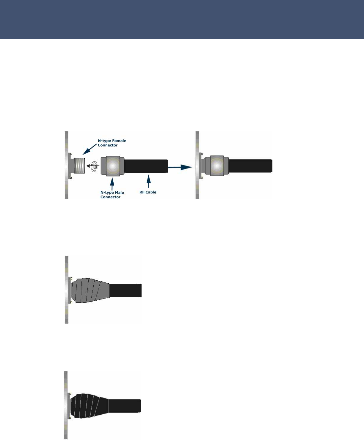
Step 1. Connecting Cable Assembly to Antenna or Enclosure
Attach RF cable assembly to antenna/enclosure by fastening the N-type male
connector to the N-type female connector. Notes: Ensure both connectors are
clean and dry. Hand-tighten firmly.
Step 2. Sealing the Connector Assembly
Tightly wrap the connectors with 2 layers of rubber tape (butyl). Notes: Rubber
tape should seal entire connection and extend 1 inch beyond antenna
connector/cable assembly. 3M 3339 tape works very well in this application.
Step 3. Covering Rubber Tape with Electrical Tape
Tightly wrap the rubber tape with 2 layers of electrical tape. Note: Electrical
tape should extend 1 inch beyond rubber tape to ensure full coverage.

- 44 -
Airaya
WirelessGRID
-
300 Backhaul
How to Get Help
AIRAYA offers several customer support options to assist you with
difficulties you might experience with your WirelessGRID-300 wireless
bridge:
Worldwide Web Support
The AIRAYA web site (www.airaya.com) provides quick and easy answers
to common technical questions. You’ll find a complete Knowledgebase, a
variety of technical documents, product manuals and literature, and other
helpful information. Most materials can be found in the support area.
Contacting AIRAYA
Contact your AIRAYA distributor or dealer before you call AIRAYA. They
are familiar with your needs and will generally be able to provide you with
the fastest and most comprehensive support. If they are unavailable or
unable to answer your questions, then contact AIRAYA directly by one of
the methods listed below.
Before contacting our technical support team, please create a copy of the
“Current Settings” tab using your web browser and the instructions in this
manual. If you are not able to run the web-based configuration utility,
then write down any error messages you see on-screen and contact
AIRAYA at the appropriate support number list above.
AIRAYA Contacts
Phone (866) 224-7292 (U.S.)
(408) 776-2846 (international)
Skype AIRAYA_Support
Fax (408) 776-3339
E-mail support@airaya.com
Web site www.airaya.com
IMPORTANT NOTE
Free support is only available to registered users. Register via the AIRAYA
web site (www.airaya.com) in the support section. Support is available 24
hours a day.