Alcatel USA 8505U-16 Digitally Modulated Radio User Manual 01 General
Alcatel USA Marketing, Inc. Digitally Modulated Radio 01 General
Contents
- 1. General
- 2. Initial Turnup
General

3DH03220 MDR-8000 Series Radios
Issue 6, April 2002
1-1
Page
section
1
general
List of Paragraphs
1.1 INTRODUCTION......................................................................................1-3
1.2 STANDARD FEATURES .............................................................................1-3
1.3 NAMING CONVENTION ........................................................................1-5
1.4 ORDERING INFORMATION......................................................................1-6
1.5 SYSTEM CONFIGURATIONS ....................................................................1-6
1.6 RADIO CONFIGURATIONS ......................................................................1-6
1.6.1 Basic Configurations.................................................................................1-6
1.6.2 Ring .......................................................................................................1-7
1.6.3 Space Diversity Add-On............................................................................1-7
1.6.4 Optical 2 X 4 Configuration ......................................................................1-7
1.7 FEATURES AND OPTIONS........................................................................1-7
1.7.1 Primary Power .........................................................................................1-7
1.7.2 Transmit Power Level Options ....................................................................1-7
1.7.3 Differential Absolute Delay Equalization (DADE) ..........................................1-7
1.7.4 Trellis Encoding and Time Domain Equalization (TDE)...................................1-7
1.7.5 MCS-11 Alarm/Control Interface ...............................................................1-7
1.7.6 Foreign Alarm Interface.............................................................................1-8
1.7.7 Relay Interface Option..............................................................................1-8
1.7.8 Extended Link Monitor Channel..................................................................1-8
1.7.9 Automatic Transmitter Power Control Provisioning Option..............................1-8
1.7.10 Service Channels Provisioning Options .......................................................1-8
1.7.11 Mechanical Options ...............................................................................1-10
1.7.12 Capacity upgrade..................................................................................1-12
1.7.13 Bandwidth upgrade................................................................................1-12
1.8 USER SYSTEM INTERFACE (USI) ..............................................................1-12
1.8.1 System Security......................................................................................1-12
1.9 RADIO CHARACTERISTICS......................................................................1-13
3DH03220 MDR-8000 Series Radios
Issue 6, April 2002
1-2
Page
1.10 EXTERNAL INTERFACE REQUIREMENTS...................................................1-32
1.11 EQUIPMENT LISTING .............................................................................1-35
1.11.1 Diplexer Filter Kits ..................................................................................1-45
1.11.2 Standard Filter Kits .................................................................................1-45
1.11.3 Cable Drop Kit Option............................................................................1-45
1.12 FAN ASSEMBLY.....................................................................................1-45
1.13 HANDSET KIT........................................................................................1-47
List of Tables
Table 1-1 Rack Options.........................................................................................1-11
Table 1-2 Software ...............................................................................................1-13
Table 1-3 Guidelines.............................................................................................1-13
Table 1-4 Physical, Environmental, and Electrical Characteristics................................1-14
Table 1-5 OSS External Interface Requirements ........................................................1-32
Table 1-6 MDR-8000/i/s Common Shelf Assembly ..................................................1-35
Table 1-7 Supplied and Optional Equipment............................................................1-38
Table 1-8 I/O Interface Options.............................................................................1-40
Table 1-9 XMTR Options .......................................................................................1-41
Table 1-10 PA Options............................................................................................1-42
Table 1-11 RCVR Options........................................................................................1-43
Table 1-12 Capacity Keys for Transmitter and Receiver Modules ..................................1-44
Table 1-13 LBO Options..........................................................................................1-45
List of Figures
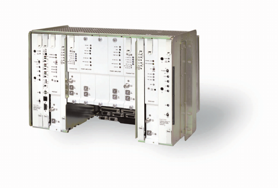
Figure 1-1 Typical MDR-8000/i/s/u Series Microwave Digital Radio ............................1-4
Figure 1-2 Typical MDR-8000/i/s/u Component Locations and Options......................1-36
Figure 1-3 MDR-8000/i/s Component Locations, Rear View.......................................1-37
Figure 1-4 Fan Assembly ........................................................................................1-46
Table 1-14 Fan Assembly/Lap Top Tray Options........................................................1-46
Figure 1-5 Fan Assembly With Laptop Tray Fully Extended..........................................1-47
Figure 1-6 Handset Kit ...........................................................................................1-48
3DH03220 MDR-8000 Series Radios
Issue 6, July 2002 General
1-3
1
GENERAL
1.1
INTRODUCTION
The MDR-8000/i/s/u series Microwave Digital Radios (see Figure 1-1) consists of:
•Solid-state, licensed, digital radios that provide transport for DS1, E1, and DS3 in
2, 6, 7, 8, 10, and 11 GHz RF frequency bands and OC3 in 6, 7, 8, 10, and 11 GHz
RF frequency bands
• Solid-state, unlicensed digital radios that provide transport for DS1 and DS3 in
the 5 GHz RF frequency band.
The following capacities and modulation schemes are available:
• MDR-8000 – 2, 4, 8, 12, or 16 North American Standard DS1 channels at either
32 or 128 TCM or 1 or 3 North American Standard DS3 channels with 1 or 3 way-
side DS1 channels at 64 QAM
• MDR-8000i – 2, 4, 8, 12, or 16 CCITT E1 channels at either 32 or 128 TCM
• MDR-8000s – 3 North American Standard STS1 channels with 3 wayside DS1
channels at 128 TCM
•MDR-8000u – 2, 4, 8, or 16 North American Standard DS1 channels at 32 TCM or
1 North American Standard DS3 channel with 1 wayside DS1 channel at 16 or 64
QAM.
The radio fits into a standard 19 in. (483 mm) rack and occupies seven vertical rack
increments. Up to four fully-equipped hot-standby radios can be mounted in a stan-
dard 7 ft. rack. The radio is front accessible and can be mounted against a wall or
back-to-back against other equipment.
1.2
STANDARD FEATURES
Standard features include:
•Frequency bands from 2 to 11 GHz
• Committee of European Post and Telegraph (CEPT)/Federal Communications
Commission (FCC) applications
• DS1, E1, DS3, and OC3 Traffic capacities.
• International Telecommunications Union (ITU)/ETSI/FCC compliant
•Five configuration options
• Upstream management compatibility
MDR-8000 Series Radios 3DH03220
General Issue 6, July 2002
1-4
• User-friendly Personal Computer (PC) monitor and control
• Automatic Transmitter Power Control (ATPC)
• Adaptive Time Domain Equalization (TDE)
• Extended Link Monitor Channel (ELMC)
• MCS-11/Telemetry Byte Oriented Serial (TBOS) Alarm/Control Interface
• Two independent PCM audio channels
Figure 1-1 Typical MDR-8000/i/s/u Series Microwave Digital Radio
3DH03220 MDR-8000 Series Radios
Issue 6, July 2002 General
1-5
1.3
NAMING CONVENTION
The MDR-8000/i/s/u series radio naming conventions are as follows:
MDR-8XXXi/s-XXX
i = INTERNATIONAL DATA RATE
s = SONET
u = UNLICENSED
GENERATION
MODEM OPTION: 4 = 16 QAM
5 = 32 TCM
6 = 64 QAM
7 = 128 TCM
LMW-3121
07/07/02
LINE CAPACITY: 2 = 2 DS1/E1s
4 = 4 DS1/E1s
8 = 8 DS1/E1s
12 = 12 DS1/E1s
16 = 16 DS1/E1s
45 = 1 DS3
135 = 3 DS3
155 = 3 STS1
FREQUENCY BAND: 02 = 2 GHz
05 = 5 GHz
06 = 6 GHz
07 = 7 GHz
08 = 8 GHz
10 = 10 GHz
11 = 11 GHz
MDR-8000 Series Radios 3DH03220
General Issue 6, July 2002
1-6
1.4
ORDERING INFORMATION
The radio is shipped as a complete unit; therefore, ordering information must specify
the following:
• System capacity:
•2, 4, 8, 12, or 16 DS1
•2, 4, 8, 12, or 16 E1
•1 or 3 DS3 with/without wayside DS1
• OC3 with/without wayside DS1
• System configuration: non-standby, non-standby/space diversity, hot-standby, hot-
standby/space diversity, frequency diversity
• Transmit and receive frequency
• Transmit power level
•Fault alarm requirements
• Service channel requirements
• DS1/E1 interface connector requirements
• Alarm interface connector requirements
1.5
SYSTEM CONFIGURATIONS
The MDR-8000/i/s radio can be provisioned as a terminal, synchronous repeater, ring
terminal, or ring repeater.
1.6
RADIO CONFIGURATIONS
1.6.1
Basic Configurations
The MDR-8000/i/s/u supports the three basic configurations:
• Non-standby – available in all frequency bands – stand alone transmit-
ter/receiver combination
•Hot-standby – available in all frequency bands except 5 GHz (unlicensed)
– pair of transmitters and receivers, both pairs operating on the same set
of go and return frequencies.
•Frequency diversity – available in all frequency bands except 2 GHz and
5 GHz (unlicensed) – pair of transmitters and receivers, each pair operat-
ing on a different set of go and return frequencies.
3DH03220 MDR-8000 Series Radios
Issue 6, July 2002 General
1-7
1.6.2
Ring
Non-standby radios are typically used in ring systems where the radios are
protected by the ring architecture.
1.6.3
Space Diversity Add-On
Space diversity can be added to any of the three basic configurations and
ring systems.
1.6.4
Optical 2 X 4 Configuration
Hot-standby and frequency diversity configuration are available with 2-fiber
or 4-fiber optical interfaces.
1.7
FEATURES AND OPTIONS
Features and options for the MDR-8000/i/s/u series of microwave digital radios are
described in the following paragraphs.
1.7.1
Primary Power
The MDR-8000/i/s/u series radios operate from 20.5 to 60 V dc primary
power with positive or negative ground.
1.7.2
Transmit Power Level Options
The standard radio is provided without a power amplifier (PA) module for
low-power applications. The optional PA module is available for high-power
requirements. There are different levels for the different frequency bands.
Refer to the electrical characteristics table in this section for specific levels.
1.7.3
Differential Absolute Delay Equalization (DADE)
DADEing adjusts the differential absolute delay between the main and
diversity signals in a space diversity configuration. DADEing is an auto-
matic function within the DS1/E1 and OC3 MDR-8000/i/s/u receivers, reduc-
ing the time required for initial turn-up and test.
1.7.4
Trellis Encoding and Time Domain Equalization (TDE)
Trellis encoding (DS1/E1/OC3) ensures that even with the most severe
multipath, only the correct digital data is demodulated. TDE further reduces
the disruptive effects of multipath distortion.
1.7.5
MCS-11 Alarm/Control Interface
MCS-11 is standard in the MDR-8000. The MDR-8000 can interface with
any alarm system that is based on the MCS-11 protocol. Use with the
TSM-2500 network management system to develop a central access point to
monitor and control the transmission system

MDR-8000 Series Radios 3DH03220
General Issue 6, July 2002
1-8
1.7.6
Foreign Alarm Interface
This provisioning option provides serial alarm/status reporting for the
Telemetry Byte Oriented Serial (TBOS) protocol. A wire-wrap adapter is pro-
vided to mate to connector J305 on the backplane.
1.7.7
Relay Interface Option
The optional AE-27AF Relay Interface unit provides relay closure indica-
tions of radio alarms and status. The relay interface also provides up to 16
station alarm inputs and six relay closure control outputs.
1.7.8
Extended Link Monitor Channel
ELMC is standard and performance monitoring, alarm and status informa-
tion, and remote controls are accessible through the ELMC channel, inde-
pendent of network management interfaces.
Optional remote provisioning and downloading capability is provided via an
ELMC option key that is mounted on the controller module.
1.7.9
Automatic Transmitter Power Control Provisioning Option
Automatic Transmitter Power Control (ATPC) is a standard feature that can
be enabled or disabled using the USI provisioning screens. When ATPC is
disabled, transmitter power is fixed at the recommended maximum level.
When ATPC is enabled, transmitter power may be reduced up to 10 dB from
the maximum power level when the far end RSL is above a minimum level.
When ATPC is enabled with timeout, transmitter ATPC activity is limited to
a maximum time without returning to minimum transmit power. After five
minutes of activity, the transmit power is forced to minimum until the far
end RSL returns to normal levels.
1.7.10
Service Channels Provisioning Options
The MDR-8000 provides a 256 kb/s auxiliary channel for servicing the radio.
This is an overhead channel and is independent of the traffic channels. The
256 kb/s service channel contains four 64 kb/s service channels. Three of the
four 64 kb/s channels (Service Channel 1, 2, and 3) can be provisioned on the
USI for a specific use. Service channel 4 is dedicated to radio commands and
ELMC. Service channel 4 is not provisionable. Only 16 kb/s out of the 64 kb/
s in this channel are used.
Service channels at both ends of a hop (and end-to-end in a link)
must be provisioned the same.
Note
3DH03220 MDR-8000 Series Radios
Issue 6, July 2002 General
1-9
Service channel provisioning is interactive. When an option is selected for
any service channel, that option is excluded from selections on the other
applicable service channels. Provisioning options for Service Channels 1, 2,
and 3 are listed:
• Service Channel 1 (64 kb/s channel) – can be used to carry 4-wire audio, RS232
data, or MCS-11 fault alarm information.
•AUDIO 1 and 2 – Two audio provisioning options (AUDIO 1 and
AUDIO 2) are provided for Service Channel 1. Each audio channel is
a 4-wire audio channel that provides off-hook detection, level control, and
E and M-lead signaling. AUDIO 1 also has DTMF decoding that allows a
specific station to be dialed. External connection to AUDIO 1 is J316.
External connection to AUDIO 2 is J317.
• RS232 1 – RS232 Channel 1 is an RS232 formatted data channel that
can provide interface to an external computer/modem. External connec-
tion to RS232-1 is J312.
•MCS-11 – The MCS-11 channel is an RS422 formatted data that provides
an interface to an external MCS-11 Monitor Control System or TSM sys-
tem, used to control multiple MCS-11 systems. External connections to
the MCS-11 include J307, J308, J309 and J310.
• Service channel 2 (64 kb/s channel) - can be used to carry 4-wire audio, RS232
data, or MCS-11 fault alarm information.
•AUDIO-1 and -2 – Same as Service Channel 1
• RS232-2 – RS232 Channel 2 is an RS232 formatted data channel that
can provide interface to an external computer/modem. External connec-
tion to RS232-1 is J313.
• MCS-11 – Same as Service Channel 1.
• Service Channel 3 (64 kb/s channel) - can be used to carry 4-wire audio, or MCS-
11 fault alarm information.
•AUDIO 1 and 2 – Same as Service Channel 1
• MCS-11 – Same as Service Channel 1.

MDR-8000 Series Radios 3DH03220
General Issue 6, July 2002
1-10
1.7.11
Mechanical Options
Mechanical options include:
• Racks. Refer to Table 1-1 for characteristics.
• Shelf covers - One front cover is provided.
• Rack extension kit PN 690-1125-001 through 005 - Extends 7-ft racks
PN 690-1124-XXX and 694-9000-XXX to any height from 7 ft 3-1/2 in. to
11 ft 6 in. The purpose of the extensions is to provide top support mount-
ing above the 7-ft level.
• Adjacent rack attachment (without/with rack extension) kit PN 694-
9004-001/002 – Provides hardware for bolting two rack assemblies (PN
694-9000-XXX) together. The -001 kit is used to tie two racks together
that do not have the optional rack extension kit (PN 690-1125-003)
installed. Kit -002 is used when the two racks have the optional rack
extension kit.
Guardrails and AC outlets are field installed and are sent in
shipper kits.
• Guardrail kit PN 690-4367-005 through -008 - Protects front only (PN
690-4367-007), front and rear (PN 690-4367-008), or sides (690-4367-005
and -006) of all configurations of rack PN 690-1124-XXX.
• AC outlet kit PN 690-4373-001 - Provides hardware for mounting ac out-
let to the guardrail (PN 690-4367-XXX).
• Optical Fiber Management Panel (OC3 only). Optical fiber management
panels are available for 2 or 4 fiber and for 2- or 4-fiber switched configu-
rations. Each optical fiber management panel supports two MDR-8000s
radio shelves. The 2- or 4-fiber switched optical fiber management panel
(PN 3EM09257AA) is used with splitter/combiners to support 2 or 4 fiber
switched applications using multimode or single mode fibers. For non-
switched applications, the 2 or 4 fiber optical fiber management panel
(PN 3EM09257AB) is used to support 2 or 4 fiber configurations.
Note

3DH03220 MDR-8000 Series Radios
Issue 6, July 2002 General
1-11
Table 1-1 Rack Options
PART NO. DESCRIPTION RACK TYPE
694-9000-001 19-in. wide by 7-ft. high aluminum rack, no top support bar,
no side covers
Standard
694-9000-002 19-in. wide by 7-ft. high aluminum rack with top support bar
(694-9001-002), no side covers
Standard
694-9000-003 19 in. wide by 6-ft high aluminum rack with top support bar
(694-9001-001), no side covers
Standard
019-0429-010 19-in. wide by 7-ft. high steel rack Seismic *
019-0429-020 19-in. wide by 9-ft. high steel rack Seismic *
019-0429-030 19-in. wide by11-ft. 6-in high steel rack Seismic *
019-0429-040 19-in wide by 11-ft. 8-in high steel rack Seismic *
019-0429-080 19 in.wide by 7-ft. 6-in high steel rack Seismic *
019-0429-090 19 in wide by 8-ft. high steel rack Seismic *
695-0905-002 23-in. wide by 7-ft. high aluminum rack, no top support bar,
no side covers
Standard
694-8873-001 MDR-8000 shelf mounting bracket extender
(for mounting 19-in. shelf in 23-in. rack)
694-8873-005 PDU mounting bracket extender
(for mounting 19-in. PDU in 23-in. rack)
690-1125-003 Aluminum rack extension (extends height of 7-ft aluminum rack)
694-9004-001 Adjacent rack attachment (without rack extension 690-1125-003)
694-9004-002 Adjacent rack attachment (with rack extension 690-1125-003)
690-4367-005 Short side guard rail
690-4367-006 Long side guard rail
690-4367-007 Guard rail (front only)
690-4367-008 Guard rail (front and rear)
690-4373-001 AC outlet
* Seismic racks require Seismic Accessory Kit PN 695-1001-001

MDR-8000 Series Radios 3DH03220
General Issue 6, July 2002
1-12
1.7.12
Capacity upgrade
The number of maximum DS1/E1 lines can be changed to any number
between 1 and 16 to meet expanding system needs. DS3 lines can be
expanded from 1 to 3. The number of available DS1/E1/DS3 lines is deter-
mined by printed circuit boards (capacity keys). Identical capacity keys plug
onto the transmitter and receiver modules. Changing the number of DS1/E1/
DS3 lines requires changing capacity keys. DS1 to DS1 and/or DS3 to DS3
capacity upgrades can be performed in-service on protected systems without
traffic interruption. In non-protected radios, traffic will be interrupted for
the duration of the procedure.
1.7.13
Bandwidth upgrade
Assuming no frequency or band change, DS1 to DS3 conversion can be
accomplished by changing out the I/O interface modules, LBO board, and
capacity keys and installing DS3 software. Electrical DS3 to optical OC3
conversion can be accomplished by changing out the I/O interface modules,
exchanging the LBO board with the auxiliary board, and changing capacity
keys and installing OC3 software. Changing out the LBO or AUX board
requires interrupting traffic for the duration of the procedure.
1.8
USER SYSTEM INTERFACE (USI)
A personal computer (PC) is required to access provisioning, status and alarm infor-
mation, and maintenance control functions (on-line maintenance and troubleshoot-
ing) within the radio. The PC is not supplied with the radio and must be provided by
the user. These functions are performed via the Alcatel USI maintenance program
software (Table 1-2). The PC must be IBM compatible. PC guidelines are addressed
in Table 1-3.
The USI runs on Windows 95
®
, 98
®
, NT
®
‚ or 2000
®
‚
1.8.1
System Security
Password options ensure that only authorized users have access to USI pro-
visioning screens. The level of security provided by the system depends on
how thoroughly the security system scheme is implemented and maintained
by the system administrator.
Note
3DH03220 MDR-8000 Series Radios
Issue 6, July 2002 General
1-13
1.9
RADIO CHARACTERISTICS
Refer to Table 1-4 for the physical, environmental, and electrical characteristics of
the MDR-8000/i/s/u series radio.
Table 1-2 Software
CD ROM PART NUMBER
DS1/E1 695-9406-021
DS3 695-9406-022
OC3 695-9406-023
Table 1-3 PC Guidelines
ITEM MINIMUM REQUIREMENTS
CPU Pentium
Speed 100 MHz or greater
RAM 32 Mbytes, minimum
Graphics VGA
Display Color
Hard Disk Required
Free Disk Space 100 Mbytes
CD ROM Drive Required
Mouse Optional
Operating System Windows 95, 98, NT, or 2000
Serial Port 2400 b/s

MDR-8000 Series Radios 3DH03220
General Issue 6, July 2002
1-14
Table 1-4 Physical, Environmental, and Electrical Characteristics
ITEM CHARACTERISTICS
PHYSICAL CHARACTERISTICS
Dimensions WIDTH DEPTH HEIGHT
483 mm (19 in.) 406.4 mm (16.25 in.) 311.15 mm (12.25 in.)
Weight
(Hot-Standby Terminal)38.6 kg (85 lbs)
ENVIRONMENTAL CHARACTERISTICS
Ambient Temperature
Spec Compliant
Operational
Nonoperating
32° to 122°F (- 0° to 50°C)
- 30° to 70°F (- 34° to 50°C)
- 40° to 176°F (- 40° to 80°C)
Altitude
Operating
Nonoperating
Relative Humidity
Vibration and Shock
Duty Cycle
-350 to 16500 ft (-100 to 5000 m)
-350 to 40000 ft (-100 to 12000 m)
5 to 95 percent (without condensation)
Normal Storage and Handling
Continuous, unattended
COMMON ELECTRICAL CHARACTERISTICS
Primary Input Voltage 24 V dc Battery 48 V dc Battery
Positive or Negative Ground ±20.5 to ±28.0 V dc ±41.5 to ±56.0 V dc
RF CHANNEL FREQUENCY (MHZ)
MDR-8X02/i-X
MDR-8X05u-X
MDR-8X06/i/s-X
MDR-8X07/i/s-X
MDR-8X08/i/s-X
MDR-8X10/i/s-X
MDR-8X11/i/s-X
2025-2285
5725-5850
5850-7125
7125-7750
7700-8500
10440-10680
10700-11700
XMT OUTPUT POWER (DBM, NOMINAL) XMTR (NO PA) OPTIONAL PA INSTALLED
MDR-8X02/i-X
MDR-8X05u-X
MDR-8X06/i/s-X
MDR-8X07/i/s-X
MDR-8X08/i/s-X
MDR-8X10/i/s-X
MDR-8X11/i/s-X
+14
+15
+14
+14
+14
+15
+15
+33
+25 or +30
+23 or +29 or +31
+28 or +30
+28 or +30
+23 or +27 or +29
+23 or +27 or +29
Note: XMT Power – Referenced at the SMA output of the diplexer filter or the top of the stack for waveguide stacking
configurations.

3DH03220 MDR-8000 Series Radios
Issue 6, July 2002 General
1-15
DS1 RADIO ELECTRICAL CHARACTERISTICS
Power Consumption NO PA WITH PA
MDR-8502-16
Non-Standby
+14 dBm XMT Power
+33 dBm XMT Power
Hot-Standby
+14 dBm XMT Power
+33 dBm XMT Power
69 W
138 W
68 W (With Fan Assy)
288 W (With Fan Assy)
MDR-8X05u-16
Non-Standby
+14 dBm XMT Power
+29 dBm XMT Power
69 W
126 W (With Fan Assy)
MDR-8706-16
Non-Standby
+14 dBm XMT Power
+23 dBm XMT Power
+29 dBm XMT Power
+31 dBm XMT Power
Hot-Standby
+14 dBm XMT Power
+23 dBm XMT Power
+29 dBm XMT Power
+31 dBm XMT Power
Frequency Diversity
+14 dBm XMT Power
+23 dBm XMT Power
+29 dBm XMT Power
+31 dBm XMT Power
69 W
126 W
126 W
94 W
126 W
165 W (With Fan Assy)
169 W
226 W
286 W (With Fan Assy)
175 W
240 W
307 W (With Fan Assy)
Table 1-4 (Cont.) Physical, Environmental, and Electrical Characteristics
ITEM CHARACTERISTICS

MDR-8000 Series Radios 3DH03220
General Issue 6, July 2002
1-16
MDR-8708-16
Non-Standby
+14 dBm XMT Power
+28 dBm XMT Power
+30 dBm XMT Power
Hot-Standby
+14 dBm XMT Power
+28 dBm XMT Power
+30 dBm XMT Power
Frequency Diversity
+14 dBm XMT Power
+28 dBm XMT Power
+30 dBm XMT Power
69 W
126 W
126 W
126 W
165 W (With Fan Assy)
226 W
286 W (With Fan Assy)
240 W
307 W (With Fan Assy)
MDR-8710/11-16
Non-Standby
+15 dBm XMT Power
+23 dBm XMT Power
+27 dBm XMT Power
+29 dBm XMT Power
Hot-Standby
+15 dBm XMT Power
+23 dBm XMT Power
+27 dBm XMT Power
+29 dBm XMT Power
Frequency Diversity
+15 dBm XMT Power
+23 dBm XMT Power
+27 dBm XMT Power
+29 dBm XMT Power
71 W
130 W
130 W
126 W
162 W (With Fan Assy)
180 W (With Fan Assy)
226 W
280 W (With Fan Assy)
311 W (With Fan Assy)
240 W
300 W (With Fan Assy)
336 W (With Fan Assy)
CAPACITY (MB/S, NOMINAL)
MDR-8XXXX-2
MDR-8XXXX-4
MDR-8XXXX-8
MDR-8XXXX-12
MDR-8XXXX-16
2 X 1.544
4 X 1.544
8 X 1.544
12 X 1.544
16 X 1.544
Table 1-4 (Cont.) Physical, Environmental, and Electrical Characteristics
ITEM CHARACTERISTICS

3DH03220 MDR-8000 Series Radios
Issue 6, July 2002 General
1-17
MODULATION
MDR-85XX-X 32 TCM
MDR-87XX-X 128 TCM
BAUD RATE (MB/S, ±0.003%) MDR-85XX MDR-87XX
-2
-4
-8
-12
-16
0.7726
1.4594
2.9189
4.3783
5.8378
0.5349
1.0104
0.5349
3.0311
4.3783
MINIMUM RF CHANNEL BANDWIDTH (99% POWER)
(MHZ) MDR-85XX MDR-87XX
-2
-4
-8
-12
-16
1.25
2.50
3.75
5.25
7.00
0.80
1.25
2.50
3.75
5.00
Frequency Stability
±0.001%
Receiver Noise Figure (measured at the filter input of a
space-diversity radio)
Not More Than 5 dB
Max RSL (1 X 10
-6
BER) (measured at the filter input of a
space-diversity radio)
-10 dBm
Background BER
Less Than 1 X 10
-11
for RSL at least 5 dB above 1 X 10
-6
threshold
RADIO TYPE TYPICAL RCVR THRESHOLD
(DBM) BER=10
-6
TYPICAL DISPERSIVE FADE
MARGIN (DB) BER=10
-3
MDR-8502-2
MDR-8502-4
MDR-8502-8
MDR-8502-12
MDR-8502-16
-88.0
-86.0
-83.0
-81.0
-80.0
78
74
65
62
60
MDR-8505u-2
MDR-8505u-4
MDR-8505u-8
MDR-8505u-16
-89
-86
-83
-80
TBD
TBD
TBD
TBD
Table 1-4 (Cont.) Physical, Environmental, and Electrical Characteristics
ITEM CHARACTERISTICS

MDR-8000 Series Radios 3DH03220
General Issue 6, July 2002
1-18
MDR-8506-2
MDR-8506-4
MDR-8506-8
MDR-8506-12
MDR-8506-16
-89.0
-86.0
-83.0
-81.0
-80.0
78
74
65
62
60
MDR-8508-2
MDR-8508-4
MDR-8508-8
MDR-8508-12
MDR-8508-16
-87.0
-84.0
-81.0
-79.0
-78.0
78
74
65
62
60
MDR-8510-2
MDR-8510-4
MDR-8510-8
MDR-8510-12
MDR-8510-16
-86.0
-83.0
-80.0
-78.0
-77.0
78
74
65
62
60
MDR-8511-2
MDR-8511-4
MDR-8511-8
MDR-8511-12
MDR-8511-16
-86.0
83.0
-80.0
-78.0
-77.0
78
74
65
62
60
MDR-8706-2
MDR-8706-4
MDR-8706-8
MDR-8706-12
MDR-8706-16
-85.0
-82.0
-79.0
-77.0
-76.0
81
76
68
65
63
MDR-8710-2
MDR-8710-4
MDR-8710-8
MDR-8710-12
MDR-8710-16
-82.0
-79.0
-76.0
-74.0
73.0
81
77
68
65
63
Table 1-4 (Cont.) Physical, Environmental, and Electrical Characteristics
ITEM CHARACTERISTICS

3DH03220 MDR-8000 Series Radios
Issue 6, July 2002 General
1-19
MDR-8711-2
MDR-8711-4
MDR-8711-8
MDR-8711-12
MDR-8711-16
-82.0
-79.0
-76.0
-74.0
-73.0
81
77
68
65
63
Notes:
1. The typical RCVR thresholds listed above are for non-standby or hot-standby with space diversity configu-
rations. For hot-standby configurations, deduct 1 dB for the A side and 10 dB for the B side.
2. RCVR thresholds and dispersive fade margins are typical values. Guaranteed values are 2 dB worse.
3. For RCVR thresholds in the FCC Part 74 Broadcast Auxiliary Band from 6.875 to 7.125 GHz, deduct an
additional 0.5 dB.
Receiver DADE
Automatic, range Not Less Than ±300 ns
DS1 Interface Requirements
Line Rate
Line Code
Line Impedance
Power Levels
Pulse Shape
Jitter Tolerance
Jitter Attenuation
Cross-connect Distance
1.544 Mb/s ±50 ppm
Bipolar AMI, with at least 12.5% average 1s density,
and no more than 15 consecutive 0s. B8ZS coding
option available.
100 ohms ±5% balanced
Refer to CCITT G.703, Section 2.
Refer to CCITT G.703, Section 2.
Meets both North American and CCITT performance
standards.
Meets both North American and CCITT performance
standards.
660 ft maximum (LBO cards are selected in 330 ft incre-
ments).
E1 RADIO ELECTRICAL CHARACTERISTICS
Power Consumption NO PA WITH PA
MDR-8706i-16
Non-Standby
+14 dBm XMT Power
+23 dBm XMT Power
+29 dBm XMT Power
+31 dBm XMT Power
74W
98 W
131 W
170 W (With Fan Assy)
Hot-Standby
+14 dBm XMT Power
+23 dBm XMT Power
+29 dBm XMT Power
+31 dBm XMT Power
135 W
178 W
235 W
295 W (With Fan Assy)
Table 1-4 (Cont.) Physical, Environmental, and Electrical Characteristics
ITEM CHARACTERISTICS

MDR-8000 Series Radios 3DH03220
General Issue 6, July 2002
1-20
Frequency Diversity
+14 dBm XMT Power
+23 dBm XMT Power
+29 dBm XMT Power
+31 dBm XMT Power
135 W
184 W
249 W
316 W (With Fan Assy)
MDR-8708-16i
Non-Standby
+14 dBm XMT Power
+28 dBm XMT Power
+30 dBm XMT Power
69 W
126 W
165 W (With Fan Assy)
Hot-Standby
+14 dBm XMT Power
+28 dBm XMT Power
+30 dBm XMT Power
126 W
226 W
286 W (With Fan Assy)
Frequency Diversity
+14 dBm XMT Power
+28 dBm XMT Power
+30 dBm XMT Power
126 W
240 W
307 W (With Fan Assy)
MDR-8710/11-16i
Non-Standby
+15 dBm XMT Power
+23 dBm XMT Power
+27 dBm XMT Power
+29 dBm XMT Power
71 W
126 W
162 W (With Fan Assy)
180 W (With Fan Assy)
Hot-Standby
+15 dBm XMT Power
+23 dBm XMT Power
+27 dBm XMT Power
+29 dBm XMT Power
130 W
232 W
280 W (With Fan Assy)
321 W (With Fan Assy)
Frequency Diversity
+15 dBm XMT Power
+23 dBm XMT Power
+27 dBm XMT Power
+29 dBm XMT Power
130 W
240 W
300 W (With Fan Assy)
336 W (With Fan Assy)
Table 1-4 (Cont.) Physical, Environmental, and Electrical Characteristics
ITEM CHARACTERISTICS

3DH03220 MDR-8000 Series Radios
Issue 6, July 2002 General
1-21
CAPACITY (MB/S, NOMINAL)
MDR-8XXXi-2 2 X 2.048
MDR-8XXXi-4 4 X 2.048
MDR-8XXXi-8 8 X 2.048
MDR-8XXXi-12 12 X 2.048
MDR-8XXXi-16 16 X 2.048
MODULATION
MDR-85XX-X 32 TCM
MDR-87XX-X 128 TCM
BAUD RATE (MB/S, ±0.003%) MDR-85XXi MDR-87XXI
-2 0.9962 0.6897
-4 1.9070 1.3202
-8 3.8140 2.6404
-12 5.7209 3.9606
-16 7.6279 5.2808
MINIMUM RF CHANNEL BANDWIDTH (99% POWER) (MHZ)
MDR-85XXi MDR-87XXI
-2 1.25 0.80
-4 2.50 1.50
-8 5.00 3.00
-12 7.00 5.00
-16 9.00 7.00
Frequency Stability ±0.001%
Receiver Noise Figure (measured at the filter input of a
space-diversity radio) Not More Than 5 dB
Max RSL (1 X 10
-6
BER) (measured at the filter input of a
space-diversity radio)
-10 dBm
Background BER Less Than 1 X 10
-11
for RSL at least 5 dB above 1 X 10
-6
threshold
Table 1-4 (Cont.) Physical, Environmental, and Electrical Characteristics
ITEM CHARACTERISTICS

MDR-8000 Series Radios 3DH03220
General Issue 6, July 2002
1-22
RADIO TYPE TYPICAL RCVR THRESHOLD
(DBM) BER=10
-6
TYPICAL DISPERSIVE FADE
MARGIN (DB) BER=10
-3
MDR-8506i-2 -88.0 78
MDR-8506i-4 -85.0 74
MDR-8506i-8 -82.0 65
MDR-8506i-12 -80.0 62
MDR-8506i-16 -79.0 60
MDR-8508i-2 -86.0 78
MDR-8508i-4 -83.0 74
MDR-8508i-8 -80.0 65
MDR-8508i-12 -78.0 62
MDR-8508i-16 -77.0 60
MDR-8510i-2 -85.0 78
MDR-8510i-4 -82.0 74
MDR-8510i-8 -79.0 65
MDR-8510i-12 -77.0 62
MDR-8510i-16 -76.0 60
MDR-8511i-2 -85.0 78
MDR-8511i-4 -82.0 74
MDR-8511i-8 -79.0 65
MDR-8511i-12 -77.0 62
MDR-8511i-16 -76.0 60
MDR-8706i-2 -84.0 81
MDR-8706i-4 -81.0 76
MDR-8706i-8 -78.0 68
MDR-8706i-12 -76.0 65
MDR-8706i-16 -75.0 63
Table 1-4 (Cont.) Physical, Environmental, and Electrical Characteristics
ITEM CHARACTERISTICS

3DH03220 MDR-8000 Series Radios
Issue 6, July 2002 General
1-23
MDR-8710i-2 -81.0 81
MDR-8710i-4 -78.0 76
MDR-8710i-8 -75.0 68
MDR-8710i-12 -73.0 65
MDR-8710i-16 -72.0 63
MDR-8711i-2 -81.0 81
MDR-8711i-4 -78.0 76
MDR-8711i-8 -75.0 68
MDR-8711i-12 -73.0 65
MDR-8711i-16 -72.0 63
Notes:
1. The typical RCVR thresholds listed above are for non-standby or hot-standby with space diversity configu-
rations. For hot-standby configurations, deduct 1 dB for the A side and 10 dB for the B side.
2. RCVR thresholds and dispersive fade margins are typical values. Guaranteed values are 2 dB worse.
Receiver DADE Automatic, range Not Less Than ±300 ns
CEPT INTERFACE (E1) REQUIREMENTS
Line rate 2.048 Mb/s ±50 ppm
Line code High density bipolar with 3 zeroes maximum (HDB3)
Line impedance 120 ohms nominal, line-to-line
Pulse Shape Refer to CCITT G.703, Section 6.
Pulse width 244 ns, nominal
Interference 18 dB without affecting error-free performance
Jitter tolerance 1.5 unit intervals peak-to-peak (UI p-p) from 20 to 2400
Hz, falling at 20 dB/decade to 0.2 UI p-p at 18 kHz,
and continuing at 0.2 UI p-p from 8 to 100 kHz
Intrinsic jitter 0.2 UI p-p, 10 Hz to 100 kHz; 0.05 UI p-p, 18 to 100
kHz
Jitter transfer Jitter gain will not exceed 0.5 dB from 1 Hz, and will not
exceed a gain line from 0.5 dB at 40 Hz falling (at 20
dB/decade) to -19.5 dB at 400 Hz.
Table 1-4 (Cont.) Physical, Environmental, and Electrical Characteristics
ITEM CHARACTERISTICS

MDR-8000 Series Radios 3DH03220
General Issue 6, July 2002
1-24
DS3 RADIO ELECTRICAL CHARACTERISTICS
Power Consumption NO PA WITH PA
MDR-8602-45
Non-Standby
+14 dBm XMT Power
+33 dBm XMT Power
99 W
178 W (With Fan Assy)
Hot-Standby
+14 dBm XMT Power
+33 dBm XMT Power
169 W
305 W (With Fan Assy)
MDR-8605u-45
Non-Standby
+15 dBm XMT Power
+25 dBm XMT Power
+30 dBm XMT Power
XXW
XXX W
XXX W (With Fan Assy)
MDR-8606-135
Non-Standby
+14 dBm XMT Power
+23 dBm XMT Power
+29 dBm XMT Power
+31 dBm XMT Power
74W
98 W
131 W
170 W (With Fan Assy)
Hot-Standby
+14 dBm XMT Power
+23 dBm XMT Power
+29 dBm XMT Power
+31 dBm XMT Power
135 W
178 W
235 W
295 W (With Fan Assy)
Frequency Diversity
+14 dBm XMT Power
+23 dBm XMT Power
+29 dBm XMT Power
+31 dBm XMT Power
135 W
184 W
249 W
316 W (With Fan Assy)
Table 1-4 (Cont.) Physical, Environmental, and Electrical Characteristics
ITEM CHARACTERISTICS

3DH03220 MDR-8000 Series Radios
Issue 6, July 2002 General
1-25
MDR-8608-135
Non-Standby
+14 dBm XMT Power
+28 dBm XMT Power
+30 dBm XMT Power
74 W
131 W
170 W (With Fan Assy)
Hot-Standby
+14 dBm XMT Power
+28 dBm XMT Power
+30 dBm XMT Power
135 W
235 W
295 W (With Fan Assy)
Frequency Diversity
+14 dBm XMT Power
+28 dBm XMT Power
+30 dBm XMT Power
135 W
249 W
316 W (With Fan Assy)
MDR-8610/11-135
Non-Standby
+15 dBm XMT Power
+23 dBm XMT Power
+27 dBm XMT Power
+29 dBm XMT Power
76 W
131 W
166 W (With Fan Assy)
184 W (With Fan Assy)
Hot-Standby
+15 dBm XMT Power
+23 dBm XMT Power
+27 dBm XMT Power
+29 dBm XMT Power
140 W
236 W
289 W (With Fan Assy)
321 W (With Fan Assy)
Frequency Diversity
+15 dBm XMT Power
+23 dBm XMT Power
+27 dBm XMT Power
+29 dBm XMT Power
140 W
250 W
309 W (With Fan Assy)
345 W (With Fan Assy)
Table 1-4 (Cont.) Physical, Environmental, and Electrical Characteristics
ITEM CHARACTERISTICS

MDR-8000 Series Radios 3DH03220
General Issue 6, July 2002
1-26
CAPACITY (MB/S, NOMINAL) DS3 DS1 WAYSIDE
MDR-8XXX/u-45 1 X 44.736 1 X 1.544
MDR-8XXX-135 3 X 44.736 3 X 1.544
MODULATION QAM 64
MDR-8405u-45 16 QAM
MDR-8605u-45 64 QAM
MDR-86XX-XXX 64 QAM
RADIO TYPE TYPICAL RCVR THRESHOLD
(DBM) BER=10
-6
TYPICAL DISPERSIVE FADE
MARGIN (DB) BER=10
-3
MDR-8605U-45 -73.0 70
MDR-8602-45 -74.0 70
MDR-8606-45 -75.5 70
MDR-8606-135 -70.0 51
MDR-8608-45 -74.5 70
MDR-8608-135 -69.0 51
MDR-8611-45 -74.5 70
MDR-8611-135 -69.0 51
Notes:
1. With exception of the unlicensed radios (non-standby only), the typical RCVR thresholds listed above are
for non-standby or hot-standby with space diversity configurations. For hot-standby configurations, deduct
1 dB for the A side and 10 dB for the B side.
2. For RCVR thresholds in the FCC Part 74 Broadcast Auxiliary Band from 6.875 to 7.125 GHz, deduct an
additional 0.5 dB.
MAXIMUM RSL (BER=1 X 10
-6
BER (DBM) -10 DBM
THRESHOLD INTERFERENCE
COCHANNEL (DB) 34
ADJACENT CHANNEL (DB) -8
Table 1-4 (Cont.) Physical, Environmental, and Electrical Characteristics
ITEM CHARACTERISTICS

3DH03220 MDR-8000 Series Radios
Issue 6, July 2002 General
1-27
RF CHANNEL BANDWIDTH (MHZ)
MDR-8605u-45 10
MDR-8602-45 10
MDR-8606-45 10
MDR-8606-135 30
MDR-8608-45 10
MDR-8608-135 30
MDR-8611-45 10
MDR-8611-135 30
EMISSION DESIGNATOR
MDR-8X05-45 N/A
MDR-8602-45 10MOD7W
MDR-8606-45 10MOD7W
MDR-8606-135 30MOD7W
MDR-8608-45 10MOD7W
MDR-8608-135 30MOD7W
MDR-8611-45 10MOD7W
MDR-8611-135 30MOD7W
DS3 INTERFACE REQUIREMENTS
Data Inputs/Outputs Compatible with DSX-3 cross-connect; interface specifica-
tion, DS3 interface equipment per AT&T Compatibility
bulletin 119.
Line rate 44.736 Mb/s ±20 ppm
Line code Bipolar with 3-Zero Substitution (B3ZS)
Pulse Shape Refer to CCITT G.703, Section 5
Table 1-4 (Cont.) Physical, Environmental, and Electrical Characteristics
ITEM CHARACTERISTICS

MDR-8000 Series Radios 3DH03220
General Issue 6, July 2002
1-28
Wayside DS1 Interface Requirements
Line Rate 1.544 Mb/s ±32 ppm
Line Code Optionally provisionable as Bipolar/AMI or B8ZS
Data Rate Sync tolerance ±130 ppm
Line Impedance 100 ohms ±5% balanced
Jitter Accommodation 5.0 UI p-p low frequency, o.1 UI p-p high frequency per
TR-TSY-000499 para. 3.7.1
Jitter Transfer 0.1 dB low frequency per TR-TSY-000499 para. 3.7.2
Jitter Generation Less than 0.28 UI p-p
OC3 RADIO ELECTRICAL CHARACTERISTICS
Power Consumption NO PA WITH PA
MDR-8706s-155
Non-Standby
+14 dBm XMT Power
+23 dBm XMT Power
+29 dBm XMT Power
+31 dBm XMT Power
71W
96 W
128 W
167 W (With Fan Assy)
Hot-Standby
+14 dBm XMT Power
+23 dBm XMT Power
+29 dBm XMT Power
+31 dBm XMT Power
130 W
173 W
230 W
290 W (With Fan Assy)
Frequency Diversity
+14 dBm XMT Power
+23 dBm XMT Power
+29 dBm XMT Power
+31 dBm XMT Power
130 W
179 W
244 W
311 W (With Fan Assy)
Table 1-4 (Cont.) Physical, Environmental, and Electrical Characteristics
ITEM CHARACTERISTICS

3DH03220 MDR-8000 Series Radios
Issue 6, July 2002 General
1-29
MDR-8708s-155
Non-Standby
+14 dBm XMT Power
+28 dBm XMT Power
+30 dBm XMT Power
71 W
128 W
167 W (With Fan Assy)
Hot-Standby
+14 dBm XMT Power
+28 dBm XMT Power
+30 dBm XMT Power
130 W
230 W
290 W (With Fan Assy)
Frequency Diversity
+14 dBm XMT Power
+28 dBm XMT Power
+30 dBm XMT Power
130 W
244 W
311 W (With Fan Assy)
MDR-8710/11s-155
Non-Standby
+15 dBm XMT Power
+23 dBm XMT Power
+27 dBm XMT Power
+29 dBm XMT Power
73 W
128 W
164 W (With Fan Assy)
182 W (With Fan Assy)
Hot-Standby
+15 dBm XMT Power
+23 dBm XMT Power
+27 dBm XMT Power
+29 dBm XMT Power
135 W
231 W
284 W (With Fan Assy)
316 W (With Fan Assy)
Frequency Diversity
+15 dBm XMT Power
+23 dBm XMT Power
+27 dBm XMT Power
+29 dBm XMT Power
135 W
245 W
304 W (With Fan Assy)
340 W (With Fan Assy)
CAPACITY (MB/S, NOMINAL) OC3 DS1 WAYSIDE
MDR-87XXs-155 3 X 51.840 3 X 1.544
Table 1-4 (Cont.) Physical, Environmental, and Electrical Characteristics
ITEM CHARACTERISTICS

MDR-8000 Series Radios 3DH03220
General Issue 6, July 2002
1-30
Frequency Stability ±0.001%
Receiver Noise Figure (measured at the filter input of a
space-diversity radio) Not More Than 5 dB
MODULATION 128 TCM
RF BAUD (MB/S =0.003 %)
MDR-87XXs-155 25.285
RADIO TYPE TYPICAL RCVR THRESHOLD
(DBM) BER=10
-6
TYPICAL DISPERSIVE FADE
MARGIN (DB) BER=10
-3
MDR-8706s-155 -70.0 51
MDR-8708s-155 -69.0 51
MDR-8711s-155 -69.0 51
Note: The typical RCVR thresholds listed above are for non-standby or hot-standby with space diversity configura-
tions. For hot-standby configurations, deduct 1 dB for the A side and 10 dB for the B side.
MAXIMUM RSL (BER=1 X 10
-6
BER (DBM) -10
THRESHOLD INTERFERENCE
COCHANNEL (DB) 34
ADJACENT CHANNEL (DB) -8
RF CHANNEL BANDWIDTH (MHZ)
MDR-87XXs-155 30
EMISSION DESIGNATOR
MDR-87XXs-155 30MOD7W
Table 1-4 (Cont.) Physical, Environmental, and Electrical Characteristics
ITEM CHARACTERISTICS

3DH03220 MDR-8000 Series Radios
Issue 6, July 2002 General
1-31
1.10 EXTERNAL INTERFACE REQUIREMENTS
Refer to Table 1-5 for Operational Support System (OSS) external interface require-
ments.
OC3 INTERFACE REQUIREMENTS
Data Inputs/Outputs Compatible with optical interfaces per ANSI TI.105/
106/117.
Line rate 155.52 Mb/s±20 ppm
Line code Binary NRZ
Payload STS-1, STS-3c
Wavelength 1260-1360 nm
Physical Interface LC Cable Assembly
Type of Optical XCVR Laser
Optical Input Power -8 to -28 dBm
Optical Output Power -8 to -15 dBm
Wayside DS1 Interface Requirements
Line Rate 1.544 Mb/s ±32 ppm
Line Code Optionally provisionable as Bipolar/AMI or B8ZS
Data Rate Sync tolerance ±130 ppm
Line Impedance 100 ohms ±5% balanced
Jitter Accommodation 5.0 UI p-p low frequency, 0.1 UI p-p high frequency per
TR-TSY-000499 para. 3.7.1
Jitter Transfer 0.1 dB low frequency per TR-TSY-000499 para. 3.7.2
Jitter Generation Less than 0.28 UI p-p
Table 1-4 (Cont.) Physical, Environmental, and Electrical Characteristics
ITEM CHARACTERISTICS

MDR-8000 Series Radios 3DH03220
General Issue 6, July 2002
1-32
Table 1-5 OSS External Interface Requirements
ITEM CHARACTERISTICS
MCS-11
Type RS-422-compatible on backplane. Interfaces to 15-pin D-
style connectors (J307, J308, J309, and J310).
Receiver 0.2 to 6.0 V dc, 2.3 mA maximum
Logic 1 -6.0 to -0.2 V dc, 2.8 mA maximum
Logic 0 -7.0 to 7.0 V dc
Common Mode Range Selectable; not less than 4 kilohms, balanced (bridged)
Input Impedance Nominal 120 ohms terminated
Input Clock Rate 62 to 68 kHz
Driver Differential Output Voltage +6 V dc maximum, +150 mA maximum
+2 V dc minimum, +150 mA maximum
Output Impedance 108 to 130 ohms
Output Clock Rate 64 kHz ±500 Hz, internal clock
300 Hz to -68 kHz, external clock
TBOS
Type RS-485-compatible on backplane. Interfaces to four pins
(13-16) on 50-pin connector (J305).
Receiver 0 to 5.0 V dc, 2.8 mA maximum
Input Sensitivity ±200 mV
Logic 1 -6.0 to -0.2 V dc, 2.8 mA maximum
Logic 0 -7.0 to 7.0 V dc
Input Impedance Nominal 120 ohms terminated
Input Clock Rate 62 to 68 kHz
Driver Differential Output Voltage +5 V dc maximum
Output Clock Rate 64 kHz ±500 Hz, internal clock
300 Hz to 68 kHz, external clock

3DH03220 MDR-8000 Series Radios
Issue 6, July 2002 General
1-33
AUDIO HANDSET JACK
Type RJ-11, 4-wire modular jack on AE-37Y Controller
Frequency 300-3400 Hz
Level 0 dBm maximum
Impedance 220 ohms
Off-hook Microphone current greater than 15 mA indicates hand-
set is off hook.
Maximum microphone current is 40 mA.
RS-232 CONNECTOR
Type 9-pin D-style ribbon (J312 and J313)
Data Rate 9600 kb/s
Input Levels
Logic 0 3.0 to 30 V dc, input resistance 3 to 7 kilohms
Logic 1 -30 to 0.5 V dc, input resistance 3 to 7 kilohms
Output Levels
Logic 0 8.0 to 12.0 V dc, not less than 300 ohms output resis-
tance
Logic 1 -12.0 to -8.0 V dc, not less than 300 ohms output resis-
tance
4-WIRE AUDIO
Type Connector 9-pin D-style (J316 and J317)
LEVELS
Input 0 or -16 dBm, 600 ohms balanced
Output 0 or +7 dBm, 600 ohms balanced
E-lead Single form-A contact to ground or -12 V dc when off
hook.
M-lead Normally open; voltage more negative than -9 V indi-
cates input is off hook.
Relay Interface All interface via AE-27AF Relay Interface module
Type Connector 50-pin (J305)
Table 1-5 (Cont.) OSS External Interface Requirements
ITEM CHARACTERISTICS

MDR-8000 Series Radios 3DH03220
General Issue 6, July 2002
1-34
CONTROL INPUTS
Number of Inputs 9
Input Voltage 0 to 5 V dc, diode protected
Current Limiting Resistor 10 kohm
Pull-Up Resistor 100 kohm
ALARM/STATUS INPUTS
Number of Inputs 16 (13 through 16 are not available if TBOS is used)
Input Voltage 0 to 5 V dc, diode protected
Current Limiting Resistor 10 kohm
Pull-Up Resistor 100 kohm
Alarm State Logic 0
Non-Alarm State Logic 1
RELAY ALARM/STATUS OUTPUTS ALL RELAYS DEFAULT TO OPEN IF CARD POWER IS LOST,
EXCEPT POWER SUPPLY ALARMS, WHICH DEFAULT TO
GROUND.
Number of Alarm Outputs 8
Number of Status Outputs 7
Activated State Closure to ground
Maximum Contact Rating 0.5 A, 100 V
Relay Control Outputs All relays default to open if card power is lost.
Number of Outputs 6
Activated State Closure to ground
Maximum Contact Rating 0.5 A, 100 V
CONTROL STATUS INPUTS
Number of Inputs 6
Input Voltage 0 to 5 V dc, diode protected
Current Limiting Resistor 10 kohm
Pull-Up Resistor 100 kohm
Table 1-5 (Cont.) OSS External Interface Requirements
ITEM CHARACTERISTICS

3DH03220 MDR-8000 Series Radios
Issue 6, July 2002 General
1-35
1.11 EQUIPMENT LISTING
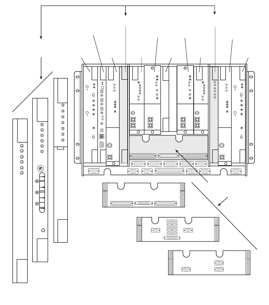
See Figure 1-2 through Figure 1-6. The following paragraphs describe required and
optional equipment for the MDR-8000 radio, in top-down breakdown order.
The MDR-8000 common shelf assembly (Table 1-6) consists of the shelf assembly
wired (SAW), shelf internal RF cables, front cover, and modules. Refer to Table 1-7
for supplied and optional equipment. The MDR-8000 SAW (PN 3EM 00116 ABAA
UDZZA), consists of backplane assembly, cardcage assembly, front cover, heatsinks,
brackets, mounting hardware, and decal.
Table 1-6 MDR-8000/i/s Common Shelf Assembly
UNIT/MODULE PART NUMBER APPLICATIONS
Single T/R, Domestic Kit 3DH 04122 AA Low Capacity DS1 Non-Standby
Applications.
Single T/R, International Kit 3DH 04122 AB Low Capacity E1 Non-Standby
Applications.
Dual T/R, Domestic Kit 3DH 04122 AC Low Capacity DS1 Hot-Standby
Applications
Dual T/R, International Kit 3DH 04122 AD Low Capacity E1 Hot-Standby Appli-
cations
Single T/R, Domestic Kit 3DH 04122 AG High Capacity DS3 Non-Standby
Applications.
Dual T/R, Domestic Kit 3DH 04122 AJ High Capacity DS3 Hot-Standby
Applications
Single T/R, Domestic Kit 3DH 04122 AL High Capacity OC3 Non-Standby
Applications With Wayside DS1
Dual T/R, Domestic Kit 3DH 04122 AN High Capacity OC3 Hot-Standby
Applications With Wayside DS1
MDR-8000 Series Radios 3DH03220
General Issue 6, July 2002
1-36
Figure 1-2 Typical MDR-8000/i/s/u Component Locations and Options
LBO/OC3 AUX INTFC
SELECT LBO/OC3 AUX INTFC
TO MATCH I/O INTFC
(DATA RATE)
CE–16BB
POWER
SUPPLY
A1
CE–16BB
POWER
SUPPLY
B1
UD–36A( )
RCVR
A2
AE–27AF
RELAY
INTFC
C2
AE–37Y
CNTR
C1
UD–35A( )
XMTR
A4
UD–35A( )
XMTR
B4
UD–51( )
PWR AMP
A5
UD–36A( )
RCVR
B2
UD–51( )
PWR AMP
B5
I/O INTFC
A3
I/O INTFC
B3
LMW-7030
07/08/02
ALM
ON
LINE
ALM
ON
LINE
SYNC
ALM
COM-
MON
LOSS
ALM
DX-35M
DS1/EI
SELECT A3 AND B3
I/O INTFC MODULES
BY DATA RATE
DX-35N
DS3
XMT
AUX
SC
ALM
RCVR
ON
RAD
LOF
WYSD
DS1
WYSD
ALM
DS3
ALIGN
RAD DADE
1
2
3
5
6
7
8
9
0
1
2
3
4
DX-35P
OC3
ALM
INSVC
OC3
IN
OC3
ALM
WYSD
ON
WYSD
ALM
OC3
OUT
DS1/E1 LBO
DS3 LBO
OC3 AUX INTFC
3DH03220 MDR-8000 Series Radios
Issue 6, July 2002 General
1-37
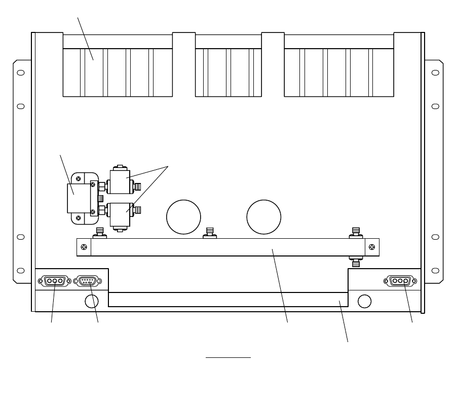
Figure 1-3 MDR-8000/i/s Component Locations, Rear View
HEAT SINK
REAR VIEW
(SINGLE ANTENNA CONFIGURATION)
MW211–0061–1B
101898
RCV
XMT
ANTENNA DIPLEXER A–SIDE
POWER
RF SWITCH
B–SIDE
POWER
SWITCH
RF
CIRCULATORS
DIPLEXER
MOUNTING
BRACKET

MDR-8000 Series Radios 3DH03220
General Issue 6, July 2002
1-38
Table 1-7 Supplied and Optional Equipment
UNIT/MODULE PART NUMBER REMARKS
AE-37Y-1 Controller: 3DH 03155 AA One Per Shelf
ELMC Option Key 695-5647-018 Required for remote provisioning and
downloading on DS1/E1 radios, and DS3
and OC3 radios without wayside DS1
ELMC Option Key 695-5647-019 Required for status of DS3 and OC3 radios
with wayside DS1 (no remote provisioning
or download capability provided)
ELMC Option Key 695-5647-020 Required for remote provisioning and
downloading of DS3 and OC3 radios with
wayside DS1
CE-16BB-1 Power Supply: 3DH 03164 AA Two included in Dual T/R assembly kit.
Fuse 264-0928-130 4 ea. 15A fast-blow fuses. (Two opera-
tional and two spares)
DX-35( ) I/O Interface: Capacity and Application
Dependent
Refer to Table 1-8
Two included in Dual T/R assembly kit.
UD-35( ) Transmitter: Application and Frequency
Dependent
Refer to Table 1-9
Two required for hot-standby
UM-62AX Crystal Oscillator Subboard 3DH 04123 AX
Frequency Dependent
The crystal oscillator subboard and crystal
part numbers define this unit. The crystal is
soldered to the oscillator subboard and fac-
tory tuned to the customers requirements.
See drawing 3DH 03177 0000 BJZZA in
the Diagrams Section.
Capacity Key Modulation and Capacity
Dependent Refer toTable 1-12.
UD-51( ) Power Amplifier Frequency and Output
Power Dependent.
Refer to Table 1-10.
Optional. Two required for hot-standby (if
equipped)
Cooling Fan Assembly Configuration Dependent Assembly with fans always required for PAs
with +27 or +29 (10/11 GHz), +28 dBm
(8 GHz) and +31 dBm (6 GHz) output
power. Assembly with fans and heat deflec-
tor are always required between radios in
a rack with multiple shelf stacking (regard-
less of PA output power).
Fan Assembly Without Lap Top Tray 967-0500-001
Fan Assembly With Lap Top Tray 967-0500-002

3DH03220 MDR-8000 Series Radios
Issue 6, July 2002 General
1-39
Fan Assembly With Fans 967-0500-003
Fan Alarm Board 3DH 04169 AA
Heat Deflector 3EM 03390 AA For use with fan assembly
UD-36( ) Receiver: Application and Frequency
Dependent
Refer to Table 1-11
Two required for hot-standby
UM-62AX Crystal Oscillator Sub
board 3DH 04123 AX
Frequency Dependent
The crystal oscillator subboard and crystal
part numbers define this unit. The crystal is
soldered to the oscillator subboard and fac-
tory tuned to the customers requirements.
See drawing 3DH 03177 0000 BJZZA in
the Diagrams section.
Capacity Key Modulation and Capacity
Dependent Refer toTable 1-12.
Line Buildout (LBO) Application and Distance
Dependent
Refer to Table 1-13.
AE-27AF Relay Interface 3DH 03219 AA Optional
2 X 4 Fiber Management Panel 3EM 0957 AA Optional. For use with OC3 2- or 4-fiber
switched configurations. Provides interface
for one or two radio shelves.
Single-mode Splitter/Combiner 1AB 12332 0023 Single-mode fiber interface. One per radio
shelf required.
Multi-mode Splitter/Combiner 1AB 12332 0022 Multi-mode fiber interface. One per radio
shelf required.
2 or 4 Fiber Management Panel 3EM 0957 AB Optional. For use with OC3 2- or 4-fiber
configurations. Provides interface for one
or two radio shelves. SC mating connectors
required.
Handset Kit 3CC07946AAAA Optional
Coiled Cord, RJ11 to RJ11 155-3362-010 Replaces RJ9 to RJ11 cord supplied with
handset kit.
Diplexer Filter Kit Frequency Dependent Refer to drawing 3DH 03177 0000
UDZZA in the Diagrams section.
Waveguide Iso-Adapters Frequency, Waveguide, and
Configuration Dependent Optional. Refer to drawing 3DH 03177
0000 BJZZA in the Diagrams section.
Waveguide Flanges Frequency, Waveguide, and
Configuration Dependent Optional. Refer to drawing 3DH 03177
0000 BJZZA in the Diagrams section.
Customer Interface Cables Applications Dependent Optional. Refer to drawing 3DH 03177
0000 BJZZA in the Diagrams section.
Table 1-7 (Cont.) Supplied and Optional Equipment
UNIT/MODULE PART NUMBER REMARKS

MDR-8000 Series Radios 3DH03220
General Issue 6, July 2002
1-40
XMTR Crystals should never be shipped as replacements
without being soldered and tuned up in an oscillator
assembly board at the factory.
Table 1-8 I/O Interface Options
TYPE NO. PART NUMBER CAPACITY/APPLICATIONS
DX-35M-1 3DH 03131 AA DS1/Domestic
DX-35M-2 3DH 03131 AB E1/International
DX-35N-1 3DH 03169 AG DS3 (1 or 3 DS3 Lines + DS1 Wayside per DS3)
DX-35P-1 3EM 03134 AA OC3 (3 STS1 Lines + DS1 Wayside per STS1)
CAUTION
Possibility of
Service
Interruption

3DH03220 MDR-8000 Series Radios
Issue 6, July 2002 General
1-41
Table 1-9 XMTR Options
TYPE NO. PART NUMBER APPLICATIONS/FREQUENCY
UD-35AN-1* 3DH 03137 AA DS1/E1 6400-6525 MHz
UD-35AN-2* 3DH 03137 AB DS1/E1 6425-6875 MHz
UD-35AN-3* 3DH 03137 AC DS1/E1 6875-7125 MHz
UD-35AN-4 3DH 03137 AD DS1/E1/DS3/OC3
6400-6525 MHz
UD-35AN-5 3DH 03137 AE DS1/E1/DS3/OC3
6525-6875 MHz
UD-35AN-6 3DH 03137 AF DS1/E1/DS3/OC3
6875-7125 MHz
UD-35AQ-1* 3DH 03236 AA DS1/E1 5850-5925 MHz
UD-35AQ-2* 3DH 03236 AB DS1/E1 5925-6425 MHz
UD-35AQ-3 3DH 03236 AC DS1/E1/DS3/OC3
5850-5925 MHz
UD-35AQ-4 3DH 03236 AD DS1/E1/DS3/OC3
5925-6425 MHz
UD-35AP-1* 3DH 03228 AA DS1/E1 10400-10700 MHz
UD-35AP-2* 3DH 03228 AB DS1/E1 10700-11200 MHz
UD-35AP-3* 3DH 03228 AC DS1/E1 11200-11700 MHz
UD-35AP-4 3DH 03228 AD DS1/E1/DS3/OC3
10400-10700 MHz
UD-35AP-5 3DH 03228 AE DS1/E1/DS3/OC3
10700-11200 MHz
UD-35AP-6 3DH 03228 AF DS1/E1/DS3/OC3
11200-11700 MHz
UD-35AR-1 3DH 04170 AA DS1/E1/DS3/OC3
7125-7750 MHz
UD-35AR-2 3DH 04170 AB DS1/E1/DS3/OC3
7700-8500 MHz
UD-35AS-1 3EM 09626 AA DS1/DS3
2025-2285 MHz
*Obsolete. Have been replaced with DS1/E1/DS3/OC3 XMTR.
MDR-8000 Series Radios 3DH03220
General Issue 6, July 2002
1-42
RCVR Crystals should never be shipped as replacements
without being soldered and tuned up in an oscillator
assembly board at the factory.
Table 1-10 PA Options
TYPE NO. PART NUMBER FREQUENCY/TOP OF STACK POWER
UD-51Z-1 3DH 03218 AA 5850-6425 MHz, +23 dBm
UD-51Z-2 3DH 03218 AB 6425-7125 MHz, +23 dBm
UD-51Z-3 3DH 03218 AC 5850-6425 MHz, +29 dBm
UD-51Z-4 3DH 03218 AD 6425-7125 MHz, +29 dBm
UD-51Z-5 3DH 03218 AE 5850-6425 MHz, +31 dBm
UD-51Z-6 3DH 03218 AF 6425-7125 MHz, +31 dBm
UD-51AA-1 3DH 04136 AA 10550-10700 MHz, +27 dBm
UD-51AA-2 3DH 04136 AB 10700-11200 MHz, +27 dBm
UD-51AA-3 3DH 04136 AC 11200-11700 MHz, +27 dBm
UD-51AA-4 3DH 04136 AD 10440-10700 MHz, +23 dBm
UD-51AA-5 3DH 04136 AE 10700-11200 MHz, +23 dBm
UD-51AA-6 3DH 04136 AF 11200-11700 MHz, +23 dBm
UD-51AA-7 3DH 04136 AG 10440-10700 MHz, +29 dBm
UD-51AA-8 3DH 04136 AH 10700-11200 MHz, +29 dBm
UD-51AA-9 3DH 04136 AJ 11200-11700 MHz, +29 dBm
UD-51AB-1 3EM 04070 AA 7125-7750 MHz, +28 dBm
UD-51AB-2 3EM 04070 AB 7700-8500 MHz, +28 dBm
UD-51AB-3 3EM 04070 AC 7125-7750 MHz, +30 dBm
UD-51AB-4 3EM 04070 AD 7700-8500 MHz, +30 dBm
UD-51AC-1 3EM 09037 AA 2025-2285 MHz, +32 dBm
CAUTION
Possibility of
Service
Interruption

3DH03220 MDR-8000 Series Radios
Issue 6, July 2002 General
1-43
Table 1-11 RCVR Options
TYPE NO. PART NUMBER APPLICATIONS/FREQUENCY
UD-36AN-1 3DH 03132 AA DS1/E1 6400-6525 MHz
UD-36AN-2 3DH 03132 AB DS1/E1 6525-6875 MHz
UD-36AN-3 3DH 03132 AC DS1/E1 6875-7125 MHz
UD-36AN-4* 3DH 03132 AD DS3 6400-6525 MHz
UD-36AN-5* 3DH 03132 AE DS3 6525-6875 MHz
UD-36AN-6* 3DH 03132 AF DS3 6875-7125 MHz
UD-36AN-7 3DH 03132 AG DS3/OC3 6400-6525 MHz
UD-36AN-8 3DH 03132 AH DS3/OC3 6525-6875 MHz
UD-36AN-9 3DH 03132 AJ DS3/OC3 6875-7125 MHz
UD-36AP-1 3DH 03231 AA DS1/E1 10400-10700 MHz
UD-36AP-2 3DH 03231 AB DS1/E1 10700-11200 MHz
UD-36AP-3 3DH 03231 AC DS1/E1 11200-11700 MHz
UD-36AP-4* 3DH 03231 AD DS3 10400-10700 MHz
UD-36AP-5* 3DH 03231 AE DS3 10700-11200 MHz
UD-36AP-6* 3DH 03231 AF DS3 11200-11700 MHz
UD-36AP-7 3DH 03231 AG DS3/OC3 10400-10700 MHz
UD-36AP-8 3DH 03231 AH DS3/OC3 10700-11200 MHz
UD-36AP-9 3DH 03231 AJ DS3/OC3 11200-11700 MHz
UD-36AQ-1 3DH 03239 AA DS1/E1 5850-5925 MHz
UD-36AQ-2 3DH 03239 AB DS1/E1 5925-6425 MHz
UD-36AQ-3* 3DH 03239 AC DS3 5850-5925 MHz
UD-36AQ-4* 3DH 03239 AD DS3 5925-6425 MHz
UD-36AQ-5 3DH 03239 AE DS3/OC3 5850-5925 MHz
UD-36AQ-6 3DH 03239 AF DS3/OC3 5925-6425 MHz
UD-36AR-1 3DH 04175 AA DS1/E1 7125-7750 MHz
UD-36AR-2 3DH 04175 AB DS1/E1 7700-8500 MHz
UD-36AR-3* 3DH 04175 AC DS3 7125-7750 MHz
UD-36AR-5 3DH 04175 AE DS3/OC3 7125-7750 MHz
UD-36AR-6 3DH 04175 AF DS3/OC3 7700-8500 MHz
UD-36AS-1 3EM 09628 AA DS1/DS3 2025-2285 MHz
*Obsolete. Have been replaced with DS3/OC3 RCVR.

MDR-8000 Series Radios 3DH03220
General Issue 6, July 2002
1-44
Table 1-12 Capacity Keys for Transmitter and Receiver Modules
CAPACITY KEY PN TCM/QAM RADIO TYPE CONFIGURATION
967-1609-001 32 TCM MDR-85XX-2 2 DS1
967-1609-002 32 TCM MDR-85XX-4 4 DS1
967-1609-003 32 TCM MDR-85XX-8 8 DS1
967-1609-004 32 TCM MDR-85XX-12 12 DS1
967-1609-005 32 TCM MDR-85XX-16 16 DS1
967-1609-006 128 TCM MDR-87XX-2 2 DS1
967-1609-007 128 TCM MDR-87XX-4 4 DS1
967-1609-008 128 TCM MDR-87XX-8 8 DS1
967-1609-009 128 TCM MDR-87XX-12 12 DS1
967-1609-010 128 TCM MDR-87XX-16 16 DS1
967-1609-011 32 TCM MDR-85XXi-2 2 E1
967-1609-012 32 TCM MDR-85XXi-4 4 E1
967-1609-013 32 TCM MDR-85XXi-8 8 E1
967-1609-014 32 TCM MDR-85XXi-12 12 E1
967-1609-015 32 TCM MDR-85XXi-16 16 E1
967-1609-016 128 TCM MDR-87XXi-2 2 E1
967-1609-017 128 TCM MDR-87XXi-4 4 E1
967-1609-018 128 TCM MDR-87XXi-8 8 E1
967-1609-019 128 TCM MDR-87XXi-12 12 E1
967-1609-020 128 TCM MDR-87XXi-16 16 E1
3EM 01583 AA 64 QAM MDR-86XX-45 1 DS3
3EM 01583 AB 64 QAM MDR-86XX-135 3 DS3
3EM 04176 AB 128 TCM MDR-87XX-155 3 STS1
*One capacity key is required for each UD-35( ) Transmitter and for each UD-36( ) Receiver.

3DH03220 MDR-8000 Series Radios
Issue 6, July 2002 General
1-45
1.11.1 Diplexer Filter Kits
Each kit contains diplexer, RF switch assembly, and cables for a specific con-
figuration. The RF switch assembly (PN 978-0490-001, 002, 003 consist of
isolators/circulators that are frequency dependent. For DS1 diplexer kit
options, refer to Integral LM drawing (3DH 04122 0000 UDZZA) in the Dia-
grams section. For DS3 and OC3 diplexer kit options, refer to Integral LM
drawing (3DH 04158 0000 UDZZA) in the Diagrams section.
1.11.2 Standard Filter Kits
Each standard filter kit contains filter, isolators, circulators, and cables for a
specific configuration. See Equipping Option Drawing (3DH 03177 0000
BJZZA) in the Diagrams section for information.
1.11.3 Cable Drop Kit Option
The cable drop kit option is available for all radio configurations. This
option replaces waveguide with coaxial cable. Refer to engineering drawing
967-1665-XXX in the Diagrams section for list of kit parts.
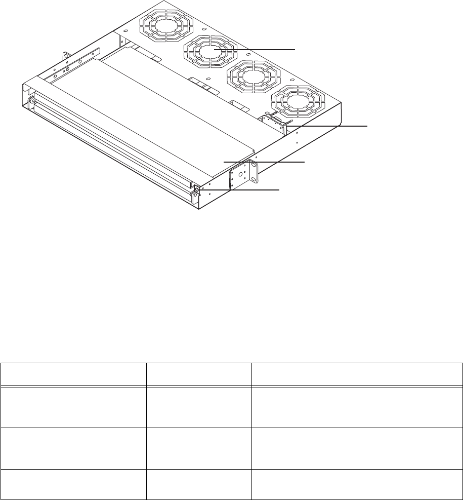
1.12 FAN ASSEMBLY
See Figure 1-4 and Figure 1-5. The Fan Assembly fits into a standard 19 in.
(483 mm) rack and occupies two vertical rack increments. Three options are avail-
able. Refer to Table 1-14 for details.
Table 1-13 LBO Options
MODULE/DESCRIPTION PART NUMBER APPLICATIONS
DS1 LBO (Domestic) 0-330 ft. (Near) 3DH 03144 AA Linear/Ring
DS1 LBO (Domestic) 330-650 ft.
(Far) 3DH 03144 AB Linear/Ring
E1 LBO (International) 3DH 03144 AC Linear/Ring
DS3 LBO Hot Standby/ Frequency
Diversity 3DH 04173 AK Linear/Ring
MDR-8000 Series Radios 3DH03220
General Issue 6, July 2002
1-46
Figure 1-4 Fan Assembly
When equipped with fans, the fan assembly mounts directly below the radio and
plugs into connector J302 on the MDR-8000 backplane. The four fans provide air flow
to help dissipate heat. Power is provided by the backplane. When not equipped with
fans, the assembly can be mounted in any rack location.
Table 1-14 Fan Assembly/Lap Top Tray Options
DESCRIPTION PART NUMBER REMARKS
Without Lap Top Tray 967-0500-001 Contains four fans that can be replaced individu-
ally. A front-panel alarm LED illuminates if a fan
fails.
With Lap Top Tray 967-0500-002 Contains a pullout tray to place a lap top computer
and four fans that can be replaced individually. A
front-panel alarm LED illuminates if a fan fails.
With Lap Top Tray, Without Fans 967-0500-003 Contains a pullout tray to place a lap top computer
and no fans or front-panel alarm LED.
FAN ALARM CARD
LMW-7031
07/08/02
LAPTOP TRAY
FAN (4 EA)
ALM LED
FRONT
OF FAN ASSEMBLY
3DH03220 MDR-8000 Series Radios
Issue 6, July 2002 General
1-47
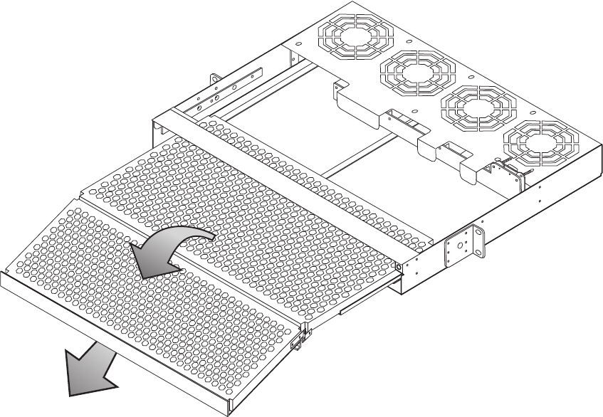
Figure 1-5 Fan Assembly With Laptop Tray Fully Extended
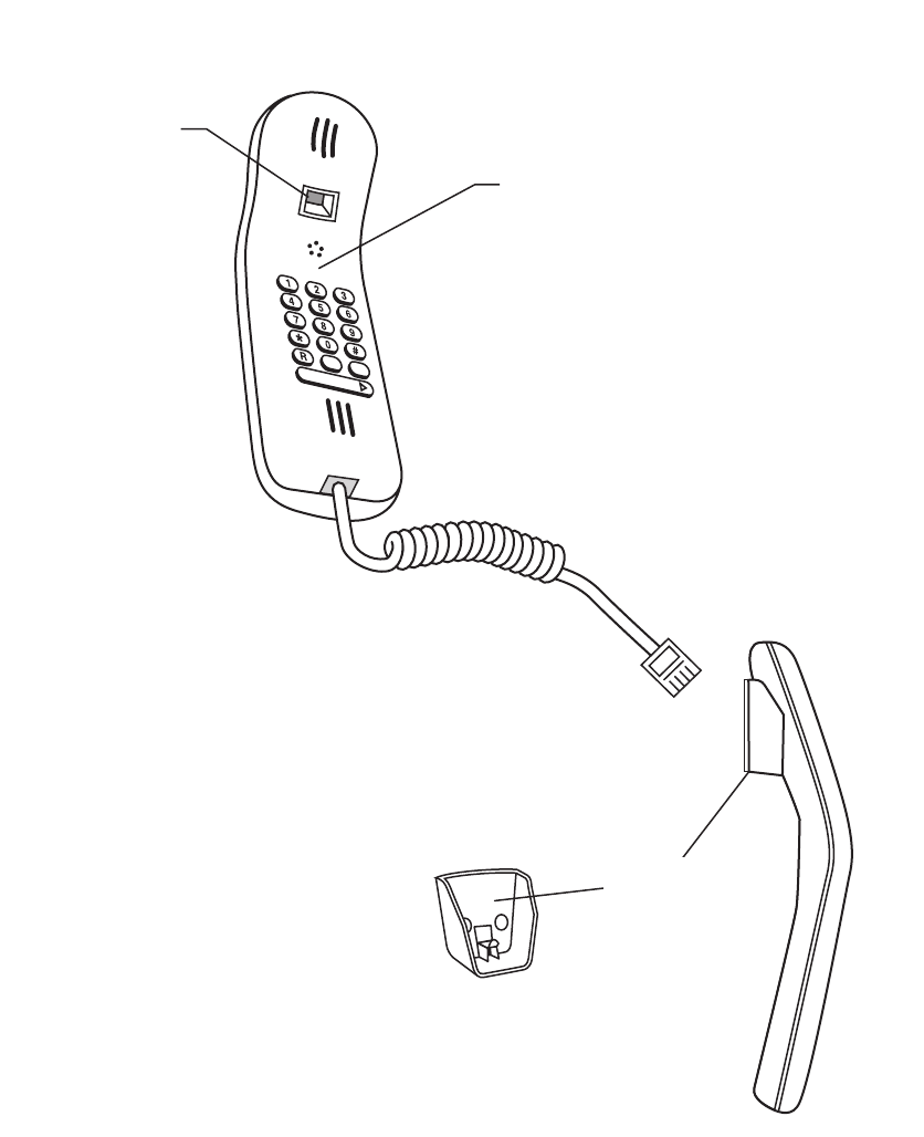
1.13 HANDSET KIT
See Figure 1-6. The handset kit consists of a handset, telephone cord, and handset
holder. The handset is a push button multi-frequency type handset. The handset cord
supplied with the handset contains an RJ11 connector on one end and RJ9 connector
on the other end. A recommended cable is available with RJ11 connectors on both
ends (PN 155-3362-010). The handset holder attaches to any flat surface with double-
sided tape.
LAPTOP TRAY
EXTENDED
LMW-7032
07/08/02
MDR-8000 Series Radios 3DH03220
General Issue 6, July 2002
1-48
Figure 1-6 Handset Kit
TONE/PULSE (FV/DC)
MODE SWITCH SET
TO FV FOR TONES
HANDSET
LMW-7034
07/09/02
HANDSET
HOLDER