Alcatel USA 8705U-155 Digital Modulated Radio User Manual 00 Book I 6 fullTOC
Alcatel USA Marketing, Inc. Digital Modulated Radio 00 Book I 6 fullTOC
Contents
- 1. Users Manual part one
- 2. Users Manual part two
Users Manual part one

MDR-8000
/i/s
/u
Alcatel Part Number 3EM15726AA
3400 West Plano Parkway
Plano, Texas 75075-5813 U.S.A.
Part 1 of 2
Issue 2, June, 2004
Microwave Digital Radios
Users Manual

Table of Contents
TOC-i
Page
Section 1 General
1.1
INTRODUCTION
.............................................................................................1-1
1.2
CONTENT
.......................................................................................................1-1
Section 2 Operation
2.1
GENERAL
........................................................................................................2-1
2.2
TURN-ON
........................................................................................................2-1
2.3
USER SYSTEM INTERFACE (USI) PROVISIONING FUNCTION/OPERATION
......2-2
2.4
OPERATING PROCEDURES
..............................................................................2-2
2.4.1
Radio Receiver Manual Switching
.....................................................................2-2
2.4.2
Radio Transmitter Manual Switching
.................................................................2-5
2.4.3
Radio I/O Interface Manual Switching
..............................................................2-5
2.4.4
MCS-11 Operation
..........................................................................................2-7
2.4.5
Lamp Tests
.......................................................................................................2-8
2.4.6
Alarm Checks
..................................................................................................2-8
2.4.7
Orderwire Operation
.......................................................................................2-8
2.4.8
Initiating Outgoing Orderwire Calls
..................................................................2-8
2.4.9
Answering Incoming Orderwire Calls
................................................................2-8
2.5
TURN-OFF PROCEDURE
...................................................................................2-9
2.6
EMERGENCY OPERATION
..............................................................................2-9
2.7
MODEM OPERATION
......................................................................................2-9
2.8
CONTROLS, INDICATORS, TEST POINTS, AND CONNECTORS
.......................2-9
Section 3 Interconnect
3.1
SECTION INTRODUCTION
..............................................................................3-1
3.2
INSTALL POWER CABLE ASSEMBLIES
...............................................................3-1

Page
TOC-ii
3.3
PDU STRAPPING AND CONNECTIONS
........................................................... 3-3
3.4
SHELF/RACK ALARM CONNECTION
.............................................................. 3-5
3.5
DS1 CONNECTIONS (J303 IN AND J304 OUT)
.............................................. 3-8
3.6
DS1 REPEATER (J314 ON ONE SHELF TO J314 ON SECOND SHELF)
............ 3-10
3.7
DS3 LBO STRAPPING AND CONNECTIONS
................................................. 3-11
3.8
DS3 LBO DS3 BNC CONNECTIONS (J21 THROUGH J26)
............................. 3-12
3.9
DS3 LBO WAYSIDE DS1 CONNECTIONS (J201 IN AND J202 OUT)
............. 3-13
3.9.1
Wayside DS1 Terminal
.................................................................................. 3-14
3.9.2
Wayside DS1 Repeater
.................................................................................. 3-15
3.10
DS3 REPEATER (J401 ON ONE SHELF TO J401 ON SECOND SHELF)
............ 3-15
3.11
FIBER OPTIC CABLE CONNECTIONS
............................................................. 3-16
3.11.1
2 or 4 Fiber Management Panel
..................................................................... 3-17
3.11.2
2x4 Fiber Switched Management Panel
.......................................................... 3-17
3.12
OC3 AUX INTERFACE BOARD WAYSIDE DS1 CONNECTIONS
(J201 IN AND J202 OUT)
.............................................................................. 3-20
3.12.1
Wayside DS1 Terminal
.................................................................................. 3-20
3.12.2
Wayside DS1 Repeater
.................................................................................. 3-20
3.13
OC3 REPEATER (J203 ON ONE SHELF TO J203 ON SECOND SHELF)
........... 3-21
3.14
USI/CONTROLLER CABLE CONNECTION TO LAPTOP (J301)
......................... 3-22
3.15
SERVICE CHANNEL
....................................................................................... 3-22
3.15.1
Handset Jack
................................................................................................. 3-23
3.15.2
Service Channels Provisioning Options
............................................................ 3-24
3.15.3
Audio 1, Audio 2 (J316, J317)
....................................................................... 3-24
3.15.4
RS-232-1, RS-232-2 (J312, J313)
.................................................................... 3-27
3.15.5
MCS-11 Connections
..................................................................................... 3-28
3.15.6
ELMC (J315, J318)
........................................................................................ 3-37
3.16
FOREIGN ALARM INTERFACE (J305)
............................................................. 3-41
3.17
ALARM, STATUS, CONTROLS INTERCONNECT
............................................. 3-44
3.17.1
Controller Bus
................................................................................................ 3-46
3.17.2
Control Inputs
................................................................................................ 3-46
3.17.3
Station Alarm Inputs/TBOS Interface
............................................................... 3-46

Page
TOC-iii
3.17.4
Station Alarm Wiring
.....................................................................................3-47
3.17.5
Relay Alarm/Status Outputs
............................................................................3-48
3.17.6
Relay Control Outputs
....................................................................................3-51
Section 4 Initial Turnup
4.1
SECTION INTRODUCTION
..............................................................................4-1
4.2
RECOMMENDED SEQUENCE
.........................................................................4-1
4.3
PROVISIONING RADIO
...................................................................................4-3
Section 5 Maintenance
5.1
GENERAL
........................................................................................................5-1
5.2
MAINTENANCE PHILOSOPHY
.........................................................................5-2
5.3
SPECIAL TOOLS
...............................................................................................5-4
5.4
PERSONAL COMPUTER (PC)
............................................................................5-4
5.5
ALARM MONITORING AND INSPECTION
.......................................................5-4
5.6
RECOMMENDED PERIODIC CHECKS
...............................................................5-6
5.7
TROUBLESHOOTING
.......................................................................................5-6
5.7.1
Test Procedures
................................................................................................5-6
5.7.2
Linear/Ring Radio Troubleshooting
...................................................................5-6
5.7.3
Ring Radio Troubleshooting
............................................................................5-18
5.8
MODULE REPLACEMENT
...............................................................................5-19
5.9
CHANGING FREQUENCY
.............................................................................5-22
5.10
CLEANING
....................................................................................................5-22
Appendix A CommPak Indoor Shelf
A.1
COMPONENT LOCATIONS AND OPTIONS
....................................................A-1
A.1.1
External Fan Assembly
......................................................................................A-5
A.2
INTERCONNECT
.............................................................................................A-5
A.2.1
Power Cable Assembly
.....................................................................................A-5
A.2.2
External Fan Assembly
......................................................................................A-8
A.2.3
SHELF/RACK ALARM CONNECTION
..............................................................A-9

Page
TOC-iv
A.2.4
DS1 LBO Connections
....................................................................................A-11
A.2.5
DS3 LBO CONNECTIONS
.............................................................................A-13
A.2.6
Fiber Optic Cable Connections
.......................................................................A-15
A.2.7
OC3 AUX Interface Board Connections
...........................................................A-16
A.2.8
Controller Cable Connection (J301)
................................................................A-18
A.2.9
Audio Cable Connections
...............................................................................A-18
A.2.10
RS-232 Cable Connections
.............................................................................A-19
A.2.11
MCS-11 Cable Connections
...........................................................................A-20
A.2.12
ELMC Cable Connections
...............................................................................A-24
A.2.13
Foreign Alarm Interface (J305)
........................................................................A-25
A.2.14
Station Alarm Wiring
.....................................................................................A-27
A.3
MAINTENANCE
............................................................................................A-28
A.3.1
Warnings and Cautions
.................................................................................A-28
A.3.2
Troubleshooting
.............................................................................................A-28
A.3.3
Module Replacement
......................................................................................A-28
A.4
CAPACITY UPGRADE DS1 TO DS3 OR DS3 TO OC3
.....................................A-37
A.5
CHANGING SYSTEM SOFTWARE
.................................................................A-37

1-1
1
GENERAL
1.1
INTRODUCTION
This MDR-8000 Users Manual contains information on the MDR-8000 Hot-Standby Shelf,
MDR-8000 CommPak Indoor Shelf, and MDR-8000 CommPak Outdoor Unit as follows:
MDR-8000 Hot-Standby Shelf – Section 1 through Section 5
MDR-8000 CommPak Indoor Shelf – Appendix A
MDR-8000 CommPak Outdoor Unit – Appendix B (to be supplied)
The information in the Users Manual is a summary of the overall instruction book that is
located on the attached CD. The summary information is provided to support initial turnup,
day-to-day operation, and maintenance of the MDR-8000 equipment.
1.2
CONTENT
Refer to Table 1-1. The
MDR-8000 Instruction Book
Section/Appendix column lists the
parts of the
MDR-8000 Instruction Book
, PN 3DH03220. A check mark under the Users
Manual column or the Instruction Book CD column indicates that this information is
located in either the Users Manual, the Instruction Book, or both.
Table 1-1 Information Location
Location
Section/Appendix
Users Manual
MDR-8000 Instruction Book
Glossary
√
General
√
Application
√
Functional Description
√
Physical Installation
√
Interconnect
√
√
Initial Turnup
√
√
Operation
√
√
Users Guide
√
Maintenance
√
√
Diagrams
√
Rack Installation
√
Alarm/Status/Control
√
MCS-11 Reference Guide
√
Modem Provisioning
√
Maintenance Support Procedures
√
CommPak Indoor Shelf
√
√
1-2
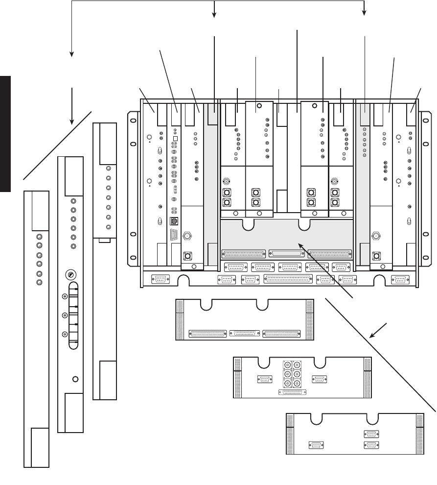
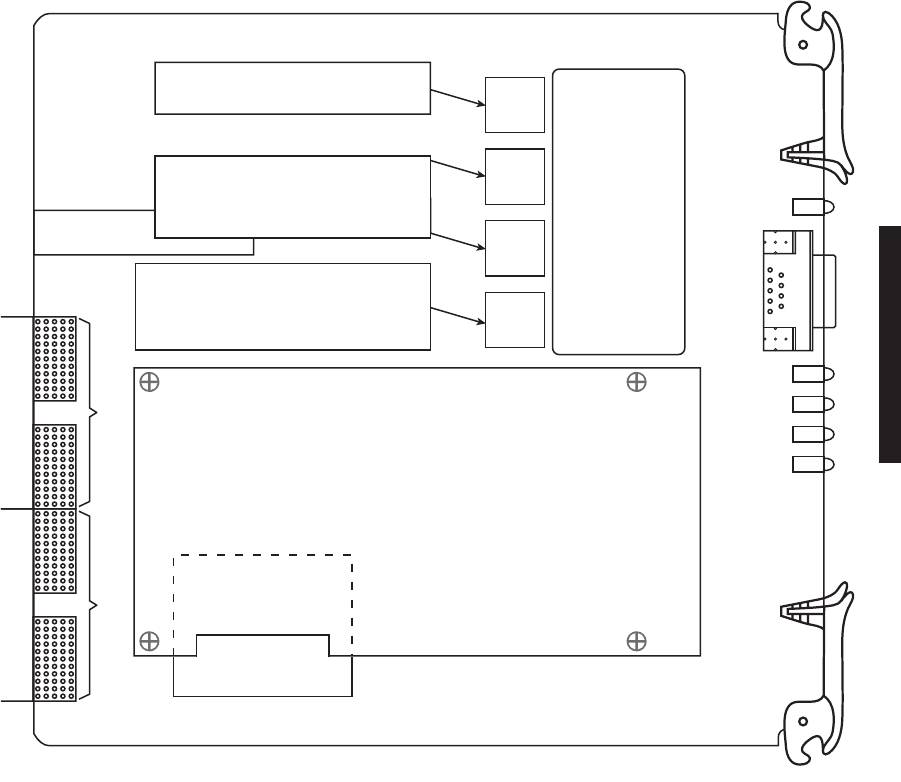
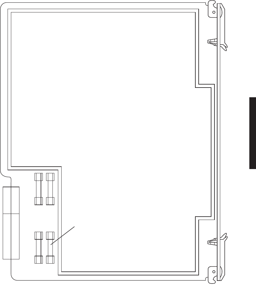
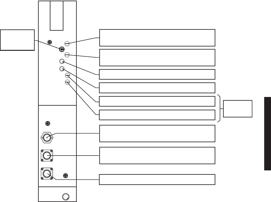
Figure 1-1 Typical MDR-8000 Hot-Standby Shelf Component Locations and Options (Sheet 1 of 3)
LBO/OC3 AUX INTFC
SELECT LBO/OC3 AUX INTFC
TO MATCH I/O INTFC
(DATA RATE)
CE–16BB
POWER
SUPPLY
A1
CE–16BB
POWER
SUPPLY
B1
UD–36A( )
RCVR
A2
AE–37Y
CONTROLLER
C1
AE-27AA
TMN INTFC
OR BLANK C3
UD–35A( )
XMTR
A4
UD–35A( )
XMTR
B4
UD–51( )
PWR AMP
A5
UD–36A( )
RCVR
B2
UD–51( )
PWR AMP
B5
I/O INTFC
A3
I/O INTFC
B3
LMW-7030-SM
06/09/04
ALM
ON
LINE
ALM
ON
LINE
SYNC
ALM
COM-
MON
LOSS
ALM
DX-35M
DS1/EI
SELECT A3 AND B3
I/O INTFC MODULES
BY DATA RATE
DX-35N
DS3
XMT
AUX
SC
ALM
RCVR
ON
RAD
LOF
WYSD
DS1
WYSD
ALM
DS3
ALIGN
RAD DADE
1
2
3
5
6
7
8
9
0
1
2
3
4
DX-35P
OC3
ALM
INSVC
OC3
IN
OC3
ALM
WYSD
ON
WYSD
ALM
OC3
OUT
DS1/E1 LBO
DS3 LBO
OC3 AUX INTFC
AE–27AF
RELAY
INTFC
C2
1-3
)
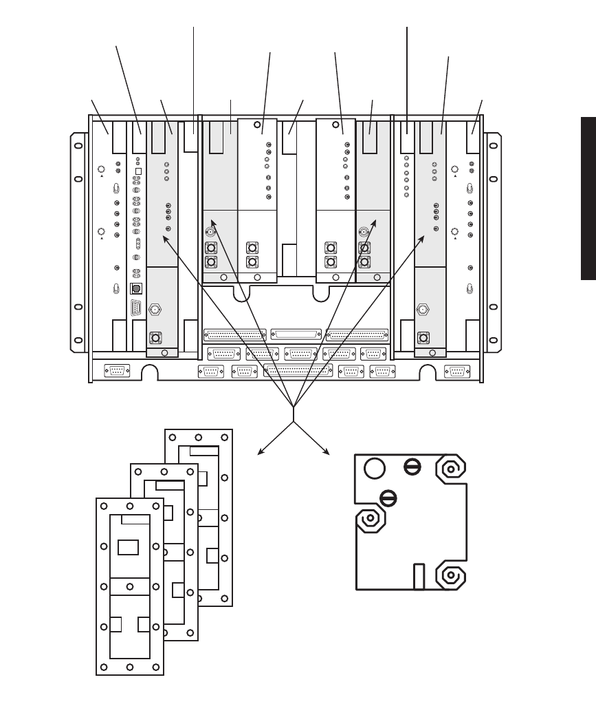
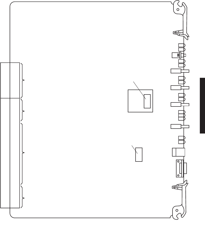
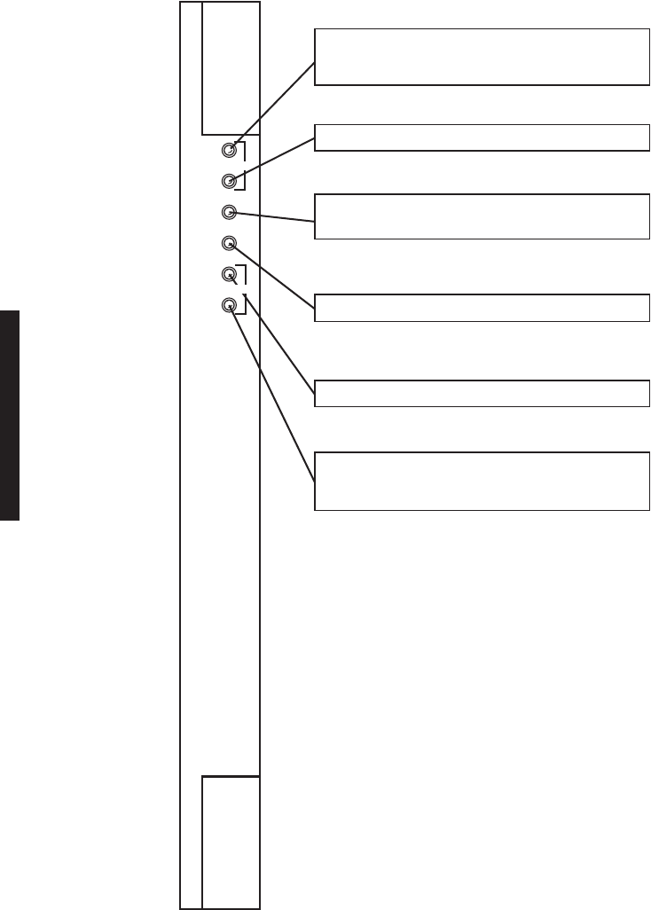
Figure 1-1 Typical MDR-8000 Hot-Standby Shelf Component Locations and Options (Sheet 2 of 3)
LBO/OC3 AUX INTFC
SELECT CAPACITY
KEY BY DATA RATE.
SELECT XTAL
OSCILLATOR
SUBBOARD BY
CRYSTAL
FREQUENCY.
SELECT DS1/E1 CAPACITY KEY BY
CAPACITY AND MODULATION SCHEME
2, 4, 8, 12, 16 DS1/E1 AND 32 OR 128 TCM.
SELECT DS3 CAPACITY KEY BY
NUMBER OF LINES – 1, 2, OR 3 LINES.
SELECT OC3 CAPACITY KEY BY
NUMBER OF STS1 LINES – 1 OR 3 LINES.
CE–16BB
POWER
SUPPLY
A1
CE–16BB
POWER
SUPPLY
B1
UD–36A( )
RCVR
A2
AE–27AF
RELAY
INTFC
C2
AE–37Y
CONTROLLER
C1
UD–35A( )
XMTR
A4
UD–35A( )
XMTR
B4
UD–51( )
PWR AMP
A5
UD–36A( )
RCVR
B2
UD–51( )
PWR AMP
B5
I/O INTFC
A3
I/O INTFC
B3
LMW-9051-SM
02/15/04
DS1/E1
DS3
OC3
1-4
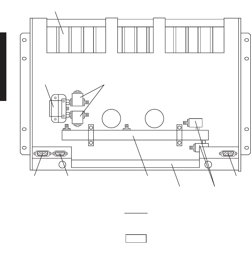
Figure 1-1 Typical MDR-8000 Hot-Standby Shelf Component Locations, and Options (Sheet 3 of 3 )
RF
SWITCH
B-SIDE
POWER
RF SWITCH
XMT
A
RCV
ANT
B
RCV
ISOLATORS
HEAT
SINK
A-SIDE
POWER
LMW-7211-SM
06/08/04
DIPLEXER
FILTER
MOUNTING
BRACKET
ISOLATOR
DIPLEXER
FILTER
REAR VIEW
(TYPICAL HOT-STANDBY 1:10 COUPLER
SINGLE ANTENNA CONFIGURATION)
Location of A and B RCV ports on diplexer filter varies,
depending on RF frequency. For some frequencies, A and
B ports reverse location.
Note

2-1
2
OPERATION
2.1
GENERAL
This section contains turn-on, normal operation, turn-off, and emergency operating
procedures plus a description of controls. indicators, test points, and connectors for the
MDR-8000 Series Microwave Digital Radios.
Before performing any procedures, operating personnel should become
familiar with the locations of power distribution units and circuit
breakers. If an equipment performance problem occurs during the fol-
lowing procedures, refer to the Maintenance section.
2.2
TURN-ON
The radio is designed to operate continuously without operator intervention. After initial
installation and power turn-on, operating procedures are limited to periodic visual lamp
checks, alarm checks, and answering or initiating orderwire service calls. Turn-on procedures
are needed only if the system has been turned off due to a malfunction or during maintenance.
Exposure to energy radiated at microwave frequencies can
cause eye damage and eventual blindness. Do not operate
the system with either the transmit or the receive waveguide
port unterminated. Do not look into the waveguide run or the
antenna of an operating radio.
Until all radios in the transmission link are interconnected, turned on,
and operating properly, alarm conditions may exist.
Perform the following procedure to turn on the MDR-8000 series radios:
1
On all power supply modules, set power ON/OFF switches to ON.
2
Verify that power distribution unit rack alarm indicator (if any) is not lighted.
If indicator is lighted, troubleshoot as described in the Maintenance section.
3
Verify that no red indicators are lighted. If a red indicator is lit, troubleshoot
as described in the Maintenance section.
4
Perform lamp test by momentarily holding OVRD-ACO/LT switch on control-
ler to ACO/LT.
All indicator lamps/LEDs should light.
Note
WARNING
Possibility of
Damage
to Equipment
Note

2-2
2.3
USER SYSTEM INTERFACE (USI) PROVISIONING FUNCTION/OPERATION
The User System Interface (USI) software is used for maintenance and support of the
radio including fault and status reporting. Refer to the Initial Turn-Up section for instruc-
tions on loading and running the software. Refer to the User’s Guide section for descrip-
tions and functions of the menus.
Refer to the Software Release Notes before performing any operating,
provisioning, or maintenance function on this equipment. The Software
Release Notes may contain information affecting these functions that is
not contained in this instruction manual.
2.4
OPERATING PROCEDURES
The USI computer is the main control for the radio. If instructions for
setting up the USI computer are needed, refer to Initial Turn-Up section.
After installation and turn-on, operating procedures are limited to periodic alarm checks
and, when necessary, answering or initiating orderwire calls. Automatic and manual
switching are provided for equipment protection. Manual switching may be accomplished
using the Control screen on the USI computer or the switches on the front panel of the con-
troller module. The following paragraphs provide operating procedures for manual
switchover of protected radio systems.
2.4.1
Radio Receiver Manual Switching
When used in conjunction with a RCVR manual switch, press the
OVRD switch to lock the receiver on line regardless of alarms. Press
again to unlock.
Controller Switch
Perform RCVR manual switch (Figure 2-1) using controls on front panel of controller
module:
USI Switch
Perform RCVR manual switch (Figure 2-2) using the USI control screen.
Note
Note
Note
2-3
Figure 2-1 Manual Switch From Controller Front Panel
ALM
OFF
NORM
SHLF
ALM
ALM
ON
LINE
RX
L
AB
ALM
ON
LINE
TX
L
AB
ALM
RSP
RSP
ON
LINE
I/O
L
A
POLL
LCL
RMT
B
A
C
O
/
L
T
O
V
R
D
RF RPTR
CMD
IDLE
T
E
L
U
S
I
TOGGLE SWITCH LEFT TO SWITCH A XMTR,
RCVR, OR I/O MODULE IN-SERVICE AND
TOGGLE SWITCH RIGHT TO SWITCH B
XMTR, RCVR, OR I/O MODULE IN-SERVICE.
LMW-5078-sm
08/15/02
OVERRIDE (OVRD) LOCKS XMTR, RCVR, OR
I/O MODULE, SELECTED ABOVE IN-SERVICE,
REGARDLESS OF ALARMS.
TO ENABLE OVERRIDE:
1. PRESS AND HOLD TX A/B ON LINE,
RX A/B ON LINE, OR I/O A/B ON LINE
SWITCH.
2. TOGGLE ACO/LT OVRD SWITCH TO OVRD
POSITION.
3. RELEASE A/B ON LINE SWITCH.
TO DISABLE OVERRIDE:
TOGGLE ACO/LT OVRD SWITCH TO OVRD
POSITION.
NOTE
2-4
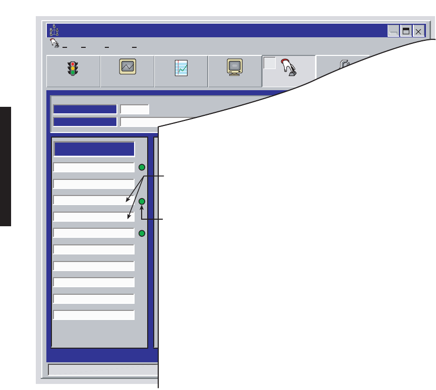
Figure 2-2 RCVR Manual Switch Using USI Control Screen
File
Controls -- MDR-8000 DS3
View Setup Options
Alarm Status Performance Station Alarm User Control ProvisioningAnalog Monitor
F4 F5 F6 F7 F8 F9
LOCAL CONTROLS
Communicating*
ELMC Address:
Description:
SILVERTON
A Transmitter On Line
B Transmitter On Line
A Receiver On Line
B Receiver On Line
A I/O On Line
B I/O On Line
A ATPC HIGH Power Lock
B ATPC HIGH Power Lock
A ATPC LOW Power Lock
B ATPC LOW Power Lock
J7915
IN-SERVICE
A I/O LOOPBACK
Line 1 loopback
Line 2 loopback
Line 3 loopback
B I/O LOOPBACK
Control #1
Control #2
Control #3
Control #4
Control #5
Control #6
SYSTEM LOOP-BACK
DS1 LINE LOOP-BACK RCV to XMT
USER CONTROLS
Thursday, November 30, 2000 1:44:19 PM USI Version R1.02 Controller Version R1.02
LMW-5081-sm
08/15/02
2. SELECT RCVR TO PUT IN-SERVICE.
1. OPEN USI CONTROLS SCREEN.
3. SELECT YES ON CONFIRMATION MESSAGE
TO ENABLE FUNCTION.
4. VERIFY GREEN IN-SERVICE STATUS CIRCLE DISPLAYS.

2-5
2.4.2
Radio Transmitter Manual Switching
Switching the radio transmitter may momentarily interrupt
traffic. Before switching the transmitter, obtain permission
from the proper authority.
When used in conjunction with a XMTR manual switch, press the
OVRD switch to lock the XMTR on line regardless of alarms. Press
again to unlock.
Controller Switch
Perform XMTR manual switch (Figure 2-1) using controls on front panel of controller module.
USI Switch
Perform XMTR manual switch (Figure 2-3) using the USI control screen.
2.4.3
Radio I/O Interface Manual Switching
Traffic and auxiliary channel service will be momentarily
interrupted. Obtain proper authorization before making this
switch.
When used in conjunction with an I/O interface manual switch, press
the OVRD switch to lock the I/O interface on line regardless of alarms.
Press again to unlock.
CAUTION
Possibility of
Service
Interruption
Note
CAUTION
Possibility of
Service
Interruption
Note
2-6
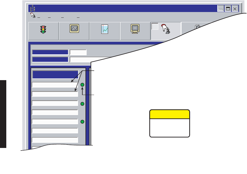
Figure 2-3 XMTR Manual Switch Using USI Control Screen
Controller Switch
Perform I/O manual switch (Figure 2-1) using controls on front panel of controller module.
USI Switch
Perform I/O manual switch (Figure 2-4) using the USI control screen.
File
Controls -- MDR-8000 DS3
View Setup Options
Alarm Status Performance Station Alarm User Control ProvisioningAnalog Monitor
F4 F5 F6 F7 F8 F9
LOCAL CONTROLS
Communicating*
ELMC Address:
Description:
SILVERTON
A Transmitter On Line
B Transmitter On Line
A Receiver On Line
B Receiver On Line
A I/O On Line
B I/O On Line
A ATPC HIGH Power Lock
B ATPC HIGH Power Lock
A ATPC LOW Power Lock
B ATPC LOW Power Lock
J7915
IN-SERVICE
A I/O LOOPBACK
Line 1 loopback
Line 2 loopback
Line 3 loopback
B I/O LOOPBACK
Control #1
Control #2
Control #3
Control #4
Control #5
Control #6
SYSTEM LOOP-BACK
DS1 LINE LOOP-BACK RCV to XMT
USER CONTROLS
Thursday, November 30, 2000 1:44:19 PM USI Version R1.02 Controller Version R1.02
LMW-5076-SM
06/12/04
1. SELECT XMTR TO PUT IN-SERVICE.
2. SELECT YES ON CONFIRMATION MESSAGE
TO ENABLE FUNCTION.
3. VERIFY GREEN IN-SERVICE STATUS CIRCLE DISPLAYS.
Switching the radio transmitter may momentarily interrupt
traffic. Switching I/Os will momentarily interrupt traffic and
auxiliary channel service. Before switching, obtain permission
from the proper authority.
CAUTION
Possibility of
Service
Interruption
2-7
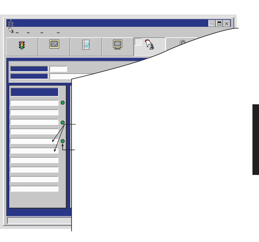
Figure 2-4 I/O Manual Switch Using USI Control Screen
2.4.4
MCS-11 Operation
An Operational Support System (OSS) provides a means to remotely monitor and control
an MDR-8000 radio via an MCS-11 Monitor and Control System polling master. A Remote
Station Summary (RSS), a Remote Detail Scanner (RDS), a Remote Analog Scanner (RAS),
and a Remote Control Decoder (RCD) are available at the polling master for each radio
network element. The remote station OSS addresses are programmed during radio provi-
sioning using the USI laptop computer. (Refer to radio provisioning in the Initial Turn-Up
section.) Refer to Appendix A at the end of this instruction book for MCS-11 details, includ-
ing alarm/status mapping and connector information.
File
Controls -- MDR-8000 DS3
View Setup Options
Alarm Status Performance Station Alarm User Control ProvisioningAnalog Monitor
F4 F5 F6 F7 F8 F9
LOCAL CONTROLS
Communicating*
ELMC Address:
Description:
SILVERTON
A Transmitter On Line
B Transmitter On Line
A Receiver On Line
B Receiver On Line
A I/O On Line
B I/O On Line
A ATPC HIGH Power Lock
B ATPC HIGH Power Lock
A ATPC LOW Power Lock
B ATPC LOW Power Lock
J7915
IN-SERVICE
A I/O LOOPBACK
Line 1 loopback
Line 2 loopback
Line 3 loopback
B I/O LOOPBACK
Control #1
Control #2
Control #3
Control #4
Control #5
Control #6
SYSTEM LOOP-BACK
DS1 LINE LOOP-BACK RCV to XMT
USER CONTROLS
Thursday, November 30, 2000 1:44:19 PM USI Version R1.02 Controller Version R1.02
LMW-5077-sm
08/15/02
2. SELECT I/O INTERFACE MODULE TO PUT IN-SERVICE.
1. OPEN USI CONTROLS SCREEN.
3. SELECT YES ON CONFIRMATION MESSAGE
TO ENABLE FUNCTION.
4. VERIFY GREEN IN-SERVICE STATUS CIRCLE DISPLAYS.

2-8
2.4.5
Lamp Tests
Perform lamp tests by pressing and holding
ACO/LT OVRD
switch on controller front panel
in
ACO/LT
position. All indicators on controller and indicators on all equipped modules
should light. Release
ACO/LT OVRD
switch.
2.4.6
Alarm Checks
The USI Alarm and Status screens provide alarms and status for the radio. Refer to
description of alarms and status in the maintenance section.
2.4.7
Orderwire Operation
These operating procedures describe use of the orderwire system to answer incoming calls
and initiate outgoing calls. The DTMF function allows the user to ring the dialed station.
2.4.8
Initiating Outgoing Orderwire Calls
1
Connect telephone to J302 TEL jack on front panel of AE-37( ) Controller.
2
Dial the 3-digit DTMF extension on the telephone keypad to call specific party
or press the * key on keypad to initiate CALL signaling to all
stations.
2.4.9
Answering Incoming Orderwire Calls
Call can be heard by all stations.
1
When the buzzer sounds, alerting the operator there is an incoming call,
connect telephone to J302 TEL jack on front panel of AE-37( ) Controller and
turn ON-HOOK/OFF-HOOK switch to OFF-Hook position.
2
To terminate call, turn ON-HOOK/OFF-HOOK switch to ON-Hook
position.
During the DTMF dialing process, if an incorrect number sequence has
been dialed, press # to reset DTMF digit accumulator to zero. A redial
can then be initiated.
If 1.5 seconds elapse between dialed digits, the DTMF digit accumula-
tor resets to zero, and a redial must be initiated.
Note
Note
Note

2-9
Caller can press # to clear all flashing CALL indicators at all DTMF
sites equipped with the DTMF signaling option (a tone is transmitted).
2.5
TURN-OFF PROCEDURE
The radio is designed for continuous operation. If power must be removed while perform-
ing maintenance on a particular cabinet or shelf, power can be removed by turning off
associated power supplies.
Normally, the turn-off procedures are not used. System design allows
maintenance of the rack without interrupting service. It is recom-
mended that turn-off be performed only in an emergency.
2.6
EMERGENCY OPERATION
If an emergency occurs, such as a short circuit or a fire, turn off all MDR-8000 Microwave
Digital Radio power supplies as quickly as possible.
2.7
MODEM OPERATION
Refer to the Modem Provisioning section for modem connection and setup procedures.
2.8
CONTROLS, INDICATORS, TEST POINTS, AND CONNECTORS
Do not adjust controls unless instructed to do so in an installa-
tion or maintenance procedure. Unauthorized adjustment of
controls illustrated and described in this section may interrupt
traffic and/or degrade system performance.
Controls, indicators, test points, and connectors used in normal operation or referenced in
procedures are shown in Figure 2-5 through Figure 2-16. The figures are arranged in
alphabetical order according to the type number.
Note
Note
CAUTION
Possibility of
Service
Interruption
2-10
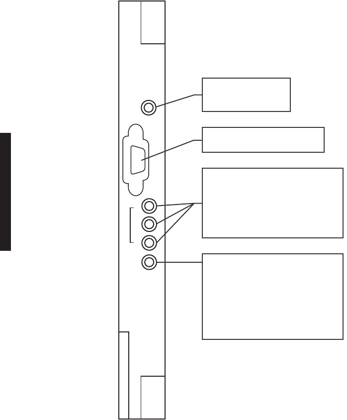
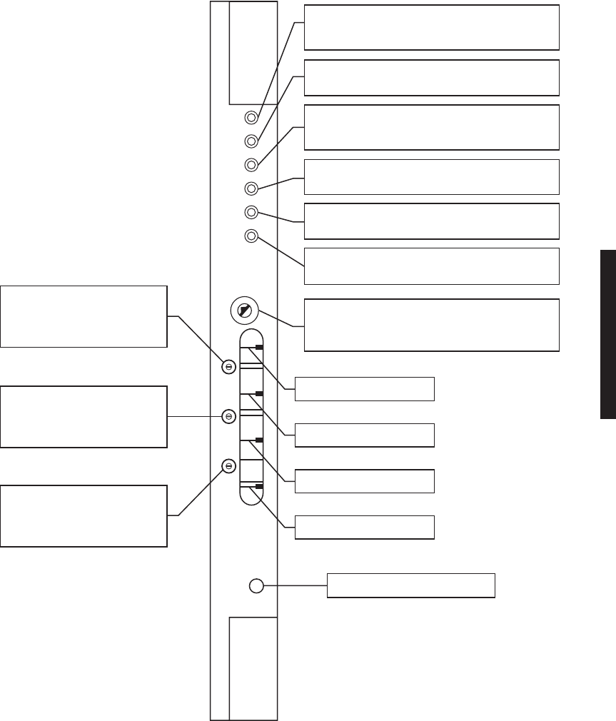
Figure 2-5 AE-37AA TMN Interface Module Controls, Indicators, and Connectors (Sheet 1 of 2)
ALM
1
2
3
PPP
C
R
A
F
T
E
T
H
E
R
N
E
T
RED LED INDICATES
MODULE FAULT OR
REBOOT IN PROGRESS.
9-PIN D-TYPE CONNECTOR FOR
INTERFACE WITH COMPUTER.
DUAL-COLOR LED (GREEN/YELLOW)
LIGHTS GREEN TO INDICATE LINK IS
ACTIVE. BLINKS GREEN WHEN RE-
CEIVING DATA PACKETS ON PORT.
LIGHTS YELLOW TO INDICATE PORT
IS MISCONFIGURED. BLINKS YELLOW
TO INDICATE COLLISIONS.
DUAL-COLOR LED (GREEN/YELLOW)
LIGHTS GREEN TO INDICATE LINK IS
ACTIVE. BLINKS GREEN WHEN RE-
CEIVING DATA PACKETS ON PORT.
LIGHTS YELLOW WHEN RECEIVING
IDLE SIGNAL (LINK IS NOT ESTABLISHED).
BLINKS YELLOW WHEN LINK IS NOT
ESTABLISHED, BUT PACKETS ARE
BEING RECEIVED.
LMW-8043-SM
07/01/03
2-11
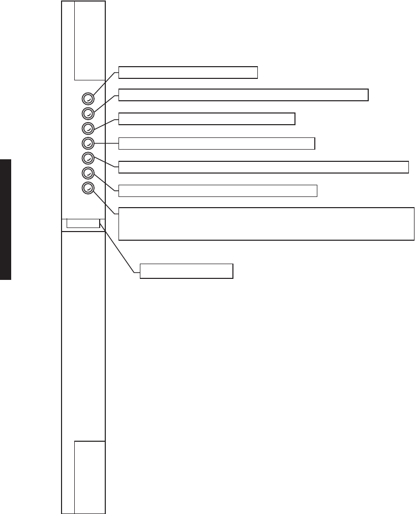
Figure 2-5 AE-37AA TMN Interface Module Controls, Indicators, and Connectors (Sheet 2 of 2)
J1
J2
J3
J4
DS1
DS2
DS3
DS4
DS5
C3A
C3B
ETH 1
UPLINK
ETH 2
ETH 3
PPP
ETHERNET 1 RJ-45 CONNECTOR
FOR UPLINK
CONNECTION TO ETHERNET HUB, SWITCH
OR ROUTER
NOTE: LEDs ARE DESIGNATED DS1-DS5
POINT-TO-POINT (PPP)
RJ-45 CONNECTOR FOR
CONNECTION TO OTHER
RADIO TMN INTFC PPP
PORTS. CAN SUPPORT
BACKHAUL CONNEC-
TION OVER CHANNEL
BANK OR SYNCHRONOUS
MODEM WITH APPROPRIATE CABLE
LMW-8047-SM
06/19/03
FLASH
CARD
PQ/ECRC
SUBBOARD
ETHERNET 2 AND 3 RJ-45 CONNECTORS
FOR NORMAL/BRIDGED CONNECTION TO
OTHER SNMP PORTS OF OTHER NEs
(RADIO, MUX, COMPUTERS)
2-12
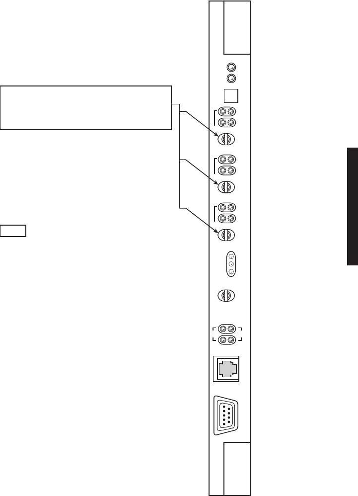
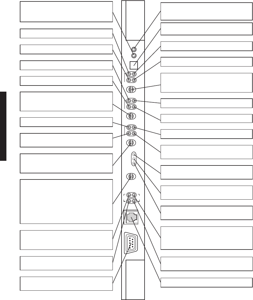
Figure 2-6 AE-37( ) Controller Controls, Indicators, and Connectors (Sheet 1 of 2)
ALM
OFF
NORM
SHLF
ALM
ALM
ON
LINE
RX
L
AB
ALM
ON
LINE
TX
L
AB
ALM
RSP
RSP
ON
LINE
I/O
L
A
POLL
LCL
RMT
B
A
C
O
/
L
T
O
V
R
D
RF RPTR
CMD
IDLE
T
E
L
U
S
I
YELLOW LED INDICATES ONE OR MORE
SOFTWARE OVERRIDES IN PROCESS OR
ONE OR MORE SWITCHES ACTIVATED.
MOMENTARY SWITCH SELECTS I/O INTFC A
(PRESS LEFT AND RELEASE) OR I/O INTFC B
(PRESS RIGHT AND RELEASE).
MOMENTARY SWITCH SELECTS RCVR A
(PRESS LEFT AND RELEASE) OR RCVR B
(PRESS RIGHT AND RELEASE).
MOMENTARY SWITCH SELECTS ALARM
CUTOFF (ACO) AND LAMP TEST (LT) (PRESS
LEFT AND RELEASE) OR OVERRIDE (OVRD)
(PRESS RIGHT AND RELEASE). LT LIGHTS ALL
LEDs ON SHELF MODULES. OVRD LATCHES
STATE OFF THE A/B TX SW, A/B RX SW, AND
A/B I/O SW AND OVERRIDES SOFTWARE
CONTROL OF ONLINE ENABLE SIGNALS.
GREEN LED FLASHING PATTERN INDICATES
STATUS OF SERVICE CHANNEL OVER THE RF
PATH IN A RING. SEE CHART FOR PATTERN.
GREEN LED INDICATES LOSS OF SERVICE
CHANNEL OVER RF PATH IN A RING.
9-PIN, D-TYPE FEMALE CONNECTOR IS USI
COMPUTER INTERFACE PORT.
RED LED INDICATES XMTR A FAILED.
GREEN LED INDICATES XMTR A IN SERVICE.
GREEN LED INDICATES RCVR A IN SERVICE.
RED LED INDICATES RCVR A FAILED.
GREEN LED INDICATES I/O INTFC A IN
SERVICE.
RED LED INDICATES I/O INTFC A FAILED.
MOMENTARY SWITCH SELECTS XMTR A
(PRESS LEFT AND RELEASE) OR XMTR B
(PRESS RIGHT AND RELEASE).
FLASHING GREEN LED INDICATES ACTIVE
POLLING.
GREEN LED INDICATES I/O INTFC B IN
SERVICE.
FLASHING GREEN LED INDICATES DATA
ACTIVITY IN RESPONSE TO LOCAL POLL.
FLASHING GREEN LED INDICATES DATA
ACTIVITY IN RESPONSE TO REMOTE POLL.
GREEN LED INDICATES LOSS OF SERVICE
CHANNEL OVER THE RPTR LINK IN A RING.
GREEN LED FLASHING PATTERN INDICATES
STATUS OF SERVICE CHANNEL OVER THE
RPTR LINK IN A RING. SEE CHART FOR
PATTERN.
RED LED INDICATES CONTROLLER FAILED.
FLASHING LED INDICATES INCORRECT
FIRMWARE LOAD.
RED LED INDICATES XMTR B FAILED.
RED LED INDICATES ANY MODULE IN SHELF
FAILED.
GREEN LED INDICATES RCVR B IN SERVICE.
RED LED INDICATES I/O INTFC B FAILED.
RED LED INDICATES RCVR B FAILED.
GREEN LED INDICATES XMTR B IN SERVICE.
STANDARD 2-WIRE TELEPHONE JACK.
LMW-3150-sm
06/12/04
2-13
Figure 2-6 AE-37( ) Controller Controls, Indicators, and Connectors (Sheet 2 of 2)
C1 ELMC OPTION KEY
EPLD PROGRAMMING CONNECTOR
(FACTORY TEST PURPOSES ONLY)
C1A
J2
P1
C1B
C1C
LMW-7047
07/18/02

2-14
Table 2-1 DS1/E1 Ring Flashing Patterns
CONTROLLER LOCATION CONTROLLER LED
RF CMD RPTR CMD RF IDLE RPTR IDLE
Scenario 1. Ring Operating Correctly
Both Ring Terminals On-long
Off-short
On-long
Off-short
On Off
All Ring Repeaters On-long
Off-short
On-long
Off-short
Off Off
Scenario 2. Failed Repeater- RF Path Failure
Both Ring Terminals On and Off
Same
On-short
Off-long
Off Off
Alarmed Ring Repeater Off On and
Off Same
On Off
All Other Ring Repeaters Off Off
Scenario 3. Failed Repeater- RPTR Link Failure
Both Ring Terminals On and Off
Same
On-short
Off-long
Off Off
Alarmed Ring Repeater On and Off
Same
Off Off On
All Other Ring Repeaters Off Off
Scenario 4. Failed Terminal- RPTR Link Failure
Alarmed Ring Terminal On and Off
Same
No Indication Off On
Associated Ring Repeater On and Off
Same
No Indication Off On
Other Ring Terminal On-short
Off-long
On-short
Off-long
Off Off
All Other Ring Repeaters Depends on
Location in Ring
Off Off
Notes:
On-long Off-short duration indicates all ring normal pattern received.
On and Off Same duration indicates ring restore pattern received.
On-short Off-long duration indicates ring fail pattern received.

2-15
Table 2-2 DS3/OC3 Ring Flashing Patterns
CONTROLLER LOCATION CONTROLLER LED
RF CMD RPTR CMD RF IDLE RPTR IDLE
Scenario 1. Ring Operating Correctly
Ring Repeater – Master Radio On-long Off-
short On-long Off-
short On Off
All Ring Repeaters – Normal Radios On-long Off-
short On-long Off-
short Off Off
Scenario 2. Failed Repeater- RF Path Failure
Ring Repeater – Master Radio On-short Off-
long On-short Off-
long Off Off
Alarmed Ring Repeater – Normal
Radio Off On and Off
Same On Off
All Other Ring Repeaters – Normal
Radio Ring Fail or
Ring Restore Ring Fail or
Ring Restore Off Off
Scenario 3. Failed Repeater- RPTR Link Failure
Ring Repeater – Master On-short Off-
long On-short Off-
long Off Off
Alarmed Ring Repeater – Normal
Radio On and Off
Same Off Off On
All Other Ring Repeaters – Normal
Radios Ring Fail or
Ring Restore Ring Fail or
Ring Restore Off Off
Scenario 4. Failed Master- RPTR Link Failure
Alarmed Ring – Master Radio On-long Off-
short Off Off On
Associated Ring Repeater – Normal
Radio On and Off
Same Off Off On
All Other Ring Repeaters – Normal
Radios Ring Fail or
Ring Restore Ring Fail or
Ring Restore Off Off
Notes:
On-long Off-short duration indicates all ring normal pattern received.
On and Off Same duration indicates ring restore pattern received.
On-short Off-long duration indicates ring fail pattern received.
2-16
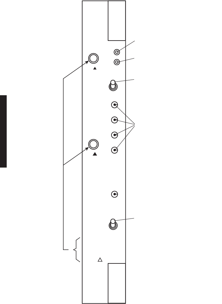
Figure 2-7 CE-16BB Power Supply Controls, Indicators, Test Points, and Connectors (Sheet 1 of 2)
ALARM
RED LED INDICATES INTERNAL
FAILURE OR BLOWN FUSE.
YELLOW LED INDICATES PA ON/OFF
SWITCH IS SET TO OFF.
FACTORY TEST POINTS FOR
POWER SUPPLY VOLTAGES.
2-POSITION TOGGLE SWITCH
APPLIES POWER TO POWER SUPPLY
(ON 1) OR REMOVES POWER (OFF 0).
ON 1
POWER
OFF 0
ON
PA
OFF
+10.5V
+12V
-5V
-12V
GND
OFF
NORM
LMW-7048-sm
06/12/04
2-POSITION TOGGLE SWITCH
APPLIES POWER TO PA (IF EQUIPPED)
(ON) OR REMOVES POWER (OFF).
CAUTION:
TIGHTEN MOUNTING
SCREWS BEFORE
APPLYING POWER
2 PLACES
MARKED
2-17
Figure 2-7 CE-16BB Power Supply Controls, Indicators, Test Points, and Connectors (Sheet 2 of 2)
SPARES
SIDE VIEW OF POWER SUPPLY
F1 F2
A
B
15A FAST BLO
PN 264-0928-130
LMW-3160-sm
08/15/02
2-18
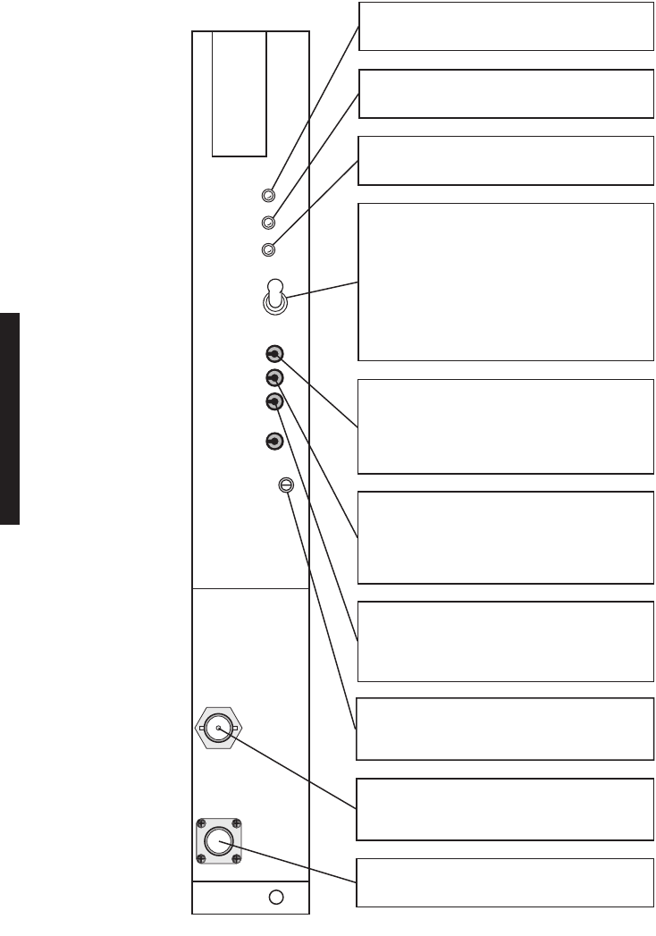
Figure 2-8 DX-35M DS1 I/O Interface Controls and Indicators
RCV
I/O
ALM
ON
LINE
SYNC
ALM
ALM
ON
LINE
COMMON
LOSS
ALM
RED LED INDICATES LOSS OF SIGNAL, DETECTION
OF BIPOLAR VIOLATION, OR FAILURE OF ACTIVE
DS1/E1 LINE(S).
RED LED INDICATES FRAME LOSS OR CHANNEL
FAIL ALM IN A AND B RCVR CIRCUITS. USUALLY
INDICATES FAR-END XMTR ALM.
RED LED INDICATES XMT SYNC FAILURE
BETWEEN I/O INTERFACE MODULES.
RED LED INDICATES LOSS OF RCV FRAME SYNC.
GREEN LED INDICATES RCVR IN SERVICE.
GREEN LED INDICATES I/O IN SERVICE.
LMW-7051-sm
08/15/02
2-19
Figure 2-9 DX-35N DS3 I/O Interface Controls and Indicators
XMT
AUX
SC
ALM
RCVR
ON
RAD
LOF
WYSD
DS1
WYSD
ALM
DS3
ALIGN
RAD DADE
GREEN LED INDICATES AUXILIARY XMT CIRCUITS
ARE ENABLED. ALLOWS TRANSFER OF DATA TO
DS1/E1 INTFC CIRCUITS.
RED LED INDICATES LOSS OF FRAME DETECTED
IN WAYSIDE DS1/E1 INTFC RCV CIRCUIT.
10-POSITION ROTARY SWITCH ADJUSTS DELAY
BETWEEN MAIN AND DIVERSITY RCV PATHS IN
SPACE DIVERSITY CONFIGURATION.
POTENTIOMETER ADJUSTS
DADE BETWEEN A AND B SYNC
PULSES FOR LINE 1 FOR
ERRORLESS SWITCHING.
DS3 ALIGN 3 TEST POINT
DS3 ALIGN 2 TEST POINT
DS3 ALIGN 1 TEST POINT
RADIO DADE TEST POINT
POTENTIOMETER ADJUSTS
DADE BETWEEN A AND B SYNC
PULSES FOR LINE 2 FOR
ERRORLESS SWITCHING.
POTENTIOMETER ADJUSTS
DADE BETWEEN A AND B SYNC
PULSES FOR LINE 3 FOR
ERRORLESS SWITCHING.
CHASSIS GROUND TEST POINT
GREEN LED INDICATES RCV CIRCUITS ARE
ENABLED. ALLOWS TRANSFER OF DATA TO
ENCODER/DECODER CIRCUITS.
RED LED INDICATES SERVICE CHANNEL FRAME
LOSS DETECTED IN RCV CIRCUITS.
GREEN LED INDICATES WAYSIDE DS1/E1 INTFC
CIRCUITS OUTPUT DRIVERS ARE ENABLED.
RED LED INDICATES RADIO LOSS OF FRAME
DETECTED IN RCV CIRCUITS.
LMW-3137-sm
06/12/04
1
2
3
5
6
7
8
9
0
1
2
3
4
2-20
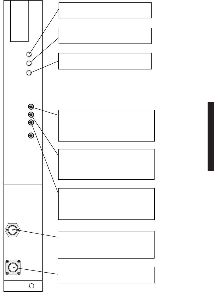
Figure 2-10 DX-35P OC3 I/O Interface Controls and Indicators
RED LED INDICATES MODULE FAILURE.
GREEN LED INDICATES XMT AND/OR RCV CIRCUITS ARE PASSING DATA.
GREEN LED INDICATES OC3 DATA ON INPUT TO OPTICAL RCV/RADIO XMT CIRCUITS.
YELLOW LED INDICATES OPTICAL RCV CIRCUIT FAILURE.
GREEN LED INDICATES WAYSIDE DS1 IN SERVICE.
YELLOW LED INDICATES WAYSIDE DS1 SIGNAL FAILURE.
GREEN LED INDICATES OUTPUT LASER IS ON. ON 4-FIBER SYSTEMS, LASERS ON
BOTH A AND B I/O INTERFACE ARE ALWAYS ON. ON 2-FIBER SYSTEMS, LASER ON A
OR B IS ON.
LMW-4011-sm
08/15/02
LC OPTICAL CONNECTOR
ALM
INSVC
OC3
IN
OC3
ALM
WYSD
ON
WYSD
ALM
OC3
OUT
2-21
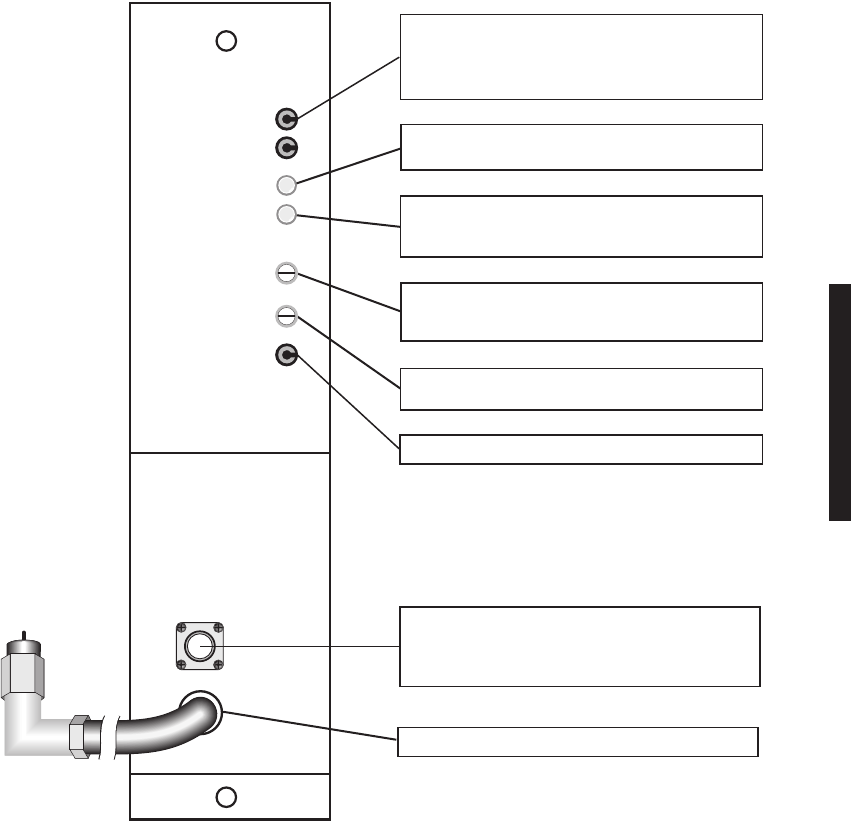
Figure 2-11 UD-35( ) Transmitter Controls, Indicators, Test Points, and Connectors
PWR MON
XMT PWR
ALM
ON LINE
I CARR NULL
XMT LVL
ADJ
FREQ CONT
Q CARR NULL
TRANSMITTER
RF
OUT
XTAL
MON
RF
MON
MW211-0017-1
03/29/03
ADJUSTS I–CHANNEL CARRIER SUPPRESSION.
ADJUSTS Q–CHANNEL CARRIER SUPPRESSION.
ADJUSTS RF OUTPUT POWER
AT OUTPUT OF XMTR (AND PA, IF EQUIPPED).
RED LED INDICATES XMTR POWER LOSS.
MONITOR POINT TO MEASURE XMT OUTPUT
SIGNAL LEVEL (SMA, FEMALE).
RF OUTPUT CONNECTOR (SMA, FEMALE).
GREEN LED INDICATES XMTR IN SERVICE.
ADJUSTS FUNDAMENTAL FREQ
OF CRYSTAL OSCILLATOR.
NULLS RF
CARRIER
MONITORS RF
OUTPUT
DETECTED DC
MONITOR POINT TO MEASURE FUNDAMENTAL
CRYSTAL FREQ (MHz) (BNC, FEMALE).
2-22
Figure 2-12 DS1/E1 UD-36( ) Receiver (Obsolete Version With Pedestal Switch) Controls,
Indicators, Test Points, and Connectors
RED LED INDICATES LOSS OF LOCK
FROM RECEIVE SIGNAL.
YELLOW LED INDICATES DEGRADED
RECEIVE SIGNAL.
GREEN LED INDICATES RCVR IN
SERVICE.
MONITOR POINT TO MEASURE DC
CONTROL VOLTAGE USED TO CONTROL
LO FREQ. SAME VOLTAGE IS DISPLAYED
ON RX (AFC MON) FIELD ON ANALOG
MONITOR SCREEN.
MONITOR POINT TO MEASURE DC
VOLTAGE INDICATING QUALITY OF
RECEIVE BASEBAND SIGNALS. SAME
VOLTAGE IS DISPLAYED ON RX (EYE MON)
FIELD ON ANALOG MONITOR SCREEN.
MONITOR POINT TO MEASURE DC
VOLTAGE PROPORTIONAL TO RSL. SAME
VOLTAGE IS DISPLAYED ON RX (RSL MON)
FIELD ON ANALOG MONITOR SCREEN.
MONITOR POINT TO MEASURE
FUNDAMENTAL CRYSTAL FREQ (MHz)
(BNC, FEMALE).
RF INPUT CONNECTOR
(SMA, FEMALE).
CHAN ALM
EYE
CLOSURE
ON LINE
AFC MON
EYE MON
RSL MON
GND
FREQ
CONT
RECEIVER
XTAL
MON
RF
IN
LMW-6089-sm
08/15/02
2-POSITION TOGGLE SWITCH SETS AFC
TO NORMAL (NORM) OR PEDESTAL (PED).
NORM
POSITION LOCKS RCVR TO
FAR-END XMTR.
RX (AFC MON)
VOLTAGE
DISPLAYED ON ANALOG MONITOR SCREEN
TRACKS AFC VOLTAGE.
PED
POSITION
DISABLES AFC AND LOCKS RCVR TO FIXED
VOLTAGE (SETS RCV LO ON FREQ WITHOUT
PHASE LOCK).
ADJUSTS FREQ OF CRYSTAL OSCILLATOR
.
ONLY WITH AFC PED/NORM SWITCH IN
PED POSITION.
PED
AFC
NORM
2-23
Figure 2-13 UD-36( ) DS1/E1/DS3/OC3 Single Receiver Controls, Indicators,
Test Points, and Connectors
RED LED INDICATES LOSS OF LOCK
FROM RECEIVE SIGNAL.
YELLOW LED INDICATES DEGRADED
RECEIVE SIGNAL.
GREEN LED INDICATES RCVR IN
SERVICE.
MONITOR POINT TO MEASURE DC CON-
TROL VOLTAGE USED TO CONTROL LO
FREQ. SAME VOLTAGE IS DISPLAYED ON
RX (AFC MON) FIELD ON ANALOG MONITOR
SCREEN.
MONITOR POINT TO MEASURE DC VOL-
TAGE INDICATING QUALITY OF RECEIVE
BASEBAND SIGNALS. SAME
VOLTAGE IS
DISPLAYED ON
RX (EYE MON)
FIELD ON
ANALOG MONITOR SCREEN.
MONITOR POINT TO MEASURE DC VOL-
TAGE PROPORTIONAL TO RSL. SAME
VOLTAGE IS DISPLAYED AS DBM ON RX
(RSL 1) dBm FIELD ON ANALOG MONITOR
SCREEN.
MONITOR POINT TO MEASURE
FREQ
RCVR IS LOCKING
ON (RCVR LOCKS ON
XTAL FREQ OF ASSOCIATED UPSTREAM
XMTR) (BNC, FEMALE).
RF INPUT CONNECTOR
(SMA, FEMALE).
CHAN ALM
EYE
CLOSURE
ON LINE
AFC MON
EYE MON
RSL MON
GND
RECEIVER
XTAL
MON
RF
IN
LMW-3171-sm
06/12/04
2-24
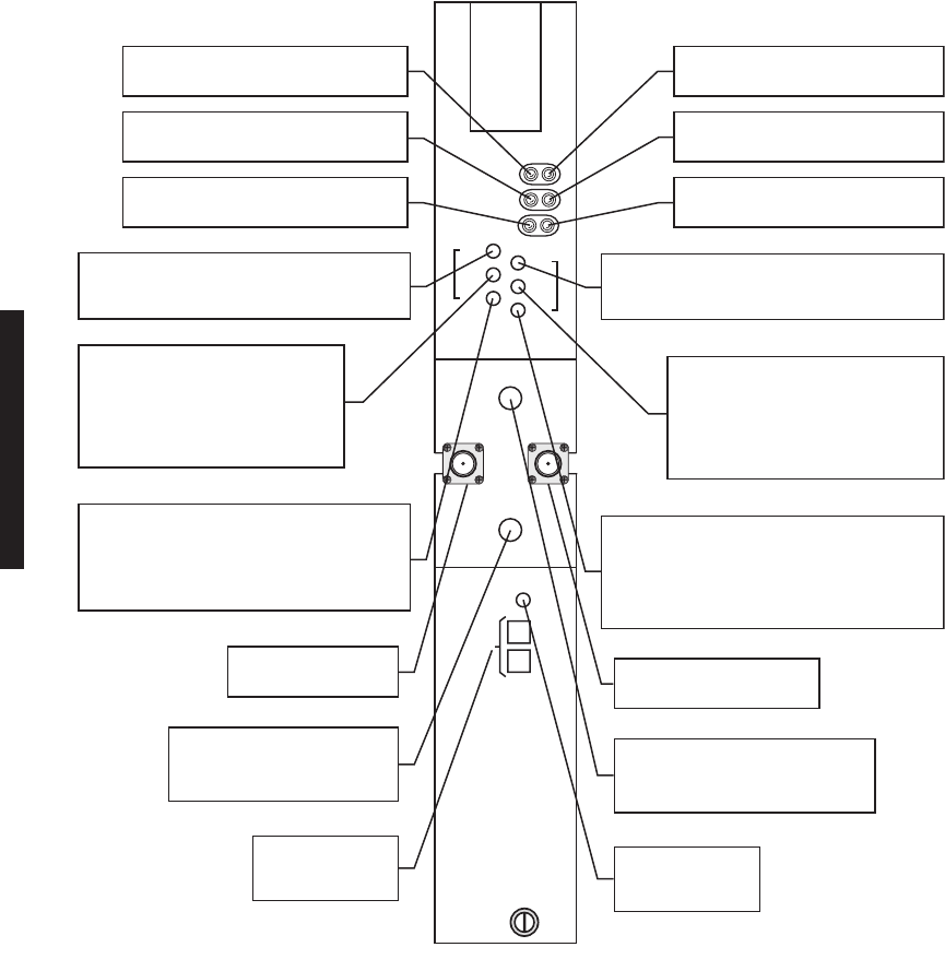
Figure 2-14 UD 36( ) Dual Receiver Controls & Indicators, Test Points and Connectors
CHANNEL ALM
MNDV
EYE CLOSURE
ON LINE
AFC
EYE
RSL
M
A
I
N
AFC
EYE
RSL
D
I
V
E
R
S
I
T
Y
GND
XTAL DV
XTAL MN
DUAL RECEIVER
LMW-9033-sm
06/12/04
RF IN
DV
RF IN
MN
MONITOR POINT TO MEASURE DC CON-
TROL VOLTAGE USED TO CONTROL MAIN
LO FREQ.
MONITOR POINT TO MEASURE DC
VOLTAGE INDICATING QUALITY OF
MAIN RECEIVE BASEBAND SIGNALS.
SAME VOLTAGE IS DISPLAYED ON
RX (EYE MON) (MN) FIELD ON
ANALOG MONITOR SCREEN.
MONITOR POINT TO MEASURE DC VOLTAGE
PROPORTIONAL TO MAIN RSL. SAME VOL-
TAGE IS CONVERTED TO dBm, AND dBm
LEVEL IS DISPLAYED IN
RX (RSL) (MN)
FIELD
ON ANALOG MONITOR SCREEN.
RED LED INDICATES LOSS OF
LOCK ON MAIN RECEIVE SIGNAL.
GREEN LED INDICATES MAIN RCVR
IN SERVICE.
MAIN RF INPUT CABLE
(SMA FEMALE)
MONITOR POINT TO MEASURE
MAIN FUNDAMENTAL CRYSTAL
FREQ (MHz) (SMA FEMALE)
YELLOW LED INDICATES
DEGRADED MAIN RECEIVE SIGNAL.
MONITOR POINT TO MEASURE DC CONTROL
VOLTAGE USED TO CONTROL DIVERSITY LO
FREQ.
MONITOR POINT TO MEASURE DC
VOLTAGE INDICATING QUALITY OF
DIVERSITY RECEIVE BASEBAND
SIGNALS. SAME VOLTAGE IS DIS-
PLAYED ON RX (EYE MON) (DV) FIELD
ON ANALOG MONITOR SCREEN.
MONITOR POINT TO MEASURE DC VOLTAGE
PROPORTIONAL TO DIVERSITY RSL. SAME
VOLTAGE IS CONVERTED TO dBm, AND dBm
LEVEL IS DISPLAYED IN
RX (RSL) (DV)
FIELD ON
ANALOG MONITOR SCREEN.
RED LED INDICATES LOSS OF LOCK
ON DIVERSITY RECEIVE SIGNAL.
GREEN LED INDICATES DIVERSITY
RCVR IN SERVICE.
DIVERSITY RF INPUT CABLE
(SMA FEMALE)
MONITOR POINT TO MEASURE
DIVERSITY FUNDAMENTAL CRYSTAL
FREQ (MHz) (SMA FEMALE)
TEST GROUND
POINT
FACTORY USE
CONNECTOR
YELLOW LED INDICATES DEGRADED
DIVERSITY RECEIVE SIGNAL.
2-25
Figure 2-15 UD-51( ) Power Amplifier Controls, Indicators, Test Points, and Connectors
MW211-0038-1-sm
04/29/03
DC MON
GND
10.5V DC
PWR ALM
TEMP ALM
DC MON ADJ
PWR ALM ADJ
POWER AMPLIFIER
RF
IN
RF
MON
FACTORY ADJUST ONLY
MONITOR POINT TO MEASURE DC VOLTAGE
REPRESENTATIVE OF OUPUT POWER
(0.1V DC PER DB OF RF OUTPUT SIGNAL FOR
NOMINAL POWER ONLY)
RED LED INDICATES RF PWR IS ABOVE OR BE-
LOW ALARM THRESHOLD SET BY PWR ALM ADJ.
YELLOW LED INDICATES HIGH TEMP ON PA
(MAY BE CAUSED BY IMPROPER MOUNTING
TO HEATSINK).
ALLOWS USER TO ADJUST VOLTAGE AT DC MON
TEST POINT (0.1V DC PER DB OF RF OUTPUT
SIGNAL IS TYPICAL)
MONITOR POINT TO MEASURE 10.5V DC INPUT
MONITOR POINT TO MEASURE/CALIBRATE RF
OUTPUT SIGNAL AT TOP OF STACK
(SMA, FEMALE) (APPROX. 30 DB DOWN FROM
RF OUTPUT)
RF INPUT CABLE (SMA MALE)
2-26
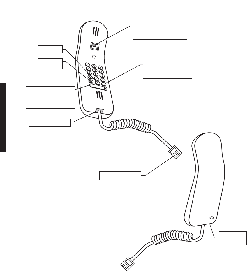
Figure 2-16 Handset Controls, Indicators, Test Points, and Connectors
NOT USED
R
NOT USED
ON-HOOK/OFF-HOOK
SWITCH - PUSH FROM
LEFT TO RIGHT TO
TALK AND LISTEN
BIS BUTTON - PRESS
TO CALL LAST
NUMBER DIALED
FV/DC SWITCH
SET TO FV FOR
MDR-8000 APPLICATION
RJ11 CONNECTOR
RJ11 CONNECTOR
OFF-HOOK
INDICATOR
REAR VIEW
FRONT VIEW
LMW-3006-sm
8/15/02

3-1
3
INTERCONNECT
3.1
SECTION INTRODUCTION
This section gives the location and describes strapping, power connections, signal connec-
tions, status and alarm connections, and service channel connections. For further details,
refer to the complete instruction book on the attached CD ROM.
3.2
INSTALL POWER CABLE ASSEMBLIES
See Figure 3-1 for power cable assembly installation procedures. The MDR-8000 is internally
wired to accept 20.5 to 60 V dc input power with positive or negative ground. To protect main-
tenance personnel from lightning strikes, the ground system must be integrated by bonding
station ground and dc battery return together. The dc power connectors J1 and J2 are located
on the rear of the back panel. Install power cables as shown.
Short circuiting low-voltage, low-impedance dc circuits can
cause arcing that may result in burns or eye injury. Remove
rings, watches, and other metal jewelry while working with
primary circuits. Exercise caution to avoid shorting input
power terminals.
To protect maintenance personnel from antenna tower light-
ning strikes, the ground system must be integrated by bond-
ing frame ground and dc battery return together.
Do not apply battery power until it is determined that A and
B battery cables with isolated returns and power cables are
wired correctly. With power applied, reverse polarity on wir-
ing (+batt wired to -batt pin on connector) can cause power
supply fuse to blow.
DANGER
Possibility of
Injury
to Personnel
DANGER
Possibility of
Injury
to Personnel
WARNING
Possibility of
Damage
to Equipment
3-2
Grounding of pole, antenna, customer interfaces, and all entrances to
the building interior shall meet local electrical code and standard busi-
ness practices.
Figure 3-1 Power Cable Assembly Installation
Note
PIN 1
POS
PIN 2
GND
J1
(J2 ON OPPOSITE
END OF SHELF)
PWR CABLE ASSEMBLY
PN 695-7845-005/009
SLIDE-ON
LUG
RED
12 AWG
LMW-3103-sm
03/25/03
CHASSIS
GND
– BATT
+ BATT
CONNECT + BATT WIRE
TO + RACK GND FOR
POS GND INSTALLATIONS CONNECT – BATT WIRE
TO – RACK GND FOR NEG
GND INSTALLATIONS
PIN 3
NEG
ORN
12 AWG
ORN
BLK
RED
BLK
12 AWG
1. DETERMINE IF INSTALLATION
REQUIRES POS OR NEG GND.
2. INSTALL BATT, GND, AND JUMPER
WIRES ON PWR CABLE ASSEMBLY.
3. CONNECT PWR CABLE ASSEMBLY
TO J1 (AND J2 IF HOT-STBY).
4. CONNECT RACK GND AND
CHASSIS GND.
5. CONNECT BATT.
REAR VIEW OF SHELF
3-3
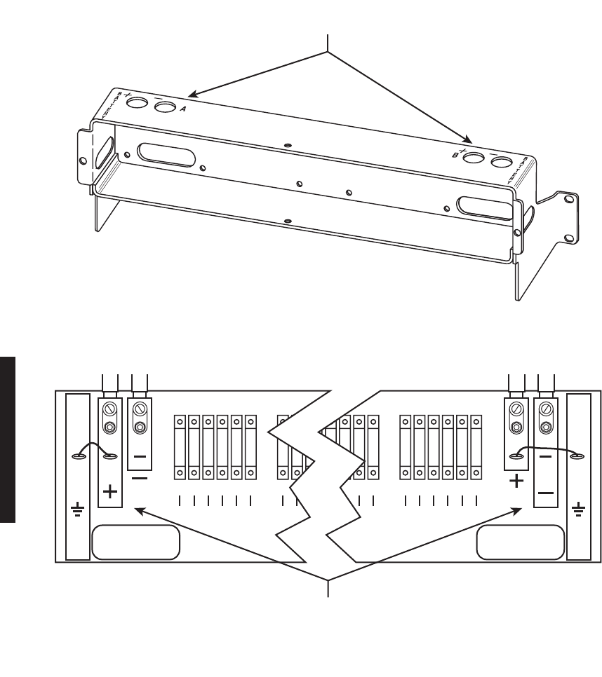
3.3
PDU STRAPPING AND CONNECTIONS
Figure 3-2 PDU (695-6200-001/002) Strapping and Connections (Sheet 1 of 2)
–+ –+
B BATTA BATT
TOP VIEW
STRAP E7 TO E15 FOR
POSITIVE INPUT VOLTAGE.
STRAP E8 TO E15 FOR
NEGATIVE INPUT VOLTAGE.
STRAP J2D TO J2C TO J2B
FOR 24V OPERATION.
STRAP J2A TO J2B TO J2D
FOR 48V OPERATION.
JUMPER E2 TO E3 AND E5 TO E6 FOR POSITIVE RACK GND.
JUMPER E1 TO E2 AND E4 TO E5 FOR NEGATIVE RACK GND.
ALSO, MOVE CHASSIS GND TO AGREE WITH RACK GND POLARITY.
SEE FIGURE 3-1, POWER CABLE ASSEMBLY INSTALLATION,
AND APPLICATION DWG 3DH031770000 EJZZA.
POWER DISTRIBUTION PANEL
FRONT VIEW – PANEL REMOVED
R3
E7
2C
2B
2A
2D
E5E2
E1 E3 E4 E6
TB4
TB3
TB2
TB1
E15
E8
CIRCUIT BOARD LOCATED INSIDE
POWER DISTRIBUTION PANEL
FRONT VIEW
NEG
'A' BATTERY
-24/-48
POS
'A' BATTERY
+24/+48
NEG
'B' BATTERY
-24/-48
POS
'B' BATTERY
+24/+48
BATTERY INPUT
WIRE SIZE NO. 4 (MAX)
LMW-7029-sm
07/12/02
rev 03/25/03
3-4
Figure 3-2 PDU (3EM13317AA) Strapping and Connections (Sheet 2 of 2)
6
E19
5
E20
4
E21
3
E22
2
E23
1
E24
FUSES
1
E1
2
E2
3
E3
4
E4
5
E5
6
E6
FUSES
BATTERY BATTERY BATTERY BATTERY
A+ A- B+ B-
LMW-9001
04/22/03
E42 E40 E41
E37
E39E38
1
E7
2
E2
3
E3
FUSES
5
4
4
E15
3
E16
2
E17
1
E18
FUSES
JUMPER E39 TO E38 AND E42 TO E41 FOR
POSITIVE RACK GND (AS SHOWN ABOVE).
JUMPER E37 TO E38 AND E40 TO E41 FOR
NEGATIVE RACK GND. FOR DETAILED WIRING
INFORMATION, SEE APPLICATION DWG
3DH031770000 EJZZA.
POWER DISTRIBUTION UNIT
ISOMETRIC VIEW – CIRCUIT BOARD
AND FRONT PANEL REMOVED
BATTERY INPUT
WIRE SIZE NO. 4 (MAX)
CIRCUIT BOARD
LOCATED INSIDE PDU

3-5
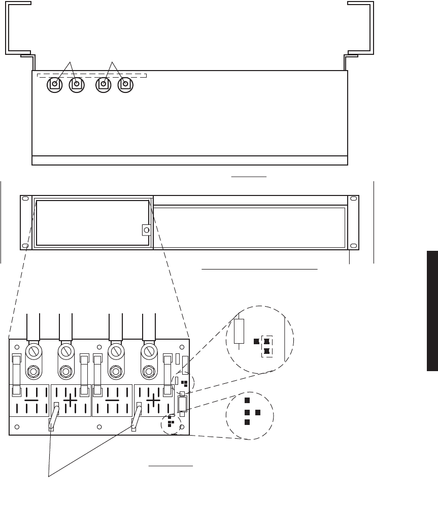
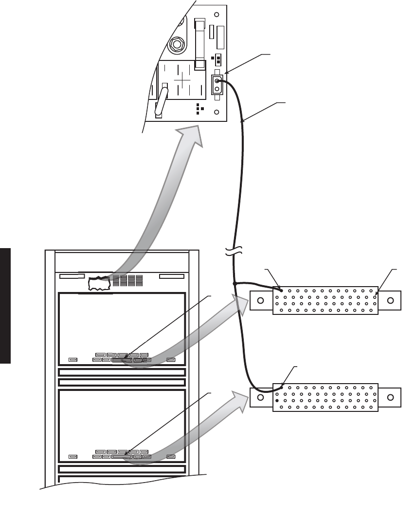
3.4
SHELF/RACK ALARM CONNECTION
Each MDR-8000 rack equipped with the Power Distribution Unit (PDU) 695-6200-001/002
has a visual rack alarm indicator to report a shelf failure. In order to activate a rack alarm
visual indicator on the PDU, the shelf alarm output from each MDR-8000 shelf must be
hardwired to connector J1 on the PDU. The shelf alarm is provided on alarm connector
J305 pin 24 (major/visual alarm). A wire-wrap adapter (PN 695-4171-002) for connector
J305 is available. Insulated 22-gauge solid copper wire is recommended for connecting to
the wire-wrap adapter. To attach to J1 (2-pin connector) on the PDU, use 2-position socket
housing PN 372-0114-140 and socket contact PN 372-0114-390. See Figure 3-3, sheet 1,
for shelf-to-rack alarm wiring.
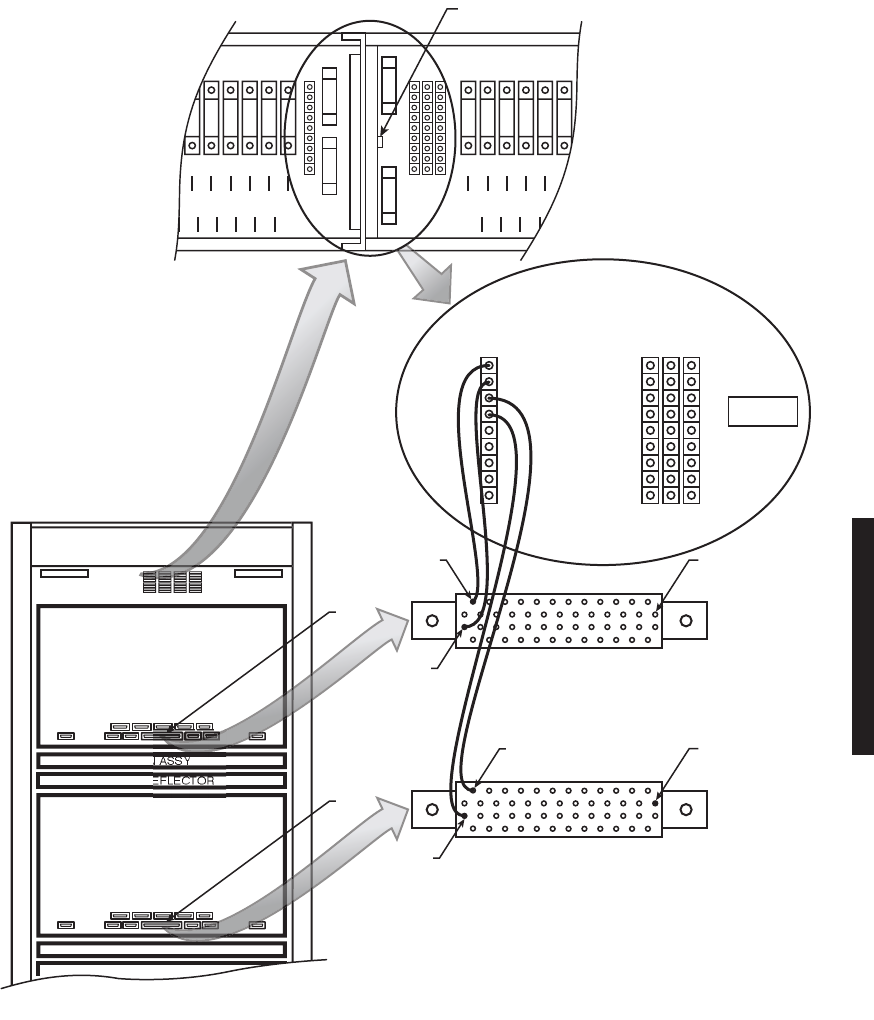
Each MDR-8000 rack equipped with PDU 3EM13317AA has a blown fuse alarm visual
indicator and a Form C relay alarm output (J4, J5, and J6) for connection to customer
alarm equipment.
An optional Fuse and Shelf alarm plug-in assembly is available to provide shelf alarm connec-
tions requiring Form C relays. The alarm inputs (major and minor) must be hard wired to J3
on the PDU. The alarms are provided on alarm connector J305 pin 24 (major/visual alarm) and
pin 50 (minor/audible alarm) of each shelf. A wire-wrap adapter (PN 695-4171-002) for connec-
tor J305 is available. Insulated 22-gauge solid copper wire is recommended for connecting to
the wire-wrap adapter and also to J3 on the PDU. Alarm outputs are transmitted to customer
equipment via Form C relay outputs (J4, J5, J6, relays 1 through 8). This option also includes
the blown fuse alarm indicator and Form C relay alarm output (J4, J5, and J6 – relay 9). See
Figure 3-3, sheet 2, for shelf to PDU alarm wiring.
3-6
Figure 3-3 Shelf Alarm Wiring PDU (695-6200-001/002) (Sheet 1 of 2)
E4
E5
E30
E31
E32
E33
J2C
E8
R1
R2
E7
E15
F4
J2B
J2A
J2D
E34
MDR-8000 SHELF
FAN ASSY
HEAT DEFLECTOR
MDR-8000 SHELF
FAN ASSY
PDU
J305
J305
PIN 1
24
24
TO ATTACH USE:
2 - POSITION SOCKET HOUSING:
PN 372-0114-140
AND SOCKET CONTACT:
PN 372-0114-390
WIRE WRAP ADAPTER
(PN 695-4171-002)
MAJOR / VISUAL ALM
MAJOR / VISUAL ALM
ABAM CABLE
PN 424-0429-030
LMW-7070-sm
07/24/02
3-7
Figure 3-3 Shelf Alarm Wiring PDU (3EM13317AA) (Sheet 2 of 2)
MDR-8000 SHELF
FAN ASSY
HEAT DEFLECTOR
MDR-8000 SHELF
FAN ASSY
PDU
J305
J305
PIN 1
PIN 1
24
50 WIRE WRAP ADAPTER
WIRE WRAP
24
50
LMW-8057-SM
04/23/03
6
E13
5
E14
4
E15
3
E16
2
E17
1
E18
E31 E32 E33 E34 E35 E36
FUSES
1
E7
2
E8
3
E9
4
E10
5
E11
6
E12
E25 E26 E27 E28 E29 E30
FUSES
RACK GND RACK GND
20 AMP
20 AMP
20 AMP
20 AMP
10 AMP
10 AMP
20 AMP
20 AMP
10 AMP
1 AMP1 AMP
1 AMP1 AMP
10 AMP
20 AMP
20 AMP
1
2
3
4
5
6
7
8
FUSE ALM
1
2
3
4
5
6
7
8
NC COM NO
J5
ALARM OUTPUTALARM INPUT
J4 J6
MAJOR 1
MINOR 1
MAJOR 2
MINOR 2
MAJOR 3
MINOR 3
MAJOR 4/AUX
MINOR 4/AUX
UNUSED
J3
CUSTOMER
OUTPUTS
FUSE ALARM INDICATOR
3-8
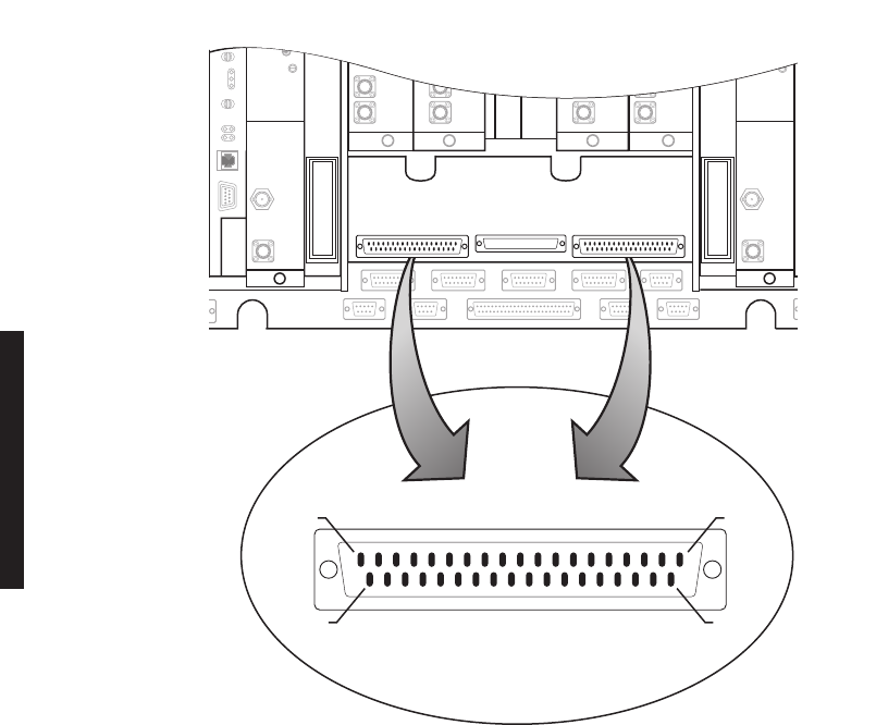
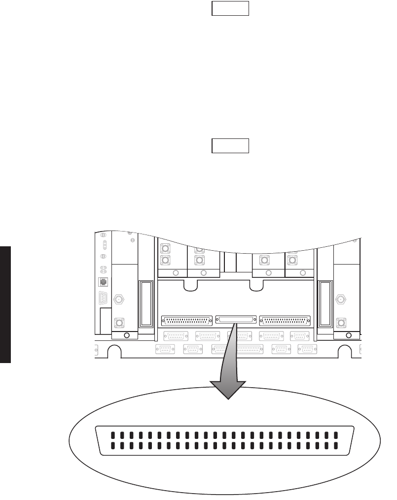
3.5
DS1 CONNECTIONS (J303 IN AND J304 OUT)
Recommended connectorized cable assembly – PN 695-7806-001 through -005 (22 AWG 16 pair
shielded, jacketed cable with 37-pin D-type connector on one end). See Figure 3-4 for shelf con-
nector location and pinout. Refer to Table 3-1 for mating cable wiring and color code.
Figure 3-4 DS1 Connectors Location and Pinout
J303/J304
FRONT VIEW
LBO
37
19
20
LMW-9037
05/29/03
1

3-9
Table 3-1 DS1 IN J303 and DS1 OUT J304 Pinout Assignments
CONNECTOR PIN
NUMBER WIRE COLOR SIGNAL NAME CABLE PAIR NUMBER
1 WHITE–BLUE CHAN 1 TIP 1
20 BLUE–WHITE CHAN 1 RING
2 WHITE–ORANGE CHAN 2 TIP 2
21 ORANGE–WHITE CHAN 2 RING
3 WHITE–GREEN CHAN 3 TIP 3
22 GREEN–WHITE CHAN 3 RING
4 WHITE–BROWN CHAN 4 TIP 4
23 BROWN–WHITE CHAN 4 RING
5 WHITE–SLATE CHAN 5 TIP 5
24 SLATE–WHITE CHAN 5 RING
6 RED–BLUE CHAN 6 TIP 6
25 BLUE–RED CHAN 6 RING
7 RED–ORANGE CHAN 7 TIP 7
26 ORANGE–RED CHAN 7 RING
8 RED–GREEN CHAN 8 TIP 8
27 GREEN–RED CHAN 8 RING
9 RED–BROWN CHAN 9 TIP 9
28 BROWN–RED CHAN 9 RING
10 RED–SLATE CHAN 10 TIP 10
29 SLATE–RED CHAN 10 RING
11 BLACK–BLUE CHAN 11 TIP 11
30 BLUE–BLACK CHAN 11 RING
12 BLACK–ORANGE CHAN 12 TIP 12
31 ORANGE–BLACK CHAN 12 RING
13 BLACK–GREEN CHAN 13 TIP 13
32 GREEN–BLACK CHAN 13 RING
14 BLACK–BROWN CHAN 14 TIP 14
33 BROWN–BLACK CHAN 14 RING
15 BLACK–SLATE CHAN 15 TIP 15
34 SLATE–BLACK CHAN 15 RING
16 YELLOW–BLUE CHAN 16 TIP 16
35 BLUE–YELLOW CHAN 16 RING
3-10
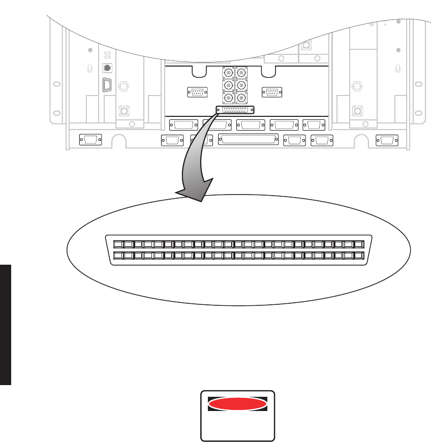
3.6
DS1 REPEATER (J314 ON ONE SHELF TO J314 ON SECOND SHELF)
The DS1 repeater cable carries clocks, DS1 data, and overhead for two
directions. If the 314 cable is not used, the embedded data in the over-
head must be cabled individually. In this case, individual cables must
be run for MCS–11, audio, RS-232, and ELMC.
Recommended connectorized cable assembly – PN 695-7836-001/005 (25 pair shielded cable
with 50 pin Amp connectors) (SCSI). See Figure 3-5 for shelf connector location and pinout.
Refer to the Interconnect Section on attached CD for mating cable wiring and color code.
Use repeater cables for cabling repeater shelf 1 to repeater shelf 2 (east-
bound/westbound data/clock)
Figure 3-5 Connector J314 Location – DS1 LBO
Note
Note
LBO
LMW-9038
05/29/03
25
50
PIN 1
J314
26
FRONT VIEW
3-11
3.7
DS3 LBO STRAPPING AND CONNECTIONS
The DS3 LBO compensates for the distance to the cross-connect for DS3 and wayside DS1
outputs. See Figure 3-6 for strap locations. Refer to Table 3-2 for strapping requirements.
Figure 3-6 DS3 LBO Strapping
When using 734 or equivalent type DS3 cable, 450 feet is the maximum
length to the cross-connect. The maximum length with the LBO
strapped IN is 225 feet.
Table 3-2 DS3 LBO Strapping
OUTPUTS DISTANCE TO CROSS-CONNECT STRAPPING
DS3 0 to 225 ft In
DS3 226 to 450 ft Out
Wayside DS1 0 to 330 ft In
Wayside DS1 331 to 660 ft Out
LMW-3149B-sm
07/27/02
LBO
OUT
IN
LBO
OUT
IN
LBO
OUT
IN
LBO
OUT
IN
IN/OUT STRAPPING
FOR
DS3 LINES
IN/OUT STRAPPING
FOR
WAYSIDE DS1 LINES
DS3 LINE 2
DS3 LINE 1
DS3 LINE 3
WAYSIDE LINE 2
WAYSIDE LINE 3
WAYSIDE LINE 1
Note
3-12
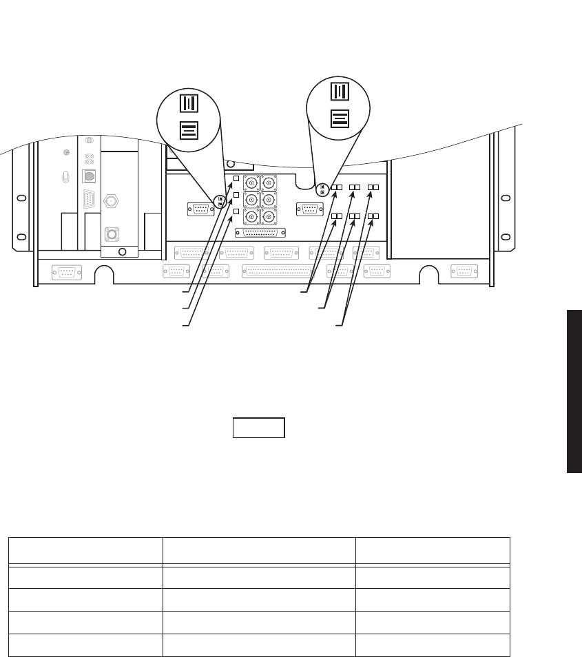
3.8
DS3 LBO DS3 BNC CONNECTIONS (J21 THROUGH J26)
BNC removal tool (PN 359-0092-010) is required for installing and removing BNC cables.
Recommended connectorized cable assembly for all applications except repeaters, PN 632-
4429-096/180 (8/15 ft RG-59B/U coax cable with straight male BNC connector on one end
and right angle male BNC connector on other end). For repeater applications, recommend
PN 632-4288-096/180 (8/15 ft RG-59B/U coax cable with straight male BNC connector on
each end). See Figure 3-7 for locations. Refer to Table 3-3 for connections.
Figure 3-7 DS3 LBO DS3 Connectors Location
J315
J301
J313
J308 J309 J310 J312
J318 J305 J316 J317 J302
J307
LMW-7065-sm
07/23/02
LINE 1 OUT – J21
LINE 2 OUT – J23
LINE 3 OUT – J25
J22 – LINE 1 IN
J24 – LINE 2 IN
J26 – LINE 3 IN
FRONT VIEW

3-13
3.9
DS3 LBO WAYSIDE DS1 CONNECTIONS (J201 IN AND J202 OUT)
Wayside DS1 is an option in the MDR-8000 DS3 radios. This option provides 1 DS1 for
each equipped DS3. To activate the wayside channels requires a small circuit board, called
ELMC option key, that plugs onto the controller module. The protection of the wayside
channels follows the protection scheme of the radio configuration. In other words, if the
radio is hot-standby the wayside channels are hot-standby. The channels are point to point
just as is the payload traffic. They are independent of the traffic and reside in the overhead
channels. The advantage of the wayside DS1 is the ability to drop 1 to 3 DS1’s without hav-
ing to add a 1:3 muldem to access the traffic. Refer to Table 3-4 for ELMC option key
requirements for remote monitoring/controlling wayside DS1s.
Table 3-3 DS3 LBO Connectors
DS3 INPUTS DS3 OUTPUTS
FUNCTION BNC CONNECTOR FUNCTION BNC CONNECTOR
DS3 LINE 1 J22 DS3 LINE 1 J21
DS3 LINE 2 J24 DS3 LINE 2 J23
DS3 LINE 3 J26 DS3 LINE 3 J25
Table 3-4 Wayside DS1 Performance and Control
PART NO. FUNCTION
ELMC Option Key 695-5647-019 Required to enable WS DS1 lines for remote way-
side DS1status
ELMC Option Key 695-5647-020 Required to enable WS DS1 lines for remote way-
side DS1status + remote provisioning and down-
loading
3-14
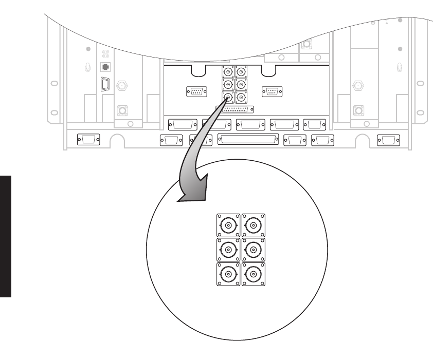
3.9.1
Wayside DS1 Terminal
Recommended connectorized cable assembly – PN 695-4125-041 (26 AWG 5 pair shielded,
jacketed cable with 9-pin D-type connector on one end). See Figure 3-8 for shelf connector
location and pinout. Refer to Interconnect section on attached CD for mating cable wiring
and color code.
Figure 3-8 DS3 LBO Wayside DS1 Connectors Location and Pinout
J315
J301
J313
J308 J309 J310 J312
J318 J305 J316 J317 J302
J307
J201
INPUT
FRONT VIEW
51
96
LINE 1 IN RING
LINE 2 IN RING
LINE 3 IN RING
GND
LINE 3 IN TIP
LINE 1 IN TIP
LINE 2 IN TIP
51
96
J202
OUTPUT
FRONT VIEW
GND
LINE 3 OUT TIP
LINE 1 OUT TIP
LINE 2 OUT TIP
LINE 1 OUT RING
LINE 2 OUT RING
LINE 3 OUT RING
LMW-7069
07/23/02
J301
3-15
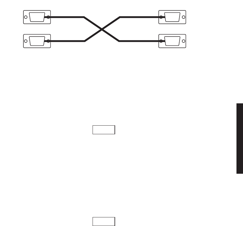
3.9.2
Wayside DS1 Repeater
Recommended connectorized cable assembly – PN 695-4125-051 (26 AWG 5 pair shielded,
jacketed cable with 9-pin D-type connector on each end). See Figure 3-9 for Wayside DS1
repeater interconnect.
Figure 3-9 Wayside DS1 Repeater Interconnect
3.10
DS3 REPEATER (J401 ON ONE SHELF TO J401 ON SECOND SHELF)
The DS3 repeater cable carries clocks, data, and overhead for two
directions. It does not carry DS3 or wayside DS1 traffic. DS3 and way-
side DS1 cables must be run separately. If the 401 cable is not used, the
embedded data in the overhead must be cabled individually. In this
case, individual cables must be run for MCS-11, audio, RS-232, and
ELMC.
Recommended connectorized cable assembly – PN 695-7836-001/005 (25 pair shielded cable
with 50 pin Amp connectors) (SCSI). See Figure 3-10 for shelf connector location and pinout.
Refer to Interconnect section on attached CD for mating cable wiring and color code.
Use repeater cables for cabling repeater shelf 1 to repeater shelf 2 (east-
bound/westbound data/clock)
SHELF 1
OUTPUT
INPUT
LMW-7071-sm
7/24/02
OUTPUT
INPUT
SHELF 2
J201
J202 J202
J201
Note
Note
3-16
Figure 3-10 Connector J401 Location – DS3 LBO
3.11
FIBER OPTIC CABLE CONNECTIONS
This system normally operates as a Class I Laser Product
(no hazard), however during servicing operations, when
optical connectors are being connected, disconnected, or
handled without dust covers, it is possible to be exposed
to Class IIIB laser radiation which can cause eye damage.
J315
J301
J313
J308 J309 J310 J312
J318 J305 J316 J317 J302
J307
25
50
PIN 1
J401
26
LMW-7066-sm
07/23/02
J301
FRONT VIEW
DANGER
Possibility of
Injury
to Personnel
3-17
Fiber optic connectors are delicate and can be damaged
easily by dirt or debris on the end of the connector. Keep
fiber optic connectors free of dust and debris by cleaning
the connector before and after use. Carefully clean the fiber
optic connector and cable ends with a cotton swab dipped
in alcohol or an alcohol wipe. Keep safety cap on connec-
tors when not in use.
The Alcatel 2 or 4 fiber management panel (PN 3EM09257AB) and 2x4 fiber management
panel (PN 3EM09257AA) connections are described. For other fiber management equip-
ment, refer to the manufacturers instructions. See Figure 3-11 and Figure 3-12 for typi-
cal connections. Refer to Table 3-5 for recommended fiber optic jumpers.
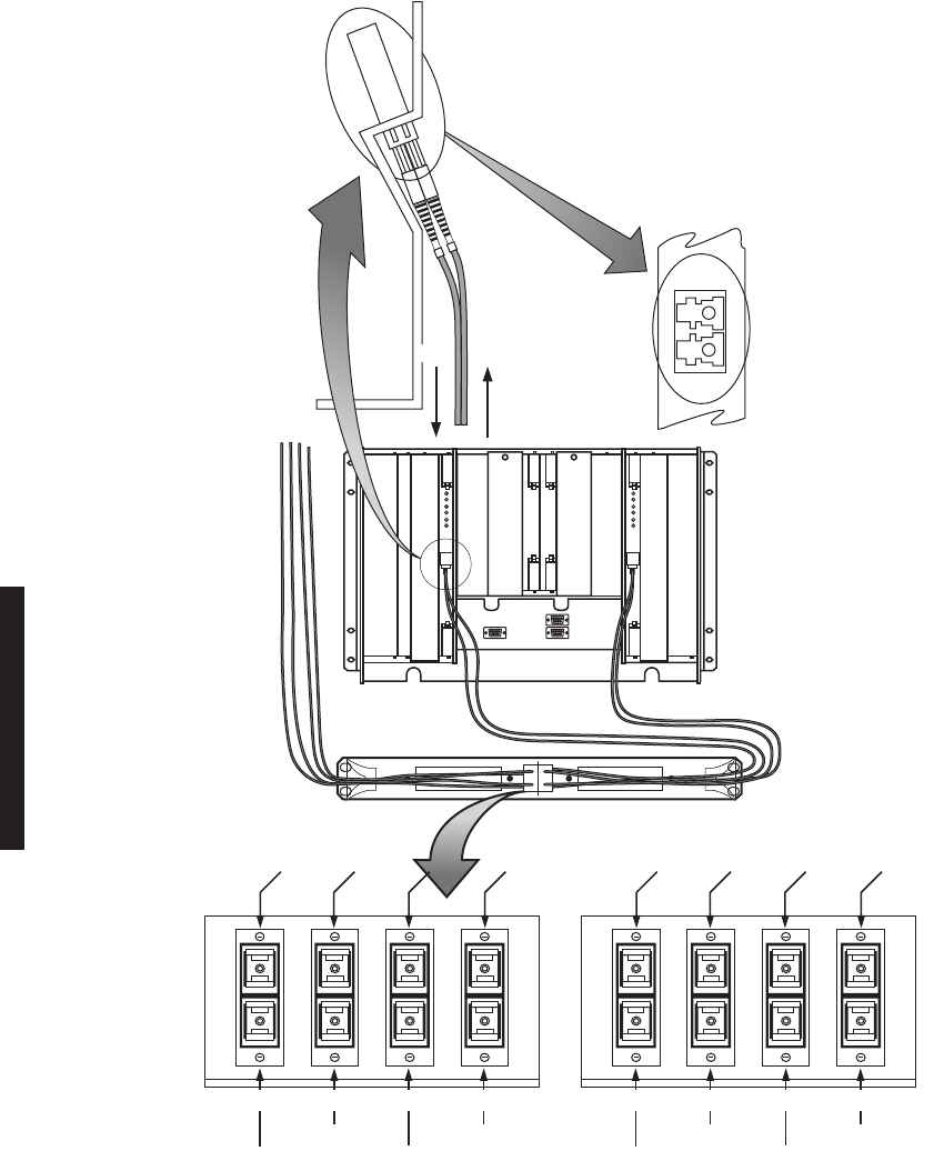
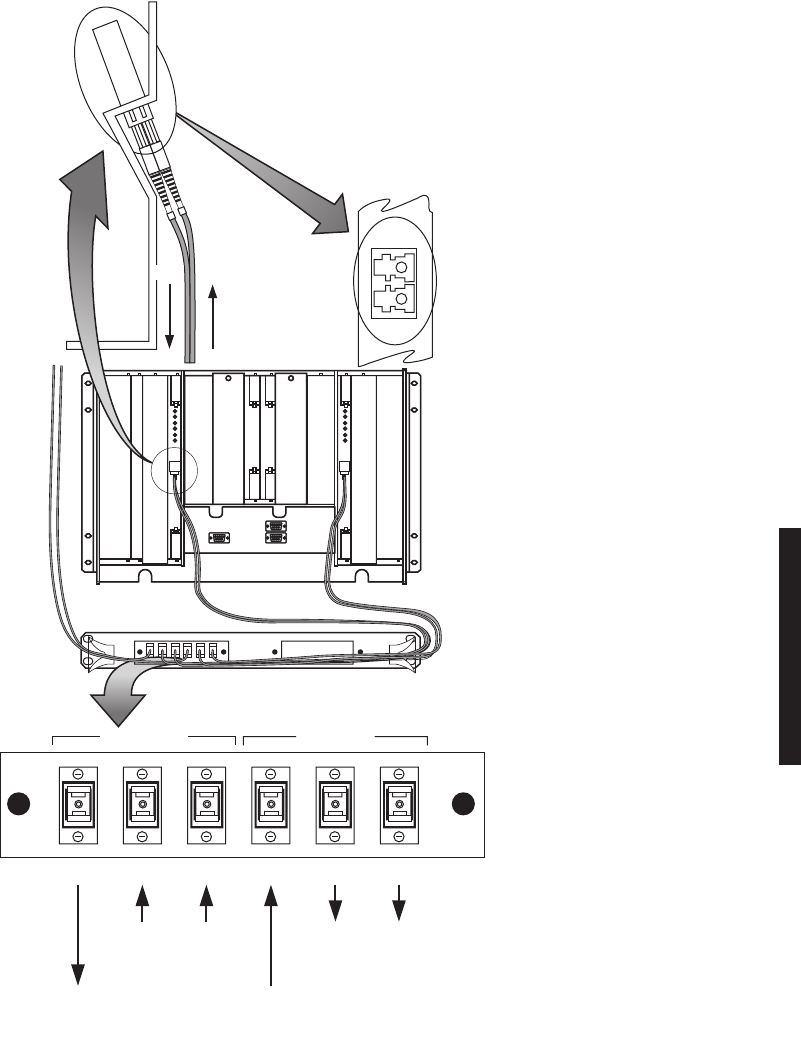
3.11.1
2 or 4 Fiber Management Panel
The 2 or 4 fiber management panel provides a direct interface with customers 2 or 4 fiber
equipment. The two fibers on a non-standby radio or four fibers on a hot-standby radio con-
nect to the two or four fibers from the customers equipment. The 2 or 4 fiber configuration
requires the duplex adapter panel to route the fiber to/from the I/O interface modules. One
duplex adapter panel can accommodate two radio shelves. Customer fiber must have SC
type connectors
3.11.2
2x4 Fiber Switched Management Panel
The 2x4 fiber management panel interfaces the four fibers on a hot-standby shelf with cus-
tomer’s 2-fiber equipment. The 2x4 fiber configuration requires combiner/splitter units to
route the fiber to/from the I/O interface modules. One combiner/splitter unit per radio shelf
is required. The 2x4-fiber management panel has cutouts for two combiner/splitter units
and can accommodate two radio shelves.
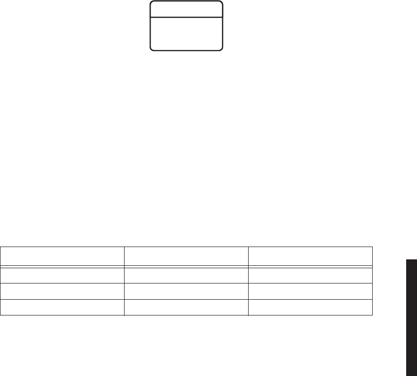
Table 3-5 Fiber Optic Jumpers
JUMPER TYPE PART NO. APPLICATION
FC to LC 3EM07651AA-AK TERMINAL
SC TO LC 3EM07646AA-AK TERMINAL
LC TO LC 3EM07641AA-AK REPEATER
WARNING
Possibility of
Damage
to Equipment
3-18
Figure 3-11 2 or 4 Fiber Management Panel
IN
OUT
SHELF 1A
SHELF 1B
SHELF 2A
SHELF 2B
OR-1
OT-1
LMW-6038
07/22/02
INPUTS
OT-3 OUT OT-1 OUT
OT-2 OUT
OR-4 IN
OR-3 IN
OUTPUTS
OR-2 IN
OR-1 IN
OR-2 IN
OR-3 IN
OR-4 IN
OT-2 OUT OT-4 OUT
OT-1 OUTOT-4 OUT OT-3 OUT
I/O INTFC MODULE SIDE VIEW
OR-1 IN
VIEW OF
CONNECTOR
WITH FIBER
OPTIC CABLES
REMOVED
CONNECT OPTICAL
RCV (OR) CABLE TO
IN CONNECTOR
CONNECT OPTICAL
XMT (OT) CABLE TO
OUT CONNECTOR
CUSTOMER INTFC SIDE VIEW
3-19
Figure 3-12 2x4 Fiber Management Panel
COM
COM A
A
BAB
OT-1 OT-2
OUTPUT TO
CUSTOMER
2 FIBER
INPUT FROM
CUSTOMER
2 FIBER
COMBINER
FRONT VIEW
TO RADIO I/O
INTFC MODULES
FROM RADIO I/O
INTFC MODULES
COM
COM
OR-1
OR-1 OR-2
SPLITTER
IN
OUT
VIEW OF
CONNECTOR
WITH FIBER
OPTIC CABLES
REMOVED
LMW-6037-sm
07/22/02
CONNECT OPTICAL RCV
(OR) CABLE TO IN CONNECTOR
CONNECT OPTICAL XMT
(OT) CABLE TO OUT CONNECTOR
OT-1
B
A
B
3-20
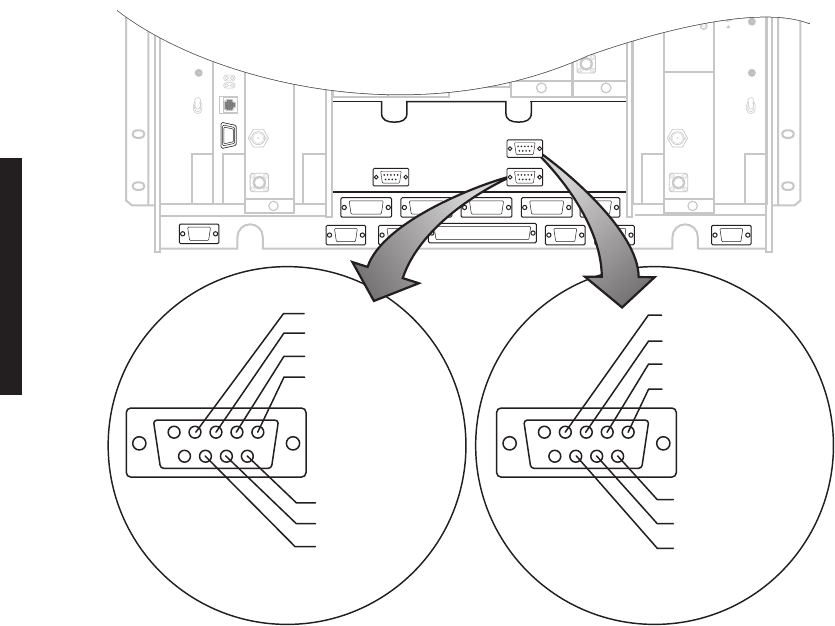
3.12
OC3 AUX INTERFACE BOARD WAYSIDE DS1 CONNECTIONS (J201 IN AND J202 OUT)
Wayside DS1 is an option in the MDR-8000 OC3 radios that prevents having to add a
SONET add/drop MUX to access payload traffic. This option provides 1 DS1 for each STS-1
within the OC3. Refer to Table 3-4 for ELMC option key requirements for remote monitor-
ing/controlling wayside DS1.
3.12.1
Wayside DS1 Terminal
Recommended connectorized cable assembly – PN 695-4125-041 (26 AWG 5 pair shielded,
jacketed cable with 9-pin D-type connector on one end). See Figure 3-13 for location. Refer
to Interconnect section on attached CD for pinout and color code.
3.12.2
Wayside DS1 Repeater
Recommended connectorized cable assembly – PN 695-4125-051 (26 AWG 5 pair shielded,
jacketed cable with 9-pin D-type connector on each end). See Figure 3-9 for Wayside DS1
repeater interconnect.
Figure 3-13 Wayside DS1 Connectors – OC3 AUX Interface
J315
J301
J313
J308 J309 J310 J312
J318 J305 J316 J317 J302
J307
J201
INPUT
FRONT VIEW
51
96
GND
LINE 3 IN TIP
LINE 2 IN TIP
LINE 1 IN TIP
LINE 1 IN RING
LINE 2 IN RING
LINE 3 IN RING
51
96
LINE 3 OUT TIP
J202
OUTPUT
FRONT VIEW
GND
LINE 1 OUT TIP
LINE 2 OUT TIP
LINE 1 OUT RING
LINE 2 OUT RING
LINE 3 OUT RING
LMW-7068-sm
07/23/02
J301
3-21
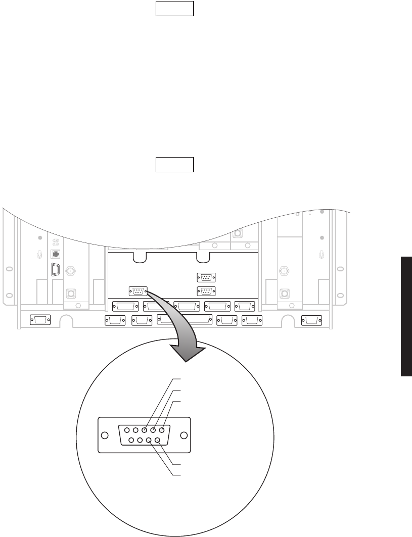
3.13
OC3 REPEATER (J203 ON ONE SHELF TO J203 ON SECOND SHELF)
The OC3 radio repeater cable carries clocks, data, and overhead for two
directions. It does not carry OC3 or Wayside DS1 traffic. OC3 fiber
optic cables and Wayside DS1 cables must be run separately. If the
repeater cable is not used, the embedded data in the overhead must be
cabled individually. In this case, separate cables must be run for MCS-
11, audio, RS-232, and ELMC.
Recommended connectorized cable assembly – PN 695-4125-007/013 (26 AWG 5 pair
shielded, jacketed cable). See Figure 3-14 for shelf connector location and pinout. Refer to
Interconnect section on attached CD for mating cable wiring and color code.
Use repeater cables for cabling repeater shelf 1 to repeater shelf 2 (east-
bound/westbound data/clock)
Figure 3-14 Repeater Connector – OC3 AUX Interface
Note
Note
J315
J301
J313
J308 J309 J310 J312
J318 J305 J316 J317 J302
J307
J203
FRONT VIEW
51
96
GND
RPTR DS1 OUT TIP
RPTR DS1 IN TIP
RPTR DS1 OUT RING
RPTR DS1 IN RING
LMW-7067
07/23/02
J301
3-22
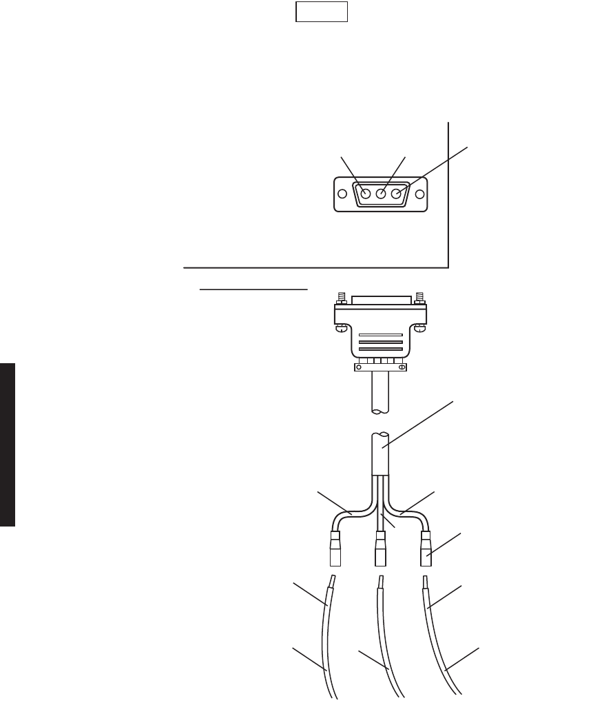
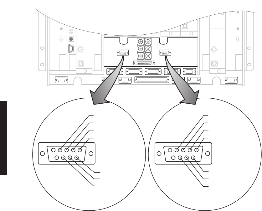
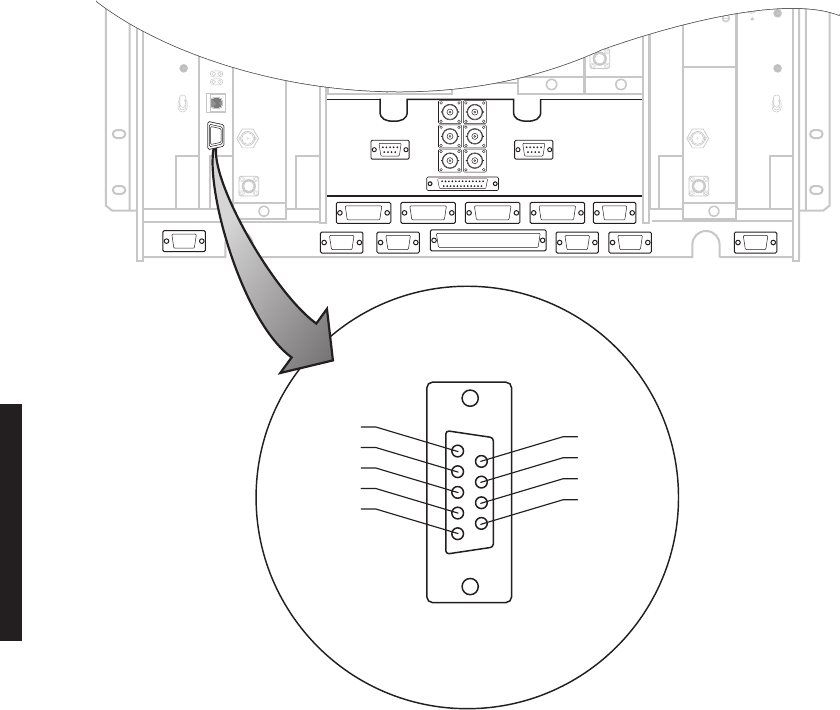
3.14
USI/CONTROLLER CABLE CONNECTION TO LAPTOP (J301)
Recommended connectorized cable assembly – PN 695-7848-001 through 004 (24 AWG 6
pair shielded, jacketed cable with DEMM-9P connector on each end). See Figure 3-15 for
controller connector location and pinout. Refer to attached CD for mating cable pinout and
color code.
Figure 3-15 Controller USI Connector Location and Pinout
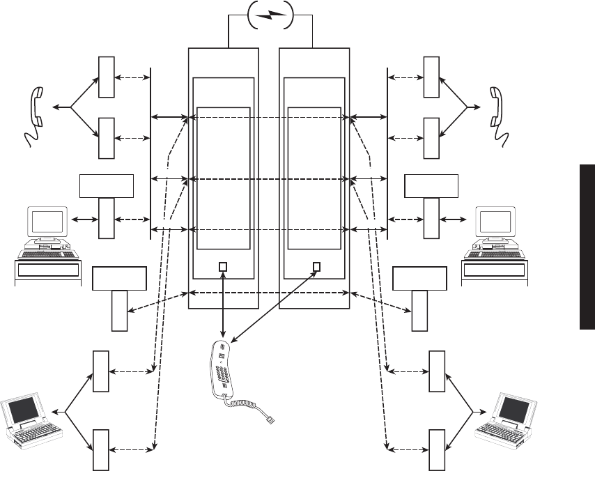
3.15
SERVICE CHANNEL
A service channel is defined as a non-revenue bearing channel provided as part of a trans-
mission system for operation, maintenance, monitoring, and control of the system. The
MDR-8000 provides a 256 kb/s auxiliary channel for servicing the radio. This is an over-
head channel and is independent of the traffic channels. The 256 kb/s service channel con-
tains four 64 kb/s service channels. Three of the four 64 kb/s channels (Service Channel 1,
2, and 3) can be provisioned on the USI for a specific use. Service channel 0 is dedicated to
radio commands and ELMC. Service channel 0 is not provisionable. The four channels are
multiplexed and shifted in and out of registers on the controller.
J315
J301
J313
J308 J309 J310 J312
J318 J305 J316 J317 J302
J307
J301
FRONT VIEW
USI
51
96
DTR
GND
TxD
RxD
DCD
RTS
DSR
CTS
RI
LMW-7059
02/04/03
J301
3-23
See Figure 3-16. There are eight connectors on the backplane to interface with three of the
service channels. The connectors on the backplane interface three functions: audio, RS-
232, and MCS-11. Each service channel is provisioned for a specific function. As shown by
the vertical line connecting to the three functions on one side and the three service chan-
nels (SC1, SC2, and SC3) on the opposite side, audio and MCS can be put on any open ser-
vice channel. RS-232 data can be put on service channel 1 or 2 but cannot be put on service
channel 3. This is shown by the dashed lines to the specific service channel.
3.15.1
Handset Jack
The 2-wire port at the TEL connector on AE-37Y Controller accepts either the optional
handset or a standard telephone. The 2-wire port is not provisionable. To use the handset,
the radio must be provisioned for Audio 1.
Figure 3-16 Service Channel Connections/Applications
J316
J317
J307, J310
(BRIDGED)
J307, J310
(BRIDGED)
OVERHEAD
CHANNELS
OVERHEAD
CHANNELS
TSM–2500 TSM–2500
SC1
AUDIO
1
AUDIO
2
MCS
J315, J318
(BRIDGED)
ELMC
J315, J318
(BRIDGED)
ELMC
SC0 SC0
TELEPHONE
(4-WIRE)
HANDSET
(2-WIRE)
J312
J313
RS232–1
RS232–2
LAPTOP
SC2
SC3
J316
J317
SC1
AUDIO
1
AUDIO
2
MCS
TELEPHONE
(4-WIRE)
J312
J313
RS232–1
RS232–2
LAPTOP
SC2
SC3
RADIO
CONTROLLER
SC
MULDEM
RADIO
CONTROLLER
SC
MULDEM
TEL TEL
LMW-3138
04/21/04

3-24
3.15.2
Service Channels Provisioning Options
Service channels at both ends of a hop (and end-to-end in a link) must
be provisioned the same.
Service channel provisioning is interactive. When an option is selected for any service
channel, that option is excluded from selections on the other applicable service channels.
Provisioning options for Service Channels 1, 2, and 3 are listed:
•Service Channel 1 (64 kb/s channel) – can be used to carry 4-wire audio, RS-232 data,
or MCS-11 fault alarm information.
•AUDIO 1 and 2 – Two audio provisioning options (AUDIO 1 and AUDIO 2) are pro-
vided for Service Channel 1. Each audio channel is a 4-wire audio channel that pro-
vides off-hook detection, level control, and E and M-lead signaling. AUDIO 1 also
has DTMF decoding that allows a specific station to be dialed. External connection
to AUDIO 1 is J316. External connection to AUDIO 2 is J317.
•RS-232-1 – RS-232 Channel 1 is an RS-232 formatted data channel that can pro-
vide interface to an external computer/modem. External connection to RS-232-1 is
J312.
•MCS-11 – The MCS-11 channel is an RS-422 formatted data that provides an
interface to an external MCS-11 Monitor and Control System or TSM system (used
to control multiple MCS-11 systems). External connections to the MCS-11 include
J307, J308, J309 and J310.
•Service channel 2 (64 kb/s channel) – can be used to carry 4-wire audio, RS-232 data, or
MCS-11 fault alarm information.
•AUDIO-1 and -2 – Same as Service Channel 1
•RS-232-2 – RS-232 Channel 2 is an RS-232 formatted data channel that can pro-
vide interface to an external computer/modem. External connection to RS-232-2 is
J313.
•MCS-11 – Same as Service Channel 1
•Service Channel 3 (64 kb/s channel) – can be used to carry 4-wire audio, or MCS-11
fault alarm information
•AUDIO 1 and 2 – Same as Service Channel 1
•MCS-11 – Same as Service Channel 1.
3.15.3
Audio 1, Audio 2 (J316, J317)
The Audio 1 and 2 4-wire functions are provisionable. Refer to the Initial Turnup section
for details. These audio functions should not be confused with the non-provisionable 2-wire
handset.
Note
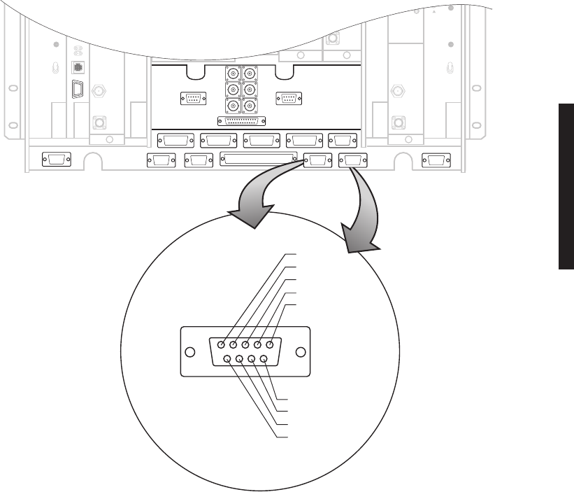
3-25
Audio 1
Audio 1 (J316) is a 4-wire function port on the backplane that provides off-hook detection,
level control, E and M-lead signaling, DTMF, and 2-wire handset capabilities.
Audio 2
Audio 2 (J317) is a 4-wire function port on the backplane that provides off-hook detection,
level control, and E and M-lead signaling. Audio 2 has no DTMF decoding capabilities.
Recommended connectorized cable assembly – PN 695-4125-026 through 030 (26 AWG 5 pair
shielded, jacketed cable with 9-pin D-type connector on each end). See Figure 3-17 for shelf
connector locations and pinout. Refer to Table 3-6 for mating cable wiring and color code.
or
Recommended cable – PN 424-0305-030 (26 AWG 5 pair shielded, jacketed cable) for wire-
wrapping to wirewrap adapter PN 3DH04178AB. See Figure 3-18 for pinout. Refer to
Table 3-6 for mating cable wiring and color code.
Figure 3-17 Audio Connectors Location and Pinout
J315
J301
J313
J308 J309
J310
J312
J318 J305
J316 J317
J302
51
96
CALL DETECT
J316/J317
FRONT VIEW
GND
AUDIO TIP OUT
M LEAD
AUDIO TIP IN
E LEAD
AUDIO RING IN
AUDIO RING OUT
CALL COMMON
J307 J312J308 J309
J316 J317
LMW-7238
02/23/04
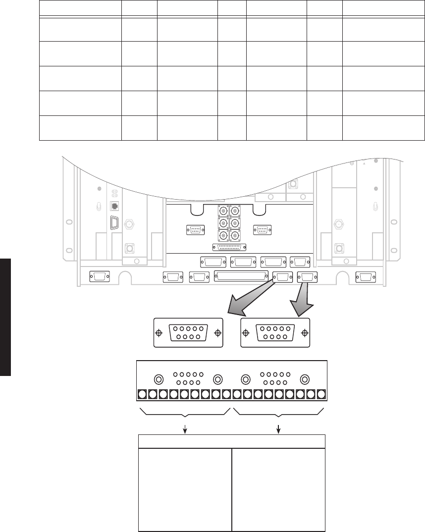
3-26
Figure 3-18 Audio Wirewrap Adapter Pinout
Table 3-6 Audio Mating Cable Wiring and Color Codes
FUNCTION END 1 WIRE COLOR PAIR WIRE COLOR END 2 FUNCTION
AUDIO TIP IN 01 BLACK 1 BLACK 03 AUDIO TIP OUT
AUDIO RING IN 06 RED 1 RED 08 AUDIO RING OUT
AUDIO M LEAD 02 BLACK 2 BLACK 07 AUDIO E LEAD
AUDIO E LEAD 07 WHITE 2 WHITE 02 AUDIO M LEAD
AUDIO TIP OUT 03 BLACK 3 BLACK 01 AUDIO TIP IN
AUDIO RING OUT 08 GREEN 3 GREEN 06 AUDIO RING IN
CALL DETECT 04 BLACK 4 BLACK 04 NOT USED
CALL COMMON 09 BLUE 4 BLUE 09 NOT USED
GND 05 BLACK 5 BLACK 05 GND
NOT USED 10 YELLOW 5 YELLOW 10 NOT USED
J315
J301
J313
J308 J309 J310 J312
J318 J305 J316 J317 J302
51
96
J316
P101
P101P316
1 AUDIO TIP IN A1
6 AUDIO RING IN A2
2 AUDIO M LEAD A3
3 AUDIO TIP OUT A4
8 AUDIO RING OUT A5
7 AUDIO E LEAD A6
4 CALL DETECT A7
9 CALL COMMON A8
5 GND A9
P102P317
1 AUDIO TIP IN A1
6 AUDIO RING IN A2
2 AUDIO M LEAD A3
3 AUDIO TIP OUT A4
8 AUDIO RING OUT A5
7 AUDIO E LEAD A6
4 CALL DETECT A7
9 CALL COMMON A8
5 GND A9
P102
51
96
J317
P316 P317
WIRE WRAP ADAPTER
PN 3DH04178 AB
WIRE WRAP ADAPTER PINS
1919
J316 J317
LMW-7055
09/06/03
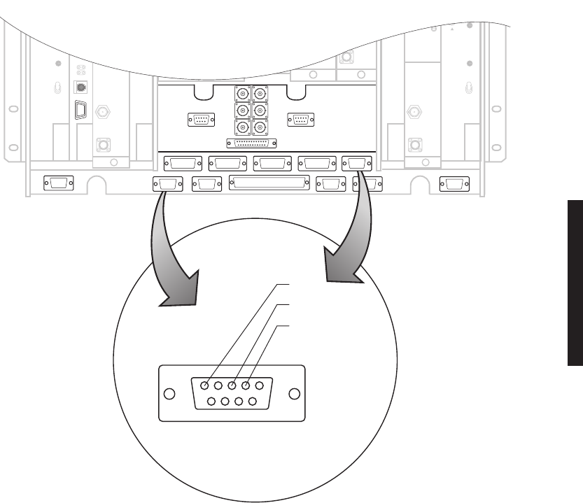
3-27
3.15.4
RS-232-1, RS-232-2 (J312, J313)
Recommended connectorized cable assembly – PN 695-4125-021 through 025 (26 AWG 5 pair
shielded, jacketed cable with 9-pin D-type connector on each end). See Figure 3-19 for shelf
connector locations and pinout. Refer to Table 3-7 for mating cable wiring and color code.
Figure 3-19 RS-232 Connectors Location and Pinout
J315
J301
J313
J308 J309 J310 J312
J318 J305 J316 J317 J302
J312/J313
FRONT VIEW
51
96
GND
RS-232 IN
RS-232 OUT
J307 J312
LMW-7056
07/23/02
J308 J309
J313

3-28
3.15.5
MCS-11 Connections
When MCS is selected to be placed on one of the three service channels and then RSS is
enabled and properly addressed, applicable ports on the controller module are enabled.
This allows the user to interface external MCS-11 Monitor and Control System equipment
at any or all four connectors on the backplane (J307, J308, J309, and J310). Two connec-
tors (J308 and J309) are synchronous, parallel, data ports and provide CLK outputs. Con-
nectors J307 and J310 are asynchronous ports.
For proper operation, MCS-11 must be provisioned using the following guidelines:
a.
MCS-11
must be selected as one of the service channels.
b. MCS must be assigned a valid address
c. The
MCS RSS
must be set to
ON
for each radio with a unique RSS address. Refer to
Appendix B on the attached CD for address details. At a site, typically only one RSS is
turned on. Station scanners at all other radios at that site are normally jumpered to the
RSS enabled radio to allow access to their detail scanners. If station scanners are prop-
erly wired, detail scanners always respond, regardless of whether RSS is provisioned
ON
or
OFF
.
Table 3-7 RS-232 Mating Cable Wiring and Color Codes
J312/J313 MDR-8000 J312/J313 J312/J313 MDR-8000
FUNCTION END 1 WIRE COLOR PAIR WIRE COLOR END 2 FUNCTION
NOT USED 01 BLACK 1 BLACK 01 NOT USED
NOT USED 06 RED 1 RED 06 NOT USED
RS-232 OUT/
RS-232-1 OUT*
02 BLACK 2 BLACK 03 RS-232 IN/
RS-232-1 IN*
NOT USED 07 WHITE 2 WHITE 08 NOT USED
RS-232 IN/
RS-232-1 IN* 03 BLACK 3 BLACK 02 RS-232 OUT/
RS-232-1 OUT*
NOT USED 08 GREEN 3 GREEN 07 NOT USED
NOT USED/
RS-232-2 OUT*
04 BLACK 4 BLACK 04 NOT USED
/
RS-232-2 OUT*
NOT USED/
RS-232-2 IN* 09 BLUE 4 BLUE 09 NOT USED/
RS-232-2 IN*
GND 05 BLACK 5 BLACK 05 GND
NOT USED 10 YELLOW 5 YELLOW 10 NOT USED
*J312 on CommPak Radio

3-29
MCS-11 must be provisioned
MCS-11 J310 Master/Junction
to enable
XMT, RCV, and OUTPUT clocks. If an external modem is being used,
provision MCS-11 for
MCS-11 J310 Modem
. This selection disables
XMT, RCV, and OUTPUT clocks and all MCS-11 clocks must now be
provided by the external modem.
d.
MCS-11 J310 Master/Junction
must be selected unless an external modem is con-
nected to the radio. If an external modem is used it must provide all MCS-11 clocks and
the radio must be provisioned
MCS-11 J310 Modem
.
When provisioned
J308 Input Clock
, J308 and J309 RCV CLK and
XMT CLK and J308 OUTPUT CLK are disabled. Select
J308 Output
Clock
to send a 64 kb/s clock to external equipment (OUTPUT CLK
J308-4/12) and also enable RCV CLK and XMT CLK.
e.
MCS-11 J308 Output Clock
must be selected unless an external clock source is pro-
vided that will supply all MCS-11 clocks. If an external clock source is used, the radio
must be provisioned
MCS-11 J308 Input Clock
.
3.15.5.1
MCS-11 (J307)
If the radio is provisioned
Repeater
, port 2 on the controller, that con-
nects to J307, is disabled. At a repeater, you can use J310 in lieu of
J307 for connecting the TSM polling engine to the radio.
MCS-11 connector J307 is used to connect to a TSM (-2500, -3500, or -8000) polling engine
at a master terminal.
Recommended connectorized cable assembly – PN 695-4126-007/009/012 (26 AWG 8 pair
shielded, jacketed cable). See Figure 3-20 for shelf connector location and pinout. Refer to
Table 3-8 for mating cable pinout and color code. See Figure 3-21 for typical connection
scheme.
Note
Note
Note
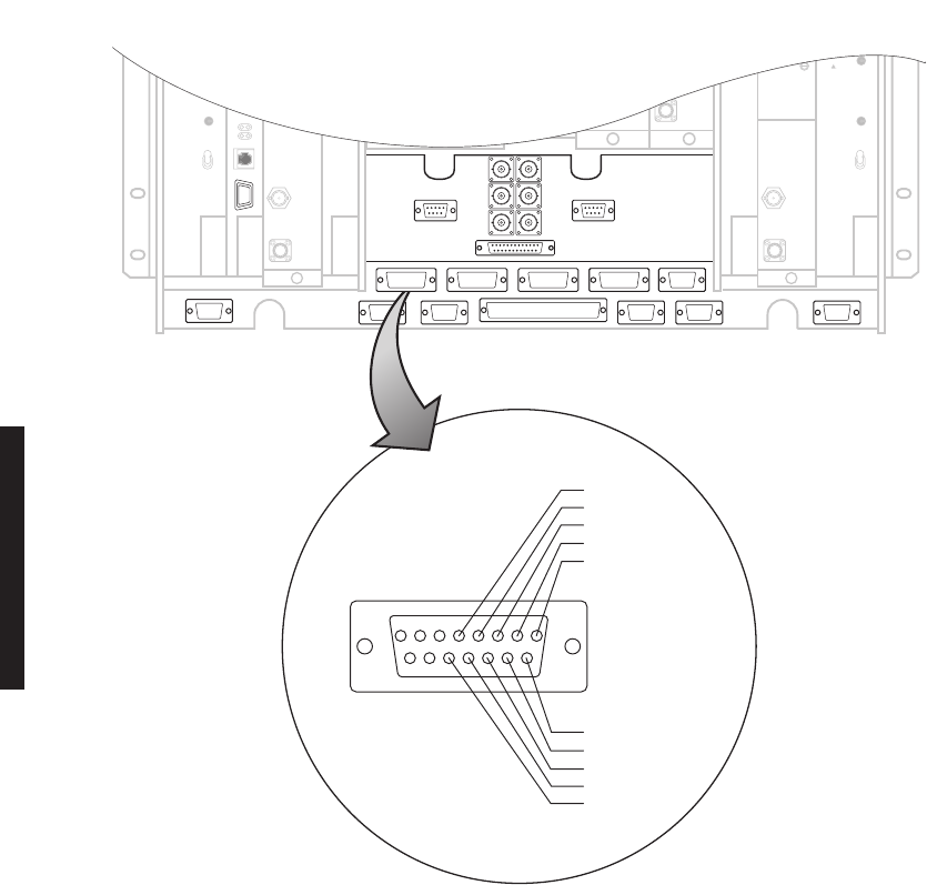
3-30
Figure 3-20 MCS-11 Master Connector Location and Pinout
J315
J301
J313
J308 J309 J310 J312
J318 J305 J316 J317 J302
XMT DATA +
J307
FRONT VIEW
RTN CLK +
XMT CLK +
RCV DATA +
RCV CLK +
RCV CLK –
RCV DATA –
XMT CLK –
RTN CLK –
XMT DATA –
81
15 9
J307 J312
LMW-7052
07/23/02
J310

3-31
Table 3-8 MCS-11 Master Connector J307 Mating Cable Wiring and Color Codes
J307 MDR-8000 POLLING ENGINE
FUNCTION END 1 WIRE COLOR PAIR WIRE COLOR END 2 FUNCTION
RCV CLK + 01 BLACK 1 BLACK 01 RCV CLK +
RCV CLK- 09 RED 1 RED 09 RCV CLK-
RCV DATA + 02 BLACK 2 BLACK 02 RCV DATA +
RCV DATA - 10 WHITE 2 WHITE 10 RCV DATA -
XMT CLK + 03 BLACK 3 BLACK 03 XMT CLK +
XMT CLK - 11 GREEN 3 GREEN 11 XMT CLK -
RETURN CLK + 04 BLACK 4 BLACK 04 RETURN CLK +
RETURN CLK - 12 BLUE 4 BLUE 12 RETURN CLK -
XMT DATA + 05 BLACK 5 BLACK 05 XMT DATA +
XMT DATA - 13 YELLOW 5 YELLOW 13 XMT DATA -
NOT USED 06 BLACK 6 BLACK 06 OFF HOOK +
NOT USED 14 BROWN 6 BROWN 14 OFF HOOK -
NOT USED 07 BLACK 7 BLACK 07 RCV DATA
NOT USED 15 ORANGE 7 ORANGE 15 SIG GND
NOT USED 08 RED 8 RED 08 DTR
NOT USED 16 WHITE 8 WHITE 16 NOT USED
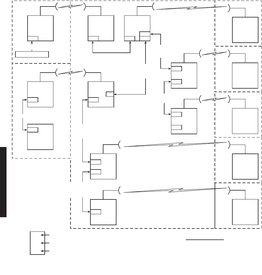
3-32
Figure 3-21 Typical MCS-11 System
B1
TERM.
DS307
MDR-8000 MDR-8000
B2
RPTR
DS308
A10
B3
RPTR
DS309
REPEATER CABLE
695-7836-001 THRU -005
695-7837-001
THRU -005
CROSSWIRE
695-7801-001
STRAIGHT
CABLE
695-7837-025
STRAIGHT
CABLE
695-7837-025
RPTR
CABLE
372-0546-020/050/070
J309
MDR-4000e
MUX
TERM
A9
MDR-4000e
J311
J306
TERM
MDR-1023
06/08/04
J308
J307 J401 J401 J310
B5
TERM
DS303
MDR-8000
J308
J309
B7
TERM
DS301
MDR-8000
J308
J309
MDR-8000
B4
TERM 4
DS310
MDR-8000
DMX-3003N
J202
J310
J314
E1A
MDR-6000
RPTR
G7572
E2A
MDR-6000
TERM
P7572
E4A
MDR-6000
TERM
T7341
E3A
MDR-6000
RPTR
S7341
J314
MDR-8000
B6
TERM
DS304
MDR-8000
B8
TERM
DS302
LEGEND:
XXXX
YYYY
ZZZZ
MCS-11 ADDRESS
CONFIGURATION
ELMC ADDRESS
DS3ZZ = RADIO CAPACITY (DS3)
AND SHELF NUMBER (DS301 - SHELF 1)
MDR-8000 J308/J309
PROVISIONING NOTES
1. PROVISION RPTR DS309 (FIRST
RADIO IN CHAIN) J308 OUTPUT CLOCK.
2. PROVISION ALL OTHER RADIOS IN
DAISY CHAIN (TERM DS303 AND TERM
DS301) J308 INPUT CLOCK.
695-4126-007/009/012
695-7837-021
THRU -025
POLLING ENGINE
SITE C SITE D
SITE E
SITE F
SITE G
SITE H
SITE B
SITE A

3-33
3.15.5.2
MCS-11 Repeater-to-Spur Daisy Chain Connection (J308/J309)
MCS-11 must be provisioned
MCS-11 J310 Master/Junction
to enable
XMT, RCV, and OUTPUT clocks. If an external modem is being used,
provision MCS-11 for
MCS-11 J310 Modem
. This selection disables
XMT, RCV,OUTPUT clocks and all MCS-11 clocks must now be pro-
vided by the external modem.
Multiple radios at a site can be provisioned and connected to operate
using a common XMT and RCV clock. In this scenario, one radio is
provisioned to supply the clocks. All other radios are provisioned to
sync off the supplied clocks. Provision the radio supplying the clocks
J308 Output Clock
. Provision all other radios at the site
J308 Input
Clock
.
MCS-11 connector J308/J309 is typically used to connect a repeater to a spur or multiple
spurs in a daisy chain system configuration. Either repeater shelf 1 or repeater shelf 2 may
feed the spur shelf. The first connection out of the repeater must be crosswired from J308
to J308. Then, every shelf from the spur must be wired 1:1, J309 to J308, in a daisy-chain
fashion.
CROSSWIRED CABLE ASSEMBLY – Recommended connectorized cable assembly – PN
695-7837-001 through -005 (26 AWG 8 pair shielded, jacketed cable with 15-pin D-type
connector on each end). See Figure 3-22 for shelf connector J308 location and pinout. See
Figure 3-22 for shelf connector J309 location and pinout. Refer to Table 3-9 for J308 to
J308 mating cable pinout and color code. See Figure 3-21 for typical connection scheme.
DAISY CHAIN CABLE ASSEMBLY – Recommended connectorized cable assembly – PN
695-7837-021 through -025 (26 AWG 8 pair shielded, jacketed cable with 15-pin D-type
connector on each end, wired 1:1.) Refer to Table 3-10 for J309 to J308 mating cable pinout
and color code. See Figure 3-21 for typical connection scheme.
Note
Note
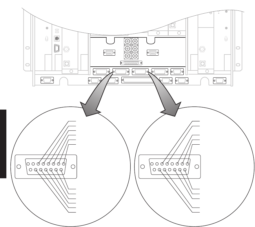
3-34
Figure 3-22 MCS-11 Connector J308 and J309 Location and Pinout
J315
J301
J313
J308 J310 J312
J318 J305 J316 J317 J302
XMT DATA +
J308
FRONT VIEW
CLK OUT +
OFF HOOK +
XMT CLK +
RCV DATA +
RCV CLK +
RCV CLK –
RCV DATA –
XMT CLK –
CLK OUT –
XMT DATA –
OFF HOOK –
81
15 9
XMT DATA +
J309
FRONT VIEW
OFF HOOK +
XMT CLK +
RCV DATA +
RCV CLK +
RCV CLK –
RCV DATA –
XMT CLK –
XMT DATA –
OFF HOOK –
81
15 9
J307 J312
MDR-1012
04/12/04
J309J308

3-35
Table 3-9 J308-to-J308 Mating Cable Wiring and Pinout
J308 MDR-8000 J308/J308 J308 MDR-8000
FUNCTION END 1 WIRE COLOR PAIR WIRE COLOR END 2 FUNCTION
RCV CLK + 01 BLACK 1 BLACK 03 XMT CLK +
RCV CLK- 09 RED RED 11 XMT CLK-
RCV DATA + 02 BLACK 2 BLACK 05 XMT DATA +
RCV DATA - 10 WHITE WHITE 13 XMT DATA -
XMT CLK + 03 BLACK 3 BLACK 01 RCV CLK +
XMT CLK - 11 GREEN GREEN 09 RCV CLK -
CLK OUT+ 04 BLACK 4 BLACK 04 NOT USED
CLK OUT - 12 BLUE BLUE 12 NOT USED
XMT DATA + 05 BLACK 5 BLACK 02 RCV DATA +
XMT DATA - 13 YELLOW YELLOW 10 RCV DATA -
OFF HOOK + 06 BLACK 6 BLACK 06 OFF HOOK +
OFF HOOK - 14 BROWN BROWN 14 OFF HOOK -
NOT USED 07 BLACK 7 BLACK 07 NOT USED
NOT USED 15 ORANGE ORANGE 15 NOT USED
NOT USED 08 RED 8 RED 08 NOT USED
NOT USED WHITE WHITE NOT USED
Table 3-10 J309-to-J308 Mating Cable Wiring and Pinout
309 MDR-8000 J309/J308 J308 MDR-8000
FUNCTION END 1 WIRE COLOR PAIR WIRE COLOR END 2 FUNCTION
RCV CLK + 01 BLACK 1 BLACK 01 RCV CLK +
RCV CLK- 09 RED RED 09 RCV CLK-
RCV DATA + 02 BLACK 2 BLACK 02 RCV DATA +
RCV DATA - 10 WHITE WHITE 10 RCV DATA -
XMT CLK + 03 BLACK 3 BLACK 03 XMT CLK +
XMT CLK - 11 GREEN GREEN 11 XMT CLK -
CLK OUT+ 04 BLACK 4 BLACK 04 NOT USED
CLK OUT - 12 BLUE BLUE 12 NOT USED
XMT DATA + 05 BLACK 5 BLACK 05 XMT DATA +
XMT DATA - 13 YELLOW YELLOW 13 XMT DATA -
OFF HOOK + 06 BLACK 6 BLACK 06 OFF HOOK +
OFF HOOK - 14 BROWN BROWN 14 OFF HOOK -
NOT USED 07 BLACK 7 BLACK 07 NOT USED
NOT USED 08 ORANGE ORANGE 15 NOT USED
NOT USED 15 RED 8 RED 08 NOT USED
NOT USED 16 WHITE WHITE 16 NOT USED
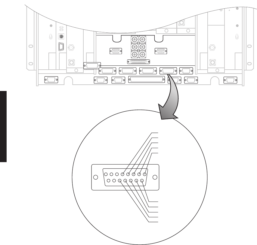
3-36
3.15.5.3 MCS-11 Spur Connection (J310)
MCS-11 connector J310 can be used to connect to a spur shelf and is the preferred connec-
tion to the external DMX-3003N MUX. When connecting to a MDR-4000e or MDR-6000
radio use J310 on all of the radios for best results.
Recommended connectorized cable assembly – PN 695-4126-031 through -035 (26 AWG 8
pair shielded, jacketed cable with 15-pin D-type connector on each end). See Figure 3-23
for shelf connector J310 location and pinout. Refer to Table 3-11 for mating cable wiring
and color code. See Figure 3-21 for typical connection scheme.
Figure 3-23 MCS-11 Spur Connector J310 Location and Pinout
J315
J301
J313
J307
J308 J309 J310 J312
J318 J305 J316 J317 J302
XMT DATA +
J310
FRONT VIEW
RTN CLK +
XMT CLK +
RCV DATA +
RCV CLK +
RCV CLK –
RCV DATA –
XMT CLK –
RTN CLK –
XMT DATA –
81
15 9
J307 J312
LMW-7072
07/23/02
J310

3-37
3.15.6 ELMC (J315, J318)
As a standard feature, the Extended Link Monitor Channel (ELMC) function allows local
provisioning, alarms, status information, and control commands for the local radio and,
(with the exception of wayside DS1), alarms, status information, control for addressable
remote radios. For wayside DS1 status, the ELMC option key (695-5647-019 or -020) must
be installed on the AE-37Y Controller. For remote provisioning and downloading capabil-
ity, the ELMC option key (695-5647-018 or 695-5647-020) must be installed on the AE-37Y
Controller. Refer Table 3-12 for details.
Recommended connectorized cable assembly – PN 695-4125-006/013 (26 AWG 5 pair
shielded, jacketed cable). See Figure 3-24 for shelf connectors locations and pinout. Refer
to Table 3-13 for mating cable wiring and color code. See Figure 3-25 for typical connec-
tion scheme.
Table 3-11 MCS-11 Spur Connector J310 Mating Cable Wiring and Pinout
J310 MDR-8000 J310/J310 J310 MDR-8000
FUNCTION END 1 WIRE COLOR PAIR WIRE COLOR END 2 FUNCTION
RCV CLK + 01 BLACK 1 BLACK 04 RETURN CLK +
RCV CLK- 09 RED 1 RED 12 RETURN CLK-
RCV DATA + 02 BLACK 2 BLACK 05 XMT DATA +
RCV DATA - 10 WHITE 2 WHITE 13 XMT DATA -
XMT CLK + 03 BLACK 3 BLACK 03 XMT CLK +
XMT CLK - 11 GREEN 3 GREEN 11 XMT CLK -
RETURN CLK + 04 BLACK 4 BLACK 01 RCV CLK +
RETURN CLK - 12 BLUE 4 BLUE 09 RCV CLK -
XMT DATA + 05 BLACK 5 BLACK 02 RCV DATA +
XMT DATA - 13 YELLOW 5 YELLOW 10 RCV DATA -
NOT USED 06 BLACK 6 BLACK 06 NOT USED
NOT USED 14 BROWN 6 BROWN 14 NOT USED
NOT USED 07 BLACK 7 BLACK 07 NOT USED
NOT USED 15 ORANGE 7 ORANGE 15 NOT USED
NOT USED 08 RED 8 RED 08 NOT USED
NOT USED 16 WHITE 8 WHITE 16 NOT USED

3-38
ELMC 1 connector J318 and ELMC 2 connector J315 are wired in par-
allel. You can connect J315 to J315, J315 to J318, or J318 to J318. A
typical connection scheme is shown.
Table 3-12 ELMC Option Keys
ELMC Option Key 695-5647-018 Required for remote provisioning and downloading
on DS1/E1 radios, and DS3 and OC3 radios with-
out wayside DS1
ELMC Option Key 695-5647-019 Required for status of DS3 and OC3 radios with
wayside DS1 (no remote provisioning or download
capability provided)
ELMC Option Key 695-5647-020 Required for remote provisioning and downloading
of DS3 and OC3 radios with wayside DS1
Table 3-13 ELMC Connector J315/J318 Mating Cable Wiring and Pinout
J315/J318 MDR-8000 J315/J318 MDR-8000
FUNCTION END 1 WIRE COLOR PAIR WIRE COLOR END 2 FUNCTION
RCV+ 01 BLACK 1 BLACK 02 XMT+
RCV- 06 RED RED 07 XMT-
XMT+ 02 BLACK 2 BLACK 01 RCV+
XMT- 07 WHITE WHITE 06 RCV-
NOT USED BLACK 3 BLACK NOT USED
GND 03 GREEN GREEN 03 GND
NOT USED 04 BLACK 4 BLACK 05 NOT USED
NOT USED 08 BLUE BLUE 09 NOT USED
NOT USED 05 BLACK 5 BLACK 04 NOT USED
NOT USED 09 YELLOW YELLOW 08 NOT USED
Note
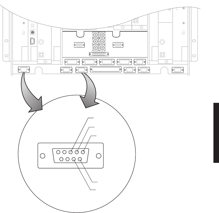
3-39
Figure 3-24 ELMC Connectors Location and Pinout
J315
J301
J313
J308 J309 J310 J312
J318 J305 J316 J317 J302
5
9876
4321
J315/J318
FRONT VIEW
GND
XMT +
RCV +
XMT –
RCV –
J307 J312J308 J309
J313
J315 J318
LMW-7237
02/23/04
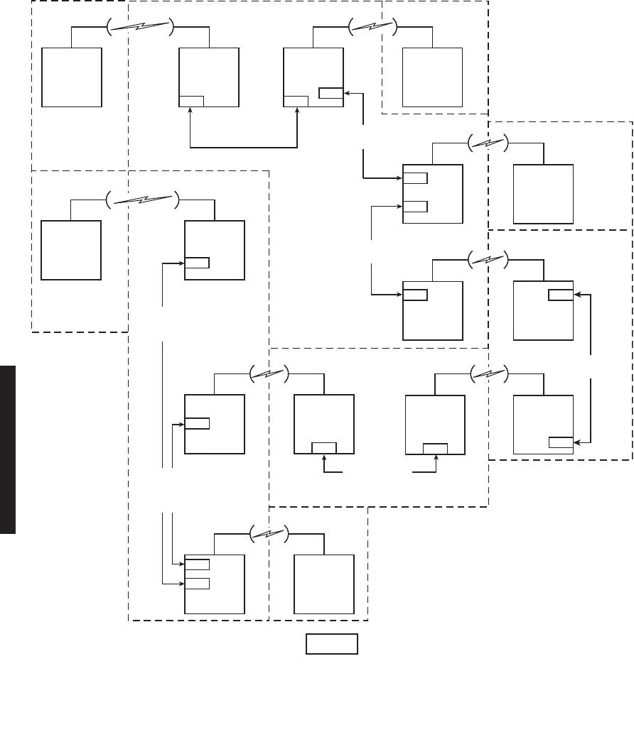
3-40
Figure 3-25 Typical ELMC Connections
B1
TERM.
DS307
MDR-8000
REPEATER CABLE
695-7836-001 THRU -005
695-4125-006/013
CROSSWIRE
A9
MDR-4000E
J102
TERM
MDR-1026
06/12/04
MDR-8000
B2
RPTR
DS308
J401
B5
TERM
DS303
MDR-8000
J315
J318
B7
TERM
DS301
MDR-8000
J318
B4
TERM 4
DS310
MDR-8000
E3A
MDR-6000
TERM
S7341
E4A
MDR-6000
RPTR
T7341
J309
J314
E2A
MDR-6000
RPTR
T7572
J314
MDR-8000
B6
TERM
DS304
E1A
MDR-6000
TERM
G7572
J309
695-4125-006/013
CROSSWIRE
695-4125-006/013
CROSSWIRE
695-4125-006/013
CROSSWIRE
A10
TERM
MDR-4000E
MDR-8000
B8
TERM
DS302
J318
TERM
DS106
J318
MDR-8000
TERM
DS105
J318
MDR-8000
B3
RPTR
DS309
J401
MDR-8000
J318
PIGTAIL
CABLE
695-4125-008
REPEATER
CABLE
372-0456
020/050/070
Note
When connecting MDR-8000 radios with Windows USI to radios with DOS USI, check the
DOS USI ELMC address for space, dash, slash, asterisk, or underscore. The Windows USI
cannot recognize a space, dash, slash, asterisk, or underscore. Change the DOS ELMC
address to a 5-character alphanumeric address without the prohibited characters.
SITE A
SITE B
SITE C SITE G
SITE H
SITE I
SITE D
SITE E
SITE F
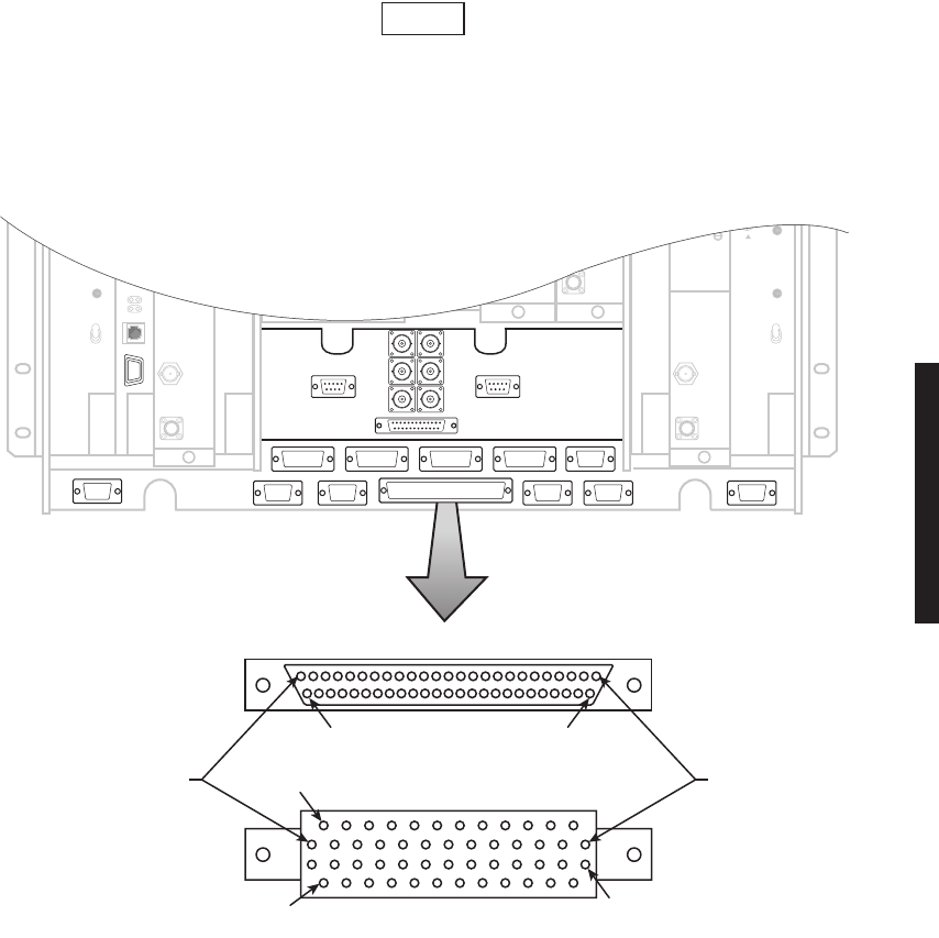
3-41
3.16 FOREIGN ALARM INTERFACE (J305)
Recommended connectorized cable assembly – PN 695-4121-001/003 (24 AWG 25 pair
cable). See Figure 3-26 for shelf connector location and pinout. Refer to Table 3-13 for
mating cable pinout and color code.
or
Recommended wirewrap cable – PN 424-0429-020 (22 AWG 30-pair twisted cable) for use
with wirewrap adapter PN 695-4171-002. Refer to Table 3-14 for pinout.
TBOS connections on J305 share pins with station alarms 13 through
16 and either TBOS or station alarms 13 through 16 is selected (provi-
sioned) on the USI Radio Configuration Provisioning screen.
Figure 3-26 Alarm/Status/TBOS Connector J305 Location and Pinout
Note
J315
J301
J313
J308 J309 J310 J312
J318 J305 J316 J317 J302
J307
24 1
J305
FRONT VIEW
WIRE WRAP ADAPTER
26
26
50
49
25
J305
LMW-7060
07/23/02

3-42
Table 3-14 Alarm/Status Connector J305 Mating Cable Wiring and Pinout
ALM/STATUS/CONTROL
PIN PR WIRE
COLOR
REMARKS
A XMT ALM OUT
01 1 WHT/BLU
ALARM OUTPUT FROM RELAY INTFC
NOT USED*
26 BLU/WHT
N/A
A RCV ALM OUT
02 2 WHT/ORN
ALARM OUTPUT FROM RELAY INTFC
NOT USED*
27 ORN/WHT
N/A
CONTROLLER FAIL ALM OUT
03 3 WHT/GRN
ALARM OUTPUT FROM RELAY INTFC
SWITCH I/O OUT
28 GRN/WHT
CONTROL OUTPUT FROM RELAY INTFC
SWITCH XMTR OUT
04 4 WHT/BRN
CONTROL OUTPUT FROM RELAY INTFC
SWITCH RCVR OUT
29 BRN/WHT
CONTROL OUTPUT FROM RELAY INTFC
A XMT IN SVCE OUT
05 5 WHT/SLT
STATUS OUTPUT FROM RELAY INTFC
NOT USED*
30 SLT/WHT
N/A
A RCV IN SVCE OUT
06 6 RED/BLU
STATUS OUTPUT FROM RELAY INTFC
NOT USED*
31 BLU/RED
N/A
A I/O IN SVCE OUT
07 7 RED/ORN
STATUS OUTPUT FROM RELAY INTFC
NOT USED*
32 ORN/RED
N/A
PWR SUPPLY ALM OUT
08 8 RED/GRN
ALARM OUTPUT FROM RELAY INTFC
NOT USED*
33 GRN/RED
N/A
STATION ALM 9 IN
09 9 RED/BRN RELAY INPUT FROM CUSTOMER
EQUIPMENT
STATION ALM 1 IN
34 BRN/RED
RELAY INPUT FROM CUSTOMER
EQUIPMENT
STATION ALM 10 IN
10 10 RED/SLT
RELAY INPUT FROM CUSTOMER
EQUIPMENT
STATION ALM 2 IN
35 SLT/RED
RELAY INPUT FROM CUSTOMER
EQUIPMENT
STATION ALM 11 IN
11 11 BLK/BLU
RELAY INPUT FROM CUSTOMER
EQUIPMENT
STATION ALM 3 IN
36 BLU/BLK
RELAY INPUT FROM CUSTOMER
EQUIPMENT
STATION ALM 12 IN
12 12 BLK/ORN
RELAY INPUT FROM CUSTOMER
EQUIPMENT
STATION ALM 4 IN
37 ORN/BLK
RELAY INPUT FROM CUSTOMER
EQUIPMENT
TBOS XMT- DATA IN OR
STATION ALM 13 IN
13 13 BLK/GRN
SERIAL DATA INPUT TO RADIO CON-
TROLLER OR INPUT FROM CUSTOMER
EQUIPMENT TO RELAY INTFC CARD
(PROVISIONABLE)
STATION ALM 5 IN
38 13 GRN/BLK
INPUT FROM CUSTOMER EQUIPMENT
TBOS XMT+ DATA IN OR
STATION ALM 14 IN
14 14 BLK/BRN
SERIAL DATA INPUT TO RADIO CON-
TROLLER OR INPUT FROM CUSTOMER
EQUIPMENT TO RELAY INTFC CARD
(PROVISIONABLE)
STATION ALM 6 IN
39 BRN/BLK
INPUT FROM CUSTOMER EQUIPMENT

3-43
TBOS RCV- DATA OUT OR
STATION ALM 15 IN
15 15 BLK/SLT
SERIAL DATA INPUT TO RADIO CON-
TROLLER OR INPUT FROM CUSTOMER
EQUIPMENT TO RELAY INTFC CARD
(PROVISIONABLE)
STATION ALM 7 IN
40 SLT/BLK
INPUT FROM CUSTOMER EQUIPMENT
TBOS RCV+ DATA OUT OR
STATION ALM 16 IN
16 16 YEL/BLU
SERIAL DATA INPUT TO RADIO CON-
TROLLER OR INPUT FROM CUSTOMER
EQUIPMENT TO RELAY INTFC CARD
(PROVISIONABLE)
STATION ALM 8 IN
41 BLU/YEL
INPUT FROM CUSTOMER EQUIPMENT
CONTROL 1 OUT
17 17 YEL/ORN
OUTPUT TO CUSTOMER EQUIPMENT
CONTROL STATUS 1 IN
42 ORN/YEL
INPUT FROM CUSTOMER EQUIPMENT
IN RESPONSE TO CONTROL 1 OUTPUT
CONTROL 2 OUT
18 18 YEL/GRN
OUTPUT TO CUSTOMER EQUIPMENT
CONTROL STATUS 2 IN
43 GRN/YEL
INPUT FROM CUSTOMER EQUIPMENT
IN RESPONSE TO CONTROL 2 OUTPUT
CONTROL 3 OUT
19 19 YEL/BRN
OUTPUT TO CUSTOMER EQUIPMENT
CONTROL STATUS 3 IN
44 BRN/YEL
INPUT FROM CUSTOMER EQUIPMENT
IN RESPONSE TO CONTROL 3 OUTPUT
CONTROL 4 OUT
20 20 YEL/SLT
OUTPUT TO CUSTOMER EQUIPMENT
CONTROL STATUS 4 IN
45 SLTYEL
INPUT FROM CUSTOMER EQUIPMENT
IN RESPONSE TO CONTROL 4 OUTPUT
CONTROL 5 OUT
21 21 VIO/BLU
OUTPUT TO CUSTOMER EQUIPMENT
CONTROL STATUS 5 IN
46 BLU/VIO
INPUT FROM CUSTOMER EQUIPMENT
IN RESPONSE TO CONTROL 5 OUTPUT
CONTROL 6 OUT
22 22 VIO/ORN
OUTPUT TO CUSTOMER EQUIPMENT
CONTROL STATUS 6 IN
47 ORN/VIO
INPUT FROM CUSTOMER EQUIPMENT
IN RESPONSE TO CONTROL 6 OUTPUT
PATH ALM OUT
23 23 VIO/GRN
ALARM OUTPUT FROM CONTROLLER
LOSS OF INPUT OUT
48 GRN/VIO
ALARM OUTPUT FROM CONTROLLER
MAJOR ALM/VISUAL ALM
OUT
24 24 VIO/BRN
ALARM OUTPUT FROM CONTROLLER
(PROVISIONABLE MAJOR/MINOR OR
VISUAL/AUDIBLE ON USI SCREEN)
RACK ALM RETURN
49 VIO/BRN
INPUT TO CONTROLLER
RACK ALM OUT
25 25 VIO/SLT
OUTPUT FROM CONTROLLER
MINOR ALM/AUDIBLE ALM
OUT
50 SLT/VIO
ALARM OUTPUT FROM CONTROLLER
(PROVISIONABLE MAJOR/MINOR OR
VISUAL/AUDIBLE ON USI SCREEN)
*Wired but not used
Table 3-14 (Cont.) Alarm/Status Connector J305 Mating Cable Wiring and Pinout
ALM/STATUS/CONTROL
PIN PR WIRE
COLOR
REMARKS

3-44
3.17 ALARM, STATUS, CONTROLS INTERCONNECT
See Figure 3-27 for interconnect diagram. The AE-27( ) Relay Interface provides alarm,
control and status inputs, and alarm, status and control relay outputs. All output relays
can be disabled or provisioned normally open or normally closed as follows:
Normally open (NO) – relays are normally de-energized and relay contacts are open. When
activated, relays are energized. Relay contacts close, connecting the output to ground.
Normally closed (NC) – relays are normally energized and relay contacts are closed and
grounded. When activated, relays are de-energized. Relay contacts open, presenting an
open (high impedance) to the output.
Rack ALM Return, Pin 49 is a ground point for use with Rack ALM Out. It is a signal
ground (low current) not used for battery voltage or high current ground.
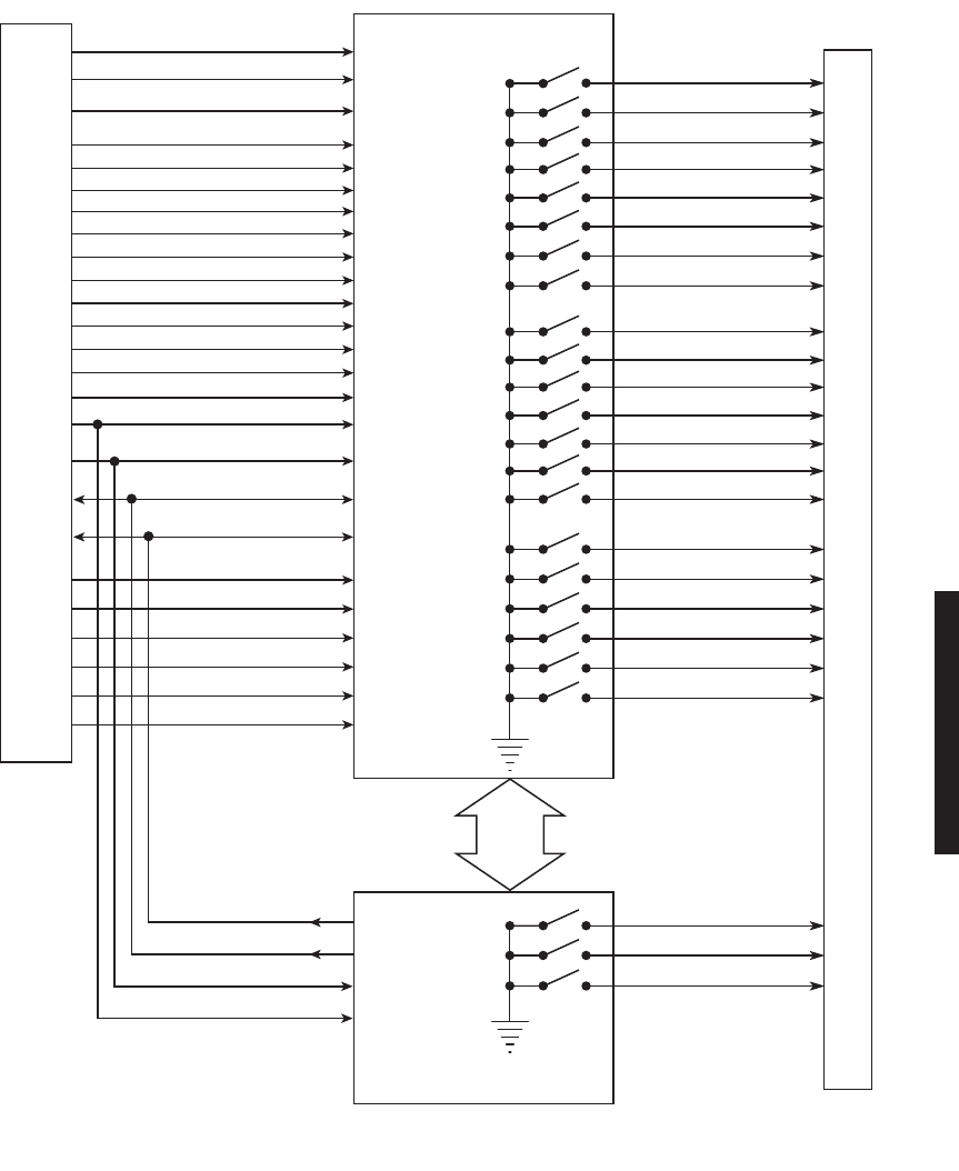
3-45
Figure 3-27 Alarm and Status Relays/TBOS Interconnect
SWITCH XMTR
PATH ALM
J305
J305
RELAY
INTERFACE
CONTROLLER
NOTE: ALL RELAY CONTACTS
ARE SHOWN AS SWITCHES
FOR DOCUMENTATION
PURPOSES.
*
PROVISIONABLE TBOS TO/FROM CONTROLLER
OR STATION ALARM 13-16 TO RELAY INTFC
LMW-7064
5/12/04
SWITCH RCVR
SWITCH I/O
STATION ALM 1
STATION ALM 2
STATION ALM 3
STATION ALM 4
STATION ALM 5
STATION ALM 6
CONTROL STATUS 1
CONTROL STATUS 2
CONTROL STATUS 3
CONTROL STATUS 4
CONTROL STATUS 5
CONTROL STATUS 6
TBOS RCV -*
TBOS RCV +*
TBOS XMT -*
TBOS XMT +*
STATION ALM 7
STATION ALM 8
STATION ALM 9
STATION ALM 10
STATION ALM 11
STATION ALM 12
STATION ALM 13*
STATION ALM 14*
STATION ALM 15 IN*
STATION ALM 16 IN*
LOSS OF INPUT ALM
A XMT ALM
B XMT ALM
A RCV ALM
B RCV ALM
POWER SUPPLY ALM
CONTROLLER FAIL
A XMTR IN SERV
B XMTR IN SERV
A RCVR IN SERV
B RCVR IN SERV
A I/O IN SERV
B I/O IN SERV
SW OFF NORMAL
CONTROL 1
CONTROL 2
CONTROL 3
CONTROL 4
CONTROL 5
CONTROL 6
MAJOR / VISUAL ALM
MINOR / AUDIBLE ALM
RACK ALM
DATA
CONTROL

3-46
3.17.1 Controller Bus
The Relay Interface communicates with the AE-37( ) Controller card via the processor bus
and the data bus. The processor bus, consisting of three address lines, two control lines,
and a clock, is applied to a XCVR. The data bus contains the eight data lines (D0-D7) and
is applied to a separate transceiver. Interface with the relay transceivers is provided by the
XCVR data bus. When commanded by the AE-37( ) Controller, the decoder/DEMUX
decodes and demultiplexes the address and enables the appropriate relay XCVR via the
EN2-9 controls. The controller can then write alarm/status/control information to the relay
XCVRs, or read alarm/status/control inputs from the relay XCVRs. Further descriptions of
the controller interface signals follow:
• Address lines A0 through A3 – HCMOS inputs. 100K Ohm pull-ups. Used by address
decoders to enable output registers and input buffers.
• Buffered bidirectional data lines D0 through D7 – HCMOS input/outputs. 10K Ohm
pull-ups. Used to write data to output registers and read present bits or data from
input buffers.
• ECLK – 2 MHz bus clock. HCMOS input. 100K Ohm pull-up.
• R/WF Read/Write False. HCMOS input. 100K Ohm pull-up. A logic 1 indicates data is
being read from an input buffer or the present bits. A logic 0 indicates data is being
written to an output register.
•Relay Intfc CSF – Relay Interface Card Select False. HCMOS input. 100K Ohm pull-up.
Chip select for relay interface card. Active low.
3.17.2 Control Inputs
Nine buffered control inputs are provided. The inputs are diode protected from voltages out-
side of the 0 to +5 V range, and have a 10K Ohm resistor for current limiting purposes. In
addition, each input has a 100K Ohm pull-up resistor.
• Switch Transmitter (SWITCH TX) – buffered HCMOS input, sends signal to controller
module to activate the transmitter that is currently not carrying traffic.
• Switch Receiver (Switch RX) – buffered HCMOS input, sends signal to controller mod-
ule to activate the receiver that is currently not carrying traffic.
•Switch I/O Interface (SWITCH I/O) – buffered HCMOS input, sends signal to controller
module to activate the stand-by I/O interface module.
3.17.3 Station Alarm Inputs/TBOS Interface
Each radio shelf can accept/report up to 12 different user-defined station-type alarms, and, if
provisioned
Station Alarm 13-16
, the radio can accept an additional four station alarms, for a
total of 16. Station alarms 13 through 16 share pins on connector J305 with the four TBOS
inputs and outputs. TBOS inputs and outputs are enabled by software when the radio is provi-
sioned
TBOS Display 1-8
. When TBOS is enabled station alarms 13 through 16 are disabled.
The alarm/status input signals are buffered HCMOS inputs, diode protected from voltages
outside of the 0 to +5 V range, with 10 kilohm current limiting (series) resistor and 100
kilohm pull-up resistor. A logic 0 indicates an alarm state. A logic 1 (or open) indicates a
non-alarm state.
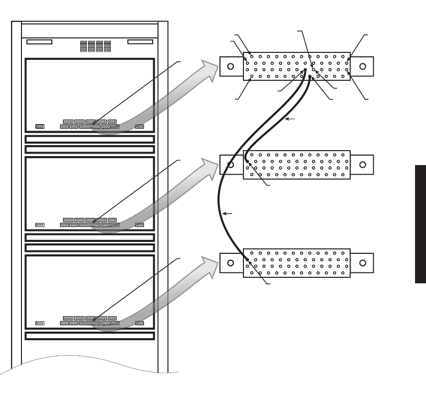
3-47
3.17.4 Station Alarm Wiring
See Figure 3-28. Use wire wrap adapter PN 695-4171-002 to connect station alarm inputs
to the AE-27A Relay Interface module, via connector J305, in each rack. A typical connec-
tion scenario is shown. The station/shelf alarm for MCS-11 address A1A (MCS-11 alarm
point 1) is connected by software. The station alarms for MCS-11 address A1B and A1C are
assigned to MCS-11 Alarm points 2 and 3, respectively.
Figure 3-28 Alarm and Status Relays/TBOS Interconnect
M
CS
-11
ADDRE
SS
A1A
MDR-8000 SHELF
FAN A
SSY
HEAT DEFLE
C
T
O
R
M
CS
-11
ADDRE
SS
A1B
MDR-
8000
S
HELF
FAN A
SSY
HEAT DEFLE
C
T
O
R
M
CS
-11
ADDRE
SS
A1
C
MDR-
8000
S
HELF
FAN A
SSY
P
D
U
J30
5
J30
5
NOTE
SOFTWARE AUTOMATICALLY CONNECTS
RACK ALM OUTPUT FROM CONTROLLER
J305-25 TO #1 STATION ALM INPUT J305-24.
J30
5
25RA
C
K AL
M
PIN 1
26
34
36
35
PIN 25
RACK ALM
PIN 25
RACK ALM
4
9
24
#1 STATION
ALM
WIRE WRAP ADAPTER
(PN 695-4171-002)
#
3
STATION
ALM
#2 STAT I O N
ALM
(SEE NOTE)
LMW-
8002
07/28/02

3-48
3.17.5 Relay Alarm/Status Outputs
Eight alarm relay outputs and seven status relay outputs provide relay closure to ground
(provisioned NO) or open (provisioned NC) when activated. All relays default to open if
card power is lost, except the Power Supply alarms, which default to ground. The maxi-
mum contact rating for each relay is 0.5 A, 100 Vdc. The alarm/status relay outputs are:
• Alarms:
•Path Alarm– This summary alarm is activated by the following alarms:
A/B Path Distortion
A/B AGC Threshold
• Loss of Input Alarm– This summary alarm is activated by the following alarms:
Loss of DS3 input
Loss of optical input (OC3)
Loss of wayside DS1 input
•A XMT – A-side transmitter failure. This summary alarm is activated by any of the
following alarms on the A side:
XMT SYNC Alarm
RF Power Alarm
Common Loss Alarm
ATPC Timeout
MUX Input Loss Alarm
•B XMT – B-side transmitter failure. This summary alarm is activated by any of the
following alarms on the B side:
XMT SYNC Alarm
RF Power Alarm
Common Loss Alarm
ATPC Timeout
MUX Input Loss Alarm

3-49
•A RCV – B-side receiver failure. This summary alarm is activated by any of the fol-
lowing alarms on the A side:
Channel Alarm
RCV Frame Loss
Eye Closure
RSL Alarm
•B RCV – B-side receiver failure. This summary alarm is activated by any of the fol-
lowing alarms on the B side:
Channel Alarm
RCV Frame Loss
Eye Closure
RSL Alarm
•PWR Supply Alarm – This summary alarm is activated by any A or B power supply
failure.
• Controller Fail – relay is activated if a card select has not been detected in the pre-
vious approximately 200 msec.
• Status:
•A XMTR In Service – A-side transmitter module is on-line.
•B XMTR In Service – B-side transmitter module is on-line.
•A RCVR In Service – A-side receiver module is on-line.
•B RCVR In Service – B-side receiver module is on-line.
•A I/O In Service – A-side I/O interface module is on-line.
•B I/O In Service – B-side I/O interface module is on-line.
• Switch Off Normal – Click on OFF NORM LED on USI Status Alarm screen to
view message. Indicates manual control enabled or one of following conditions
exists:

3-50
OFF NORMAL MESSAGE DISPLAYED ON USI STATUS ALARM SCREEN:
A/B Side PA Off – PA ON/OFF switch on A or B power supply is set to OFF.
A/B Side LIO SPI Fail – XMT or RCV circuit failure on Low Capacity I/O ASIC in A or B
DS1 I/O interface module.
A/B Side RCV SPI Fail – Failure on the Serial Processor Interface bus causing loss of com-
munication between the controller and RCV circuits on the I/O interface module.
A/B Side DS1 SPI Fail – Failure on the Serial Processor Interface bus causing loss of com-
munication between the controller and DS1 interface circuits on the I/O interface module.
Fan Alarm – Failure of one or more cooling fans or failure of the fan control module on the
fan assembly.
I/O Loopback On – I/O LOOPBACK function is enabled on USI control screen.
DS1 Line 1-3 Loopback On – DS1 LINE LOOPBACK RCV to XMT 1-3 function is enabled
on USI control screen.
A/B RCV Prov. ERROR UNIRCV – Failure in communication between processor on con-
troller and UNIRCV ASIC on DS3 I/O interface module.
A/B DS1 Prov. ERROR LEGHORN – Failure in communication between processor on con-
troller and Leghorn ASIC on I/O interface module.
A/B ATPC LOW POWER LOCK – A or B Automatic Transmit Power Control low power
lock function is enabled on USI control screen on DS1, DS3, or OC3 radio. Lock prevents
ATPC from going high.
A/B ATPC HIGH POWER LOCK – A or B Automatic Transmit Power Control high power
lock function is enabled on USI control screen on DS1, DS3, or OC3 radio. Lock prevents
ATPC from going low.
EEPROM PROV DOES NOT MATCH MODULE PROV – Stored provisioning in controller
memory does not match provisioning stored in module memory.
XMTR Capacity Key Mismatch – Part numbers of capacity keys on A and B XMTRs are
different.

3-51
RCVR Capacity Key Mismatch – Part numbers of capacity keys on A and B RCVRs are
different.
A/B Tx OVERRIDE – A or B XMTR has been switched and locked in-service using controls
on the front panel of the controller module. Online XMTR will not switch out-of-service
regardless of alarms.
A/B Rx OVERRIDE – A or B RCVR has been switched and locked in-service using controls
on the front panel of the controller module. Online RCVR will not switch out-of-service
regardless of alarms.
A/B I/O OVERRIDE – A or B I/O interface has been switched and locked in-service using
controls on the front panel of the controller module. Online I/O interface will not switch
out-of-service regardless of alarms.
3.17.6 Relay Control Outputs
Control outputs and control status inputs operate together to perform
control functions. The control status inputs to the relay interface must
be properly wired to the external equipment that is being controlled by
the associated control output in order to display the ON or OFF status
on the USI control screen. Without the control status inputs, the control
function on the USI screen will still turn on equipment/functions, but
no status will be indicated and, once turned on, the equipment/func-
tion cannot be turned off.
Six relay control outputs (CTRL 1-6) provide relay closure to ground (provisioned NC) or
open (provisioned NO) when activated. These relays default to open if card power is lost.
The maximum contact rating for each relay is 0.5 A, 100 Vdc.
Nine buffered status inputs (CTRL STATUS 1-6) from the equipment controlled by the
CTRL 1-6 outputs, verifying the controlled function. The inputs are diode protected from
voltages outside of the 0 to +5 V range, and have a 10K Ohm resistor for current limiting
purposes. In addition, each input has a 100K Ohm pull-up resistor.
Note

3-52 This page intentionally left blank.