Alien Technology ALRF800B RFID Reader User Manual
Alien Technology, LLC RFID Reader
Contents
- 1. User Manual
- 2. Users Manual
- 3. Users Manual (Multiplexer)
User Manual

ALIEN TECHNOLOGY®
ALR-F800
HARDWARE
SETUP GUIDE
June 2015
ALR-F800

Legal Notices
Copyright ©2015 Alien Technology Corporation. All rights reserved.
Alien Technology Corporation has intellectual property rights relating to technology embodied in the products
described in this document, including without limitation certain patents or patent pending applications in the U.S. or
other countries.
This document and the products to which it pertains are distributed under licenses restricting their use, copying,
distribution and de-compilation. No part of this product documentation may be reproduced in any form or by any
means without the prior written consent of Alien Technology Corporation and its licensors, if any. Third party software
is copyrighted and licensed from Licensors. Alien, Alien Technology, the Alien logo, Higgs, Squiggle, the Squiggle
logo, and other graphics, logos, and service names used in this document are trademarks of Alien Technology
Corporation in the U.S. and other countries. All other trademarks are the property of their respective owners. U.S.
Government approval required when exporting the product described in this documentation.
Federal Acquisitions: Commercial Software -- Government Users Subject to Standard License Terms and Conditions.
U.S. Government: If this Software is being acquired by or on behalf of the U.S. Government or by a U.S. Government
prime contractor or subcontractor (at any tier), then the Government's rights in the Software and accompanying
documentation shall be only as set forth in this license; this is in accordance with 48 C.F.R. 227.7201 through
227.7202-4 (for Department of Defense (DoD) acquisitions) and with 48 C.F.R. 2.101 and 12.212 (for non-DoD
acquisitions).
DOCUMENTATION IS PROVIDED “AS IS” AND ALL EXPRESS OR IMPLIED CONDITIONS, REPRESENTATIONS
AND WARANTEES, INCLUDING ANY IMPLIED WARRANTY OF MERCHANTABILITY, FITNESS FOR A
PARTICULAR PURPOSE OR NON-INFRINGMENT ARE HEREBY DISCLAIMED, EXCEPT TO THE EXTENT THAT
SUCH DISCLAIMERS ARE HELD TO BE LEGALLY INVALID.
FCC Compliance
This equipment has been tested and found to comply with the limits for Class A digital device, pursuant to Part 15 of
the FCC Rules. These limits are designed to provide reasonable protection against harmful interference when the
equipment is operated in a commercial environment. This equipment generates, uses and can radiate radio
frequency energy and, if not installed and used in accordance with instruction manual, may cause harmful
interference with radio communications. Operation of this equipment in a residential area is likely to cause harmful
interference in which case the user will be required to correct the interference at his expense.
Any change or modification to this product voids the user’s authority to operate per FCC Part 15 Subpart A. Section
15.21 regulations.
Industry Canada Compliance
Operation is subject to the following two conditions: (1) this device may not cause interference and (2) this device
must accept any interference, including interference that may cause undesired operation of the device.
This device has been designed to operate with an antenna having a maximum gain of 6dBi. Antenna having a higher
gain is strictly prohibited per regulations of Industry Canada. The required antenna impedance is 50 ohms.
To reduce potential radio interference to other users, the antenna type and its gain should be so chosen that the
equivalent isotropically radiated power (EIRP) is not more than that required for successful communication.
Caution
Reader antennas should be positioned so that personnel in the area for prolonged periods may safely remain at least
23 cm (9 in) in an uncontrolled environment from the antenna’s surface. See FCC OET Bulletin 56 “Hazards of radio
frequency and electromagnetic fields” and Bulletin 65 “Human exposure to radio frequency electromagnetic fields.”

TABLE OF CONTENTS
ALR-F800 HARDWARE SETUP GUIDE
DOC. CONTROL #8102141-000 REV A i
Alien Technology®
Hardware Setup Guide
ALR-F800
June 2015
Table of Contents
CHAPTER 1 INTRODUCTION ..................................................................................................................... 1
RFID Reader Overview ................................................................................................................................. 1
EPC Class 1 GEN 2 UHF RFID Tags ........................................................................................................... 2
Requirements ................................................................................................................................................ 2
Specifications ................................................................................................................................................ 3
RFID Reader ........................................................................................................................................... 3
RFID Reader High Performance Circular Antenna ................................................................................ 4
Mechanical: Reader Physical Size ........................................................................................................ 4
I/O Port Terminal Interface ..................................................................................................................... 4
RS-232 Port Pin-outs .............................................................................................................................. 6
RS-232 Connector (Female) – Looking at Reader .......................................................................... 6
Power Supplies ....................................................................................................................................... 7
System Architecture ............................................................................................................................... 8
CHAPTER 2 READER HARDWARE INSTALLATION AND OPERATION ................................................ 9
Receiving the RFID Reader .......................................................................................................................... 9
Reader I/O Panel .................................................................................................................................. 10
Diagnostic LEDs ................................................................................................................................... 11
Reader Antennas ........................................................................................................................................ 12
System Assembly and Bench Test ............................................................................................................. 12
Bench Test Configuration ..................................................................................................................... 12
Bench Test Procedure .......................................................................................................................... 16
Installation ................................................................................................................................................... 16
Requirements ....................................................................................................................................... 17
Hardware Installation Procedure .......................................................................................................... 17
System Operation: Software Control .......................................................................................................... 19
Reader Interface Guide ........................................................................................................................ 20
Demonstration Software Guide ............................................................................................................ 20
Alien RFID Academy ............................................................................................................................ 20

CHAPTER 1 INTRODUCTION
ALR-F800 HARDWARE SETUP GUIDE
DOC. CONTROL #8102141-000 REV A 1
CHAPTER 1
Introduction
This Hardware Setup Guide provides instructions for installing and operating the
ALR-F800 RFID Readers.
This document is designed for use by RFID system integrators and software
developers - those who wish to develop software products and extended systems
that take full advantage of the RFID Reader's capabilities.
Included with each developer’s kit is a Download instructions that contains
additional information about RFID and the ALR-F800 including the following:
RFID Primer – an overview of RFID technology and a glossary of terms.
Reader Interface Guide – an overview of the communication interfaces
for the ALR-F800.
Quick Installation Guide – a quick start guide for installing and running
the ALR-F800 reader
Quick Reference – a quick reference guide summarizing the Alien
Reader Protocol command set.
Demo Software Guide – details installing and operating the Alien RFID
Gateway demonstration software.
Quick Upgrade Guide – briefly explains how to use the demonstration
software to upgrade the ALR-F800. The ALR-F800 can only be upgraded
through the LAN/PoE port.
Developer’s Guides, Application Programming Interfaces and Example
Code.
RFID Reader Overview
The Alien ALR-F800 RFID reader is designed to read and program any EPC
Class 1 Generation 2 tag and issue event reports to a host computer system.
The host computer can be locally connected to the reader via RS-232,serial over
USB or at a remote network location. It is designed to accept power through an
IEEE 802.3af compliant network or a conventional 12 Volt DC power source.
The RFID Reader is delivered with the following components:
One (1) RFID Reader
The RFID Reader Kit is delivered with the following components and
accessories:
One (1) RFID Reader
One (1) PoE power supply
One (1) AC power cord
One (1) standard network cable to connect the PoE power supply to the
reader.

CHAPTER 1 INTRODUCTION
ALR-F800 HARDWARE SETUP GUIDE
DOC. CONTROL #8102141-000 REV A 2
Additionally, the RFID Reader Developer's Kit includes the following items:
One (1) ALR-8696-C antenna
One (1) RS-232 serial cable (to connect to host computer)
One (1) Network cross-over cable
Download instructions for demonstration software, user guides,
documentation and the Alien RFID Gateway Application
Software APIs and example code
An assortment of Class 1 Gen 2 UHF tags
EPC Class 1 GEN 2 UHF RFID Tags
The Alien ALR-F800 RFID reader is designed to read and program any EPC
Class 1 Generation 2 tag and issue event reports to a host computer system.
Class 1 tags are “passive” devices meaning they do not have a battery or other
onboard power source. They are powered solely by the RF energy transmitted by
an RFID reader.
Tags communicate with the reader through backscatter modulation. The tags do
not transmit RF energy. Instead, they change their reflective characteristics in a
controlled way and reflect RF energy back to the reader. An analogy to this is the
way you can use a mirror to signal someone by reflecting light from the Sun.
Alien Technology manufactures user-programmable EPC Class 1 Generation 2
tags compliant with all key commercial and DoD mandates. Alien Technology
offers a variety of designs capable of delivering optimal performance worldwide,
including Europe and Asia.
For more information about RFID tags from Alien Technology, please visit our
website at:
http://www.alientechnology.com.
Requirements
To interface with the RFID Reader you will need the following:
A PC running Windows 98 or higher, with CD-ROM drive, an available
RS-232 serial port and/or Ethernet connectivity and/or USB.
An 802.3af compatible network connection, or
Standard 120/220 VAC 50/60 Hz outlet and the POE power supply
(provided with the reader kit) or DC power cable.
Note: Only these supplies may be used to power the ALR-F800.
Host software (Alien Gateway demo software, telnet terminal or your own
custom software)

CHAPTER 1 INTRODUCTION
ALR-F800 HARDWARE SETUP GUIDE
DOC. CONTROL #8102141-000 REV A 3
Specifications
Specifications for key components of the RFID Reader system are provided in
the tables below. Only these listed components may be used in the RFID reader
system.
The reader table refers to US specifications only. Reader models released for the
other countries may have different power levels, frequency of operation and
channel spacing in compliance with local regulations where the product is sold.
RFID Reader
Name Alien Multi-Port General Purpose RFID Reader
Model Number ALR-F800
Architecture Point-to-multipoint reader network, mono-static
Operating Frequency 902.75 MHz – 927.25 MHz
Hopping Channels 50
Channel Spacing 500 KHz
Channel Dwell Time < 0.4 seconds
RF Transmitter < 30 dBm from antenna ports.
Modulation Method Phase Reversal – Amplitude Shift Keying (PR-ASK)
20 db Modulation Bandwidth < 100 KHz
RF Receiver 2 Channels
Power Consumption 12.5 Watts
Communications Interface RS-232 (DB-9), TCP/IP (RJ-45) , USBB virtual Com
Inputs/Outputs 4 coax antenna, 4 inputs / 8 outputs (optically isolated), RS-232 com
port, USBB virtual Com, LAN / PoE, power, USBA, SDCard
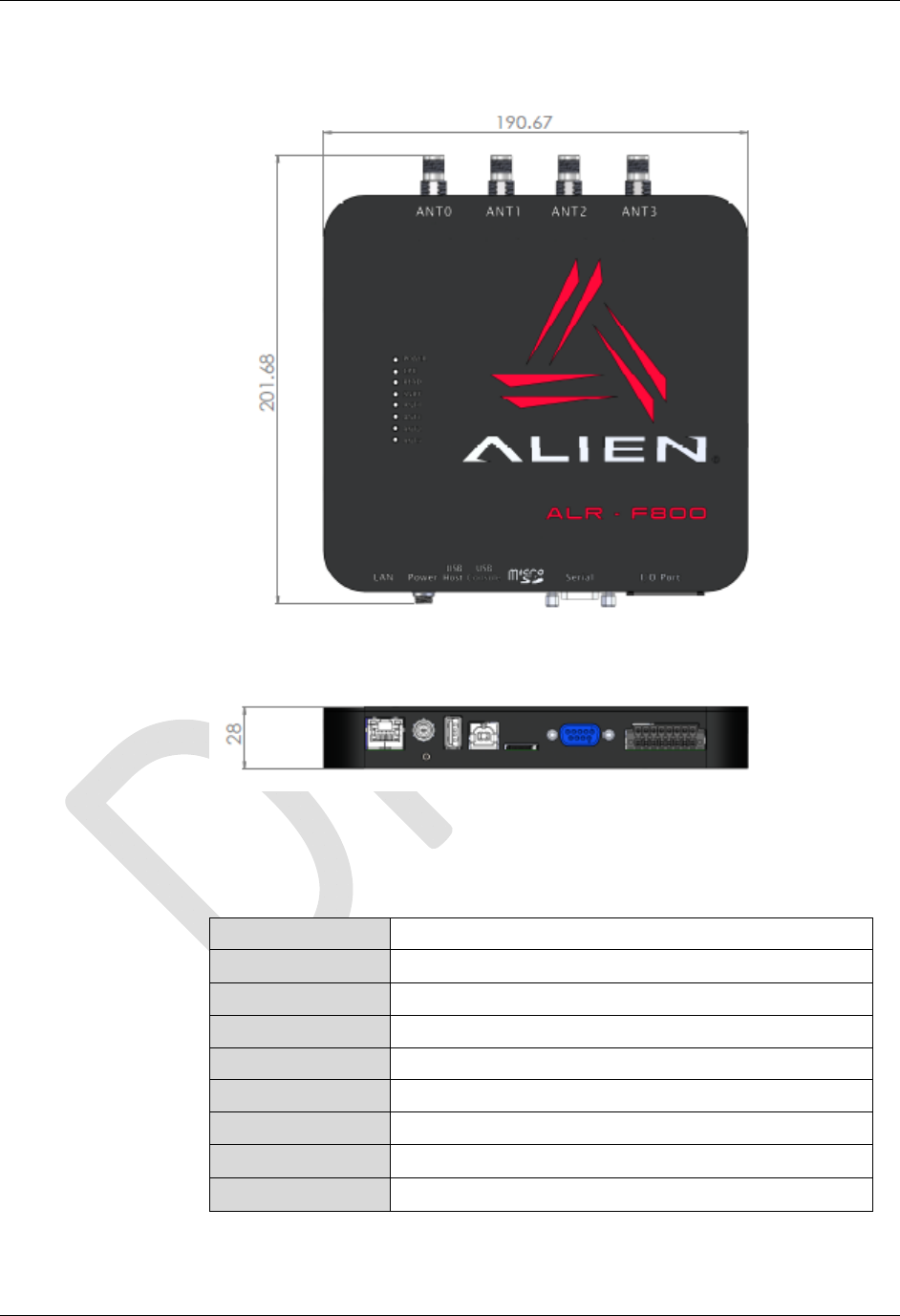
Dimensions (cm) 19.1 x 20.2 x 2.8 (in)7.5 x7.0x 1.0
Weight Approximately 0.84 kg (1.85 lbs)
LED Indicators DC Power, RF ON, Read, Fault(red), Link, Active , Antennas 0-3
Operating Temperature -20°C to +55°C (-5 °F to +130°F)
Operating Environment Indoor operation only
Software Support APIs, sample code, executable demo app (Alien Gateway)
Protocol Support Comply with EPC Class 1 Gen 2 and 18000 – 6C
Compliance Certifications FCC Part 15; FCCID: P65ALRF800;
IOC: 4370A-ALRF800
UL 60950, CB Report
CHAPTER 1 INTRODUCTION
ALR-F800 HARDWARE SETUP GUIDE
DOC. CONTROL #8102141-000 REV A 4
Mechanical: Reader Physical Size
Figure 1 - Outline Drawing of the ALR-F800 (mm)
RFID Reader High Performance Circular Antenna
Model ALR-8696-C
3 dB Beamwidth E-plane: 65 degrees H-plane: 65 degrees
Frequency 865-960 MHz
Gain (dBi) 6.0 dBiL (maximum)
Polarization Circular
RF Connector 6 m LMR-195 with Reverse-Polarity TNC
VSWR 1.5:1
Dimensions (cm) 26 x 26 x 3.4 (in) 10.2 x 10.2 x 1.32
Weight 1.1 kg 2.5 lb

CHAPTER 1 INTRODUCTION
ALR-F800 HARDWARE SETUP GUIDE
DOC. CONTROL #8102141-000 REV A 5
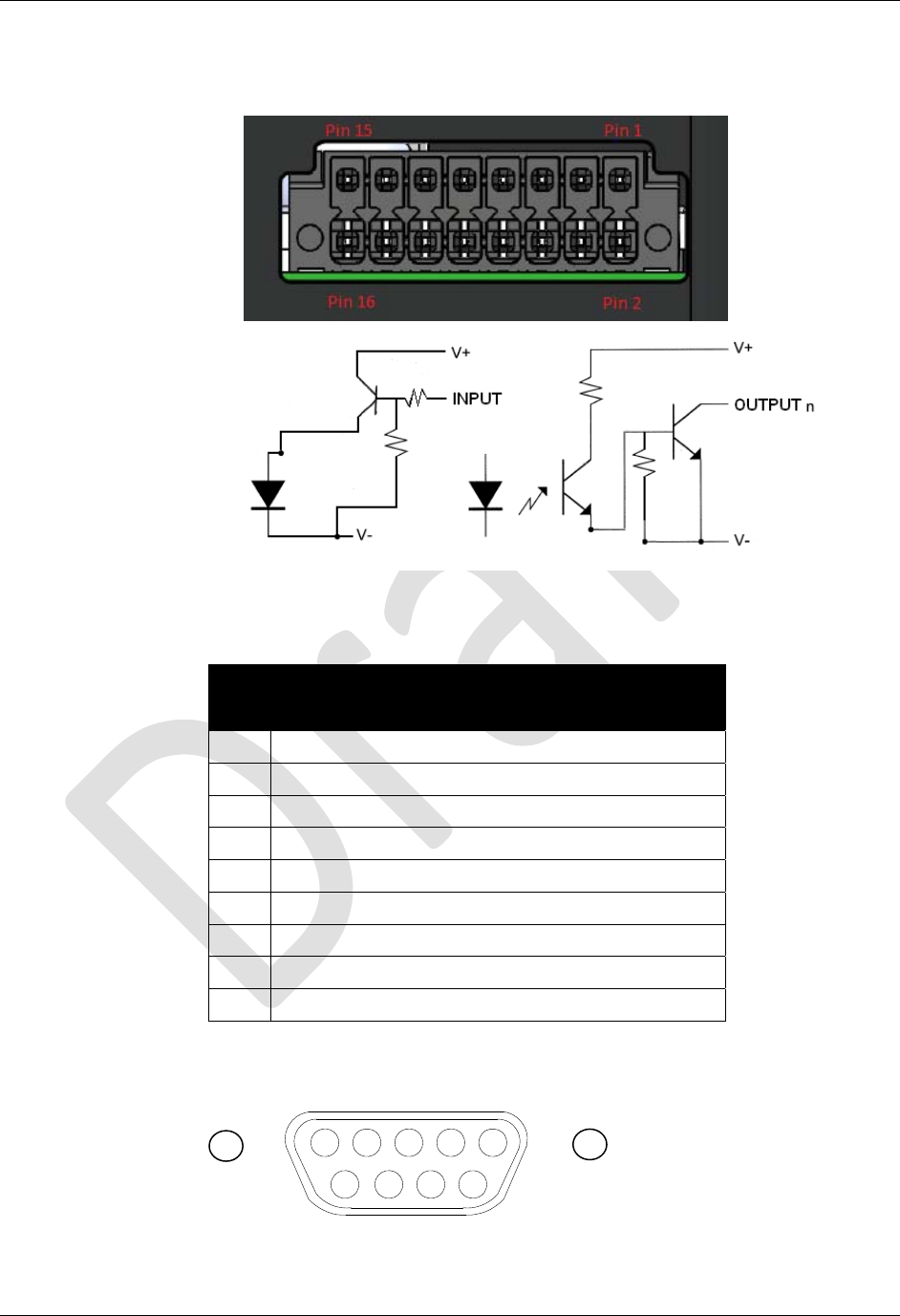
I/O Port Terminal Interface
The ALR-F800 I/O port provides four digital inputs and eight digital outputs,
optically isolated from the reader circuitry for use in noisy industrial
environments. Opto-isolators have two basic elements: a light source (usually a
light emitting diode) and a photo-sensitive detector. These two elements are
positioned facing one another and inserted in an electrical circuit to form an opto-
coupler. The key property of an opto-coupler is that there is an insulating gap
between the light source and the detector. No current passes through this gap,
only the desired light waves representing data. Thus the two sides of the circuit
are electrically isolated from one another.
This protects the circuitry inside the reader from damaging ground loops (when
the external device is at a different ground potential than the reader), and voltage
spikes.
The external device must supply the V+ and V- voltage references.
Alternatively if isolation is NOT required an internal 12V power source is supplied
and can be routed to the V+ and V- pins with a jumper wire. This is only available
if the unit is powered by the DC source jack.
I/O Port Screw Terminal Connector
(Phoenix 14-pin header)
Pin 1 V+ (5-24 VDC External)
Pin 2 V- (Return External)
Pin 3 Output 0 (1.5A max; 7.3A total)
Pin 4 Output 1 "
Pin 5 Output 2 "
Pin 6 Output 3 "
Pin 7 Output 4 "
Pin 8 Output 5 "
Pin 9 Output 6 "
Pin 10 Output 7 "
Pin 11 Input 0 (5-24 VDC)
Pin 12 Input 1 "
Pin 13 Input 2 "
Pin 14 Input 3 "
Pin 15 Internal Fused 12.0 VDC
Pin 16 Chassis GND
CHAPTER 1 INTRODUCTION
ALR-F800 HARDWARE SETUP GUIDE
DOC. CONTROL #8102141-000 REV A 6
I/O PORT SCREW TERMINAL (FEMALE) – LOOKING AT READER
Figure 2 - Input and Output Circuits
RS-232 Port Pin-outs
RS-232 Connector
(Female DB-9F)
Pin 1 DCD Connected to Pin 6
Pin 2 TR1 Transmit Data (Output)
Pin 3 RC1 Receive Data (Input)
Pin 4 DTR Connected to Pin 6
Pin 5 Ground
Pin 6 DSR Connected to Pin 4
Pin 7 RTS Connected to Pin 8
Pin 8 CTS Connected to Pin 7
Pin 9 Not Connected
RS-232 CONNECTOR (FEMALE) – LOOKING AT READER
Figure 3 - RS-232 Connector
54321
9 8 7 6

CHAPTER 1 INTRODUCTION
ALR-F800 HARDWARE SETUP GUIDE
DOC. CONTROL #8102141-000 REV A 7
USB Ports
There two USB ports on the back of the ALR-F800 reader USB-A and USB-B.
They are both female connectors and their functionality is as follows:
USB-A is used to connect various USB devices including USB flash
drives, Wi-Fi and Bluetooth adapters.
USB-B is used as a serial console for either Alien Reader Protocol
interface or Linux OS login.
Power Supplies
The ALR-F800 has been certified to operate in accordance with FCC or other
national requirements when powered by an 802.3af compliant network capable of
supplying 12.95 watts minimum, or by using one of the power supplies listed
below. Only the power supplies listed below may be used with the ALR-F800
reader.
ALR-F800, CORD PACK Power over Ethernet (PoE) Power Supply
CHAPTER 1 INTRODUCTION
ALR-F800 HARDWARE SETUP GUIDE
DOC. CONTROL #8102141-000 REV A 8
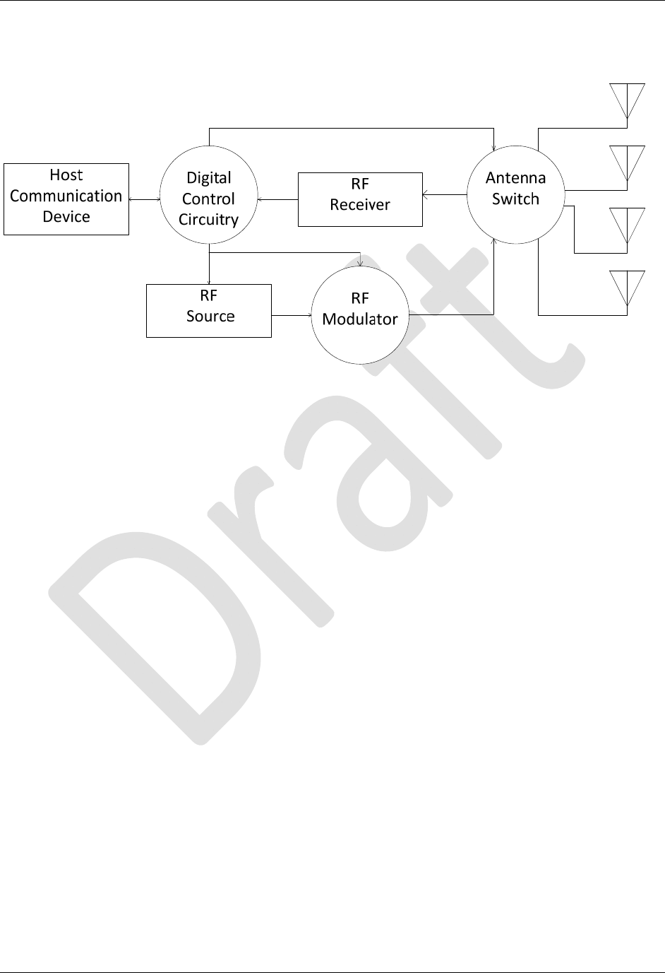
System Architecture
Ant0Ant1Ant2Ant3
Figure 4 - System Architecture for the ALR-F800 Reader

CHAPTER 2 READER HARDWARE INSTALLATION AND OPERATION
ALR-F800 HARDWARE SETUP GUIDE
DOC. CONTROL #8102141-000 REV A 9
CHAPTER 2
Reader Hardware Installation and Operation
This chapter describes the RFID Reader and provides installation and operation
information.
Receiving the RFID Reader
Your RFID Reader is shipped with the items listed below. Please verify the
contents of your received shipment before assembling.
RFID reader
The RFID Reader Kit is shipped with the items listed below.
RFID reader
ALR-F800 Cord Pack which includes the PoE power supply, AC power
cable and standard Ethernet cable.
Additionally, the RFID Reader Developer's Kit includes the following items:
An ALR-8696-C antenna
RS-232 reader-to-PC cable
One Ethernet cross-over cable for direct connection to a local host/PC
Download instructions for demonstration software, user guides,
documentation, Software APIs and example code
An assortment of Class 1 Gen 2 UHF tags
CHAPTER 2 READER HARDWARE INSTALLATION AND OPERATION
ALR-F800 HARDWARE SETUP GUIDE
DOC. CONTROL #8102141-000 REV A 10
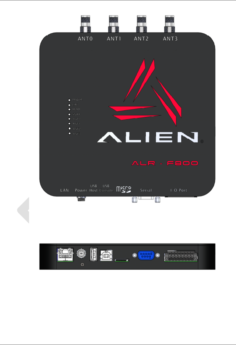
Figure 5 - ALR-F800 Reader (Antennas and tag kit not shown)
Reader Antenna Panel
4 Antenna Ports (RP-TNC)
CHAPTER 2 READER HARDWARE INSTALLATION AND OPERATION
ALR-F800 HARDWARE SETUP GUIDE
DOC. CONTROL #8102141-000 REV A 11
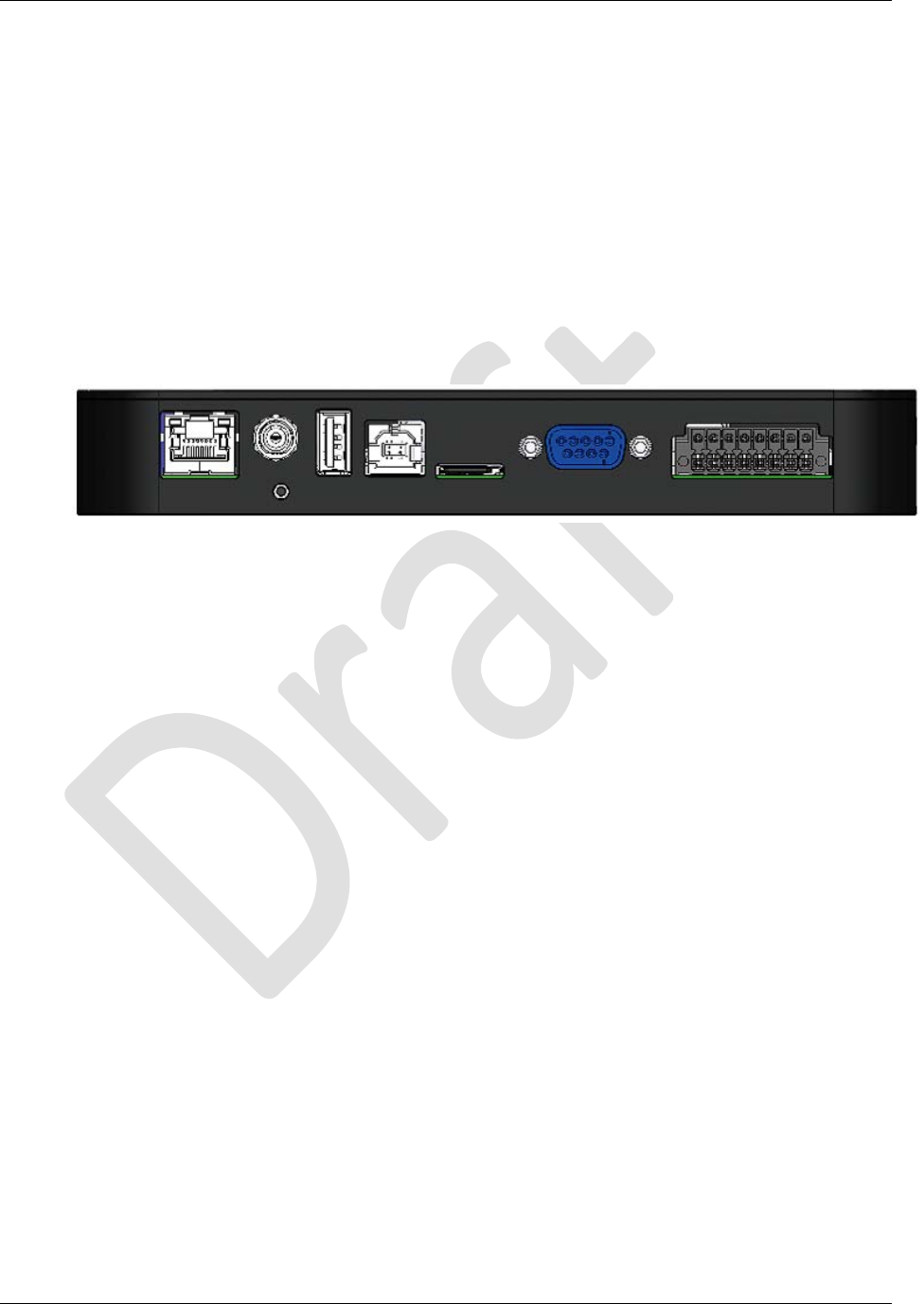
Reader I/O Panel
The I/O panel (shown below) includes the following( Left to Right):
LAN TCP/IP and PoE port
Auxiliary DC Power connector
Reset button
USB A
USB B
SDCard
9-pin D female RS-232 serial port
16-pin I/O terminal block (GPIO)
Figure 6 - ALR-F800 Reader Connections
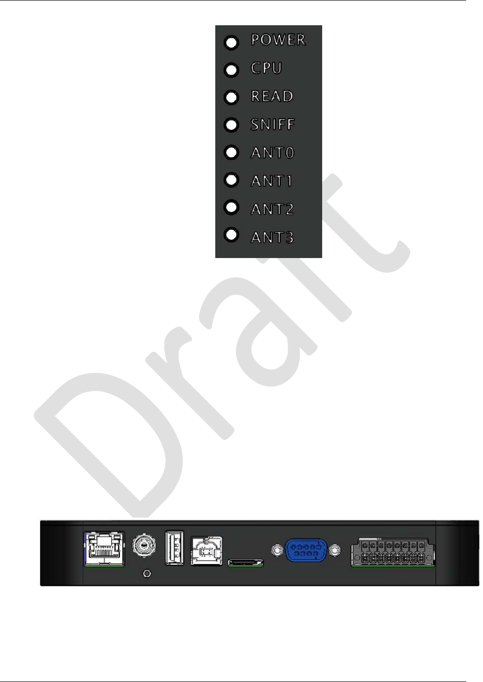
Diagnostic LEDs
The ALR-F800 includes diagnostic LEDs on the face of the reader to provide
easy and convenient external indication for various operating conditions:
On the Front Panel you will find:
POWER (green) – indicates power is applied to the reader.
CPU (green) – indicates CPU is active. (red) – indicates a fault
condition with the reader
READ (green) – indicates that the reader is receiving data from a tag.
Sniff (green) – indicates a tag signal has been detected, though it may
not be strong enough yet to complete a transaction.
Antenna Lights 0-3 (green) – indicates Active transmitting antenna.
CHAPTER 2 READER HARDWARE INSTALLATION AND OPERATION
ALR-F800 HARDWARE SETUP GUIDE
DOC. CONTROL #8102141-000 REV A 12
Figure 7 – ALR-F800 Front Panel Reader Diagnostic LEDs
Reader Antennas
The ALR-F800 includes 4 antenna ports. These antenna ports are a reverse-
polarity TNC connector. Only antennas documented in this manual (FCC
approved) may be used with the ALR-F800.
System Assembly and Bench Test
Assembling the RFID Reader system is easy. We recommend you set up the
system and verify its operation in a bench test configuration before installing it in
a production setting.
Bench Test Configuration
1. Place the Reader on a tabletop. Ensure that a standard 120 or 220 VAC
outlet or 802.3af compliant network port is nearby, and there is sufficient
space is available on the tabletop for the reader and antenna.
Figure 8 – Power, RS-232, USB, SDCard and LAN Connections

CHAPTER 2 READER HARDWARE INSTALLATION AND OPERATION
ALR-F800 HARDWARE SETUP GUIDE
DOC. CONTROL #8102141-000 REV A 13
2. Connect the RS-232 cable or USB B to the reader.
Align the male cable connector so that its shape and pins match the
shape and holes of the female DB-9 RS-232 port.
Figure 9 - RS-232 Connector
Push the aligned connector into the port.
Finger-tighten the screws to secure the cable/connector to the reader.
3. Connect the RS-232 cable to the serial port on the PC.
Settings for RS-232 are 115,200 baud, 8 data bits, no parity, 1 stop bit,
and no flow control.
Start up terminal software on the PC, such as HyperTerminal with these
settings, and be prepared to observe the reader's messages as it boots
up.
4. Connect the POE power supply to the reader.
If you are using an 802.3af compliant network, skip this step.
WARNING: You must use the PoE power supply certified for use with the
ALR-F800 by Alien Technology. Failure to do so voids the product
warranty and violates the terms of the FCC license.
If you are using the PoE power supply, use the standard Ethernet cable
to connect the reader RJ-45 jack to the “LAN+DC” RJ-45 jack of the
power supply.
If you are using the optional DC power cord, connect the DC power jack
into the DC power plug of the reader. Tighten the screw fitting finger
tight.
DO NOT plug the AC power or the DC cord into the supply at this time.
5. Connect the Ethernet cable to the reader and LAN or PC.
If you are using an 802.3af compliant network to power the reader skip
this step.
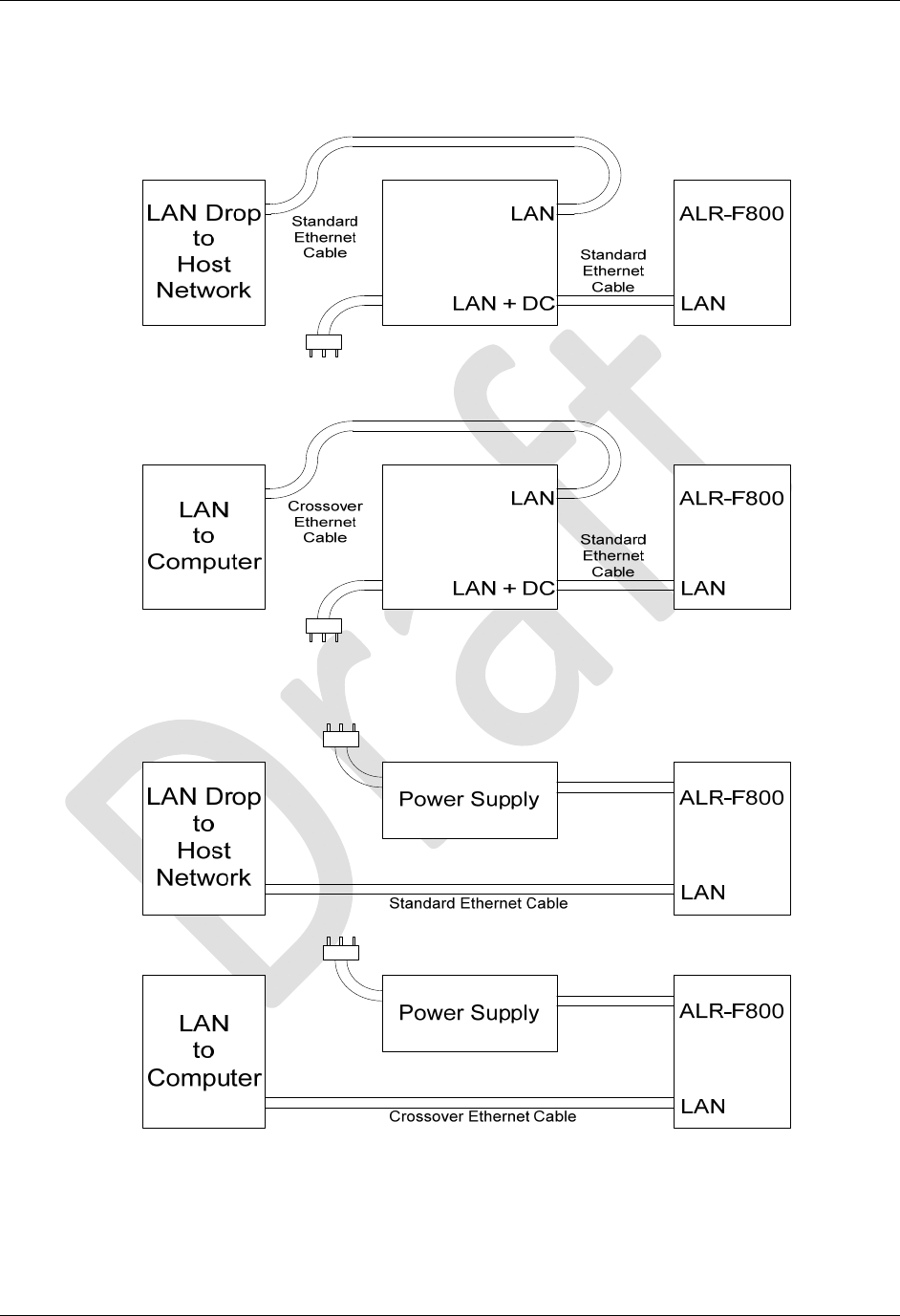
Connecting to the LAN
If you are using the PoE power supply provided with the Reader Kit,
connect a standard Ethernet cable from the PoE power supply LAN
port to a nearby LAN drop or network switch.
If you are using the DC power cord, connect a standard Ethernet
cable to the ALR-F800 LAN/PoE port and to the LAN drop or network
switch.
Connecting directly to a PC
If you are using the PoE power supply provided with the Reader Kit,
connect a cross-over Ethernet cable from the PoE power supply LAN
port to the PC LAN port.
CHAPTER 2 READER HARDWARE INSTALLATION AND OPERATION
ALR-F800 HARDWARE SETUP GUIDE
DOC. CONTROL #8102141-000 REV A 14
If you are using the AC/DC power brick, connect a cross-over
Ethernet cable to the ALR-F800 LAN/PoE port and to the PC LAN
port.
Figure 10 – PoE Power Supply and Network Connection Diagram
Figure 11 – 12V DC cord and Network Connection Diagram
The reader comes preconfigured to look for a DHCP server to set its
network parameters. In the absence of a DHCP server, the reader will
use the following settings:
CHAPTER 2 READER HARDWARE INSTALLATION AND OPERATION
ALR-F800 HARDWARE SETUP GUIDE
DOC. CONTROL #8102141-000 REV A 15
IP Address: 192.168.1.100
Subnet Mask: 255.255.255.0
Gateway: 192.168.1.1
6. Connect the antenna to the antenna port.
The ALR-F800 is a mono-static system (a single antenna acts as both
transmitter and receiver). Four antenna ports (ANT 0-3) are provided.
Each antenna provides a single read point.
Only the antennas listed in this manual and their associated cables (if
specified) may be used with this reader.
The antenna ports are found on the reader I/O panel on the left hand
side if viewing the reader from the top with the connectors at the bottom.
It uses a reverse polarity TNC connector. If using the Alien Gateway
software, please note that ANT 0 is selected by default when first
initialized.
Align the antenna’s coax cable’s center pin and push it into the port.
Screw the fitting from the cable end onto the reader connector clockwise
until finger-tight to secure the cable to the reader.
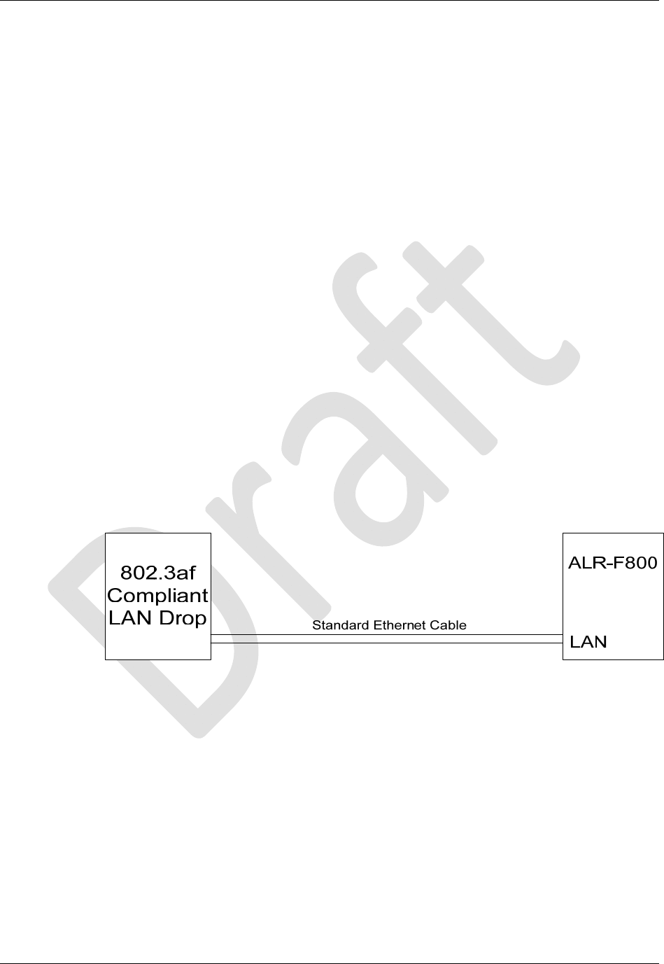
7. Power up the reader
If you are using an 802.3af compliant network to power the ALR-F800
connect a standard LAN cable between the ALR-F800 LAN/PoE port and
the 802.3af enabled LAN drop or network switch. The green POWER
LED will illuminate when power is on.
Note: If using an 802.3af compliant network it must be capable of
supplying up to 12.95 watts.
Figure 12 – 802.3af Network Connection Diagram
If you are using the PoE Power supply or the DC cord, plug the AC
power cord into the supply and into the wall outlet. The green POWER
LED will illuminate when power is on.
8 Observe the reader's boot-up trace on the serial port, and determine the
network settings.
The RS-232 port displays useful information while the reader boots, including
network settings. Toward the end of the trace, the reader displays a block of
text similar to the following:

CHAPTER 2 READER HARDWARE INSTALLATION AND OPERATION
ALR-F800 HARDWARE SETUP GUIDE
DOC. CONTROL #8102141-000 REV A 16
---------------------------------------------
Network Settings:
MAC Address : 00:80:66:10:2D:12
DHCP : 1
IP Address : 10.9.8.10
Netmask : 255.255.255.0
Gateway : 10.9.8.2
DNS : 10.9.8.1
TimeServer : time-a.timefreq.bldrdoc.gov
TimeZone : -7
---------------------------------------------
Once the reader boots and you see the "Boot>Ready!" prompt, pressing
return will bring up the "Alien>" prompt.
9. Ensure the PC has compatible network settings.
In order for you to be able to connect to the reader over TCP/IP, the host
PC must be on the same subnet as the reader. If you are unfamiliar with
how to do this, consult your local IT service for assistance.
Once the initial connection is made, you may configure your reader's
network settings as you choose. Refer to the Reader Interface Guide for
instructions on how to do this.
You are now ready to bench test or demonstrate the RFID Reader system.
Bench Test Procedure
1. Position the reader so you can see the diagnostic LEDs
You may also want to position the PC so you can view the monitor
2. Access an operational mode suitable for bench testing.
Open the Alien Gateway RFID Demonstration Application.
Select Tag Grid on Gateway.
The RF ON light should illuminate.
Refer to the applicable software application user guide for specific
instructions.
3. Move a tag slowly away from the antenna’s range.
Begin with the tag well inside the expected read range (~2m or 6 ft) and
move it toward the antenna while observing the LEDs.
4. Verify the READ LED illuminates when the tag is inside the read zone.
The READ LED should illuminate green.
5. Verify the host receives the tag data.
The tag should be displayed on the monitor.
6. If bench test conditions are verified, proceed to installation.
Installation
This section provides guidance for configuring components in your RFID system.
You should consider the overall design of your specific system before
permanently mounting the equipment.

CHAPTER 2 READER HARDWARE INSTALLATION AND OPERATION
ALR-F800 HARDWARE SETUP GUIDE
DOC. CONTROL #8102141-000 REV A 17
Installation involves many of the same connection steps required for bench test.
However, instead of placing equipment on a tabletop, the reader, antenna, and
their accessories are mounted in your application environment.
Requirements
Before installing your RFID Reader system, you will need the following:
An 802.3af compliant network connection or standard 120 or 220 VAC
power outlet
WARNING: If you do not use an 802.3af compliant network to supply
DC power you must use the power supplies provided by Alien
Technology. Failure to do so voids the product warranty and violates the
terms of the FCC license.
RS-232 cables, Ethernet cables or antenna coax cables needed to
accommodate routing requirements.
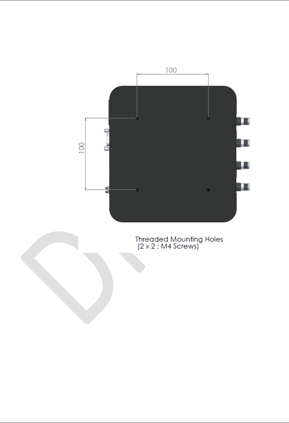
Mounting hardware suitable for the surface to which equipment is to be
attached. Use M4 pan head screws 4.5mm maximum thread length.
Hardware Installation Procedure
1. Select mounting position for antenna(s).
CAUTION: Reader antenna should be positioned so that personnel in
the area for prolonged periods may safely remain at least 23 cm (9 in) in
an uncontrolled environment from the antenna’s surface. See FCC OET
Bulletin 56 “Hazards of radio frequency and electromagnetic fields” and
Bulletin 65 “Human exposure to radio frequency electromagnetic
fields.”
Mount the reader and antenna(s) at the periphery of the desired read
window so that the position of the most distant tag passing through the
window is no farther from the antenna than the maximum range specified
for your system design.
Position the reader and antenna(s) at a height approximately midway
between the highest and lowest expected tag position. (For example, a
pallet tag may be the lowest tag position to be read, while the top-most
case on a fully stacked pallet may represent your highest tag position.)
NOTE: To maintain compliance with FCC regulations, use only
antennas, cables, and power supplies supplied with the unit or approved
by Alien Technology for use with the ALR-F800.
2. Select mounting position for reader.
The ALR-F800 has been designed to provide reliable operation over its
operating temperature range. This is enhanced by proper mounting of the
reader during bench test and installation. Place the reader on a solid,
thermally conductive surface. Optimum thermal performance is achieved by
mounting the unit to a metal mounting plate with direct contact between the
reader base and the mounting plate. When mounting vertically the reader IO
panel should be oriented at the bottom.
Antennas should be placed close enough to the reader to accommodate
the cable length without putting strain on the connectors.
CHAPTER 2 READER HARDWARE INSTALLATION AND OPERATION
ALR-F800 HARDWARE SETUP GUIDE
DOC. CONTROL #8102141-000 REV A 18
Mount units individually. Do not stack them.
3. Install the reader.
Secure the reader through the four mounting holes to its mounting
location (wall, post, mounting bracket) using appropriate M4 pan head
screws less than 4.5 mm long.
4. Install the antenna(s).
Secure the antenna through the mounting holes on either flange to its
mounting location using appropriate hardware.
5. Connect the antenna(s) to reader.
Route coax cable from the antenna to the reader according to your
system design specifications and secure it properly. Do not kink the
antenna cable and maintain bend radii of at least 1 inch.
Align the connector of the cable with the reader antenna port, push into
the port, and finger-tighten the screw fitting.
6. Connect reader power supply.
If you are using an 802.3af compliant network for reader power skip this
step
If you are using the PoE power supply, use a short standard Ethernet
cable to connect the reader’s RJ-45 jack to the LAN+DC RJ-45 jack of
the power supply. Align the RJ-45 connector with the corresponding
TCP/IP port on the reader or the power supply and push the connector
in.

CHAPTER 2 READER HARDWARE INSTALLATION AND OPERATION
ALR-F800 HARDWARE SETUP GUIDE
DOC. CONTROL #8102141-000 REV A 19
If you are using the optional DC power cord, connect the DC power jack
into the DC power plug of the reader. Tighten the screw fitting finger
tight.
DO NOT plug the AC power cord into the supply at this time.
7. Connect reader to the LAN or host PC.
If you are using an 802.3af compliant network for reader power skip this
step.
If you are using the PoE power supply, connect the Ethernet cable into
the LAN jack of the power supply. Align the RJ-45 connector with the
corresponding TCP/IP port on the power supply and push the connector
in. Connect the other end to a LAN drop or network switch. You may
optionally connect the reader directly to a PC's network port, but you
should use an Ethernet cross-over cable in this situation.
If you are using the DC power cord, connect the Ethernet cable into the
LAN jack of the reader. Align the RJ-45 connector with the corresponding
TCP/IP port on the reader and push the connector in. Connect the other
end to a LAN drop or network switch. You may optionally connect the
reader directly to a PC's network port, but you should use an Ethernet
cross-over cable in this situation.
If you wish to observe the reader's boot up trace, or control the reader
via RS-232, align and connect a DB-9 serial cable to the reader's RS-232
port, and to the serial port on the PC. Configure your terminal software
as described previously in the Bench Test Configuration section.
8. Connect reader power.
If you are using an 802.3af compliant network to power the ALR-F800,
connect a standard LAN cable between the ALR-F800 LAN/PoE port and
the 802.3af enable LAN drop or network switch. The green POWER LED
will illuminate when power is on
Note: If using an 802.3af compliant network it must be capable of
supplying up to 12.95 watts.
If you are using the PoE power supply or the DC cord, plug the AC
power cord into the supply and into the wall outlet. The green POWER
LED will illuminate when power is on.
9. You are now ready to use the reader.
System Operation: Software Control
The ALR-F800 RFID Reader is controlled from software running on a host
system that communicates with the reader using the ASCII-based Alien Reader
Protocol. All applications use this protocol to communicate with the reader.
You may operate the reader from your own application code, using the example
code provided on the Developer’s Kit download, or using the Alien RFID
Gateway application which is a demonstration program also included in your
download instructions.
For more details, refer to either the Reader Interface Guide or the Demonstration
Software Guide described briefly below.

CHAPTER 2 READER HARDWARE INSTALLATION AND OPERATION
ALR-F800 HARDWARE SETUP GUIDE
DOC. CONTROL #8102141-000 REV A 20
Reader Interface Guide
The Alien Reader Protocol, mentioned previously, is described in detail in the
Reader Interface Guide. Using this interface, the reader can be configured to
read tags when queried or after one of a variety of event triggers (e.g., a rising
edge on one of the I/O pins or a timer).
Tag data acquired in response to these triggers can be transmitted to the host in
a number of formats (e.g., text, XML or custom) and under a number of
conditions (e.g., on a new tag being observed, or a tag disappearing from view).
If you are a software developer, the Reader Interface Guide provides the
information you will need to connect to the reader from a host computer,
communicate with it, and customize its performance.
Demonstration Software Guide
The Demonstration Software Guide describes the installation and operation of
the Alien RFID Gateway application.
The Alien RFID Gateway application is a useful demonstration program that
allows users to explore the reader’s functionality and build customizable demos
with a user-friendly interface.
Using the Gateway, the various operating modes of the reader can be controlled
and custom interactive demos can be constructed using sounds, images, and
text.
Alien RFID Academy
Need to absorb RFID systems fast? Enroll in the Alien RFID Academy! In two or
three days we'll share our practical expertise in RFID tags, antennas, readers,
frequencies, systems, and protocols.
The Alien RFID Academy is a hands-on immersion into the workings, uses, and
challenges of RFID technology. Rather than a product pitch, we put products to
the test in the classroom, provide students with hands-on exposure in our RFID
Solutions Center, and short-cut the learning curve by sharing practical solutions
to real-world challenges. You'll learn best industry practice tag placement
techniques for packaging and pallets alike.
Upon completion of the training, you will learn how to avoid common costly
mistakes, know how to make the correct decisions for your business, how to
select the right RFID options for your requirements, and where to find RFID
answers.
Alien RFID Intermediate / Advanced Academy Topics:
• RFID Physics, Protocols & Practical Applications
• Tag Placement & Packaging Considerations
• RFID Reader/System Configuration & Optimization
• Hands-on Implementation
• RFID System Architecture and Integration
• Conducting Site-surveys & Contending with Interference
Please visit http://www.alientechnology.com for more information.