Alltek Marine Electronics AIS-B600W AIS Class B Transponder (SOTDMA) User Manual users manual
Alltek Marine Electronics Corporation AIS Class B Transponder (SOTDMA) users manual
Contents
- 1. users manual
- 2. Annex to users manual
users manual
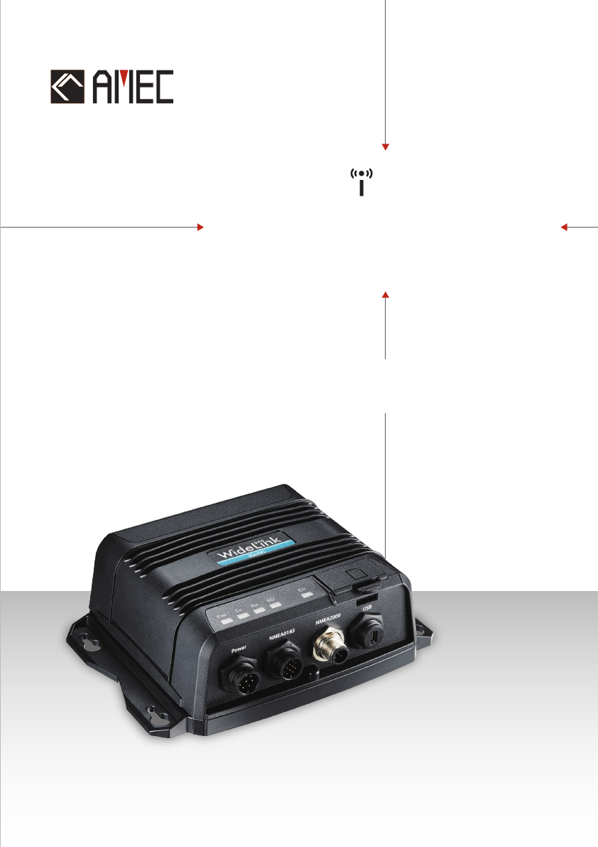
USER MANUAL
AIS Class B Transponder
WideLink B600
SOTDMA
( )

3
COPYRIGHT
The entire contents of this instruction manual, including any future updates, revisions,
and modifications, shall remain the property of AMEC at all times. Unauthorized
copies or reproduction of this manual, either in part or whole, in any form of print and
electronic media, is prohibited. The contents herein can only be used for the intended
purpose of this manual.
DISCLAIMER
AMEC is devoted to publish and maintain this product manual. As we continue to
improve our AIS products to satisfy all customers’ needs, information in this
document is subject to change without notice. AMEC does not make any
representations or warranties (implied or otherwise) regarding the accuracy and
completeness of this document and shall in no event be liable for any loss of profit or
any commercial damage, including but not limited to special, incidental,
consequential, or other damage.
Manual Revision: Version 1.0
User’s Manual

4
WARNING!
WARNING: The device must be installed and configured in conformity with the
provided instructions in the manual by qualified installer in order to ensure the
device performance.
WARNING: It is the responsibility of the operator to handle the AIS device with
care. The device cannot replace human vigilance. Therefore it is important to
keep a diligent outlook at all times.
WARNING: Please bear in mind that not all vessels are equipped with AIS
transponders and therefore may not be visible to this device. Likewise, certain
conditions, such as device malfunction, the environment, improper use, and
overcrowded port traffic, may exist whereby the vessel equipped with this AIS
device is not visible to other AIS transponders.
WARNING: DO NOT DISASSEMBLE OR MODIFY THE EQUIPMENT. Improper
disassembly or modification could impair its performance and will invalidate the
guarantee.
FOR USERS IN THE UNITED STATES OF AMERICA ONLY
WARNING: It is a violation of the rules of the Federal Communications
Commission to input an MMSI that has not been properly assigned to the
end user, or to otherwise input any inaccurate data in this device.
★ The entry of static data into this device shall be performed by the vendor of
the device or by an appropriately qualified person in the business of installing
marine communications equipment on board vessels.
★ Instructions on how to accurately enter and confirm static data in the device
can be found in this user manual.
FOREWORD
We thank you for the purchase of your new WideLink B600, AIS SOTDMA class B
transponder. Wherever you sail now, you can have a better overview of your
surroundings at sea and voyage with more safety.
WideLink B600 is strictly tested to meet the rigorous demands of the marine
environment. With proper installation and use, the equipment will serve loyally and
reliably at its optimum.
For sales, services, and technical supports, please contact your local AMEC
representatives or Alltek Marine Electronics Corp at sales@alltekmarine.com or
service@alltekmarine.com. You are always welcome to visit our website at
www.alltekmarine.com for new product status and company update.
Thank you again. Be safe.

5
TABLE OF CONTENT
1 SYSTEM OVERVIEW ........................................................................................................................ 6
1.1 PRODUCT DESCRIPTION ......................................................................................................... 6
1.2 CLASS A VS. SOTDMA CLASS B VS. CSTDMA CLASS B ............................................................... 8
1.3 EQUIPMENT IN THE BOX ......................................................................................................... 9
2 INSTALLATION .................................................................................................................................. 10
2.1 INSTALLATION PROCEDURES .................................................................................................. 10
2.2 MOUNTING DEVICE MAIN UNIT ............................................................................................ 11
2.3 VHF ANTENNA INSTALLATION ............................................................................................... 12
2.4 GPS ANTENNA INSTALLATION................................................................................................ 13
2.5 CONNECTING WITH NMEA 0183 DEVICES .............................................................................. 14
2.6 AIS SILENT MODE CONNECTION ............................................................................................ 15
2.7 CONNECTION TO NMEA 2000 NETWORK ............................................................................... 16
2.8 CONNECTING POWER CABLE ................................................................................................. 17
2.8.1 Alarm Relay ..................................................................................................................... 18
3 CONFIGURING YOUR WIDELINK B600 .................................................................................... 19
3.1 ESTABLISH CONNECTION TO PC.............................................................................................. 19
3.1.1 USB Driver Installation .................................................................................................... 19
3.1.2 Serial Port Connection .................................................................................................... 20
3.1.3 Wireless Connection (only for WideLink B600W) ........................................................... 20
3.2 PROGRAMMING YOUR VESSEL DATA ......................................................................................... 21
4 GET STARTED .................................................................................................................................... 22
4.1 LED INDICATORS ................................................................................................................ 22
4.2 MICRO SD CARD DATA LOGGING ........................................................................................... 23
4.3 WI-FI CONFIGURATION (WIDELINK B600W ONLY) ................................................................... 24
4.3.1 Access Point Mode ......................................................................................................... 24
4.3.2 Client Mode .................................................................................................................... 26
4.4 BUILT-IN INTEGRITY TEST (BIIT)............................................................................................. 27
4.5 AIS VIEWER DESCRIPTION .................................................................................................... 27
4.6 INTRODUCING AMEC AIS APP ............................................................................................. 28
5 SPECIFICATIONS .............................................................................................................................. 29
5.1 PRODUCT SPECIFICATIONS .................................................................................................... 29
5.2 DIMENSIONS ..................................................................................................................... 31
5.3 NMEA 2000 PGN INFORMATION ........................................................................................ 32
5.4 SUPPORTED NMEA 0183 SENTENCES .................................................................................... 33
6 TROUBLESHOOTING ...................................................................................................................... 34
7 ABBREVIATIONS .............................................................................................................................. 36
8 FCC INTERFERENCE STATEMENT .............................................................................................. 37
9 RF EXPOSURE WARNING .............................................................................................................. 38
DECLARATION OF CONFORMITY ........................................................................................................ 38
AMEC WORLDWIDE WARRANTY ........................................................................................................ 39
APPENDIX: HOW TO DETERMINE SERIAL PORT .......................................................................... 40
6
1 System Overview
1.1 Product Description
WideLink B600 is an SOTDMA AIS class B, the next evolution of AIS technology. Its 5W
transmit power, higher reporting rate and professional grade time division
management make B600 an overall more advanced product compared to AIS class B
based on CSTDMA scheme.
The globally approved device contains 1 VHF transmitter, 2 AIS receivers on 2 VHF
channels and 1 MCU with cutting edge software defined radio technology. Its internal
GNSS receiver with 50 channels is able to process signals from GPS, Gallieo, BeiDou
and GLONASS with differential capability. It receives DSC, time-sharing with AIS
receivers.
Its enhanced housing with IPx7 waterproof and shock and temperature robustness is
ideal to survive harsh marine environments. Chart plotter and PC can be easily
integrated over its NMEA2000, NMEA0183 and waterproof USB port. Its built-in data
logger can record AIS data on micro SD card in the most intuitive way.
The integrated high performance Wi-Fi (WideLink B600W only) together with AMEC
AIS App makes your favorite smart phone or tablet a real-time AIS position plotter.
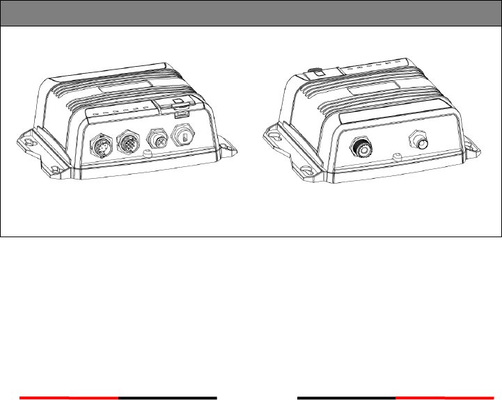
WideLink B600
Front Back
B600 exchanges the following navigational data with other AIS equipped vessels within
VHF range to increase the safety of your journey at sea:
Static data:
Ship´s name
Call sign
MMSI
Ship type

7
Location of GPS antenna on the ship
Dynamic data:
Position of the vessel
Course over ground (COG)
Speed over ground (SOG)
True heading
It receives also safety related messages (SRM) from other vessels or persons who are in
distress.
SOTDMA Class B AIS broadcasts ship´s static data every 6 minutes. Ship dynamic data
will be transmitted per following reporting interval:
Ship Speed
Nominal Reporting Interval
Increased reporting interval
>23 knots
Every 5 seconds
Every 15 seconds
between 14-23 knots
Every 15 seconds
Every 30 seconds
between 2-14 knots
Every 30 seconds
Every 30 seconds
≤ 2 knots or at anchored or
moored
Every 3 minutes
Every 3 minutes
The Class B “SO” AIS follows the rules set by ITU-R M.1371-5, and increases the
reporting interval to “Increased Reporting Interval” in accordance with Table above
when less than 50 % of the slots of each of the last four consecutive frames are free.
When more than 65 % of the slots of each of the last four consecutive frames are free,
the Class B “SO” AIS reports at the “Nominal Reporting Interval”.

8
1.2 Class A vs. SOTDMA Class B vs. CSTDMA Class B
A brief comparison between class A and class B AIS is illustrated in the following table.
WideLink B600 is an SOTDMA class B AIS transponder.
Type of AIS
Class A AIS
Class B SOTDMA
Class B CSTDMA
Primary Access
Scheme
SOTDMA
(Self-organizing)
SOTDMA
(Self-organizing)
CSTDMA
(Carrier-Sense)
Standard
IEC 61993-2
IEC 62287-2
IEC 62287-1
Transmit Power
and range
12.5W
5W
2W
IMO Mandate
Mandatory for all
SOLAS vessels
No mandate
No mandate
Reporting rate
dynamic data
Highest (transmission
up to every 2 sec)
Higher (transmission
up to every 5 sec)
Low (transmission up
to every 30 sec)
AIS data
presented
Static, Dynamic,
Voyage
Static and Dynamic
data
Static and Dynamic
data
Applications
Commercial vessels,
fishing boats, working
boats, passenger
boats with more than
12 passengers
Smaller commercial,
fishing and work
boats, recreational
vessels
Recreational vessels
and small fishing
boats
9
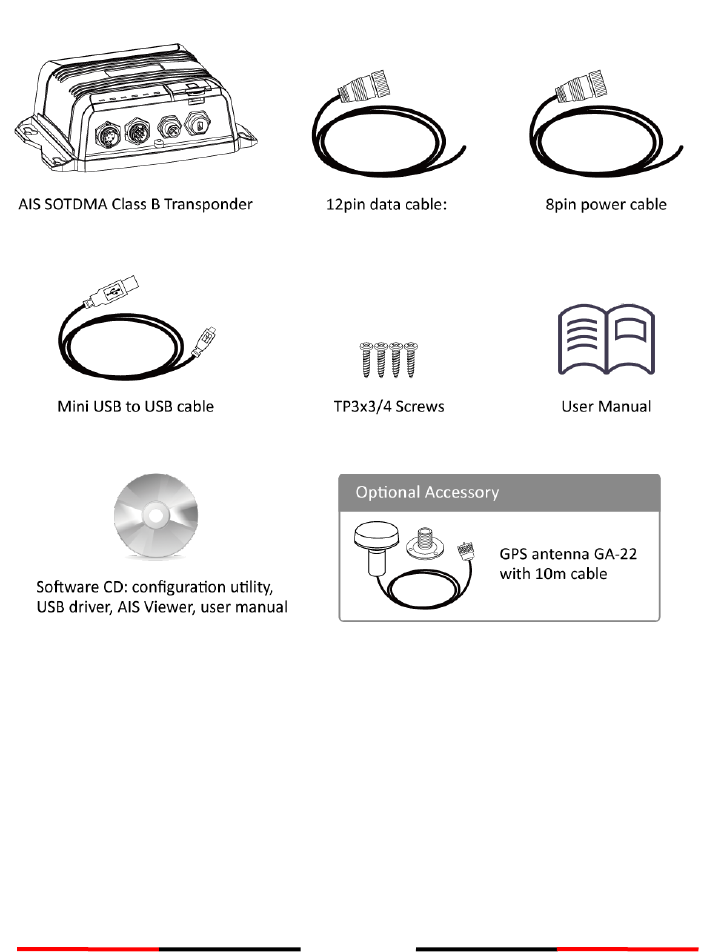
1.3 Equipment in the Box
Upon receiving the product please verify items in the box. If any is missing, please
contact your local AMEC representative immediately.
10
2 Installation
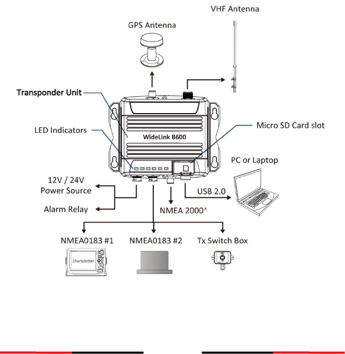
2.1 Installation Procedures
Please familiarize the manual content before installation. Depending on your
hardware configuration, use the following recommended steps to install the device.
1) Mount the device unit to an appropriate location
2) Install VHF antenna
3) Install GPS antenna
4) Connect to a chart plotter via NMEA 0183 and/or other instruments
5) Connect to a chart plotter via NMEA 2000 and/or other instruments
6) Connect to a Tx switch box and/or external alarm system(optional)
7) Connect to an appropriate power source (12V / 24V DC, 2A)
Figure 1 External Connections
11
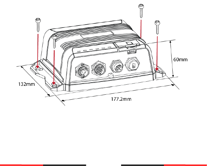
2.2 Mounting Device Main Unit
The following guidelines should be noticed when selecting the environment to install
your AMEC WideLink B600:
Do not install the device in a flammable or hazardous atmosphere such as in an
engine or generator room or close to fuel tanks.
Installation of the device should be undertaken in a safe environment without
being exposed to any splashing water or rain.
There should be adequate space around the device for routing of cables. See figure
below for details of the device dimensions.
The safe distance of the device to any magnetic compass is at least 0.3m.
The operating temperature is between -15°C and +55°C.
The device can be installed and mounted on flat surface, or it can be mounted on
wall with the four self tapping screws supplied.
The device should be mounted in a location where the indicators can readily be
observed as these indicators deliver relevant information on the status of the
device.
Figure 2 Mounting the Device
12
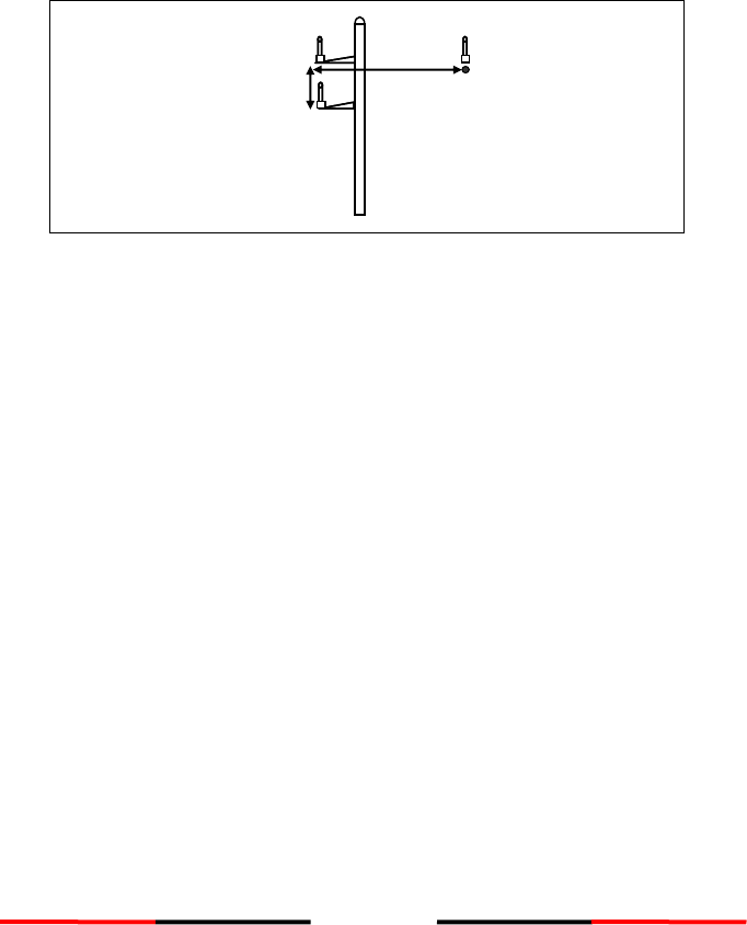
2.3 VHF Antenna Installation
The quality and positioning of the antenna are the most important factors dictating
AIS performance. It is recommended that a VHF antenna with omnidirectional vertical
polarization be specifically tuned for marine band. Since the range of VHF signals is
largely decided by line of sight distance, the VHF antenna should be placed as high as
possible and at least 5 meters away from any constructions made of conductive
materials.
Figure 3 VHF Antenna Locations
The VHF antenna connector type on WideLink B600 is SO239 which is designed to
work with a PL259 connector.
The recommended
horizontal distance
between antennas is 10m.
Other transmitting
antenna
VHF Antenna
2m
10m
Other VHF Antenna
The recommended
vertical distance between
antennas is 2m.
13
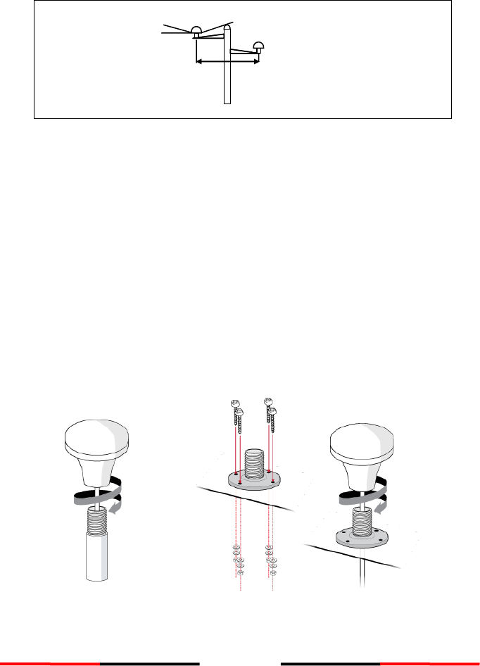
2.4 GPS Antenna Installation
Install the GPS antenna where it has a clear view to the sky, so that it may access the
horizon freely with 360° degrees.
Figure 4 GPS Antenna Locations
It is recommended to keep the GPS antenna out of the transmitting beam of
high-power transmitters such as Inmarsat devices and radar.
When connecting the cables, take note of the following precautions.
Bending cables may cause damages to the inner wires and impair overall the
performances.
Each coaxial cable should be set up separately and can only be set up in a
single cable tube.
Insulation on connector port of the coaxial cable should be considered.
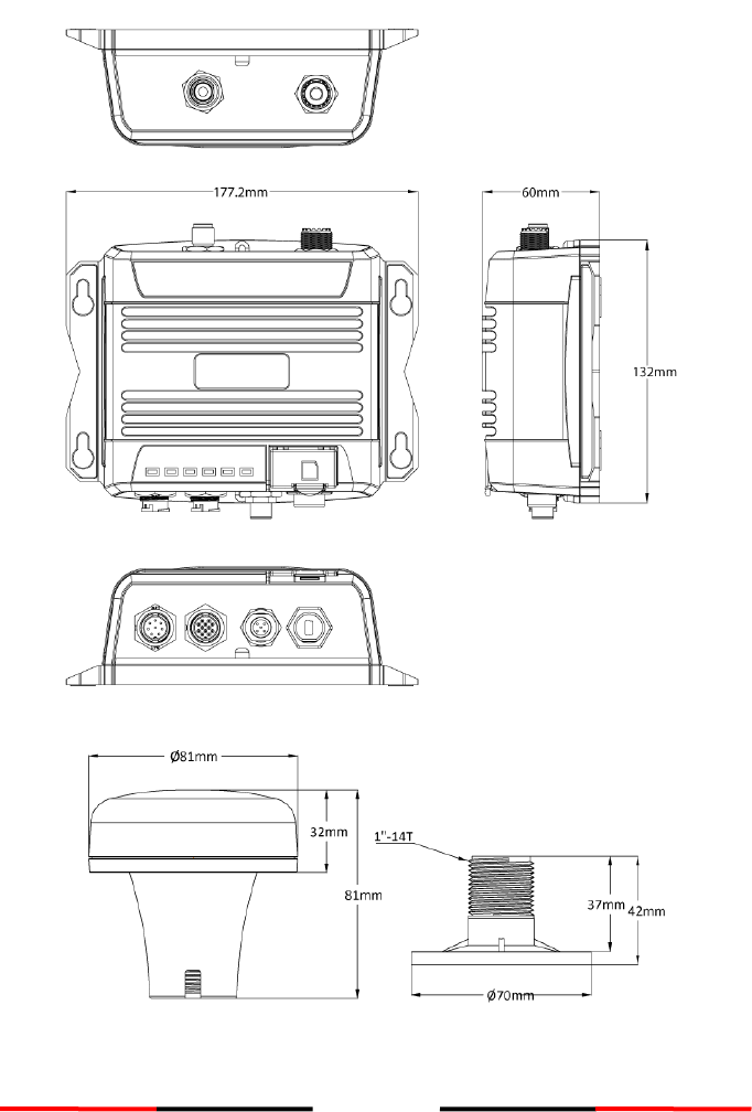
WideLink B600 is tested and certified with the GPS antenna GA-22. It’s recommended
to use GA-22 with B600 series to ensure optimal reliability of your AIS system.
For pole mounting the GA-22, a 1 inch 14 TPI thread pole will be required.
Figure 5 Mounting GPS Antenna
Ensure a free 360˚
horizon with a vertical
observation of 5˚.
The recommended
horizontal distance between
GPS antennas and other
antennas is 3m.
5˚
3m
14
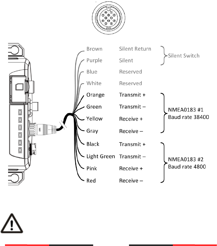
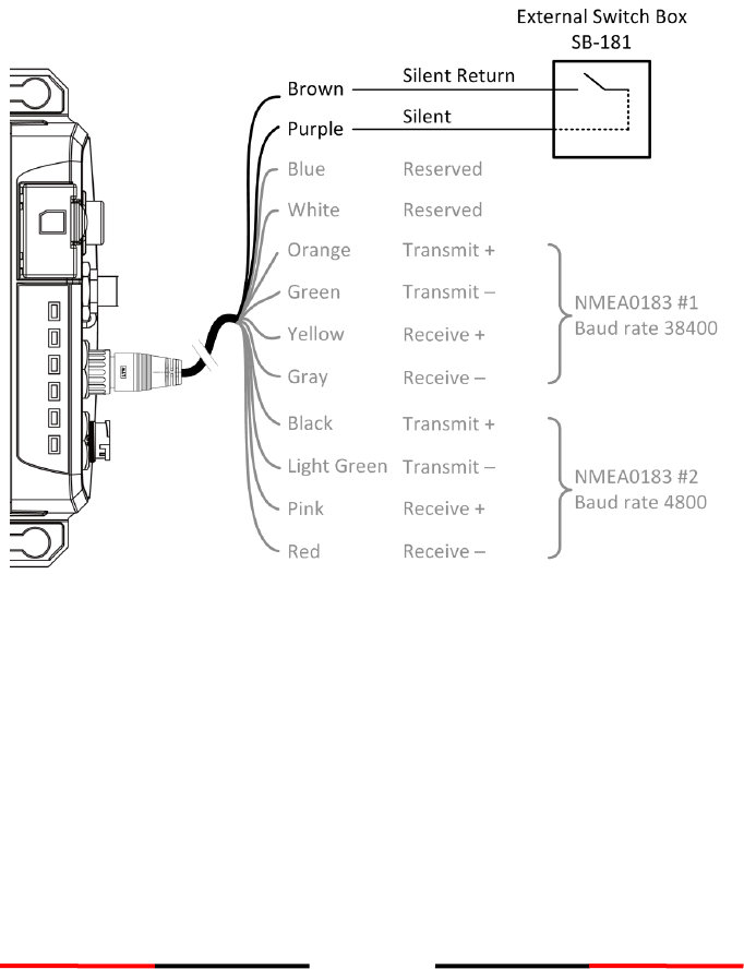
2.5 Connecting with NMEA 0183 Devices
WideLink B600 supports two NMEA 0183 ports and external silent mode switch with
its 12-pin data cable. The default NMEA 0183 baud rates are 38400-bps (high speed)
and 4800-bps (low speed). User can change the baud rates using the provided
configuration utility. Typically the high speed setting is primarily for chart plotter
connection, while the low speed setting can be used for NMEA 0183 compatible
instruments.
WideLink B600 NMEA 0183 supports multiplexer function. Received NMEA 0183 data
from both ports will be multiplexed and forwarded to all output ports as well as USB
and Wi-Fi (B600W only).
Figure 6 NMEA 0183 Connection
Warning: During installation, you may have to peel off some wires to
make the appropriate connections. After completing the installation,
please cover all exposed wires with a rubber-vulcanized tape to prevent
the devices from malfunctioning or short-circuited.
15
2.6 AIS Silent Mode Connection
When Silent Mode is required, it is possible to connect an external toggle switch to
WideLink B600. Connect the toggle switch between the purple and brown wires to
enable Silent Mode function, as depicted in Figure below. An optional Tx Switch Box
(part number SB-181) is available from AMEC for Silent Mode activation.
Figure 7 Silent Switch Connection
16
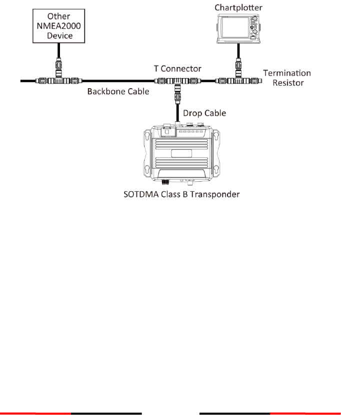
2.7 Connection to NMEA 2000 Network
The WideLink B600 is equipped with NMEA 2000 interface with LEN=1. The device is
able to send AIS data and forward received GPS data (from NMEA 0183) via NMEA
2000 network to other NMEA 2000 devices. For further applications e.g. heading
sensor connection, please refer to supported PGN in 5.3. An updated PGN list is
available at AMEC website under Support/FAQ.
A compatible T-connector and drop cable/spur available by your local service partner
are needed to connect the device to your chart plotter with NMEA 2000 interface:
Figure 8 NMEA 2000 Network
17
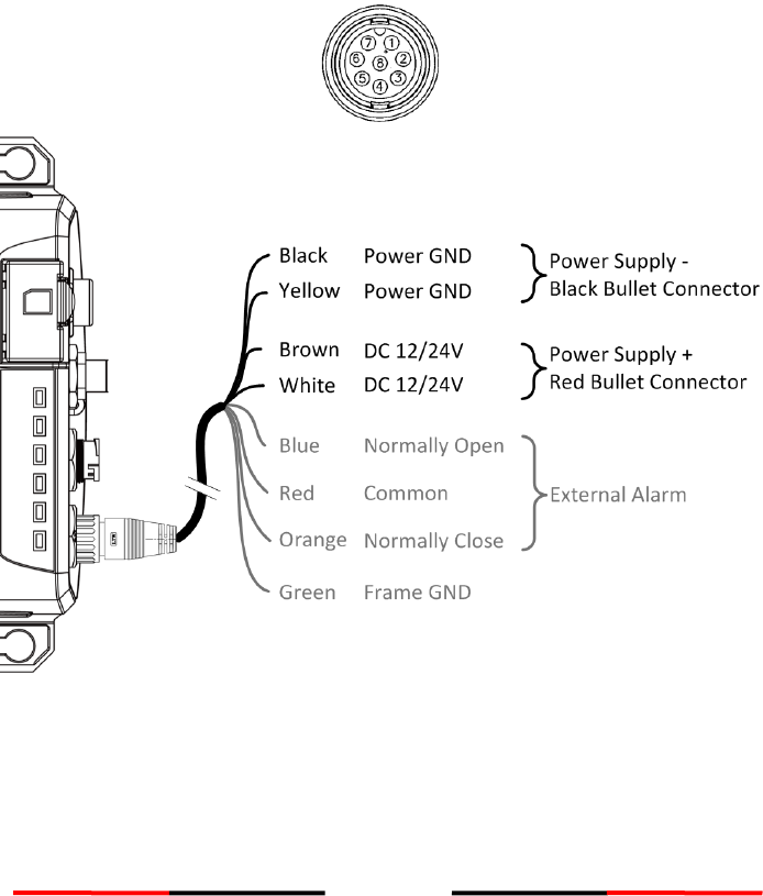
2.8 Connecting Power Cable
Connect the WideLink B600 to vessel´s power source as illustrated below.
The device requires a 12V or 24V DC power supply (9.6 to 31.2V) capable of supplying
2A peak current @12V DC. Always use a minimum 3A fuse panel before connecting
directly to battery or power supply. Power on the power source will turn on the device
unit automatically.
B600´s power cables are marked with bullet connectors.
Figure 9 Power and Alarm Connection

18
2.8.1 Alarm Relay
WideLink B600 supports internal alarm relay with its 8-pin power cable. Connect the
alarm relay to an audible alarm device or the ships alarm system, if available.
The maximum switching current is 1 A.
The maximum switching voltage is 250 VAC, 220 VDC.
Signal
Function
ALARM COM (Red)
Alarm relay common
ALARM NC (Orange)
Alarm relay normally closed
ALARM NO (Blue)
Alarm relay normally open

19
3 Configuring Your WideLink B600
For configuration and firmware upgrade purpose, B600 series can be powered only by
USB. When USB power is in use, the device will not transmit any data. To configure
the Wi-Fi of B600W, user needs a regular 12/24V DC power supply.
The AMEC AIS Class B SO-TDMA Configuration is a powerful tool allowing users to set
up the transponder and make real time diagnosis. A more detailed user guide of
Configuration software can be found in the “Help” of the configuration software.
To install the software, open the AMEC AIS Configuration file on the CD and click on
the setup icon to start the installation process. Follow the on-screen instructions
to complete the installation and check the checkbox to start the AMEC AIS Class B
SO-TDMA Configuration at the end of the installation.
3.1 Establish Connection to PC
3.1.1 USB Driver Installation
Before preceding the configuration procedure, make sure the following items are
available:
Required Items
USB Driver (included in the software CD)
USB cable (included in the box)
PC/Laptop with Windows operating system (not included). WideLink B600 USB
Driver supports Windows XP, Windows Vista, Windows 7, Windows 8/8.1 and
Windows 10
One available USB port on PC
Available CD-ROM drive on PC
The USB driver has to be installed before linking the device to your PC. Power on the
device and connect it to PC with the attached USB cable. A new hardware found
prompt will show up. In most cases the USB driver will be installed automatically by
Windows system.
When USB driver installation is not done automatically, user can also manually install
the USB driver which can be found on the attached CD. Follow the on screen
instructions and assign the correct file path of the USB driver to complete the
installation. You can also install the USB driver via the Device Manager in the Control
Panel.
20
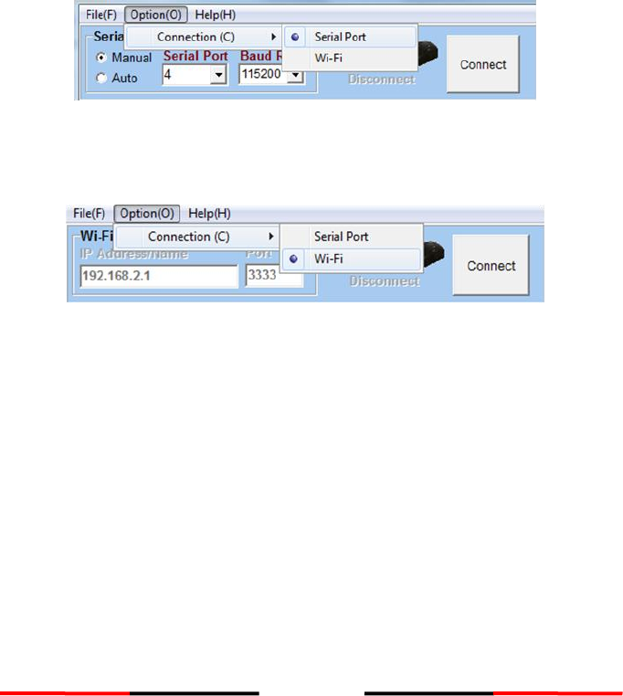
3.1.2 Serial Port Connection
After the USB driver is installed and the device is recognized as a “Virtual Com Port”,
launch the Configuration Software, select Option in the menu bar, then Connection,
and “serial port”. There are 2 options to connect the software with your device:
Auto: The system will scan all connected ports and their available baud rates
and establish connection automatically.
Manual: Configure baud rate and port manually. The default baud rate is
115200. To determine serial port with which the device is connected, please
refer to Appendix in this manual.
Click on “Connect”, to connect the Configuration Software with your device.
Figure 10 Serial Port Connection
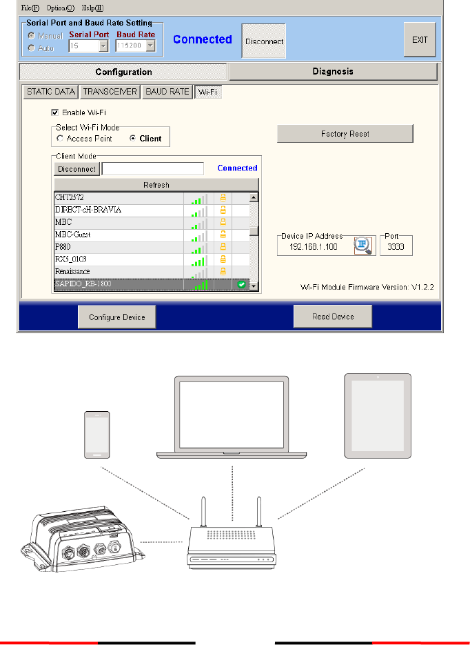
3.1.3 Wireless Connection (only for WideLink B600W)
Figure 11 Wi-Fi Connection for WideLink B600W
For WideLink B600W, the connection between the Configuration Software and the
device can also be established wirelessly. Please refer to 4.4 “Wi-Fi Configuration”
about how to access WideLink B600W from your PC as Access Point.
After your PC is wirelessly connected with the device, go to Option in the menu bar,
then Connection, and “Wi-Fi”. The IP address and Port are already preprogrammed to
fit WideLink B600W´s configuration. Click on “Connect”, to connect the Configuration
Software with your device.
21
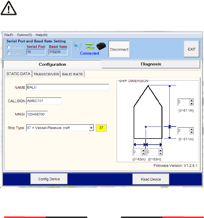
3.2 Programming your vessel data
After the device is successfully connected with the Configuration Software, click on
the “STATIC DATA” tab. You will require the following information in order to configure
the device:
• Vessel´s name: limited to 20 characters
• Call sign: limited to 7 characters
• MMSI: Enter your MMSI (Maritime Mobile Service Identity) number
• Ship type: choose your ship type from the drop down list
• Ship dimensions: Enter the vessel dimensions by appointing position of your GPS
antenna
WARNING: The MMSI number can only be entered
once. Be sure to enter the correct MMSI number, as it
cannot be corrected if entered incorrectly.
Figure 12 Static Data Setting

22
4 GET STARTED
The device starts up whenever the connected power source is ON. It will operate
automatically when the device has been properly configured and GPS/VHF antennas
are properly installed. The device transmits its own ship positions depending on
vessel´s moving speed and should receive information of other vessels in the vicinity.
The operation status of the device can be observed with the LED lights on the unit.
Description of the LED indications is provided in the following section.
4.1 LED Indicators
Indicator
Light
Description
Power
Green, steady
The device has been powered up correctly.
By USB power, the Power LED does not light
showing that the device is in low power mode.
Tx / Silent
Green, flashing
The device is transmitting AIS data. The flashing
interval varies depending on vessel speed.
Orange, steady
The device is in silent mode, no AIS transmission at
all.
Rx
Green, flashing
The device is receiving AIS data.
SD
Green, flashing
SD card is being accessed.
Green, steady
SD card is inaccessible due to malfunction.
Wi-Fi (B600W)
Green, flashing
The green LED indicates an active Wi-Fi traffic
Error
Red, steady
MMSI is not properly programmed
Red, flashing
A BIIT system error is detected referring to chapter
4.4, or by USB power
23
4.2 Micro SD Card Data Logging
The WideLink B600 records voyage data onto a micro SD card in .txt format. The
compatible micro SD card types are listed as follows:
Standard “SD” with maximum 2GB size
Standard “SDHC” with maximum 32GB size
Supported data format: FAT12/16 by SD, FAT32 by SDHC
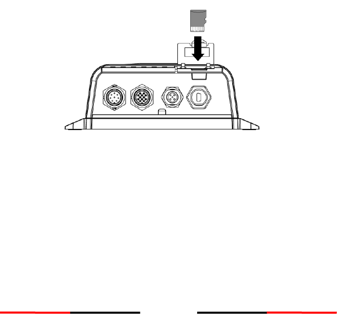
Insert the Micro SD card into the slot as shown below and data logging will start
immediately. When the device begins recording, the green SD LED indicator blinks.
When recorded data gets full, it overwrites new data as deleting from the oldest data.
Removing Micro SD card from the device stops data logging immediately, and the SD
LED will turn off.
The log files have naming convention of AIS_XXXXXX.txt with increment from 000001
to 999999. Entry in the log file is vessel’s GPS sentence in IEC61162 format. The log
file can be read by chart plotting PC software like AMEC AIS Viewer or NaviPro ECS.
Figure 13 Inserting SD Memory Card
24
4.3 Wi-Fi Configuration (WideLink B600W only)
WideLink B600W has high performance Wi-Fi module and antenna built in. It can
work in Access Point Mode or Client Mode.
The information below details the information required for connecting the WideLink
B600W to another device using Wi-Fi.
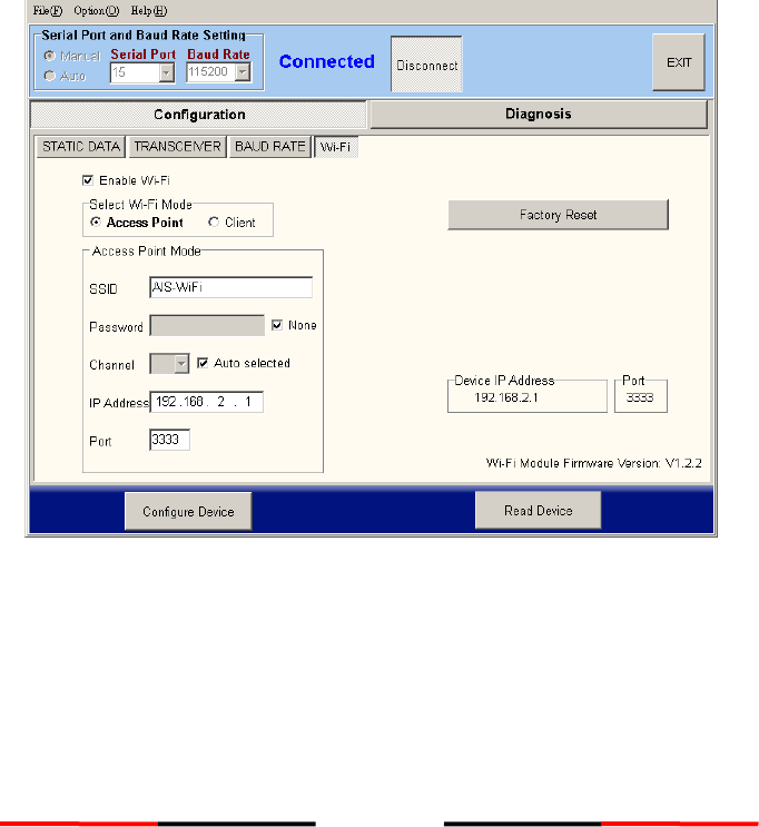
4.3.1 Access Point Mode
WideLink B600W is featured with powerful Wi-Fi performance supporting wireless
connection with up to 32 mobile devices. After the configuration is done, press
“Configure Device” to save the settings to the device.
Figure 14 Access Point Mode
25
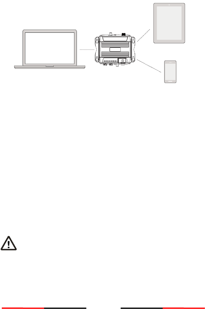
Figure 15 Connect to Mobile Devices
SSID (Service Set Identifier):
The SSID for the WideLink B600W is AIS-WiFi. When user wants to create their
own SSID, just input the preferred SSID in the SSID field and then press
“Configure Device”.
Password:
By default the Wi-Fi network has no password. Users are allowed to create their
own key with an alpha-numeric password between 8 and 63 characters long.
The password can include symbols (!?*&_) and spaces.
System IP:
Default system IP is 192.168.2.1
User can create IP by inputting value in individual field.
Port:
Default port is 3333. User can set the port between 3000-65535.
Note: By default AMEC WideLink B600W uses WPA2-Personal wireless
security protocol.
26
4.3.2 Client Mode
WideLink B600W is able to join an existing Wi-Fi network. When clicking on „Client”, it
can take up to 30 seconds until WideLink B600 scans all available Wi-Fi networks.
Pick the network you want to join and enter the password and click on “Connect”.
Figure 16 Client Mode
Figure 17 Join an Existing Wi-Fi Network
27
4.4 Built-in Integrity Test (BIIT)
With BIIT (Built in Integrity Test) function, the WideLink B600 is constantly monitoring
and testing the integrity of the AIS device. Should an abnormal condition as listed
below be detected, the Error LED will alert:
MMSI not set (Error LED steady on)
Antenna VSWR exceeding the maximum allowed level (Error LED flashing)
Background noise level exceeds allowable threshold (-77dBm) (Error LED flashing)
GPS is unable to gain lock (3D fixed) after 30 minutes of losing GPS signal (Error
LED flashing)
Unusual power input (9V or >36V DC) or by USB power (Error LED flashing)
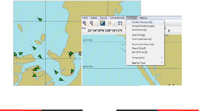
4.5 AIS Viewer Description
The AIS Viewer is a complementary charting software supplied with your WideLink
B600 purchase. The software installation file and its user manual can be found in the
provided CD-ROM.
This powerful tool allows users to display AIS targets either on a basic line map or in
an alphanumeric view. It transforms your PC to a user-friendly AIS data logger and can
trace other vessels with voyage track. Besides, the software offers various safety
features to help users be alerted during their voyage.
Once the program is installed, you can establish a connection to PC either
automatically or manually by assigning the COM port and baud rate. Please notice
that before trying to connect to PC, you should quit the Configuration Software or
vice-versa. The device can only establish connection to one software at a time. The
AIS CPA/TCPA setting can be configured via AIS Viewer.
Figure 18 AMEC AIS Viewer

28
4.6 Introducing AMEC AIS App
The AMEC AIS App is a complimentary App with the purchase of an AMEC AIS
WideLink B600W. The App enables users to monitor the surrounding AIS traffics on
your smart phone or tablet PC wirelessly.
The AIS targets are displayed clearly in radar view or in an alphanumeric vessel list
format. Data of own vessel can be traced in real time. The App also offers various
safety features to help users be alerted during their voyage.
The AMEC AIS App is now available on Apple App Store for iOS devices as well as on
Google Play for Android mobile devices.
Legal
Apple, the Apple logo, iPhone, iPad, iTunes, and iOS are trademarks of Apple Inc., registered in
the U.S. and other countries. iTunes Store is a service mark of Apple Inc., registered in the U.S.
and other countries. App Store are trademarks of Apple Inc.
Google, the Google logo, Android, and Google play are trademarks of Google Inc., registered in
the U.S. and other countries.

29
5 SPECIFICATIONS
5.1 Product Specifications
APPLICABLE STANDARDS
ISO MSC. 74(69) Annex
ITU-R M. 825-3:1998
ITU-R M. 1084-5:2012
ITU-R M. 1371-5:2014
EN 300 440 V2.1.1 (Final Draft)
EN 301 489-1 V2.1.0(Draft) / EN 301 489-3 V2.1.0(Draft)
EN 301 489-1 V2.1.0(Draft) / EN 301 489-17 V3.1.0(Draft)
EN 60950-1:2006 + A11:2009 + A1:2010 + A12:2011 + A2:2013
IEC 60945 Ed. 4.0:2002
IEC 61108-1 Ed. 2.0:2003
IEC61162-1 Ed. 5.0:2016
IEC61162-2 Ed. 1.0:1998
IEC 62287-2 Ed. 2.0:2017
EN 300 328 V2.1.1
EN 62311:2008
VHF TRANSPONDER
Frequency Range
156.025 MHz ~ 162.025 MHz
Access Scheme
SOTDMA
Channel Bandwidth
25 KHz
Modulation
GMSK / FM
Data Rate
9,600 bps
Number of AIS Transmitter
1
Number of AIS Receiver
2 (one time-shared between AIS and DSC)
Number of DSC Receiver
1 (time-shared between AIS and DSC)
AIS Channel 1
CH 87B (161.975 MHz)
AIS Channel 2
CH 88B (162.025 MHz)
Tx Power Output
5 Watt (37 dBm ± 1.5 dB)
1 Watt (30 dBm ± 1.5 dB)
Rx Sensitivity
< -107 dBm @ 20% PER
Rx Message Format
AIS Class A & B messages
DSC RECEIVER
Modulation
1,300 Hz / 2,100 Hz FSK
Data Rate
1,200 bps ± 30 ppm
Spurious Response Rejection
≧ 70 dB for signal @ -104 dBm; BER ≦ 1 %
Blocking
≧ 84 dB for signal @ -104 dBm; BER ≦ 1 %
GNSS RECEIVER (integrated)
Receiving Channels
50 channels
Accuracy
IEC 61108-1 compliant
Output Rate
1 Hz
Support: GPS, Gallieo, Beidou, GLONASS
POWER SUPPLY
Supply Voltage
12V / 24V DC, 2A
Power Consumption
Typically less than 3W average @ 12V DC

30
CONNECTION INTERFACE
GPS Antenna Connector
TNC (Female)
VHF Antenna Connector
SO-239 (Female)
NMEA 2000
Standard connector
NMEA 0183 (RS-422)
Support two NMEA 0183 interfaces
Default baud rate 38,400 & 4,800bps
Configurable and separate Tx/Rx baud rate
Standard IEC 61162-1 / IEC 61162-2 sentences
Silent Mode Setting
Set by dedicated pins in the 12-pin cable
Internal Alarm Relay Setting
Set by dedicated pins in the 8-pin cable
USB
Mini-B type, waterproof
ENVIRONMENTAL
Operating Conditions
IEC 60945 “protected” category
Operating Temperature
-15°C ~ +55°C (+5°F ~ +130°F)
Waterproof
IP67
PHYSICAL
Width
177 mm (6.97 inches)
Height
60 mm (2.36 inches)
Depth
132 mm (5.20 inches) (exclude connector)
Weight
500 g
SOFTWARE TOOL
AMEC AIS Configuration, AMEC AIS Viewer, AMEC AIS App
COMPASS SAFETY DISTANCE
Standard Magnetic Compass
0.30m
Steering Magnetic Compass
0.30m
GA-22 GPS ANTENNA (OPTIONAL)
Cable
Integral 10m RG-174 cable plus mounting bracket
Supply Voltage
3.3V
Wi-Fi POWER (B600W ONLY)
Tx Transmit Power
19.53 dBm (EIRP)
Frequency Range
2412 MHz ~ 2462 MHz
31
5.2 Dimensions
(GPS antenna is an optional item)

32
5.3 NMEA 2000 PGN Information
Transmit
PGN
Description
59392
ISO Acknowledgment
59904
ISO Request
60928
ISO Address Claim
126464
PGN List - Transmit PGN's group function
126996
Product Information
129025
Position Rapid Update
129026
COG SOG Rapid Update
129029
GNSS Position Data
129038
AIS Class A Position Report
129039
AIS Class B Position Report
129040
AIS Class B Extended Position Report
129041
AIS Aids to Navigation (AtoN) Report
129539
GNSS DOPs
129540
GNSS Sats in View
129792
AIS DGNSS Broadcast Binary Message
129793
AIS UTC and Date Report
129794
AIS Class A Static and Voyage Related Data
129795
AIS Addressed Binary Message
129796
AIS Acknowledge
129797
AIS Binary Broadcast Message
129800
AIS UTC/Date Inquiry
129801
AIS Addressed Safety Related Message
129802
AIS Safety Related Broadcast Message
129803
AIS Interrogation
129804
AIS Assignment Mode Command
129805
AIS Data Link Management Message
129806
AIS Class A Position Report
129807
AIS Group Assignment
129808
DSC Call Information
129809
AIS Class B “CS” Static Data Report, Part A
129810
AIS Class B “CS” Static Data Report, Part B
Receive
PGN
Description
59392
ISO Acknowledgment
59904
ISO Request
60928
ISO Address Claim
127250
Vessel Heading
127258
Magnetic Variation

33
5.4 Supported NMEA 0183 Sentences
Transmit
Sentence
Description
GGA
Global Positioning System Fix Data
GSA
GNSS DOP and Active Satellites
GSV
GNSS Satellites In View
GLL
Geographic Position – Latitude/Longitude
RMC
Recommended Minimum Specific GNSS Data
VDO
AIS VHF Data-Link Own-Vessel Report
VDM
AIS VHF Data-link Message
Receive
Sentence
Description
DTM
Datum Reference
GBS
GNSS Satellite Fault Detection
GSA
GNSS DOP and Active Satellites
HDT
Heading, True
RMC
Recommended Minimum Specific GNSS Data

34
6 TROUBLESHOOTING
The transmitting LED (Green color) is not illuminated, why?
The Class B device requires GPS information from GPS antenna before making
AIS transmission. Please check if your GPS antenna is connected correctly. The Tx
LED will flash orange every 5 seconds meaning that the device is still acquiring a
GPS fix and therefore not ready yet to make transmission.
For each transmission, the Tx LED indicator will flash once quickly. The green
light from the Tx LED could be missed if not observed carefully.
WideLink B600 receives AIS signals normally, but no one in the surrounding can see
me, why?
VHF antennas interference: if you are using a dedicated AIS/VHF antenna for
your transponder, be sure that it is placed following the instructions in chapter
2.3. In several tests, mounting two VHF antennas next to another typically
reduces the transmitting range to both antennas by 50-70%.
GPS is not fixed: If your GPS antenna is not connected or setup correctly, your
transponder will see other vessels fine, but you will not be sending out your
vessel position. The Tx LED will flash orange every 5 seconds meaning that the
transponder is still acquiring a GPS fix and therefore not ready yet to make
transmission.
The location of VHF antenna is directly related to AIS transmitting range. The
VHF antenna should be installed at mast as high as possible.
No data is being received by chart plotter, why?
Please check that the power supply is connected correctly at WideLink B600.
Please check that the power supply is 12V or 24V with sufficient current capacity
(no less than 2A).
Please make sure that the connections between WideLink B600 to the chart
plotter are correct.
My MMSI is being received by other vessels but my vessel name is not shown on
their chart plotter or PC, why?
Older software and AIS displays may not be fully compatible with Class B
transponders. In some of these cases, older equipment might only have Class B
vessel show up on their displays with just MMSI number without the vessel
name. This is usually due to the receiving device not knowing how to process the
Message 24 static data from Class B transponders. Please contact the chart
plotter maker and ask for software upgrades (for these older chart plotters) to
resolve this issue.
The Red Error LED indication at WideLink B600 is illuminated, why?
The unit may not have a valid MMSI. Please check if the AIS transponder is
correctly entered with a valid MMSI.

35
Please make sure that both VHF and GPS antennas and their cables are working
properly and not damaged.
Return the unit to your dealer/service partner for technical check.
Why is the Wi-Fi signal weak and how can I improve it?
The router is too far from the client devices. To improve the Wi-Fi signal strength
reallocated the device to a more central location.
There might be intervening barriers (e.g. a large expanse of metal) that is
blocking the Wi-Fi signals. Relocated the device to the center of the area where
the client devices are placed, or to a position where the router and the devices
ae within a visible distance without interfering barrier.
Nearby devices (e.g. microwaves/wireless phones) using the same frequency
band may interfere with the router’s 2.4GHz Wi-Fi transmission. To improve the
Wi-Fi signal strength, try to avoid channel overlapping by reassigning their
operation channels to channels 1, 6 or 11.
If you still encounter difficulties to set up or operate WideLink B600 correctly, please
email to service@alltekmarine.com for further instructions.

36
7 ABBREVIATIONS
AIS
Automatic Identification System
COG
Course Over Ground
CPA
Distance to Closest Point of Approach
CSTDMA
SOTDMA
Carrier-Sense Time Division Multiple Access
Self-Organized Time Division Multiple Access
DSC
Digital Selective Calling
ECS
Electronic Chart System
ETA
Estimated Time of Arrival
GPS
Global Positioning System
IMO
International Maritime Organization
MMSI
Maritime Mobile Service Identity
SOG
Speed Over Ground
TCPA
Time to Closest Point of Approach
TDMA
Time Division Multiple Access
UTC
Coordinated Universal Time
VHF
Very High Frequency
VTS
Vessel Traffic Services

37
8 FCC INTERFERENCE STATEMENT
NOTE: This equipment has been tested and found to comply with the limits for a Class
A digital device, pursuant to part 15 of the FCC Rules. These limits are designed to
provide reasonable protection against harmful interference when the equipment is
operated in a commercial environment. This equipment generates, uses, and can
radiate radio frequency energy and, if not installed and used in accordance with the
instruction manual, may cause harmful interference to radio communications.
Operation of this equipment in a residential area is likely to cause harmful
interference in which case the user will be required to correct the interference at his
own expense.
This device complies with Part 15 of the FCC Rules. Operation is subject to the
following two conditions:
1) This device may not cause harmful interference, and
2) This device must accept any interference received, including interference that may
cause undesired operation.
Any changes or modifications not expressly approved by AMEC for compliance could
void of the user's authority to operate the equipment.

38
9 RF Exposure Warning
WARNING: This device generates and radiates RF electromagnetic energy and must be
installed and operated according to the instructions contained in this manual. Failure
to do so may result in product malfunction and/or exposure to potentially harmful
levels of radio frequency radiation.
WARNING: Never operate this device unless it is properly connected to a VHF antenna.
To maximize performance and minimize human exposure to RF energy, always mount
the antenna at least 3m from the device.
The system has a Maximum Permissible Exposure (MPE) radius of 50cm from the
antenna, and 20cm from Wi-Fi antenna (B600W only). This has been determined
assuming the maximum power of the transmitter and using a standard half-wave
monopole VHF antenna with a maximum gain of 3dBi and termination impedance of
50 ohms.
When installing the antenna and operating the equipment consider the following:
The antenna should be mounted at a minimum vertical distance of 5m above
the deck in order to meet international safety directives on Maximum
Permissible Exposure (MPE). Failure to adhere to these limits could expose
persons within the radius to RF radiation in excess of the recommended MPE
limits.
Higher gain VHF antennas will require a larger MPE radius.
Do not operate the unit when anyone is within the MPE radius of the antenna.
The antenna should not be co-located or operated in conjunction with any
other transmitting antenna.
DECLARATION OF CONFORMITY
Hereby, Alltek Marine Electronics Corp. (AMEC) declares that this WideLink
B600/B600W is in compliance with the essential requirements and other relevant
provisions of Directive 2014/53/EU RED.

39
AMEC WORLDWIDE WARRANTY
Limited warranty
Subject to the terms, conditions and limitations set forth in this Worldwide Limited
Warranty (hereinafter the “Warranty”), AMEC warrants that its products, when
properly installed and used, will be free from defects in material and workmanship for
a period of twelve (12) months, from the date of first purchase (the ‘Warranty Period’)
For the purposes of this warranty, ‘date of first purchase’ means the date that the
product was purchased by the first retail customer, or by the institutional customer, or
in the case of a product installed on a new vessel or any other marine related platform
by a certified AMEC original equipment manufacturer (a ‘AMEC OEM’), the date that
such vessel was purchased by the first retail customer.
AMEC will, at its sole option, repair or replace any defective products or components
returned during the Warranty Period in accordance with the terms, conditions and
limitations set forth below. Such repairs or replacement will be the sole remedy of the
customer under this Warranty.
Standard Warranty Service
To qualify for standard warranty service the product must be returned to a
AMEC-certified service agent (i) within the Warranty Period, and (ii) within thirty (30)
days of the alleged product failure. Any products returned must be securely packaged
and sent pre-paid and insured to AMEC or to a AMEC-certified service agent. All
products returned must be accompanied by a copy of the original sales receipt to be
eligible for standard warranty service.
Other conditions
This Warranty is fully transferable provided that you furnish the original proof of
purchase to the AMEC -certified service agent. This Warranty is void if the seal label is
removed or defaced.
THE LIABILITY OF AMEC TO A CUSTOMER UNDER THIS WARRANTY, WHETHER FOR
BREACH OF CONTRACT, TORT, BREACH OF STATUTORY DUTY OR OTHERWISE SHALL IN
NO EVENT EXCEED AN AMOUNT EQUAL TO THE TOTAL PURCHAE PRICE OF THE
PRODUCT GIVING RISE TO SUCH LIABILITY AND IN NO EVENT SHALL AMEC BE LIABLE
FOR SPECIAL, INCIDENTAL, CONSEQUENTIAL OR INDIRECT DAMAGES OR LOST OF
GOODWILL, REPUTATION, LOSS OF OPPORTUNITY OR INFORMATION, DATA,
SOFTWARE OR APPLICATIONS.
In the event that any term or provision contained in this Warranty is found to be
invalid, illegal or unenforceable by a court of competent jurisdiction, then such
provision shall be deemed modified to the extent necessary to make such provision
enforceable by such court, taking into account the intent of the parties. All AMEC
products sold or provided hereunder are merely aids to navigation. It is the
responsibility of the user to exercise discretion and proper navigational skill
independent of any AMEC product.
40
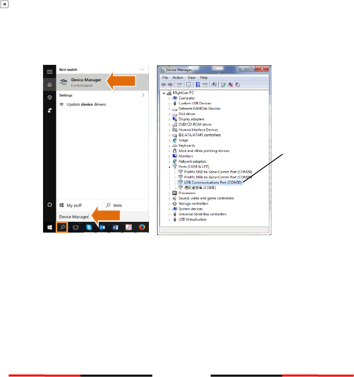
Appendix: How to Determine Serial Port
If you PC/laptop does not have available serial port, you may use a RS232-to-USB
adapter. To find out the proper serial port for connection use the following
instructions.
Windows 7 or VISTA version:
Click on “Start” Select “Control Panel” Select “Device Manager” Click Port
(COM&LPT)
Windows 8 and 8.1:
Click (W)* + I and then click on Control Panel Select “Device Manager” Click Port
(COM&LPT)
Windows 10
+ S type Device Manager in the search box, and select Device Manager from the
list of results. Expand the Ports (COM & LPT) and port number are presented with
numerical number within a parenthesis in the following format (COMXX).
* means Windows button
Serial port
number

Alltek Marine Electronics Corporation
14F-2, No. 237, Sec. 1, Datong Rd.,
Xizhi Dist., New Taipei City, 22161, Taiwan
Tel: +886 2 8691 8568
Fax: +886 2 8691 9569
Email: service@alltekmarine.com
Website: www.alltekmarine.com