Alpheus Digital GATEWAY-101 GATEWAY Panel User Manual
Alpheus Digital Co., Limited. GATEWAY Panel
User Manual

User
Manual

ALDER SIMPLE
2
1-855-999-7872
Table of Contents
INTRODUCTION
(3)
SYSTEM
(23)
Display
PANEL
(5)
Sounds
Panel Location
Exit Delay
Home Screen
Adjust Transmission Delay
Home Screen Icons
Test System Panel
Panel Buttons
System Info
ALARM
(11)
USER PASSCODES (27)
Intrusion Detection
Master Passcode and Verbal
Fire Detection
Password
Carbon Monoxide Detection
Secure Arming
Flood Detection
Reset Master Passcode
Make an Emergency Call
Create Hostage Passcode
Reset Hostage Passcode
SENSORS
(17)
Add New User
Add a Sensor
Reset User Passcode
Remove a Sensor
Remove User Passcode
Rename a Sensor
HISTORY &
Bypass a Sensor
Turn Chime On/Off
MESSAGES
(31)
Turn Voice On/Off
View History
Test Sensor
View Messages
Individual Sensor Settings

USER MANUAL
3
WWW.ALDER.COM
Introduction
This Guide is designed
for owners of the Alder
Simple Security System.
The guide will show
system owners how to
use the basic functions
of the Alder Simple
Panel after the system
has been completely
installed.
USER MANUAL
5
WWW.ALDER.COM
Panel
PANEL LOCATION
Your control panel serves as the heart of your system. Place it in
a central location within 5 feet of an electrical outlet that does not
have a “test/reset” button and is not controlled by a switch.
COMMON LOCATIONS ARE:
· Countertop
· Tabletop
· Shelf
· Desk
· Wall (Professional installation is recommended. Call
Tech Support at 1-888-999-7872)
Avoid placing your panel in hidden locations where a siren would
not be heard. Avoid placing your panel in the closet, garage,
closed laundry room, bathroom, stairwell, near a window where
an intruder might see it, or within 4 feet of electronic devices or
large metal objects such as refrigerators, TVs, or washing
machines.
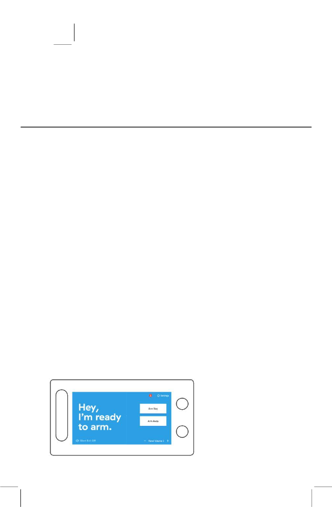
HOME SCREEN
You can wake the panel touchscreen by tapping any area of the
screen or by pressing either the Home or Emergency buttons on
the right side of the panel. By default, the screen will go to sleep
after 3 minutes. To change this setting see ‘Adjust the Display
Timeout time’ on page 27.

ALDER SIMPLE
6
1-855-999-7872
SYSTEM STATUS
Displays the status of the panel. Possible statuses
include the following:
“Hey, I’m ready to arm.”
“I’m armed in Stay mode.”
“I’m armed in Away mode.”
“Hang on, your sensor is open.”
“Hang on, you have multiple sensors that are open.”
SETTINGS
Tap settings and enter your 4-digit Master Code to view and
change your system settings.
MESSAGES
Tap the envelope to view messages. For more details see
“Messages” on page 39.
SILENT EXIT: ON/OFF
Silent Exit is defaulted to “OFF” meaning the panel will beep
during the Exit Delay Countdown when arming Away. (See ‘Arm
the System (Away Mode)’ on page 10). When “Silent Exit” is
“ON” the panel will not beep when arming Away.
CHECK STATUS
(Seen whenever a sensor is open) – tap ‘check status’ to see the
status of all sensors.
PANEL VOLUME
Volume can be adjusted using “- “and “+”. This is the volume
of the chimes and voice. The volume ranges from “0” (off) to
“10” (maximum).
ARM STAY
Arm Stay is used to arm the system when people will be staying
inside. Tapping Arm Stay begins a countdown called the “Exit
Delay”. When the countdown ends, the premises’ doors and
windows will be armed and the motion sensors (with default
settings) will remain disarmed. For more information, see “Arm
the System (Stay Mode)” on page 9.
ARM AWAY
Arm Away is used to arm the system when the home will be
unoccupied. Tapping Arm Away begins a countdown called the
“Exit Delay”. When the countdown ends, ALL sensors will be armed.
For more information, see “Arm the System (Away Mode)” on page
10.
USER MANUAL
7
WWW.ALDER.COM
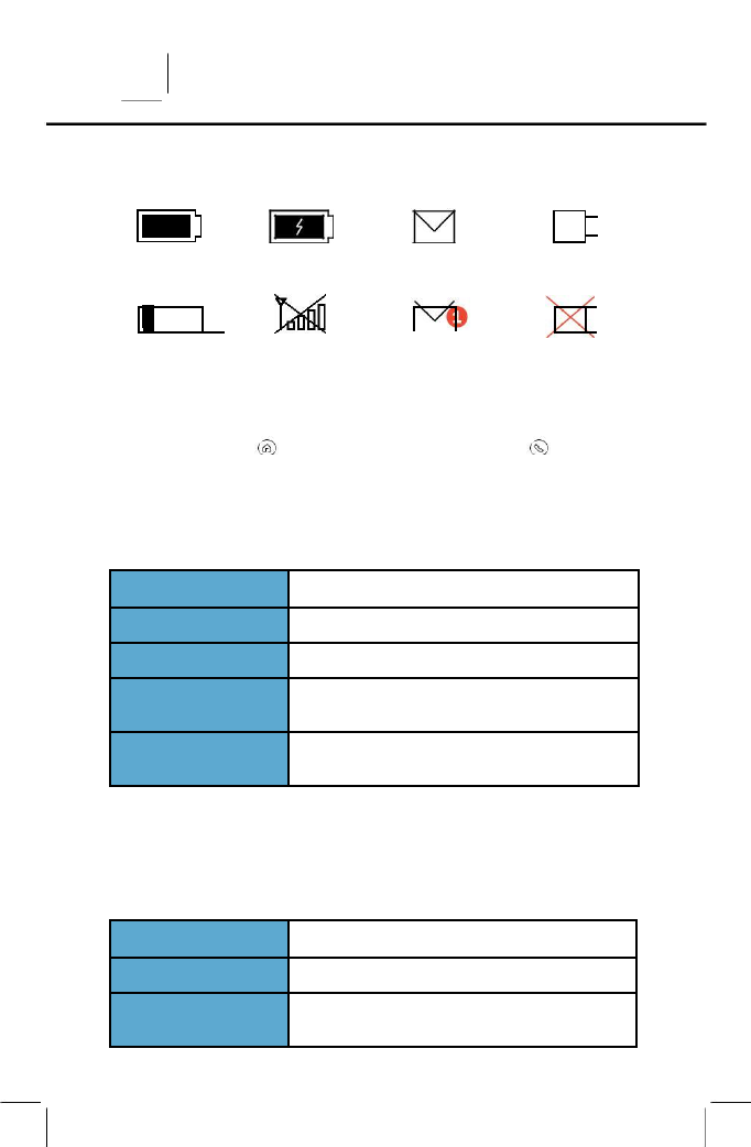
HOME SCREEN ICONS
BATTERY
BATTERY
MESSAGES
AC POWER
FULL
CHARGING
CONNECTED
LOW
NO CELLULAR
UNREAD
AC POWER
BATTERY
CONNECTION
MESSAGE
DISCONNECTED
PANEL BUTTONS
The panel has two LED lighted buttons to the right of the screen.
The Home Button and the Emergency Call Button
HOME BUTTON
Press this button to wake the screen or to return to the Home
screen. The button will change colors according to the system
status as follows:
BLUE
PANEL IS UNARMED AND READY TO ARM
SOLID YELLOW
PANEL IS UNARMED, NOT READY TO ARM
RED
PANEL IS ARMED IN AWAY OR STAY MODE
YELLOW FOR 3 SECS
PANEL IS UNARMED AND A MOTION SENSOR
WAS TRIGGERED
LED LIGHT IS OFF
PANEL IS WITHOUT AC POWER OR LIGHTS
HAVE BEEN TURNED OFF IN SETTINGS
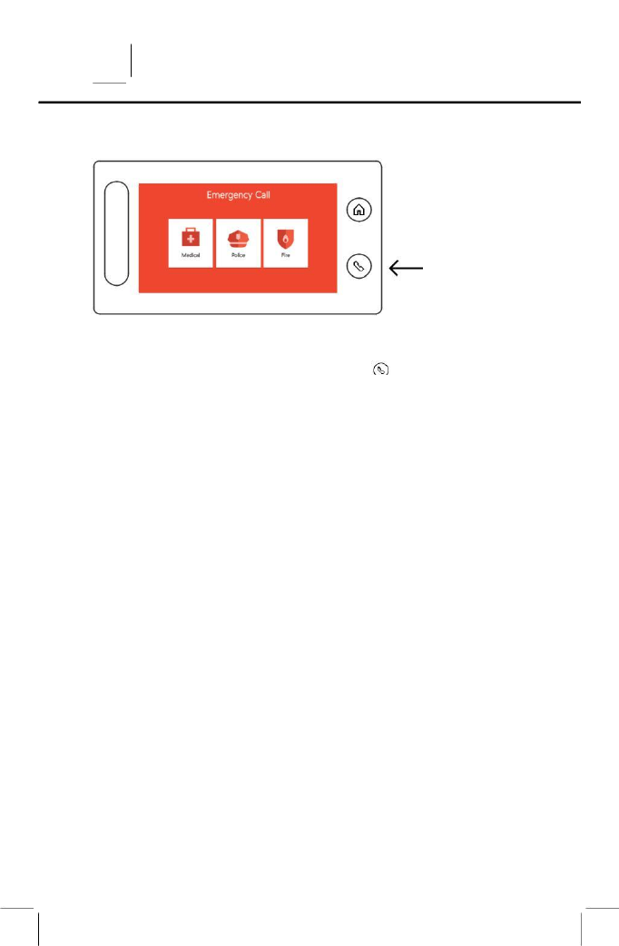
EMERGENCY CALL BUTTON
Press this button as the first step to manually trigger an alarm.
Manual alarm options include Medical, Police, and Fire. See “Make
an Emergency Call” (page 14) for more details. The button will
change colors according to the system status as follows:
RED
PANEL IS MAKING AN EMERGENCY CALL
BLUE
DEFAULT COLOR
LED LIGHT IS OFF
PANEL IS WITHOUT AC POWER OR LIGHTS
HAVE BEEN TURNED OFF IN SETTINGS
USER MANUAL
9
WWW.ALDER.COM
Alarm
INTRUSION DETECTION
In order to arm your system to detect intrusions ensure the panel
status field says, “Hey, I’m ready to arm.” Then arm the system in
Stay or Away mode.
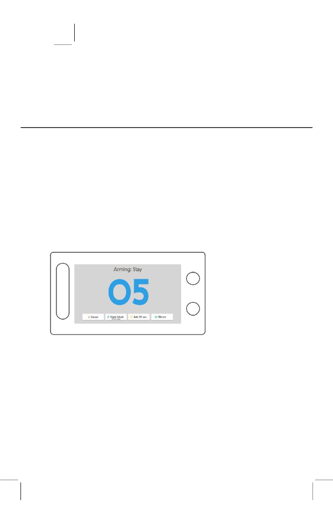
ARM THE SYSTEM (STAY MODE)
Select this mode when people will be staying inside. This mode
arms your doors and windows and leaves the motion sensors
(with default settings) disarmed.
To arm Stay, tap “Arm Stay”. Your system will announce “Arming
Stay”.
Select this mode when the house will be occupied. This mode will
arm ALL anti-burglary sensors except Motion sensors, that have
not been bypassed. During the arming countdown you have the
option to add 30 seconds to the countdown, or tap cancel which
will prompt you to enter your User Passcode to disarm the system.
If you want to silence the countdown-beeping tap the “Silence”
button at the bottom of the arming screen.
Another option is “Night Mode” which will immediately arm your
system and remove any Entry Delay that is set on your door or
motion sensors. This mode is typically used at night when there is
not a reason to have an Entry Delay.
ALDER SIMPLE
10
1-855-999-7872
At the end of the countdown, the system will announce “System
armed stay”, the panel status field will now display “I’m armed in
stay mode.”, and the system will be armed.
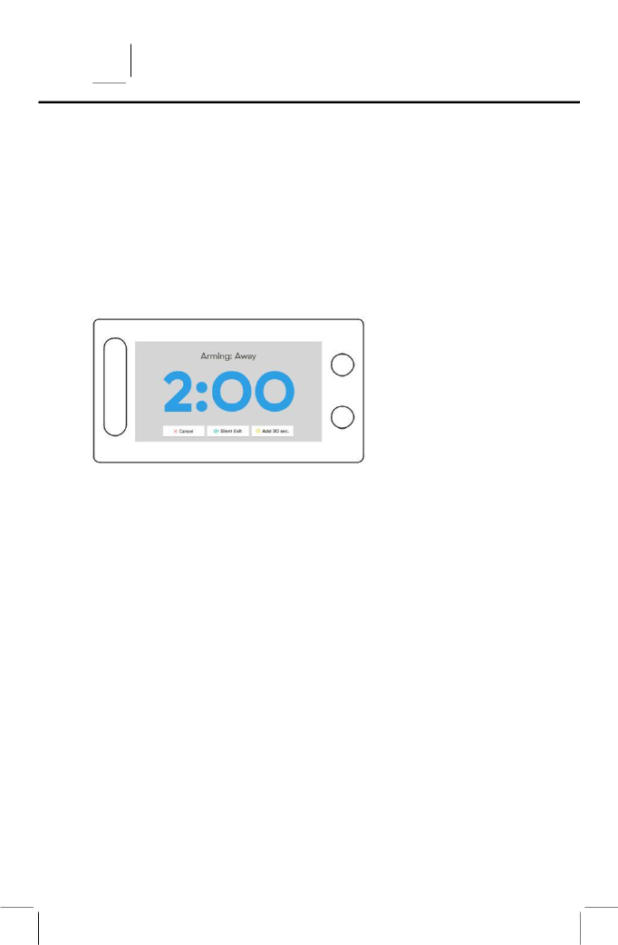
ARM THE SYSTEM (AWAY MODE)
Select this mode when the house will be unoccupied. This mode
will arm ALL anti-burglary sensors (doors, windows, motion
sensors, glass break sensors) that have not been bypassed.
To arm Away, tap “Arm Away”. Your system will announce
“Arming Away”.
If you want to silently arm your system without audible
announcements or the countdown-beeping tap “Silent Exit” at
the bottom left of the home screen or the bottom middle of the
arming screen (image above).
When arming in Away mode and Silent Exit is Off, the countdown
will be accompanied by beeps. You can turn the beeps off mid
countdown by tapping “Silent Exit”. Tapping “Silent Exit” will extend
the countdown length as will opening a door one time
if you need to re-enter the location. You also have the option to
cancel the arming process by tapping “Cancel” and entering a
User Passcode or add 30 seconds to the countdown length by
tapping “Add 30 sec.”
Auto Stay Mode: If for any reason a door sensor is not opened
during the Exit Delay countdown, the system will default to Stay
Mode. This is to prevent the central monitoring station from
receiving false alarms.
BYPASS SENSORS
When you open a door or window that is protected by a sensor,
your home screen will turn yellow and the system status will read,
“Hang on, your sensor is open”. Before you can arm the system
you must either close all open sensors or bypass them.

USER MANUAL
11
WWW.ALDER.COM
THERE ARE TWO WAYS TO BYPASS YOUR SENSORS:
Method 1 Temporary Bypass All
If multiple sensors are open, the system status will read “Hang on,
you have multiple sensors that are open.” Use the “check status”
to display a list of all sensors and their statuses. Possible statuses
include Open, Closed, Active and Tampered. In order to arm your
system without bypassing any sensors, all sensors must be in
“Closed” or “Active” status.
To bypass all open sensors, tap “Bypass, Stay” or “Bypass, Away”.
When asked, “Are you sure you want to bypass? This will arm
your system.” Tap “Yes”. The system will announce that it is
“bypassing sensors and arming” and the arming countdown
will begin. The bypassed sensors will remain bypassed until you
disarm your panel.
Method 2 Long Term Bypass an Individual Sensor
If you want to be able to leave a window open, or for any reason
have your system overlook an individual sensor for an extended
period of time when it is armed, you can bypass an individual
sensor. This will disable the sensor until you turn off the bypass
for that sensor.
To bypass an individual sensor, go to Settings > Enter your 4-digit
Master Code > Sensors > Select the Sensor Type > Tap “Edit” on
the row of the sensor you wish to Bypass > On the “Bypass” Row
tap “ON” > When asked, “Are you sure you want to temporarily
disable this sensor?” Tap “Yes”. This will disable the sensor
until you change the sensor bypass setting back to “OFF” for
that sensor.
To turn off an individual sensor’s bypass go to Settings > Enter
your 4-digit Master Code > Sensors > Select the Sensor Type >
Tap “Edit” on the row of the sensor you wish to no longer
Bypass > On the “Bypass Row tap “OFF”.
DISARM THE SYSTEM
When the system is armed, your system status will read either “I’m
armed in stay mode.” or “I’m armed in away mode.” When the
system is armed, the door, window, motion (per settings), and
glass break sensors are actively protecting the premise and will
alert the system if one of them is triggered. When armed in away
mode, opening a door sensor will begin an audible Entry Delay
countdown rather than instantly triggering the

ALDER SIMPLE 12 1-855-999-7872
alarm. To disarm the system in either mode, enter a 4-digit User
Passcode or press “Disarm” on your Remote. You may also disarm
your panel using the smartphone app. (See page XX for details)
IN THE EVENT OF A BURGLARY ALARM
When the system is armed and a door, window, motion, or glass
break sensor is triggered the following events will happen:
1. For Windows, Motion Sensors (with default “0” entry delay),
and Glass Break Sensors the alarm siren will immediately
sound and continue to sound for four minutes OR until a 4-digit
User Passcode is entered.
2. When a door sensor is triggered the system will immediately start
the Entry Delay countdown to allow time to disarm the system
(Unless Entry delay is set to “0”). The default Entry Delay time
length is 30 seconds and can be adjusted in the individual door
settings (see ‘Change Entry Delay’ on page 19). When the
countdown reaches 0, the alarm siren will sound and continue to
sound for four minutes or until a 4-digit User Passcode is entered.
The alarm siren will be silenced for 5 seconds on the first keystroke
of attempting to enter the user code.
3. After the alarm signal is received by the Central Monitoring
Station, an operator will respond to the reported emergency either
through the 2-way voice device on your panel or directly to your
phone (or emergency contacts if necessary).
CANCELING A FALSE BURGLARY ALARM
If a false alarm is triggered, you can cancel the alarm by entering a
4-digit User Passcode. The siren will stop and the panel will
transmit an alarm cancellation signal to the Central Monitoring
Station. The Central Monitoring Station may still contact you by text
message, through the panel, or by phone to ensure everything is
okay. Be prepared to give them your verbal password (See ‘Master
Passcode and Verbal Password’ on page 33).
USING THE OPTIONAL HOSTAGE CODE
The Hostage Code is used when you need to send a silent duress
signal (for example, if you are being held hostage and are told to
Disarm the system). Entering the hostage code will notify the
Central Monitoring Station that you are in a hostage situation
without the intruder knowing. (see ‘Create Hostage Passcode’ on
page 33.) To activate the hostage code feature, you must create a
hostage code in the User Codes section of your panel. To use your

USER MANUAL
13
WWW.ALDER.COM
hostage code simply enter it to disarm your panel.
FIRE DETECTION
Your Smoke+CO or Smoke/Heat/Freeze sensors are armed at all
times by default. Smoke, Heat, or Freeze detection can be disabled
in the individual Smoke/Heath/Freeze sensor settings. In order to
prevent false alarms, fire protection sensors also have the option of
Fire Verification which requires the sensor to be violated twice in
two minutes, or remain violated for 30 seconds. By default, this
setting is turned off. The setting can be adjusted in the individual
sensor settings. (see Fire Alarm Verification on page 22).
IN THE EVENT OF A FIRE ALARM
If your Smoke or Heat sensor is triggered the following will occur:
The alarm siren will sound and continue to sound for four minutes
or until a User Passcode is entered. Once the Central Monitoring
Station receives the Fire Signal they will act according to the pre-
determined action plan. The Central Monitoring Station WILL NOT
call the panel. You and all others in the house should exit the
premise immediately and call 9-1-1.
CARBON MONOXIDE DETECTION
If your Carbon Monoxide (CO) sensor is triggered the following will
occur: The alarm siren will sound and continue to sound for four
minutes or until a User Passcode is entered. Once the Central
Monitoring Station receives the Carbon Monoxide Signal they will
act according to the pre-determined action plan. You and all
others in the house should exit the premise immediately.
FLOOD DETECTION
Your Flood Sensor is armed at all times.
IN THE EVENT OF A FLOOD ALARM
If your Flood sensor is triggered the following will occur:
The alarm siren will sound and continue to sound for four minutes
or until a User Passcode is entered. The Central Monitoring
Station will contact you and your emergency contacts by the pre-
determined method (panel, phone call, email, text, app notification).
ALDER SIMPLE
14
1-855-999-7872
MANUAL EMERGENCY CALLS
You can notify the Central Monitoring Station of an emergency
event directly from your Alder Simple Security Panel. To do so you
must first press the Emergency Call Button on the right side of
your panel, select the type of emergency (Medical, Police, or Fire)
and verify you want to begin the call by tapping “Call”. This
process has multiple steps in order to limit the risk of accidentally
sending a false alarm signal to the Central Monitoring Station.
To cancel the call tap “Cancel” and enter your User Passcode.
This will send a signal notifying the Central Monitoring Station that
the alarm was cancelled. A Central Monitoring Station operator
may still call.

USER MANUAL
17
WWW.ALDER.COM
Sensors
To access all settings, tap on the Settings icon in the top right
corner of the Home Screen and enter your 4-digit Master Code.
Only the Master Code can access Settings.
ADD A SENSOR
To add a sensor, go to Settings > Enter your 4-digit Master
Code > Sensors > Select the sensor type >Tap “Add Sensor” at
the bottom of the screen >Trigger the sensor (a beep will sound
indicating the sensor has successfully been added) > select a
name for the new sensor based on its location on the premise >
select to add more of the same sensor or tap Done Adding >
Verify your sensor signals are being received by the Central
Monitoring station by running a Complete Sensor Signal Test
(See ‘Complete Sensor Signal Test’ on page 29).
REMOVE A SENSOR
To remove a sensor, go to Settings > Enter your 4-digit Master
Code > Sensors > Select the sensor type > Tap “X” on the row of
the sensor you want to remove > When asked “Are you sure you
want to remove the sensor?” tap “Yes.”
RENAME A SENSOR
To rename a sensor, go to Settings > Enter your 4-digit Master
Code > Sensors > Select the sensor type > Tap “Edit” on the row
of the sensor you wish to rename > Tap the Edit Name icon to
the right of the Sensor Name > Select a new name > Tap “Done”
or “View Sensor Settings”.
BYPASS A SENSOR
To bypass a sensor (turn it off until you turn it back on) go to
Settings > Enter your 4-digit Master Code > Sensors > Select the
sensor type > Tap “Edit” on the row of the sensor you wish to
Bypass > on the “Bypass” Row tap “ON” > When asked, “Are you
sure you want to temporarily disable this sensor?” tap “Yes”.
TURN CHIME ON/OFF
To turn Chimes on or off, go to Settings > Enter your 4-digit
Master Code > Sensors > Select the sensor type > Tap “Edit” on

ALDER SIMPLE
18
1-855-999-7872
the row of the sensor for which you wish to adjust the chime
settings > on the “Chime” row tap “ON” or “OFF” to turn the chime
on or off. If the panel’s universal volume settings are set to “0”
then the chimes will default to “Off” and cannot be turned on
unless the panel volume is set to at least 1.
TURN VOICE ON/OFF
To turn Voice Announcements on or off, go to Settings > Enter
your 4-digit Master Code > Sensors > Select the sensor type >
Tap “Edit” on the row of the sensor for which you wish to adjust
the voice settings > on the “Voice” Row tap “ON” or “OFF.” If the
panel’s universal volume settings are set to “0” then voice
announcements will default to “OFF” and cannot be turned on
unless the panel volume is set to at least 1.
TEST SENSOR
To test a sensor, go to Settings > Enter your 4-digit Master
Code > Sensors > Select the sensor type > Tap “Edit” on the row
of the sensor for which you wish to test > Tap “Test Sensor” on
the bottom of the screen > Trigger the sensor > the panel will
beep and the screen will turn green if the sensor successfully
triggered. Doors and Windows must be opened and closed.
SWINGER SHUTDOWN
This is a non programmable default setting that is enabled when
a sensor or zone is repeatedly tripping. The system will ignore
subsequent trips after a certain number of trips have occured
until the zone is manually restored by disarming the panel or
automatically reset after eight (8) or more hours without further
trips on the zone. Default is set to two trips before Swinger
Shutdown is enabled.
CROSS ZONING
Enabling cross zoning will require multiple zones to be triggered
before the alarm will sound and transmit.
If you wish to create a cross zone, please consult with a technician
by calling technical support at: 1-855-999-7872
DOOR SENSORS
CHANGE DOOR SENSOR ENTRY DELAY
By default, Door Sensors have a 30 second Entry Delay in order
to allow time to disarm the system when a door is opened. If you
want to change a door’s Entry Delay Length, go to Settings >

USER MANUAL
19
WWW.ALDER.COM
Enter your 4-digit Master Code > Sensors > Doors > Tap “Edit” on
the row of the door sensor for which you wish to change the Entry
Delay > on the Entry Delay Row use “-“ and “+” to adjust the
length of the entry delay. Options are in 15 second increments
between 0 and 4:15.
CHANGE DOOR SENSOR BATTERIES
Open the contact sensor (large piece) by finding the small side
with three vertical lines. Insert your fingernail or a flat head
screwdriver into the hole and pull the cover toward you. The
Sensor requires two CR2032 batteries.
WINDOW SENSORS
Window Sensors do not have an entry delay. Triggering a Window
Sensor when the system is armed will always cause the alarm to sound
immediately (unless the window sensor has been bypassed).
CHANGE WINDOW SENSOR BATTERIES
See ‘Change Door Sensor Batteries’ above.
MOTION SENSORS
Motion Sensors have a detection range of 90 degrees and detect
motion up to 45 feet away. They detect movement across a room
or hallway and should be used to secure larger, high traffic areas.
By default, Motion Sensors have an entry delay of 0 seconds. To
preserve battery life, Motion Sensors will go into “sleep mode” for
three minutes after being triggered and not trigger again until
three minutes have passed
CHANGE ENTRY DELAY
To change a Motion Sensor’s Entry Delay Length go to Settings
> Enter your 4-digit Master Code > Sensors > Motions > Tap
“Edit” on the row of the Motion Sensor for which you wish to
change the Entry Delay > on the Entry Delay Row use “+“ and “-
” to adjust the length of the entry delay. The Default is set to 0
seconds. We recommend keeping the motion entry delay set to
“0” unless a door is within range of the Motion Sensor and
opening the door would trigger the Motion Sensor.
ADJUST ACTIVE IN STAY MODE
The “Active in Stay” mode is used when the Motion Sensor is
protecting an area that is very rarely used. To set a Motion Sensor
as Active in Stay Mode go to Settings > Enter your 4-digit Master
Code > Sensors > Motions > Tap “Edit” on the row of the Motion
Sensor for which you wish to change the Active in Stay mode

ALDER SIMPLE
20
1-855-999-7872
status > tap “ON”. The default “Active in Stay” setting is “OFF”
because in nearly all situations you will not want the motion
triggering to set off your alarm while in “Stay Mode”.
PET IMMUNITY
Motion Sensors by default will not detect bodies under 55 pounds.
To change this setting open the back of the motion sensor and
remove the PET pin covering the “55 lbs.” jumper and place it on
the “33 lbs.” jumper if you want your sensor to be triggered by
lighter bodies.
SENSITIVITY
Motion Sensors by default are set to low sensitivity in order to
prevent false alarms. To change this setting open the back of the
Motion Sensor and remove the “SENS” pin covering the “LOW”
jumper and place it on the “HIGH” pin if you want your Motion
Sensor to be triggered more often.
TEST YOUR MOTION SENSOR
To test a Motion Sensor, go to Settings > Enter your 4-digit Master
Code > Sensors > Motion Sensors > Tap Edit on the row of the
motion sensor you wish to test > Test Sensor. Motion Sensors do
NOT have an LED light for testing. You can also test a Motion
Sensor by moving in front of it. The Home button on the panel will
temporarily turn yellow and the History will show the date and time
the motion was triggered. Please note that to extend battery life, a
motion goes to “sleep” mode for up to three minutes after it is
triggered. If the Motion fails to trigger, wait for three minutes and try
again.
If you press the test button on the top right side of the motion, it
will stay awake (be constantly active) for two minutes and every
10 seconds the Panel LED light on the Home button will turn
yellow when it detects motion. You may also check the “History”
screen as sensor triggers will also be recorded in the Panel’s
History.
CHANGE MOTION SENSOR BATTERY
To change the Motion Sensor battery, press up on the button on
the bottom of the sensor and pull the case toward you. The
Motion Sensor requires one CR17345 battery. Replace the
battery and snap the case cover back on the sensor. Make sure
to place the “+” and “-” end of the battery in the proper direction.

USER MANUAL
21
WWW.ALDER.COM
REMOTES
Your Remote can be used to arm and disarm your panel from a
distance or send an emergency signal. The Remote command
buttons will function as long as the remote is within 100 feet of
the panel. There are four buttons on the Remote: Away, Stay,
Disarm, and SOS.
AWAY BUTTON
Pressing and holding the Away Button for three seconds will Arm
your alarm in Away mode and start the Exit Delay countdown.
Unless muted the panel will announce “Arming Away”.
STAY BUTTON
Pressing and holding the Stay Button for three seconds will Arm
your alarm in Stay mode and start the Exit Delay countdown.
Unless muted the panel will announce “Arming Stay”.
DISARM BUTTON
Pressing and holding the Disarm Button for three seconds will
Disarm your system. Unless muted the panel will announce
“System Disarmed”.
SOS BUTTON
Pressing and holding the SOS button for two seconds 2x (twice)
within 10 seconds will trigger the alarm and send an emergency
signal to the Central Monitoring Station.
TURN SOS BUTTON ON/OFF
To Turn a Remote’s SOS button On or Off go to Settings > Enter
your 4-digit Master Code > Sensors > Remotes > tap “Edit” on the
row of the remote for which you wish to change the SOS button >
on the “SOS button” row tap “ON” or “OFF”. Turning your SOS
button “OFF” will disable the button. Pressing the red SOS button
on your remote WILL NOT trigger your alarm or send an
emergency signal to the Central Monitoring Station if your SOS
button setting is set to “OFF”.
CHANGE REMOTE BATTERY
To change the battery of a Remote, remove the screw on the back
of the Remote and open the cover. The Remote requires one
CR2032 battery.

ALDER SIMPLE
22
1-855-999-7872
SMOKE SENSORS
FIRE ALARM VERIFICATION
To turn a Smoke Sensor’s Fire Alarm Verification setting ON or
OFF go to Settings > Enter your 4-digit Master Code > Sensors
> Smoke > Select the Smoke sensor type > Tap “Edit” on the row
of the Smoke Sensor for which you wish to change the Fire Alarm
Verification > on the “Fire Alarm Verification” row tap “ON” or
“OFF” > Verify that you want to change this setting.
Turning Fire Alarm Verification “ON” will require the sensor to be
violated twice in two minutes, or remain violated for 30 seconds
before the alarm will sound. By default, this setting is turned OFF.
SMOKE / HEAT / FREEZE DETECTOR
The Smoke/Heat/Freeze Detector’s function is to alert your
system of smoke, as well as excessive heat or cold detection. It is
designed to provide detection of at least a 35-foot radius. This
detector communicates with the panel to send alarm, tamper, and
battery condition messages to the systems receiver. DO NOT
install the sensor near a kitchen, stove, hot water heater, furnace,
or directly outside a bathroom.
TURN INDIVIDUAL SENSOR ZONES ON/OFF
The Smoke / Heat / Freeze Detector allows you to turn basic
functionality on and off. For example you may have the smoke and
heat sensors activated while freeze detection is suspended. To
adjust these functions go to Settings > Enter your 4-digit Master
Code > Sensors > Smoke / Heat / Freeze > Tap Edit on the row of
the sensor you wish to adjust > on the sensor row tap “ON” or
“OFF”.
TEST A SMOKE / HEAT / FREEZE DETECTOR
To test a Smoke / Heat / Freeze Detector, go to Settings > Enter
your 4-digit Master Code > Sensors > Smoke > Smoke / Heat /
Freeze > Tap Edit on the row of the sensor you wish to test > Tap
the Test Sensor button > Follow the on-screen instructions.
Press the test button on the detector until you hear three beeps.
More sets of three beeps will follow. Before the beeps stop, a
signal will be sent to the panel to tell you the sensor has tested
successfully.
CHANGE SMOKE / HEAT / FREEZE DETECTOR BATTERIES
To change the Smoke/Heat/Freeze Detector batteries twist
the cover of the detector clockwise to remove old batteries.

USER MANUAL
23
WWW.ALDER.COM
This detector requires 3 AAA E92 batteries. Make sure to wait 20
seconds before installing the new battery to ensure a proper power-
down. Insert the batteries in the compartment. Always match the plus
(+) sign on the battery with the flat side of the compartment and the
minus (-) sign on the battery with the spring side of the compartment.
Reinstall by mounting the cover to the base and turning the detector
clockwise.
SMOKE + CO DETECTOR
TEST A SMOKE + CO DETECTOR
To test a Smoke + CO Detector, go to Settings > Enter your 4-digit
Master Code > Sensors > Smoke > Smoke + CO > Tap Edit on the row
of the sensor you wish to test > Tap the Test Sensor button > Follow
the on-screen instructions.
Press the test button in the center on the cover of the detector until
you hear one beep. The detector will have two sets of three beeps (for
smoke) followed by two sets of four quick beeps (for CO) indicating
that the detector is operating normally. Before the beeps stop, a signal
will be sent to the panel to tell you the sensor has tested successfully.
CHANGE YOUR SMOKE + CO DETECTOR BATTERIES
When the detector batteries are low the detector will chirp
approximately every 60 seconds. This detector has a sealed Lithium
battery and is not replaceable. The detector will need to be replaced.
CARBON MONOXIDE (CO) DETECTOR
The Carbon Monoxide (CO) Detector communicates with the panel to
send alarm, tamper, and battery condition messages to the systems
receiver.
TEST A CO DETECTOR
To test a CO Detector, go to Settings > Enter your 4-digit Master
Code > Sensors > Smoke > Carbon Monoxide > Tap Edit on the row
of the sensor you wish to test > Tap the Test Sensor button > Follow
the on-screen instructions.
Press the test button on the cover of the detector until you hear four
quick beeps. The detector will have one more set of four quick beeps
followed by one beep indicating that the detector is operating
normally. Before the beeps stop, a signal will be sent to the panel to
tell you the sensor has tested successfully. If the detector does not
make the beeping sounds the detector will need to be replaced.

ALDER SIMPLE
24
1-855-999-7872
CHANGE CO DETECTOR BATTERIES
To change the CO Detector batteries twist the detector
counterclockwise from its mounting base. Make sure to wait
20 seconds before installing the new battery to ensure a proper
power- down. The CO Detector requires one CR123A battery.
Insert the battery in the compartment. Always match the plus
(+) sign on the battery with the flat side of the compartment and
the minus (-) sign on the battery with the spring side of the
compartment. Reinstall by mounting the detector to the base and
turning the detector clockwise.
MEDICAL PENDANT
The Medical Pendant’s main functionality is to send emergency
signals to the system whether the system is armed or disarmed.
To trigger the button and send emergency signals press the
Medical Pendant Help button in the center for approximately 2
seconds.
TEST A MEDICAL PENDANT
To test a Medical Pendant, go to Settings > Enter your 4-digit
Master Code > Sensors > Medical > Tap Edit on the row of the
pendant you wish to test > Tap the Test Sensor button > Follow
the on-screen instructions.
Press the button on the center of the pendant and hold it for two
seconds. A signal will be sent to the panel to tell you the pendant
has tested successfully.
CHANGE MEDICAL PENDANT BATTERY
To change the Medical Pendant battery remove the top cover by
inserting a small flathead screwdriver into the slot located on the
bottom right corner and twist. This sensor requires one CR123A
battery. When installing the new battery make sure the + sign is
facing out.
FLOOD / FREEZE SENSOR
The Flood / Freeze Sensor is designed to detect pooling and
standing water when it makes contact across the gold probes on
the bottom of the sensor. It also detects the potential of freezing
temperatures that could damage water pipes.
PLACEMENT
Place Flood / Freeze Sensors anywhere you wish to detect a flood
or freezing temperatures. Common locations are: behind a toilet;
under a sink, dishwasher, or fridge; behind a washing machine;

USER MANUAL
25
WWW.ALDER.COM
near a water heater; or in a basement.
TEST A FLOOD / FREEZE SENSOR
To test a Flood / Freeze Sensor, go to Settings > Enter your 4-digit
Master Code > Sensors > Flood > Tap Edit on the row of the
sensor you wish to test > Tap the Test Sensor button > Follow the
on-screen instructions.
Press the test button on the bottom of the sensor and hold it for
two seconds. A signal will be sent to the panel to tell you the
sensor has tested successfully.
CHANGE THE FLOOD / FREEZE SENSOR BATTERY
To change the Flood / Freeze Sensor battery, remove the rubber
feet on the bottom of the sensor then remove the screws and
casing. This sensor requires one CR2450 battery. Be sure to have
the plus (+) side of the battery facing you. After the new battery
has been replaced in the compartment, replace the casing, screws
and rubber feet on the bottom of the sensor.
GLASS BREAK DETECTOR
The Glass Break Detector typically provides a 15-foot maximum
detection range, 360-degree maximum horizontal sensing angle,
and dual-stage glass break detection. Walls, partitions, and other
large objects will obstruct sound and decrease detection range.
Glass Breaks are typically mounted on the ceiling but can be
placed on an opposite or adjacent wall to the window being
protected. Do not place the Glass Break Detector on a window or
glass surface.
TEST A GLASS BREAK DETECTOR
To test a Glass Break Detector, go to Settings > Enter your 4-digit
Master Code > Sensors > Glass Break > Tap Edit on the row of the
sensor you wish to test > Tap the Test Sensor button > Follow the
on-screen instructions.
Rotate the detector counter-clockwise until it stops then remove it
one inch from the mounting plate. Place the detector back on the
mounting plate with the raised marks on the outside edges
aligned and rotate it clockwise to re-mount the detector on the
mounting plate. A signal will be sent to the panel to tell you the
sensor has tested successfully.

ALDER SIMPLE
26
1-855-999-7872
CHANGE GLASS BREAK DETECTOR BATTERIES
To change the batteries simply rotate the detector in a counter-
clockwise motion to remove the detector from the mounting plate.
The Glass Break Detector requires two CR 123A batteries. Insert
the batteries in the compartment. Always match the plus
(+) sign on the battery with the flat side of the compartment and
the minus (-) sign on the battery with the spring side of the
compartment. Align the raised marks on the outside edge of the
detector and mounting plate and rotate clockwise to re-mount the
detector on the mounting plate.

USER MANUAL
27
WWW.ALDER.COM
System
The system menu gives you the option to adjust the Display,
Sounds, and Exit Delay Settings. You can also view System
Info and Test your system.
DISPLAY
ADJUST SCREEN BRIGHTNESS
To Adjust your screen’s brightness Tap Settings > Enter
your 4-digit Master Code > System> Display > on
“Screen Brightness” tap and to adjust the screen
brightness.
ADJUST THE DISPLAY TIMEOUT TIME
The Display Timeout time is the number of minutes the screen
needs to be untouched before timing out (going dark). To adjust
your Display Timeout time tap Settings> Enter your 4-digit Master
Code > System > Display > on the “Display Timeout (min)” Row
tap the “-“ and “+” to adjust the length of time before the screen will
go dark. The options are: 1, 3, 5, or 10 minutes.
CLEAN SCREEN
The Clean Screen option disables the touch screen for 30 seconds
so you can clean your screen without buttons being pressed.
Never use cleaning solvent to clean your screen. Use a damp, lint
free, scratch resistant cloth.
To start the Clean Screen timer tap Settings > Enter your 4-digit
Master Code > System > Display > on the “Clean Screen (30
sec timeout)” Row tap the “Start” button.
TURN LED BUTTONS ON/OFF
To turn your Home and Emergency Call LED Buttons On/Off tap
Settings > Enter your 4-digit Master Code > System > Display >
on the “LED Buttons” Row tap the “ON” or “OFF” button.
SOUNDS
ADJUST THE PANEL VOLUME
To adjust the Panel Volume tap Settings > Enter your 4-digit
Master Code > System > Sounds > on the “Panel Volume” row

ALDER SIMPLE 28 1-855-999-7872
use “+” and “-” to adjust the panel volume. This changes the
volume of voice announcements and chimes. You can also adjust
the Panel Volume by using the “+” and “-” buttons in the bottom
right corner of the Home screen.
TURN CHIME SOUND ON/OFF (FOR ALL SENSORS)
To turn Chime Sounds On or Off for all of your sensors tap
Settings > Enter your 4-digit Master Code > System > Sounds > on
the “Chime Sound (all sensors)” row tap “ON” or “OFF”.
ADJUST THE TOUCH SCREEN VOLUME
To adjust Touch Screen Sound Volume, tap Settings > Enter
your 4-digit Master Code > System>Sounds > on the “Touch
Screen Sound” row use “+” and “-” to adjust the volume of the
clicking noise when the screen is touched.
TURN VOICE SOUND ON/OFF (FOR ALL SENSORS)
To turn Voice Sounds On or Off for all of your sensors tap Settings >
Enter your 4-digit Master Code > System > Sounds > on the “Voice
Sound (all sensors)” row tap “ON” or “OFF”.
CHANGE THE VOICE GENDER (MALE/FEMALE)
To change the gender of the voice announcements tap Settings >
Enter your 4-digit Master Code > System > Sounds > on the Voice
(male/female) row tap “Male” or “Female.”
TEST THE SIREN
To test the Siren tap Settings > Enter your 4-digit Master Code >
System > Sounds > at the bottom of the screen tap “Test Siren.”
EXIT DELAY
ADJUST EXIT DELAY
The Exit Delay is for when you are leaving your home and gives you
time after you arm your alarm to leave the house. The Exit Delay is
defaulted to 60 seconds. The exit delay applies to all sensors. If you
want to change the Exit Delay tap Settings > Enter your
4-digit Master Code > System > Exit Delay > use the “-” and “+” to
adjust the Exit Delay time.
TRANSMISSION DELAY
To prevent false alarms, the panel is defaulted to not transmit an alarm
signal until 30 seconds after the system has been tripped. You can
adjust this time with the Transmission Delay settings. To adjust the
Transmission Delay go to Settings > Enter your 4-digit Master Code >
System > Exit Delay > Transmission Delay > use the

USER MANUAL
29
WWW.ALDER.COM
“+” and “-” to adjust to your desired delay. The options are 0, 15,
30, or 45 seconds.
The Transmission Delay does not apply to Smoke or Flood
sensors which will always send a signal immediately.
If you disarm your system during the Transmission Delay, the
panel screen will notify you that the signal was aborted.
TEST SYSTEM PANEL
The panel provides a variety of different tests you can use to make
sure everything is working correctly. You should test your system
monthly. All system tests can be found by tapping Settings > Enter
your 4-digit Master Code > System >Test System > tap “TEST” on
the row of the item you wish to test and then follow the on-screen
instructions. The system test includes cellular communication,
complete sensor signal test, sensor signal walk test, sound audio,
and siren audio.
COMPLETE SENSOR SIGNAL TEST
A Complete Sensor Signal Test verifies that your sensor signals
are being received by the Central Monitoring Station. To run a
Complete Sensor Signal Test: Tap Settings > Enter your 4-digit
Master Code > System > Test System > tap “TEST” on the row
with the title “Complete Sensor Signal Test” > Trigger each of
your sensors until all sensors have a status of “Verified”. You do
not need to wait for one sensor to reach “Verified” status before
triggering another.
The “TEST” button will turn green if all sensors passed the test and
red if there was a problem. Call Technical Support at 885 999-7872
if ALL sensors do not reach “Verified” status.
Your system will automatically be placed in Test Mode for 10
minutes to allow you to complete the test. Your system will
automatically switch back to Active Mode when you have
completed the test, hit the Back or Home buttons, or the ten-
minute test period ends.
SENSOR SIGNAL WALK TEST
A Sensor Signal Walk Test verifies that your sensor signals are
being received by the panel. To run a Sensor Signal Walk Test
tap Settings > Enter your 4-digit Master Code > System > Test
System > tap “TEST” on the row with the title “Sensor Signal
Walk Test” > Trigger each of your sensors until all sensors have a

ALDER SIMPLE 30 1-855-999-7872
status of “Verified”. You do not need to wait for one sensor to reach
“Verified” status before triggering another.
The “TEST” button will turn green if all sensors passed the test and
red if there was a problem. Call Technical Support at 885 999-7872
if ALL sensors do not reach “Verified” status.
Your system will automatically be placed in Test Mode for 10
minutes to allow you to complete the test. Your system will
automatically switch back to Active Mode when you have
completed the test, hit the Back or Home buttons, or the ten-
minute test period ends.
SYSTEM INFO
This section displays the system information that may be
needed for technical troubleshooting. To access this information tap
Settings > Enter your 4-digit Master Code > System > System Info.
PANEL INSTALL LOCATION
The panel can be installed on the included stand and placed on a
surface such as a table top, countertop, etc. It can also be installed
on a wall with the optional wall-mounting bracket. Professional
installation is recommended for a wall-mounted panel.
The panel install location is defaulted to “Table”. If the panel is
mounted on a wall, the location should be changed to “Wall” by
tapping Settings > Enter your 4-digit Master Code > System >
System Info > tap “Wall” on the panel install location row.

USER MANUAL
33
WWW.ALDER.COM
User Passcodes
MASTER PASSCODE AND VERBAL PASSWORD
Your Master Passcode is the 4-digit user code you set up in the
installation process and can be used to access system settings.
Your Verbal Password is a word or phrase that you established
when you purchased your system. It is used to verify your identity
when an alarm is triggered or when speaking with Alder Simple
about your account.
SECURE ARMING
When Secure Arming is turned “On” the panel cannot be armed
without first entering a User Passcode. To require a passcode to
be entered to arm your system tap Settings > Enter your 4-digit
Master Code > Tap User Passcodes > on the row with “Secure
Arming” tap “ON”. This feature prevents young children or others
from inadvertently arming your system.
RESET MASTER PASSCODE
To Reset a Master Passcode tap Settings > Enter your 4-digit
Master Code > Tap User Passcodes > Tap Reset on the
Master Passcode row > Enter your new 4-digit Master Code.
Note: If you forget your Master Passcode, call our technical
support line and be prepared to give your Verbal Password.
CREATE HOSTAGE PASSCODE
Unlike your other passcodes, your Hostage Passcode will disarm
your system and send a silent hostage emergency signal to the
Central Monitoring Station.
To create your Hostage Passcode tap Settings > Enter your 4-
digit Master Code > Tap User Passcodes > Tap “Create” on the
Hostage Passcode row > Enter your new 4-digit Hostage
Passcode > Enter your 4-digit Hostage Passcode again > Your
Hostage Passcode is now set up. Remember to only use the
Hostage Passcode in emergencies.

ALDER SIMPLE 34 1-855-999-7872
RESET HOSTAGE PASSCODE
To reset your Hostage Passcode tap Settings > Enter your 4-digit
Master Code > Tap User Passcodes > Tap Reset on the Hostage
Passcode row > Enter your new 4-digit Hostage code.
ADD NEW USER
To add a new user tap Settings > Enter your 4-digit Master Code >
Tap User Passcodes > Tap the “+ Add New User” button on the
bottom of the screen > Select a User Number > Enter the new
4-digit passcode. You can add up to 20 new users. Remember,
User Passcodes will NOT have access to panel settings.
RESET USER PASSCODE
To Reset a User Passcode tap Settings > Enter your 4-digit Master
Code > Tap User Passcodes > Tap “RESET” on the row of the
User Code that you wish to reset > Enter the new 4-digit passcode.
REMOVE USER PASSCODE
To Remove a User Passcode tap Settings > Enter your 4-digit
Master Code > Tap User Passcodes > Tap “X” on the row of the
User Code that you wish to remove > When asked, “Are you sure
you want to delete this user?” Tap “Yes” > Tap “Done.”

USER MANUAL
37
WWW.ALDER.COM
History
VIEW HISTORY
Tap Settings > Enter your 4-digit Master Code > Tap History. The
history screen will show up to 200 of the most recent panel
events with the time and date of occurrence. The 201st event will
automatically erase and be replaced by the next oldest event.
Events include sensor opens and closes, sensor triggers, trouble
alerts, sensor tampers, panel tampers, Emergency Calls, sensor
loss of supervision, alarm triggers, disarms, and arms.

USER MANUAL
39
WWW.ALDER.COM
Messages & Trouble
Alerts
MESSAGES
You can view your messages by tapping the envelope on the
Home Screen. The envelope will have a red circle with the number
of unread messages and flash when there is an unread message.
Messages will remain until deleted. To delete a message, tap on
the “x” on the right side of the message’s row.
Whenever your system reports an alarm to the Central Monitoring
Station a new message will appear in your inbox and indicate
which sensor triggered the alarm. Emergency Calls also appear in
Messages
TROUBLE ALERT MESSAGES AND AUDIBLE ALERTS
Trouble Alert Messages appear upon the detection of a system
trouble condition to let you know that your system isn’t working
properly and you need to take action to correct the problem.
Applicable trouble conditions and the actions needed are:
• Panel Loss of AC Power (Check power connection)
• Panel Low Battery (Allow 24 hours to recharge)
• Panel No Battery (Reconnect the battery)
• Panel Communication Failure (Call Tech Support)
• Sensor Low Battery (Replace the sensor battery)
• Sensor Loss of Supervision (Replace the sensor battery)
Trouble Conditions also have an Audible Alert to help draw your
attention to the Trouble Condition and the actions needed. The
Audible Alert for a Trouble Condition will continue to sound once
every four hours until the Trouble Condition is resolved or until you
have turned off Audible Alerts for current Trouble Condition(s).
Audible Alerts only sound between the hours of 9:00 am and 9:00
pm.
To turn off Audible Alerts for current Trouble Conditions tap the
OFF button at the top of the Messages Screen. No more Audible
Alerts will sound until a new Trouble Condition is detected.

Legal & Warnings
LIMITED WARRANTY
This product is warranted against defects in material and
workmanship for one (1) year. This warranty extends only
to wholesale customers who buy directly from Alpheus
Digital Company, LTD or through Alpheus Digital Company,
LTD’s normal distribution channels. Alpheus Digital
Company, LTD does not warrant this product to
consumers. Consumers should inquire from their selling
dealer as to the nature of the dealer’s warranty, if any.
There are no obligations or liabilities on the part of
Alpheus Digital Company, LTD for consequential damages
arising out of or in connection with use or performance of
this product or other indirect damages with respect to loss
of property, revenue, or profit, or cost of removal,
installation, or re-installation. All implied warranties for
functionality are valid only until the warranty expires. This
Alpheus Digital Company, LTD Warranty is in lieu of all
other warranties, expressed or implied.
Waste Electrical and Electronic Equipment
(WEEE) Statement
This symbol on a product or on its packaging indicates that
this product is not to be thrown away with everyday waste.
Instead, it is your responsibility to dispose of electrical and
electronics equipment by handing it over to a designated
collection point for the recycling of waste electrical and
electronic equipment (W.E.E.E.). The separate collection
and recycling of your waste electrical and electronic
equipment at the time of disposal will help to conserve
natural resources and ensure that it is recycled in a
manner that protects human health and the environment.
For more information about where you can drop off your

waste equipment for recycling, please contact your local
city office, or your household waste disposal service, or
the shop where you purchased the product.
WARNINGS
Limitations of Alarm Products
This product should be tested periodically to make sure it
is working properly. The product, if used properly, may
reduce the risk of burglary, robbery, and other adverse
events that have the potential to result in injury or loss of
life; however, Alpheus Digital Company, LTD is not an
insurer. This product is neither insurance nor a guarantee
that such an event will be prevented, and users should
protect themselves with proper insurance. Alpheus Digital
Company, LTD makes no representation that this product
cannot be compromised or circumvented, that it will
provide an adequate warning, or that it will prevent any
personal injuries, property damage, or other losses. Like
any alarm product, it may be bypassed, it is subject to
compromise, and it may fail to warn for a variety of
reasons, including, but not limited to: improper
installation or positioning; improper maintenance;
tampering; dead or improperly installed batteries; sensing
limitations; component failures; receivers; intrusions may
be outside of a product’s designated range and certain
environmental conditions may impact performance, and
audible alarm signals may be outside of hearing range,
muted by doors, walls, and floors, unheard by deep

sleepers or the hearing-impaired, or overwhelmed by
other sounds.
Risk of Noise Induced Hearing Loss
The alarm is equipped with a warning siren. Exposure to
high sound levels or prolonged exposure to the warning
siren can result in Noise Induced Hearing Loss (NIHL)
Wireless Product Notice
Radio controls provide a reliable communications link and
fill an important need in portable wireless signaling;
however, there are some limitations which must be
observed.
• For U.S. installations only: The radios are
required to comply with FCC Rules and Regulations as Part
15 devices. As such, they have limited transmitter power
and therefore limited range.
• A receiver cannot respond to more than one
transmitted signal at a time and may be blocked by radio
signals that occur on or near their operating frequencies,
regardless of code settings.
• Changes or modifications to the device may
void FCC compliance.
• Infrequently used radio links should be tested
regularly to protect against undetected interference or
fault.
• A general knowledge of radio and its vagaries
should be gained prior to acting as a wholesale distributor
or dealer, and these facts should be communicated to the
end users.
FCC Part 15: Class B Digital Device Statement
If the module’s label is not visible when installed, then an
additional permanent label referring to the enclosed
module: “Contains Transmitter Module FCC ID:
OC7GATEWAY-101” must be placed on the rear panel in
a visible location.
FCC ID: OC7GATEWAY-101
This equipment complies with FCC radiation exposure
limits set forth for an uncontrolled environment. This

equipment should be installed and operated with
minimum distance 20cm between the radiator and your
body. This transmitter must not be co-located or operating
in conjunction with any other antenna or transmitter.
This devise has been tested and found to comply with the
limits for a Class B digital device pursuant to Part 15 of FCC
Rules. Operation is subject to the following two conditions:
1. This device may not cause harmful
interference, and
2. This device must accept interference
received, including interference that may
cause undesired operation.
These limits are designed to provide reasonable
protection against harmful interference in a residential
installation. This equipment generates and can radiate
radio frequency energy and, if not installed and used in
accordance with the instructions, may cause harmful
interference to radio communications. However, there is
no guarantee that interference will not occur in a
particular installation. If the equipment does cause
harmful interference to radio or television reception,
which can be determined by turning the equipment off
and on, the user is encourage to try to correct the
interference by one (1) or more of the following measures:
a. Reorient or relocate the
receiving antenna
b. Increase the separation between
the equipment and receiver
c. Connect the equipment into an
outlet on a circuit difference
from that to which the receiver
is connected

d. Consult the dealer or an
experienced radio/TV technician
for help.
Note: Any changes or modification
made to this device that are not
approved by Alpheus Digital
Company, LTD may void the
authority granted to the user by the
FCC to operate this equipment.
.
.