Ampy Metering 5252-01 Radio Enabled Electricity Meter User Manual 5252 Meter Manual Version 1 1
Ampy Metering Ltd Radio Enabled Electricity Meter 5252 Meter Manual Version 1 1
Contents
- 1. User Manual
- 2. User manual
User Manual

5252 Meter Functionality User Manual
Ampy Metering Ltd
Version 5252 1.1
© Copyright Ampy Metering Ltd, 1 Lysander Drive Northfields Industrial Estate Market Deeping PeterboroughPE6 8FB
The information contained in this document is the property of the authors. It may not be copied, stored on an information retrieval system or communicated
by electronic mail or others means without the express permission of the authors.
Table of Contents
TABLE OF CONTENTS III
AMPY 5252 METER FUNCTIONS 1
METER OVERVIEW 2
APPROVAL STANDARDS 2
ELECTRICAL PARAMETERS 2
PERFORMANCE REQUIREMENTS 3
METROLOGY OUTPUT LED 3
SUPPLY LOSS REPORTING (LAST GASP) 3
OPTICAL PORT 4
METER DISPLAYS 5
DISPLAYED INFORMATION 6
OPERATION ICONS 6
ENERGY AND INFORMATION DISPLAYS 7
TIME AND DATE DISPLAYS 8
TAMPER DISPLAYS 8
PREPAY DISPLAYS 9
WARNING AND ENGINEERING DISPLAYS 10
DISPLAY CYCLING 11
EXTENDED DISPLAY 11
LCD BOTTOM-NUMBER INDICATIONS
USED BY PLC COMMUNICATIONS 12
LCD ICON INDICATORS 13
RATES AND TARIFFS 14
TIME OF USE RATE SWITCHING AND
POWER BAND TARIFFS 15
TARIFF RATE PLAN/ DEMAND RESPONSE
INDICATION ASSIGNMENT 16
BLOCK TARIFF POWER SWITCH
THRESHOLD VALUES 18
TARIFF PLAN 19
DEMAND RESPONSE INDICATION
ASSIGNMENT 20
METER OPERATION 21
REAL TIME CLOCK 22
DAYLIGHT SAVING 22
PREPAYMENT OPERATION GENERAL 22
HOLIDAYS 22
SEASONAL NON DISCONNECT 23
FRIENDLY NON-DISCONNECT 23
TARIFF STORAGE 23
FIXED CHARGES 23
ACCOUNTANCY CONFIGURATION 24
CREDIT TRANSACTIONS 24
CREDIT INFORMATION LOG 24
DEMAND RESPONSE 24
REMOTE DISCONNECT/RECONNECT 26
SAFETY RECONNECTION 26
METER TEST MODE (METROLOGY
TESTING) 26
FIELD TEST MODE 26
PROFILING 27
MAXIMUM DEMAND 27
ENERGY REGISTRATION 27
TAMPER DETECTION 27
POWER OUTAGE REPORTING 28
SPECIAL CONTACTOR OPERATION 28
DATA LOGGING 28
EMERGENCY TIME LOG 29
SELF DISCONNECTS LOGGING 29
DECOMMISSION / RE-COMMISSION DATA29
METER REGISTERS 31
CREDIT/DEBT REGISTER 32
MAXIMUM CREDIT REGISTER 32
ACCOUNTANCY CONFIGURATION 32
DECIMAL POINT CONFIGURATION 32
MAXIMUM DEMAND PERIOD 32
ACTIVE RATE 32
KWH REGISTERS 32
$ PER UNIT FOR RATES 1 TO 4 32
USAGE YESTERDAY 32
$ USAGE PER HOUR 33
KW USAGE PER HOUR 33
$ USAGE TODAY 33
$ USAGE THIS MONTH 33
$ USAGE LAST MONTH 33
ACTIVE FIXED CHARGE 1 AND 2 33
FUTURE FIXED CHARGE 1 AND 2 33
FUTURE FIXED CHARGE 1 AND 2
ACTIVATION DATES 33
SEASONAL NON DISCONNECT START AND
END DATE/TIME 33
OPERATION MODE 33
POWER FAIL COUNT 34
WAKE UP REGISTER 34
CREDIT TRANSFER REGISTER 34
CREDIT HISTORY 34
CREDIT INFORMATION (TRANSFER) LOG 34
FRIENDLY DEBT REGISTER 34
ENERGY REGISTRATION MODES 35
VOLTAGE REPORTING 36
COMMUNICATION 37
PERIODIC - DAILY READS 38
PERIODIC - MONTHLY READS 38
PERIODIC - TIME UPDATE 38
PERIODIC - LOAD PROFILE COLLECTION 38
INSTANTANEOUS - POWER OUTAGE
REPORTING 39
INSTANTANEOUS - READ REQUEST 39
INSTANTANEOUS -
DISCONNECT/RECONNECT REQUEST 39
INSTANTANEOUS – PREPAY TRANSACTION
39
INSTANTANEOUS REQUEST – CONFIG
UPDATE 39
GLOBAL BROADCAST – DEMAND
RESPONSE 40
DEFINITIONS 41

5 2 5 2 M E T E R F U N C T I O N A L I T Y U S E R M A N U A L
1
11
1
AMPY 5252 Meter functions
Functions of the 5252 Meter
Chapter
1
C O N T E N T S
Meter Overview
Approval
Standards
Operational
Requirements
Electrical
Parameters
Performance
Requirements
Metrology
Output LED
Supply Loss
Reporting
Optical Port
5 2 5 2 M E T E R F U N C T I O N A L I T Y U S E R M A N U A L
2
22
2
Meter Overview
This manual covers the Type 5252 Meter Radio based Tokenless prepay system for the
North American market. The meter includes a 2 way radio component. This will allow the
meter to provide Tokenless prepay, Demand response and remote disconnect when
operating as a standard post paid meter.
The meter is a single phase and network meter measuring active energy across four time of
use rates, is fitted with a disconnect switch for the disconnection of supply, radio module for
communicating with a base station and PLC modem for communicating with the in-home
unit. The in-home unit provides the customer usage information, demand response signaling
and the ability to close the meters contactor after a reconnection command.
Approval Standards
Description Document Number
Accuracy Tests and Internal influences ANSI C.12.1
Electrical Safety Requirements of Equipment for Laboratory Use
(Meter, US)
UL6101B-1
Electrical Safety of Measuring & Test Equipment, part1: General
Requirements (Meter, CA)
CSA C2.22 No.1010-1
Code of Federal regulation, Title 47
Telecommunication Part 15 – Radio Frequency Devices
FCC Part 15 Carrier Current
Devices & Digital Devices
Industry Canada interference causing Equipment
Standard-Digital Apparatus & Carrier Current Devices
ICES-003 & ICES-006
The meter described in this guide emits radio frequency energy. Calculations
show that at a distance of 20cm, the power density is below the FCC limits for
RF radiation exposure.
This device complies with part 15 of the FCC Rules. Operation is subject to the
following two conditions: (1) This device may not cause harmful interference, and (2) this device
must accept any interference received, including interference that may cause undesired operation.
This device is specifically designed to be used under section 15.247 and 15.249 of the FCC rules
and regulations. Any unauthorized modification or changes to this device may void the user's
authority to operate this device
Electrical Parameters
The meter operates on a single phase, three wire circuit with a reference voltage of
120/240V, 60Hz. Meter Form 2S
The meter will also operate on a three wire network connection (two phases of a three phase
four wire system) with a reference voltage of 120/208V, 60Hz. Meter Form 12S.
The meter when powered up will be fully operational with mains voltages above 176V.

5 2 5 2 M E T E R F U N C T I O N A L I T Y U S E R M A N U A L
3
33
3
The meter will power fail and shut down below 166V.
The reference frequency is 60Hz
The meter has a test amps rating of 30 Amps
The meter has a maximum rated current of 200A
Performance Requirements
The meter has been designed to have a minimum product life of 15 years.
Energy measurement accuracy is approved to class 200 (Cl 200).
The meter is approved to ANSI C12 and relevant UL (CSA) safety standards.
The operating temperature range: –30°C to +70°C
The storage temperature range: -40°C to +80°C
While on supply the meter’s time is kept to within +- 5minutes of local time at all times.
Metrology output LED
To indicate energy usage the meter optical port is fitted with an infrared LED. The LED
flashes according to the energy recorded.
When registering energy the LED flashes at a rate of 1 pulse per Wh of energy recorded
(1000 pulses kWh, I Kh).
The metrology LED will be permanently on when creep lock is active.
To give a visual indication of energy registration, an indicator flashing at the same rate as the
metrology LED is shown on the display.
Supply Loss Reporting (Last Gasp)
If a voltage interruption of approx. 2 mains cycles in duration is detected, the meter will
trigger a Power loss report to radio module.
The radio module will transmit to the Central System once an available transmission slot is
detected.
If supply is restored following the interruption but before the message is sent, the meter will
cancel the message to the Radio module. This will prevent messages being sent where the
supply loss was of very short duration.

5 2 5 2 M E T E R F U N C T I O N A L I T Y U S E R M A N U A L
4
44
4
Optical Port
The Meter is fitted with an optical data port which meets the ANSI standard C12.18 Section
4.8 “Layer1 – Physical”. The optical probe is used for programming and data collection.

5 2 5 2 M E T E R F U N C T I O N A L I T Y U S E R M A N U A L
5
55
5
Meter Displays
Meter Display Information
Chapter
2
C O N T E N T S
Displayed
Information
Operational
Icons
Energy and
Information
Displays
Time and Date
Displays
Tamper
Displays
Pre-Pay
Displays
Warning and
Emergency
Displays
Display Cycling
Extended
Display
LCD Bottom
Numbers
indication
LCD Icon
Indicators
5 2 5 2 M E T E R F U N C T I O N A L I T Y U S E R M A N U A L
6
66
6
Displayed Information
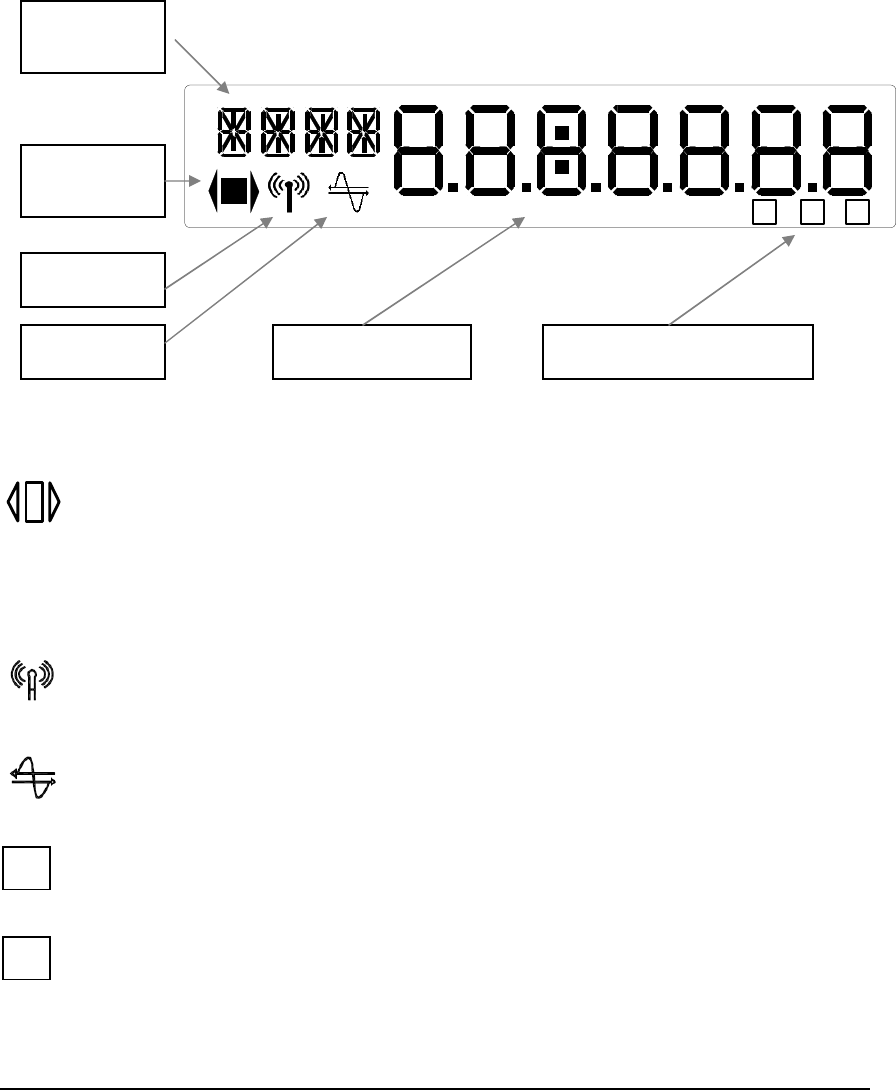
The meter has a cycling display which is configurable by the utilities. The meter display uses
a set of 4 starburst characters, 7 seven-segment characters and specific icons to show
operation and status of meter.
The display scroll rate is configurable in seconds by the Central System software.
The following diagram shows an example of the Meter display showing all functionality.
Operation Icons
Power Registration Icon - Centre rectangle/square is shown if the contactor is closed
when the meter is in either credit or prepayment mode.
The Centre rectangle/square will flash each time a Wh of energy has been consumed at same rate
as metrology LED. The side triangles represent energy direction. NOTE: Initially only forward
(RH) indicator will be used, reverse triangle is for future use.
Radio Reception Icon - Radio icon will be shown when the meter is able to
correctly hear and decode messages from a base station.
PLC Icon - PLC icon will be shown when the meter is able to correctly hear and
decode messages from a CIU.
Tamper Detection - Icon is shown if meter detects tamper event. Icon is reset
following a reset command from the system or optical port.
Prepayment Mode - Icon is shown if meter is configured to prepayment mode
1 2 345PE P
T
Display
Header
Metrology
Indicator
Radio Icon
PLC Icon
Service Indicators
Operating Mode Icons
T
P
5 2 5 2 M E T E R F U N C T I O N A L I T Y U S E R M A N U A L
7
77
7
Emergency Code / Wake-up Indicator - Symbol is shown if the meter has
accepted a valid emergency e-code or is in a 10-minute wake-up period following a
wake-up message from the CIU under battery power. During a wake up period the symbol
will be flashed.
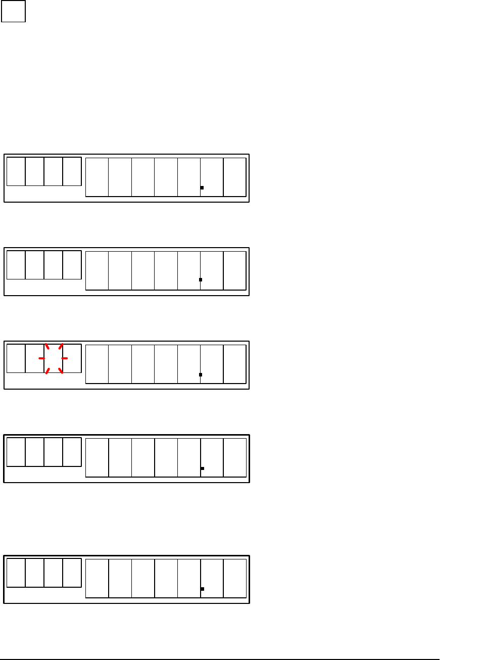
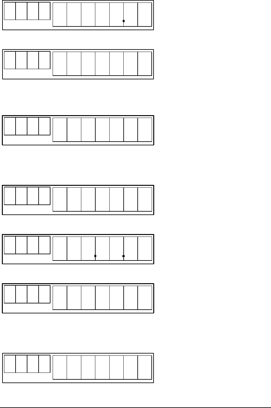
Energy and Information Displays
The Energy registers of the meter show 5 whole numbers with the option of 0, 1 or 2
decimal places unless configured to 3 decimal places of testing purposes via the optical port.
The register will roll over to zero after 99999.99.
Rate registers are shown as -
R 1
0 0 0 0 0 0 0
Total energy register – The total energy register displays the sum of rate 1 to 4 energy
registers. The register will roll over to zero after 99999.99.
T O T
0 0 0 0 0 0 0
Active rate – The active rate will be shown by flashing the rate enunciator (configurable) on
the active energy register.
R 1
0 0 0 0 0 0 0
Received Energy – The meter will record any received (export/reverse) energy to a specific
register.
R C V D 0 0 0 0 0 0 0
Maximum Demand – The MD registers hold the highest demand value recorded over the
configured demand period operating over a specific TOU period. The meter will be able to
display four MD registers numbered MD 1 to 4. The MD register will be shown to 2 decimal
places.
M D 1 0 0 0 0
E
5 2 5 2 M E T E R F U N C T I O N A L I T Y U S E R M A N U A L
8
88
8
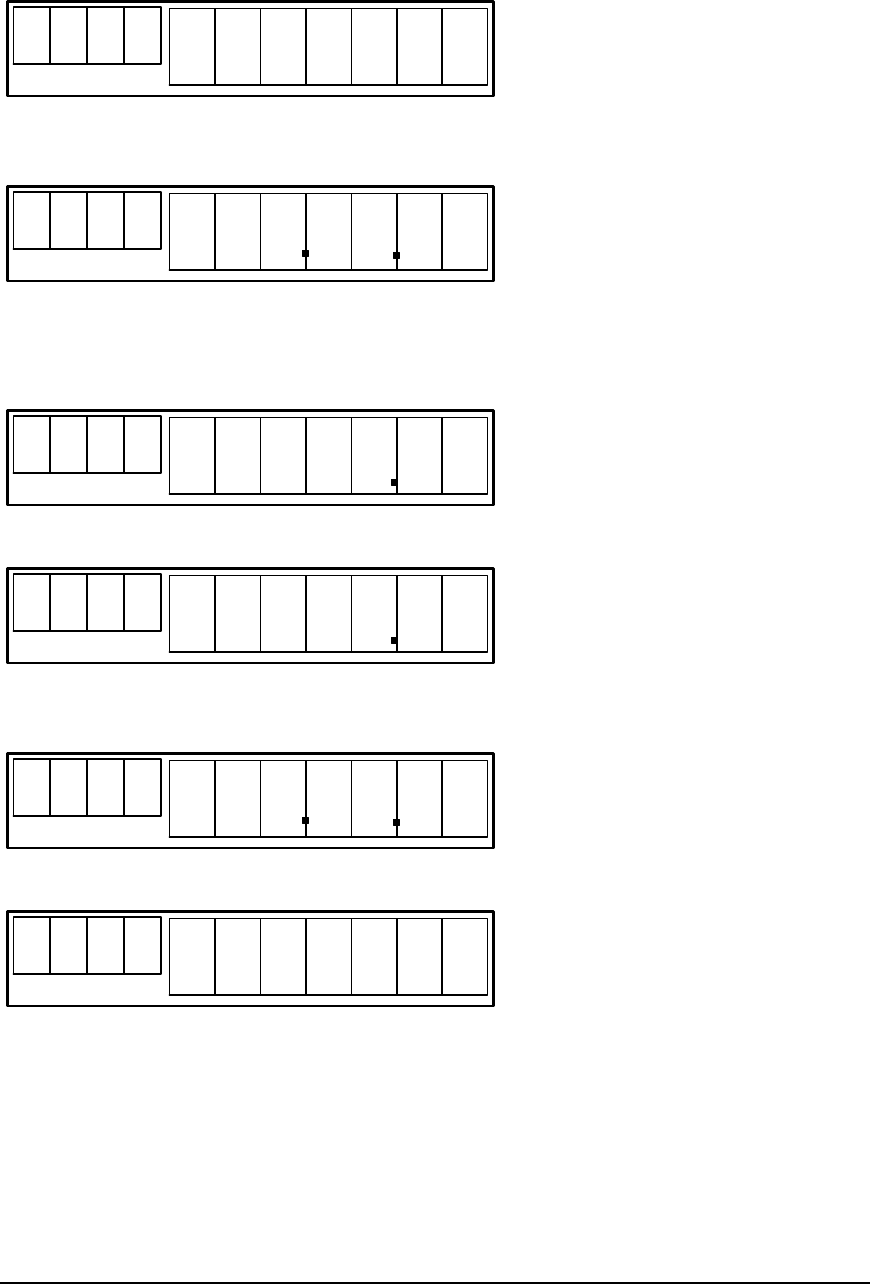
Instantaneous Power – An indication instantaneous of power consumed in kW
P
W
R
0 0 0 0
Display test – All segments including all icons to be shown
8 8 8 8
D8 8 8 8 8 8 8
Tariff Plan Indication – The meter will display a 4-character rate plan ID to identify the rate
plan configured into the meter. The ID will be sent from the CS to accompany the tariff
plan configuration. The ID is displayed in the 4-starburst display characters.
X X X X
D
t r f i d
Time and Date Displays
The Time in the meter is shown as:
T I M E HH : MM
Standard Date format is displayed as:
D A T E MMDDY Y
The optional ISO standard format (Canada) is displayed as:
Y Y Y Y - MM - DD
Tamper Displays
Tamper Count Display shows- number of time meter has detected a tamper attempt
T P R c
0 0
5 2 5 2 M E T E R F U N C T I O N A L I T Y U S E R M A N U A L
9
99
9
Tamper Time Display shows– last time the meter detected a tamper attempt
T P R T HH : MM
Tamper Date Display shows – Last date the meter detected a tamper attempt. This will
change to YY.MM.DD if display is configured to ISO (Canada) standard format.
T P R D MMDDY Y
Prepay Displays
The Credit level Display shows – remaining credit
C R E D 0 0 0 0 0 0
Last Payment value Display shows – Value of last payment made to meter
L P A Y 0 0 0 0 0 0
Last credit date Display shows - Last date when a value of credit was transferred
If configured to ISO Standard Format (Canada) the date will be displayed as YY.MM.DD
C D
D
MMDDY Y
Credit transaction identifier Display shows – ID of last top-up transaction
C - I D
D
n n - n n n n
5 2 5 2 M E T E R F U N C T I O N A L I T Y U S E R M A N U A L
10
1010
10
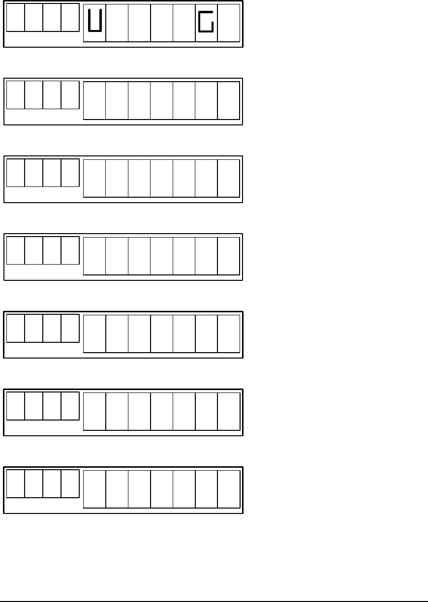
Warning and Engineering Displays
Low Voltage Warning Display shows – Warning message shown if supply voltage is below
preset voltage limit.
L OW
D
o L t A E
Power Fail message Display shows – Mains supply has failed.
P
W
R
DF A I L
PLC Node Display shows - Address used to identify data packets sent by the Payment Unit
N
O
D E
D0 0 0 0 0
Program Download Active
P R O G
DAC T I V E
Verifying downloaded program
P R O G
D
V E r
Error detected in downloaded program
P R O G
D
E r r o r
Reprogramming the flash-EPROM
P R O G
D
F L A SH
5 2 5 2 M E T E R F U N C T I O N A L I T Y U S E R M A N U A L
11
1111
11
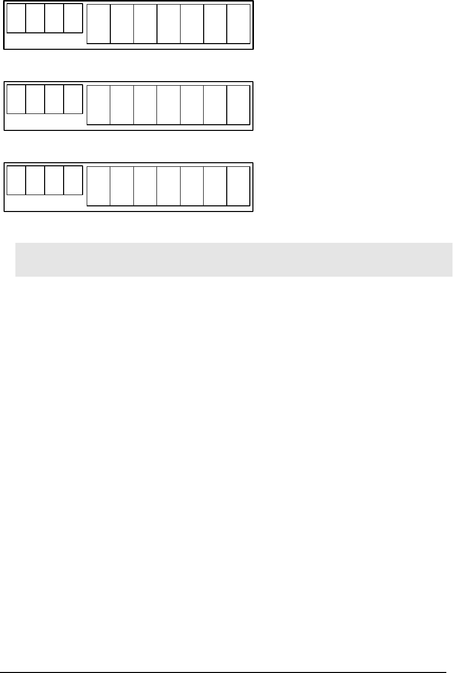
Verifying reprogrammed flash-EPROM
P R O G
D
V F L AS H
Reprogramming completed successfully
P R O G
Dd On E
Reprogramming failed
P R O G
DF A I L
Note: Please note that all energy registers can be configured to show one, two or no
decimal places.
Display Cycling
The meter shall be capable of displaying a configurable display sequence. The display
sequence can be made up from any of the available meter displays (except engineering
displays for Ampy use) in any order.
The display sequence is advanced automatically with the time delay between advances
configurable between 1 and 60 seconds. Display end is not to be shown at the end of the
sequence.
Extended Display
Any of the above displays can be configured into the extended display usually to provide
extra information that may be useful for a field technician during diagnostic activities. For
example, diagnostic displays relating to PLC information would normally only be viewed
through the extended display facility.
The extended display is activated through an operation provided by the AMPY Field Unit
Software. The extended display activates for 60 seconds, and then the meter will revert back
to the normal display cycle. Each display will scroll at the configured display scroll rate.
Display scroll rate is configured through the Central System.
5 2 5 2 M E T E R F U N C T I O N A L I T Y U S E R M A N U A L
12
1212
12
LCD Bottom-Number Indications used by PLC Communications
The table below shows the flashing numbers that may be displayed in the meter (possible
permutations) that may be viewed and their description.
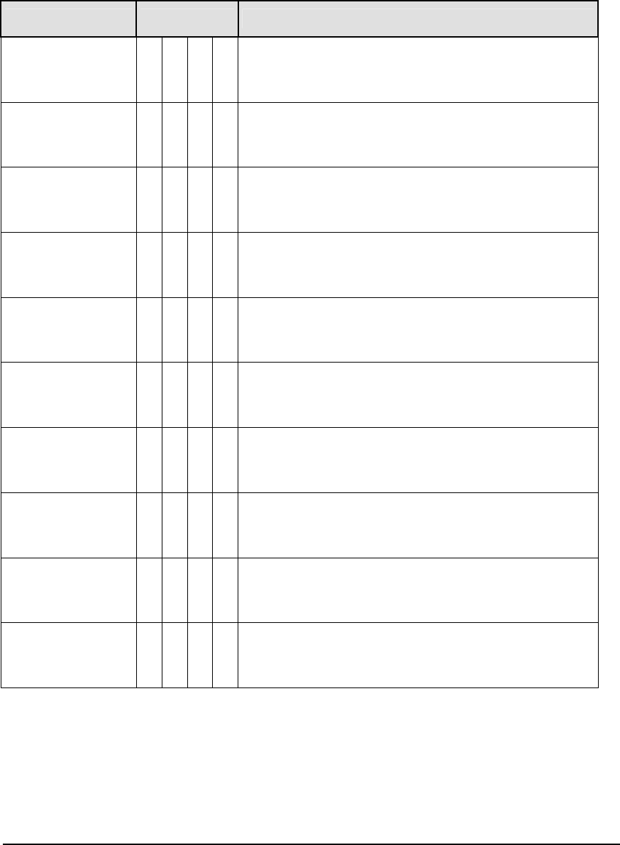
Condition Indication Explanation
Config Fail 1 2 3 4 PLC hardware failing to configure correctly
Ping Response 3 4 Valid response received to “ping” test packet just
sent
Valid Packet 3 Good (enhanced) packet received from associated
CIUnit (on own address)
Valid Packet 2 3 Good (old format) packet received from associated
CIUnit (on own address)
Wrong Addr 2 Packet seen for other destination address on wire;
other normal traffic
Time Out 1 All of packet did not arrive within expected interval;
could be due to a noise burst or to poor signal level
Corrupt Packet 1 2
Complete packet received for own address but
corrupted by noise or collision on wire (bad frame
check)
Bad Packet 1 4
Complete packet received for own address but
containing inconsistent control information (CIUnit
problem?)
Duplicate Addr 2 4 Another meter has the same PLC address and
customer number
Internal Error 1 2 4 Possible software error detected in meter
Indication “5” (steady) — radio out-station in relay mode
Indication “5” (alternating) — IR optical interface signed-on
5 2 5 2 M E T E R F U N C T I O N A L I T Y U S E R M A N U A L
13
1313
13
LCD Icon Indicators
The table below shows details for the Power Registration Icon Indicators that may be
displayed in the meter (possible permutations) that may be viewed and their description.
Power Registration Icon indicators
Action Description
Indication BLOCK Contactor closed (blink-off every 1Wh)
Indication RIGHT-ARROW Importing energy (forward power)
Indication LEFT-ARROW Exporting energy (reverse power)
Indication LA—BLK—RA (alternating) Contactor drive failure, “safe-mode”
The table below shows details for the Radio Reception Icon Indicators that may be displayed
in the meter (possible permutations) that may be viewed and their description.
Radio Reception Icon Indicators
Action Description
Indication RADIO (steady) Radio out-station attached to a base-station
Indication RADIO (blink-off) Radio interface activity
Indication RADIO (alternating) Radio out-station unlocked or hunting
The table below shows details for the PLC Icon Indicators that may be displayed in the
meter (possible permutations) that may be viewed and their description.
PLC Icon Indicators
Action Description
Indication PLC (steady) PLC interface configured & enabled
Indication PLC (blink-off) PLC interface activity
Indication PLC (alternating) Trying to configure PLC interface
The table below shows details for the Tamper, emergency and Pre-Payment Icon Indicators
that may be displayed in the meter (possible permutations) that may be viewed and their
description.
T E and P Icon indicators
Action Description
Indication SQUARE-T Tamper detected
Indication SQUARE-E (steady) Emergency connection active
Indication SQUARE-E (alternating) Wake-up connection active
Indication SQUARE-P Prepay mode active
Indication TEP (repeating) Metrology test mode active

5 2 5 2 M E T E R F U N C T I O N A L I T Y U S E R M A N U A L
14
1414
14
Rates and Tariffs
Rates and Tariffs applicable to the meter
Chapter
3
C O N T E N T S
Time of use
Rate Switching
and Power
bands
Tariff Rate Plan
Demand
Response
Indicator
Block Tariff
Power Switch
Threshold
Values
Tariff Plan
Demand
Response
Indication
Assignment
5 2 5 2 M E T E R F U N C T I O N A L I T Y U S E R M A N U A L
15
1515
15
Time of use Rate Switching and Power Band Tariffs
Time of use kWh rate recording operates according to a time switching matrix. The energy
recorded at a particular rate may be charged at a fixed price throughout the effective time of
the tariff or at a variable price according to the amount of power consumed.
TIME SWITCHING
The meter is capable of holding a total of 15 time switches. Each time switch consists of:
1. Switch start time in hours and minutes
2. Rate number the meter is to switch to (1 to 4)
3. Day of the week in which the switch should operate (Mon - Sun)
Enabled switching days Time
Switch Start Time Rate Mon
Tue Wed
Thru
Fri Sat Sun
1 HH:MM
2 :
3 :
4 :
5 :
6 :
7 :
8 :
9 :
10 :
11 :
12 :
13 :
14 :
15 :
The meter uses the RTC time (with any DST alterations) to switch between the configured
TOU rates. A configured time switch will only operate on the configured days of the week.
On reaching the start time of the a time switch the meter will show the defined rate as the
active rate and record and consumed energy into the appropriate rate register
The meter will hold a second set of future time switches as described as above. The second
set of switches will be assigned a future activation date, upon reaching this date the meter
will overwrite the active switches with the second set. This will allow seasonal rate switching
in the meter.
Example: If a three rate tariff was required with rate 1 active 00:00 to 07:00 and rate2 active
for the rest of the day on weekdays with rate 3 active on weekend, as shown below:
Rate 1
Rate 2
Rate 3
Mon Tue Wed Thur Fri Sat Sun

5 2 5 2 M E T E R F U N C T I O N A L I T Y U S E R M A N U A L
16
1616
16
To operate this tariff the following time switches would be required in the rate-switching
plan:
Enabled switching days Time
Switch Start Time Rate Mon Tue Wed Thru
Fri Sat Sun
1 00:00 1
2 07:00 2
3 00:00 3
Tariff Rate Plan/ Demand Response Indication Assignment
Billing Period
The meter can calculate several features over a configurable billing period. The billing period
consists of a configured start date and duration specified as either a number of days or
calendar months.
The Billing Period duration is defined in the range of: 1 to 115 days; or 1-12 calendar
months.
The Billing Period has a start date defined as DDMM. The day range is between 1st and 28th
day. The month range is 1-12, January to December. No year is applied.
The Billing Period end date is calculated as the start date plus the number of days or calendar
months of the Billing Period. Where a monthly period is applied the meter will use the day
specified in the start date as the start day of the next period following the specified number
of month’s duration. The Billing Period ends at 24:00 on the Billing Period end date.
At the end of a Billing Period the next Billing Period shall start automatically.
Features using the Billing Period for calculation and logging of data include:
Block Tariff (start day)
Data logging
Monthly reads
5 2 5 2 M E T E R F U N C T I O N A L I T Y U S E R M A N U A L
17
1717
17
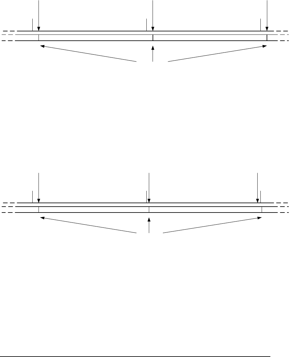
Example 1
If a billing period were specified as 1 calendar month in duration starting on the 5th June the
billing period would operate as follows:
June July Aug
5th 5th
5th
Billing Period ( 1 month) Billing Period (1 month)
Block Tariff
kWh usage value reset
Next B.P. automatically starts
On the 5th of each month the Block tariff’s billing period usage value is reset. As a result the
block tariff resets and uses block 1 price until the first power switch threshold is reached.
Example 2
If a billing period is specified as 28-day duration starting on the 5th June the billing period
would operate as follows:
June July Aug
5th 31st(calculated)
3rd (calculated)
Billing Period ( 28 days) Billing Period (28 days)
Block Tariff
kWh usage value reset
Next B.P. automatically starts
The billing period is calculated 28 days form the start date. After each 28-day period the
Block tariff’s billing period usage value is reset. As a result the block tariff resets and uses
block 1 price until the first power switch threshold is reached.
5 2 5 2 M E T E R F U N C T I O N A L I T Y U S E R M A N U A L
18
1818
18
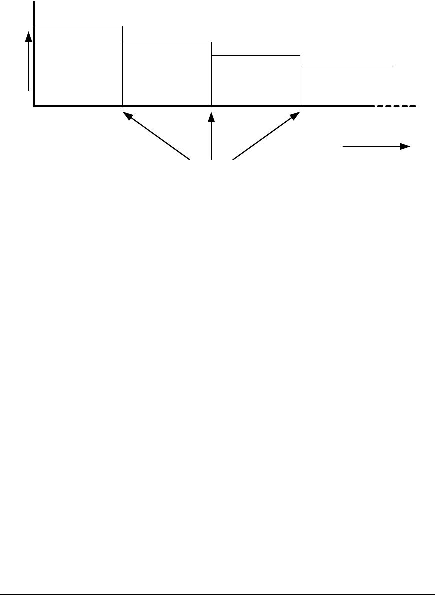
Block Tariff Power Switch Threshold Values
The meter is capable of operating a Block tariff where the price of electricity is changed
according to the usage from the start of the Billing Period.
Price/kWh
Block 1
Block 2
Block 3
Block4
Monthly Consumption
kWh
Power Switch
Threshold Values
The meter has the ability to hold three Power switch threshold values; these values represent
the value in kWh between blocks. The block tariff begins at the start of a billing period.
The meter stores $/kWh tariff values for each block shown above (see tariff matrix).
From the start of a billing period the total number of kWh’s or kWh’s consumed at current
TOU rate, are recorded. When the recorded value reaches a threshold value, the $/KWH
tariff will be changed according to the price defined for the next block.
Block four has no limit. When reaching block four the meter will continue to charge at the
block four rate until a new billing period is reached. If a threshold value is not entered then
the previous block will remain operative.
5 2 5 2 M E T E R F U N C T I O N A L I T Y U S E R M A N U A L
19
1919
19
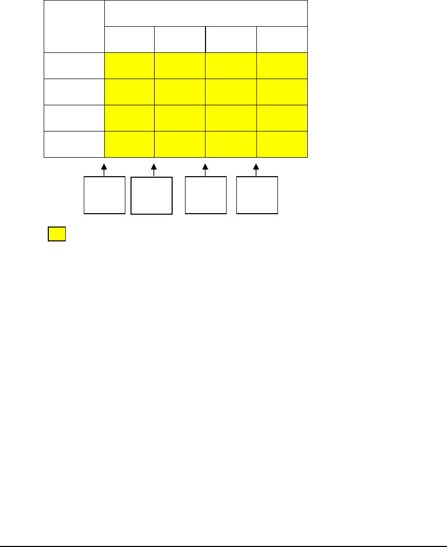
Tariff Plan
The rate at which the meter will charge can be automatically changed according to the
amount of power consumed over a fixed period. When using the power step tariff a set of $
per kWh prices are entered against consumption bands, the price altering once the power
consumed reached that kWh threshold value. The tariff prices applied by the meter can be
complied from: TOU tariff, Block tariff or a combination of both
The tariff will consist of a matrix of up to 16 prices as shown diagrammatically:
Step Tariff Power Bands Time
Of
Use Rates
Block 1
Block 2 Block3 Block4
Rate 1 1 2 3 4
Rate 2 5 6 7 8
Rate 3 9 10 11 12
Rate 4 13 14 15 16
Meter selects $
per kWh value
according the
time of use rate
and kWh
consumed
= Table of $/kWh charges
The $/kWh price has the range of 0-9999.99999
Block Tariff - Example
If a block tariff is configured, the meter will charge according to the usage during the month.
Initially the meter will charge the Block 1 $/kWh rate until the threshold x kWh’s is reached.
Upon reaching this threshold, the Block 2 $/kWh rate is applied and so on. A block tariff
will use prices 1, 2, 3 and 4 only.
Example - TOU Tariff
When operating a TOU tariff, the meter will adjust pricing according to the Time Switching
scheme set into the meter. If the meter is configured to switch to Rate 1 the meter will
charge for energy at price set against Rate1 in the matrix. A TOU only tariff will use prices 1,
5, 9 and 13 only
Combination tariff - Example
A Block and TOU tariff may be combined. As the meter switches rates according to the
Time switching plan the $/kWh charge dynamically changes according the Block tariff the
meter has switched to. A combination tariff can use any of the 16 pricing slots.
0
kWh
y
kWh
z
kWh
PS Threshold values
x
kWh
5 2 5 2 M E T E R F U N C T I O N A L I T Y U S E R M A N U A L
20
2020
20
Demand Response tariffs will operate as TOU only. A Demand Response command will
dynamically change the rate switching with energy recording and pricing switched to a
particular rate. A combination tariff could not be reconciled.
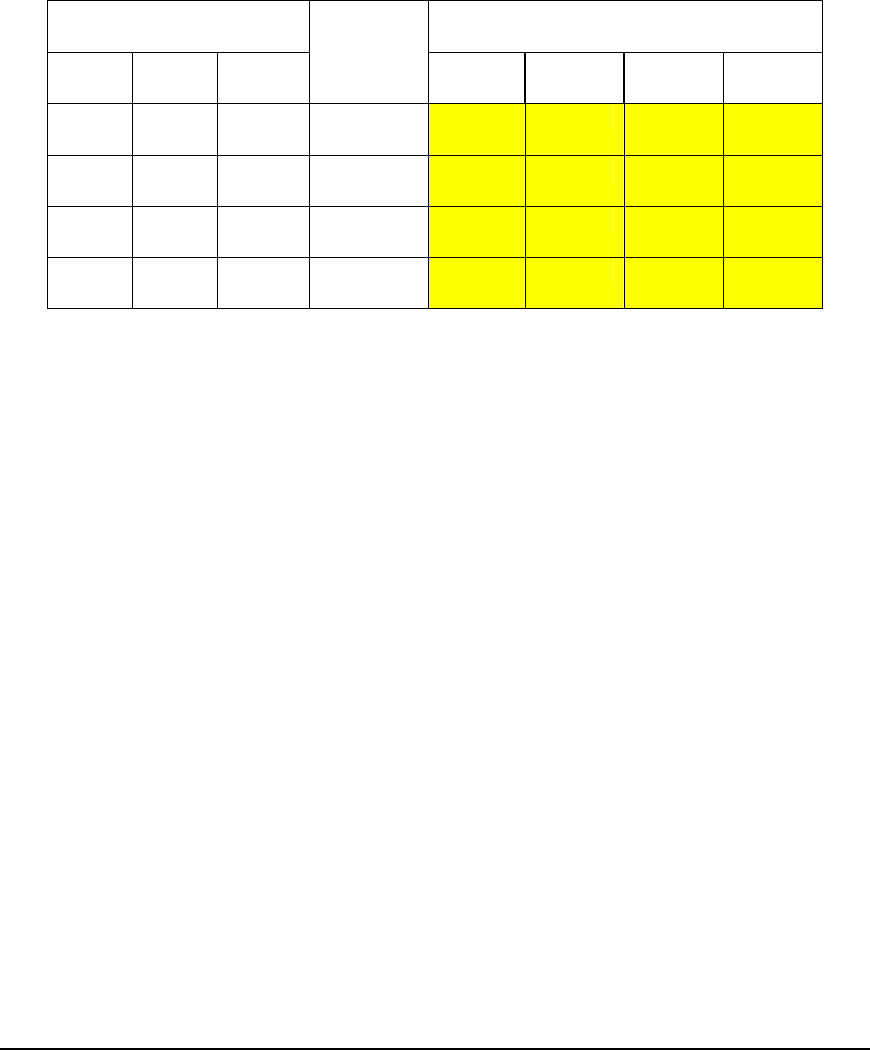
Demand Response Indication Assignment
In order to operate the DR indicators on the CIU a particular rate will be assigned a DR
indicator type in the Tariff Plan.
Enable DR Indicator Step Tariff Power Bands
Green
Ambe
r
Red
Time
Of
Use Rates
Block 1
Block 2 Block3 Block4
Rate 1 1 2 3 4
Rate 2 5 6 7 8
Rate 3 9 10 11 12
Rate 4 13 14 15 16
When the meter is switched to a particular rate the Enabled Demand Response indicator will
be lit on the CIU. This will operate whether the meter is in a normal Time switching plan or
whether the rate has dynamically changed according to a Demand Response command.
Example
Rate 1 is not configured, Rate 2 is assigned Green, Rate 3 Amber, and Rate 4 is assigned
Red.

5 2 5 2 M E T E R F U N C T I O N A L I T Y U S E R M A N U A L
21
2121
21
Meter Operation
Operational functionality for the 5252 Meter
Chapter
4
C O N T E N T S
Daylight Saving
Meter Test
Mode
Special
Contactor
Operation
Fixed Charges
Accountancy
Configuration
Credit
Transactions
Credit
Information
Log
Data logging
Emergency
Time Log
Self
Disconnects
Logging
Decommission
Data
Date / Time
Holidays

5 2 5 2 M E T E R F U N C T I O N A L I T Y U S E R M A N U A L
22
2222
22
Real Time Clock
The meter is fitted with a real time clock. The clock remains accurate by receiving time and
date updates by the Central System.
During periods of power failure an internal battery maintains the time and date. In battery
backed mode the accuracy is maintained to within ± {tba} minutes per year (at nominal
temperature)
The time display is shown in 24-hour mode. In standard operation the date is shown as
MMDDYY. Optionally the date may be displayed in an ISO standard format YYYY-MM-
DD (Canada)
The calendar used in the meter operates a standard Gregorian calendar and automatically
corrects for leap years.
The clock is configurable to operate all year without DST alteration or to switch
automatically for DST during the summer months.
Daylight Saving
Daylight saving is a programmable option. If enabled, the start and end values are
programmed: Month, Week (1, 2, 3, 4 or last), day, activation time (hours/minutes). The
time adjustment can be configured e.g. +/- 1hour.
When day light saving is activated the current maximum demand will be reset. The profile
log will indicate daylight saving by an indicator placed against the data.
Examples of setting day light saving
Month = 4: Week = 1: Day = Thursday activates on the 1st Thursday in April
Month = 4: Week = 2: Day = Friday activates on the 2nd Friday in April
Prepayment operation general
General prepayment operation is the same as the present 5211-meter with exception that
credit is transferred from the Central System rather than from the present smart card. When
credit is transferred to the meter which takes it out of debt and into credit, the contactor will
not close until the meter receives a wake up message from the CIU. For safety, this assumes
the customer is home. A $/kWh charge will be deducted each time a kWh is recorded in the
active rate register.
Holidays
The meter can be programmed with up to 15 configurable Holiday Dates for the purpose of
‘friendly no disconnect periods’ and for the support of holiday kWh charges.
The tariff that the Holiday Dates will operate in can be defined from the available rate tariffs
1 -4 if configured. If only one tariff exists then the Holiday Dates are set to operate using the
default tariff. As the holiday dates may vary from year to year, the utility will have to update
the dates via the AMS / smart card.
5 2 5 2 M E T E R F U N C T I O N A L I T Y U S E R M A N U A L
23
2323
23
Seasonal Non Disconnect
Seasonal Non Disconnect will operate between a configurable start and end date/time. The
period of time between the dates means the meter will not disconnect even if credit has
expired. The time configuration ensures the meter connects/disconnects at a friendly time.
If the meter was disconnected before the start date the meter will remain disconnected.
If prepaid energy reaches zero during the no-disconnect period the credit register will
continue to record energy usage as a debt. If the meter’s credit balance is negative at the end
date/time the meter will automatically disconnect.
Friendly Non-disconnect
The meter offers a facility to prevent disconnection of the contactor when prepaid credit
falls below zero. Each day type (Mon to Sun) will be programmed with a start and end time
for the friendly zone. Friendly zones may differ on each day.
If prepaid credit reaches zero during a friendly period the contactor will open when the end
time of the zone is reached
The ‘friendly’ periods can be set either by the factory or configured by the Field Unit
Software or via the AMPY Management System /Central System
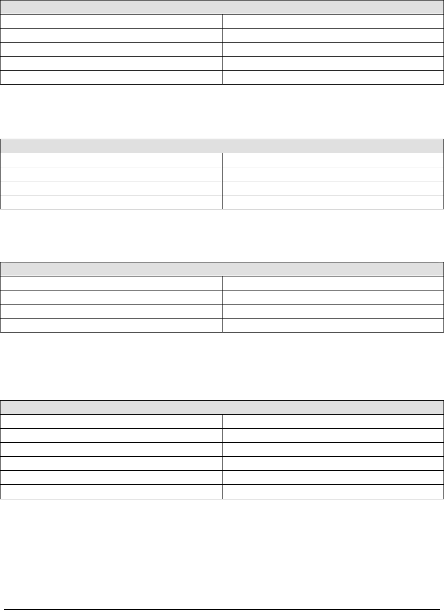
Possible configuration options for Friendly Non-Disconnect Settings
Weekday Start Time
End Time Friendly All Day Not Configured
Monday HH:MM HH:MM
Tuesday HH:MM HH:MM
Wednesday HH:MM HH:MM
Thursday HH:MM HH:MM
Friday HH:MM HH:MM
Saturday HH:MM HH:MM
Sunday HH:MM HH:MM
Tariff Storage
The meter stores two sets of tariff data active and future. The future tariff (if available) will
come into force on its activation date (see data logging).
Fixed Charges
The meter can store two sets of fixed charges data for active and future. The future charge
will come into force on its activation date. Future dates may be used to implement summer
and winter seasons.
Fixed Charges are collected every 1/100
th
of a week. This ensures the maximum amount the
credit register decrements in reasonably sized amounts. The meter has 2 registers that can be
set independently to recovery fixed charges.
5 2 5 2 M E T E R F U N C T I O N A L I T Y U S E R M A N U A L
24
2424
24
Fixed charges can be configured to collect charges whilst the meter is disconnected.
Configuration example:
Field Name Type Active Date
SC1 Fixed Fee Total Active None
SC1 Fixed Fee Total Future June 30 2002
SC2 Budget Billing Active None
SC2 Budget Billing Future June 15 2002
The Fixed Charges registers have a range 0000.00 – $9999.999
Accountancy Configuration
The maximum credit value will be $9999.99 and minimum $0.01
The maximum kWh rate will be $9999.99999 and minimum $0.00000
Credit Transactions
The meter will hold the last 100 credit transaction ID’s in a rolling buffer, the last 5 credit
transaction ID’s are always returned on the smart card. The Management System knows the
credit transaction IDs assigned to each card.
Credit Information Log
The meter will hold a rolling record of last 16 transactions that been seen in the meter, and
will store information for the credit value, credit Id, Status and time stamp for each record.
An entry pointer flag denotes the last recorded transaction.
Demand Response
The meter is able to offer variable pricing to the customer using the TOU rates, which can
be switched outside of the preset rate plan by a command from the Central System.
The meter will respond by overriding the normal rate-switching plan and switching to a
defined rate between a start and end time and date.
The Demand Response command is defined as
:
Date Time
Start MM.DD.YY
HH:MM
End MM.DD.YY
HH:MM
Switch to Rate 1 to 4
The meter has the ability to store 2 demand response commands as described above.
Upon reaching the start time of the command the meter will switch to the defined rate and
record any energy consumed after the start date into the defined rate register.
5 2 5 2 M E T E R F U N C T I O N A L I T Y U S E R M A N U A L
25
2525
25
Upon reaching the end time of the command the meter will revert back to the normal rate-
switching plan
While the meter is in a Demand Response period, prepay customers will be charged at the
defined $/kWh rate. The CIU will reflect the change in rate and tariff by updating ‘Rate x
charge is $x.xx’ display to the defined $/kWh rate.
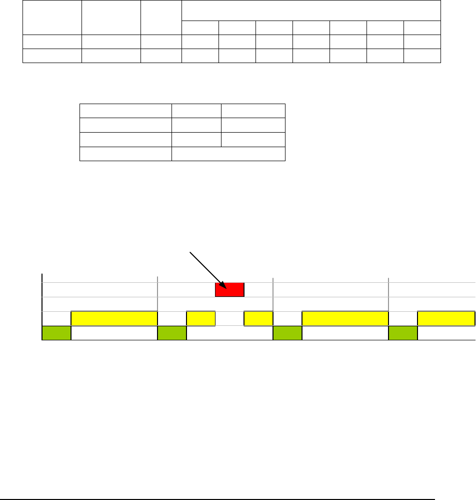
Example:
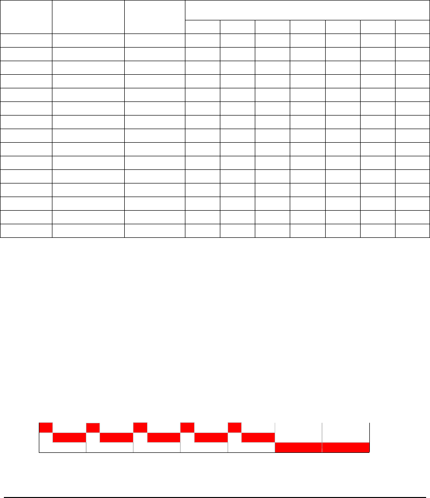
The following scenario shows the rate switching of the meter when a Demand Response
command is received. The example shows the start of the January 2006 for 4 days.
The meter is configured to run a TOU Rate switching plan as follows:
Enabled switching days Time
Switch
Start
Time Rate Mon Tue Wed Thru
Fri Sat Sun
1 00:00 1
2 07:00 2
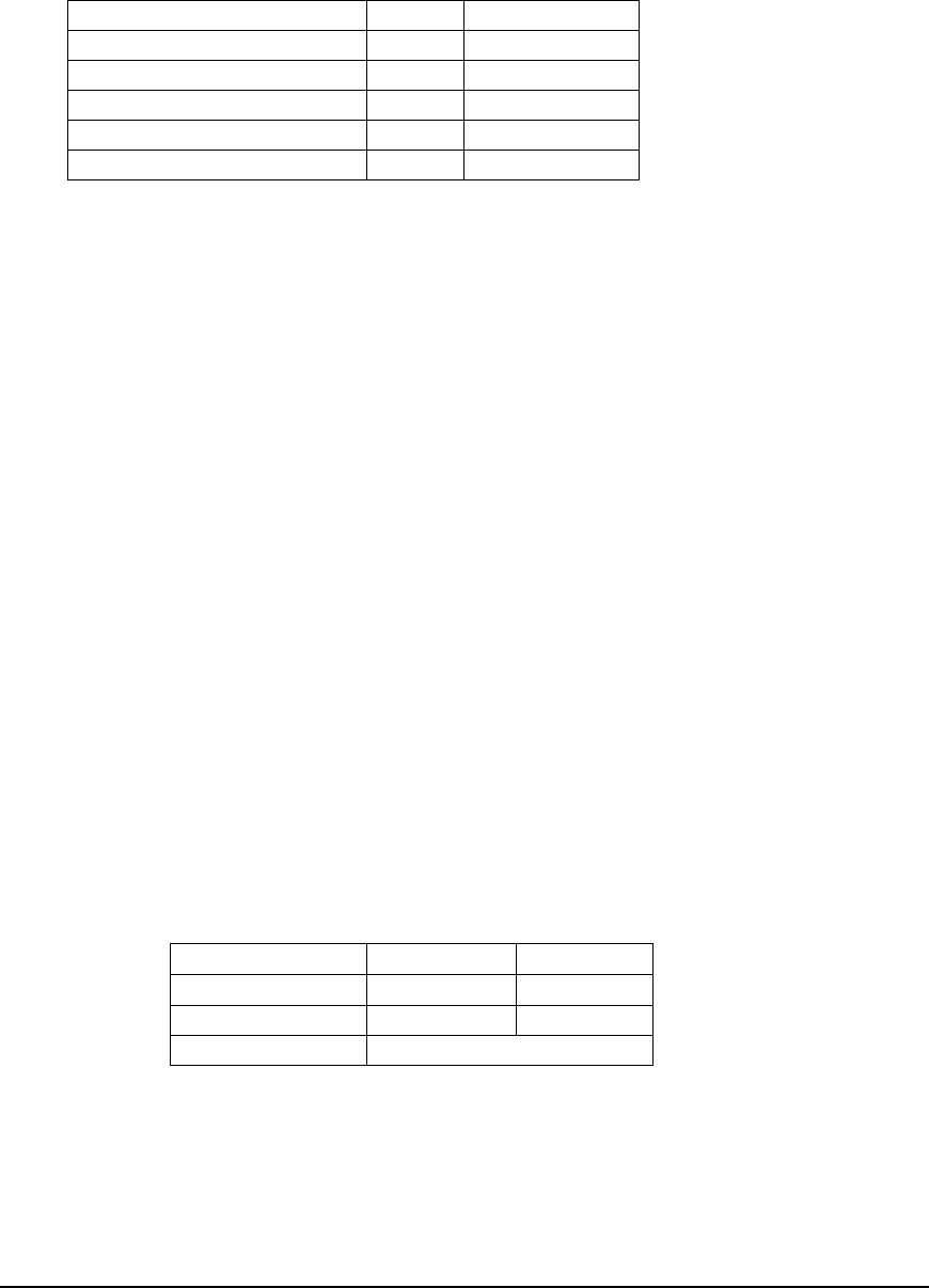
A Demand Response command is sent to the meter with the following parameters –
Date Time
Start 01.02.06
12:00
End 01.02.06
18:00
Switch to Rate 4
The Demand Response command would have the rate switching effect on the meter:
R4
R3
R2
R1
MON 1st TUES 2nd WED 3rd THURS 4th
DR Command Executed
Parameters:
Start 2.1.06 12:00
End 2.1.06 18:00
Switch to Rate 4
On Tuesday 2nd the normal rate switching plan would be suspended. The Demand
Response command would override the normal TOU plan. Any energy consumed between
12:00 and 18:00 would be recorded in the R4 register. Prepay customers will be charged at
the appropriate $/kWh rate with the CIU showing the $/kWh rate. The CIU will indicate
Demand Response LED’s according to TOU rate applied.

5 2 5 2 M E T E R F U N C T I O N A L I T Y U S E R M A N U A L
26
2626
26
Remote Disconnect/Reconnect
When operating in credit mode the meter may be issued a command via the Central System
to open the meters contactor. Upon receipt of such command the contactor will open and
remain open, the metrology indicator on the display will not be shown. The command may
be accompanied by an ad-hoc read request in the case of changes in tenancy.
Reconnection of supply will be made following a command from the Central System. A
‘System Initiated Closure’ command will close the contactor upon receipt of the request
without any further customer action. This assumes the utility knows the customer is present
at the installation or that the installation is safe for reconnection.
In some cases reconnection of supply will be offered to the customer following a command
from the Central System. A ‘Customer Initiated Closure’ command will offer the customer
the ability to close the contactor using the CIU unit. In this case, when a wake up message is
sent from the CIU the meter will use this as a signal to restore supply. This mode will allow
the utility to send a reconnect command without knowing whether the customer is present;
the customer effectively reconnects his own supply. Following a ‘Customer Initiated Closure’
command the CIU will be instructed to display a supply-reconnected message
Safety Reconnection
The meter will ensure that the customer does not have a secondary supply connected (own
generator etc.) when reconnecting supply.
The meter is fitted with a detection circuit connected across the customer load side of the
contactor to check for voltage present at the time of switch closure.
If the meter receives either a ‘system’ or ‘customer initiated’ closure the meter will check the
voltage on the customer supply side of the open contactor, prior to closure. If voltage is not
considered present the meter will close the contactor (provided customer has chosen to
close contactor in case of customer initiated closure).
If the detection circuit detects the presence of external supply voltage the contactor will not
close and the closure command will be returned with an error.
Meter Test Mode (Metrology Testing)
The meter can be programmed into a test mode to allow accuracy tests to be performed. All
accountancy will be frozen and a separate test mode register used to accumulate power
throughout the test.
The test mode register will always be zero when switched into test mode. When the meter is
disconnected and re-powered or reprogrammed out of test mode the accountancy will
restart.
Field Test Mode
This operation can also be used in the field using an option called Field Test Mode. This
allows a field operative to remove a customer meter from the wall, perform a metrology test,
and then replace it back on the wall. The Meter will revert to normal operation after two
Power-ups or after a 60 minutes safety period (the contactor will revert back to its original
state prior to the operation).

5 2 5 2 M E T E R F U N C T I O N A L I T Y U S E R M A N U A L
27
2727
27
Profiling
The meter will record a profile of 15-minute interval kWh readings. Hourly or half hourly
profiles are obtained by summation of profiles in the Central System. Up to 50 days of the
most recent profiles will be stored within the meter, if the profiles are not down loaded
within 50 days the oldest reading will be over written with the most recent. Each profile
consists of the advance Wh’s since the previous 15 minutes profile.
During power fail the missing kWh readings will be padded to maintain a sequential log. If
the meter is disconnected for more than three days, the whole log will be cleared.
When day light saving is activated the profile log will indicate daylight saving by an indicator
placed against the data.
Maximum Demand
Active power is integrated over a configurable period of 1,2,3,4,5,6,10,12,15,20,30 or 60
minutes. The maximum demand value is calculated at the end of each period, the highest
demand value is stored complete with time stamp information.
Demand periods will be synchronized to the hour. For example, if the interval is 15 minutes,
the starting times are 10:00, 10:15, 10:30 etc.
The meter will record maximum demand values into one of 4 MD registers (MD1 to 4).
Each MD register will be active according to the configured TOU rates i.e. if TOU rate 2 is
active MD 2 register will be active.
At the end of each day (00:00) the meter will record the four MD registers into a rolling log.
The rolling log will contain the last 3 days of MD recordings. On storage of a new set of
recordings the earliest set will be pushed out. At the same time the meter will reset the
running MD registers 1-4.
Energy Registration
An infrared LED is mounted on the front of the meter, pulsing at a rate proportional to the
measured load. The pulse value is identified on the meters fascia. The pulse can be used for
checking the meter calibration and will illuminate continually to indicate no load (Anti
Creep), with further information presented on the cycling display.
Tamper Detection
The meter is fitted with a tilt detection switch to detect removal of the meter from its base.
Any triggering of the tamper switch is reported via status collection from the meter.
Visually the tamper flag will be shown on the display.
Optionally the meter may be configured to open the main contactor.
Resetting of the tamper flag/supply reconnection can be achieved by system command or
using the meter optical port.
Optionally the tamper detection feature can be disabled

5 2 5 2 M E T E R F U N C T I O N A L I T Y U S E R M A N U A L
28
2828
28
Power Outage Reporting
The meter holds a rolling log containing the last 5 reported outages. Each log entry will
consist of a time and date stamp of the outage plus the reconnection time and date stamp.
The log will be held as follows:
Occurrence
Supply ON
Date /Time
Supply OFF
Date/Time
1
2
3
4
5
Special Contactor Operation
A mode is available to test the meter in environments where there is insufficient supply to
fire the contactor. This mode can be used to test meters using RFL5800 and UTEC 620 test
machines.
The meter can be configured not to reaffirm the contactor position during testing by special
command.
The meter will revert back to its previous state after two power ups or after one hour has
elapsed.
A pre-condition with this operation is that the contactor is already closed.
Note: Once the contactor has been changed the meter will not attempt to operate
the contactor for 60 seconds following the power-up. Whilst in this mode the
contactor will not be periodically reinforced.
Data Logging
At the end of each month and on the tariff activation date the meter will store the 4 kWh
rate registers, tariff identifier and date. The meter will store a rolling 6 months of kWh usage
data for the 4 kWh rates in a rolling buffer. The oldest month’s data will be overwritten with
the most recent month’s data. The tariff update registers will be overwritten on the next
tariff update.
NOTE: The average daily kWh for any month can be calculated by dividing the
monthly consumption by the number of days in the month (performed by the
AMPY Management System).
Each credit transaction is logged for accounting purposes.
5 2 5 2 M E T E R F U N C T I O N A L I T Y U S E R M A N U A L
29
2929
29
Emergency Time Log
The meter will hold the last five values for when an emergency code has been received by
the meter. The meter will store whether the emergency code entered was either a 24 hour E-
Code or a 7 day E-code. An entry pointer flag denotes the last recorded emergency time.
To calculate the number of days recorded in the log number of minutes should be divided
by the number of minutes in a day (1440) and roundup the value to the nearest day.
NOTE: This will allow the FUS to enter an e-code other that 1 and 7 days
The log will record the following details depending on the minutes entered:
Emergency Minutes Record In Log (days)
1440 1
4320 3
10080 7
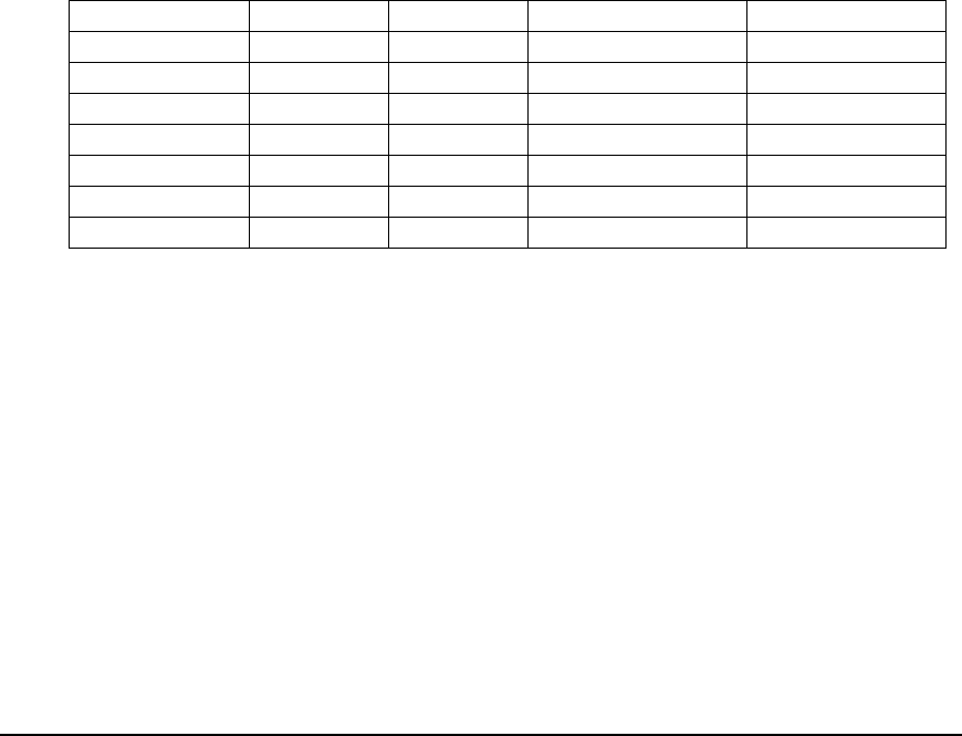
Self Disconnects Logging
The meter will hold the last five disconnect and reconnection date pairs. The disconnect
time and date will be recorded when the contactors opens. The reconnection time and date
will be recorded when the contactor closes.
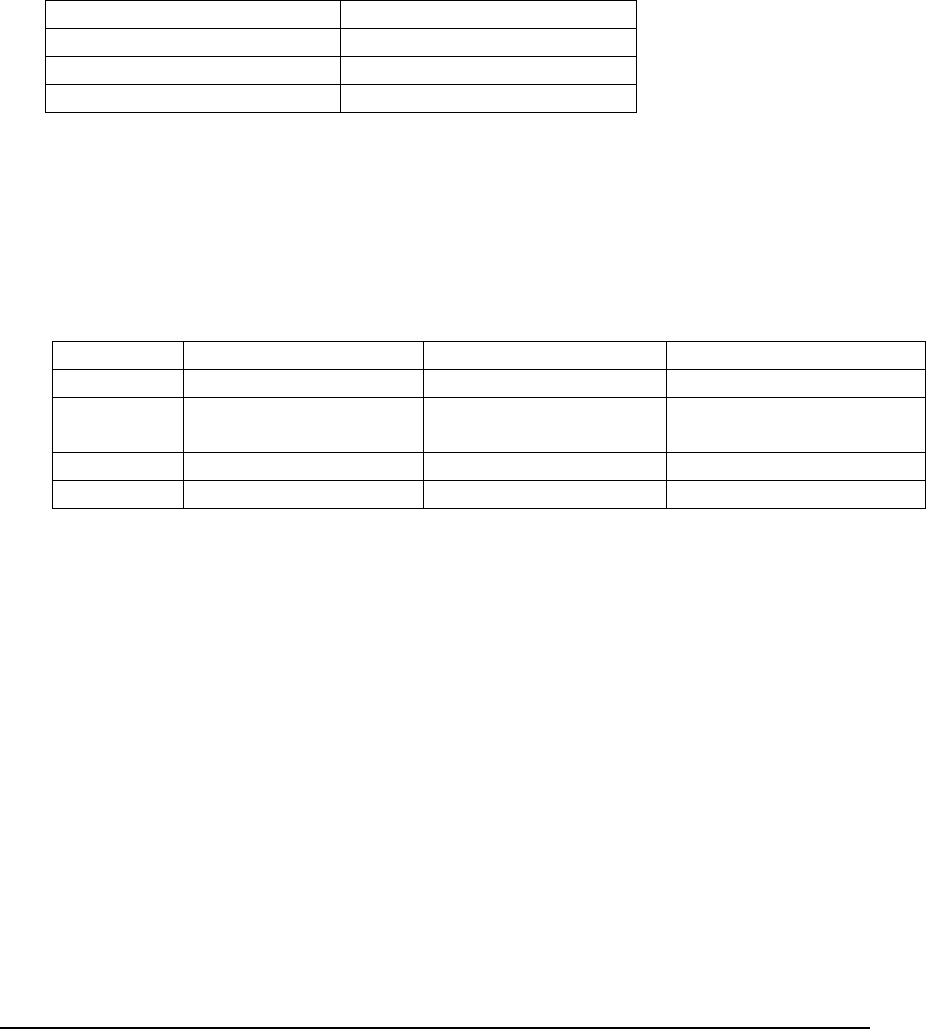
Example
Log Entry Disconnect Date Reconnect Date Description
1 1-1-2006 10:34:34 20-1-2006 09:00:02 Complete entry
2 28-2-2006 03:23:23 1-1-1970 00:00:00 Part entry: No reconnect
date
….. 1-1-1970 00:00:00 1-1-1970 00:00:00 No date logged
5 1-1-1970 00:00:00 1-1-1970 00:00:00 No date logged
Decommission / Re-commission Data
The meter is able to cope with changes in tenancy to the installed property by a
Decommission Command.
A decommission command can be configured in advance; the Central System will
accompany a decommission command with an activation date and time for when the
process should occur. The meter will only perform the operation at the configured date and
time.
A decommission command will have the following configurable parameters, including:
Reset or overwrite Credit register, configurable from 0 to maximum top-up value (if in
prepay mode)
Clear credit transaction log
Option to open meters contactor

5 2 5 2 M E T E R F U N C T I O N A L I T Y U S E R M A N U A L
30
3030
30
The decommission command will trigger a Snapshot of readings. Registers to be read and
sent to the CS will include:
All kWh registers
Maximum Demand registers
Value of Credit register prior to Decommission (if in prepay mode)
Snapshot will be time and date stamped
Re-commissioning will follow a Decommission. The Central System will send any new tariff
settings including new tariff plans, TOU switch settings and a Contactor closure command
(If required). At Re-commission the meter will also be sent a new Credit Register value (if
not set by the decommission command). All re-commission commands will have an
activation date.

5 2 5 2 M E T E R F U N C T I O N A L I T Y U S E R M A N U A L
31
3131
31
Meter Registers
Meter Registers for the 5252 Meter
Chapter
5
C O N T E N T S
Credit/debit Register
Maximum Credit Register
Accountancy
Configuration
Decimal Point
Configuration
Maximum Demand
period
Active Register
kWh Register
$ Per Unit for Rates 1 – 4
Usage yesterday
$ Usage Per Hour
KW Usage Per Hour
$Usage
Today/Month/Last
Mont
Active Fixed Charge 1
and 2
Future Fixed Charge 1
and 2/Activation Date
Seasonal non Disconnect
Start and End
Date/Time
Operation Mode
Power Fail Count
Wake up Register
Credit Transfer Register
Credit History
Credit Information Log
Friendly Debt Register
Energy registration
Modes
Voltage Reporting

5 2 5 2 M E T E R F U N C T I O N A L I T Y U S E R M A N U A L
32
3232
32
Credit/Debt Register
The Credit/Debt register is settable in the range $-9999.99 to +$9999.99. All electricity
consumptions are collected from this register as well as ancillary charges such as fixed
charges and debt collection. At reaching the maximum credit, configurable via smart card,
card will not be accepted.
This register can be reset to zero using the AMPY Field Unit Software.
Maximum Credit Register
The maximum credit register is settable in the ranger $-9999.99 to +$9999.99.
Accountancy Configuration
The maximum credit value for the meter is $9999.99 with a minimum value of $0.01
The maximum kWh rate for the meter is $9999.99999 with a minimum value of $0.00000
Decimal Point Configuration
The decimal point configuration is applicable to the following registers:
Total kWh
Rx Registers (x= rate 1 to 4)
Configurable options 0, 1 or 2dp.
Maximum Demand Period
This registers configures the sampling period for logging the maximum demand.
Configurable options 1,2,3,4,5,6,10,12,15,20,30 or 60 minutes.
Active Rate
This register indicates the current active chargeable rate for kWh units.
kWh Registers
The Total kWh register and kWh registers for time of use rates 1 to 4 can be read. Each
register has a field size of 00000.01 to 9999999.99 kWh.
The four kWh rate registers and total kWh register can be reset to zero using the AMPY
Field Unit software.
$ Per Unit for Rates 1 TO 4
The rate per kWh unit for each of the four TOU rates, are settable in the range of $0.00000
to $9999.99999.
Usage Yesterday
The usage yesterday stores the previous days consumption in $ values. This is calculated on
all charges normally applied within a 24 hour period and is settable in the range $0.01
to$9999.99.

5 2 5 2 M E T E R F U N C T I O N A L I T Y U S E R M A N U A L
33
3333
33
$ Usage per Hour
The usage register stores information, in real time, on consumption in $ values. This is
calculated on all charges normally applied within the last hour and is displayed from $0.01 to
$9999.99. The register is calculated on a three second average.
KW Usage per Hour
The kW usage per hour register stores information, in real time, on the consumption in kW
per hour. The register is calculated on a three second average.
$ Usage Today
This register stores the actual $ cost for the current day and includes all normal charges. The
register is updated whenever the main credit register is adjusted and is displayed from $0.01
to $9999.99
$ Usage This Month
This register stores the actual $ cost for the current month and includes all normal charges.
The register is updated whenever the main credit register is adjusted and is displayed from
$0.01 to $9999.99.
$ Usage Last Month
This register stores the actual $ cost for the previous month and is displayed from $0.01 to
$9999.99.
Active Fixed Charge 1 and 2
The two registers store the active values for the charge 1 and 2. Charges are collected every
1/100
th
of a week. The registers have a range 0000.00 – $9999.999.
Future Fixed Charge 1 and 2
The two registers store the future values for the charge 1 and 2. The registers have a range
0000.00 – $9999.999.
Future Fixed Charge 1 and 2 Activation Dates
The two registers store the dates in seconds from 1/1/1970 that the future fixed charges will
be applied to active fixed charges registers.
Seasonal Non Disconnect Start and End Date/Time
The two registers stores the date and time the meter will not disconnect/disconnect.
Operation Mode
The operation mode stores the meter configuration. The meter has two operation modes,
pre-payment or credit.

5 2 5 2 M E T E R F U N C T I O N A L I T Y U S E R M A N U A L
34
3434
34
Power Fail Count
This register stores the total number of power fails occurrences. The register has a range of 0
to 255.
Wake Up Register
This register stores the number of wake up messages sent to the meter, details are recorded
in a rolling record for 10 entries and a counter will register up to ‘255 wake up’ attempts.
This information can be retrieved using the AMPY Field Unit Software.
Credit Transfer Register
This register contains details for the last 10 transactions that have been seen by the meter,
detailing time and date record, credit value /ID, and status.
Credit History
The meter holds the last 100 and the last 5 credit transactions in a rolling buffer. The log
records the Credit ID information
Credit Information (Transfer) Log
The meter holds a rolling record of last 16 transactions that been seen in the meter, and logs
the following information for the credit value: Date/Time, Credit ID, Value and Status
An entry pointer flag denotes the last recorded transaction.
Friendly Debt Register
The friendly debt register ensures that wake up messages can not be used to invoke a
configured friendly period when the accumulated debt in the meter is greater than the
friendly debt level.
This principle is also used when a credit amount is added which is not greater than the limit
set in the friendly debt register, or if a wake up is invoked using both buttons of the
Customer Information Unit. This information can be retrieved using the AMPY Field Unit
Software.
NOTE: If the friendly debt register is greater than the accumulated debt in the meter,
and an E-Code is successfully accepted by the meter, then the contactor will remain
closed during the entered emergency period.
Possible scenario explanations:
Example 1
Friendly Debt Value is configured to $- 5.00
Customer balance (accumulated debt) $- 3.00
Customer presses both buttons on the CIU within 10 minutes of a friendly period start time,
or during a friendly period. The meter will remain connected for the duration of the friendly
period.

5 2 5 2 M E T E R F U N C T I O N A L I T Y U S E R M A N U A L
35
3535
35
Example 2
Friendly Debt Value is configured to $- 5.00
Customer balance (accumulated debt) $- 6.00
Customer presses both buttons on the CIU within 10 minutes of a friendly period start time,
or during a friendly period. The customer can have up to 5 wake up attempts per day, but
after the 10 minute period the meter will disconnect. The meter will not connect for the
duration of the friendly period
.
Energy Registration Modes
The meter has the ability to register energy in one of three different modes, Cumulative,
Detent or Net. In addition the meter will record all Received energy into a separate register.
When configured to operate in one of the modes listed, the meter will accumulate energy
into the Active Rate and Total Registers (Delivered energy registers) as follows:
Cumulative (Sum) kWh
When operating in Cumulative mode, any Received energy (Export/Reverse energy)
recorded by the meter is added to the Active Rate register and ultimately to the Total Energy
Register. In this mode, should the meter be removed and refitted upside down, the utility is
protected against energy theft.
Example
If 5 kWh were recorded forward (Delivered) through the meter then 2 kWh reverse
(Received) through the meter the energy registers would read:
Active Rate Register 7 kWh
Reverse (Received) register 2 kWh
Detent (Delivered) kWh
In Detent mode, Received energy recorded by the meter has no effect on the Active Rate
register of the meter. The meter acts as if it is fitted with a reverse stop.
Example
If 5 kWh were recorded forward (Delivered) through the meter then 2 kWh reverse
(Received) through the meter the energy registers would read:
Active Rate Register 5 kWh
Reverse (Received) register 2 kWh
Net kWh
With Net registration, Received energy recorded by the meter is subtracted from the active
rate register and ultimately the Total Energy registers.
Example
If 5 kWh were recorded forward (Delivered) through the meter then 2 kWh reverse
(Received) through the meter the energy registers would read:
Active Rate Register 3 kWh

5 2 5 2 M E T E R F U N C T I O N A L I T Y U S E R M A N U A L
36
3636
36
Reverse (Received) register 2 kWh
Delivered (Export/Reverse) register
Any received energy is separately recorded in the Received Energy register. This register will
record the total received energy. The display layout is shown in the display section.
It should be noted that the meter will not operate in Net mode when selected for prepay
operation.
Voltage Reporting
The meter measures and records the voltage present at the meter for reporting purposes.
The meter records the maximum and minimum voltage measured over a 1-day period. The
meter holds a rolling log of the last 3 days max/min voltages.
The instantaneous voltage present at the meter is also available by performing an ad hoc
enquiry to the meter.

5 2 5 2 M E T E R F U N C T I O N A L I T Y U S E R M A N U A L
37
3737
37
Communication
Communication Properties for the 5252 Meter
Chapter
6
C O N T E N T S
Periodic Daily
Reads
Periodic
Monthly Reads
Periodic Time
Update
Periodic Load
Profile
Collection
Instantaneous
Power Outage
Reporting
Instantaneous
Read Request
Instantaneous
Disconnect
/Reconnect
Request
Instantaneous
Prepay
Transaction
Instantaneous
Request –
Config Update
Global
Broadcast –
Demand
Response

5 2 5 2 M E T E R F U N C T I O N A L I T Y U S E R M A N U A L
38
3838
38
Periodic - Daily Reads
The system will schedule a daily read from the meter.
Each daily read will consist of:
Rate 1 kWh register
Rate 2 kWh register
Rate 3 kWh register
Rate 4 kWh register
Prepayment Credit level
Last 5 Credit ID’s received
Status Information (includes tamper detection).
Daily register and credit level reading will be transmitted as a snap shot taken at 00:00
Periodic - Monthly Reads
A read of additional information is collected once per month. The read is scheduled by the
Central System and read from the meter between the 1st through to the 28th of the month
Maximum Demand registers
KWh Registers (In cases of monthly reads only or failed daily read)
Self-Disconnect Log (Date/Time contactor opened/closed not balance <0 and >0)
Emergency time Log
Credit Log
The Maximum demand registers sent are those previously stored at the end of the billing
period.
Periodic - Time Update
Time is updated by the Central System using a global broadcast
Time held by the meter must be kept accurate and within limits stated in performance
requirements
Periodic - Load Profile collection
Load profiles will be collected from the meter by the CS. Collection will be part of a
scheduled task. Where Load profiling information is not required then the profile
information is not collected by the system.
Each individual profile will be transmitted as the advance in kWh’s since the previous
profile. The set of profiles will be transmitted in a way that will allow time and date stamping
of each individual profile.

5 2 5 2 M E T E R F U N C T I O N A L I T Y U S E R M A N U A L
39
3939
39
Instantaneous - Power Outage reporting
When the meter detects a loss of supply that is of sufficient length to be considered a power
outage (see electrical parameters) a message is reported to the CS system before the meter
and OS module’s stored power is depleted.
The outage message will consist of a the meters serial number and a message identifier {tba}
Instantaneous - Read request
A priority request will be sent by the CS to the meter at any time to return the following:
Rate 1 kWh register
Rate 2 kWh register
Rate 3 kWh register
Rate 4 kWh register
Prepayment Credit level
Last 5 Credit transaction details received { # of ID to be agreed}
Status Information, including tamper detection
Instantaneous - Disconnect/Reconnect request
When operating in a credit mode a request Disconnect Message sent from the CS will
instruct the meter to open its contactor.
Two types of closure commands will determine how the contactor is re-closed:
A ‘System Initiated Closure’ command will instruct the meter to close the contactor
directly
A ‘Customer Initiated Closure’ command will allow the customer to reconnect power
using the connected CIU.
Instantaneous – Prepay Transaction
When operating in prepay mode the CS will send a Prepay transaction to top up the credit in
the meter. A prepay transaction will comprise of payment value and a transaction identifier.
Instantaneous Request – Config Update
Meter shall be able to be reconfigured by a message sent from the CS. Reconfigurable items
shall include
Current/Future Tariff Rate Plan (including time switches)
Current/Future Fixed Fees
Operating mode Credit/Prepay
Resetting of tamper flags
Friendly Non-Disconnect Hours
Seasonal Non-Disconnect
CIU configuration Data (including Display lists)
Meter configuration Data (including Display lists, DST etc.)
Holiday dates

5 2 5 2 M E T E R F U N C T I O N A L I T Y U S E R M A N U A L
40
4040
40
Global Broadcast – Demand Response
To allow variable pricing to the customer the CS will send a global demand response
message all meters. The message will consist of a start time and date, end time and date and
the rate to which the meter will switch. Although the message is a global broadcast, the
message will be acknowledged by the meter so that the CS can ensure all meters have
received the broadcast.

5 2 5 2 M E T E R F U N C T I O N A L I T Y U S E R M A N U A L
41
4141
41
Definitions
ANSI American National Standards Institute
DR Demand Response
CIU Customer Information Unit
kWh Kilo Watt-hours
LCD Liquid Crystal Display
LED Light Emitting Diode
CS Communications System
RTC Real Time Clock
mS Milli-sceond
GMT Greenwich Mean Time – equals UTC (Universal Time Coordinated)
AMS Ampy Management System