AmRoad Technology RF221 RF MODULE User Manual RFID Description of Operation
Amroad Technology Inc. RF MODULE RFID Description of Operation
Users Manual
RF MODULE Users Manal
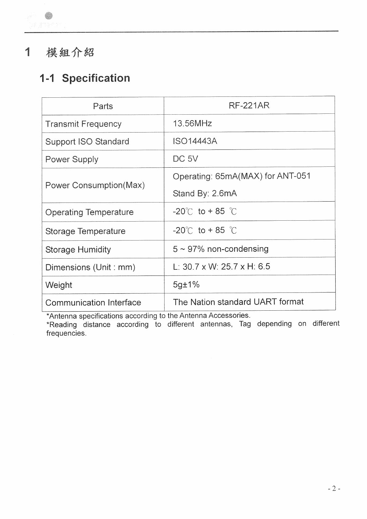
trademark: amroad model: RF-221
The RFID part is an ISO 14443A RFID reader/writer, It’s operating in the 13.56MHz
ISM (Industrial Scientific Medicine) band for ISO 14443A RFID system.
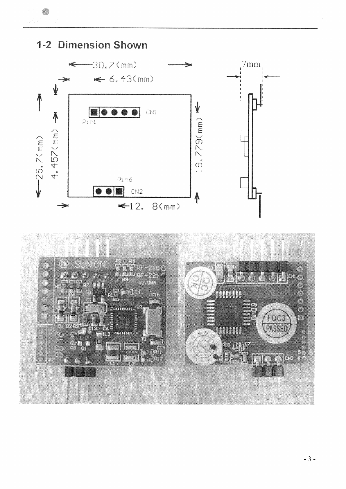
The circuit is comprised of a Micro Controller unit(MCU), 13.56MHz RF Transceiver
circuit and aLOOP Antenna.
Micro Controller Unit(MCU)
The Control circuit controls all of RFID ASIC signals.
Control circuit outputs the command data which is needed to work the Transceiver
circuit. When the response data from the RFID ASIC circuit, it will proceed
recognition and other procedure.
RF Transceiver circuit (RFID ASIC).
The signal of 13.56MHz is supplied from crystal oscillator.
The Magnetic field signal is generated by the Transceiver circuit.
This ASK modulation signal is supplied through the Impedance transformer and the
Antenna matching circuit to the externalLOOP Antenna.
The feedback signal sent from the tag is received at theLOOP Antenna and is input to
The H.P.F. The signal is demodulated by the RF ASIC .
LOOP Antenna
The external LOOP Antenna is formed with the coil, and supplies the electric power
and the transmission signal to the tag by generating the flux of magnetic field
The product can only be installed in the device which the model name conforms to the
following wildcard characters : AABBBXR-YY-ZZ , and it must be installed by professionals. The
host end product must also pass the FCC Part 15 unintentional emission testing requirement
and be properly authorized per FCC Part 15.
The instruction for series models of DB3101R-FM-BA as below :
AABBBXR-YY-ZZ
A - Application
B - Number
X - Version
R - RFID
Y - Installation
Z - Color
For example : DB3101R-FM-BA
§ P15.21
Any changes or modifications not expressly approved by the party responsible for compliance could void
your authority to operate the equipment.
§ P15.19
This device complies with part 15 of the FCC Rules. Operation is subject to the following two conditions:
(1) This device may not cause harmful interference, and
(2) this device must accept any interference received, including interference that may cause undesired
operation.
§ P15.105
Note: This equipment has been tested and found to comply with the limits for a Class B digital device,
pursuant to part 15 of the FCC Rules. These limits are designed to provide reasonable protection against
harmful interference in a residential installation. This equipment generates, uses and can radiate radio
frequency energy and, if not installed and used in accordance with the instructions, may cause harmful
interference to radio communications. However, there is no guarantee that interference will not occur in a
particular installation. If this equipment does cause harmful interference to radio or television reception,
which can be determined by turning the equipment off and on, the user is encouraged to try to correct the
interference by one or more of the following measures:
—Reorient or relocate the receiving antenna.
—Increase the separation between the equipment and receiver.
—Connect the equipment into an outlet on a circuit different from that to which the receiver is connected.
—Consult the dealer or an experienced radio/TV technician for help.
§ Restrictive module warning
Declaration the Restriction of this Limited Module Approval:
According to FCC Part 15 Subpart C Section 15.212, the radio elements of the modular transmitter must
have their own shielding. However, due to there is no shielding for this module, this module is granted as a
Limited Modular Approval. When this Wireless Module is installed into the end product, a Class II
Permissive Change or a New FCC ID submission is required to ensure the full compliance of FCC relevant
requirements.