Anchor Audio WM-900 WingMAN User Manual WingManManual oct07 indd
Anchor Audio Inc WingMAN WingManManual oct07 indd
Users Manual
A MESSAGE FROM THE OWNER
Thank you for choosing an Anchor Audio intercom system. Our products incorporate state-of-the-art
design and the finest quality of materials and workmanship. We’re proud of our products and appre-
ciate the confidence which you have shown by selecting an Anchor system.
I hope you’ll take a few minutes to review this manual. We’ve incorporated several unique features
into our products, and your knowledge of how to use them will enhance the performance and your
enjoyment of the system.
Janet Jacobs – President
on behalf of all Anchor Employees
Anchor Audio, Inc.
Portable Sound Systems • Torrance, California 100-0165-000/A - 10/07
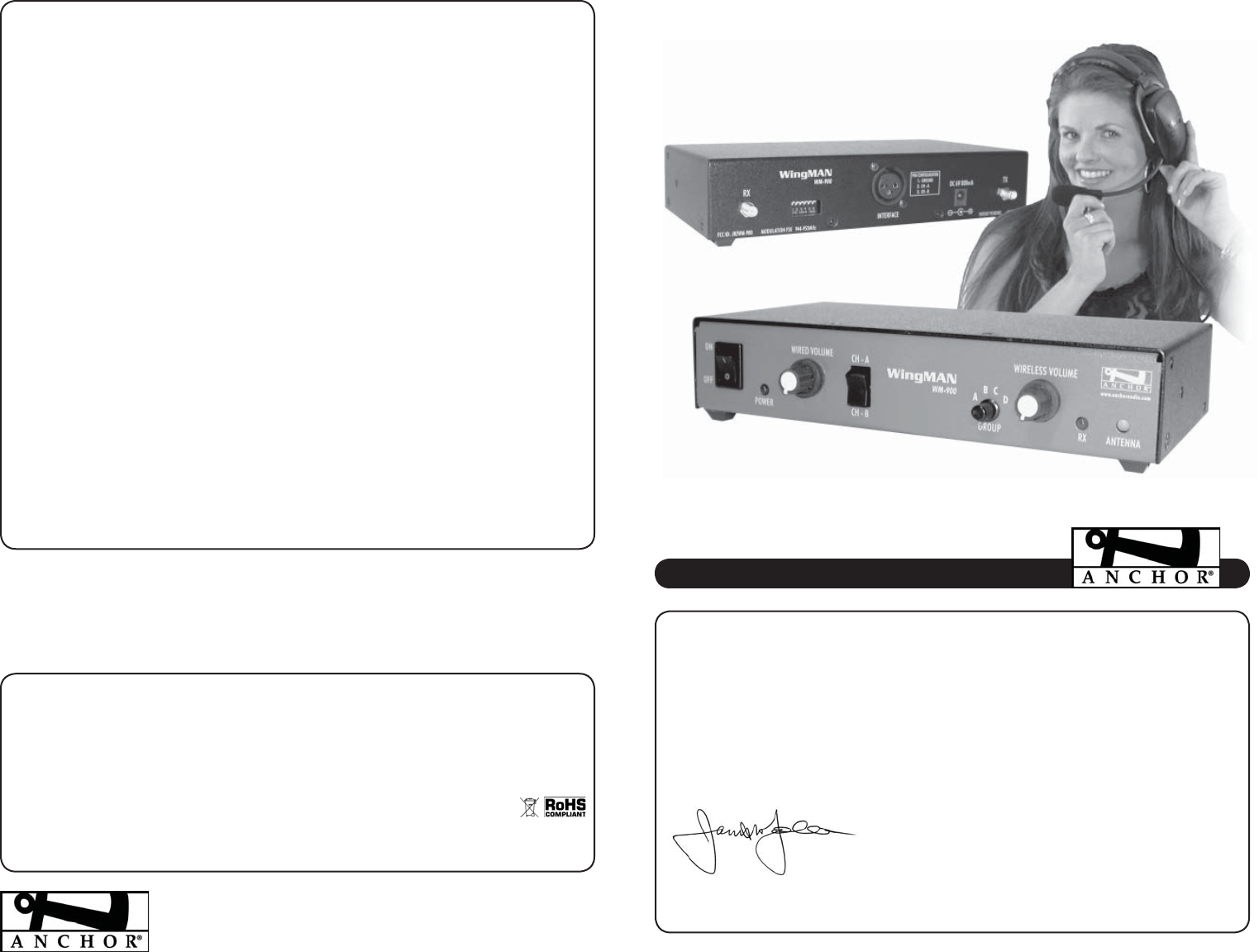
OWNER’S MANUAL
WINGMAN
INTERCOM ADAPTOR
WINGMAN TECHNICAL SPECIFICATIONS
Range (line of sight) 1,500’ / 450 m
FCC License User Registration
Selectable Wireless Groups 4
Selectable Wired Channels 2
Frequency 944 – 952 MHz
Frequency Settings 4 per Group
Output Power 8 dBm
DC Requirements 9V – 0.5A
Interface Connector 3-pin female XLR
Antenna 1/2 wave length dipole
Antenna Length 7.2” / 182 mm
Dimensions 8.5 x 4.5 x 1.7 in / 21.6 x 11.4 x 4.32 cm
Weight 2.4lbs / 1.1kg
FCC ID: J8ZWM-900
(Specifications subject to change without notice)
NEED MORE HELP? View demonstration videos on proper WingMAN setup & operation –
www.anchoraudio.com/wingman.php
GETTING STARTED
Please check your new unit carefully for any damage which
may have occurred during shipment. Each Anchor product
is carefully inspected at the factory and packed in specially
designed boxes for safe transport.
Notify the freight carrier immediately of any damage to the
shipping box or product. Repack the unit in the original box
and wait for inspection by the carrier’s claim agent. Notify
your dealer of the pending freight claim.
NOTE: All damage claims must be
made with freight carrier!
RETURNING SYSTEMS FOR SERVICE OR REPAIR
For service or repair, please contact the dealer you purchased
your system from or Anchor Audio Customer Service at (888)
444-6077 to obtain a RA
(Return Authorization)
number. All
shipments to Anchor Audio must include an RA number and
must be shipped prepaid. C.O.D. shipments will be refused
and returned at your expense.
IMPORTANT: Save the shipping box
& packing materials, they were
specially designed to ship your unit!
WARRANTY REGISTRATION
Visit our website at www.anchoraudio.com and select “War-
ranty Registration”. Complete the online form to activate the
two-year limited warranty on your WingMAN.
TROUBLESHOOTING?
INTERFERENCE IN ANCHORMAN HEADSETS?
Switch your belt pack settings to a different AnchorMAN
USER GROUP: A, B, C or D.
BACKGROUND NOISE TRANSMITTING ACROSS SYSTEM?
Reduce the headset microphone sensitivity level. Adjust the
AnchorMAN mic sensitivity with the +/– Microphone but-
tons on the belt pack.
TRANSMISSION IS WEAK?
Your rechargeable batteries may be running low. If batteries
are weak, the Group LED’s will slowly flash. Your belt pack
needs to be recharged. If you need to keep working, you can
use disposable alkaline batteries.
PROPER INTERCOM ETIQUETTE
WingMAN is an interface station that allows full duplex com-
munication between AnchorMAN belt packs and unbalanced
party-line intercom systems. Use proper intercom etiquette
– wait to break into the conversation network until the other
system users have stopped speaking.
ANCHOR AUDIO CUSTOMER SERVICE
888-444-6077
PIN CONFIGURATION
The WingMAN interface connector uses a 3-pin
XLR jack on the back panel. Connect the inter-
face box with the wired intercom system using
the 3 pin XLR jack on the rear panel.
Pin Configuration
Select Wired Channel (A or B) to be used
according to the pin description above (also
shown on pack panel). The Wired Channel
Switch matches the Anchor Audio PortaCOM
belt pack channels.
WHAT IS WINGMAN?
WingMAN is an interface station that allows full duplex communication be-
tween AnchorMAN belt packs and unbalanced party-line intercom systems.
The WingMAN includes a transceiver that operates in a FDMA format which is
compatible with AnchorMAN belt packs. An integrated interface circuit makes
it possible to easily interface the transceiver with party-line intercom systems.
This allows users to easily switch communications between one of the four An-
chorMAN groups and one of two party line groups.
ANTENNA PLACEMENT
In order to maximize system range/performance the WingMAN is designed
with dual antennas. Generally, the greater the antenna separation the better
WingMAN will perform. After connecting both antennas adjust their positions
until Strong signal quality is indicated by the ANTENNA LED.
The ANTENNA LED shows range/signal quality based on antenna separation:
RED = Weak Signal / Green = Strong Signal
For increased range and better signal quality mount antennas using the op-
tional Antenna Mounting Kit (includes cables & mounting hardware) to achieve
maximum separation. We recommend a minimum of 10’ between antennas .
BASIC SYSTEM OPERATION
1. Attach supplied antennas to the “RX” & “TX” back panel jacks.
2. Connect your wired intercom system to the 3-pin XLR back panel
jack “INTERFACE”.
3. Connect DC power supply.
4. Set DIP Switch #4 to designate wired intercom system.
DIP Switch #4 Settings:
ON (DOWN) – 100 ohm systems (Anchor Audio PortaCOM)
OFF (UP) – 200 ohm systems (Clearcom or RTS)
5. ANCHOR AUDIO PORTACOM USERS ONLY: Select wired channel
according to PIN CONFIGURATION on back panel.
6. Set GROUP knob to the AnchorMAN belt packs GROUP.
7. Turn the WingMAN power switch to ON.
8. Adjust WIRED & WIRELESS VOLUME to desired listening levels.
NOTE: AnchorMAN belt packs assigned to the
same Group & Frequency as the WingMAN will
experience interference when transmitting.
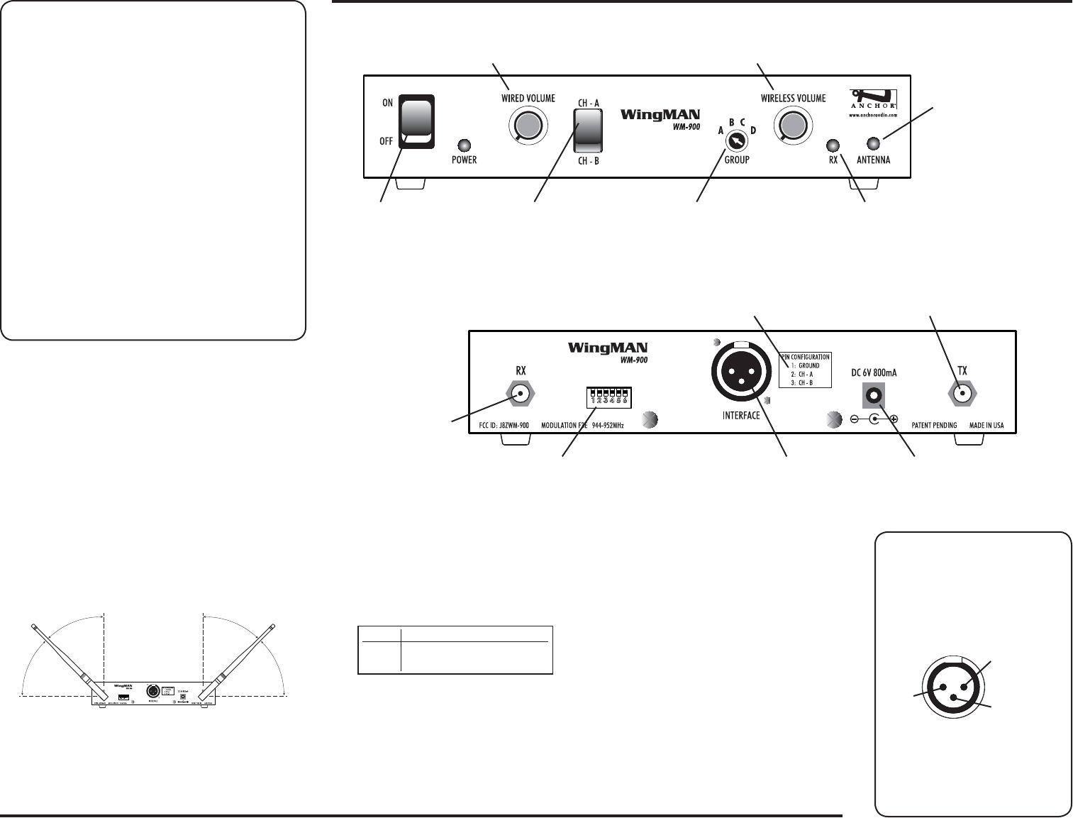
WINGMAN FRONT/BACK PANELS
Model Shown: WM-900
DIP SWITCHES
USER ID Selection – DIP Switches 1 & 2
WingMAN uses one of four GROUP/USER IDs to communicate
with the AnchorMAN. Select a USER ID (1 – 4) by setting DIP
Switches 1 & 2 on the back panel:
AnchorMAN belt packs with the same GROUP & USER ID setting
may experience significant transmission interference.
Wired Interface Setup – DIP Switch 4
Determines impedance match of the wired interface.
DIP Switch #4 Settings:
ON (DOWN) – 100 ohm systems
(Anchor Audio PortaCOM)
OFF (UP) – 200 ohm systems
(Clearcom or RTS)
WIRELESS TELEX (BTR-700) USERS
Follow these Setup Instructions to connect the WingMAN to a
BTR-700 Telex wireless base station:
1. Connect your BTR-700 (2-wire 3 pin XLR) output to the
3-pin XLR back panel jack “INTERFACE”.
2. Set WingMAN WIRED CHANNEL SWITCH to CH B.
3. Level adjustment on BTR-700 using the IN knob on
the BTR-700 front panel
4. Set WIRED & WIRELESS VOLUME on WingMAN to
maximum levels.
NEED MORE HELP? WingMAN setup &
operation videos:
www.anchoraudio.com/wingman.php
RECEIVE ANTENNA JACK
(see ANTENNA PLACEMENT)
DC POWER JACK
Connect DC power supply
TRANSMIT ANTENNA JACK
(see ANTENNA PLACEMENT)
WIRED SYSTEM INTERFACE
3-pin XLR jack – connect to
wired intercom system
DIP SWITCH
Setup USER ID & Select 100/200 ohm
operation
(see DIP SWITCHES)
XLR JACK PIN ASSIGNMENTS
(see PIN CONFIGURATION)
RECEIVE INDICATOR LED
Lights when signal is being received
ANCHORMAN GROUP SELECTOR
Set to match GROUP selection on
AnchorMAN belt packs
RECEIVE VOLUME CONTROL
Level of received signal going to the wired intercom system
TRANSMIT VOLUME CONTROL
Level of party line signal sent to the transmitter
POWER SWITCH WIRED CHANNEL SWITCH
Select channel for wired system
(see PIN CONFIGURATION)
ANTENNA SEPARATION
INDICATOR LED
System signal range/performance is
effected by antenna separation
RED Poor signal – increase
antenna separation
GREEN Optimum signal strength
SETTING LISTENING LEVELS
Adjust the WIRED VOLUME & WIRELESS VOLUME
knobs to match listening levels across systems
PIN 1:
Ground
PIN 2:
Wired Channel A
PIN 3:
Wired Channel B
SWITCH USER 1 USER 2 USER 3 USER 4
1 UP DOWN UP DOWN
2 UP UP DOWN DOWN