Andrew Wireless System CAPL7817E19 ION-E Remote Unit for cellular systems User Manual
Andrew Wireless System ION-E Remote Unit for cellular systems
Contents
- 1. user manual
- 2. installation instruction
- 3. Users Manual
user manual
ION®‐ESeriesLowPowerCarrierAccessPoint
InstallationGuide•M0201AAB•November2017
Preliminarydraftforuseincompliancetestingonly.Notfordistributiontocustomer.

DISCLAIMER
ThisdocumenthasbeendevelopedbyCommScope,andisintendedfortheuseofitscustomersandcustomersupport
personnel.Theinformationinthisdocumentissubjecttochangewithoutnotice.Whileeveryefforthasbeenmadeto
eliminateerrors,CommScopedisclaimsliabilityforanydifficultiesarisingfromtheinterpretationoftheinformation
containedherein.Theinformationcontainedhereindoesnotclaimtocoveralldetailsorvariationsinequipment,norto
provideforeverypossibleincidenttobemetinconnectionwithinstallation,operation,ormaintenance.Thisdocument
describestheperformanceoftheproductunderthedefinedoperationalconditionsanddoesnotcovertheperformance
underadverseordisturbedconditions.Shouldfurtherinformationbedesired,orshouldparticularproblemsarisewhichare
notcoveredsufficientlyforthepurchaser'spurposes,contactCommScope.
CommScopereservestherighttochangeallhardwareandsoftwarecharacteristicswithoutnotice.
COPYRIGHT
©2017CommScope,Inc.AllRightsReserved.
Thisdocumentisprotectedbycopyright.Nopartofthisdocumentmaybereproduced,storedinaretrievalsystem,or
transmitted,inanyformorbyanymeans,electronic,mechanicalphotocopying,recording,orotherwisewithouttheprior
writtenpermissionofCommScope.
Forpatentsseewww.cs‐pat.com.
TRADEMARKS
Alltrademarksidentifiedby®or™areregisteredtrademarksortrademarks,respectively,ofCommScope,Inc.Namesof
otherproductsmentionedhereinareusedforidentificationpurposesonlyandmaybetrademarksand/orregistered
trademarksoftheirrespectivecompanies.
AndrewWirelessSystemsGmbH,TBD‐November‐2017
ThisisNOTaCONSUMERdevice.ItisdesignedforinstallationbyFCCLICENSEESandQUALIFIED
INSTALLERS.YouMUSThaveanFCCLICENSEorexpressconsentofanFCCLicenseetooperatethisdevice.
Unauthorizedusemayresultinsignificantforfeiturepenalties,includingpenaltiesinexcessof$100,000
foreachcontinuingviolation.
ThisisNOTaCONSUMERdevice.ItisdesignedforinstallationbyFCCLICENSEESandQUALIFIED
INSTALLERS.YouMUSThaveanFCCLICENSEorexpressconsentofanFCCLicenseetooperatethisdevice.
YouMUSTregisterClassBsignalboosters(asdefinedin47CFR90.219)onlineat
www.fcc.gov/signal‐boosters/registration.Unauthorizedusemayresultinsignificantforfeiturepenalties,
includingpenaltiesinexcessof$100,000foreachcontinuingviolation.

T
ABLEOF
C
ONTENTS
DocumentOverview .................................................................................................................................................................................................. 1
DocumentRevisionHistory .................................................................................................................................................................................. 1
DocumentCautionsandNotes ............................................................................................................................................................................ 1
AbbreviationsUsedinthisGuide ......................................................................................................................................................................... 2
CommScopePartNumbers .................................................................................................................................................................................. 2
ION‐ESeriesSystemOverview .................................................................................................................................................................................. 3
CAPLOverview .......................................................................................................................................................................................................... 4
CAPLConnectors,Ports,andLEDs ...................................................................................................................................................................... 5
CAPLwithanOpticalFiberInterface ............................................................................................................................................................
6
CAPLwithaCopperInterfaceandExternalDCPower ................................................................................................................................. 7
CAPLwithaCopperInterfaceandPowerCat6ACable ................................................................................................................................ 8
PoweringaCAPLandPowerLEDBehavior .................................................................................................................................................. 9
FanInterfacePort ........................................................................................................................................................................................ 10
CAPLAccessoryOptions .................................................................................................................................................................................... 10
FanKit ........................................................................................................................................................................................................... 11
FlatMountingBracketKit ............................................................................................................................................................................ 11
CAPLMountingBracketKit ......................................................................................................................................................................... 11
CAPLHybridFiberSpliceBoxKit. ................................................................................................................................................................ 12
AC/DCPowerSupplyKit ............................................................................................................................................................................... 12
OCTISKits ..................................................................................................................................................................................................... 12
InstallingCAPLs ....................................................................................................................................................................................................... 13
SafelyWorkingwithION‐EHardware ................................................................................................................................................................ 13
EquipmentSymbolsandCompliance .......................................................................................................................................................... 13
HealthandSafetyPrecautions..................................................................................................................................................................... 13
PropertyDamageWarnings ......................................................................................................................................................................... 14
GeneralInstallationSafetyRequirements................................................................................................................................................... 14
GuardAgainstDamagefromElectro‐StaticDischarge ............................................................................................................................... 14
PrepareforInstallation ...................................................................................................................................................................................... 15
CAPLInstallationRules ...................................................................................................................................................................................... 15
CascadeRules ..................................................................................................................................................................................................... 16
RecommendedToolsandMaterial ............................................................................................................................................................. 16
DeterminethePowerConsumptionoftheCAPL ....................................................................................................................................... 17
DeterminetheCAPLMountingSite ............................................................................................................................................................ 17
GeneralMountingCautions ......................................................................................................................................................................... 20
UnpackandInspecttheCAPLandOptionalAccessories ........................................................................................................................... 20
MounttheCAPL ................................................................................................................................................................................................. 20
Flat‐SurfaceMountaCAPL ......................................................................................................................................................................... 21
WallMountaCAPL ...................................................................................................................................................................................... 22
MountingOrientationforWallMounts ................................................................................................................................................ 22
WallMountaCAPLUsingaFlatMountingBracketKit ....................................................................................................................... 24
WallMountaCAPLUsingaCAPLHybridFiberSpliceBoxKit ............................................................................................................ 26
WallMountaCAPLUsingaAC/DCPowerSupplyKit .......................................................................................................................... 31
CeilingMountaCAPL .................................................................................................................................................................................. 34
CeilingMountaCAPLwithoutaFanKit ............................................................................................................................................... 34
CeilingMountaCAPLwithaFanKit .................................................................................................................................................... 34
(Optional)GroundtheCAPL .............................................................................................................................................................................. 35
ConnecttheCAPLCables ................................................................................................................................................................................... 36
CableaCAPLwithanOpticalFiberInterface ............................................................................................................................................. 36
CableaCAPLwithaCopperInterface ........................................................................................................................................................ 39
Cat6ACableRequirementsforCAPLswithaCopperInterface .......................................................................................................... 39
CableaCAPLwithaCopperInterfaceandExternalDCPower ........................................................................................................... 42
CableaCAPLwithaCopperInterfaceandPoweroverCat6ACable .................................................................................................. 44
CAPLMaintenance ................................................................................................................................................................................................. 47
RemoveaCAPLfromaWallorCeilingMount .................................................................................................................................................. 47
PreventativeCAPLMaintenanceforCAPLswiththeFanKitOption .............................................................................................................. 47
CAPLSpecifications ................................................................................................................................................................................................. 48
CAPLOutputSpecifications ............................................................................................................................................................................... 48
CAPLBandwidthSpecifications ......................................................................................................................................................................... 49
Cat6ASpecificationsandTestingRequirements ............................................................................................................................................... 49
ComplianceandStandardsCertification ................................................................................................................................................................ 51
FCCRFExposureRequirements ......................................................................................................................................................................... 51
EMCStandards.................................................................................................................................................................................................... 51
FCCandISEDStandards ...................................................................................................................................................................................... 52
M0201AABION®‐ESeriesLowPowerCarrierAccessPointInstallationGuide
©November2017CommScope,Inc.Page1

TableofContents
ContactingCommScope .......................................................................................................................................................................................... 53
DCCSGlobalTechnicalSupport .......................................................................................................................................................................... 53
TelephoneHelplines .................................................................................................................................................................................... 53
OnlineSupport ............................................................................................................................................................................................. 53
WasteElectricalandElectronicEquipmentRecycling ....................................................................................................................................... 53
HardwaretoSoftwareMappingInformation .................................................................................................................................................... 54
DCCSTechnicalTraining ..................................................................................................................................................................................... 54
AccessingION‐ESeriesUserDocumentation .................................................................................................................................................... 55
ION®‐ESeriesLowPowerCarrierAccessPointInstallationGuideM0201AAB
Page2©November2017CommScope,Inc.
M0201AAB
©November2017CommScope,Inc.
ION®‐ESeriesLowPowerCarrierAccessPointInstallationGuide
Page1
D
OCUMENT
O
VERVIEW
ThisinstallationguideprovidesaproductoverviewandinstallationinstructionsfortheION‐ESeriesLow
PowerCarrierAccessPoint(CAPL),whichallowstransmissionbetweenION‐Eequipment,antennas,and
Ethernetdevices(suchasWiFiandIPcameras).
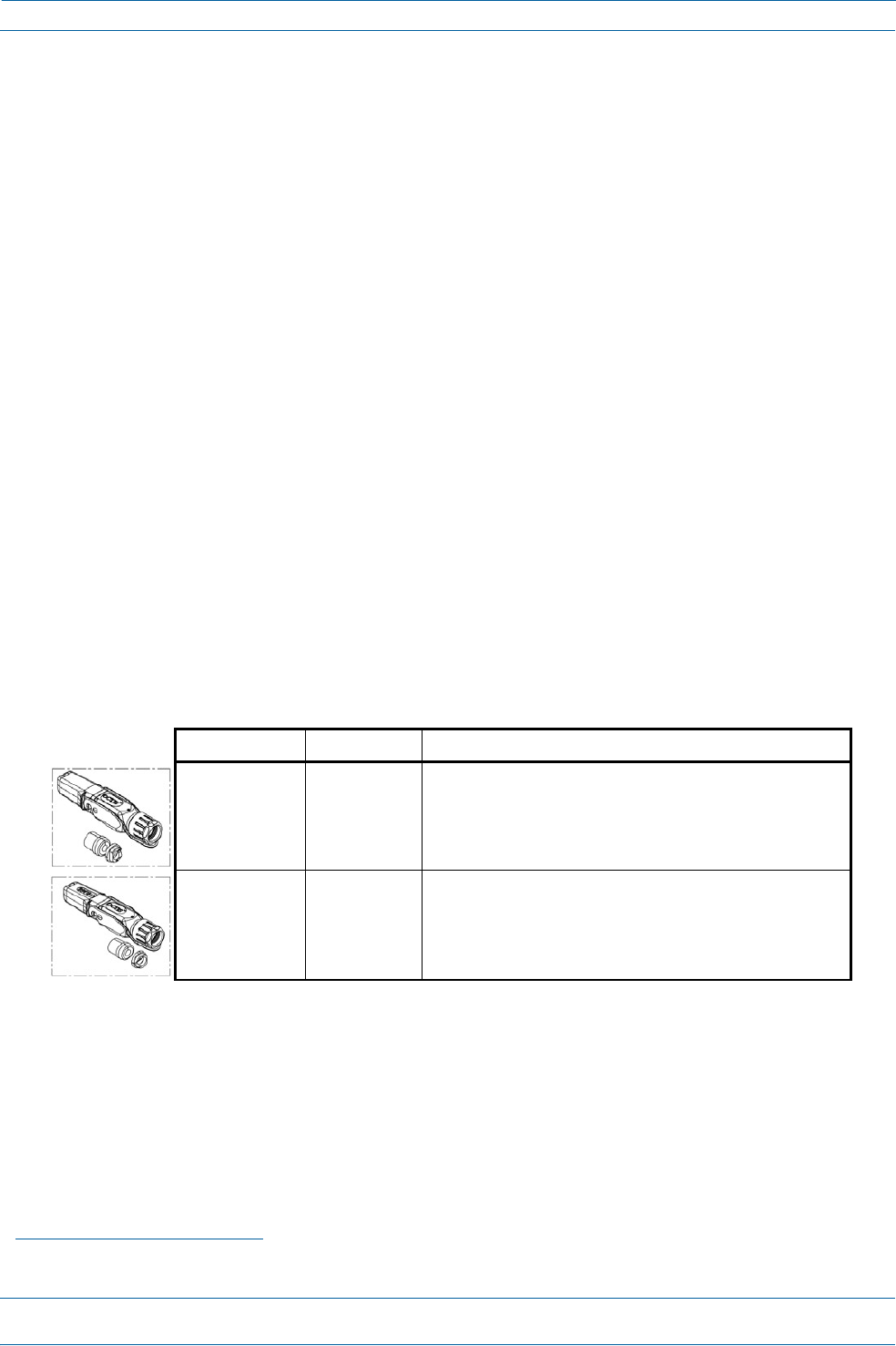
Table1liststheCAPLmodelsthatthisinstallationguidesupports.
Table1.SupportedCAPLModels
ForfurtherinformationonotherION‐Esystemcomponents,refertoanyofthedocumentslistedbelow;
see"AccessingION‐ESeriesUserDocumentation”onpage55).
•
ION‐ESeriesWCS‐2,WCS‐4,ande‐POISubracksandPowerSupplyUnitInstallationGuide
•
ION‐ESeriesUniversalAccessPointInstallationGuide.
DocumentRevisionHistory
IssueDocumentPNDocumentDateTechnicalUpdates
1M0201AAAOctober2017InitialRelease.
2M0201AABNovember2017Addssupportfor7/80‐85/17E/19.
DocumentCautionsandNotes
Thisdocumentcontainsnotes,cautions,andwarnings.Ingeneral,cautions,warnings,andnotesindicatethe
following:
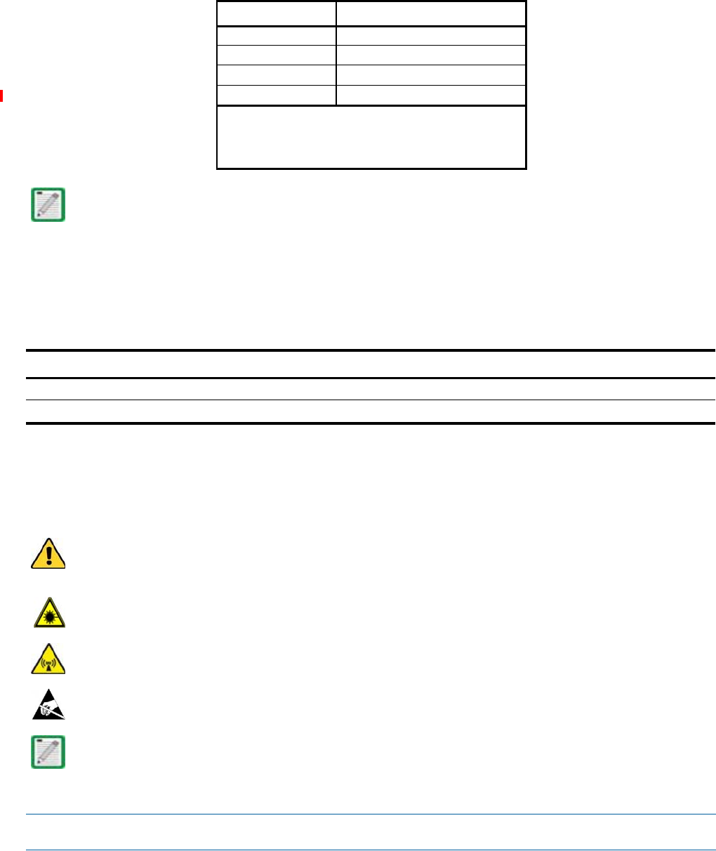
Theicontotheleftisusedtoindicateacautionorwarning.Cautionsandwarningsindicateoperationsor
stepsthatcouldcausepersonalinjury,induceasafetyprobleminamanageddevice,destroyorcorrupt
information,orinterruptorstopservices.
Theicontotheleftindicatesacautionorwarningthatpertainstolaserequipment.
TheicontotheleftisindicatesacautionorwarningthatpertainstoRadioFrequency(RF).
TheicontotheleftindicatesthatthehardwareissusceptibletoElectro‐StaticDischarge(ESD)damage.
TheicontotheleftisindicatesaNote.Notesprovideinformationaboutspecialcircumstances.
PartNumber
1
ModelName
7770203‐000x CAPL17E/17E/23/23
7770209‐000x CAPL18/21/26/26
7770356‐000x CAPL17E/17E/19/19
7776596‐000xCAPL7/80‐85/17E/19
1The“‐000x”suffixprovidesinformationastowhetherthe
CAPLhasaFiberorCopperinterface,andthepowerand
FanKitoptions.Contactyourlocalsalesrepresentativefor
furtherinformation.

ION®‐ESeriesLowPowerCarrierAccessPointInstallationGuide
Page2
M0201AAB
©November2017CommScope,Inc.
DocumentOverview
AbbreviationsUsedinthisGuide
AUXAuxiliaryISED Innovation,ScienceandEconomicDevelopmentCanada
C
CelsiuskgKilogram
CANCentralAreaNodeLEDLightEmittingDiode
CAPLCarrierAccessPoint,LowPowerMHzMegahertz
CatCategorymmMillimeter
CATCopperTransportMMFMulti‐ModeFiber
dBDecibelOPTOpticalTransport
dBmDecibel‐milliwattsPNPartNumber
DCDirectCurrentRANRegional‐AreaNetwork
DCCSDistributedCoverageandCapacitySolutionsRFRadioFrequency
EFTAEuropeanFreeTradeAssociationRURackUnit
EMCElectromagneticCompatibilitySFPSmallForm‐FactorPluggable
EUEuropeanUnionSMFSingle‐ModeFiber
F
FahrenheitTENTransportExpansionNode
FCCFederalCommunicationsCommissionUAPUniversalAccessPoint
GbGigabyteVdcVolts,directcurrent
GHzGigahertzWWatts
CommScopePartNumbers
TheCommScopeION‐Epartnumbersinthisinstallationguideareintheformatofnnnnnnn‐xx,wherethe
“‐xx”suffixindicatesthelatestrelease.ContactyourlocalCommScopesalesrepresentativeforthecurrent
releasepartnumber.
M0201AAB
©November2017CommScope,Inc.
ION®‐ESeriesLowPowerCarrierAccessPointInstallationGuide
Page3
ION‐ES
ERIES
S
YSTEM
O
VERVIEW
ION‐ESeriesSystemOverview
ThissectiondescribestheION‐Esystem,whichisaunifiedwirelessinfrastructureplatformdefinedaround
ITbasedarchitecture.Itbringstogetherlicensedwirelessandpower,plusGigabitEthernetforWiFiintoone
wirelesssystemthatcanscaletobuildingsizeandistechnologyandspectrumagnosticandadaptive.Abasic
ION‐Esystemcomprisesthecomponentslistedbelow;seealsoFigure1.
•
CentralAreaNode(CAN)—providesserver‐levelcontrolandprimarysignaldistribution.WCS‐2(2U)
andWCS‐4(4U)Subrackoptionsareavailable.
•
TransportExpansionNode(TEN)—connectstoaCANusingMulti‐ModeorSingle‐Modefiberasa
secondarydistributionpoint.WCS‐2(2U)andWCS‐4(4U)Subrackoptionsareavailable.
AWCS‐2andaWCS‐4canbeconfiguredforuseasaCANoraTEN.Whentheinformationinthisguide
appliestobothconfigurations,theterm“CAN/TEN”isused.Whentheinformationpertainstoonlyone
oftheconfigurations,thatconfigurationwillbeidentifiedsingularlyas“CAN”or“TEN.”
•
AccessPoint—connectsaCANoraTENtoantennasorotherwirelessdevices.Onthedownlink,an
AccessPoint(AP)convertsdataarrivingattheAPtoanalogsignalsandsendsthemtoanantenna.Onthe
uplink,receivedsignalsaredigitizedandserializedintodatastreamswhicharesentbacktothe
CAN/TEN.EachAPcontainsuptofourtransceiverpathsforRFcoverage.APssupportsGigabitEthernet
forWiFi,IPcameras,orotherdevicesinadditiontowirelessoveracommoncable.AnAPcanbeanyof
thefollowing:
–
UniversalAccessPoint(UAP)—connectstheCAN/TENtoaninternalantenna;receivesdataand
powerthroughCat6Atwistedpaircabling.
–
UAP‐X—similarinfunctionasthestandardUAP,inadditiontoCommercialfrequencies,theUAP‐X
alsosupportsPublicSafetyfrequencies,including700,800and400MHz.TheUAP‐Xconnectsthe
CAN/TENtoexternalantennasandsupportsanextensivefrequencyrange.
–
UAP‐N25andUAP‐XN25—similarinfunctionastheUAPandUAP‐X,theUAP‐N25andUAP‐XN25
featurea25MHzfilterononepath(insteadofthe80MHzfilteronaUAPorUAP‐X).Thisallows
coexistenceofspecificbands,suchasAustralia850MHzand900MHz.
–
LowPowerCarrierAccessPoint(CAPL)—interfaceswiththeCAN/TENviaaCat6Acableoran
opticallink.ThisallowstheCAPLtoprovidedataoverCopper,Single‐ModeFiber(SMF),or
Multi‐ModeFiber(MMF).PowerforCAPLswithaCopperInterfacecanbeprovidedoverCat6Aor
ExternalAC/DC.PowerforCAPLswithaFiberInterfaceisprovidedoverExternalAC/DCorremotely
throughhybridfiber.
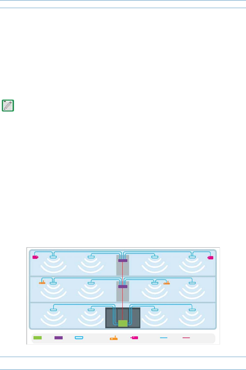
Figure1.BasicION‐ESystem
CANTENAccessPointWiFiIPCameraCat6AMM/SMFiber
ION®‐ESeriesLowPowerCarrierAccessPointInstallationGuide
Page4
M0201AAB
©November2017CommScope,Inc.
CAPLOverview
CAPLOVERVIEW
TheLowPowerCarrierAccessPoint(CAPL)interfaceswiththeCAN/TENviaaCat6Acableoranopticallink.
ThisallowstheCAPLtoprovidedataoverCopper,Single‐ModeFiber(SMF),orMulti‐ModeFiber(MMF).
PowerforCAPLswithaCopperInterfacecanbeprovidedoverCat6AorexternalDC.PowerforCAPLswith
aFiberInterfaceisprovidedoverExternalAC/DCorremotelythroughhybridfiber.
Onthedownlink,theCAPLconvertsdataarrivingattheCAPLtoanalogsignalsandsendsthemtothe
Antennaports.Ontheuplink,receivedsignalsaredigitizedandserializedintodatastreams,whicharesent
backtotheCAN/TEN.EachCAPLcanprovideRFcoverageforuptofourspecificfrequencybands.Figure2
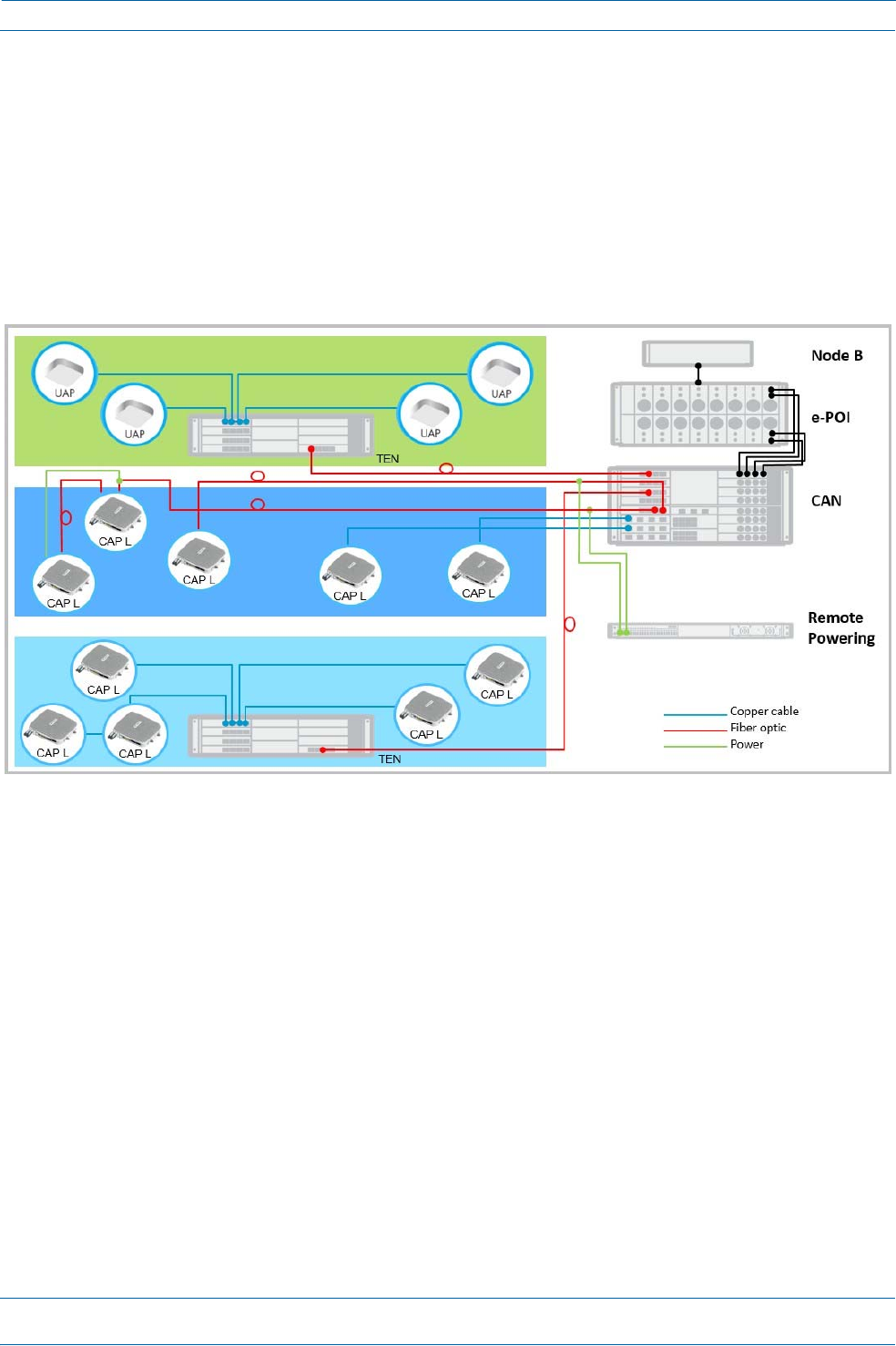
showshowaCAPLcanbedeployedinanION‐Esystem.
TheCAPL
Figure2.CAPLinanION‐ESystem
•
operateswithinthefollowingtemperatureranges
–
CAPLwithoutaFanKit(passivelycooled)
Opticalunits:‐33°Cto+40°C(‐27.4°Fto104°F)
Cat6Aunits:0°Cto+40°C(32°Fto104°F)
–
CAPLwithaFanKit,themaximumoperatingtemperatureincreasesto55°C(131°F);seealso"Fan
Kit”onpage11
•
isoutdoorrated(IP67),however,theCat6Aunitsarenotdesignedforoutdooruse;see"MounttheCAPL”
onpage20.
•
hasatypicalpowerconsumptionof98W;seealso
–
"FanKit”onpage11
–
"DeterminethePowerConsumptionoftheCAPL”onpage17.

M0201AAB
©November2017CommScope,Inc.
ION®‐ESeriesLowPowerCarrier
A
ccessPointInstallationGuide
Page5
CAPLOverview
CAPLConnectors,Ports,andLEDs
Thefollowingsectionsidentifytheconnectors,ports,andLEDsavailableonthedifferentCAPLmodels:
•
"CAPLwithanOpticalFiberInterface”onpage6
•
"CAPLwithaCopperInterfaceandExternalDCPower”onpage7
•
"CAPLwithaCopperInterfaceandPowerCat6ACable”onpage8
•
"PoweringaCAPLandPowerLEDBehavior”onpage9
•
"FanInterfacePort”onpage10.
ION®‐ESeriesLowPowerCarrierAccessPointInstallationGuide
Page6
M0201AAB
©November2017CommScope,Inc.
CAPLOverview
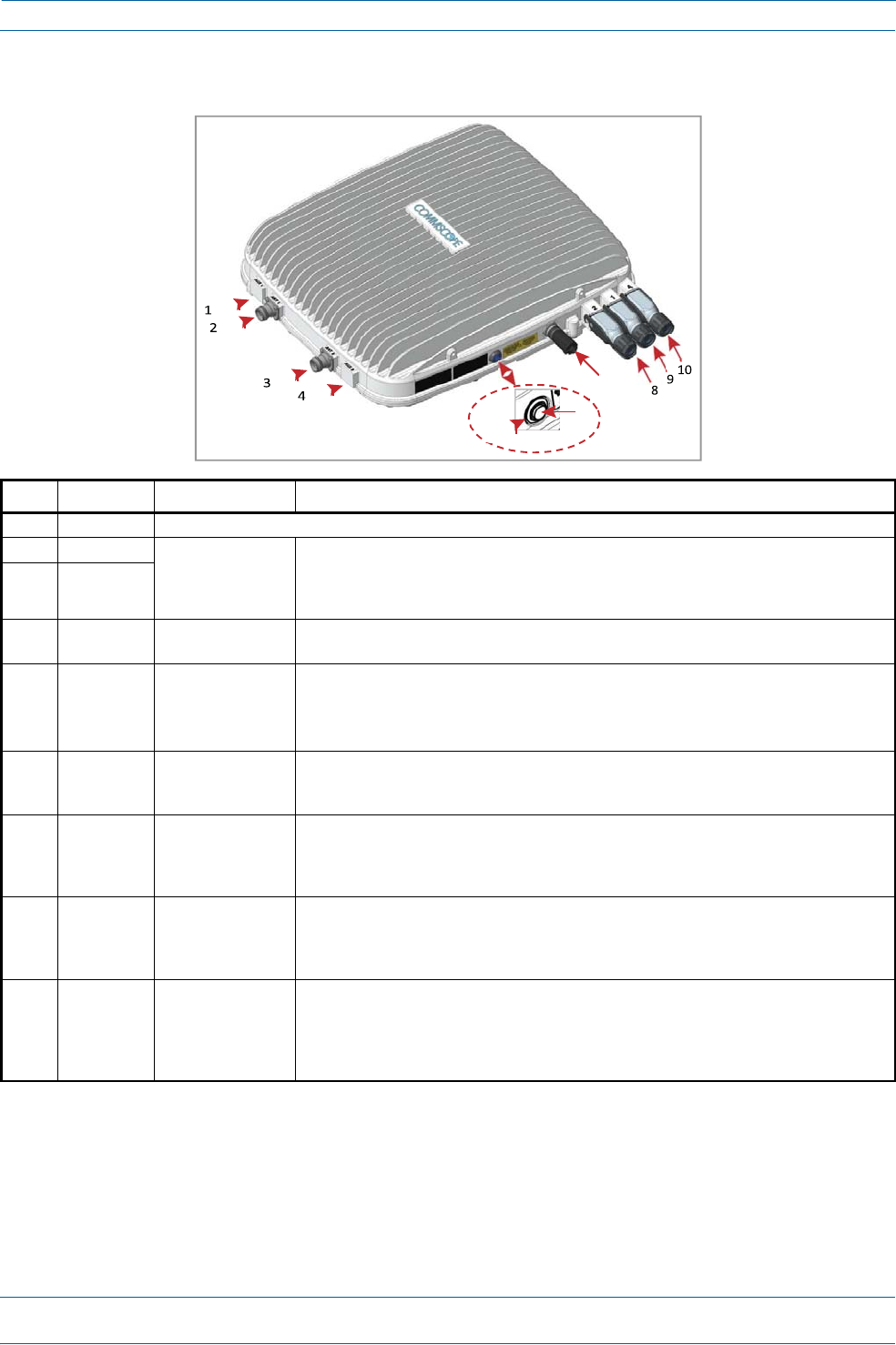
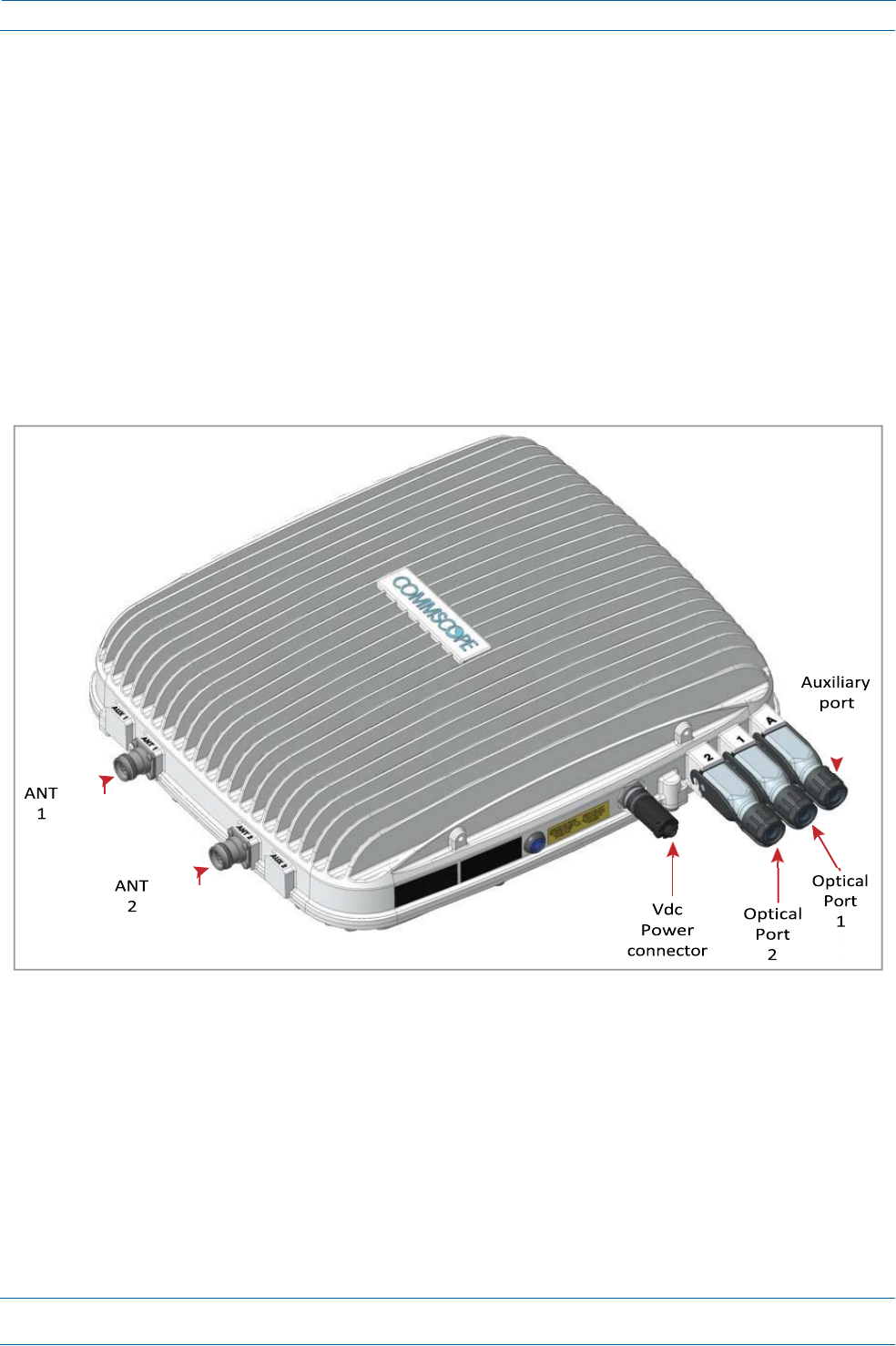
CAPLwithanOpticalFiberInterface
REF#LabelDescriptionFunction
1,4ANT3,ANT4Notavailable;connectorisplugged.
2ANT1
4.3‐10RFconnector
Connecttotwoseparateexternalantennasortotwoportsonacross‐polarizeddualantenna
via50 coaxialcable.EachconnectorsupportstwoRFbands.Theendofthe50 coaxialcable
thatconnectstoanANTconnectorcanbeeitherapush‐pullorathreadedconnector.ANT1/2
shipwithdustcapsthatcanbediscardeduponunitinstallation.
3ANT2
5PowerLED
(Unlabeled)
PowerLEDSee"PoweringaCAPLandPowerLEDBehavior”onpage9.
6Powerbutton
(Unlabeled)
PushbuttonswitchPlacestheCAPLintoalow‐powersleepstate,whichallowsyoutosafelyunplugtheCAPL
withoutapowerarc.
CAUTION!PriortodisconnectingthePowercablefromtheCAPL,pressthePowerbutton
topowerofftheCAPL.
7UnlabeledProprietary4‐pin36
to60VdcPower
connector
ConnectstoalocalorremoteDCpowersupply,ortoaHybridFiberJunctionBox.
82OpticalPort2ConnectstoanoptionalcascadedCAPLviaanOpticalOCTISKit(PN7770612).Port2provides
themainsignalinterface.OpticaltransportoccursoverSingleModeFiber(SMF)orMultiMode
Fiber(MMF).Port2shipswithfactory‐installedEMI/weatherproofplug,andmustremain
pluggedifnotinuse.
91OpticalPort1ConnectstoanION‐ECAN/TEN(possiblythroughalocalHybridFiberJunctionBox)and
providesthemainsignalinterface.OpticaltransportoccursoverSingleModeFiber(SMF)or
MultiModeFiber(MMF).UsestheOpticalOCTISKit(PN7770612).Port1shipswithadustcap
thatcanbediscardeduponunitinstallation.
10ARJ45AuxiliaryportConnectstoexternalEthernetdevicessuchasWiFiandIPcameras.Cablingisviathe
appropriateCATcablefortheprotocol;thismodelsupportsa1000BASE‐Tand802.3atClass4
PoweroverCat6AEthernetconnection.Maximumattachedcablelengthis3meters(9.8feet).
ForinformationontheAuxiliaryportincascades,see"CascadeRules”onpage16.PortAships
withfactory‐installedEMI/weatherproofplug,andmustremainpluggedifnotinuse.
7
6
5
M0201AAB
©November2017CommScope,Inc.
ION®‐ESeriesLowPowerCarrierAccessPointInstallationGuide
Page7
CAPLOverview
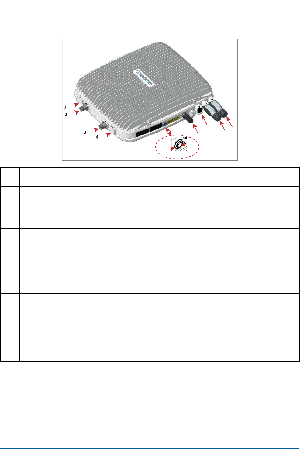
CAPLwithaCopperInterfaceandExternalDCPower
REF#LabelDescriptionFunction
1,4ANT3,ANT4Notavailable;connectorisplugged.
2ANT1
4.3‐10RFconnector
Connecttotwoseparateexternalantennasortotwoportsonacross‐polarizeddualantenna
via50 coaxialcable.EachconnectorsupportstwoRFbands.Theendofthe50 coaxial
cablethatconnectstoanANTconnectorcanbeeitherapush‐pullorathreadedconnector.
ANT1/2shipwithdustcapsthatcanbediscardeduponunitinstallation.
3ANT2
5PowerLED
(Unlabeled)
PowerLEDSee"PoweringaCAPLandPowerLEDBehavior”onpage9.
6Powerbutton
(Unlabeled)
PushbuttonswitchPlacestheCAPLintoalow‐powersleepstate,whichallowsyoutosafelyunplugtheCAPL
withoutapowerarc.
CAUTION!PriortodisconnectingthePowercablefromtheCAPL,pressthePower
buttontopowerofftheCAPL.
7UnlabeledProprietary4‐pin36
to60VdcPower
connector
ConnectstoalocalorremoteDCpowersupply,ortoaHybridFiberJunctionBox.
82Port2Notapplicabletothismodelconfiguration—donotremovethefactory‐installed
EMI/weatherproofplug.
91Port1Port1connectstoanavailableportonaCATCardintheCAN/TENviaCat6Acableand
providesthemainsignalinterface.UsestheEthernetOCTISKit(PN7760652).Port1shipswith
adustcapthatcanbediscardeduponunitinstallation.
10ARJ45AuxiliaryportTheAuxiliaryportprovidesacascadeconnectiontoanoptionallocallypoweredcascaded
CAPL,orprovidesaconnectiontoexternalEthernetdevicessuchasWiFiandIPcameras.
CablingisviatheappropriateCATcablefortheprotocol;thismodelsupportsa1000BASE‐T
and802.3atClass4PoweroverCat6AEthernetconnection.Maximumattachedcablelength
is100meters(328feet).PortAshipswithfactory‐installedEMI/weatherproofplug,andmust
remainpluggedifnotinuse.ForinformationonhowtousetheAuxiliaryportincascades,see
"CascadeRules”onpage16.
8
7910
6
5
ION®‐ESeriesLowPowerCarrierAccessPointInstallationGuide
Page8
M0201AAB
©November2017CommScope,Inc.
CAPLOverview
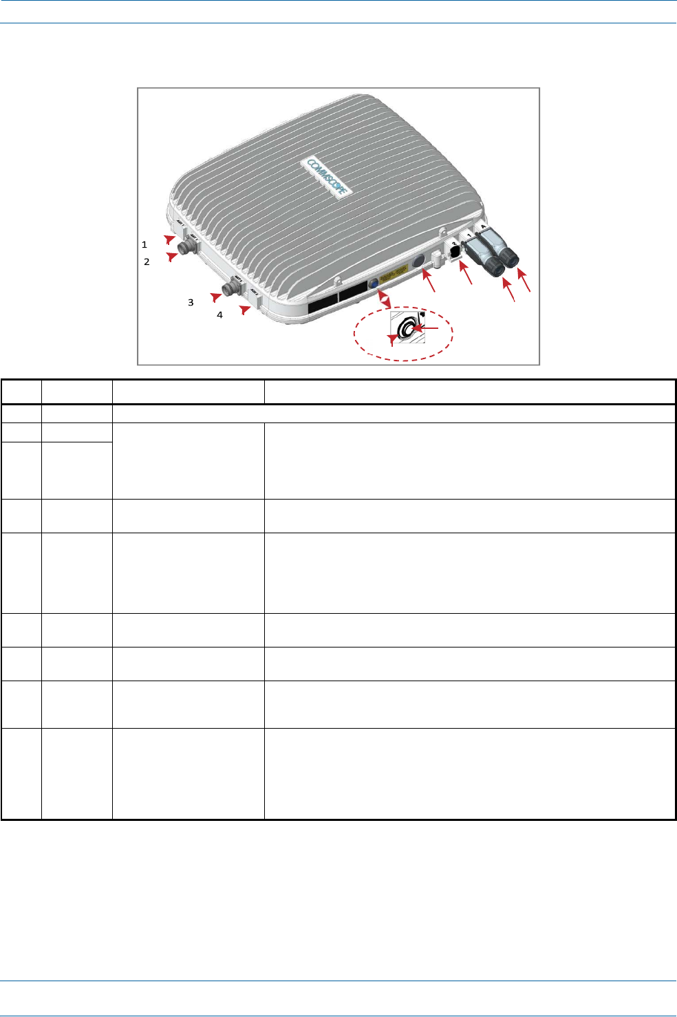
CAPLwithaCopperInterfaceandPowerCat6ACable
REF#LabelDescriptionFunction
1,4ANT3,ANT4Notavailable;connectorisplugged.
2ANT1
4.3‐10RFconnector
Connecttotwoseparateexternalantennasortotwoportsonacross‐polarizeddual
antennavia50 coaxialcable.EachconnectorsupportstwoRFbands.Theendofthe
50 coaxialcablethatconnectstoanANTconnectorcanbeeitherapush‐pullora
threadedconnector.ANT1/2shipwithdustcapsthatcanbediscardeduponunit
installation.
3ANT2
5PowerLED
(Unlabeled)
PowerLEDSee"PoweringaCAPLandPowerLEDBehavior”onpage9.
6Power
button
(Unlabeled)
PushbuttonswitchPlacestheCAPLintoalow‐powersleepstate,whichallowsyoutosafelyunplugthe
CAPLwithoutapowerarc.PowertoaCat6ACAPLmayalsobeshutdownviathe
ION‐ESeriesSoftware.
CAUTION!PriortodisconnectingthePowercablefromtheCAPL,pressthe
PowerbuttontopowerofftheCAPL.
7UnlabeledProprietary4‐pin36to60Vdc
PowerconnectorPlugged,notapplicabletothismodelconfiguration.
82Port2Notapplicabletothismodelconfiguration—donotremovethefactory‐installed
EMI/weatherproofplug.
91Port1Port1connectstoanavailableportonaCATCardintheCAN/TENviaCat6Acableand
providesthemainsignalinterfaceandpoweroverCat6A.UsestheEthernetOCTISKit
(PN7760652).Port1shipswithadustcapthatcanbediscardeduponunitinstallation.
10ARJ45AuxiliaryportTheAuxiliaryportprovidesacascadeconnectiontoanoptionallocallypowered
SecondaryCAPL,orprovidesaconnectiontoexternalEthernetdevicessuchasWiFi
andIPcameras.CablingisviatheappropriateCATcablefortheprotocol;thismodel
supportsa1000BASE‐Tand802.3atClass4PoweroverCat6AEthernetconnection.
Maximumattachedcablelengthis100meters(328feet).PortAshipswith
factory‐installedEMI/weatherproofplug,andmustremainpluggedifnotinuse.
78
910
6
5

M0201AAB
©November2017CommScope,Inc.
ION®‐ESeriesLowPowerCarrierAccessPointInstallationGuide
Page9
CAPLOverview
PoweringaCAPLandPowerLEDBehavior
TheCAPLispoweredonassoonaspowerisconnectedtoit.Undernormaloperatingconditions,thePower
LEDturnsonbrieflywhentheunitisfirstdetected.Itwillthengooutbriefly,followedbyaninitialization
periodduringwhichthePowerLEDflashesslowlywhiletheCAPLisconfigured.ThePowerLEDremainsa
steadyblue(notflashing)oncetheunitreachesafullyoperationalstate,whichtypicallyoccurswithin45
seconds.
IfyoupresstheCAPLPower‐Downbutton,theCAPLwillgointosleepmode.Thisallowsyoutosafely
disconnectanycablesconnectedtotheCAPL.
IfyoupressthePower‐Downbutton,theonlywaytobringtheCAPLbacktoafullyoperationalstate,istodo
oneofthefollowing:
•
DisconnectthedatacablefromPort1,andthenreconnectit.
•
Foranexternally‐poweredCAPL,removethepowercablefor10seconds,andthenreconnectit.
•
PowerLEDbehaviorforaCAPLwithaFiberInterface
–
Off—CAPLisnotpoweredon.
–
Steadyblue—CAPLispoweredonandoperational.
–
Slowflashingblue—CAPLispoweredonandinitializing.
–
Rapidflashingblue—CAPLUnitIdentifieractiveviatheFlashLEDfunctionintheION‐EGUI.
•
PowerLEDbehaviorforaCAPLwithaCopperInterface
–
Off—CAPLisnotpoweredon.
–
Steadyblue—CAPLispoweredonandoperational.
–
Slowflashingblue—CAPLispoweredonandinitializing.
–
Rapidflashingblue—CAPLUnitIdentifieractiveviatheFlashLEDfunctionintheION‐EGUI.
–
Slowpulseblue(ION‐ESoftwareV2.3orlateronly)—ifthePowerLEDcyclesthroughaslowincrease
inbrightnessfor1secondfollowedbyaslowdecreaseinbrightnessfor1second,theCAPLis
poweredonbutiscurrentlyunabletoestablisha10GbpsdatalinktotheWCSSubrack.Therearetwo
possiblecauses:
Thereisaninstallationproblem,suchasadefectivecableorconnector,acablethatistoolong,or
acablecrosstalkproblem.AnyoftheseproblemscanleadtoinadequateSNRattheremoteunit
andaninabilitytolink.(Thisisthemostlikelycauseifthisisanewly‐installedunit.)
Thisconditioncanalsobetriggeredwhenacrystaloscillatorhasagedoverthecourseofseveral
years.Inthiscase,thefailuretolinkatstartupwillinitiateaself‐calibrationprocesswhichcan
takeseveralminutes.Oncethisself‐calibrationiscomplete,theunitwillresumenormal
operation.(Thisisthemostlikelycauseforunitswhichhaveworkedcorrectlyinthepast.)
ION®‐ESeriesLowPowerCarrierAccessPointInstallationGuide
Page10
M0201AAB
©November2017CommScope,Inc.
CAPLOverview
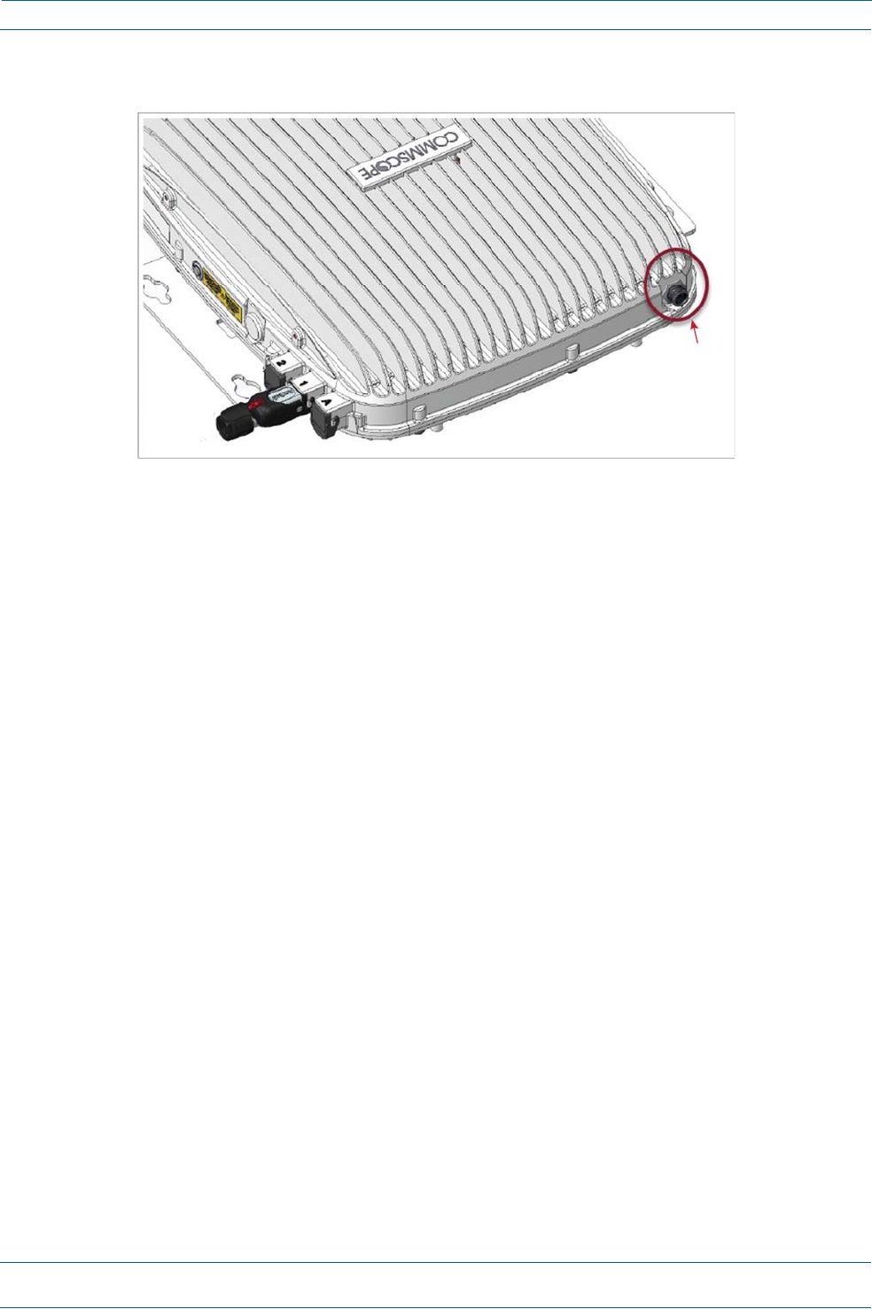
FanInterfacePort
Theprecedinggraphicshowstheproprietary8‐pinFanInterfaceport,whichisonlyavailableonCAPLunits
thatshipwiththefactory‐installedFanKit.IftheCAPLbeinginstalledincludestheFanKitoption,theFan
InterfaceportwillbecabledtotheFanKitatthefactory.IftheCAPLbeinginstalleddoesnotincludetheFan
Kitoption,theFanInterfaceportwillbeplugged.
CAPLAccessoryOptions
ThefollowingsectionsdescribehardwareoptionsfortheCAPL:
•
"FanKit”onpage11
•
"FlatMountingBracketKit”onpage11
•
"CAPLMountingBracketKit”onpage11
•
"CAPLHybridFiberSpliceBoxKit”onpage12
•
"AC/DCPowerSupplyKit”onpage12
•
"OCTISKits”onpage12.
Fan
Interfac
eport
M0201AAB
©November2017CommScope,Inc.
ION®‐ESeriesLowPowerCarrierAccessPointInstallationGuide
Page11
CAPLOverview
FanKit
TheoptionalFanKitisanintegratedshroudthatfitsovertheCAPLenclosuretoextendtheupperambient
temperaturerange.TheFanKit
•
isIP55rated
•
increasesthemaximumoperatingtemperatureto55°C(131°F)
•
adds3WpowerconsumptiontotheCAPL;see"DeterminethePowerConsumptionoftheCAPL”on
page17.
•
isfactoryinstalled,butcanbereplacedinthefield.
FlatMountingBracketKit
TheFlatMountingBracketKit(CommScopePN7774353‐xx)providesthemountingbracketsrequiredto
mountanCAPLtoawallorotherflatsurface.See"WallMountaCAPLUsingaFlatMountingBracketKit”on
page24.
CAPLMountingBracketKit
TheCAPLMountingBracketKit(CommScopePN7774354‐xx)providesthemountingbracketsrequiredto
mountanCAPLtoawallorotherflatsurfacewhenusingthe“CAPLHybridFiberSpliceBoxKit”orthe
“AC/DCPowerSupplyKit.”
FanKit
ION®‐ESeriesLowPowerCarrierAccessPointInstallationGuide
Page12
M0201AAB
©October2017CommScope,Inc.
CAPLOverview
CAPLHybridFiberSpliceBoxKit
TheCAPLHybridFiberSpliceBoxKit(CommScopePN7781091‐xx)separatesthepowerfromthefiber
signalsonahybridfiberfeedfromtheCAN/TEN.ItfeedspowertotheCAPLthroughacompositecablethat
includesbothfiberandcopperpowerwires.FiberandcopperterminateattheSpliceBox,whichallowsyou
toseparatetheDCwiresandfiberattheremoteend.ForCAPLswithaFiberInterface,youwilltypicallyuse
compositecabletotransportsignalandpower,andthenusetheCAPLHybridFiberSpliceBoxKitto
terminatethefiberattheCAPL.See"WallMountaCAPLUsingaCAPLHybridFiberSpliceBoxKit”on
page26.
AC/DCPowerSupplyKit
TheAC/DCPowerSupplyKit(CommScopePN7775087‐xx)providesa48VExternalPowerSupplythat
convertslocalACpowertoDCpowerfortheCAPL.WherevercopperisalreadyavailableforaCAPL
installation,aCAPLwithCopperInterfaceshouldbeinstalled.However,inacascade,PoEisonlyavailable
forthePrimaryCAPL—theSecondaryCAPLwillrequirelocalpowerandtheuseoftheAC/DCPowerSupply
Kit.Moreover,theAC/DCPowerSupplyKitcanbeusedforaFiberorCopperInterfacewhenremote
poweringisnotfeasible.See"WallMountaCAPLUsingaAC/DCPowerSupplyKit”onpage31.
OCTISKits
AllCAPLsincludeoneOCTIS1KitfortheprimaryinterfacetotheCAN/TEN.RegardlessofwhichOCTISKit
shipswiththeCAPL,itwillplugintotheCAPLPort1.ItistheconfigurationoftheOCTISKitthatthenmakes
theAUXportcompatibleforaCopperInterfaceoraFiberInterface.
YoucanorderanadditionalOCTISKit,whichwouldallowyoutocascadetwoCAPLs,ortoattachanauxiliary
Ethernetdevice;whichOCTISKityoushouldorderisidentifiedinTable2.
Table2.CAPLOCTISKits
KitNameCommScopePNDescription
OpticalOCTISKit7770612UseonlywithCAPLswithaFiberInterfacetocascadeaSecondary
fiberunit.
EthernetOCTISKit7760652UsewithCAPLsthathaveaFiberorCopperInterfacetocascadea
Secondarycopperunit,ortoattachanauxiliaryEthernetdevice.
1OCTISisatrademarkofRADIALL.
M0201AAB
©November2017CommScope,Inc.
ION®‐ESeriesLowPowerCarrierAccessPointInstallationGuide
Page13
I
NSTALLING
CAPL
S
InstallingCAPLs
ThefollowingsectionsguideyouthroughtheinstallationofaCAPL.payattentiontoallcautions,andfollow
thestepsintheorderpresented.
SafelyWorkingwithION‐EHardware
Thefollowingsectionsprovideimportantinformationthatyoushouldreadandknowbeforeworkingwith
anyION‐Ehardware.
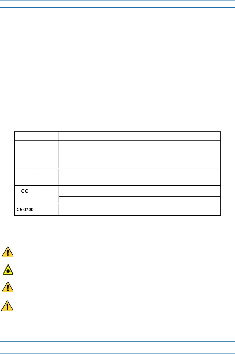
EquipmentSymbolsandCompliance
Table3identifiesmarkingsusedonION‐Ehardwareanddefineswhatthesemarkingsmean,including
requiredusercompliance.Pleaseobservethemeaningsofthelistedsymbolsandcompliancewarnings.
Table3.ComplianceLabels
SymbolComplianceMeaning
—
FCC
Forindustrial(Part20)signalbooster:
WARNING:ThisisNOTaCONSUMERdevice.ItisdesignedforinstallationbyFCCLICENSEESand
QUALIFIEDINSTALLERS.YouMUSThaveanFCCLICENSEorexpressconsentofanFCCLicenseeto
operatethisdevice.Unauthorizedusemayresultinsignificantforfeiturepenalties,including
penaltiesinexcessof$100,000foreachcontinuingviolation.
—
ISED
WARNING:ThisisNOT aCONSUMER device. It is designed for installationbyaninstallerapproved
byanISEDlicensee.YouMUSThaveanISEDLICENCEortheexpressconsentofanISEDlicenseeto
operatethisdevice.
CE
Tobesoldexclusivelytomobileoperatorsorauthorizedinstallers‐ noharmonizedfrequency
bands,operationrequireslicense.Intendeduse:EUandEFTAcountries.
IndicatesconformitywiththeREDdirective2014/53/EUand/orRoHSdirective2011/65/EU.
CEIndicatesconformitywiththeREDdirective2014/53/EUandRoHSdirective2011/65/EUcertified
bythenotifiedbodyno.0700.
HealthandSafetyPrecautions
Observeallcautionsandwarningslistedinthissection
.
Ahighleakagecurrentground(earth)connectiontothePowerSupplyUnit(PSU)isessentialbefore
makinganyotherconnectionstothePSU.
Laserradiation.Riskofeyeinjuryinoperation.Donotstareintothelaserbeam;donotviewthelaser
beamdirectlyorwithopticalinstruments.
Highfrequencyradiationinoperation.Riskofhealthhazardsassociatedwithradiationfromthe
antenna(s)connectedtotheunit.Implementpreventionmeasurestoavoidthepossibilityofclose
proximitytotheantenna(s)whileinoperation.
TheunitistobeusedonlywithCommscope(NECClass2)orLimitedPowerSorceION‐Esubrack,
orequivalent.
ION®‐ESeriesLowPowerCarrierAccessPointInstallationGuide
Page14
M0201AAB
©November2017CommScope,Inc.
InstallingCAPLs
PropertyDamageWarnings
Keepoperatinginstructionswithineasyreachandmakethemavailabletoallusers.
Onlylicenseholdersfortherespectivefrequencyrangeareallowedtooperatethisunit.
Readandobeyallthewarninglabelsattachedtotheunit.Makesurethatallwarninglabelsarekeptina
legiblecondition.Replaceanymissingordamagedlabels.
Makesuretheunit'ssettingsarecorrectfortheintendeduse(refertothemanufacturerproduct
information)andregulatoryrequirementsaremet.Donotcarryoutanymodificationsorfitanyspare
parts,whicharenotsoldorrecommendedbythemanufacturer.
GeneralInstallationSafetyRequirements
Wetconditionsincreasethepotentialforreceivinganelectricalshockwheninstallingorusingelectrically
poweredequipment.Topreventelectricalshock,neverinstalloruseelectricalequipmentinawet
locationorduringalightningstorm.
ThissystemisaRFTransmitterandcontinuouslyemitsRFenergy.Maintainaminimum8‐inch(20cm)
clearancefromtheantennawhilethesystemisoperating.Wheneverpossible,shutdowntheRANbefore
servicingtheantenna.
Donotremovecapsfromanyoftheconnectorsuntilinstructedtodoso.
ACAPLwithaCopperInterfaceisnotdesignedforoutdoorinstallations—itisnotlightningprotected.
However,theantennatowhichtheCopperInterfaceunitsattachcanbeoutdoorsifsuitable
lightning‐protectiondevicesareusedattheantennasite.
GuardAgainstDamagefromElectro‐StaticDischarge
Electro‐StaticDischarge(ESD)candamageelectroniccomponents.TopreventESDdamage,alwayswear
anESDwriststrapwhenworkingwithION‐Ehardwarecomponents.NotallION‐Ehardwarerequires
grounding.ForthoseION‐Ehardwarecomponentsforwhichgroundingisrequired,connecttheground
wireontheESDwriststraptoanearthgroundsourcebeforetouchingtheION‐Ecomponent.Wearthe
wriststraptheentiretimethatyouworkwiththeION‐Ehardware.

M0201AAB
©November2017CommScope,Inc.
ION®‐ESeriesLowPowerCarrierAccessPointInstallationGuide
Page15
InstallingCAPLs
PrepareforInstallation
Dothefollowingbeforebeginninginstallation.
•
Reviewandknowthecautionsin"SafelyWorkingwithION‐EHardware”onpage13.
•
Reviewthesystemdesignplan.
•
Identifytheequipmentinstallationsite.
•
Reviewthepowerrequirementstomakesurethesitecansupportthisinstallation.
•
Mapoutallcableruns.
•
Identifyandobtainalltoolsandmaterialsrequiredtocompletetheinstallation.
CAPLInstallationRules
WheninstallingaCAPL,youmustobservethefollowingrules,whicharealsodocumentedintheinstallation
proceduresincludedinthisinstallationguide.
•
CAPLwithCopperInterface
–
ConnectsviaitsRJ‐45porttoaCATCardintheCAN/TEN
–
EachCATPortcansupporttwoCopperCAPLs,butyoucannotexceedsixCAPLsperCATCard,for
maximumtotalsof24CAPLsinastraightcascadeconfiguration,and32CAPLsperWCSSubrackin
adaisy‐chainconfiguration,butyoumustadheretotheCopperCAPLpoweringrules.
–
Therecanbeatotalof12CAPLsconnectedtoaCATCardinacascadeconfiguration.TheCAPL
connectedtotheCATCardisthePrimaryCAPL,towhichyoucanconnectoneself‐powered
SecondaryCAPL.See"CascadeRules”onpage16.
•
CAPLwithFiberInterface
–
ConnectsviaitsOpticalPort1toanOPTCardintheCAN/TEN
–
Youcanconnectupto4CAPLsperOPTCardforatotalof16.
–
YoucanconnectuptothreeCAPLunits(orcascadedpairs)toOPTCardPorts1‐4.See"Cascade
Rules”onpage16.

ION®‐ESeriesLowPowerCarrierAccessPointInstallationGuide
Page16
M0201AAB
©November2017CommScope,Inc.
InstallingCAPLs
CascadeRules
WhencascadingaSecondaryCAPLoranexternalEthernetdevicesuchasWiFioranIPcamera,youmust
observethefollowingrules,whicharealsodocumentedintheinstallationproceduresincludedinthis
installationguide.
•
Inacascade,theCAPLconnecteddirectlytotheCAN/TENisthePrimaryCAPL,andtheCAPLthat
connectstothePrimaryCAPListheSecondaryCAPL.
•
Thecascadedunitmustusethesametransporttype(CopperorOptical).
–
TocascadetwoOpticalCAPLs,useafiber‐opticcable.
–
TocascadetwoCopperCAPLs,useCat6Acable.Use23AWGCat6Acable;forcablelimitations,see
"Cat6ACableRequirementsforCAPLswithaCopperInterface”onpage39.
•
TheSecondaryCAPLmustgetitspowerthroughtheDCconnector.ForCAPLswithaCopperInterface,
powerovertheCat6Acabletothecascadedunitisnotsupported.
•
YouconnectCAPLswithaCopperInterfacetoaCATCardintheWCSSubrack.EachCATCardhasfour
RJ‐45ports(labeled1‐4).
–
YoucanconnectuptothreeCAPLswithaCopperInterface(orcascadedpairs)toCATCardPorts
1‐3.
–
IfinstalledinCATCardPort4,theCAPLwithCopperInterfacemustbelocallypowered.
•
YouconnectCAPLswithaFiberInterfacetoanOPTCardintheWCSSubrack.EachOPTCardhasfour
10Gbpsports(labeled1‐4)forfiberconnections.
–
Youcanconnectupto4CAPLsperOPTCardforatotalof16.
–
Inacascade,theCAPLconnectedtotheOPTCardisthePrimaryCAPL,towhichyoucanconnectone
SecondaryCAPL.
•
UseoftheAuxiliaryportsinacascadedsystemislimitedasdescribedbelow.
–
ForCAPLswithaFiberInterface,onlyusetheAuxiliaryportonthePrimaryCAPL.
–
ForCAPLswithaCopperInterface,usetheAuxiliaryportonthePrimaryCAPLtoconnectoneofthe
following:
alocallypoweredSecondaryCAPL
anexternalEthernetdevicesuchasWiFioranIPcamera.
•
Thetotal320MHzRFbandwidthissharedbetweenthetwocascadedunits,butcanbesharedunevenly;
thatis,withmorebandwidthgoingtoeitherthePrimaryorSecondaryCAPL—eitherCAPLcantransmit
allthe320MHzRFbandwidthoranysubsetofit.
•
AfterthePrimaryCAPLpowersup,theSecondaryCAPLwillbediscoveredandpoweruponitsown;for
informationonhowaCAPLpowersup,see"PoweringaCAPLandPowerLEDBehavior”onpage9.
RecommendedToolsandMaterial
•
ElectrostaticDischarge(ESD)wriststrap
•
DrillandbitstomountCAPLtoawallorceiling
•
Fibercleaningequipment
•
ifrequiredperlocalpractice,insulatedstrandedcopperwireforchassisground;see"(Optional)Ground
theCAPL”onpage35.
M0201AAB
©November2017CommScope,Inc.
ION®‐ESeriesLowPowerCarrierAccessPoin
t
InstallationGuide
Page17
InstallingCAPLs
DeterminethePowerConsumptionoftheCAPL
UsethepowerconsumptionmatrixinTable4tocalculatepowerconsumptionforaCAPL,where
•
theconsumptionnumbersareattheCAPLpowerinputsanddonotaccountforfeedlosses
•
themaximumconsumptionnumbersinTable4donotincludethepowerconsumedbyanyattached
auxiliarydevices.BothCAPLpowerconsumptionandauxiliarydevicepowermustbeincludedwhen
calculatingfeedlosses.
Table4.CAPLPowerConsumption
ConfigurationVoltageRange(V)TypicalPower(W)MaximumPower(W)
OpticalFiberInterfacewithoutFanKit1,236‐6092102
OpticalFiberInterfacewithFanKit1,236‐6095107
CopperInterfaceandExternalDCPowerwithoutFanKit136‐60100110
CopperInterfaceandExternalDCPowerwithFanKit136‐ 60 103 115
CopperInterfaceandPowerCat6ACablewithoutFanKit <60Vmaximum 100 110
CopperInterfaceandPowerCat6ACablewithFanKit<60Vmaximum103115
1 DoesnotincludeconsumptionofoptionallocalDCsupply.
2 OpticalunitdoesnotincludeSFP+Moduleconsumption.Cansupportupto3W(morewithengineeringconsultation)
maximumtotalSFP+Moduleconsumption.Typicalinstallation(sufficientforSMupto10kmorMM)wouldbe0.8W
typical,1.0WmaxforeachSFP+Module.
DeterminetheCAPLMountingSite
Whendecidingonasuitablemountingsite,observethefollowingrules:
•
TheCAPLissuitableforinstallationindoorsforanyunit.
•
ACAPLwithanOpticalFiberInterfacecanbeinstalledoutsideonlyifithasaFanKit.
•
UsetheweightslistedinTable5todetermineasitethatcanbeartheweightoftheCAPLthatisbeing
installed,where:
–
The“MaximumLiftWeight”isthehighestweightthatmustbeliftedduringinstallation.(Aninstaller
onlyneedstoliftCAPLcomponentsatonetime,notthewhollyconfiguredCAPL.)
–
The“TotalHangingWeight”istheweightoftheCAPL,includingtheweightoftheMountingBracket
andPowerSupply,minustheweightoftheexternalcablesandconnectors,thatthemountingsite
mustbeabletosupport.
•
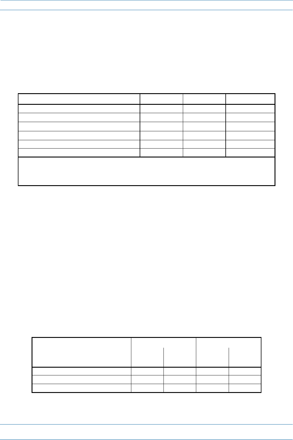
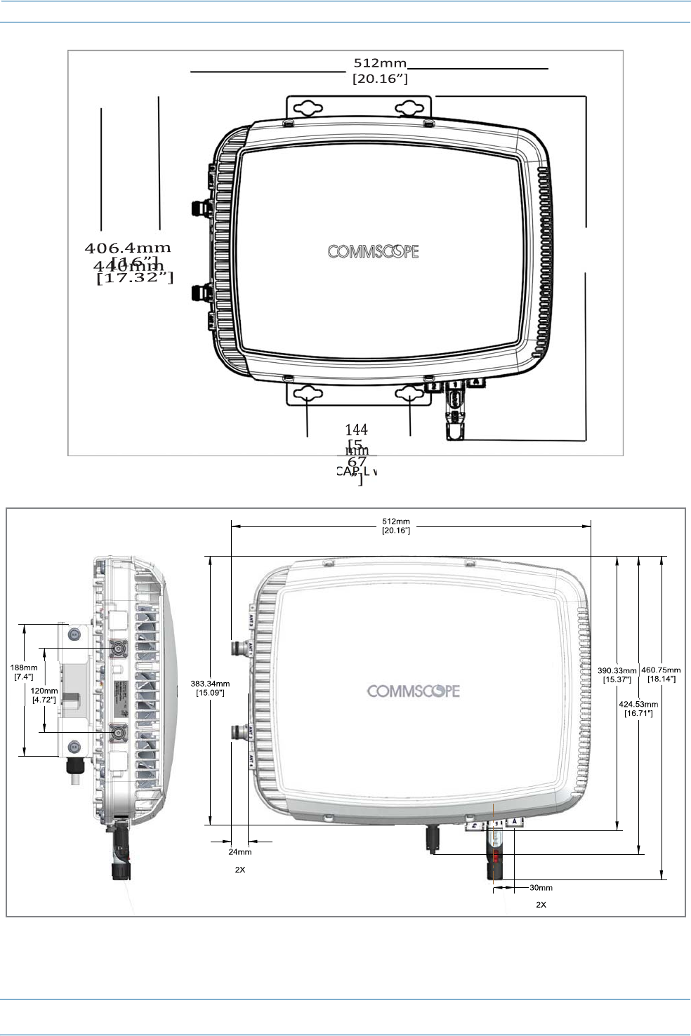
UsethedimensionsshowninFigure3onpage18throughFigure5onpage19.
•
Referalsoto"MountingOrientationforWallMounts”onpage22.
Table5.MaximumCAPLInstallationWeights*
CAPLconfiguredwiththiskit…
MaximumLiftWeightTotalHangingWeight
NoFanKit
kglbs.
WithFanKit
kglbs.
NoFanKit
kglbs.
WithFanKit
kglbs.
FlatMountingBracket10.823.8 11.32510.823.811.325
AC/DCPowerSupplyKit10.723.6 11.224.7 13.22913.730.2
CAPLHybridFiberSpliceBoxKit10.723.6 11.224.7 12.226.912.728
ION®‐ESeriesLowPowerCarrierAccessPointInstallationGuide
Page18
M0201AAB
©November2017CommScope,Inc.
InstallingCAPLs
Figure3.MountingDimensionsforaCAPLwiththeFlatMountingBracketKit
Figure4.MountingDimensionsforaCAPLMountedwiththeCAPLHybridFiberSpliceBoxKit
489.12mm
[19.26”]
[0.94"]
[1.18"]
M0201AAB
©November2017CommScope,Inc.
ION®‐ESeriesLowPowerCarrierAccessPointInstallationGuide
Page19
InstallingCAPLs
Figure5.MountingDimensionsforaCAPLMountedwiththeAC/DCPowerSupplyKit
373.873mm
[14.719"]
[1.181"]
30mm
2X
35.727mm
[1.407"]
447.979mm
188mm
[17.637"]
[7.402"]
24.106mm
[0.949"]
399.8mm
[15.74"]
31.5mm
[1.24"]
[18.489"]
469.62
104.73mm
[4.123"]
158.42mm
[6.237"]
87.44mm
36.5mm
[1.437"]
48.69mm [3.443"]
[1.917"]
[4.724"]
120mm
[15.787"]
401mm

ION®‐ESeriesLowPowerCarrierAccessPointInstallationGuide
Page20
M0201AAB
©November2017CommScope,Inc.
InstallingCAPLs
GeneralMountingCautions
ThefollowingcautionsapplytoallCAPLinstallations;theremaybeothermountingcautionsapplicabletoa
specificmountingoption,whichwillbedefinedintheapplicablemountingprocedure.
AttachallCAPLssecurelytoastationaryobjectasdescribedinthisinstallationguide.
Tomaintainproperventilation,keepatleast76mm(3‐inch)clearancearoundtheCAPL.
TheinstallationsitemustbeabletobeartheweightoftheCAPL;seeTable5onpage17.
UnpackandInspecttheCAPLandOptionalAccessories
1
Inspecttheexterioroftheshippingcontainer(s)forevidenceofroughhandlingthatmayhavedamaged
thecomponentsinthecontainer.
2
Unpackeachcontainerwhilecarefullycheckingthecontentsfordamageandverifywiththepackingslip.
3
Ifdamageisfoundorpartsaremissing,fileaclaimwiththecommercialcarrierandnotifyCommScope
TechnicalSupport(see"DCCSGlobalTechnicalSupport”onpage53).Savethedamagedcartonsfor
inspectionbythecarrier.
4
Saveallshippingcontainersforuseiftheequipmentrequiresshipmentatafuturedate.
MounttheCAPL
TheCAPLissuitableforindoorandoutdoorinstallationsasfollows:
•
Indoors—AllversionsoftheCAPLcanbeinstalledindoors.
•
Outdoors—
–
OnlyOpticalFiberCAPLswiththeoptionalFanKitcanbeinstalledoutdoors.
–
DonotinstallCopperCAPLs(thatis,haveCat6Acabling)outdoorsastheyarenotdesignedfor
outdoortemperatures,nordotheyhaverequiredlightningprotection.
Mountinginstructionsaredividedintothesectionslistedbelow.
•
Thefollowingsectionsapplytoallinstallations.
–
"GeneralMountingCautions”onpage20
–
"MountingOrientationforWallMounts”onpage22.
•
Followthemountinginstructionsthatareappropriateforthisinstallation:
–
"Flat‐SurfaceMountaCAPL”onpage21
–
"WallMountaCAPLUsingaFlatMountingBracketKit”onpage24
–
"CeilingMountaCAPLwithaFanKit”onpage34
–
"WallMountaCAPLUsingaAC/DCPowerSupplyKit”onpage31.
M0201AAB
©November2017CommScope,Inc.
ION®‐ESeriesLowPowerCarrierAccessPointInstallationGuide
Page21
InstallingCAPLs
Flat‐SurfaceMountaCAPL
YoucanplaceaCAPLonaflatsurface,suchasashelf,desk,cabinet,aboveaceiling,oranyotherhorizontal
surfacethatallowsstableplacement.
IfyoumounttheCAPLonaflatsurface,inadditiontotheruleslistedin"GeneralMountingCautions”on
page20,youmustalsoobservethefollowingrulesthatarespecifictoaflat‐surfacemount.
Tomaintainproperventilation,keepatleast76mm(3‐inch)clearancearoundtheCAPL.
DonotstackCAPLsontopofeachother.
AlwayssecuretheCAPLtothemountingsurface.
IfaCAPLwithoutaFanKitisflat‐surfacemounted,theminimumclearanceabovetheCAPLis203.2
millimeters(8inches).
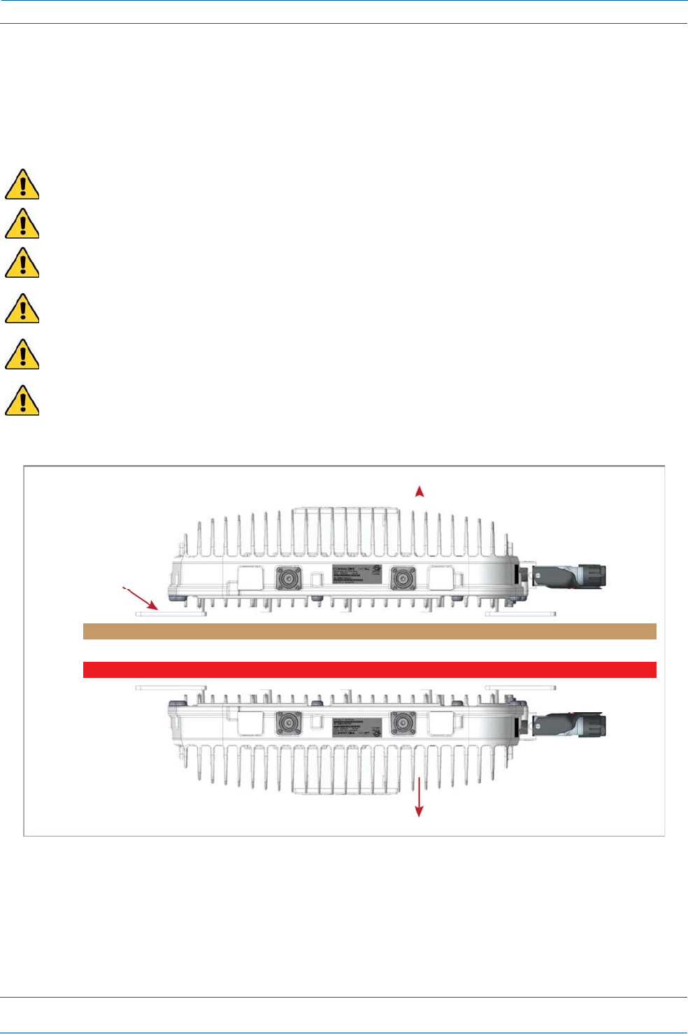
AlwaysmounttheCAPLwithitsmountingoptionfacingdownagainstthemountingsurface,andthe
enclosurefinsfacingup;seeFigure6.
IfyouaremountingtheCAPLaboveaceiling,itsantennasmustprotrudebelowtheceiling.Thatis,the
CAPLwillbeabovetheceiling,butanyconnectedWiFiunitsorIPcameraswillbemountedbelowthe
ceiling;seeFigure6.
Figure6.CAPLOrientationinFlat‐SurfaceMounting
AfteryoumounttheCAPLonaflatsurface,followthestepsin"ConnecttheCAPLCables”onpage36.
Finsfacingup
Flat‐MountingBracket
optionissecuringthe
CAPLtotheflat
surface.
FlatSuface
IftheCAPLdoesnothaveaFanKit,donotFlat‐SufaceMountwiththeCAPLFinsfacingdown.
FinsFacingdown
ION®‐ESeriesLowPowerCarrierAccessPointInstallationGuide
Page22
M0201AAB
©November2017CommScope,Inc.
InstallingCAPLs
WallMountaCAPL
ThefollowingsectionsprovidetheinstallationmethodologyandstepsrequiredtomountaCAPLtoawall.
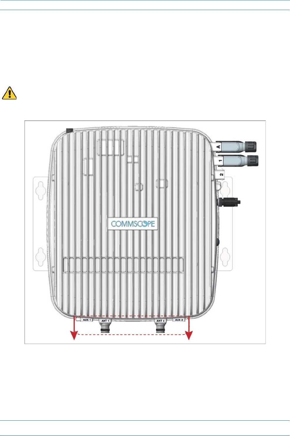
MountingOrientationforWallMounts
WhenwallmountingaCAPL,therecommendationsshouldbeobserved.
•
WallMountOrientationforaCAPLwithoutaFanKit
ACAPLthatdoesnothaveaFanKitispassivelycooled.YoushouldthereforemountaCAPLthatdoesnot
haveaFanKitwiththeANTportspointingdown(seeFigure7).Otherwise,theCAPLwillhaveareduced
maximumoperatingtemperatureof33°C(91°F).
Figure7.MountingOrientationforaCAPLwithouttheOptionalFanKit(FlatMountingBracketShown)
ANTconnectorspointingdown
M0201AAB
©November2017CommScope,Inc.
ION®‐ESeriesLowPowerCarrierAccessPointInstallationGuide
Page23
InstallingCAPLs
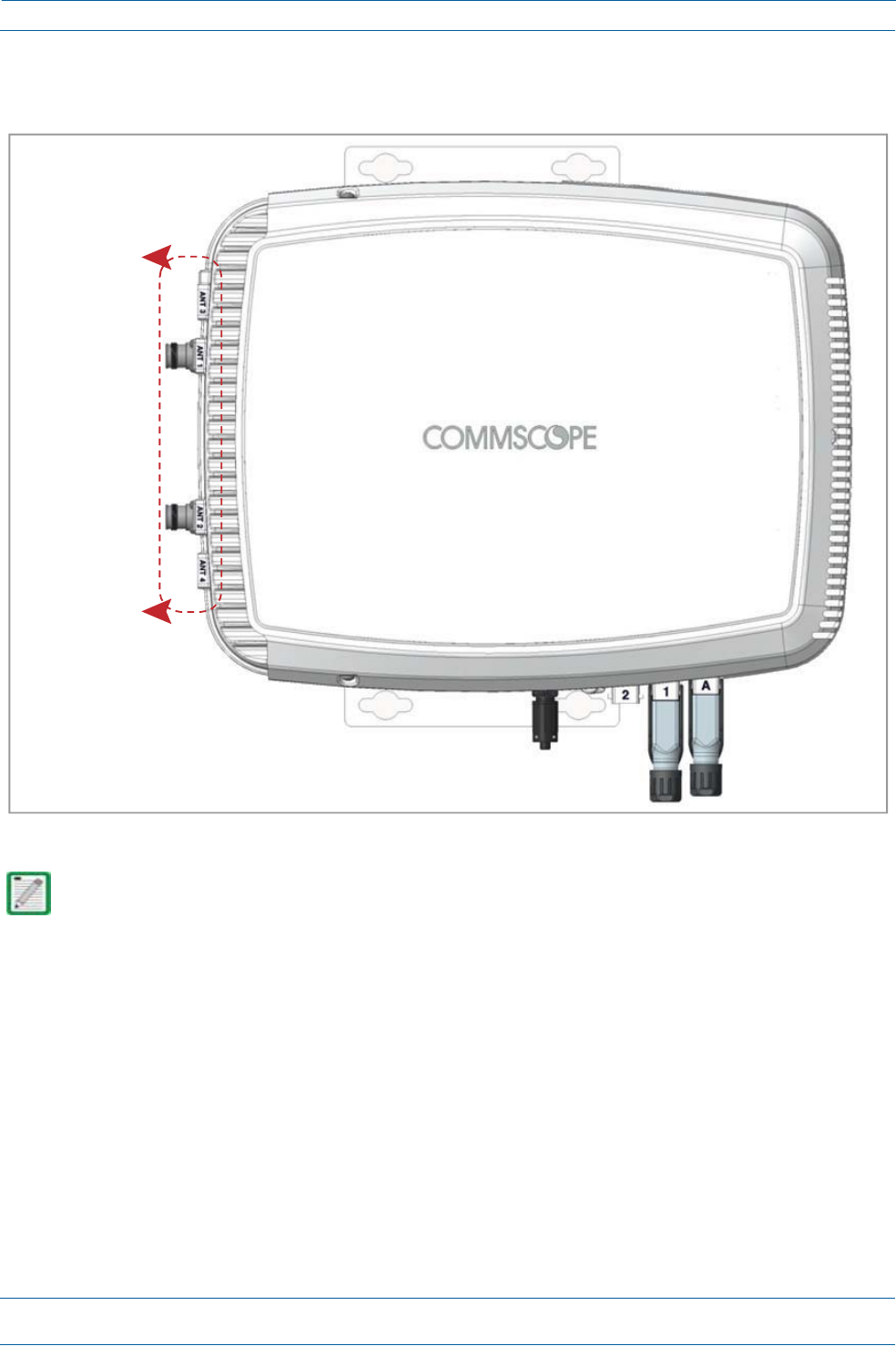
•
WallMountOrientationforaCAPLwithaFanKit—ToallowforoptimalaccesstotheCAPLcables,it
isrecommendedthataCAPLwiththeFanKitoptionbemountedwiththeANTportsarepointingtothe
left;seeFigure8onpage23.
Figure8.MountingOrientationforaCAPLwiththeOptionalFanKit(FlatMountingBracketShown)
Mountingrequirementsforflatsurfacesaredescribedin"Flat‐SurfaceMountaCAPL”onpage21.
Ceiling‐mountrequirementsaredescribedin"CeilingMountaCAPLwithaFanKit”onpage34.
ANTconnectors
pointingtotheleft
ION®‐ESeriesLowPowerCarrierAccessPointInstallationGuide
Page24
M0201AAB
©November2017CommScope,Inc.
InstallingCAPLs
WallMountaCAPLUsingaFlatMountingBracketKit
1
Followthestepsin"UnpackandInspecttheCAPLandOptionalAccessories”onpage20.
2
Refertoandobserveallcautionslistedin"GeneralMountingCautions”onpage20.
3
Referto"DeterminetheCAPLMountingSite”onpage17todeterminethemountinglocation,whichmust
beabletosupporttheweightanddimensionsoftheCAPL.
4
Referto"MountingOrientationforWallMounts”onpage22todeterminethemountingorientationofthe
CAPL.
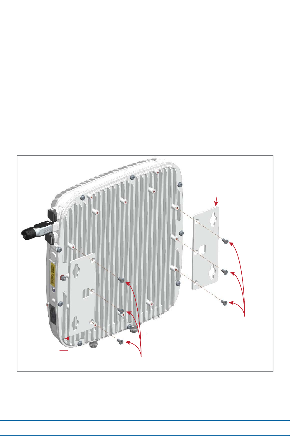
5
AttachthetwomountingbracketstothebackoftheCAPLenclosureasdescribedbelowandasshownin
Figure9(CAPLwithaFanKit)andFigure10onpage25(CAPLwithoutFanKit).
a
UsethreeoftheM6‐1.0x14mmscrewsthatcamewiththeFlatMountingBracketKittoattachtheleft
ortopmountingbrackettothethreecorrespondinghorizontalorverticalM6‐1.0mountingtapson
thebackoftheCAPLchassis.
b
UsethreeoftheM6‐1.0x14mmscrewsthatcamewiththeFlatMountingBracketKittoattachthe
rightorbottommountingbrackettothethreecorrespondinghorizontalorverticalM6‐1.0mounting
tapsonthebackoftheCAPLchassis.
Figure9.CAPL(NoFanKit)withFlatMountingBracketKit(PN7774353‐xx)
OneMountingbracket
inhorizontalposition
Three
M6‐1.0x14mm
screws
OneMountingbracket
inhorizontalpositionThreeM6‐1.0x14mmscrews
NOTE:InstallaCAPLwith
aFanKithorizontally.
M0201AAB
©November2017CommScope,Inc.
ION®‐ESeriesLowPowerCarrierAccessPointInstallationGuide
Page25
InstallingCAPLs
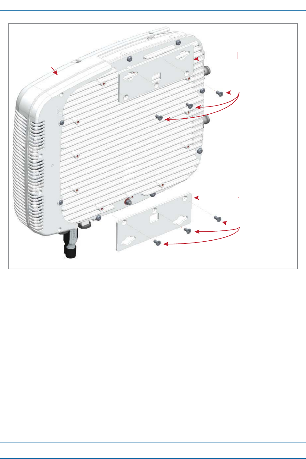
Figure10.CAPLwithaFanKitandFlatMountingBracketKit(PN7774353‐xx)
6
Usefour5/16‐inchorM8lagscrews(orwhateverscrewtypeisappropriateforthematerialtowhichthe
CAPListomountedon)tomounttheCAPLtothewall.
7
Followthestepsin"(Optional)GroundtheCAPL”onpage35ifgroundingisrequiredorpreferred.
8
Followthestepsin"ConnecttheCAPLCables”onpage36.
FanKit
OneMountingbracket
inverticalposition
Three
M6‐1.0x14mm
screws
OneMountingbracket
inverticalposition
Three
M6‐1.0x14mm
screws
NOTE:InstallaCAPLthatdoesnothaveaFanKitverically.
ION®‐ESeriesLowPowerCarrierAccessPointInstallationGuide
Page26
M0201AAB
©November2017CommScope,Inc.
InstallingCAPLs
WallMountaCAPLUsingaCAPLHybridFiberSpliceBoxKit
1
Followthestepsin"UnpackandInspecttheCAPLandOptionalAccessories”onpage20.
2
Referto"DeterminetheCAPLMountingSite”onpage17todeterminethemountinglocation,whichmust
beabletosupporttheweightanddimensionsoftheCAPL.
3
Referto"MountingOrientationforWallMounts”onpage22todeterminethemountingorientationofthe
CAPL.
4
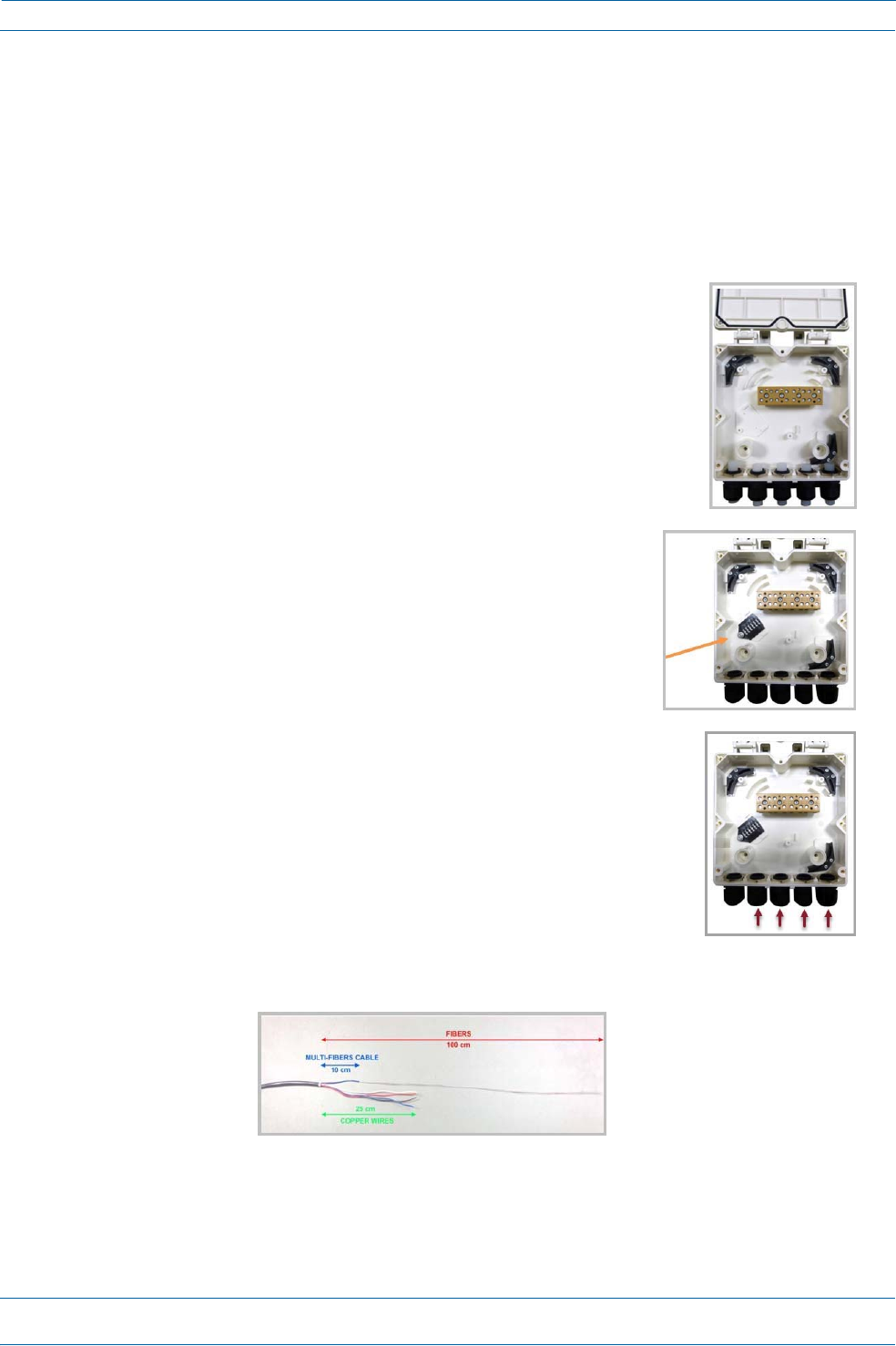
AssemblethecablesintheHybridFiberSpliceBox.
aOpentheHybridFiberSpliceBox and remove the installation ki
t
thatisinside.
bUsingthepartsfromtheHybridFiberSpliceBox,insertthe
SpliceHolderandfastenitusingaPTK30x6screwandoneM4
washer.
cFromtheCAPLHybridFiberSpliceBoxKit,insertFiberPatch
Cordinoneofthecableglandsindicatedinthegraphictothe
right.
dStriptheinsulationofthecompositecablefor100cmandthefibersfor90cm,andthenshorten
thecoppercablesto25cm.
M0201AAB
©November2017CommScope,Inc.
ION®‐ESeriesLowPowerCarrierAccessPointInstallationGuide
Page27
InstallingCAPLs
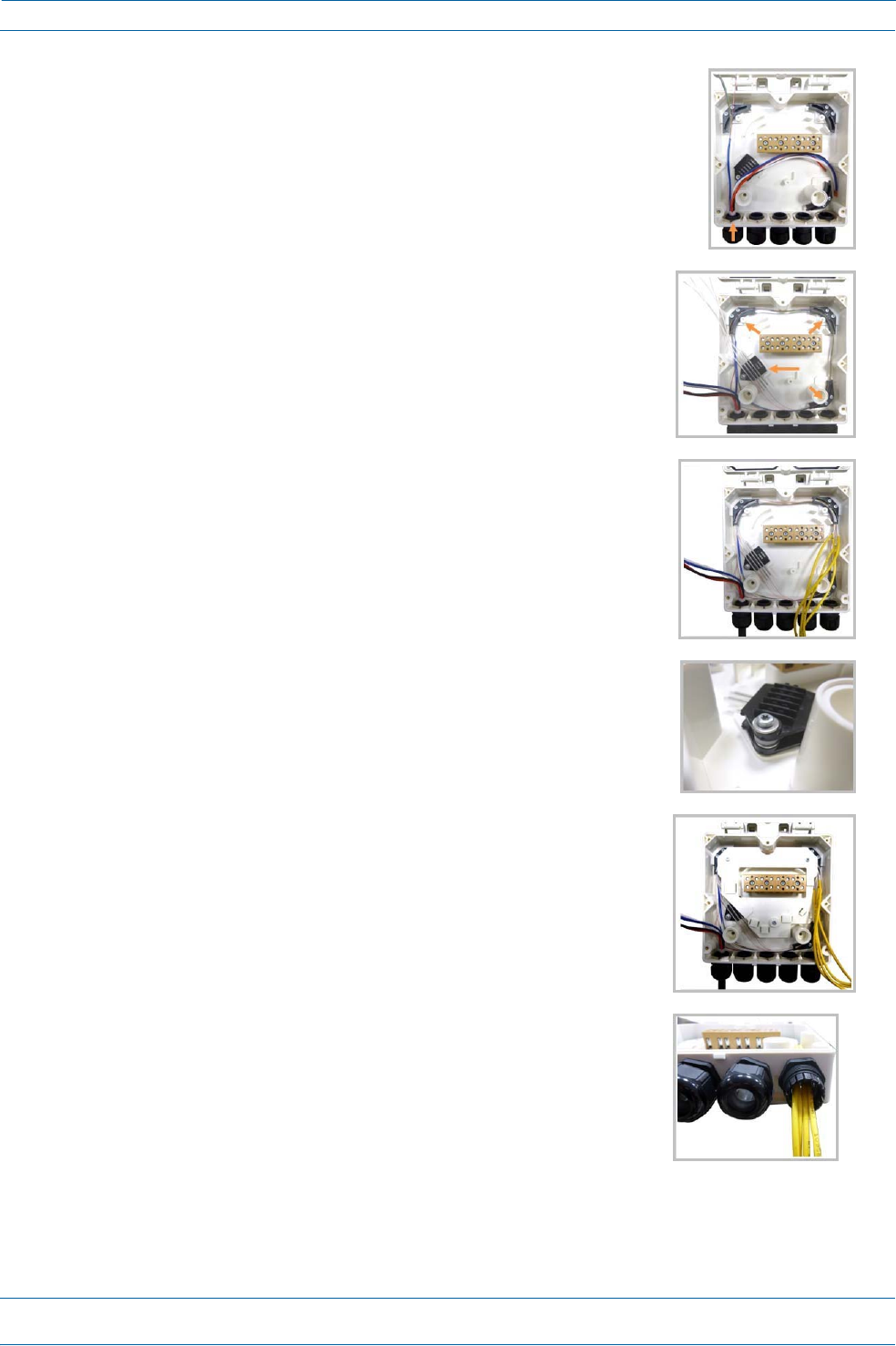
eInsertthecompositecableinthefirstcableglandandseparate
themulti‐fiberscablefromthecopperwires.Itisnecessaryto
removethenuttoperformthisaction.Thecablemustbefed
throughthenutanditmustberetightenedoncefinished.
fBendthesplicedfibersusingthecornerguidesandfixthe
splicestothespliceholder.
gBendtheopticalcablesasshowinthepicturetotheright.
hIfasecondspliceholderisneeded,itcanbeassembledusingthe
M4insulatingwasherandtwoM4plainwashers,asshownto
theright.TherequiredscrewisaPTK30x12.
iMounttheinternalsupportSpliceBoxION‐URUusingthree
PTK30x6screws.
jRemovethesealingnutandrubberofthecableglandandinsert
theopticalcables.
ION®‐ESeriesLowPowerCarrierAccessPointInstallationGuide
Page28
M0201AAB
©November2017CommScope,Inc.
InstallingCAPLs
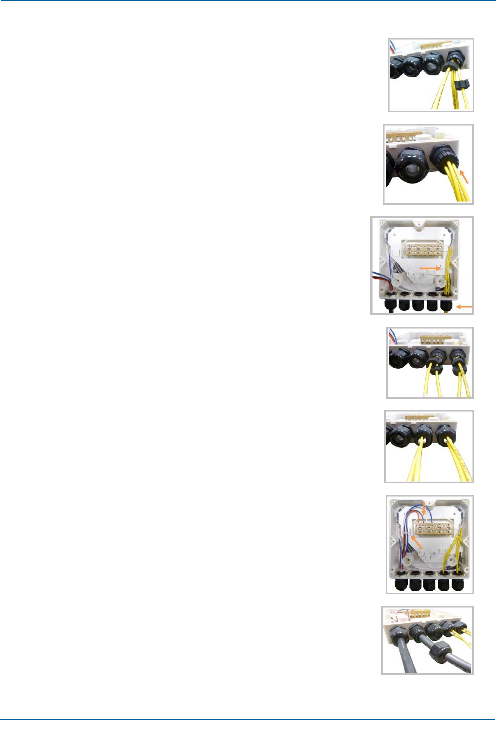
kPlaceeachcableintooneofthegroovesofthesealinsert.
lPressthesealinsertintotheclampringopening.
mFixtheopticalcablesinsidetheboxusingonecabletieandtight
thesealingnut.
nItispossibletoseparatetheopticalcablesandusetwodifferent
cableglands.Removethesealingnutandrubberoneachcable
gland.
oCloseallunusedgrooveswiththeplasticcylinders,nomatterif
oneortwocableglandsareused.
pInsertthecopperwiresinthefirstmultipleterminalconnectors.
Seemarkingsontheinternalsupport.Thenfastenthecopper
cablesinsidetheboxusingonecabletie.
qRemovethesealingnutandinserttheRemoteUnitsupplycable
andtightenthesealingnut.

M0201AAB
©November2017CommScope,Inc.
ION®‐ESeriesLowPowerCarrierAccessPointInstallationGuide
Page29
InstallingCAPLs
rConnectthesupplycabletotheterminalstripandfixitinsidethe
boxusingonecabletie.Itispossibletoconnectasecondsupply
cable.
sIncaseofusingremoteunitVdc/100connectthesupplycableas
shownbesides.Refertomarkingsontheinternalsupport.
ION®‐ESeriesLowPowerCarrierAccessPointInstallationGuide
Page30
M0201AAB
©November2017CommScope,Inc.
InstallingCAPLs
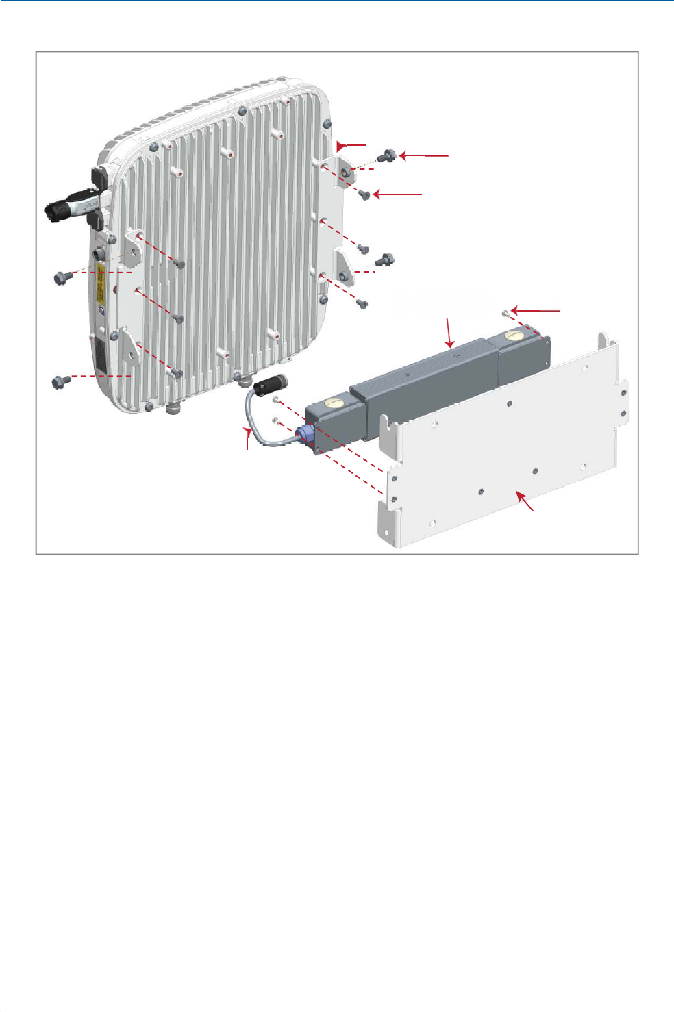
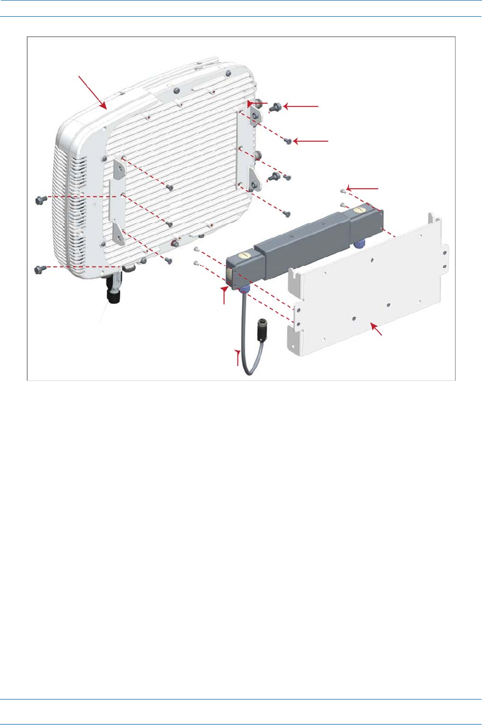
5
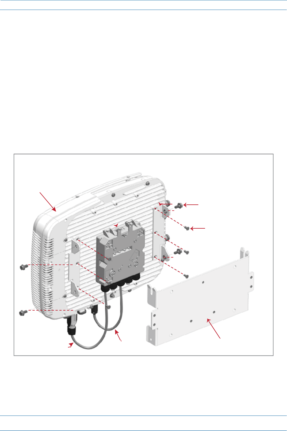
AssembleandmounttheCAPLHybridFiberSpliceBoxKitandtheCAPL,asdescribedbelowandas
showninFigure11,whichshowsaCAPLwithFanKit(installationforaCAPLwithoutaFanKitisthe
same).
a
AttachtheHybridFiberSpliceBoxtotheWallBracketwiththethreecaptivescrewsalreadyinstalled
intheSpliceBox.
b
AttachtheassembledHybridSpliceBoxandWallMountingBrackettotheselectedmountinglocation.
c
UsethesixM6‐1.0x14mmscrewstoattachthetwoAngledMountingBracketstotheWallMounting
Bracket.
i
Putthetoptwoflange‐headscrewshalfwayintothemountingbrackets,andthenusethemto
“hang”theCAPLintheWallMountingBracket.
ii
Attachthebottomtwoflange‐headscrews.
iii
Tightenallfourscrews.
d
FromtheCAPLHybridFiberSpliceBoxKit:
i
AttachtheLocalPowerJumpertotheCAPLpowerconnector.
ii
AttachtheFiberPatchCordtotheCAPLPort1;theotherendwasattachedinStep4c(page26)
tooneofthecableglands.
Figure11.CAPLwithFanKit,CAPLMountingBracketKit,andCAPLHybridFiberSpliceBoxKit
6
Followthestepsin"(Optional)GroundtheCAPL”onpage35ifgroundingisrequiredorpreferred.
7
Followthestepsin"ConnecttheCAPLCables”onpage36.
OneHybrid
FiberSpliceBox
TwoAngled
MountingBrackets
FanKit
FourM8x16flange‐headscrews
SixM6‐1.0x14mmscrews
OneFiber
PatchCord
OneLocal
PowerJumper
OneWallMountingBracket

M0201AAB
©November2017CommScope,Inc.
ION®‐ESeriesLowPowerCarrierAccessPointInstallationGuide
Page31
InstallingCAPLs
WallMountaCAPLUsingaAC/DCPowerSupplyKit
1
Refertoandobserveallcautionslistedin"GeneralMountingCautions”onpage20.
2
Referto"DeterminetheCAPLMountingSite”onpage17todeterminethemountinglocation,whichmust
beabletosupporttheweightanddimensionsoftheCAPL.
3
Referto"MountingOrientationforWallMounts”onpage22todeterminethemountingorientationofthe
CAPL.
4
Followthestepsin"UnpackandInspecttheCAPLandOptionalAccessories”onpage20.
5
AssembleandmounttheAC/DCPowerSupplyKitandtheCAPL,asdescribedbelowandasshownin
Figure12onpage32(CAPLwithoutFanKit)andFigure13onpage33(CAPLwithFanKit).TheLocal
PowerJumperCableAssemblywillbeconnectedtotheAC/DCPowerSupplyJunctionBoxatthefactory.
a
UsethefourscrewstoattachtheAC/DCPowerSupplyassemblytotheWallMountingBracket.
b
AttachtheassembledAC/DCPowerSupplyKitandWallMountingBrackettotheselectedmounting
location.
c
UsethesixM6‐1.0x14mmscrewstoattachthetwoAngledMountingBracketstotheWallMounting
Bracket.
i
Putthetoptwoflange‐headscrewshalfwayintothemountingbrackets,andthenusethemto
“hang”theCAPLintheWallMountingBracket.
ii
Attachthebottomtwoflange‐headscrews.
iii
Tightenallfourscrews.
ION®‐ESeriesLowPowerCarrierAccessPointInstallationGuide
Page32
M0201AAB
©November2017CommScope,Inc.
InstallingCAPLs
Figure12.CAPL(NoFanKit)withAC/DCPowerSupplyKit(PN7775087‐xx)
andCAPLMountingBracketKit(7774354‐xx)
TwoAngled
MountingBrackets
FourM8x16flange‐headscrews
SixM6‐1.0x14mmscrews
AC/DCPowerSupplyUnit
withJunctionBoxFour
M6‐1.0x14mm
screws
LocalPower
JumperCable
OneWall
MountingBracket
M0201AAB
©November2017CommScope,Inc.
ION®‐ESeriesLowPowerCarrierAccessPointInstallationGuide
Page33
InstallingCAPLs
Figure13.CAPLwithFanKitandwithAC/DCPowerSupplyKit(PN7775087‐xx)
andCAPLMountingBracketKit(PN7774354‐xx)
TwoAngled
Mounting
Brackets
FanKit
FourM8x16flange‐headscrews
SixM6‐1.0x14mmscrews
FourM4x8screws
AC/DCPower
SupplyUnit
withJunctionBox
OneWall
MountingBracket
LocalPower
Jumper Cable
ION®‐ESeriesLowPowerCarrierAccessPointInstallationGuide
Page34
M0201AAB
©November2017CommScope,Inc.
InstallingCAPLs
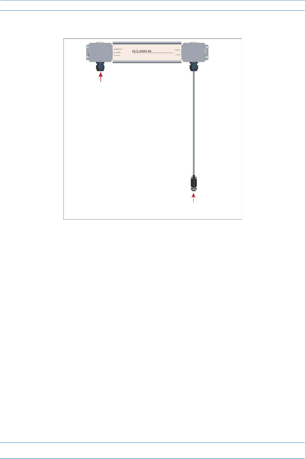
6
ConnecttheLocalPowerJumperCable(shownbelow)totheCAPL36to60VdcPowerconnector(see
"CAPLwithaCopperInterfaceandPowerCat6ACable”onpage8).
7
Followthestepsin"(Optional)GroundtheCAPL”onpage35ifgroundingisrequiredorpreferred.
8
Followthestepsin"ConnecttheCAPLCables”onpage36.
CeilingMountaCAPL
YoucanmountaCAPLaboveorbelowaceiling.WheninstallingaCAPLbelowaceiling,theuseofthe
optionalFanKitdetermineshowtheCAPLcanbeceilingmounted,asdescribedinthefollowingsections.
•
"CeilingMountaCAPLwithoutaFanKit”onpage34
•
"CeilingMountaCAPLwithaFanKit”onpage34.
IfyoumounttheCAPLabovetheceiling,itsantennasmustprotrudebelowtheceiling.
CeilingMountaCAPLwithoutaFanKit
ACAPLthatdoesnothaveaFanKitshouldonlybeinstalledaboveasuspendedceilingonaflatsurface,using
thestepsin"Flat‐SurfaceMountaCAPL”onpage21.
CeilingMountaCAPLwithaFanKit
1
Followthestepsin"UnpackandInspecttheCAPLandOptionalAccessories”onpage20.
2
Refertoandobserveallcautionslistedin"GeneralMountingCautions”onpage20.
3
Referto"DeterminetheCAPLMountingSite”onpage17todeterminethemountinglocation,whichmust
beabletosupporttheweightanddimensionsoftheCAPL.
GlandforincomingACpower
LocalPowerJumperthatconnectsto
CAPL36to60VdcPowerconnector
M0201AAB
©November2017CommScope,Inc.
ION®‐ESeriesLowPowerCarrierAccessPointInstallationGuide
Page35
InstallingCAPLs
4
Followthestepsinoneofthefollowingsectionsthatapplytosecuringthedesiredmountingbracketto
theCAPL:
•
"WallMountaCAPLUsingaFlatMountingBracketKit”onpage24
•
"WallMountaCAPLUsingaCAPLHybridFiberSpliceBoxKit”onpage26
•
"WallMountaCAPLUsingaAC/DCPowerSupplyKit”onpage31
5
Usefour5/16‐inchorM8lagscrews(orwhateverscrewtypeisappropriateforthematerialtowhichthe
CAPListomountedon)tomounttheCAPLtotheceiling.
6
Followthestepsin"(Optional)GroundtheCAPL”onpage35ifgroundingisrequiredorpreferred.
7
Followthestepsin"ConnecttheCAPLCables”onpage36.
(Optional)GroundtheCAPL
FollowthestepsbelowtogroundtheOPAonlyifgroundingisrequiredinyourlocalityoriftheinstallation
plansrequiretheCAPLbegrounded.ThedifferentCAPLinstallationprocedureswilltellyouwhentoground
theCAPL.
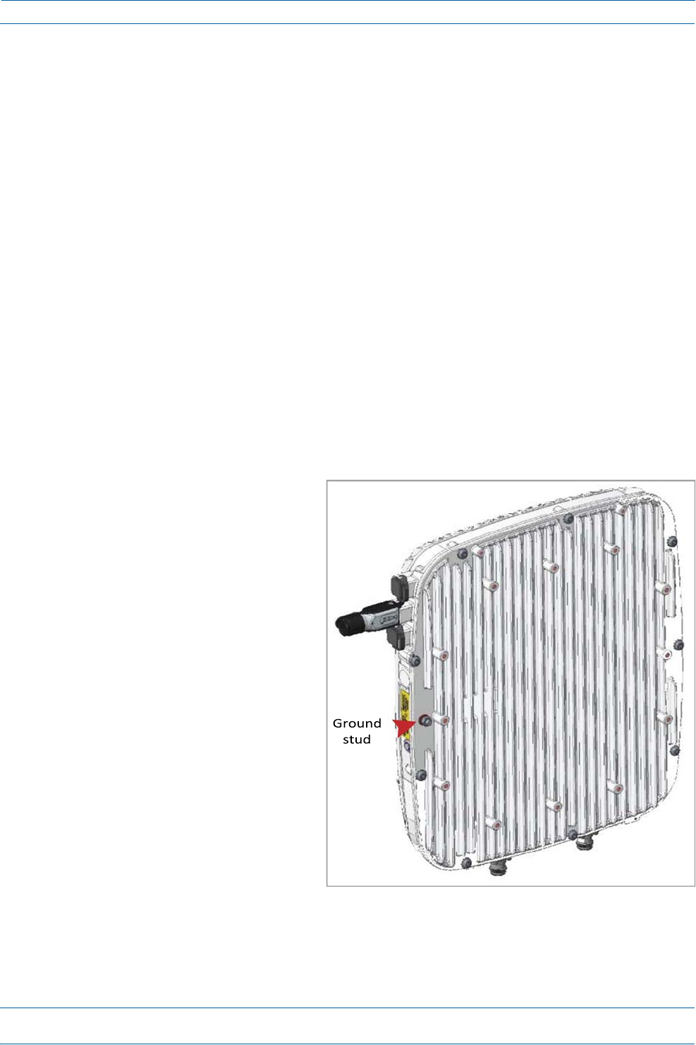
NOTE:TheCAPLisequippedwithanM6groundingstudlocatedonthebackoftheunit;however,
groundingisnotnecessary.CAPLsareclassifiedaslow‐voltagedevicesanddonothaveinternal
powersupplies.CommScoperecommendscheckingyourlocalandnationalelectricalcodesto
determineifgroundingisarequirement.
1
Obtainalengthof#18AWG(1.00mm)
insulatedstrandedcopperwireforuseas
achassis‐groundingwire.
2
Terminateoneendofthewirewitharing
terminal.
3
Locatethechassis‐groundstudattherear
oftheCAPLenclosure.
4
RemovetheKepsnutfromthe
chassis‐groundstud.
5
Attachtheringendofthewiretothe
chassisgroundstud,asshownbelow.
6
UsetheKepsnutremovedinStep4to
securethegroundwiretothe
chassis‐groundstud.
7
Routethefreeendofthechassis
groundingwiretoanapproved(perlocal
codeorpractice)earthgroundsource.
ION®‐ESeriesLowPowerCarrier
A
ccessPointInstallationGuide
Page36
M0201AAB
©November2017CommScope,Inc.
InstallingCAPLs
ConnecttheCAPLCables
ThetypeofcablesusedandhowtheCAPLconnectsintothesystemisdependentontheCAPLtype.Follow
thecablinginstructionsthatapplytotheunittypethatyouareinstalling.
•
"CableaCAPLwithanOpticalFiberInterface”onpage36
•
"CableaCAPLwithaCopperInterface”onpage39.
CableaCAPLwithanOpticalFiberInterface
Figure14identifiestheconnectorsonaCAPLwithanOpticalFiberInterface;correspondingcablesand
connectorsareshown.Fordetailsontheports,see"CAPLwithanOpticalFiberInterface”onpage6.
CAUTION!Donotremovecapsfromanyoftheconnectorsuntilinstructedtodoso.
Figure14.ConnectorsonaCAPLwithanOpticalFiberInterface
M0201AAB
©November2017CommScope,Inc.
ION®‐ESeriesLowPowerCarrier
A
ccessPointInstallationGuide
Page37
InstallingCAPLs
1
ContactyourlocalCommScopesalesrepresentativetoobtainthefollowingcomponents,asrequired,for
thisinstallation.
•
Pertheinstallationplan,obtaineitherSingleModeFiber(SMF)orMultiModeFiber(MMF)thatisof
sufficientlengthtoreachfromtheCAPLtotheION‐ECAN/TEN
•
ObtainatleastoneOpticalOCTISKit(PN7770612).AllinstallationsrequireoneOpticalOCTISKit.If
cascadingaSecondaryCAPL,asecondOpticalOCTISKitisrequired.
•
ObtainanSFP+Modulethatisappropriateforthisinstallation.Table6identifiestheavailableSFP+
Modulesandthemaximumrangeforeach.
Table6.SupportedSFP+Modules
CommScopePNDescriptionMaximumRangeNotes
7660511 ION‐ESFP+,10GBase‐SRR,MultiModeOM3OM4
300m400m
OneplacedintheTENandpairedwithanotherintheCAN
7680813 ION‐ESFP+,10GBase‐LR,SingleMode10kmOneplacedintheTENandpairedwithanotherintheCAN
•
IfconnectinganexternalEthernetdevicesuchasWiFiorIPcamera,anEthernetOCTISKit
(PN7760652RJ‐45)andappropriateCATcablefortheprotocoltowhichtheCAPLwillconnect.(This
modelsupportsa1000BASE‐Tand802.3atClass4PoweroverCat6AEthernetconnection.Follow
therulesin"Cat6ACableRequirementsforCAPLswithaCopperInterface”onpage39,allCat6Acable
requirementsandcable‐lengthrulesbetweenaPrimaryandSecondaryCAPLalsoapplyto
connectinganexternalEthernetdevice.)
–
AsingleCAPLcansupportoneauxiliaryEthernetdevice.
–
AcascadedCAPLpaircansupportoneauxiliarydevice.
2
ConnecttheCAPLANT1and/orANT2connectortoapassiveRFantenna.
a
Obtain50 coaxialcablesthatareofsufficientlengthtoreachfromtheCAPLtothepassiveantenna.
Theendofthe50 coaxialcablethatwillconnecttotheANTconnectorcanbeeitherapush‐pull
connectororathreadedconnector.
b
Installthepassiveantennasperthemanufacturer’sinstallationinstructions.IfconnectingbothANT
connectors,youwillconnecttheCAPLtoeithertwoseparateexternalpassiveantennasortotwo
portsonacross‐polarizeddualantenna.EachconnectorsupportstwoRFbands(seeTable7).
Table7.MappingFrequencyBandstoAntennas
FrequencyBandBandCombinationAntennaPort
AWS1700/LTE230017Eand231
AWS1700/LTE230017Eand232
GSM1800/UMTS2100/LTE2600 18 and26 1
GSM1800/UMTS2100/LTE2600 21and26 2
AWS1700/PCS1900 17Eand19 1
AWS1700/PCS190017Eand192
c
RemovetheIP67/EMIblankplugfromtheANT1/2connector.

ION®‐ESeriesLowPowerCarrierAccessPointInstallationGuide
Page38
M0201AAB
©November2017CommScope,Inc.
InstallingCAPLs
d
Connectthepassivemulti‐bandantennatotheANT1orANT2connectorusingcoaxialcablewiththe
leastamountoflosspossible.
•
Ifthe50 coaxialcablehasapush‐pullconnector,makesurethecableisseatedfirmlyintheANT
1orANT2connector.
•
Ifthe50 coaxialcablehasathreadedconnector,torquetheconnector5N‐m(3.69ft‐lb).Donot
over‐tightentheconnector.
e
Connecttheotherendofthe50 coaxialcabletothepassiveantennainstalledinbonpage37.
3
Ifnecessary,repeat2onpage37toconnecta50 coaxialcabletotheotherANTconnector.
4
ConnecttheCAPLOpticalPort1asappropriateforthisinstallation.Notethemaximumrangelistedin
Table5onpage17.
a
RemovethedustcapfromtheCAPLOpticalPort1connectorandtheconnectorsontheSMForMMF.
b
FollowthelocalcleaningtechniquetocleanOpticalPort1.
c
CleantheconnectorsontheSMForMMFfollowingthefibersupplier’srecommendations.
d
InstalltheSFP+connectorandOpticalOCTISKitontheendoftheSMForMMFthatwillconnectto
theCAPL,andthenconnectthatendofthefibertotheCAPLOpticalPort1connector.(Refertothe
technicaldatasheetthatshipswiththeOCTISKitforfurtherinformation.)
e
ConnecttheotherendoftheSMForMMFtoanopenportontheOPTCard.
IfinstallingaCAPLwiththeCAPLHybridFiberSpliceBoxKit(PN7774354‐xx),theopticalfiberwillbe
hangingfromtheHybridFiberSpliceBox.
5
Ifappropriateforthisinstallation,connecttheOpticalPort2connector.Notethemaximumrangelisted
inTable5onpage17.
a
RaisetheleverontheEMI/IP67caponOpticalPort2connectorandremovethecap.
b
RemovethecapsfromtheconnectorsontheSMForMMF.
c
FollowthelocalcleaningtechniquetocleanOpticalPort2.
d
CleantheconnectorsontheSMForMMFfollowingthefibersupplier’srecommendations.
e
InstalltheSFP+andOpticalOCTISKitontheendofthefiberthatwillconnecttotheCAPL,and
connectthatendoftheSMForMMFtotheCAPLOpticalPort2connector.(Refertothetechnicaldata
sheetthatshipswiththeOCTISKitforfurtherinformation.)
f
ConnectotherendoftheSMForMMFtoOpticalPort1onthecascadedCAPL.
6
(Optional)PortA(Auxiliaryport)providesaconnectionforexternalEthernetdevicessuchasWiFiand
IPcameras.CablePortAasappropriateforthisinstallation.
PortAmustbepluggedifnotinuse.
a
RaisetheleverontheEMI/IP67caponPortAandremovethecap.
b
InstalltheEthernetOCTISKitontheendofthecablethatwillconnecttotheCAPL,andthenconnect
thatendofthecabletoCAPLPortA.(RefertothetechnicaldatasheetthatshipswiththeOCTISKit
forfurtherinformation.)
Thiscablecannotexceed3meters(9.8feet).
c
ConnecttheotherendoftheCATcabletotheEthernetportoftheauxiliarydevice.

M0201AAB
©November2017CommScope,Inc.
ION®‐ESeriesLowPowerCarrierAccessPointInstallationGuide
Page39
InstallingCAPLs
7
ConnecttheVdcPowerconnectorasappropriateforthisinstallation.
•
ForaCAPLwithnolocalpowersupplyandnohybridfibercable,connectapowercable(notsupplied
byCommScope)totheproprietary4‐pin,36to60VdcPowerconnectorontheCAPL.
•
ForaCAPLpoweredbytheCAPLHybridFiberSpliceBoxKit(PN7774354‐xx)connectthe:
–
powercabletheproprietary4‐pin,36to60VdcPowerconnectorontheCAPL,andterminatethe
otherendtotheCAPLHybridFiberSpliceBox
–
LCFiberJumpertothesuppliedOCTISconnector,andsplicetheotherendofthefiberjumpers
insidethelocally‐mountedCAPLHybridFiberSpliceBox.
•
ForaCAPLwiththeoptionalAC/DCPowerSupplyKit(PN7775087‐xx),connectitsLocalPower
JumperCableAssemblytotheproprietary4‐pin,36to60VdcPowerconnectorontheCAPL.
TheCAPLispoweredonassoonasyouconnecttheCAPLtoapowersource;see"PoweringaCAPLand
PowerLEDBehavior”onpage9.
CableaCAPLwithaCopperInterface
AllinstallationsofaCAPLwithaCopperInterfacemustfollowtherulesin"Cat6ACableRequirementsfor
CAPLswithaCopperInterface”onpage39.Followthecablinginstructionsthatapplytotheunittypethat
youareinstalling.
•
"CableaCAPLwithaCopperInterfaceandExternalDCPower”onpage42
•
"CableaCAPLwithaCopperInterfaceandPoweroverCat6ACable”onpage44.
Cat6ACableRequirementsforCAPLswithaCopperInterface
ThefollowingcablingrulesmustbeobservedforallinstallationsofaCAPLwithaCopperInterface.
ForinformationonhowtotestyourCat6Acablesandconnections,see"Cat6ASpecificationsandTesting
Requirements”onpage49.
•
Plenumratedcablemustbeusedwhereveritisrequiredbylocalelectricalcodes.
•
ShieldedtwistedpairisnotrequiredunlessoperatinginahighRFI/EMIenvironment.
•
AnION‐EsystemrequiresaminimumSignal‐to‐NoiseRatio(SNR)of25dB,andAlienCrosstalk(AXT)
mustnotdegradeSNRonanycablebymorethan0.5dB.
•
UnshieldedCat6A(Category6AU/UTP)twistedpaircablethatmeetsANSI/TIA‐568‐C.2,CENELECEN
50173series,andISO/IEC11801:2002includingitsamendments1and2,issuitableforuseinanION‐E
system.TheCommScopeGigaSPEEDX10D®2091BETLVerifiedCategory6AU/UTPCable(760107201,
2091BBL4/23W1000)meetstheserequirementsandisrecommended.
TherearemanyparametersthatimpacttheSNRofthe10GBase‐TsignalreceivedbytheCATCardfrom
theCAPL,orreceivedbytheCAPLfromtheCATCard.Forexample,excessiveinsertionlossdegradesthe
signallevel,whichresultsinadegradedSNR.Anincreaseinthenoiselevelwillalsoresultindegraded
SNR.ThemostcommonsourcesofnoiseareNEXT(nearendcrosstalk,interferencefrompairswithina
cablethatcouplefromtheTXtoRX),andAXT(aliencrosstalk,interferencefromadjacentcables).
Additionally,therecanbeinterferencefromoutsidesourcessuchaslighting,switchingpowersupplies,
radiotransmittersintheUHFandVHFbands,andsimilarsourcesofRFI/EMI.Toguaranteeacceptable
SNRlevel,allcablekeyparametersmustbemeasuredasdiscussedinthenextsection.
ION®‐ESeriesLowPowerCarrierAccessPointInstallationGuide
Page40
M0201AAB
©November2017CommScope,Inc.
InstallingCAPLs
•
MinimumCat6Acablewiresizeisasfollows:
–
23AWGCat6Acable(minimumEIA/TIAstandards)toconnectanAPtotheCAN/TEN
–
24AWGistheminimumwiresizeallowedforaCat6APatchCord.
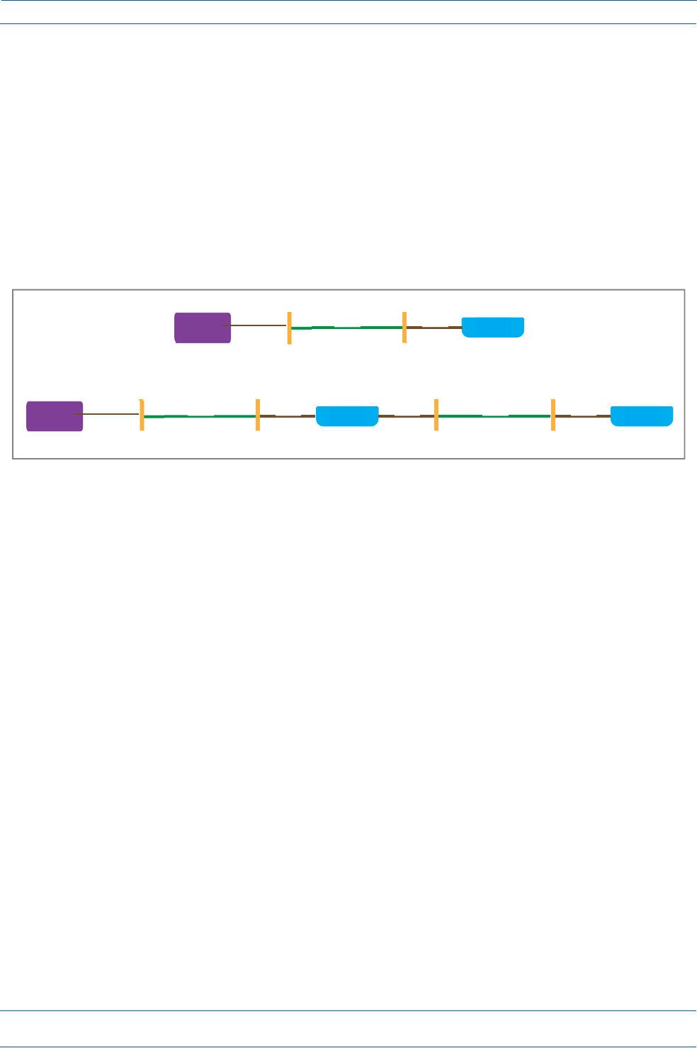
•
TherecanneverbemorethantwoRJ‐45connectionsinaCat6Acablerun,asdescribedbelowandas
showninFigure15.Minimizingtheseconnectionsimprovesthelinkmargin.
–
Inanon‐cascade,betweentheCATCardandtheAP,therecanbe
oneCat6APatchCordatthestartofaCat6Acablerun
asecondCat6APatchCordattheendofaCat6Acablerun.
–
Inacascade,betweenthePrimaryAPandtheSecondaryAP,therecanbe
oneCat6APatchCordatthestartofaCat6Acablerun
asecondCat6APatchCordattheendofaCat6Acablerun.
Figure15.MaximumNumberofRJ‐45ConnectionsinCableRuns
•
CommScopestronglyrecommendsusingfactoryterminatedandtestedCat6APatchCords.
CATCard
Cord
inCAN/TEN
RJ‐45
connection
Cat6A
Patch Cat6A
Cable
Cat6A
Patch
Cord
CAPL
RJ‐45
connection
CATCard
Cord
inCAN/TEN
RJ‐45
connection
Cat6A
PatchCat6A
Cable
Cat6A
Patch
Cord
CAPL
Cat6A
Patch
Cord
Cat6A
Cable
Cat6A
Patch
Cord
CAPL
RJ‐45RJ‐45RJ‐45
connectionconnectionconnection
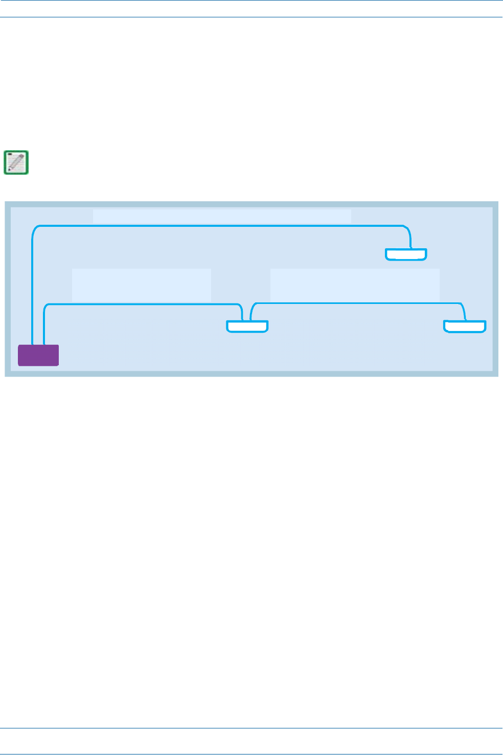
M0201AAB
©November2017CommScope,Inc.
ION®‐ESeriesLowPowerCarrierAccessPointInstallationGuide
Page41
InstallingCAPLs
•
ThemaximumCat6AcablelengthsforaninstallationwithCAPLswithaCopperInterfacearelistedbelow
(seeFigure16).
–
BetweenaCAPLandaportonanRJ45portonaCATCardintheCAN/TEN,themaximumCat6Acable
lengthis100meters,includingallCat6Acables,Cat6APatchCords,andPatchPanels.
–
ACat6APatchCordshouldnotexceed5meters.
–
ForcascadedCAPLs,themaximumCat6AcablelengthbetweentheAUXportonthePrimaryCAPL
andtheMAINportontheSecondary(cascaded)CAPL,includingthelengthoftheCat6APatchCord,
mustbelessthan100meters.
TheSecondaryCAPLmustgetitspowerthroughtheDCconnector(eitherfromalocalsupplyorhybrid
fiber);powerovertheCat6Acabletothecascadedunitisnotsupported.See"CascadeRules”onpage16.
Figure16.CAPLCat6ACableLengths
FromtheCAT/TENtotheCAPL,Cat6Acannotexceed100meters.
CAPL
CableRunA
fromtheCAT/TENtothePrimaryCAPL
Cat6Acannotexceed100meters
CableRunB
fromthePrimaryCAPLtotheSecondaryCAPL
Cat6Amustbelessthan100meters
CATCard
inCAN/TEN
CAPL
Primary
Note:ReferencestoCat6AisinclusiveofallCat6ACables,Cat6APatchCords,andPatchPanels
CAPL
Secondary
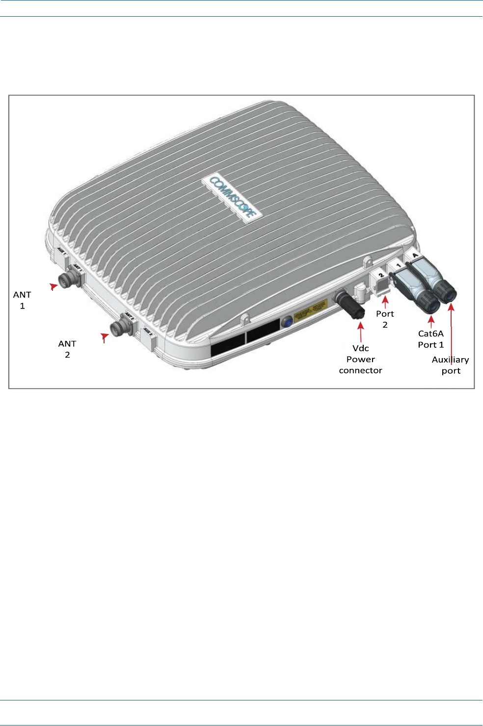
ION®‐ESeriesLowPowerCarrierAccessPointInstallationGuide
Page42
M0201AAB
©November2017CommScope,Inc.
InstallingCAPLs
CableaCAPLwithaCopperInterfaceandExternalDCPower
Figure17identifiestheconnectorsonaCAPLwithaCopperInterfacethatispoweredbyanexternalpower
source;correspondingcablesandconnectorsareshown.Fordetailsontheports,see"CAPLwithaCopper
InterfaceandExternalDCPower”onpage7.
Figure17.ConnectorsonaCAPLwithaCopperInterfacewithExternalDCPower
DothefollowingtoinstallaCAPLwithaCopperInterfacethatispoweredbyanexternalpowersource.
1
Obtainthefollowingcomponents,asrequiredforthisinstallation.
•
50
coaxialcablethatisofsufficientlengthtoreachfromtheCAPLtothepassiveantenna.Theend
ofthe50
coaxialcablethatwillconnecttotheANTconnectorcanbeeitherapush‐pullconnectorora
threadedconnector.
•
Followingtherulesin"Cat6ACableRequirementsforCAPLswithaCopperInterface”onpage39,
obtainCat6AcablethatisofsufficientlengthtoreachfromtheCAPLtotheION‐ECAN/TEN.
•
AllinstallationsrequireoneEthernetOCTISKit(PN7760652RJ‐45).AdditionalEthernetOCTISKits
arerequired(oneeach)forcascadingaSecondaryCAPLand/orconnectinganexternalEthernet
devicesuchasWiFioranIPcamera.
•
IfconnectingtoanexternalEthernetdevicesuchasWiFioranIPcamera,obtaintheappropriateCAT
cablefortheprotocoltowhichtheCAPLwillconnect.Thismodelsupportsa1000BASE‐Tand
802.3atClass4PoweroverCat6AEthernetconnection.
–
AsingleCAPLcansupportoneauxiliaryEthernetdevice.
–
AcascadedCAPLpaircansupportoneauxiliarydevice.
–
Followtherulesin"Cat6ACableRequirementsforCAPLswithaCopperInterface”onpage39,all
Cat6Acablerequirementsandcable‐lengthrulesbetweenaPrimaryandSecondaryCAPLalso
applytoconnectinganexternalEthernetdevice.
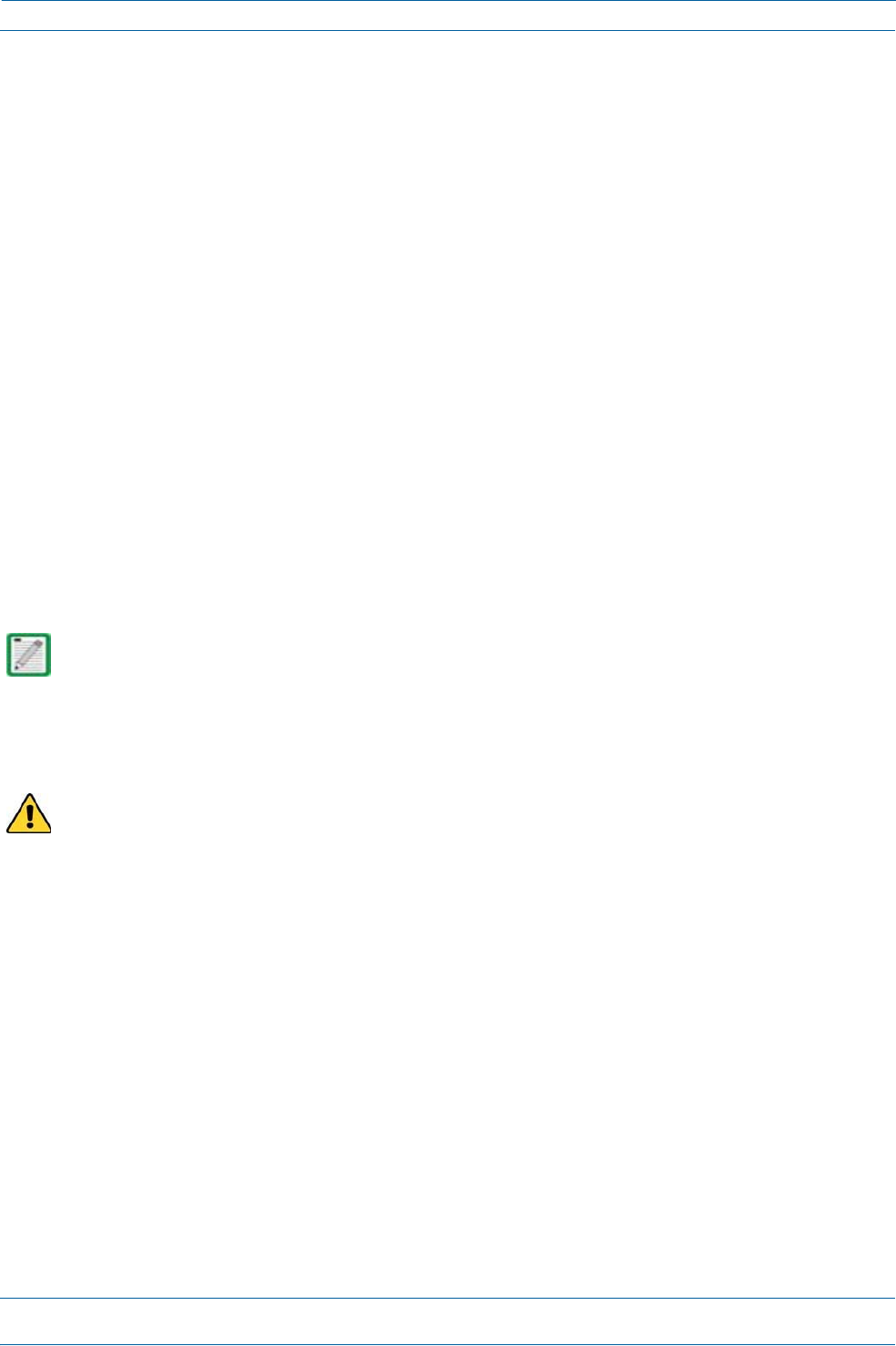
M0201AAB
©November2017CommScope,Inc.
ION®‐ESeriesLowPowerCarrierAccessPointInstallationGuide
Page43
InstallingCAPLs
2
ConnecttheCAPLANT1and/orANT2connectortoapassiveRFantenna.
a
Installthepassiveantennasperthemanufacturer’sinstallationinstructions.IfconnectingbothANT
connectors,youwillconnecttheCAPLtoeithertwoseparateexternalpassiveantennasortotwo
portsonacross‐polarizeddualantenna.EachconnectorsupportstwoRFbands(seeTable1on
page1).
b
Removetheplastic‐protectivecapfromthe4.3‐10connectors.
c
RemovetheIP67/EMIblankplugfromANT1/2connector.
d
Connectthepassivemulti‐bandantennatotheANT1orANT2connectorusingcoaxialcablewiththe
leastamountoflosspossible.
•
Ifthe50 coaxialcablehasapush‐pullconnector,makesurethecableisseatedfirmlyintheANT
1orANT2connector.
•
Ifthe50 coaxialcablehasathreadedconnector,torquetheconnector5N‐m(3.69ft‐lb).Donot
over‐tightentheconnector.
e
Connecttheotherendofthe50 coaxialcabletothepassiveantennainstalledinStepa.
3
Ifnecessary,repeatStep2toconnecta50 coaxialcabletotheotherANTconnector.
4
ConnecttheCAPLPort1connectorasappropriateforthisinstallation.
a
RemovethedustcapfromthePort1connector.
b
InstalltheEthernetOCTISKitontheendofthecablethatwillconnecttotheCAPL.(Refertothe
technicaldatasheetthatshipswiththeOCTISKitforfurtherinformation.)
c
ConnectoneendoftheCat6AcabletothePort1connectorandtheotherendtoanavailableporton
aCATCardintheCAN/TEN.
Port2ispluggedasitisnotusedinthisconfiguration.
5
(Optional)PortA(Auxiliaryport)providesacascadeconnectiontoanoptionallocallypoweredcascaded
CAPL,orprovidesaconnectiontoexternalEthernetdevicessuchasWiFiandIPcameras.CablePortAas
appropriateforthisinstallation.
PortAmustbepluggedifnotinuse.
a
RaisetheleverontheEMI/IP67caponPortAandremovethecap.
b
InstalltheEthernetOCTISKitontheendofthecablethatwillconnecttotheCAPL,andthenconnect
thatendofthecabletoCAPLPortA.(RefertothetechnicaldatasheetthatshipswiththeOCTISKit
forfurtherinformation.)
c
ConnecttheotherendoftheCATcabletotheEthernetportoftheauxiliarydevice.
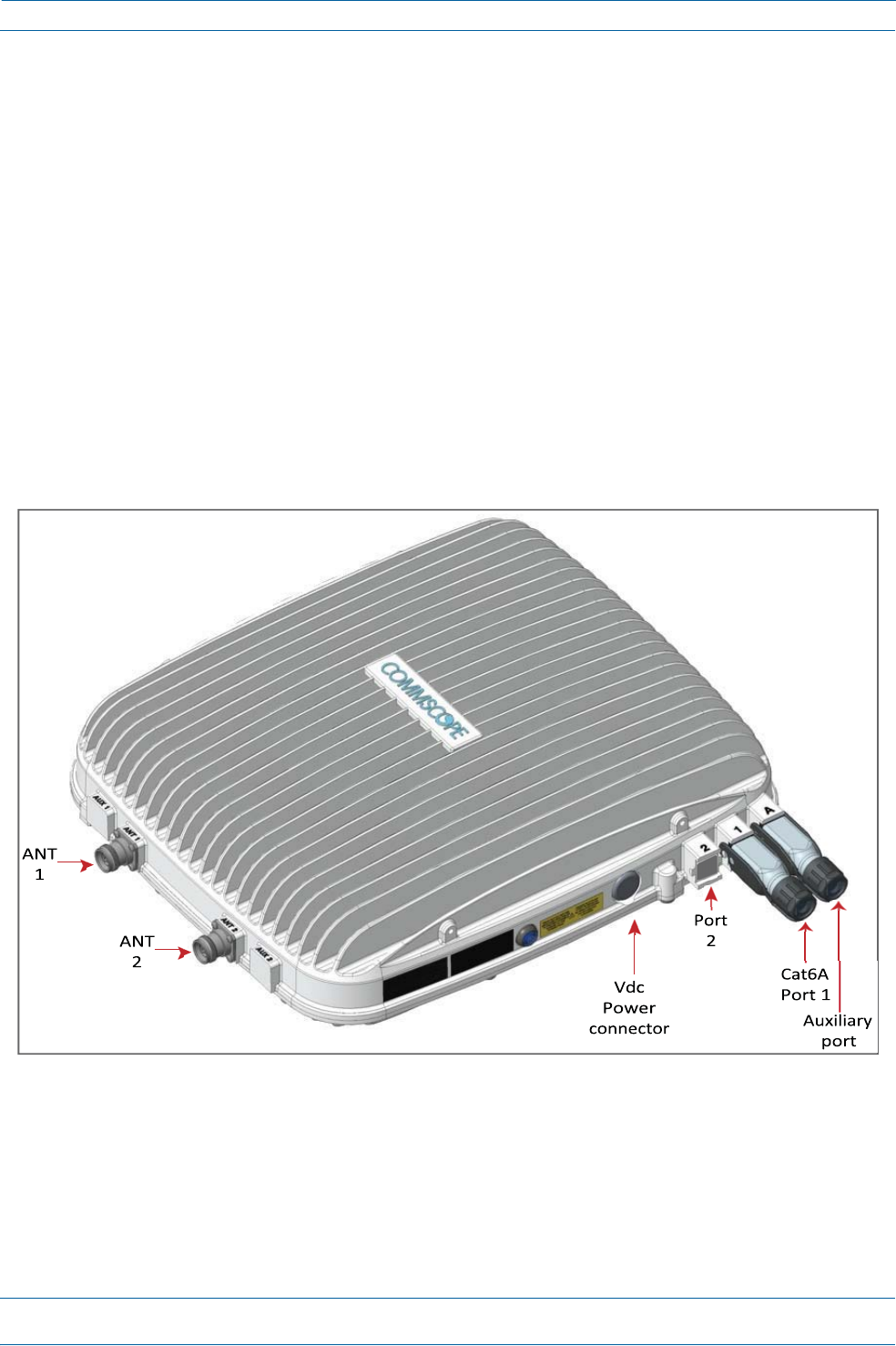
ION®‐ESeriesLowPowerCarrierAccessPointInstallationGuide
Page44
M0201AAB
©November2017CommScope,Inc.
InstallingCAPLs
6
ConnecttheVdcPowerconnectorasappropriateforthisinstallation.
•
ForaCAPLwithnolocalpowersupplyandnohybridfibercable,connectapowercable(notsupplied
byCommScope)totheproprietary4‐pin,36to60VdcPowerconnectorontheCAPL.
•
ForaCAPLpoweredbytheCAPLHybridFiberSpliceBoxKit(PN7774354‐xx),connectthe:
–
powercabletotheproprietary4‐pin,36to60VdcPowerconnectorontheCAPL,andterminate
theotherendintheHybridFiberSpliceBox
–
LCFiberJumpertothesuppliedOCTISconnector,andsplicetheotherendofthefiberjumpers
insidethelocally‐mountedCAPLHybridFiberSpliceBox.
•
ForaCAPLwiththeoptionalAC/DCPowerSupplyKit(PN7775087‐xx),connectitsLocalPower
JumperCableAssemblytotheproprietary4‐pin,36to60VdcPowerconnectorontheCAPL.
TheCAPLispoweredonassoonasyouconnecttheLocalPowerJumperCableAssemblytoapower
source;see"PoweringaCAPLandPowerLEDBehavior”onpage9.
CableaCAPLwithaCopperInterfaceandPoweroverCat6ACable
Figure18identifiestheconnectorsonaCAPLwithCopperInterface;correspondingcablesandconnectors
areshown.Fordetailsontheports,see"CAPLwithaCopperInterfaceandPowerCat6ACable”onpage8.
Figure18.ConnectorsonaCAPLwithaCopperInterface

M0201AAB
©November2017CommScope,Inc.
ION®‐ESeriesLowPowerCarrierAccessPointInstallationGuide
Page45
InstallingCAPLs
DothefollowingtoinstallaCAPLwithaCopperInterfacethatispoweredoveraCat6Acable.
1
Obtainthefollowingcomponents,asrequiredforthisinstallation.
•
50 coaxialcablethatisofsufficientlengthtoreachfromtheCAPLtothepassiveantenna.Theend
ofthe50 coaxialcablethatwillconnecttotheANTconnectorcanbeeitherapush‐pullconnectorora
threadedconnector.
•
Followingtherulesin"Cat6ACableRequirementsforCAPLswithaCopperInterface”onpage39,
obtainCat6AcablethatisofsufficientlengthtoreachfromtheCAPLtotheION‐ECAN/TEN.
•
AllinstallationsrequireoneEthernetOCTISKit(PN7760652RJ‐45).AdditionalEthernetOCTISKits
arerequired(oneeach)forcascadingaSecondaryCAPLand/orconnectinganexternalEthernet
devicesuchasWiFioranIPcamera.
•
IfconnectingtoanexternalEthernetdevicesuchasWiFioranIPcamera,obtaintheappropriateCAT
cablefortheprotocoltowhichtheCAPLwillconnect.Thismodelsupportsa1000BASE‐Tand
802.3atClass4PoweroverCat6AEthernetconnection.
–
AsingleCAPLcansupportoneauxiliaryEthernetdevice.
–
AcascadedCAPLpaircansupportoneauxiliarydevice.
–
Followtherulesin"Cat6ACableRequirementsforCAPLswithaCopperInterface”onpage39,all
Cat6Acablerequirementsandcable‐lengthrulesbetweenaPrimaryandSecondaryCAPLalso
applytoconnectinganexternalEthernetdevice.
2
ConnecttheCAPLANT1and/orANT2connectortoapassiveRFantenna.
a
Installthepassiveantennasperthemanufacturer’sinstallationinstructions.IfconnectingbothANT
connectors,youwillconnecttheCAPLtoeithertwoseparateexternalpassiveantennasortotwo
portsonacross‐polarizeddualantenna.EachconnectorsupportstwoRFbands(seeTable1on
page1).
b
Removetheplastic‐protectivecapfromthe4.3‐10connectors.
c
RemovetheIP67/EMIblankplugfromANT1/2.
d
Connectthepassivemulti‐bandantennatotheANT1orANT2connectorusingcoaxialcablewiththe
leastamountoflosspossible.
•
Ifthe50 coaxialcablehasapush‐pullconnector,makesurethecableisseatedfirmlyintheANT
1orANT2connector.
•
Ifthe50 coaxialcablehasathreadedconnector,torquetheconnector5N‐m(3.69ft‐lb).Donot
over‐tightentheconnector.
e
Connecttheotherendofthe50 coaxialcabletothepassiveantennainstalledinaonpage45.
3
Ifnecessary,repeat2onpage45toconnecta50 coaxialcabletotheotherANTconnector.
ThePowerconnectorandthePort2connectorarepluggedastheyarenotusedinthisconfiguration.

ION®‐ESeriesLowPowerCarrierAccessPointInstallationGuide
Page46
M0201AAB
©November2017CommScope,Inc.
InstallingCAPLs
4
ConnecttheCAPLPort1connectorasappropriateforthisinstallation.
a
Followingtherulesin"Cat6ACableRequirementsforCAPLswithaCopperInterface”onpage39,
obtainCat6AcablethatisofsufficientlengthtoreachfromtheCAPLtotheION‐ECAN/TEN.
b
RemovethedustcapfromthePort1connector.
c
FollowthelocalcleaningtechniquetocleanPort1.
d
InstallanEthernetOCTISKittoanendoftheCat6Acable,andthenconnectthatendofthecableto
CAPLPort1connector.(RefertothetechnicaldatasheetthatshipswiththeOCTISKitforfurther
information.)
e
ConnecttheotherendtheCat6AcabletoanavailableportonaCATCardintheCAN/TEN.
Port2ispluggedasitisnotusedinthisconfiguration.
5
(Optional)PortA(Auxiliaryport)providesacascadeconnectiontoanoptionallocallypowered
SecondaryCAPL,orprovidesaconnectiontoexternalEthernetdevicessuchasWiFiandIPcameras.
CablePortAasappropriateforthisinstallation.
PortAmustbepluggedifnotinuse.
a
RaisetheleverontheEMI/IP67caponPortAandremovethecap.
b
InstallanEthernetOCTISKittontheendofthecablethatwillconnecttotheCAPL,andthenconnect
thatendofthecabletoCAPLPortA.(RefertothetechnicaldatasheetthatshipswiththeOCTISKit
forfurtherinformation.)
c
ConnecttheotherendofthecabletotheEthernetportoftheauxiliarydevice.
6
ConnecttheVdcPowerconnectorasappropriateforthisinstallation.
•
ForaCAPLwithnolocalpowersupplyandnohybridfibercable,connectapowercable(notsupplied
byCommScope)totheproprietary4‐pin,36to60VdcPowerconnectorontheCAPL.
•
ForaCAPLpoweredbytheCAPLHybridFiberSpliceBox(PN7774354‐xx),connectthepowercable
theproprietary4‐pin,36to60VdcPowerconnectorontheCAPL,andterminatetheotherendinthe
HybridFiberSpliceBox.ConnecttheLCFiberJumpertosuppliedOCTISconnector,andsplicethe
otherendofthefiberjumpersinsidethelocally‐mountedHybridFiberSpliceBox.
•
ForaCAPLwiththeoptionalAC/DCPowerSupplyKit(PN7775087‐xx),connectitsLocalPower
JumperCableAssemblytotheproprietary4‐pin,36to60VdcPowerconnectorontheCAPL.
TheCAPLispoweredonassoonasyouconnecttheLocalPowerJumperCableAssemblytoapower
source;see"PoweringaCAPLandPowerLEDBehavior”onpage9.
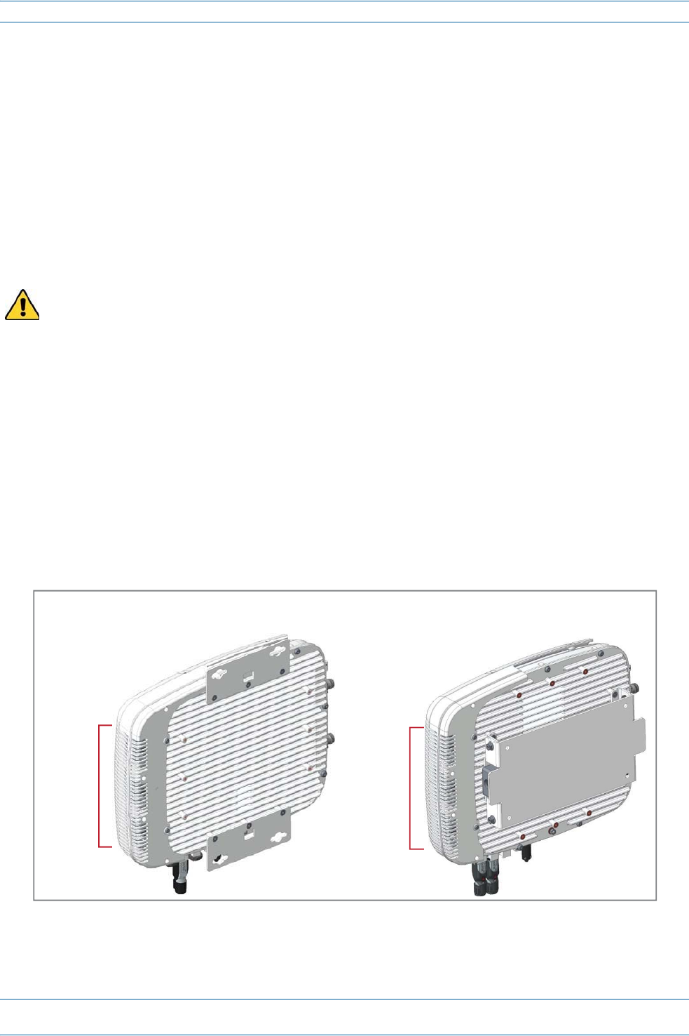
M0201AAB
©November2017CommScope,Inc.
ION®‐ESeriesLowPowerCarrierAccessPointInstallationGuide
Page47
CAPLM
AINTENANCE
CAPLMaintenance
ThefollowingsectionstellyouhowtoremoveaCAPLfrommountingbrackets,andprovidespreventative
maintenanceinstructions.
RemoveaCAPLfromaWallorCeilingMount
ShouldyouneedtoremovetheCAPLfromawallorceilingmount,dothefollowing.
1
PresstheCAPLPowerpushbuttontoplacetheCAPLintoalow‐powersleepstate,whichallowsyouto
safelyunplugtheCAPLwithoutapowerarc.
AlwayspressthePowerbuttontopowerofftheCAPLpriortodisconnectingitsPowercable.
2
MakesurethebluePowerLEDisoff.
3
UnplugtheCAPLcables.
4
Ifagroundwireisinstalled,loosenthegroundingscrewandremovethegroundwire.
5
ReversetheinstallationstepsthatcorrespondtohowthisCAPLismounted.
PreventativeCAPLMaintenanceforCAPLswiththeFanKitOption
TheCAPLdoesnotrequireextensivepreventativemaintenancemeasures.However,checkingthe
cleanlinessofaCAPLthathastheFanKitoptionatregularly‐scheduledintervalsisrecommended,
particularlytheenclosurevents,whichhelpsmaintainthelongevityofthefansandheatsinks.Figure19
showstwodifferentCAPLconfigurationstohelpyoufindtheenclosurevents.
Figure19.ExamplesofCAPLFanVentLocations
BottomofCAPLwith
FlatMountingBracket
BottomofCAPLwith
240WAC/DCPowerSupplyKit
Enclosure
vents
Enclosure
vents

ION®‐ESeriesLowPowerCarrierAccessPointInstallationGuide
Page48
M0201AAB
©November2017CommScope,Inc.
CAPLSpecifications
CAPLSPECIFICATIONS
Inadditiontotheinformationprovidedhere,otherspecificationscanbefoundinthefollowingsections:
•
WeightandDimensions—referto"DeterminetheCAPLMountingSite”onpage17
•
PowerConsumption—referto"DeterminethePowerConsumptionoftheCAPL”onpage17.
CAPLOutputSpecifications
Table‐1.
Ratedmeanoutputpowerperband<1GHz
Lapuissancemoyennedesortieparbande>608MHz
+18dBm
Ratedmeanoutputpowerperband>1GHz(noteexceptionbelow)
Puissancedesortiemoyenneévaluéeparbande>1GHz(noted'exceptionci‐dessous)
+21dBm
Ratedmeanoutputpowerinband2350‐2360MHz
Puissancedesortiemoyennenominaledanslabande2350‐2360MHz
+20dBm
Input/OutputImpedance
Lesimpédancesd'entréeetdesortie,et
50Ohms
TheManufacturer'sratedoutputpowerforthisequipmentisthecompositepowerinaband.Forsituations
whenmultiplecarriersignalsarepresent,thepowerpercarrierisreduced.Forexample,twocarriersina
bandwilleachhave3dBlesspowerthanasinglecarrierinaband.Thisisimportantwheretheoutputsignal
isradiatedandcancauseinterferencetoadjacentbandusers.Thispowerreductionistobebymeansofgain
reductionandnotbyanattenuatorattheoutputofthedevice.
Lapuissancedesortienominaledufabricantpourcetéquipementestlapuissancecompositedansune
bande.Pourlessituationsoùplusieursporteusessontprésentes,lapuissanceparporteuseestréduite.Par
exemple,deuxporteusesd'unebandeaurontchacun3dBdepuissanceinfér i e u r e àcelled'uneseuleporteuse
dansunebande.Ceciestimportantlorsquelesignaldesortieestrayonnéetpeutcauserdesinterférences
auxutilisateursdebandesadjacentes.Cetteréductiondepuissancedoitêt r e r éalis ée p a r réductiondegainet
nonparunatténuateurensortiedudispositif.
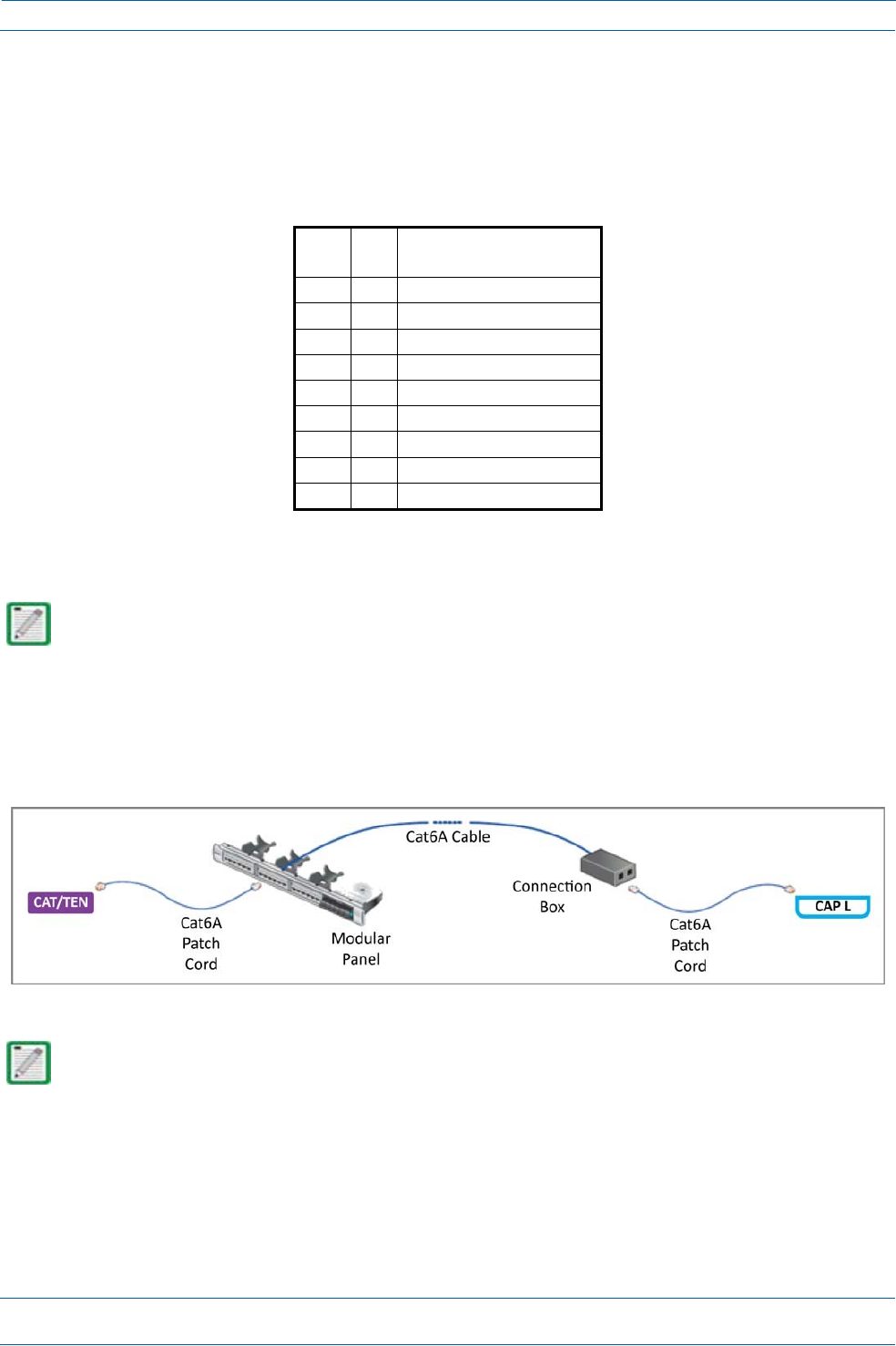
M0201AAB
©November2017CommScope,Inc.
ION®‐ESeriesLowPowerCarrierAccessPointInstallationGuide
Page49
CAPLSpecifications
CAPLBandwidthSpecifications
ION‐Esupportsavarietyofbandsinthe380to2700MHzrange.Thefrequenciesandbandwidthslistedin
thefollowingtable,forexample,representthenominalbandwidthspecificationsforCanadaintheNorth
Americaregion.
Table‐2.
MHzMHzNominalbandwidth(MHz)
Lalargeurdebandenominale
72874618
74675610
7687768
85186918
86989425
19301995 65
21102180 70
23502360 10
26202690 70
Cat6ASpecificationsandTestingRequirements
Thefollowingspecificationsareinadditiontothoselistedin"Cat6ACableRequirementsforCAPLswitha
CopperInterface”onpage39.
Cat6Aconnectionsmustbetestedwithadevicethatcanmeasurethecableparametersagainstthethresholds
definedinANSI/TIAstandards(suchastheFlukeDTX‐1800andDSX‐5000).Figure20showstheend‐to‐end
channelfromtheCAN/TENtotheCAPL,whichisinclusiveoftheCat6Acable,theCat6APatchCord,andthe
Panelandconnectionbox.Theend‐to‐endchannelmustmeettheCat6AU/UTPperformancedefinedbythe
TIA/EIA568C.2standard;seeTable1onpage50.
Figure20.ION‐EEnd‐to‐EndChannel
Somecableslisttheirperformancein“typical”performancevalues.However,sweep‐testingisnecessary
toconfirmactualperformance.CommScopestronglyrecommendsusingCat6Acablethathasbeentested
tothelistedfrequencywithtestconfirmationavailableforinspection.
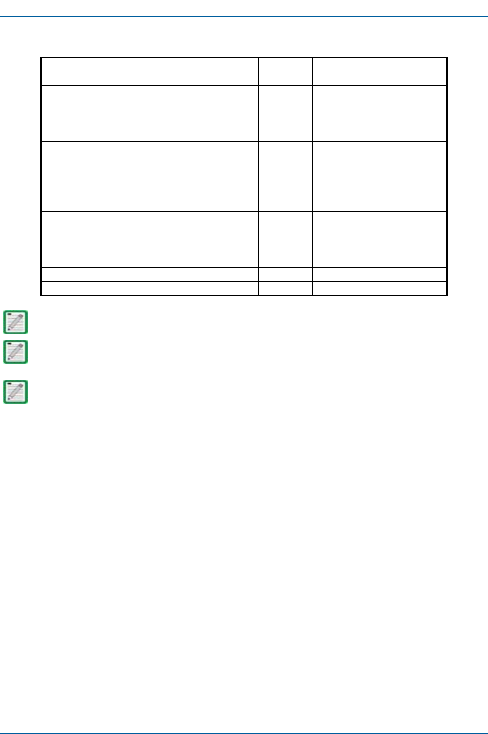
ION®‐ESeriesLowPowerCarrierAccessPointInstallationGuide
Page50
M0201AAB
©November2017CommScope,Inc.
CAPLSpecifications
Table1.Cat6AU/UTPPerformanceStandards(TIA/EIA568C.2)
MHzInsertionLoss(dB)
Channel/Link
NEXT(dB)
Channel/Link
PSumNEXT(dB)
Channel/Link
ACRF(dB)
Channel/Link
PSumACRF(dB)
Channel/Link
ReturnLoss
(dB)Channel/Link
12.3/1.965.0/65.062.0/62.0 63.3/64.2 60.3/61.2 19.0/19.1
44.2/3.563.0/64.160.5/61.851.2/52.148.2/49.119.0/21.0
85.8/5.058.2/59.455.6/57.045.2/46.142.2/43.119.0/21.0
106.5/5.556.6/57.854.0/55.543.3/44.240.3/41.219.0/21.0
168.2/7.053.2/54.650.6/52.239.2/40.136.2/37.118.0/20.0
209.2/7.851.6/53.149.0/50.737.2/38.234.2/35.217.5/19.5
2510.2/8.850.0/51.547.3/49.135.3/36.232.3/33.217.0/19.0
31.2511.5/9.848.4/50.045.7/47.533.4/34.330.4/31.316.5/18.5
62.516.4/14.143.4/45.140.6/42.727.3/28.324.3/25.314.0/16.0
10020.9/18.039.9/41.837.1/39.323.3/24.220.3/21.212.0/14.0
20030.1/26.134.8/36.931.9/34.317.2/18.214.2/15.29.0/11.0
25033.9/29.533.1/35.330.2/32.715.3/16.212.3/13.28.0/10.0
30037.4/32.731.7/34.028.8/31.413.7/14.610.7/11.67.2/9.2
40043.7/38.528.7/29.925.8/27.111.2/12.18.2/9.16.0/8.0
50049.3/43.826.1/26.723.2/23.89.3/10.26.3/7.26.0/8.0
PropagationDelayis555nanosecondsforchannel/498nanosecondsforlinktestedat10MHz.
DelaySkewis50nanosecondsforchannel/44nanosecondsforlinktestedat10MHz.
Foradditionalinformation,seealsoCommScopeProductSpecificationsfortheGigaSPEEDX10D®2091B
ETLVerifiedCategory6AU/UTPCable(760107201|2091BBL4/23W1000).(Clickhereaccessthe
documentonline.)
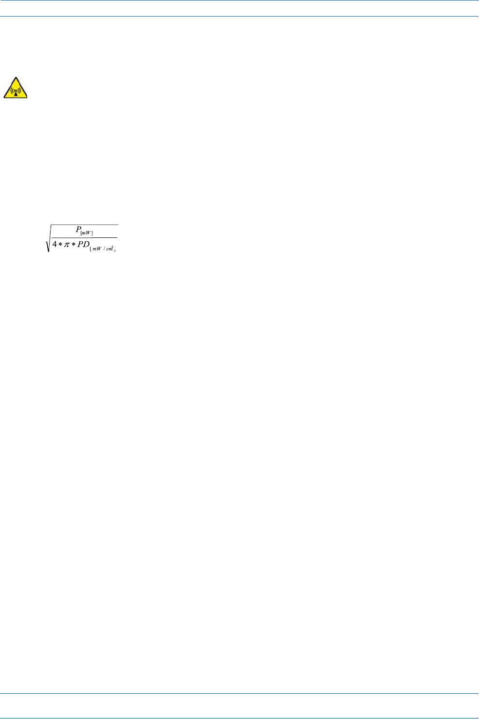
M0201AAB
©November2017CommScope,Inc.
ION®‐ESeriesLowPowerCarrierAccessPointInstallationGuide
Page51
ComplianceandStandardsCertification
C
OMPLIANCEAND
S
TANDARDS
C
ERTIFICATION
ThisisclassAequipment.Thisequipmentcancauseradiointerferenceindomesticareas.Inthiscasethe
operatorcanbeaskedtostartpreventiveaction.
FCCRFExposureRequirements
Forinstallations,whichhavetocomplywithFCCRFexposurerequirements,theantennaselectionand
installationmustbecompletedinawaytoensurecompliancewiththoseFCCrequirements.Dependingon
theRFfrequency,ratedoutputpower,antennagain,andthelossbetweentherepeaterandantenna,the
minimumdistanceDtobemaintainedbetweentheantennalocationandhumanbeingsiscalculated
accordingtothisformula:
D
[
cm
]
where
•
P(mW)istheradiatedpowerattheantenna,i.e.themax.ratedrepeateroutputpowerinadditiontothe
antennagainminusthelossbetweentherepeaterandtheantenna.
•
PD(mW/cm²)istheallowedPowerDensitylimitacc.to47CFR1.1310(B)forgeneralpopulation/
uncontrolledexposureswhichis
–
f(MHz)/1500forfrequenciesfrom300MHzto1500MHz
–
1forfrequenciesfrom1500MHzto100,000MHz
RFexposurecompliancemayneedtobeaddressedatthetimeoflicensing,asrequiredbytheresponsibleFCC
Bureau(s),includingantennaco‐locationrequirementsof1.1307(b)(3).
EMCStandards
•
ForinstallationsthathavetocomplywithEuropeanEN50385exposurecompliancerequirements,the
followingPowerDensitylimits/guidelines(W/m²)accordingtoICNIRParevalid:
–
2forfrequenciesfrom10MHzto400MHz
–
f(MHz)/200forfrequenciesfrom400MHzto2GHz
–
10forfrequenciesfrom2GHzto300GHz
•
ThisunitcomplieswithEuropeanstandardEN60950.

ION®‐ESeriesLowPowerCarrierAccessPointInstallationGuide
Page52
M0201AAB
©November2017CommScope,Inc.
ComplianceandStandardsCertification
FCCandISEDStandards
Notice:ForinstallationsthathavetocomplywithFCC/IndustryCanadarequirements:
English
ThisdevicecomplieswithFCCPart15.Operationissubjecttothefollowingtwoconditions:(1)thisdevice
maynotcauseinterference,and(2)thisdevicemustacceptanyinterference,includinginterferencethatmay
causeundesiredoperationofthedevice.
ThisdevicecomplieswithHealthCanada'sSafetyCode.TheinstallerofthisdeviceshouldensurethatRF
radiationisnotemittedinexcessoftheHealthCanada'srequirement.Informationcanbeobtainedat:
https://www.canada.ca/en/health‐canada/services/environmental‐workplace‐health/reports‐publications/
radiation/safety‐code‐6‐health‐canada‐radiofrequency‐exposure‐guidelines‐environmental‐workplace‐healt
h‐health‐canada.html
Changesormodificationsnotexpresslyapprovedbythepartyresponsibleforcompliancecouldvoidthe
user'sauthoritytooperatetheequipment.
Theantenna(s)usedforthistransmittermustbeinstalledtoprovideaseparationdistanceofatleast20cm
fromallpersonsandmustnotbeco‐locatedoroperatinginconjunctionwithanyotherantennaor
transmitter.
French
CetappareilestconformeàFCCPartie15.SonutilisationestsoumiseàLesdeuxconditionssuivantes:(1)cet
appareilnepeutpasprovoquerd’interférenceset(2)cetappareildoitaccepterTouteinterférence,ycompris
lesinterférencesquipeuventcauserunmauvaisfonctionnementdudispositif.
CetappareilestconformeavecSantéCanadaCodedesécurité6.Leprogrammed’installationdecetappareil
doits’assurerquelesrayonnementsRFn’estpasémisau‐delàdeI’exigencedeSantéCanada.Les
informationspeuventêtreobtenues:
https://www.canada.ca/en/health‐canada/services/environmental‐workplace‐health/reports‐publications/
radiation/safety‐code‐6‐health‐canada‐radiofrequency‐exposure‐guidelines‐environmental‐workplace‐healt
h‐health‐canada.html
Leschangementsoumodificationsnonexpressémentapprouvésparlapartieresponsabledelaconformité
pourraientannulerl'autoritédel'utilisateuràutilisercetéquipement.
Laoulesantennesutiliséesaveccetémetteurdoiventêtreinstalléesavecuneséparationd’auminimum
20cmavectoutepersonneetnedoiventpasêtreco‐localisée s o u ut il i séesavectouteautreantenneoutout
autree
́m e t t e u r .
ForaClassAdigitaldeviceorperipheral.
ThisequipmenthasbeentestedandfoundtocomplywiththelimitsforaClassAdigitaldevice,pursuantto
EN55022andPart15oftheFCCRules.Theselimitsaredesignedtoprovidereasonableprotectionagainst
harmfulinterferencewhentheequipmentisoperatedinacommercialenvironment.
Thisequipmentgenerates,uses,andcanradiateradiofrequencyenergyand,ifnotinstalledandusedin
accordancewiththeinstructionmanual,maycauseharmfulinterferencetoradiocommunications.Operation
ofthisequipmentinaresidentialareaislikelytocauseharmfulinterferenceinwhichcasetheuserwillbe
requiredtocorrecttheinterferenceathisownexpense.

M0201AAB
©November2017CommScope,Inc.
ION®‐ESeriesLowPowerCarrierAccessPointInstallationGuide
Page53
CONTACTINGCOMMSCOPE
ContactingCommScope
ThefollowingsectionstellyouhowtocontactCommScopeforadditionalinformationorforassistance.
DCCSGlobalTechnicalSupport
ThefollowingsectionstellyouhowtocontacttheCommScopeDistributedCoverageandCapacitySolutions
(DCCS)TechnicalSupportteam.Supportisavailable7daysaweek,24hoursaday.
TelephoneHelplines
UsethefollowingHelplinetelephonenumberstogetlivesupport,24hoursaday:
24x7+1888‐297‐6433(TollfreeforU.S.andCanada)
EMEA8:00‐17:00(UTC+1)+80073732837(TollfreeforpartsofEMEAandAustralia)
+49909969333(Tollchargeincurred)
CallstoanEMEAHelplineoutsideofthe8:00to17:00timeframewillbe
forwardedtothe24x7Helpline.
OnlineSupport
TogototheCommScopeDCCSSupportRequestwebsitefromwhichyoucaninitiateaTechnicalSupport
ticket,dooneofthefollowing:
•
ScantheQRCodetotheright.
•
IfviewingthisdocumentonlineasaPDF,clickonthefollowingURLlink:
http://www.commscope.com/wisupport
•
EntertheprecedingURLintoyourwebbrowser,andthenpressENTERonyourkeyboard.
WasteElectricalandElectronicEquipmentRecycling
CountryspecificinformationaboutcollectionandrecyclingarrangementspertheWasteElectricaland
ElectronicEquipment(WEEE)DirectiveandimplementingregulationsisavailableonCommScope’swebsite.
ToaccessinformationontheCommScoperecyclingprogram,doanyofthefollowing:
•
ScantheQRCodetotheright.
•
IfviewingthisdocumentonlineasaPDF,clickonthefollowingURLlink:
http://www.commscope.com/About‐Us/Corporate‐Responsibility‐and‐Sustainability/Environment/Rec
ycling/
•
EntertheprecedingURLintoyourwebbrowser,andthenpressENTERonyourkeyboard.

ION®‐ESeriesLowPowerCarrierAccessPointInstallationGuide
Page54
M0201AAB
©November2017CommScope,Inc.
ContactingCommScope
HardwaretoSoftwareMappingInformation
1
ScantheQRCodetotherighttoviewordownloadtheminimumsoftwarerequirementsfor
eachoftheDCCShardwaremodules.Alternatively,youcangotothefollowingwebaddressto
accesstheportal:
http://www.commscope.com/collateral/DCCS_HW_SW_Mapping/
2
Clickonadocumentlinktoopenit,orrightclickonthelinkandselecttheSavetargetas…optionfromthe
contextualmenu.
DCCSTechnicalTraining
1
ToaccesstrainingontheonlineCommScopeDASandSmallCellInstitute,dooneofthefollowing:
•
ScantheQRCodetotheright.
•
IfviewingthisdocumentonlineasaPDF,clickonthefollowingURLlink.
http://www.commscopetraining.com/courses/dassc/
•
EntertheprecedingURLintoyourwebbrowser,andthenpressENTERonyourkeyboard.
2
Reviewthecourseslistedinseparatecoursepanels;forfurtherinformationonacourse,clickitsFull
detailsbutton.Instructor‐ledcoursesareconductedinNorthAmericaandEurope.Beforechoosinga
course,pleaseverifytheregion.
3
Toviewthecoursescheduleandregister,clickCourseRegistrationatthetopofthecoursepage;this
opensthePartnerLearningCenterLoginpage.
•
Ifyouhaveanaccount,enteryourUsernameandPassword,andthenclickLogin.(ClickontheReset
Passwordlinkifyoudonothaveyourlogininformation.)
•
Ifyoudon'thaveanaccount,clickontheCreateNewUserAccountlinkundertheLoginbutton,and
followtheprompts.
Onceyouhaveloggedin,youwillseealistofavailableclassdates.
4
ClickthedateyoupreferandselecttheEnrollorRegisterNowbuttontoenroll.Followtheprompts
throughthepaymentprocess.
5
ClickeithertheAvailableTrainingorCalendartabtoviewothertrainingcourses.
Fortrainingrelatedquestions,pleasecontacttheCommScopeDASandSmallCellInstituteatoneofthe
followingemails,asappropriateforyourlocation:
Americas:DASTrainingUS@CommScope.com
EMEA:DASTrainingEMEA@CommScope.com

M0201AAB
©November2017CommScope,Inc.
ION®‐ESeriesLowPowerCarrierAccessPointInstallationGuide
Page55
ContactingCommScope
AccessingION‐ESeriesUserDocumentation
1
ScantheQRCodetotherighttogodirectlytotheCommScopeDCCSCustomerPortal,where
youcanaccesstheDCCSuserdocumentation.
Alternatively,youcangotothefollowingwebaddresstoaccesstheportal:
https://www.mycommscope.com
2
AccesstotheCustomerPortalrequiresauseraccountandpassword.OntheSignInpage,dooneofthe
following:
•
Ifyouhaveanaccount,enteryourEmailaddressandPassword,andthenclickSignIn.
•
Ifyoudon’thaveanaccount,clickNewuserregistration,andfollowtheprompts.
3
ClickDCCStoopenthesite.
4
Selectyoursite,andthenclickonaproductlinktoopentheproductpage.
5
Clickonthetitleofanydocumenttoopenit.

ION®‐ESeriesLowPowerCarrierAccessPointInstallationGuide
Page56
M0201AAB
©November2017CommScope,Inc.
ContactingCommScope
COMMSCC,PE®