Anoto Korea AP-701 DIGITAL PEN User Manual
Pen Generations, Inc. DIGITAL PEN
User Manual

Strictly Confidential
QUICK USER GUIDE for AP-701
(Summary version 1st)
This equipment should be installed and operated
with a minimum distance of 20 centimeters
All black & Black body & Blue Pen Cap
with
a
minimum
distance
of
20
centimeters
between the radiator and your body
1. AP-701, SPEC.-1/2
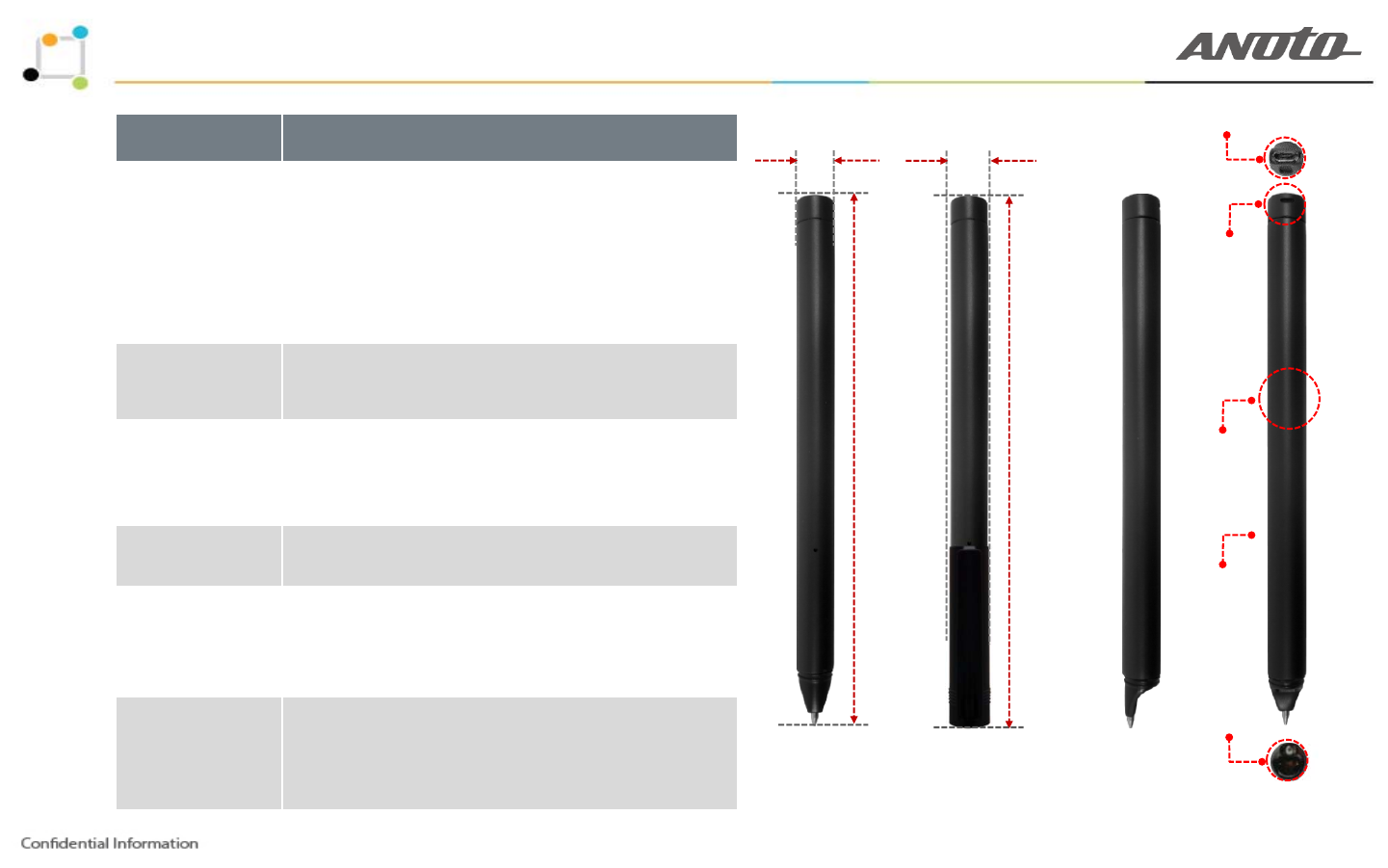
USB Connector (No Rubber Cap)
Criteria Descriptions
Appearance
- Dimensions : ① 152.9mm (with Pen Cap)
- Dimensions : ② 150.4mm (without Pen Cap)
- Dimensions : ③ 10.5mm .(Pen Body)
③ 10.5mm ④ 13.4mm
Lanyard Hole
Appearance
(Size & Weight) - Dimensions : ④ 12.6mm .(Pen Cap)
- Weight : 18g
- MMI : Green / Blue / Red LED Lamp / Buzzer Sound
Lanyard
Hole
Communication - Bluetooth Dual Mode 4.2 (Bluetooth classic & BLE)
Writing mode
(PG & APE)
- Operating angle : -45˚ to 50˚
- Reliable streaming with buffering
Llt t i
② 150.4mm ① 152mm Cylinder type
(Pen Body)
-
L
ow
l
a
t
ency s
t
ream
i
ng
Internal Storage - 4MB (On board type)
Buzzer & LED
Hole
Operation time - About 10 hours in continuous writing
- About 10 days in waiting mode
-
Lanyard(Necklace type) : Pen cap & Pen body
Refill Tip
&
Sensor
2 of 5
Etc-01
Lanyard(Necklace
type)
:
Pen
cap
&
Pen
body
- No power button
[ Front view ] [ Right side view ] [ Rear view ]
1. AP-701, SPEC.-2/2
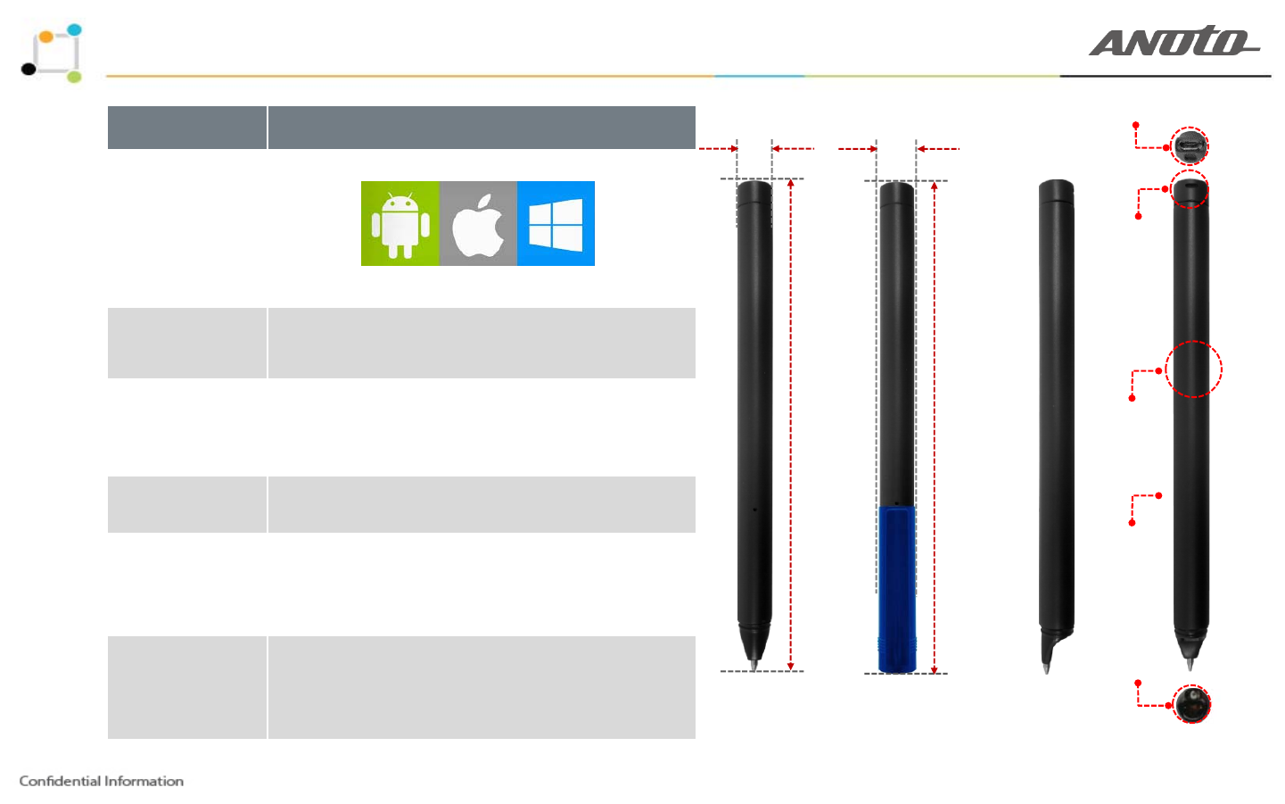
USB Connector (No Rubber Cap)
Criteria Descriptions
Platform
③ 10.5mm
Lanyard Hole
④ 13.4mm
Support(SDK)
Android / iOS / Windows
HW
-
Process
-
Cortex
M4 208Mhz
Lanyard
Hole
HW
-
Process
-
Cortex
M4
208Mhz
Writing mode
- Operating angle : -45˚ to 50˚
- Reliable streaming with buffering
-
Low latency streaming
② 150.4mm Cylinder type
(Pen Body)
① 152mm
Low
latency
streaming
Internal Storage - 4MB (On board type)
Battery type
Buzzer & LED
Hole
Battery
type
(Capacity) - Lithium Polymer / 280 mA
Etc
02
- Full Charging : 1 Hour
Refill Tip
&
Sensor
2 of 5
Etc
-
02
- Slim Design
[ Front view ] [ Right side view ] [ Rear view ]
2. AP-701, Full PKG(Detail Components)
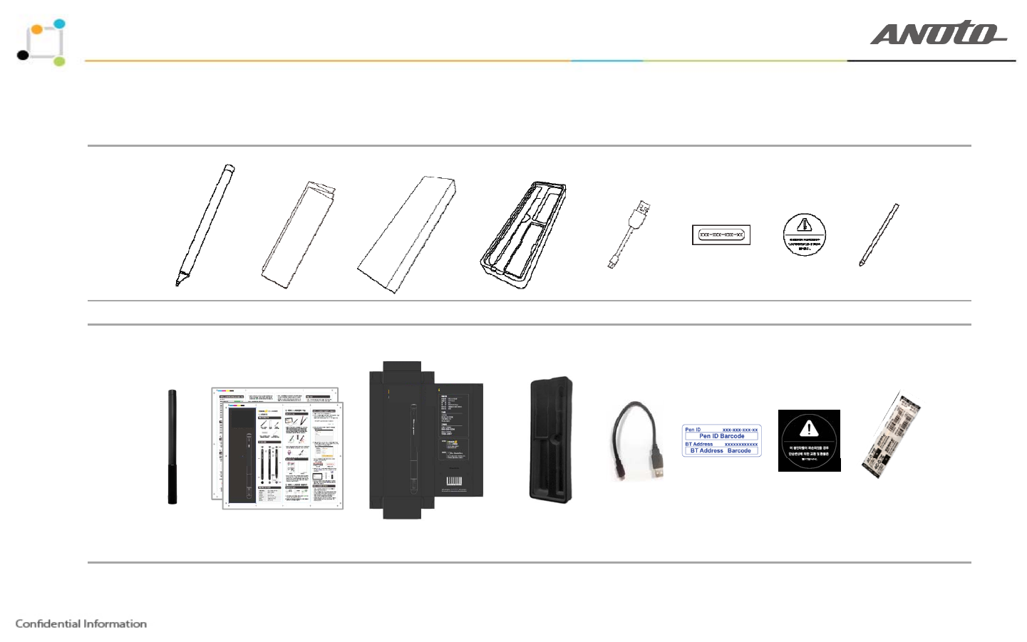
2-1. AP-701 : Full-PKG(included accessories)
Smart Pen User Manual Individual-PKG Inner case(tray) USB Charger cable Pen ID sticker Seal stickers Refill tip
2 of 5
[customer’s Sample guide]

3. AP-701, Key features(function)-1/3
3-1. AP-701 No power button.
3-2. AP-701 Always power on status.
3-3. AP-701 Remained battery is under 2%
or received the command to power off from the host device application(app.)
3-4. Power On/Off
- AP-701 is in power off, it is possible to turn AP-701 on by connecting to PC USB port or Charger USB port
It will take about 30 seconds to complete the booting
- AP-701 is in power on, it is able to turn AP-701 off by the command of host device application(app.)
When the remained battery is under 2%, AP-701 will turn off automatically.
It
will
take
about
30
seconds
to
complete
the
booting
2 of 5
3. AP-701, Key features(function)-2/3
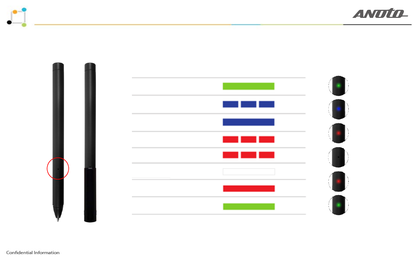
3-5. AP-701 supports 3-color LED and the buzzer sound for user notification
Power On
Searching
Steady
Blinking
Connected
Low battery
Steady
Blinking
Full memory
Off & Sleep
Blinking
Off
Charging
Full Charging
Stead
y
Steady
2 of 5
[ No Actual Size ] [ 3-LED Action ][ 3-LED Guide ]

3. AP-701, Key features(function)-3/3
3-6. AP-701 Usage(Lanyard lace)
2 of 5
4. AP-701, User manual(Connected & Pairing)-1/4
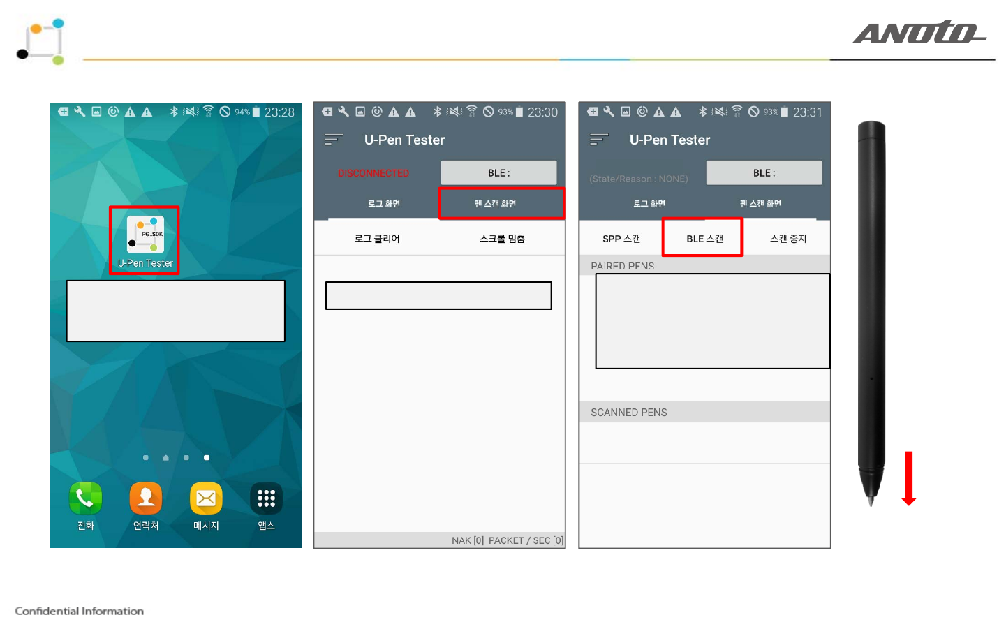
SCANNING
1. U-PEN Tester app icon
&
U-PEN Tester app loading
2. Select “Pen scanning” Button 3. Select “BLE Scan” button
&
Pen down (Click!)
&
W
a
i
t
in
g
f
e
w
seco
n
d
at g e seco d
Pen down (Click)
2 of 5
4. AP-701, User manual(Connected & Pairing)-2/4
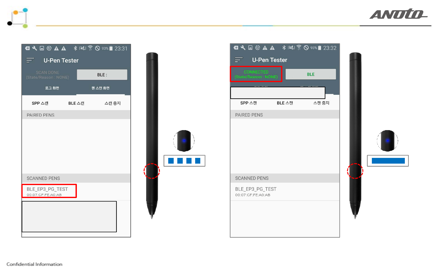
5. U-PEN Connected
MMI State :
The blue LED is turning on
and blinking
MMI State :
The blue LED is steadily
4. Scanning complete
&
Select “Pen ID”
2 of 5
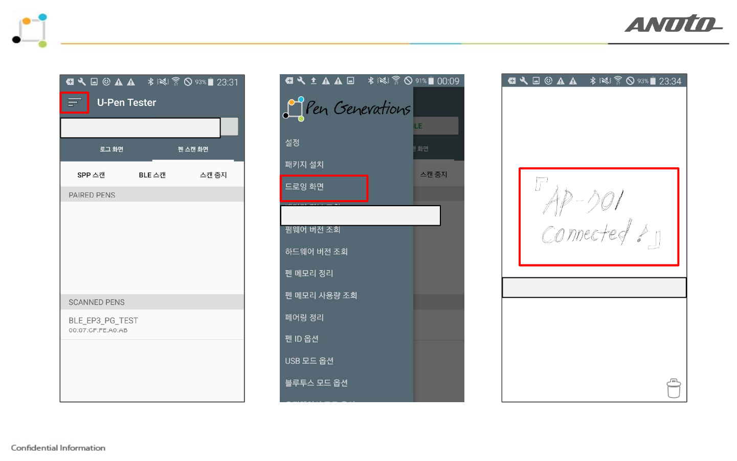
4. AP-701, User manual(Drawing mode)-3/4
1. Select “Menu” Icon
2. Select “Drawing Mode”
3. Writing “AP-701 Connected”
2 of 5
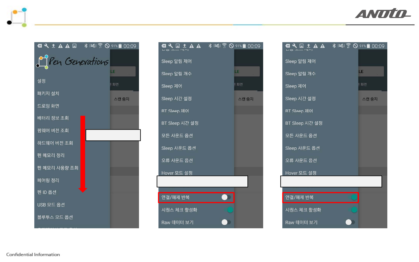
4. AP-701, User manual(Disconnected mode)-4/4
1. Scroll Down
2. AP-701 Connected mode 3. AP-701 Disconnected mode
2 of 5

4. AP-701, User manual
Warning : This device complies with part 15 of the FCC Rules. Operation is subject to the
following two conditions: (1)This device may not cause harmful interference, and (2) this device
must accept any interference
received Including
interference that may cause undesired operation
must
accept
any
interference
received
,
Including
interference
that
may
cause
undesired
operation
.
Note : This equipment has been tested and found to comply with the limits for a Class B digital
device, pursuantto part 15 of the FCC Rules. These limits are designed to provide reasonable
protection against harmful interference in a residential installation This equipment generates,
uses and can radiate radio frequency energy and, if not installed and used in accordance with
the instructions, may cause harmful interference to radio communications, However, there is no
guarantee that interference will not occur in a particular installation. If this equipment does
cause harmful interference to radio or television reception, which can be determined by turning
the equipment off and on the user is encouraged to try to correct
theinterference
by one or
the
equipment
off
and
on
,
the
user
is
encouraged
to
try
to
correct
theinterference
by
one
or
more of the following measures: -Reorient or relocate the receiving antenna. -Increase the
separation between the equipment and receiver. -Connect the equipment into an outlet on a
circuit different from that to which the receiver is connected. -Consult the dealer or an
ex
p
erienced radio/TV technician for hel
p
.
pp
***The grantee is not responsible for any changes or modifications not expressly approved by
the party responcible for compliance. Such modifications could void the user's authority to
operate the equipment.
12

Thank you for your attention