Appareo Systems 1535103 Agricultural Computing Device with Cellular/Satellite/WiFi/BT and M2M Transmitters User Manual
Appareo Systems, LLC Agricultural Computing Device with Cellular/Satellite/WiFi/BT and M2M Transmitters
Contents
- 1. User Manual
- 2. Manual
User Manual
This document and the information
contained herein are the property of
Appareo Systems, LLC and are
confidential. They may not be disseminated
or redistributed without the written
permission of Appareo Systems, LLC
APPAREO SYSTEMS, LLC
FARGO, NORTH DAKOTA 58102
Gateway Installation Manual
DOCUMENT NUMBER
600840-000038
Document Type
Manual
Last Revised
3/22/16
REV
1.2
Sheet
1 of 9
Gateway Installation Manual
GW03

Gateway Installation Manual
Rev: 1.2
Last Revised: 3/22/16
Document Number: 600840-000038
Page 2 of 9
Record of Revisions
Revision
Number
Change Description
Effective
Date
Inserted By
1.0
Initial Release
1/13/16
Lee Hinsz
1.1
Change “ 30 cm separation distance” to “40 cm” per
check from NCEE test lab
2/3/16
Lee Hinsz
1.2
Addition of “60 cm” for Canada per RSS-102. Addition of
section 3.4.4 Condition of operation section and
statement.
3/22/16
Lee Hinsz

Gateway Installation Manual
Rev: 1.2
Last Revised: 3/22/16
Document Number: 600840-000038
Page 3 of 9
Table of Contents
List of Figures ............................................................................................................................ 4
List of Tables ............................................................................................................................. 4
1. SYSTEM OVERVIEW .......................................................................................................... 5
2. PURPOSE ........................................................................................................................... 5
3. GENERAL INFORMATION .................................................................................................. 5
3.1. SPECIAL TOOLS REQUIRED ................................................................................. 5
3.2. INSTALLATION INSTRUCTIONS OVERVIEW ........................................................ 6
3.3. PARTS LIST FOR INSTALLATION .......................................................................... 6
3.4. HARDWARE COMPONENTS BACKGROUND ........................................................ 7
3.4.1. Electrical Characteristics ................................................................................... 7
3.4.2. Weight and Balance Information ........................................................................ 7
3.4.3. Equipment Dimensions ..................................................................................... 7
3.4.4. Conditions for operation .................................................................................... 7
4. CONFIGURATION ............................................................................................................... 8
4.1. Gateway System Separation Distances .................................................................... 8
4.2. Gateway System Separation Distance Illustration .................................................... 9

Gateway Installation Manual
Rev: 1.2
Last Revised: 3/22/16
Document Number: 600840-000038
Page 4 of 9
List of Figures
Figure 1 Separation Distance ..................................................................................................... 9
List of Tables
Table 1 System Component Minimum Spacing .......................................................................... 6
Table 2 Parts List for Installation ................................................................................................ 6
Table 3 Weight and Balance Information.................................................................................... 7
Table 4 Equipment Dimensions ................................................................................................. 7
Table 5 Separation Distance ...................................................................................................... 8

Installation Manual
Rev: 1.2
Last Revised: 3/22/16
Document Number: 600840-000038
Page 5 of 9
1. SYSTEM OVERVIEW
Gateway is an embedded computer that provides interfacing capability among a variety of wired
and wireless networks. It implements WAN designs, with the additions of Bluetooth, WIFI, 433-
MHz radio, and Satcom interfaces.
2. PURPOSE
This Installation Manual is intended to inform installers and users of the proper placement,
configuration and distances between system components.
3. GENERAL INFORMATION
3.1. SPECIAL TOOLS REQUIRED
In addition to SAE standard and/or metric wrenches, sockets, and screw drivers, the following
tool are required:
1) Torque Wrench (in-lbs)
2) Wrench set
Installation Manual
Rev: 1.2
Last Revised: 3/22/16
Document Number: 600840-000038
Page 6 of 9
3.2. INSTALLATION INSTRUCTIONS OVERVIEW
System installation is accomplished in the following steps:
1) Installation of Gateway into the tractor cab headliner
a. Torque the antenna terminations to Gateway RF SMA connectors with a torque
spec of 7-10 in-lbs +/- 0.5 in-lbs. Mount the Gateway enclosure to the cab with ¼”
or 6-mm fasteners and a torque of 30 in-lbs.
2) Installation of Antennas
a. Find a location on the equipment such that the following distances are the
minimum spacing between system components.
Table 1 System Component Minimum Spacing
Operator
Gateway
Antenna Hub 1
(Recommended minimum
spacing between antenna
hubs is 7.5 cm)
40 cm (USA)
60 cm (Canada)
20 cm
Antenna Hub 2
40 cm (USA)
60 cm (Canada)
20 cm
Gateway
20 cm
N/A
b. Ensure the antennas have a ground place of 300 x 300 mm around them.
c. Torque the antenna mounting nut (M14x1) to 30 +/- 0.5 in-lbs.
3.3. PARTS LIST FOR INSTALLATION
The following parts are required for the installation of Gateway.
Table 2 Parts List for Installation
Parts List for Installation
Item
Nomenclature
Part Number
QTY
1
Gateway
153510-000003
1
2
Antenna Hub 1
NA
1
3
Antenna Hub 2
NA
1
Installation Manual
Rev: 1.2
Last Revised: 3/22/16
Document Number: 600840-000038
Page 7 of 9
3.4. HARDWARE COMPONENTS BACKGROUND
3.4.1. Electrical Characteristics
Input Power Requirements: 9-16 VDC
Current Draw at 14VDC: 250mA (nominal)
3.4.2. Weight and Balance Information
The total weight of the Garrison and antenna is listed below.
Table 3 Weight and Balance Information
Component
Weight (oz)
Weight (lbs)
Gateway
70.544
4.409
Antenna Hub 1 (HCEL-S2-0164A-01 )
26.624
1.664
Antenna Hub 2 (HIRD-S2-0146A-01)
26.624
1.664
3.4.3. Equipment Dimensions
Equipment dimensions are outlined in the table below for all required components in Gateway.
All figures given are representative of maximum equipment dimensions (where applicable).
Table 4 Equipment Dimensions
Component
Length
(mm)
Width
(mm)
Height
(mm)
Gateway
165
159
54
Antenna Hub 1 (HCEL-S2-0164A-01 )
124.3
80.3
80.3
Antenna Hub 2 (HIRD-S2-0146A-01)
124.3
80.3
80.3
3.4.4. Conditions for FCC 15.231 (a-d) operation
IMPORTANT NOTICE!!!!
This device can be configured to transmit on the 433 MHz frequency following the requirements
of 47 CFR 15.231. Failure to adhere to this requirement void’s the authority to operate the
equipment!
The developer configuring Gateway’s control signal for the user application is responsible for
ensuring compliance to FCC 15.231(a-d).
In the event where the specific application in which the installed Gateway will be used, will not
ensure that a control signal will always be sent as the purpose of the transmission, then the
installer must set the Gateway to only operate in 15.231(e) mode (i.e., “periodic operation”).

Installation Manual
Rev: 1.2
Last Revised: 3/22/16
Document Number: 600840-000038
Page 8 of 9
To set the device to transmit in FCC Part 15.231(e) mode, use the API command string as
indicated below in quotes (“ ”).
“iLPD433.send(“MyMessage”,9,
FCC_PERIODIC_15_231_E,suggestedRetryIntervalMS,100,actualSentPowerDBM);”
Otherwise in the above command, replace the argument “FCC_PERIODIC_15_231_E” with
“FCC_APERIODIC_15_231_AD” for 15.231(a-d) mode with the appropriate control message
setup.
4. CONFIGURATION
With equipment installed, final configuration must meet the minimum separation distance in
Table 5 and Section 4.2.
4.1. GATEWAY SYSTEM SEPARATION DISTANCES
Operator
Gateway
Antenna Hub 1, 2
(Recommended minimum
spacing between antenna
hubs is 7.5 cm)
40 cm (USA)
60 cm (Canada)
20 cm
Gateway
20 cm
N/A
Table 5 Separation Distance
Installation Manual
Rev: 1.2
Last Revised: 3/22/16
Document Number: 600840-000038
Page 9 of 9
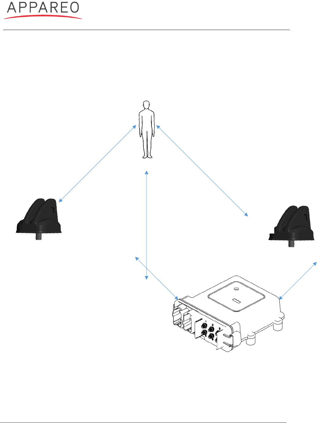
4.2. GATEWAY SYSTEM SEPARATION DISTANCE ILLUSTRATION
Gateway and the following components must follow the distances in the following illustration to
comply with FCC part 1.310.
Operator
Antenna Hub 1
Antenna Hub 2
Gateway
40 cm (USA)
60 cm (Canada)
20 cm
20 cm
20 cm
Figure 1 Separation Distance
40 cm (USA)
60 cm (Canada)