Applied Concepts 31XXXXXX Notebook With Wireless LAN Module Document ID
Averatec Inc., Notebook With Wireless LAN Module Document ID
UserManual.wiki
>
Applied Concepts
>
31XXXXXX User Manual
Users Manual
Navigation menu
Upload a User Manual
Namespaces
Wiki Guide
HTML
PDF
Info
Views
User Manual
Discussion / Help
Navigation
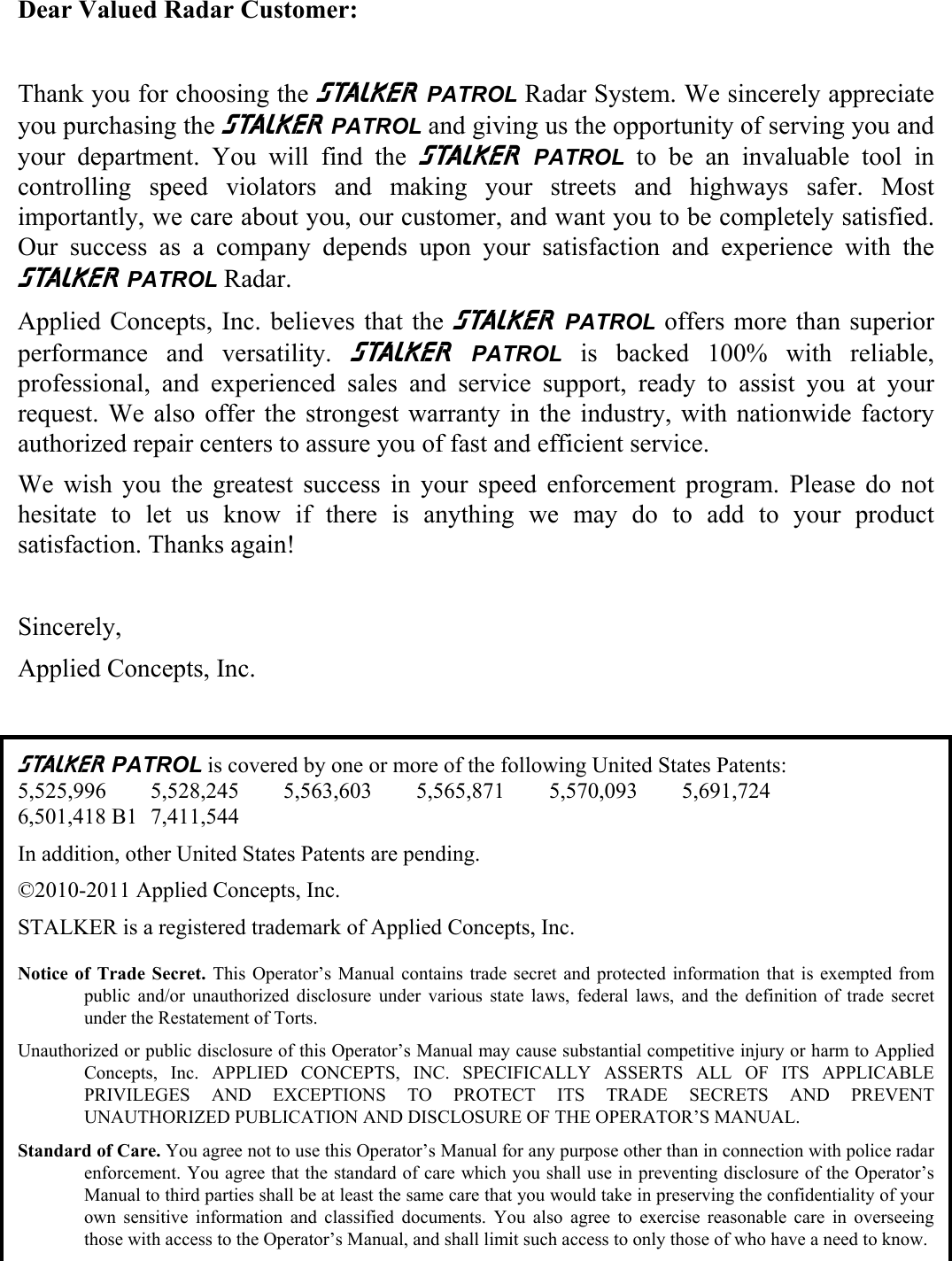

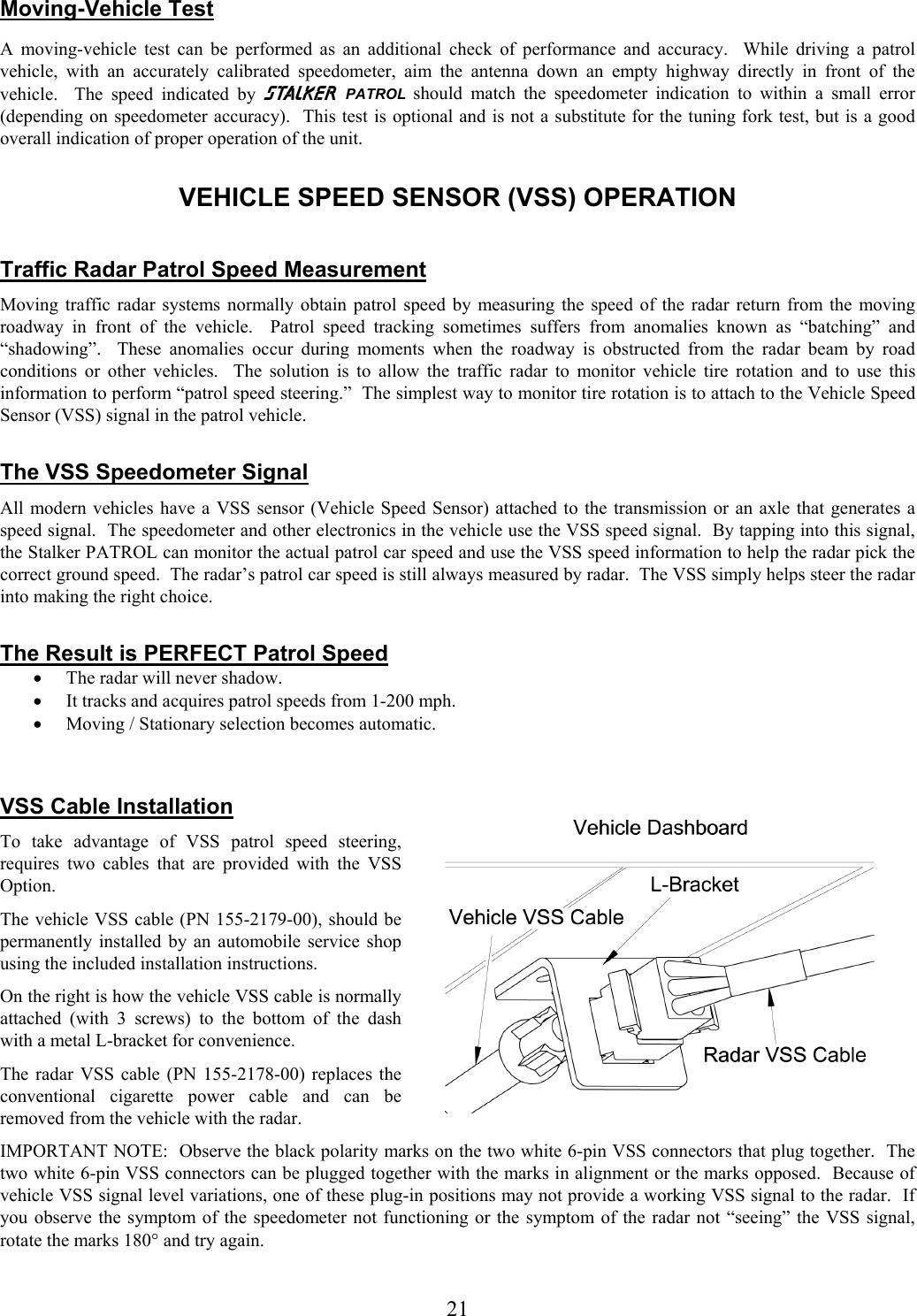
![ERGONOMIC REMOTE CONTROL FUNCTIONS Fig 2 The ergonomic remote control shown above is the standard control supplied with the S PATROL radar unit. Other optional remotes with a different cases and key configurations are shown on later pages. LOCK/REL: In Radar Mode, the LOCK/REL key alternates between target lock and release functions. The first time the LOCK/REL key is pressed, with a speed in the target window, that strong target speed is transferred to the middle window and locked along with the present patrol speed. This state is indicated by the illumination of the LOCK icon. Pressing LOCK/REL a second time clears the locked contents of both the lock and the patrol windows. During lock, the LOCK icon will light. The target window and Doppler audio remain active after locking. MOV STA /MENU: This is a dual function key. The normal function is to toggle between MOVING and STATIONARY modes: A speed or a [ ] in the patrol window indicates moving mode, while a blank patrol window indicates stationary mode. SAME/OPP: The SAME/OPPOSITE key is used to alternate between same lane moving mode and opposite lane moving mode. The SAME icon toggles on and off to indicate same lane mode. ANT: The ANT key is used to switch between the front and rear antennas, unless the radar was factory set for only one antenna. The FRONT or REAR icon will light. The display unit can sense the presence or absence of the front or rear antenna. A steady 5](https://usermanual.wiki/Applied-Concepts/31XXXXXX/User-Guide-1483592-Page-11.png)
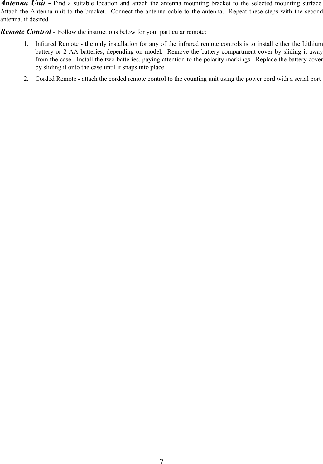
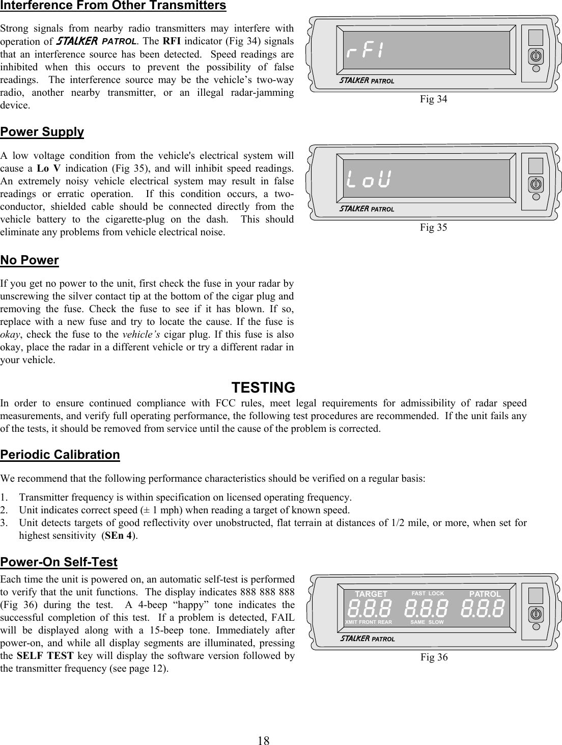
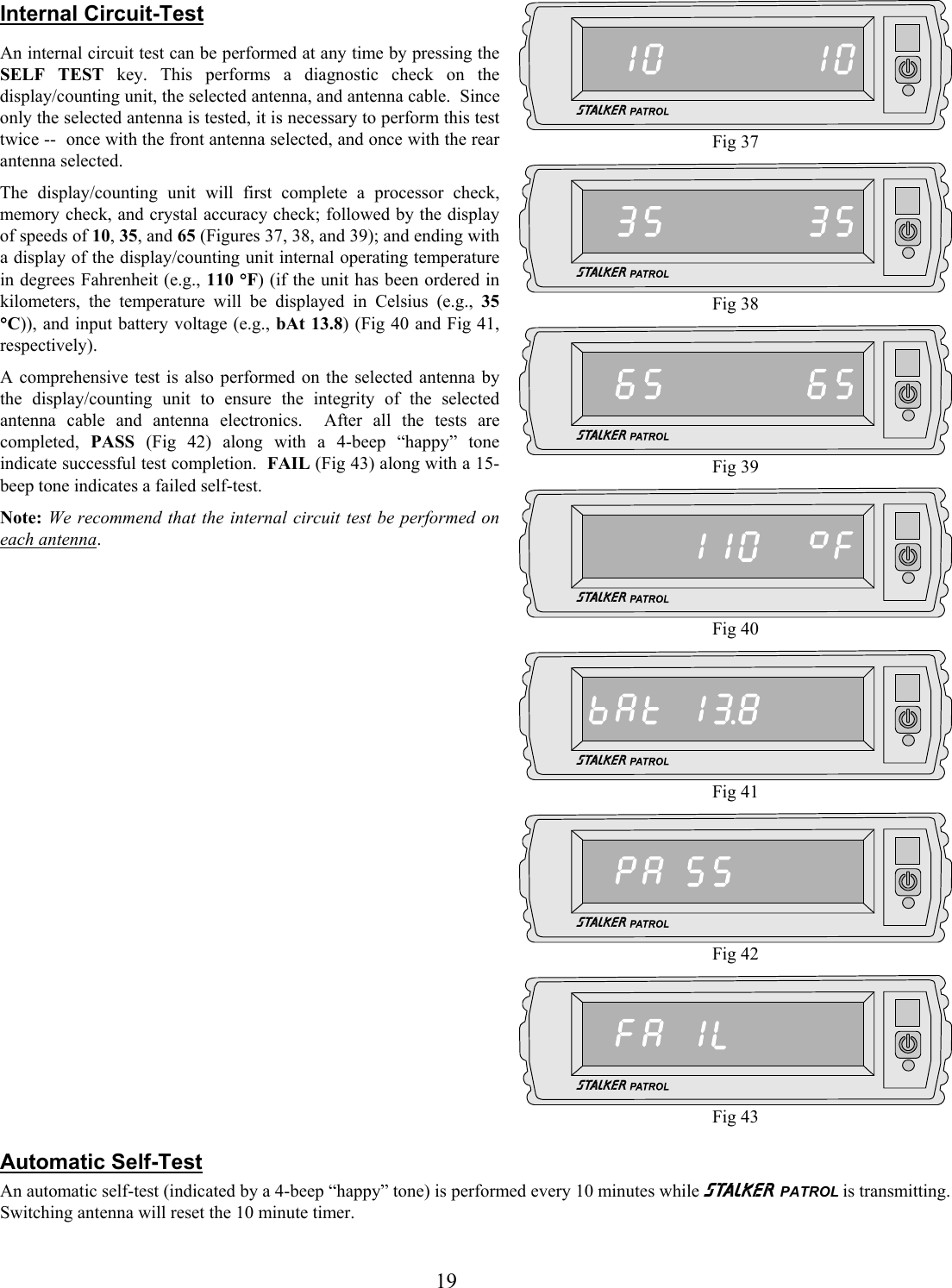
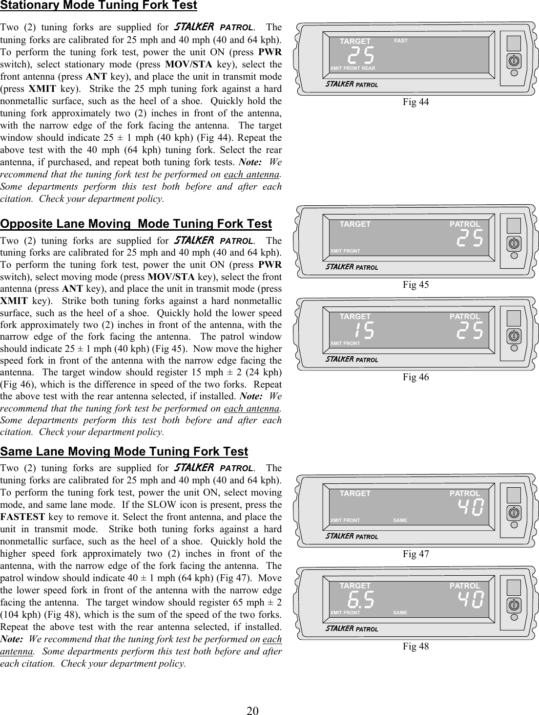
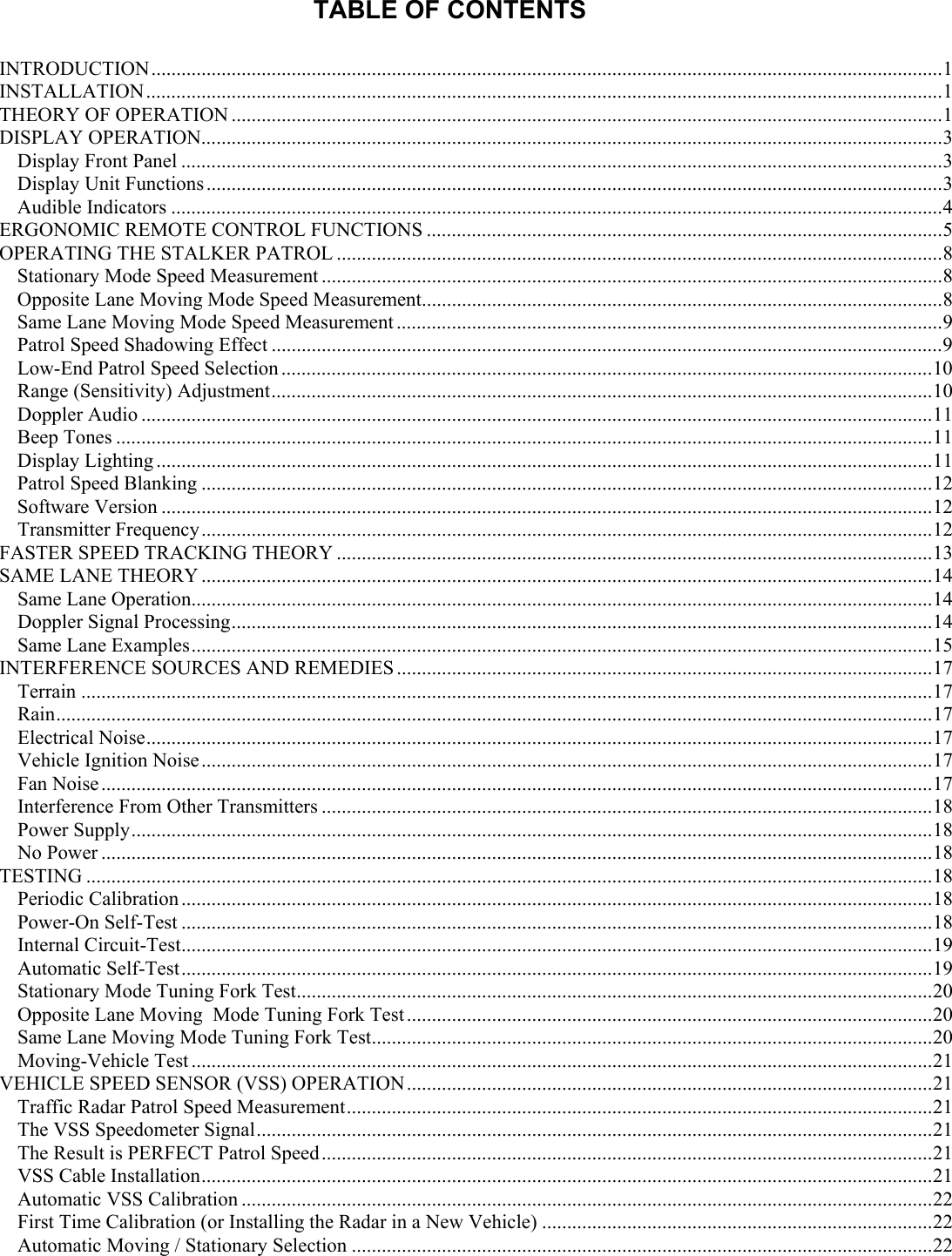
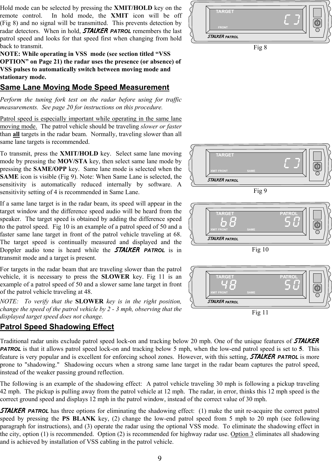
![OPERATING THE STALKER PATROL Stationary Mode Speed Measurement Perform the tuning fork test on the radar before using for traffic measurements. See page 20 for instructions on this procedure. Select stationary mode by pressing the MOV/STA key on the remote control, then select the desired antenna by pressing the ANT key. To transmit, press the XMIT/HOLD key. The XMIT icon should appear on the display unit (Fig 3) indicating that a radar signal is being transmitted. SXMIT FRONT REAR SAME SLOWFAST LOCKTARGET PATROLFi 3 g If a target is in range, such as one traveling 54 mph, the speed will appear in the target window of the display unit (Fig 4); and a Doppler audio tone, which is proportional to the target speed, will be heard from the speaker. The target speed is continually measured and displayed, and the Doppler audio tone is heard as long as the target is present. SXMIT FRONT REAR SAME SLOWFAST LOCKTARGET PATROLFi 4 Hold mode can be selected by pressing the XMIT/HOLD key on the perating in VSS mode (see section titled “VSS of g remote control. In hold mode, The XMIT icon will be off (Fig 5) and no signal will be transmitted, preventing detection by radar detectors. NOTE: While oOPTION” on Page 21) the radar uses the presence (or absence)VSS pulses to automatically switch between moving mode and stationary mode. SXMIT FRONT REAR SAME SLOWFAST LOCKTARGET PATROLFig 5 pposite Lane Moving Mode Speed OMeasurement fork test on the radar before using for traffic ote Perform the tuning measurements. See page 20 for instructions on this procedure. Select moving mode by pressing the MOV/STA key on the remcontrol. When S PATROL is in moving mode, the patrol window will contain either the patrol speed or a [ ]. The [ ] (Fig 6) indicates that S PATROL is in moving mode, but has no ground speed. Select opposite lane mode by pressing the SAME/OPP key until the SAME icon is not visible. To transmit, press the XMIT/HOLD key. The XMIT icon should appear on the display unit (Fig 6) indicating that a radar signal is being transmitted. Be sure the patrol speed indicated corresponds to the speedometer of the patrol vehicle. If an approaching target is in the radar beam, its speed will appear in the target window and a Doppler audio tone will be heard from the speaker. Fig 7 is an example in which the patrol speed is 50 and the approaching target speed is 68. The target speed is continually measured and displayed and the Doppler audio tone is heard while the S PATROL is in transmit mode and a target is present. SXMIT FRONT REAR SAME SLOWFAST LOCKTARGET PATROLFig 6 SXMIT FRONT REAR SAME SLOWFAST LOCKTARGET PATROLFig 7 8](https://usermanual.wiki/Applied-Concepts/31XXXXXX/User-Guide-1483592-Page-14.png)
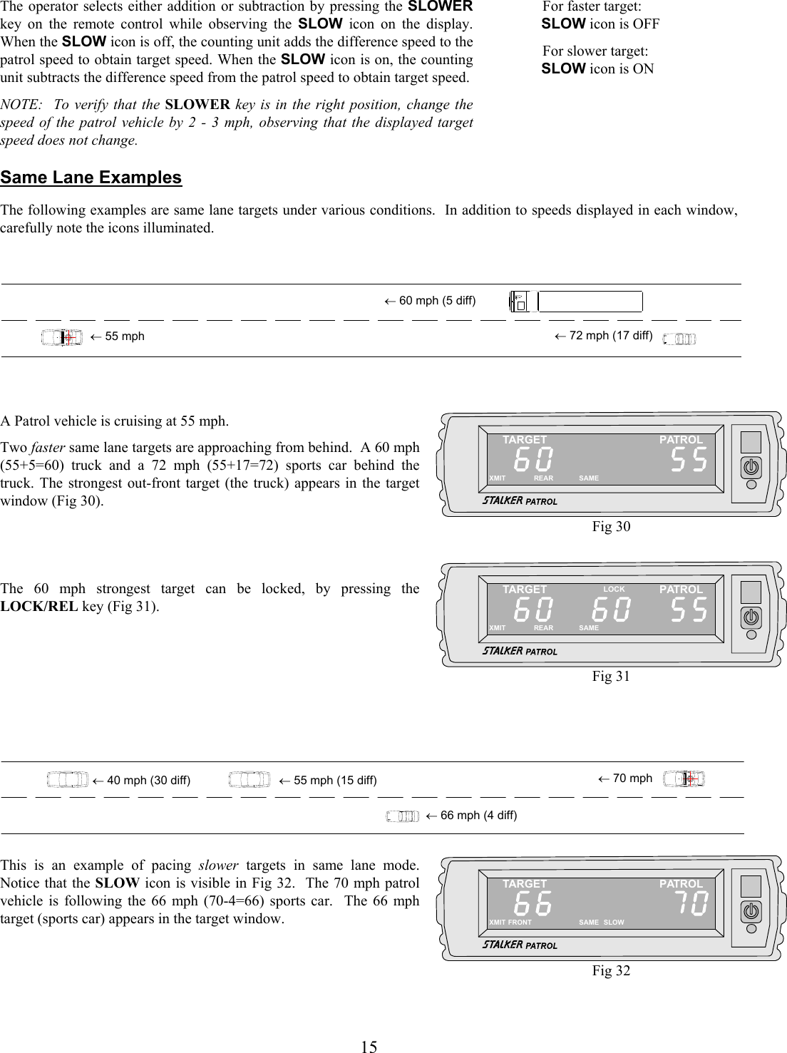
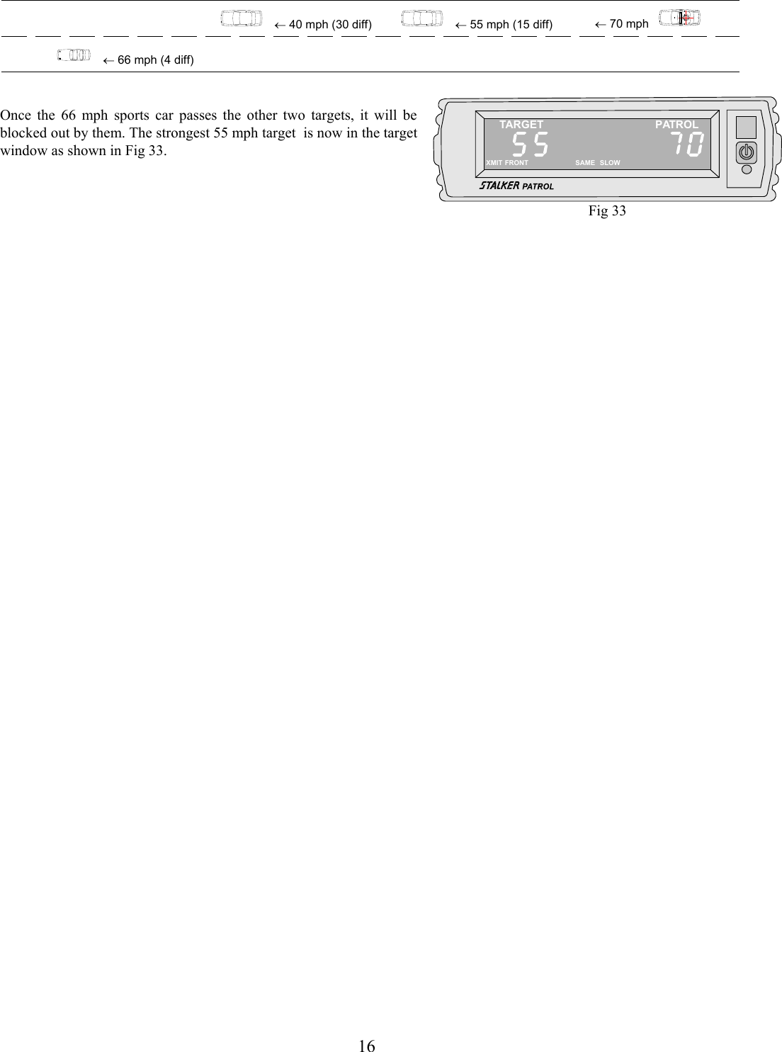
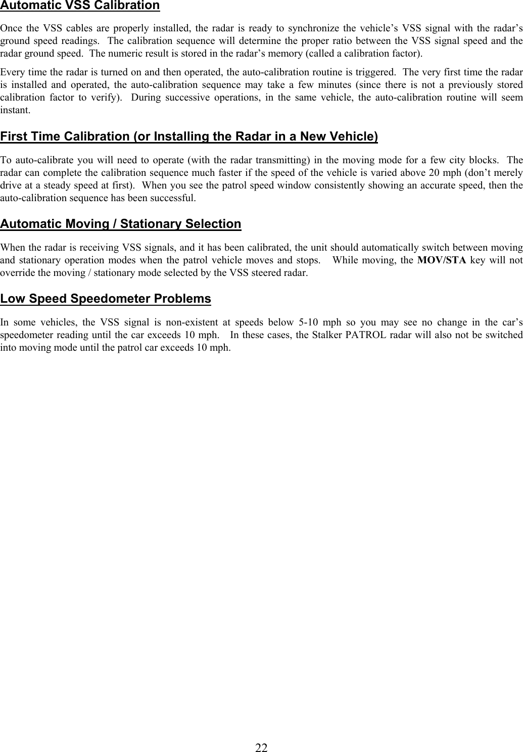
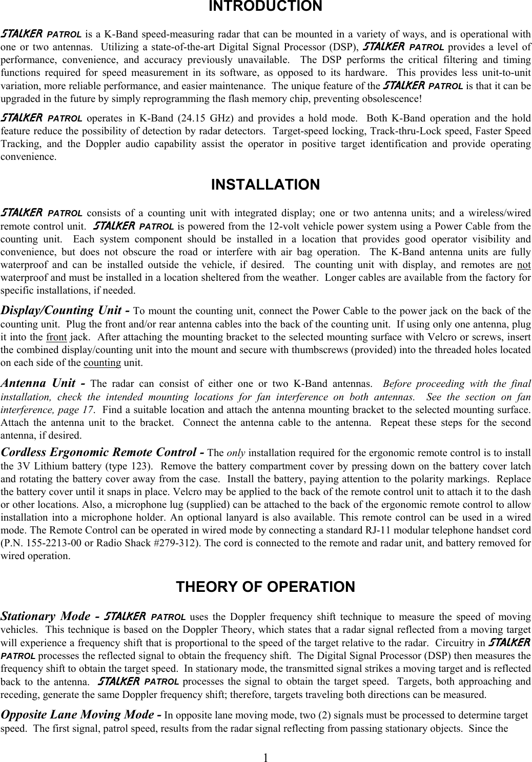
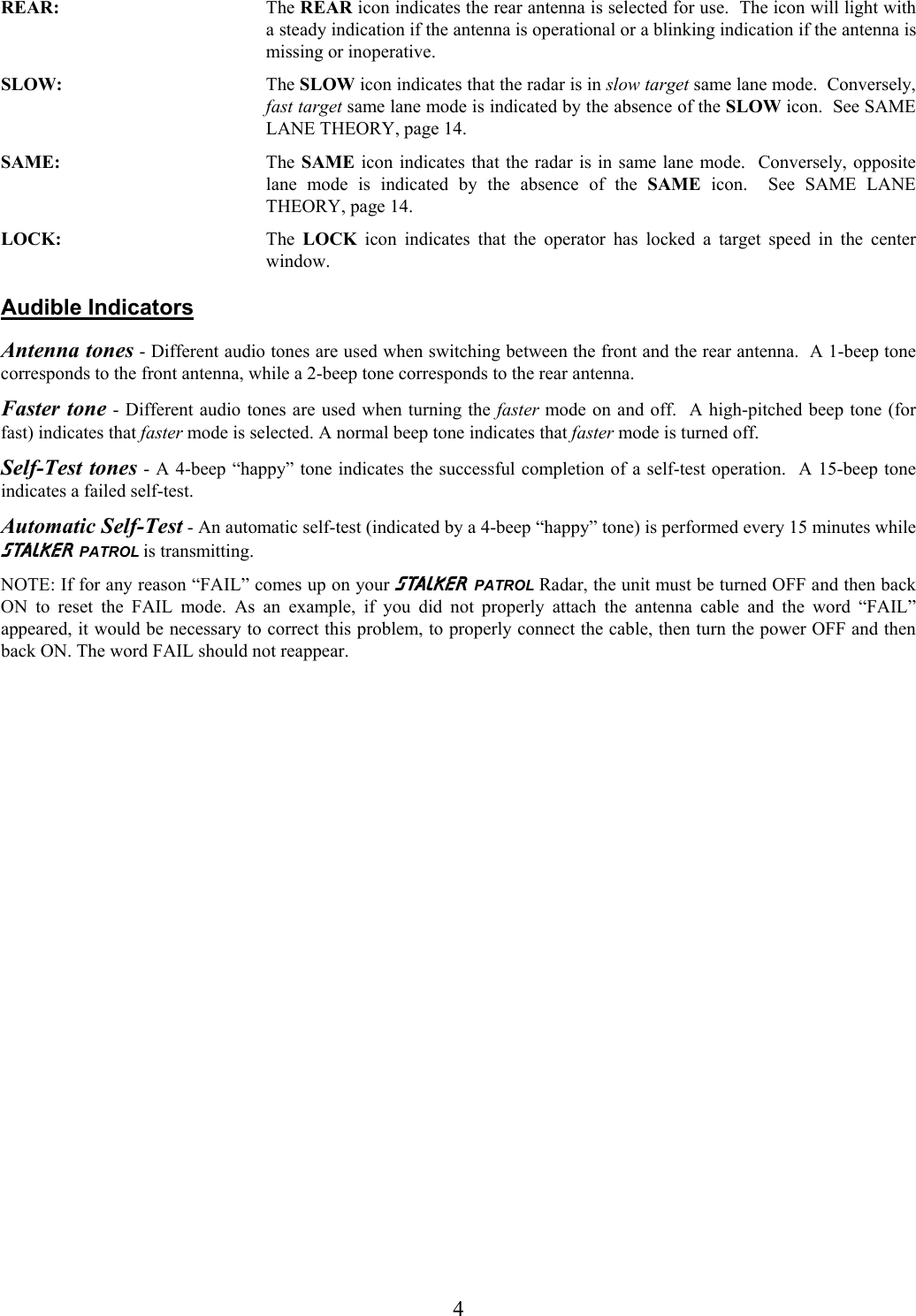
![A Patrol vehicle is parked at the top of a hill monitoring approaching traffic with his rear antenna. The first target, a 60 mph truck, is the strongest out-front target and appears in the target window (Fig 29). The third target, the 72 mph Faster sports car, is tracked in the middle Faster window. The Faster target can be locked by pressing the LOCK key when it becomes the strongest target. SXMIT FRONT REAR SAME SLOWFAST LOCKTARGET PATROL Fig 29 SAME LANE THEORY Same Lane Operation 1. To transmit, press the XMIT/HOLD key. The XMIT icon should appear on the display indicating a radar signal is being transmitted. 2. Select moving mode by pressing the MOV/STA key on the remote control. When S PATROL is in moving mode, the patrol window will contain either the patrol speed or a [ ]. The [ ] indicates that S PATROL is in moving mode, but has no ground speed. Be sure the patrol speed indicated corresponds to the speedometer of the patrol vehicle. 3. Then select same lane mode by pressing the SAME/OPP key. Same lane mode is selected when the SAME icon is visible. 4. If a target is in the radar beam, its speed will appear in the target window and a Doppler audio tone will be heard from the speaker. 5. Patrol speed is especially important while operating in the same lane moving mode. The patrol vehicle should be traveling slower or faster than all targets in the radar beam. Normally, traveling slower than all same lane targets is recommended. After visually estimating the speed of the targets in the radar beam, press the SLOWER key to correspond to whether the observed targets are traveling faster or slower than the patrol vehicle. The SLOW icon indicates that the target is traveling slower. 6. To verify that the SLOWER key is in the right position, change the speed of the patrol vehicle by 2-3 mph, observing that the displayed target speed does not change. ExampleDoppler Signal Processing Two signals must be processed to determine target speed. The first signal, patrol speed, results from the radar signal reflecting from passing stationary objects. The Doppler shift of this signal will be proportional to the speed of the patrol vehicle, since Doppler shift is proportional to the relative velocity between the radar and the passing reflecting objects. Patrol Speed = 55 mph The second signal, difference speed, results from the radar beam reflecting from a slower or faster same lane moving target and then returning to the patrol vehicle. The Doppler shift of this signal will be proportional to the difference speed between the patrol and target vehicles. The audio tones heard while in same lane mode are directly related to this difference speed. Difference Speed = 10 mph The radar is unable to distinguish between a difference speed resulting from a faster or slower target. The operator must tell the radar how to process this signal by pressing the SLOWER key. If the target vehicle is moving faster than the patrol vehicle, the difference speed must be added to patrol speed to obtain target speed. If the target vehicle is moving slower than the patrol vehicle, the difference speed must be subtracted from the patrol speed to obtain target speed. For faster target: Target = 55+10 = 65 For slower target: Target = 55-10 = 45 14](https://usermanual.wiki/Applied-Concepts/31XXXXXX/User-Guide-1483592-Page-20.png)