Applied Wireless Identifications Group MR1824A Proximity Reader Transceiver User Manual 1 of 2
Applied Wireless Identifications Group Inc. Proximity Reader Transceiver 1 of 2
Contents
- 1. User Manual 1 of 2
- 2. User Manual 2 of 2
User Manual 1 of 2

Installation Sheet (Wiegand Interface) (Part No. 004-98-A)
Sentinel-Prox MR-1824 Reader
Reader Description Revision E August 15, 2006
The Sentinel-Prox MR-1824 Reader is a medium-range radio-frequency proximity reader for Gate Control and
Access Control Systems. The Reader consists of a transmit/receive antenna and reader electronics in
a polycarbonate housing. The reader electronics are potted with epoxy resin to protect against the environment.
MR-1824 may be mounted on any non-metallic surface. MR-1824-MC is a metal-compensated version of this
reader for mounting on or near a metal surface; see the attached sheet for notes on installing MR-1824-MC.
Parts List
(a) Installation sheet, P/N 004-98-A Qty=1
(b) Sentinel-Prox MR-1824 Reader, P/N 004-20-A Qty=1
(c) #6-20 x 1.375” self-tapping screw, P/N 004-30-A Qty=4
(d) Plastic anchor, P/N 004-30-B Qty=4
(e) Screw-hole plug, P/N 004-27-A Qty=5 (1 spare)
(f) Cable slot plug, P/N 004-27-B Qty=2
(g) Ferrite clamp, P/N FC Qty=1
Installation Procedure (Installation notes for MR-1824-MC are on attached sheet.)
1. Position the reader (item b in the Parts List) at the desired location. Observe ADA height requirements.
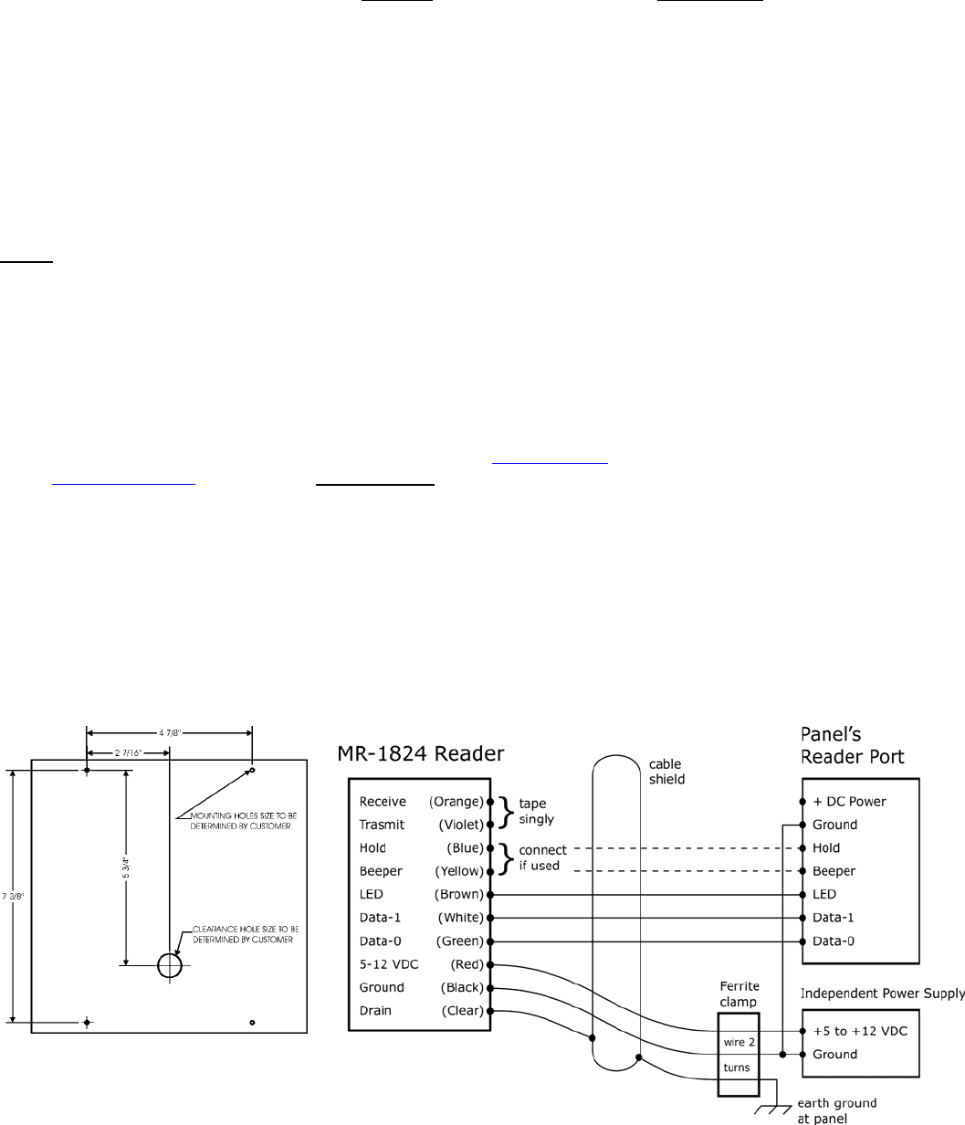
Drill four holes for the screws or anchors, and drill one clearance hole for the cable (see Figure 1).
The installer determines the size of mounting holes and cable clearance hole.
2. Clip off the white 10-pin connector from the end of the reader’s cable. Keep the wires as long as possible.
3. Connect the reader’s cable to the controller panel as shown in Figure 2. Connect the yellow wire only if used
for Beeper control by the panel. Connect the blue wire only if used for Hold control by the panel. Do not connect
the orange and violet wires to anything. Tape or cap all unused wires singly.
4. Use a linear regulated DC power supply, between 5 volts (250 mA) and 12.0 volts maximum (600 mA peak).
Do not power the MR-1824 from the panel’s internal power supply – use an external DC power supply.
For guaranteed performance, order P/N PS12-1A from AWID. Tie the ground side of all DC circuits together –
including the reader, the panel’s reader input port, the external power supply, and the door or gate release.
5. Install the ferrite clamp (Parts List item g) on the +DC power, DC ground, and drain wires. See instructions on page 3.
6. To install the reader’s cable through the wall directly behind the reader, insert both cable slot plugs (item f in
the Parts List) in the sides of the reader’s top cover. To run the cable exiting from the side of the reader, press-fit
the cable into the curved channel and guide the cable out of the desired side of the reader. Then insert the cable
slot plug in the other side of the top cover.
7. Install the reader on the mounting surface, using screws (item c) and anchors (item d) as necessary.
8. Power up the reader. The LED should be steady amber. (The beeper does not sound.)
9. Present a valid AWID proximity credential (card, keytag or wafer) briefly to the reader. The beeper sounds a single
Short beep. The LED is steady red to indicate Standby mode. The reader is now initialized and can read cards.
Note: All credentials must be AWID’s products.
10. The LED color in Standby mode may be changed from red to green, or from green to red, using a Color Changer card,
available from AWID. Remove power from the reader for a few seconds, then restore power. While the LED
is amber, present the Color Changer card to toggle the LED’s Standby color.
11. When installation is complete, insert screw-hole plugs (item e in the Parts List) into the screw clearance holes
to conceal the screw heads. Note: Screw-hole plugs are for one-time use. After they are seated, they cannot
be removed without damaging the plugs.
Product Specifications
Material of the mounting surface
• MR-1824.................................. Non-metallic material only (Keep the reader at least 3 inches from all metal.)
• MR-1824-MC .......................... Any material including metal (continued)
Cable to Controller (for basic connections)
• 5, 6 or 7 conductors (not twisted pairs), stranded, 22 AWG, color-coded insulation, overall 100% shielded
(Number of conductors depends upon use of optional features – Beeper, Hold and LED. See Figure 2.)
• Length for Wiegand Interface................ Up to 500 feet
Read Range (Typical) MR-1824 MR-1824-MC
• At 5 VDC................................. About 12 inches (30 cm) ...............................About 8 inches (20 cm)
• At 12 VDC............................... 18 to 24 inches (45 to 60 cm) ........................Up to 16 inches (40 cm)
Characteristics
• Indoor and Outdoor ................. Rated for outdoor installations
• Operating Temperature............ -35° C to 65° C (-31° F to 150° F)
• Operating Humidity................. 0 to 95% non-condensing
Operating Parameters
• Excitation Frequency............... 125 kHz
• Wiegand Output....................... 26 bits to 50 bits (as programmed in the cards or tags))
Certifications.......................................... FCC Part 15 certification; Industry Canada
Notes
1. For suggestions on best performance, read AWID’s memo “MR-1824 – Achieving Maximum Read Range”.
2. When the yellow wire is not used, the beeper remains active and under the reader’s internal control.
3. Beeper, Hold, and LED lines are logic levels. Never apply power to them. They may be pulled to a low level
(0 to 1.2 VDC) to enable their function, and left floating at a high level (3.6 to 5.0 VDC) when not used.
4. MR-1824 and MR-1824-MC readers have both Wiegand-protocol and RS-232 interfaces. For information on RS-232,
contact AWID’s technical support.
5. For additional information, please see AWID’s web site (www.awid.com). Send all technical support questions
to support@awid.com. Call AWID at 1-800-369-5533 from 8:00 a.m. to 7:00 p.m. Eastern Time.
6. FCC Compliance: This equipment has been tested and found to be in compliance with the limits for FCC part 15, Class A digital device.
These limits are designed to provide reasonable protection against harmful interference when the equipment is operated in a commercial
environment. This equipment generates, uses and can radiate radio frequency energy and, if not installed and used in accordance with
instruction manual, may cause harmful interference with radio communications. Operation of this equipment in a residential area is
likely to cause harmful interference in which case the user will be required to correct the interference at his own expense.
The users are prohibited from making any change or modification to this product. Any modification to this product shall void the
user’s authority to operate under FCC Part 15 Subpart A Section 15.21 regulations. This device complies with Part 15 of the FCC Rules.
Operation is subject to the following two conditions: (1) This device may not cause harmful interference, and (2) this device must
accept any interference received, including interference that may cause undesired operation.
7. Industry Canada Compliance: Operation is subject to the following two conditions: (1) This device may not cause harmful
interference, and (2) this device must accept any interference, including interference that may cause undesired operation of the device.
FIGURE 1. Holes Location FIGURE 2. Wiring Diagram (Wiegand)
MR-1824 Revision E Reader Installation Sheet 15 August 2006 Page 2 of 3
MR-1824 Revision E Reader Installation Sheet 15 August 2006 Page 3 of 3
Installation Sheet (Wiegand Interface) (Part No. 004-97-A)
Sentinel-Prox MR-1824 Reader
Instructions
INSTALLING FERRITE CLAMP ON POWER SUPPLY CABLE
To meet the requirements of the FCC, AWID supplies a “ferrite clamp” for installation on the power
supply wiring. The clamp can be installed by hand, easily and quickly, at the site, without removing
the reader or its wiring. This procedure may be used on a power supply that was installed earlier, or
on one being newly installed.
Three wires must pass through the ferrite’s channel when it is snapped closed – (a) the positive DC,
(b) the DC ground, and (c) the drain wire from the reader and the cable’s shield to earth-ground.
1. Locate the low-voltage DC power supply and the wires that connect it to the MR-1824 reader or
the MR-1824-MC reader.
2. Arrange for enough excess wire length so that the wires can loop through the ferrite clamp with two turns
of the wires inside the channel of the clamp.
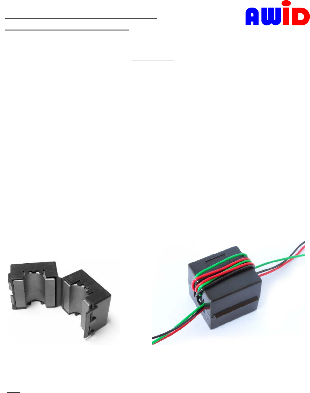
3. Hold the open clamp (Figure 1) at a place where the three wires are accessible.
4. Loop the wires twice around the channel in the ferrite. Pull the wire loop tightly around the ferrite clamp.
5. Press the ferrite clamp around the wires until the latch at one end of the clamp snaps over the ears on the other
end of the clamp. (See Figure 2.)
FIGURE 3. Ferrite clamp (open) FIGURE 4. Ferrite clamp locked on 3 wires
Note: If it is necessary to remove the ferrite clamp from the wires, insert a fingernail under the latch and lift it
off the ears. The clamp will then swing open.