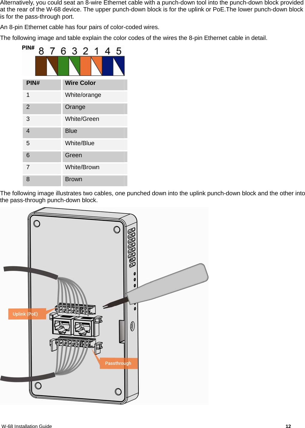
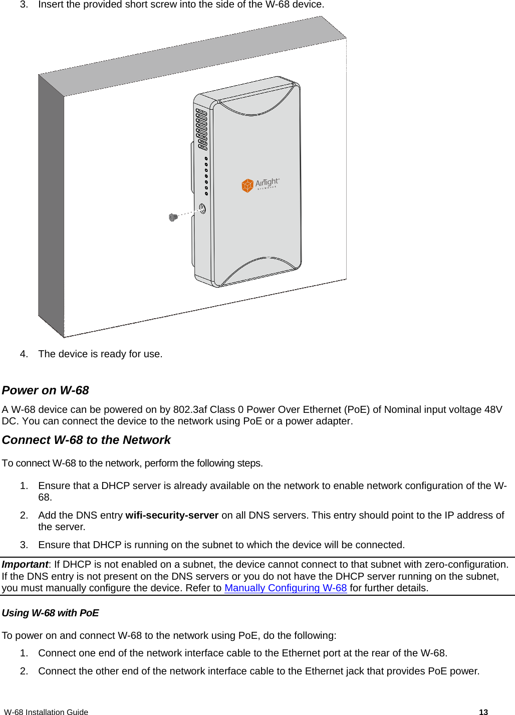
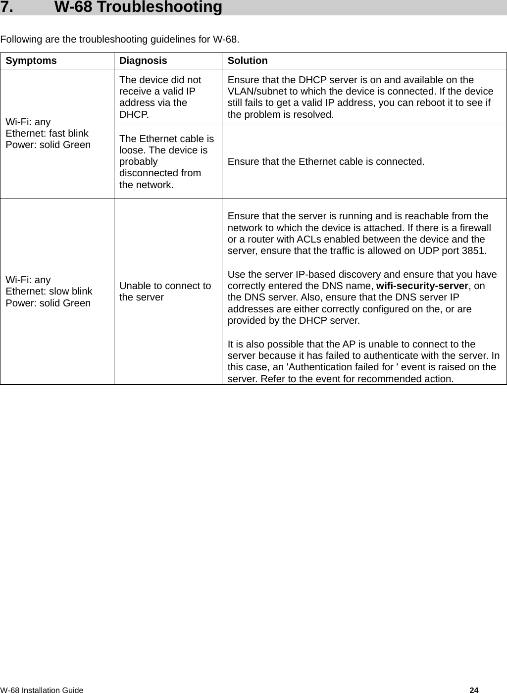
Arista Networks W68 Access Point/Sensor User Manual W 68 Installation Guide
AirTight Networks, Inc. Access Point/Sensor W 68 Installation Guide
UserManual.wiki
>
Arista Networks
>
W68 User Manual
>
(W-68) UserMan_20150127
Contents
1.
User manual
2.
(W-68) UserMan_20150127
(W-68) UserMan_20150127
Navigation menu
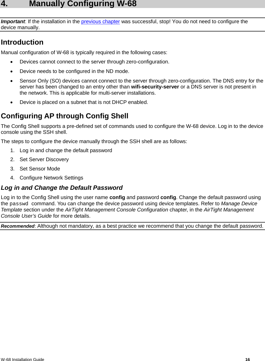
Upload a User Manual
Namespaces
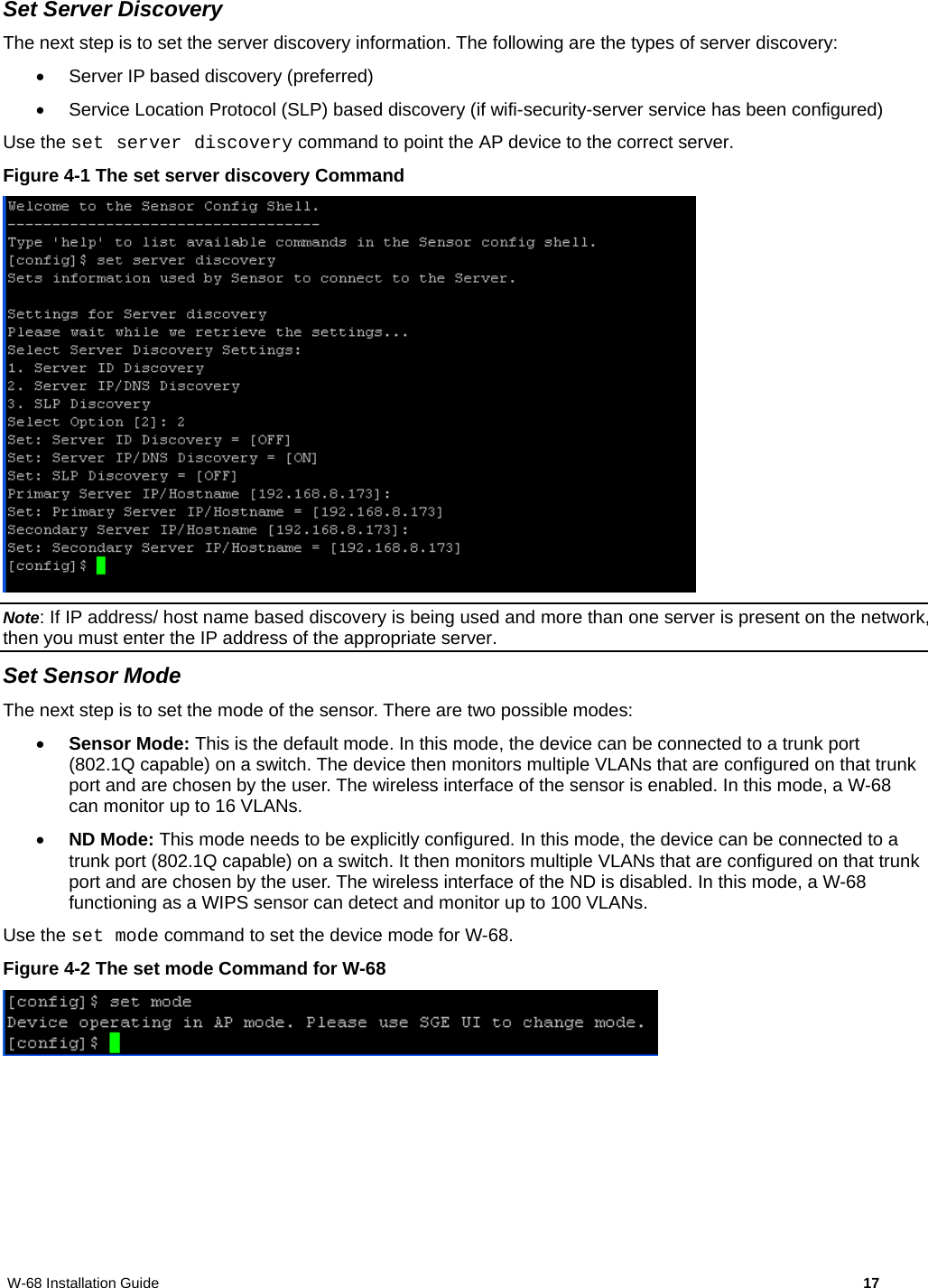
Wiki Guide
HTML
PDF
Info
Views
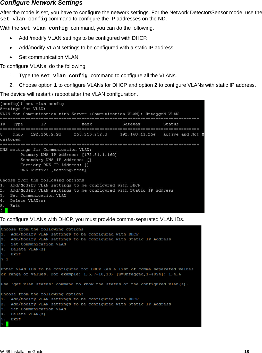
User Manual
Discussion / Help
Navigation