Astronics CSC E7130801 Wireless Access Point User Manual 20171030 v1 11 11669553 v4 UM E71 308 01 Rev C
Telefonix, Inc. Wireless Access Point 20171030 v1 11 11669553 v4 UM E71 308 01 Rev C
Contents
- 1. 11_11669553 v3 UM-E71-308-01 Rev C
- 2. User Manual_20171030_v1 - 11_11669553 v4 UM-E71-308-01 Rev C
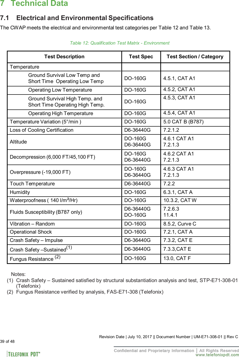
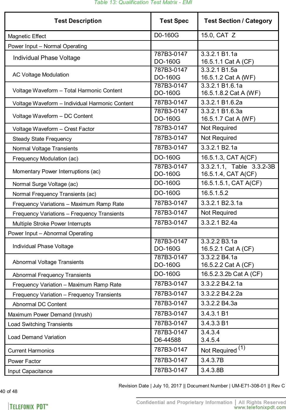
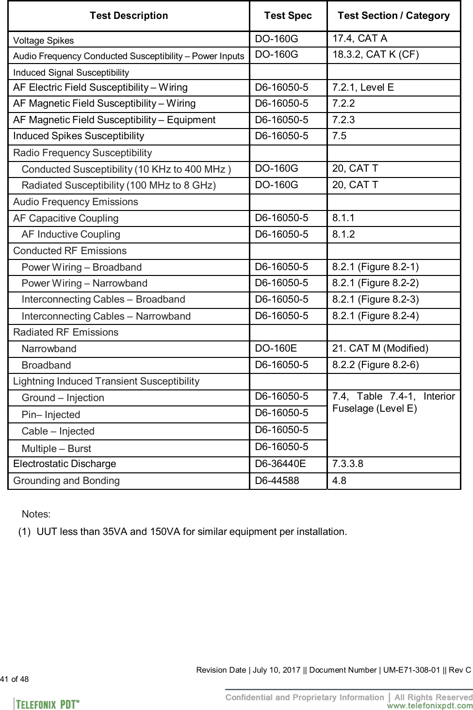
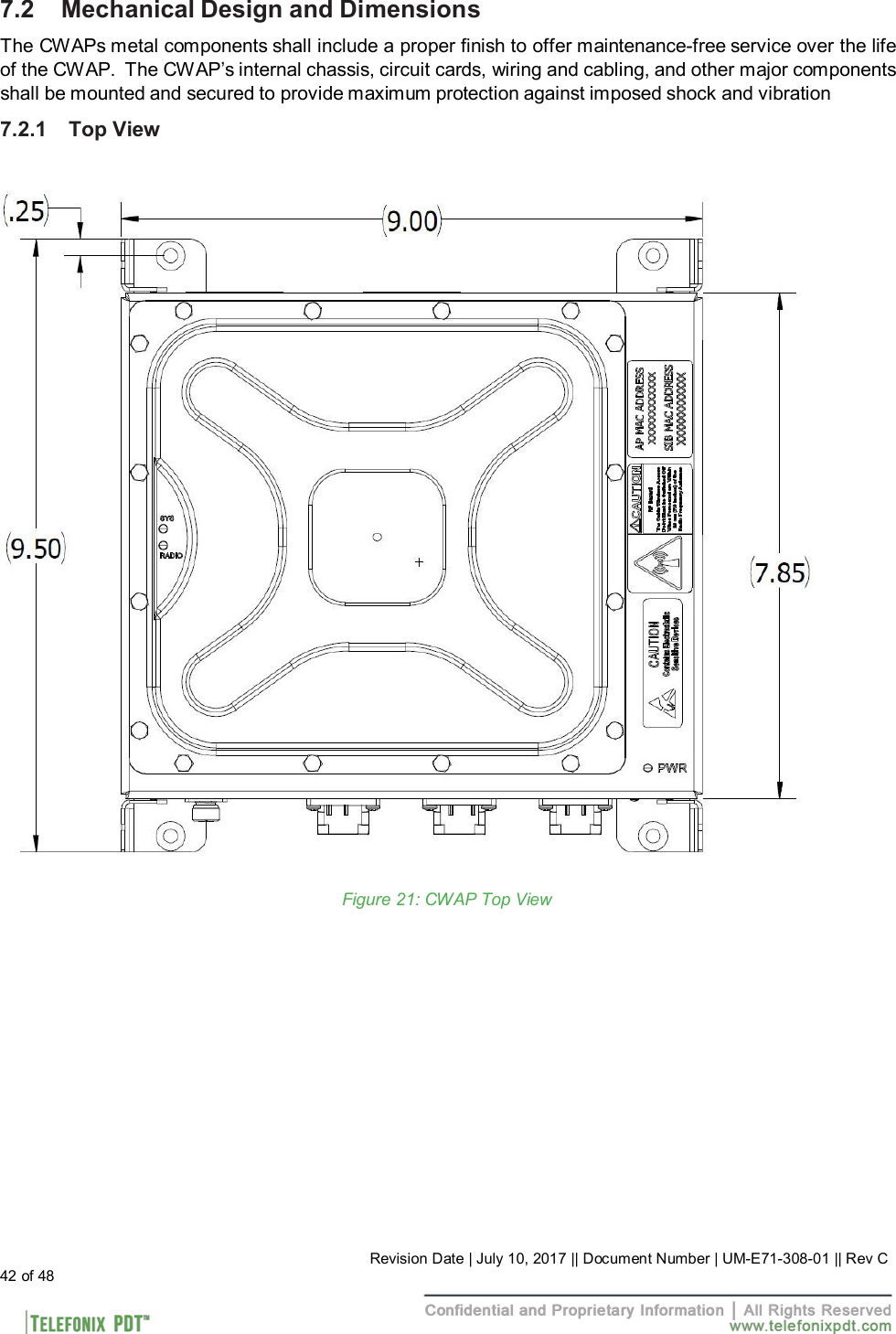
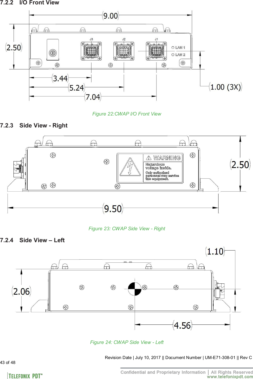
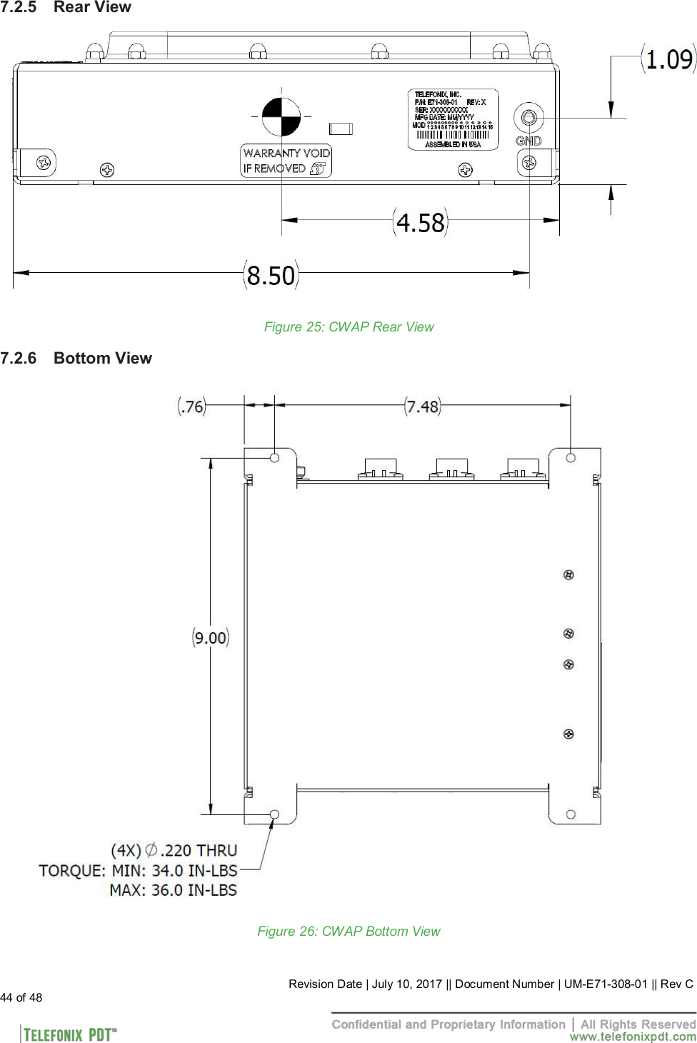
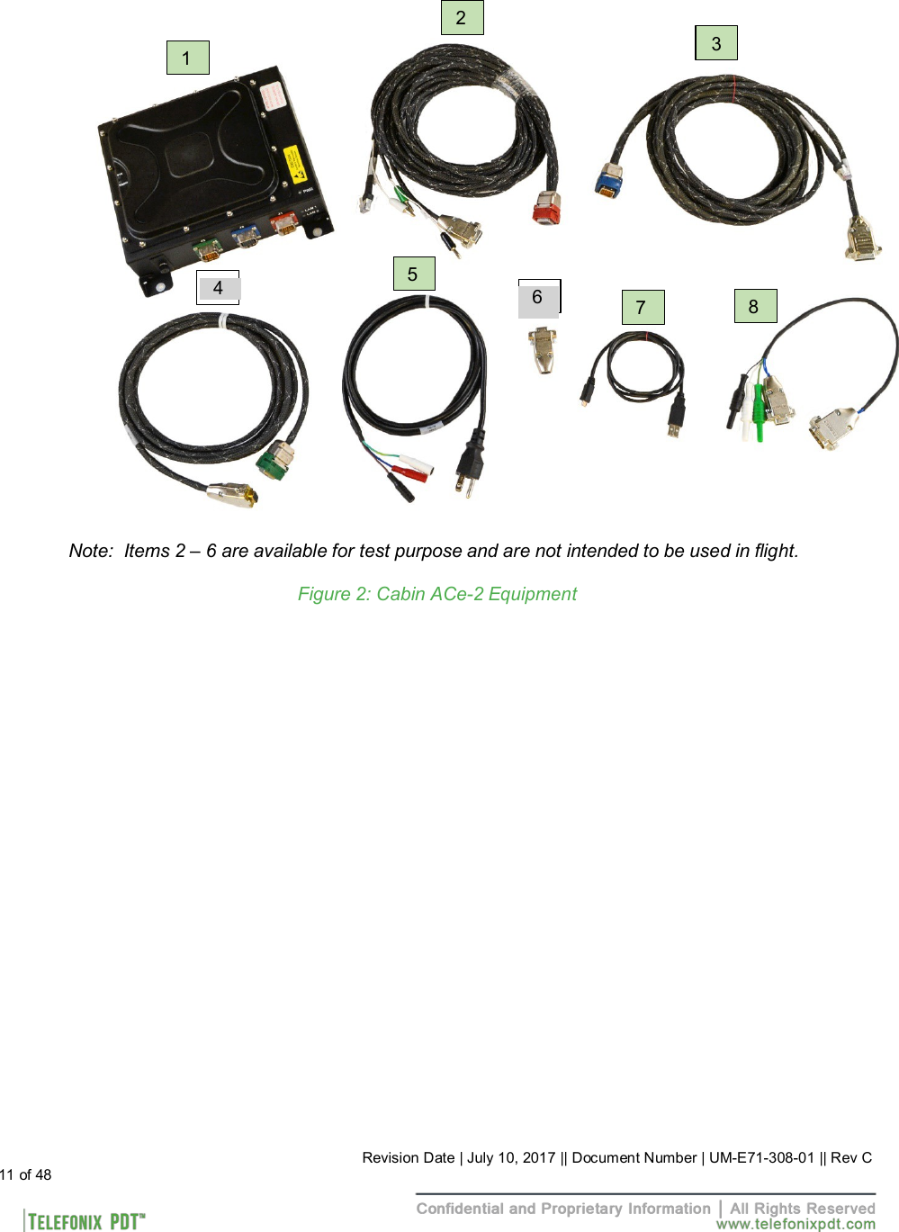
User Manual_20171030_v1 - 11_11669553 v4 UM-E71-308-01 Rev C
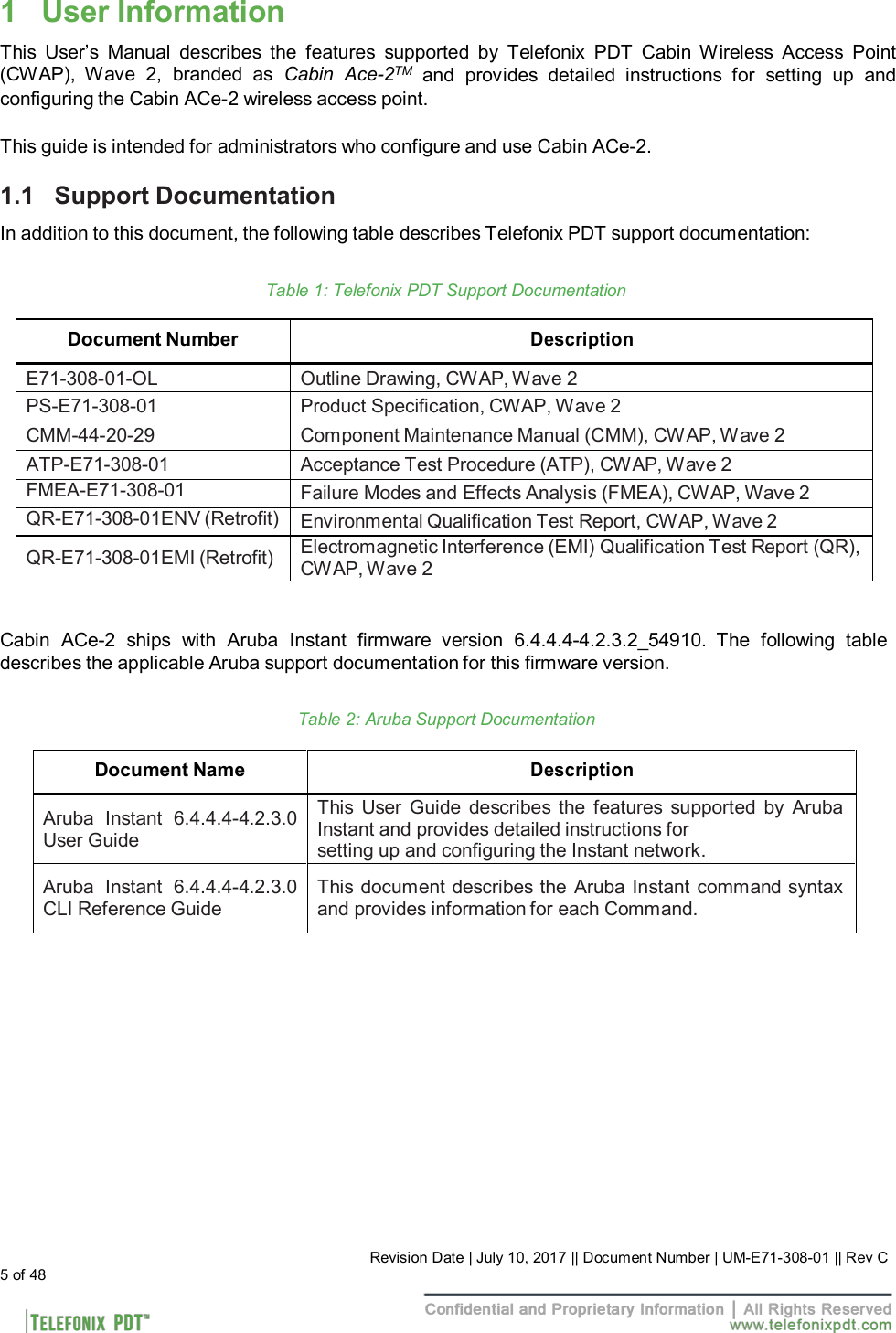
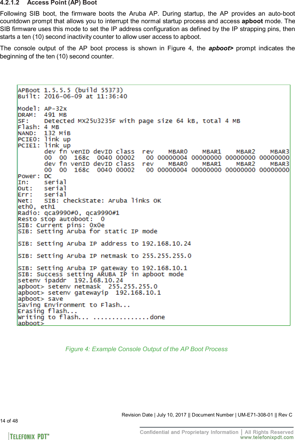
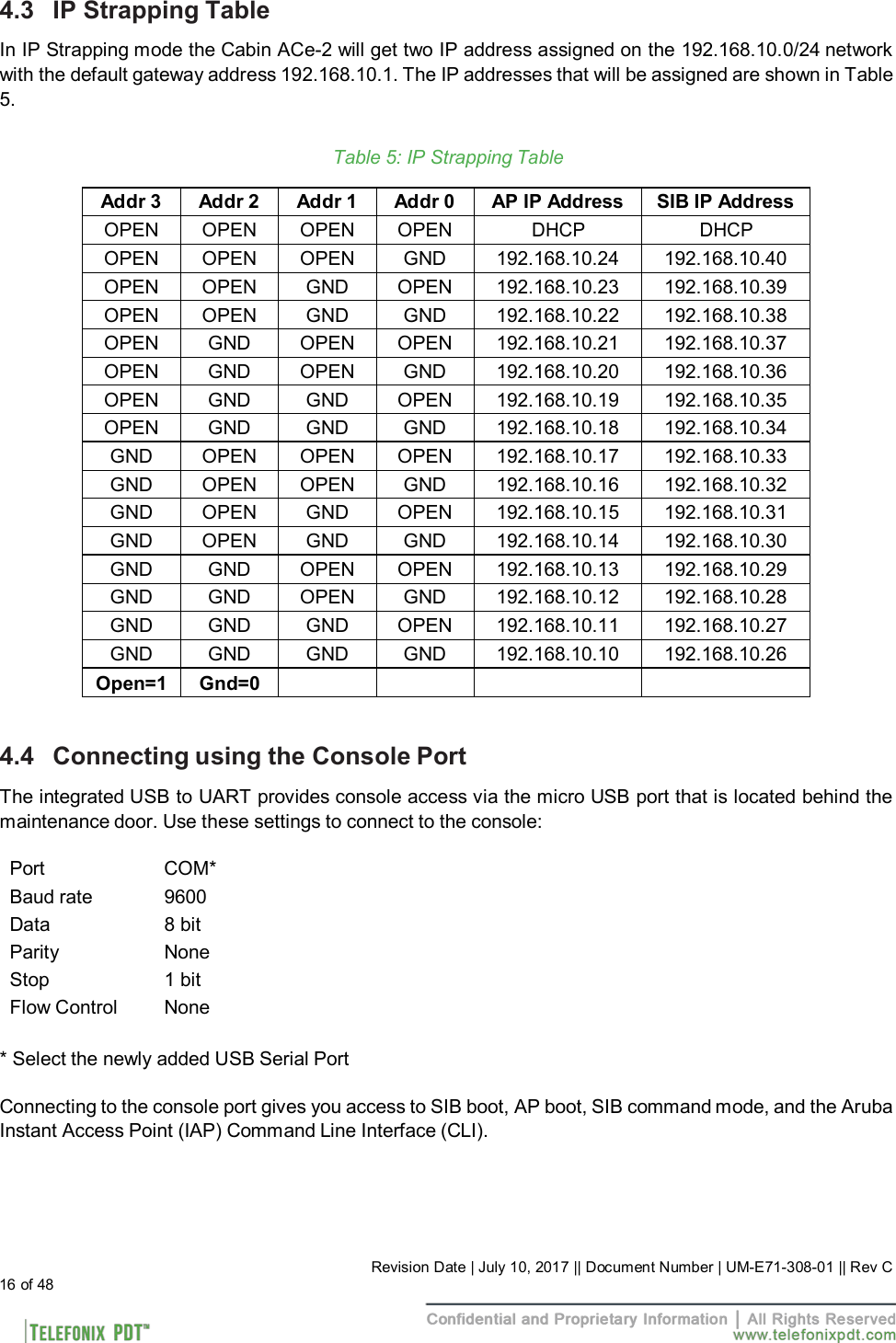
![4.2.1 Boot Up 4.2.1.1 SIB Boot Up The SIB runs both the bootloader and application firmware components upon powering on the unit. There is a two (2) second delay before the firmware loads to allow the bootloader to check for the presence of a SIB firmware upgrade. During startup, the firmware performs a Power On Self-Test (POST), queries the discrete pins, and reads the SIB configuration and manufacturing data from an internal EEPROM. After the boot process completes there is a five (5) second window in which you may be asked to enter SIB command mode by your technical service representative. The console output of the SIB boot process is shown in Figure 3, the [Boot Complete] prompt indicates the beginning of the five (5) second delay. Figure 3: Example Console Output of the SIB Boot Process 13 of 48 Revision Date | July 10, 2017 || Document Number | UM-E71-308-01 || Rev C](https://usermanual.wiki/Astronics-CSC/E7130801.User-Manual-20171030-v1-11-11669553-v4-UM-E71-308-01-Rev-C/User-Guide-3666881-Page-13.png)
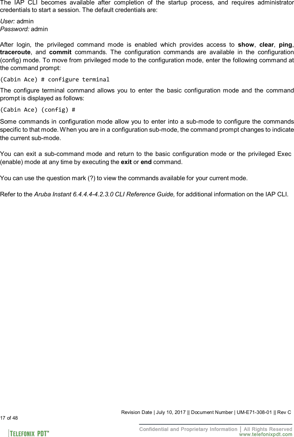
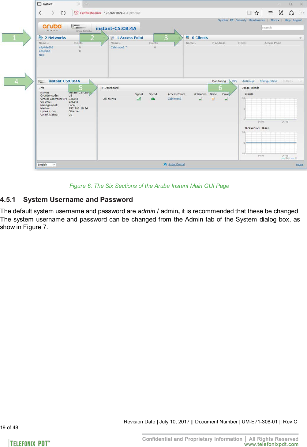
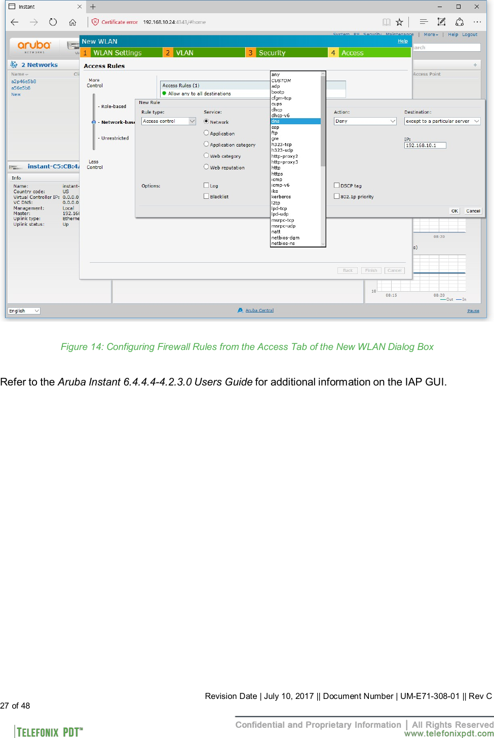
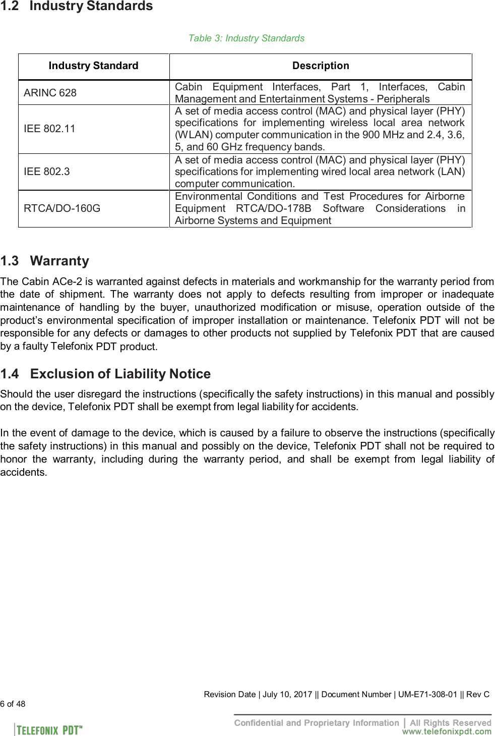
![4.5 Connecting using Web-based GUI You can connect to the web-based GUI by entering the Aruba AP’s IP address in a web browser, and entering the Username and Password when prompted as shown below in Figure 5. If the IP strapping pins have not been set, you can use the show ip interface CLI command to display the IP address that was assigned by your DHCP server Note: The following subsections refer to the [Aruba] IAP, or AP which shall be used interchangeably with the CWAP. The sections are summarized from Aruba Instant documentation and training materials. For additional information refer to the Aruba Instant 6.4.4.4-4.2.3.0 User Guide. Figure 5: Aruba Instant GUI Login Prompt You may see a Certificate Error message, this is because the certificates issued to the AP do not match the IP address used to connect to the GUI. It is recommended that you add a certificate issued by your network, to ensure secure administrative communication. The main GUI page is broken up into the following six sections. These sections are identified below in Figure 6. 1. Networks – Show all the wireless networks associated with this cluster. 2. Access Points – Shows all the access points in the cluster, the * indicates the Virtual Controller. 3. Clients – Shows all the clients connected to access points in this cluster. 4. Instant AP information – Basic information on the Virtual Controller of this cluster. 5. RF Dashboard – Gives you a view of all clients RF signals and other issues. 6. Usage Trends – Shows all the clients and throughput generated by all the clients on this cluster. 18 of 48 Revision Date | July 10, 2017 || Document Number | UM-E71-308-01 || Rev C](https://usermanual.wiki/Astronics-CSC/E7130801.User-Manual-20171030-v1-11-11669553-v4-UM-E71-308-01-Rev-C/User-Guide-3666881-Page-18.png)