Autel Intelligent Tech MAXISYSMS906TS MaxiSys MS906TS User Manual Part Two
Autel Intelligent Tech. Corp., Ltd. MaxiSys MS906TS Users Manual Part Two
Contents
- 1. Users Manual Part Two
- 2. Users Manual Part One
- 3. Users Manual part One
Users Manual Part Two
67
Chapter 6 MaxiFix Operations
The MaxiFix application launches the on-line troubleshooter database, which not only
provides you virtually all common diagnostic trouble code (DTC) database for most
vehicles, but also serves as a forum allowing you to network with other MaxiSys users,
and gives you access to a vast database of repair and diagnostic tips along with proven
filed fixes.
While the MaxiFix provides the abundant troubleshooter information available, the
database keeps growing with daily troubleshooting resources by recording the reported
solution cases, and the advisory reports of the MaxiSys users from all over the world.
Information in the MaxiFix database is organized into a series of diagnostic tips that are
designed to quickly lead you to the root cause of a particular problem on the test vehicle,
which will help you quickly find solutions for various diagnostic problems.
6.1 Navigation
You need to register the device to your online account before launching the
MaxiFix platform, see 12.1 Product Registration on page 99 for details.
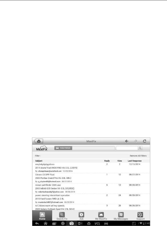
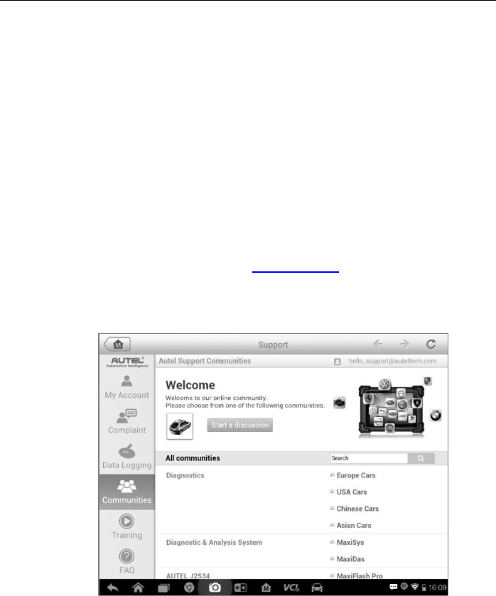
Figure 6-1 Sample MaxiFix Home Page

MaxiFix Operations Navigation
68
The MaxiFix screen layout consists of 3 main areas:
1. The Header –the tool bar across the top of the screen which allows you
to select vehicles and perform searches.
2. The Main Screen –located at the center of the screen displaying content
based on the vehicle attributes and keywords specified. The tabs on the
main screen vary in accordance with the section selected on the
Navigation Menu, allowing you to switch between functions.
3. The Navigation Menu –the main menu at the bottom of the screen,
which provides you access to different sections of MaxiFix.
The Header
The Header at the top of the screen features:
A Select Vehicle button to open the vehicle identification window, and
vehicle information bar, for example “2014>Hyundai> Accord Coupe >
L4-2.4L (K24W1)”.
A search field to find relevant information by entering keywords, codes,
or problems.
Select Vehicle Button
The “Select Vehicle” button on the Header allows you to specify the vehicle
which you want to reference on MaxiFix, by selecting each of the vehicle
attribute from a sequence of option lists. This feature helps to filter out the
searches that allow only the information that applies to the identified vehicle to
display.
Note: All attributes must be specified to make a complete vehicle selection for
the most efficient search results.
To select a vehicle
Follow the procedure below to select a vehicle:
1. If you haven’t already done so, click the “Select Vehicle” button on
the Header.
2. Select the year of the vehicle from the list.
3. Select the make of the vehicle from the list.
4. Select the model of the vehicle from the list.

MaxiFix Operations Navigation
69
5. Select the submodel of the vehicle from the list.
6. Select the engine of the vehicle from the list.
After completing the vehicle selection procedure, the identified vehicle is
shown on the Header.
6.1.1 Terminology
MaxiFix Tip
A MaxiFix Tip provides practical information of real fix of a specific vehicle
repair issue with detailed descriptions. It is combined with proven fix and
vehicle specific data, and filed into an all-in-one information source to provide
you with quick and easy repair solutions.
On MaxiFix community you can find Tips or share your own Tip to help other
community members solve vehicle issues.
To search for a MaxiFix Tip
1. Select a Vehicle:
a) Click the “Select Vehicle” button on the Header at the top of
the page.
b) Select the year of the vehicle from the list.
c) Select the make of the vehicle from the list.
d) Select the model of the vehicle from the list.
e) Select the submodel of the vehicle from the list.
f) Select the engine of the vehicle from the list.
After completing the vehicle selection procedure, the identified
vehicle is shown on the Header.
2. Enter a Search Term.
MaxiFix has an exclusive one-stop lookup that helps you find all of
MaxiFix resources by one click. Simply enter a search term into the
search bar on the Header to begin the search.
3. Proven Results!
The powerful MaxiFix database gives you proven results! The
typical MaxiFix Tips combine actual workshop fixes and data which
may include:

MaxiFix Operations Operations
70
a) OBDII Fault Codes description and reference—helps in
diagnostic assessment by making clear the nature of an
automotive problem so that beginner and advanced
technicians can make effective repairs
b) Real Fix Tips—provides repair tips from actual shop
practices and are presented in an easy to understand
Complaint, Cause, Correction format.
If you still can’t find the information you want, you can ask the
MaxiFix community for help by clicking “Ask” on the Navigation
Menu at the bottom of the screen.
Adopted!
The “Adopted!” icon that displays at the top right side of a Tip page indicates
that the related Tip has been adopted by at least 1 technician in the community.
If a tip has helped you to solve a repair problem, you are encouraged to give
an Adopted! count to the tip. Each member is allowed to click the “Adopted!”
once for a tip, and each click will add 1 count to the total number of “Adopted!”
The “Adopted!” count helps you easily identify which tips are really helpful for
repairing vehicle issues. You can also post a comment about how the tip has
helped you as reference to other members.
6.2 Operations
The Navigation Menu is at the bottom of the screen. Selecting the items on the
Navigation Menu allows you to switch between the main sections on MaxiFix.
These main sections include:
Home –shows all questions and allows you to specify questions about
one or multiple makes.
Search Fix –allows you to search for information from all available
resources on MaxiFix, including: Open Questions, Tips, and Real Fixes,
and displays search results.
Ask –allows you to ask a question in the community.
My MaxiFix –shows all your posts including Questions and Fixes in the
community, and allows you to view your personal profile, select your
vehicle preference, and share your tips.
My Messages – shows a list of message notifications which is relevant

MaxiFix Operations Operations
71
to your activities in the Question section.
Support – opens the FAQ page, or a message box for contacting
Customer Service by email.
6.2.1 Home
Home is the first option on the Navigation Menu at the bottom of the screen.
Tapping it opens your MaxiFix home page. There is a list of questions posted
on the community, and you can scroll down the page to the bottom and view
more questions by tapping “View More”. Click on any question and you will be
linked to the detailed page in the Ask section.
You can configure your main screen to display questions only related to the
vehicle makes you are interested in, by clicking the “Filter” button on the main
page of Home, and select the desired vehicle makes. This filter can be
canceled anytime by clicking the “Remove All Filters” button, and the default
setting will be restored to display questions about all vehicle makes.
6.2.2 Search Fix Features
Search Fix, the second option on the Navigation Menu at the bottom of the
screen, presents search results for the specified vehicle. Search results are
listed in various categories:
All – includes all search results, including related Questions, Tips, and
Real Fixes to your search.
Questions – presents a list of open Question discussed in the
community that may be pertinent to your search.
Tips – presents a list of Tips that directly correlate to your search criteria.
Select a Tip from the list to open and review the complete Tip.
Real Fixes –presents a list of Tips that have been collected from actual
shop repair orders and are presented in an easy-to-understand
Complaint, Cause, and Correction format.
6.2.3 Ask
Ask, the third option on the Navigation Menu at the bottom of the screen,
allows you to ask a question about a particular vehicle repair issue in the
community.

MaxiFix Operations Operations
72
To ask a MaxiFix Question
1. If not already done, click Select Vehicle on the Header to specify
the vehicle you are asking about.
2. Click Ask on the Navigation Menu at the bottom of the screen to
open the Ask page.
3. On the Ask page find Ask for Help, fill in the following sections to
ask a question.
The Ask page has 4 sections:
Subject – this is where you enter a brief subject for the
question.
My Question – ask a clear and concise question that you want
to ask the community. Be sure to be descriptive and concise
when asking your question.
Problem Description –describe how the vehicle is behaving.
Repair History – include any previous diagnostic tests that you
performed, including the results of the tests. Also list any parts
that were replaced during previous diagnostic work.
Tap the “Cancel” button to cancel your question and return to the Ask
page.
Tap the “Submit” button to post your question to the community.
Tap the “Attach File” button to include images or reference files with
your question.
You are requested to select one Adopted Answer from all of the
responses and then close the question. For details, please refer to
My Messages section.
6.2.4 My MaxiFix
My MaxiFix, the fourth option on the Navigation Menu at the bottom of the
screen, opens your personal MaxiFix page. To access the features on My
MaxiFix page you can select from the tabs:
My Questions – opens a list with links to the opened questions that you
have posted to the community
My Cases – opens a list with links to the closed questions and tips that
you have contributed to the community.

MaxiFix Operations Operations
73
Marked Posts – opens a list with links to Tips and discussions that you
are actively participating in.
My Profile –allows you to view your Autel account information including:
your Autel ID, personal information, MaxiFix score, phone number and
register time, and edit your portrait.
Vehicle Preference –used to set up a list of preferred vehicles. The
preferred list allows you to limit the choices that displayed on the “Select
Vehicle” list to specific years, and makes. Click “Set Year” or “Set Make”
to set your preferred models. The preferred makes will also be displayed
in the “Filter” options on the Home page.
Share a Tip – allows you to share your personal repair experience with
the community.
Click My MaxiFix on the Navigation Menu at the bottom of the screen, to
display all questions and tips that you have contributed to the community.
Create a Tip
A “Tip” is a concise and complete description of the fix for a particular vehicle
repair issue.
To create a new MaxiFix Tip
1. Select My MaxiFix from the Navigation Menu.
2. Select Select Vehicle from the Header and enter the identifying
attributes of the vehicle you are writing the Tip about.
3. On the My MaxiFix page find Share a Tip; click this link to open the
My Tips page.
4. Enter the Tip subject in the Subject field.
5. Compose your Tip in the Description field. Include as much
information as possible, while keeping the information concise and
to the point. A Tip should provide accurate information that is
reader-friendly.
Use the Cancel button at the right-side bottom of the page to cancel your
tip and return to the My MaxiFix page. Or,
Use the Submit button at the right-side bottom of the page to contribute
your tip to the community.
Use the Attach File button at the left-side bottom of the page to include
images or other supporting data with your question.

MaxiFix Operations Operations
74
View Profile Information
You can view your personal profile by clicking on your account ID or “My
Profile” in My MaxiFix section or edit portrait where applicable, and visit other
community members’ profile by clicking their portrait. Information included in
your profile determines how you are presented to the community, and what
type of information will be sent to you from the community.
6.2.5 My Messages
My Messages, the fifth option on the Navigation Menu at the bottom of the
screen, shows a list of message notification which is relevant to your activities
in the Question section. A notification icon will appear on the top-right corner of
“My Messages” if there is any new or unread message in the Question section.
The number on the notification icon indicates the total number of the new and
unread messages. The displayed number will be reduced correspondingly
after viewing. The message notification will appear under the following two
conditions:
1. Your question or answer is replied by other MaxiFix community members.
2. Your answer is marked as the “Adopted!” by the MaxiFix community
member who asked the question.
Tap My Messages, select and open the message you want to read from the list.
If your problem is solved according to the reply, you should select one
Adopted Answer and close the question. If your answer is marked as
“Adopted!”, the prompt “Adopted! + 4” will be displayed permanently.
Tap Clear to delete all message notifications.
Select “Adopted Answers”
Members are requested to select one Adopted Answer from all of the
responses on “My Messages” page before closing a question. The community
members who provided the Adopted Answer are rewarded with scores for
their contribution.
About Adopted Answer:
Only one answer can be selected as “Adopted Answer”.
Answers can only be rated by the MaxiFix member who asked the
question.

MaxiFix Operations Operations
75
Close a Question
When a repair question that you've posted to the community is resolved, you
are encouraged to write down the case as a way to share a good solution. This
will help the other MaxiFix members to find useful information for practical fix.
To close a question, you need to select the question’s response message from
the message list on “My Messages” page first, then tap “Adopted Answer” and
select “Close Question”. Tap the “Cancel” button to cancel your submission
and return to My Messages page. It is strongly recommended to share your
repair solutions before closing a question. Your question will be converted to a
MaxiFix Community Tip after closing.
Score Rewarding System
1. A score of 3 is awarded when you close a question.
2. A score of 2 is awarded if your closed question is marked as "Adopted!" by no
less than 20 community members.
3. A score of 4 is awarded if your answer is selected as the “Adopted Answer”.
4. A score of 1 is awarded if your answer is selected as the "Adopted Answer" for
a closed question which is marked as "Adopted!" by no less than 20
community members.
5. A score of 1 is awarded to each of the first three respondents.
6.2.6 Support
Support, the last option on the Navigation Menu at the bottom of the screen,
opens a page that provides 2 ways to gain support from MaxiFix:
1. A message form to contact the administrator of MaxiFix.
2. A Frequently Asked Questions (FAQ) link that answers the most frequent
questions we hear from MaxiFix community members.
If you wish to contact the administrator of this site please use the contact form.
Select “Support” from the Navigation Menu to open the comment window. To
allow the administrator to respond to your question or issue, the following
information should be provided:
Your name
A contact email address
A contact phone number
76
Chapter 7 Shop Manager Operations
The Shop Manager application helps you to manage the workshop information,
customer information records, and keep test vehicle history records, which can be a
great assist in dealing with daily workshop business and improves customer service.
There are three main functions available:
Vehicle History
Workshop Information
Customer Manager
The operations of these functions of the Shop Manager application are mainly
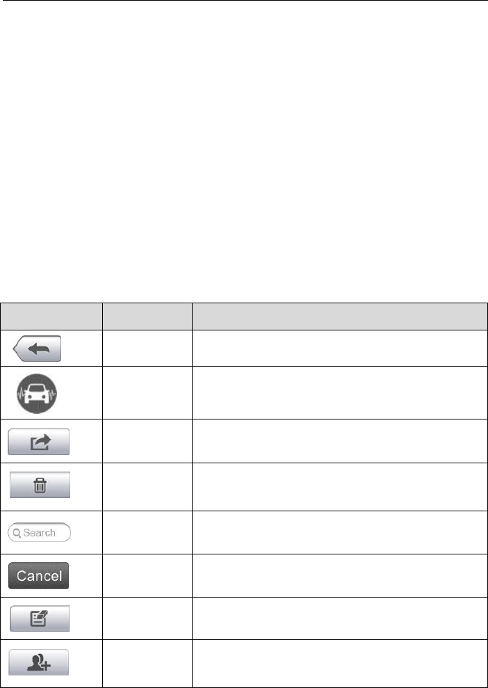
manipulated by the toolbar buttons, which are listed and described in the table below:
Table 7-1 Top Toolbar Buttons in Shop Manager
Button
Name
Description
Back
Returns to the previous screen.
Diagnostics
Touching this button directs you to the vehicle’s
Diagnostics screen to activate a direct test
session.
Enter Edit
Touching this button shows the editing toolbar to
print or delete the selected file.
Delete
Touching this button deletes the selected vehicle
record item from the list.
Search
Quickly locates the vehicle record by entering the
vehicle name or test path.
Cancel
Touching this button to cancel edit or file search.
Edit
Touching this button allows you to edit information
for the displayed file.
Add
Account
Touching this button to create a new customer
account file.
Shop Manager Operations Vehicle History
77
Button
Name
Description
History
Notes
Touching this button opens a note form, which
allows you to create audio record, attach picture or
video, or edit text notes, etc.
Vehicle
History
Touching this button opens the Vehicle History
screen which displays the correlated test vehicle
records.
Done
Complete editing and save the file.
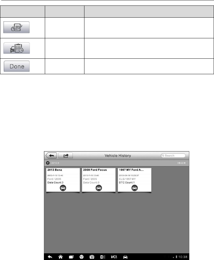
7.1 Vehicle History
This function stores records of test vehicle history, including vehicle
information and the retrieved DTCs from previous diagnostic sessions, and
displays all information in an easy-to-check table list, on which you can view
summarized details and manually input other information about the test
vehicle and diagnostic loggings, etc. The Vehicle History also provides direct
access to the previously tested vehicle and allows you to restart a diagnostic
session without the need to do vehicle identification again.
Figure 7-1 Sample Vehicle History Screen
1. Top Toolbar Buttons – navigates and makes various controls of the
application.
2. Main Section – displays all the vehicle history records information.
Shop Manager Operations Vehicle History
78
To activate a test session for the recorded vehicle
1. Tap the Shop Manager application on the MaxiSys Job Menu.
2. Select Vehicle History
3. Tap the Diagnostics button at the bottom of the thumbnail of a
vehicle record item. Or,
4. Select a vehicle record item by tapping the thumbnail.
5. A Historical Test record sheet displays, check the recorded
information of the recorded test vehicle, and tap the Diagnostics
button on the upper right corner.
6. The vehicle’s Diagnostics screen displays, now a new diagnostic
session is activated, see 4.6 Diagnosis on page 32 for detailed
instructions on vehicle diagnostic operations.
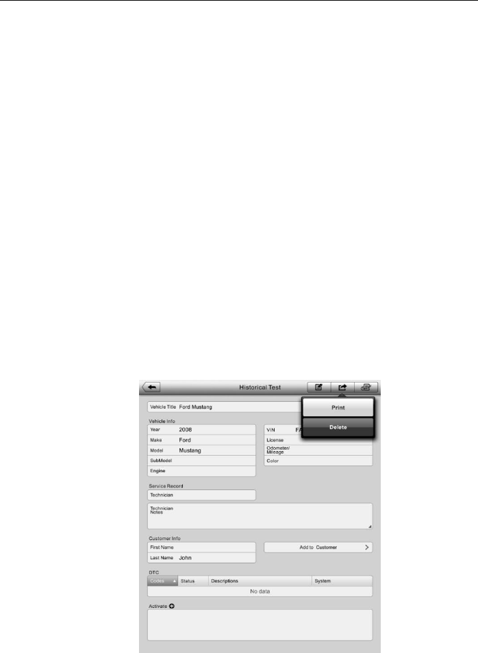
7.1.1 Historical Test Record
The Historical Test record sheet of the tested vehicle is a detailed data form,
which includes all general information of the vehicle such as vehicle year,
make and model, etc., and the diagnostic trouble codes retrieved from the
previous test sessions, as well as other service details which can be added
manually by the technician himself.
Figure 7-2 Sample Historical Test Record Sheet

Shop Manager Operations Workshop Information
79
To edit the Historical Test record sheet
1. Tap the Shop Manager application on the MaxiSys Job Menu.
2. Select Vehicle History.
3. Select the specific vehicle history record thumbnail from the main
section. The Historical Test record sheet displays.
4. Tap the Edit button to start editing.
5. Tap on each item to input the corresponding information or add
attaching files or images.
NOTE: The vehicle VIN number, or license and the customer information
account are correlated by default. Adding one of the information will
automatically associate the other item in the record sheet, provided that
the later one exists.
6. Tap Add to Customer to correlate the Historical Test record sheet to
an existing customer account, or add a new associating account to
be correlated with the test vehicle record. See 7.3 Customer
Manager on page 80 for more information.
7. Tap Done to save the updated record sheet, or tap Cancel to exit
without saving.
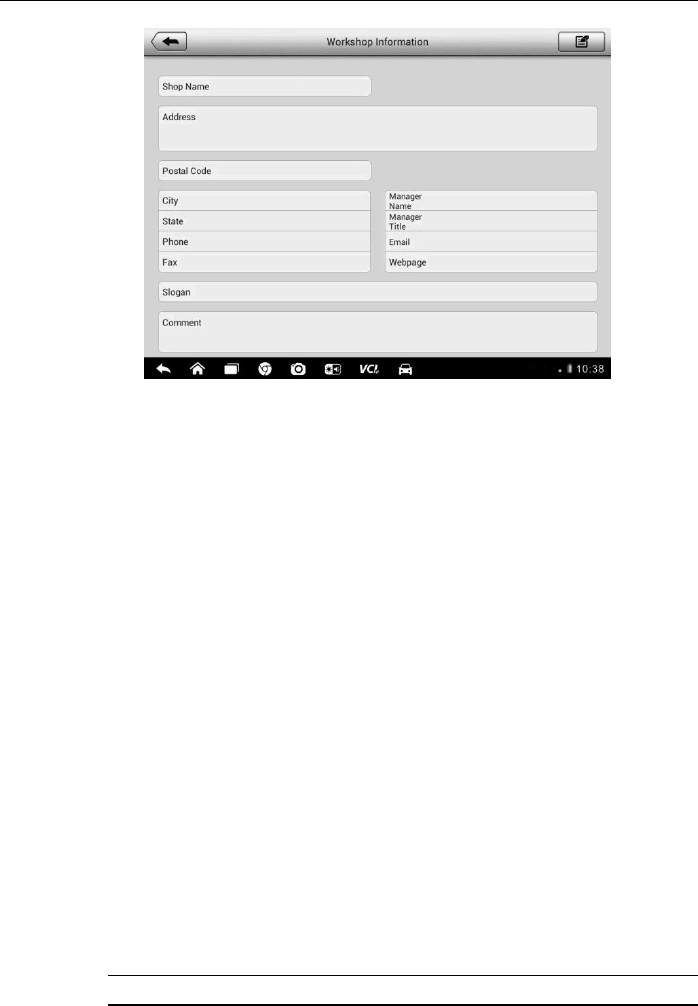
7.2 Workshop Information
The Workshop Information form allows you to edit, input and save the detailed
workshop information, such as shop name, address, phone number and other
remarks, which, when printing vehicle diagnostic reports and other associated
test file, will appear as the header of the printed documents.
Shop Manager Operations Customer Manager
80
Figure 7-3 Sample Workshop Information Sheet
To edit the Workshop Information sheet
1. Tap the Shop Manager application on the MaxiSys Job Menu.
2. Select Workshop Information.
3. Tap the Edit button on the top toolbar.
4. Tap on each field to input the appropriate information.
5. Tap Done to save the updated workshop information sheet, or tap
Cancel to exit without saving.
7.3 Customer Manager
The Customer Manager function allows you to create and edit customer
accounts. It helps you to save and organize all customer information accounts
that are correlated with the associated test vehicle history records, which is a
great support for the arrangement of daily workshop business.
To create a customer account
1. Tap the Shop Manager application on the MaxiSys Job Menu.
2. Select Customer Manager.
3. Tap the Add Account button. An empty information form displays,
tap each field to input the appropriate information.
NOTE: The items that must be filled are indicated as required fields.

Shop Manager Operations Customer Manager
81
4. Tap the □
+ photo frame beside the Name chart to add a photo. A
sub menu displays, select Take Photo to take a new photo for the
account, or select Choose Photo to choose from the existing files.
5. Some customers may have more than one vehicle for service; you
can always add new vehicle information to the account to be
correlated. Tap Add New Vehicle Information, and then fill in the
vehicle information. Tap the ○
x button to cancel adding.
6. Tap Done to save the account, or tap Cancel to exit without saving.
To edit a customer account
1. Tap the Shop Manager application on the MaxiSys Job Menu.
2. Select Customer Manager.
3. Select a customer account by tapping the corresponding name card.
A Customer Information sheet displays.
4. Tap the Edit button on the top toolbar to start editing.
5. Tap on the input field where needs to be altered or supplemented,
and enter updated information.
6. Tap Done to save the updated information, or tap Cancel to exit
without saving.
To delete a customer account
1. Tap the Shop Manager application on the MaxiSys Job Menu.
2. Select Customer Manager.
3. Select a customer account by tapping the corresponding name card.
A Customer Information sheet displays.
4. Tap the Edit button on the top toolbar to start editing.
5. Tap the Delete Customer Information button. A confirmation
message displays.
6. Tap OK to confirm the command, and the account is deleted. Tap
Cancel to cancel the request.
Shop Manager Operations Customer Manager
82
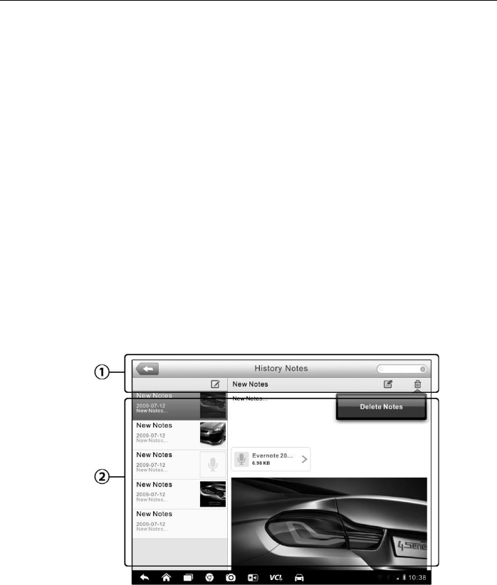
7.3.1 History Notes
The History Notes function allows you to add audio and video records, text
notes and photos, to keep multi-media work logs for the associated customer
account, which can be very helpful when dealing with repeat customers.
Keeping notes for each vehicle serviced for each customer will keep you
always on track and well organized in business.
To access History Notes
1. Tap the Shop Manager application on the MaxiSys Job Menu.
2. Select Customer Manager or Vehicle History.
3. Select a customer account by tapping the corresponding name card.
A Customer Information sheet displays (if Customer Manager is
selected). Or, select a vehicle history record item to open the
Historical Test record sheet (if Vehicle History is selected).
4. Tap the History Notes button on the top bar. Now the History Notes
screen displays.
Figure 7-4 Sample History Notes Screen
1. Functional Buttons – navigates and make various controls of the
function
2. Main Section – displays the note list on the left column and the detail
information of the selected note on the right column
Shop Manager Operations Customer Manager
83
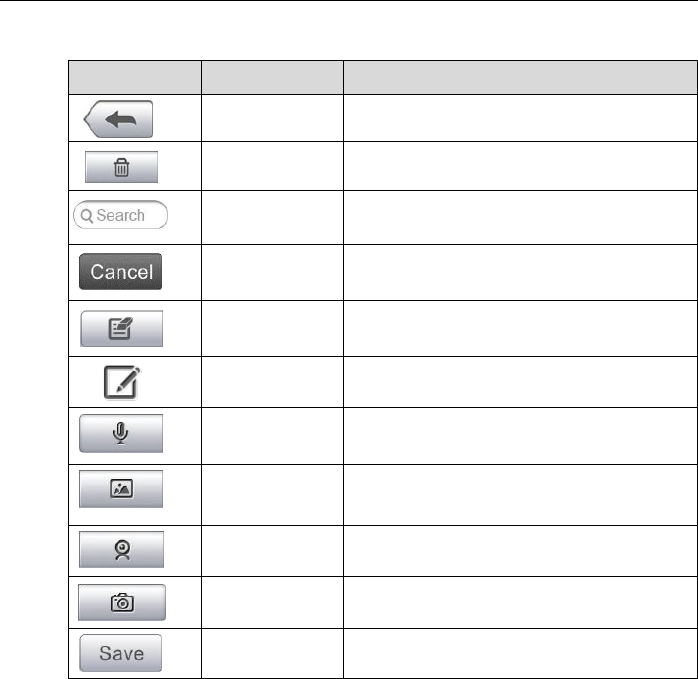
Table 7-2 Function Buttons in History Notes
Button
Name
Description
Back
Returns to the previous screen.
Delete
Touching this button deletes the selected
note.
Search
Quickly locates the required note by
entering the note title.
Cancel
Touching this button to cancel edit or file
search.
Edit
Touching this button opens an edit
window allowing you to edit notes and
attach files.
Add Notes
Touching this button to add new note in
History Notes.
Audio Record
Performs audio recording and creates
audio files.
Add Photos
Opens the image file for selection, and
adds the selected photos to History
Notes.
Take a Video
Records a video and adds the file to
History Notes.
Take a Photo
Takes photos and adds the files to History
Notes.
Save
Saves notes.
To add a note in History Notes
1. Access History Notes.
2. Tap the Add Notes button. An edit window displays.
3. Tap on the Title bar to input a note title.
4. Tap on the blank space below to edit a text note or remark.
5. Select a function button on the top to add files in any form you
choose.
6. Tap Save to save the note; tap Discard or Cancel to exit without
saving.
84
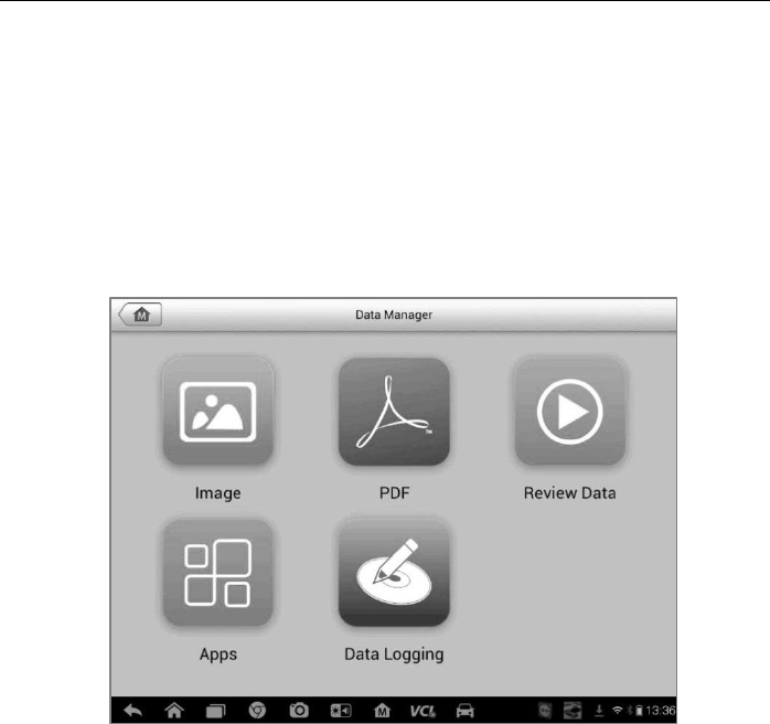
Chapter 8 Data Manager Operations
The Data Manager application is used to store, print, and review the saved files. Most
operations are controlled through the toolbar.
Selecting the Data Manager application opens the file system menu. Different file types
are sorted separately under different options, there are six types of information files to
be viewed or played back.
Figure 8-1 Sample Data Manager Main Screen
8.1 Operations
Data Manager Operations are based on toolbar controls. Details are explained
in the following sections.
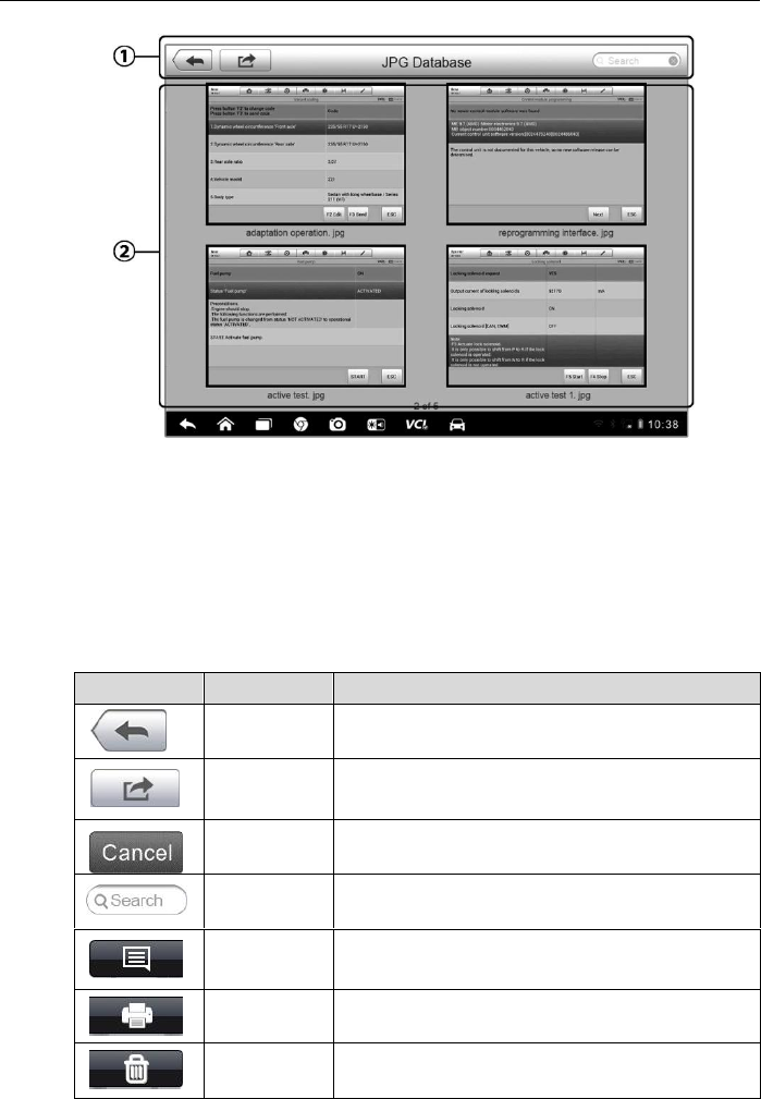
8.1.1 Image Files
The Image section is a JPG database containing all captured screenshot
images.
Data Manager Operations Operations
85
Figure 8-2 Sample Image Database Screen
1. Toolbar Buttons – used to edit, print and delete the image files. See
Table 8-1 Toolbar Buttons in JPG Database on page 85 for detailed
information.
2. Main Section – displays the stored images.
Table 8-1 Toolbar Buttons in JPG Database
Button
Name
Description
Back
Returns to the previous screen.
Enter Edit
Tapping this button shows the editing toolbar
to print, delete or view image information.
Cancel
Tapping this button close the editing toolbar or
cancels file search.
Search
Quickly locates the image file by entering the
vehicle name, test path, file name or file info.
Info
Tapping this button opens a window displaying
the details of the image.
Print
Tapping this button prints the selected image.
Delete
Tapping this button deletes the selected
image.

Data Manager Operations Operations
86
To edit image information
1. Select Data Manager application from the MaxiSys Job Menu.
2. Select Image to access the JPG database.
3. Select an image to display it in full screen.
4. Tapping the screen once displays the editing toolbar.
5. Tap the Info button to open a window displaying the image
information.
6. Tap the Edit button on the top right corner of the window. The editing
screen displays.
7. Edit the image information by entering the new file name, and file
information.
8. Tap Done to save the information and exit, or tap Cancel to exit
without saving.
To delete selected images
1. Select Data Manager application from the MaxiSys Job Menu.
2. Select Image to access the JPG database.
3. Tap the Enter Edit button to display the editing toolbar.
4. Select the images that need to be deleted by tapping the thumbnail
images, the selected thumbnail displays a tick icon at the bottom
right corner.
5. Tap the Delete button, and then Delete Selected, then the selected
images will be deleted.
8.1.2 PDF Files
The PDF section stores and displays all PDF files of saved data. After entering
the PDF database, select a PDF file to view the stored information.
This section uses the standard Adobe Reader application for file viewing and
editing, please refer to the associated Adobe Reader manual for more detailed
instructions.
Data Manager Operations Operations
87
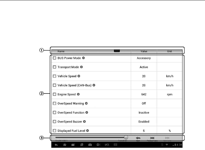
8.1.3 Review Data
The Review Data section allows you to playback the recorded data frames of
live data streams.
On the Review Data main screen, select a record file to playback.
Figure 8-3 Sample Data Playback Screen
1. Drop-down Toolbar – tap the button at the top center of the screen to
open the Drop-down Toolbar
2. Main Section – displays the recorded data frames
3. Navigation Toolbar – allows you to manipulate data playback
Use the Navigation Toolbar buttons to playback the record data from frame to
frame.
Tap Back to exit data playback.
8.1.4 Apps Manager
This section allows you to manage the firmware applications installed on the
MaxiSys Diagnostics System. Selecting this section opens a managing screen,
on which you can check all the available vehicle diagnostic applications.
Select the vehicle firmware you want to delete by tapping on the car brand
icon, the selected item will display a blue tick at the upper right corner. Tap the
Delete button on the top bar to delete the firmware from the system database.


89
Chapter 9 Settings Operations
Selecting Settings application opens a setup interface, on which you can adjust default
setting and view information about the MaxiSys system. There are seven options
available for the MaxiSys system settings:
Unit
Language
Printing Setting
Notification Center
About
System Settings
9.1 Operations
This section describes the operation procedures for the settings.
9.1.1 Unit
This option allows you to adjust the measurement unit for the diagnostic
system.
To adjust the unit setting
1. Tap the Settings application on the MaxiSys Job Menu.
2. Tap the Unit option on the left column.
3. Select the required measurement unit, Metric or English. A tick icon
will display to the right of the selected unit.
4. Tap the Home button on the top left corner to return to the MaxiSys
Job Menu. Or select another setting option for the system setup.
9.1.2 Language
This option allows you to adjust the display language for the MaxiSys system.

Settings Operations Operations
90
To adjust the language setting
1. Tap the Settings application on the MaxiSys Job Menu.
2. Tap the Language option on the left column.
3. Select the required language. A tick icon will display to the right of
the selected language.
4. Tap the Home button on the top left corner to return to the MaxiSys
Job Menu. Or select another setting option for the system setup.
9.1.3 Printing Setting
This option allows you to print any data or information anywhere and anytime
via Wi-Fi connection. For more information about printing, see 3.3.1 Printing
Operation on page 17.
To setup the printer connection
1. Tap the Settings application on the MaxiSys Job Menu.
2. Tap the Printing Setting option on the left column.
3. Tap the Print via Network item to activate the printing function,
which enables the device to send files to the printer through the PC
via Wi-Fi connection.
4. Tap the Home button on the top left corner to return to the MaxiSys
Job Menu. Or select another setting option for the system setup.
9.1.4 Notification Center
This option allows you to turn the Notification Center function on or off. The
Notification Center function configures the MaxiSys tablet to receive regular
on-line messages from the server for system update notifications or other
service information via the Internet. It is highly recommended to keep this
function on all the time, so you won’t miss out any new update for MaxiSys or
event from Autel. Internet access is required for receiving on-line messages.
To enable the Notification Center function
1. Tap the Settings application on the MaxiSys Job Menu.

Settings Operations Operations
91
2. Tap the Notification Center option on the left column.
3. Tap the ON/OFF button to enable or disable the Notifications
function. If the function is enabled the button turns blue, or if
disabled the button turns gray.
4. Tap the Home button on the top left corner to return to the MaxiSys
Job Menu. Or select another setting option for the system setup.
When the Notification Center function is turned on, and new messages are
received by the MaxiSys device, a notification message displays on the
MaxiSys Job Menu. Press on the message bar and drag it down, and the
received messages are shown in the list, slide the list up or down to view all if
the message list covers more than one screen.
Tapping a specific message launches the corresponding application. For
example, if you tap on an Update notification message, the Update application
will be launched.
9.1.5 About
The About option provides information of the MaxiSys diagnostic device
regarding the product name, version, hardware, and serial number, etc.
To check the MaxiSys product information in About
1. Tap the Settings application on the MaxiSys Job Menu.
2. Tap the About option on the left column. The product information
screen displays on the right.
3. Tap the Home button on the top left corner to return to the MaxiSys
Job Menu, or select another setting option for the system setup,
after viewing.
9.1.6 System Settings
This option provides you a direct access to the Android background system
setting interface, on which you can adjust various system settings for the
Android system platform, regarding wireless and networks settings, various
device settings such as sound and display, as well as system security settings,
and check the associated information about the Android system, etc.
To enable the App Switcher function
1. Tap the Settings application on the MaxiSys Job Menu.
2. Tap the System settings option on the left column.

Settings Operations Operations
92
3. Tap the App Switcher option on the left column.
4. Mark the checkbox beside “Always show the App Switcher” on the
right side of the screen, then the App Switcher icon shows.
Short pressing the App Switcher icon opens a control panel:
Tapping a specific app shortcut button enables you to switch directly to
the selected application screen.
Long pressing a specific app shortcut button displays the app menu, on
which you can select and change the app shortcut.
Pressing and dragging the App Switcher icon around allows you to
change the icon position alongside the edge of the screen.
You may refer to Android documentation for additional information about
Android system settings.
93
Chapter 10 Update Operations
The Update application allows you to download the latest released software. The
updates can improve the MaxiSys applications’ capabilities, typically by adding new
tests, new models, or enhanced applications to the database.
The Display Tablet automatically searches for available updates for all of the MaxiSys
software when it is connected to the internet. Any updates that are found can be
downloaded and installed on the device. This section describes installing an update to
the MaxiSys System. A notification message displays if an update is available when the
Notifications Center function is enabled in the Settings application (See 9.1.4
Notification Center page 90 for details).
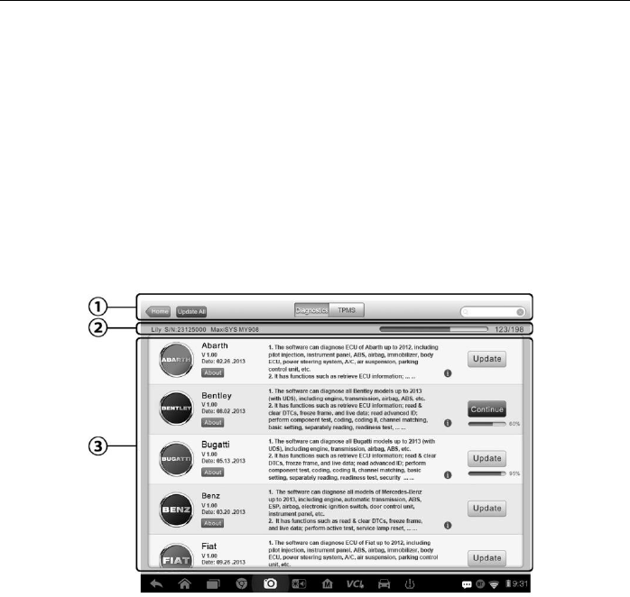
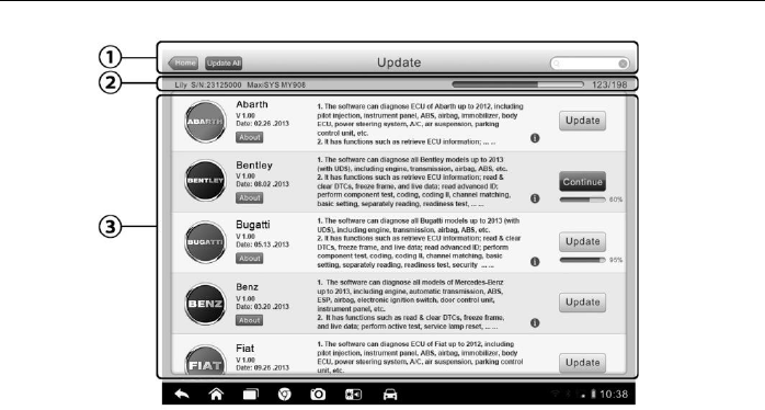
Figure 10-1 Sample Update Screen – for MaxiSys MS906TS
Update Operations Operations
94
Figure 10-2 Sample Update Screen – for MaxiSys MS906BT
1. Navigation and Controls
Home Button – returns to the MaxiSys Job Menu
Update All – updates all available updates
Diagnostics Tab – displays all available vehicle diagnostic software
TPMS Tab - displays all available TPMS service software for vehicles (for
MS906TS only)
Search Bar – search specific update item by inputting the file name, for
example: a vehicle make
2. Status Bar
Left Side – displays the MaxiSys device model information and serial number
Right Side – displays an update progress bar indicating the completion status
3. Main Section
Left Column – displays vehicle logos and update software version information;
tap the About button displays a function list in PDF showing more details
about the software
Middle Column – displays a brief introduction about the new changes to the
software operation or capabilities. Tap ○
i button to open an information
screen to view more details, and tap the dim area around to close the window.

Update Operations Operations
95
Right Column – according to the operation status of each software item, the
button displays differently.
a) Tap Update to update the selected item.
b) Tap Pause to suspend the updating procedure.
c) Tap Continue to go on updating the suspended update.
To update the diagnostic software and TPMS service software
1. Make sure the Display Tablet is connected to a power source with stable
access to the internet.
2. Tap the Update application button from the MaxiSys Job Menu; or tap the
update notification message when received one; or tap the Update icon on
Vehicle Menu in Diagnostics application. The Update application screen
displays.
3. Check all available updates:
If you decide to update all the items of diagnostic software, select
Diagnostics Tab and then tap the Update All button; if you want to
update all items of TPMS service software, select TPMS Tab and then
tap the Update All button.
If you only want to update one or some of the item(s), tap the Update
button on the right column of the specific item(s).
4. Tap the Pause button to suspend the updating process. When you tap
Continue to renew the update, the updating process will resume from the
break point.
5. When the updating process is completed, the firmware will be installed
automatically. The previous version will be replaced.
96
Chapter 11 VCI Manager Operations
This application allows you to pair up the Display Tablet with the VCI device, check the
communication status, and update the VCI software and TPMS service firmware.
Figure 11-1 Sample VCI Manager Screen
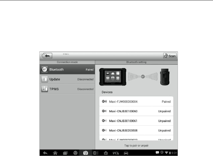
1. Connection Mode – there are three connection modes available for selection.
The connection state is displayed alongside.
BT Paring – when paired to a wireless device, the connection state displays
as Paired; otherwise it displays as Unpaired.
Update (for VCI software only) – Update VCI software via internet through
the MaxiSys tablet networking using USB connection.
TPMS Module Update – Update TPMS firmware of the Display Tablet via the
internet through the tablet networking (for MS906TS)
2. BT Setting
The BT Setting screen displays the type and a partial serial number for all of the
devices available for pairing. Tap a required device to start pairing. The BT status
icon displayed to the left of the device name indicates the received signal strength.
11.1 BT Pairing
The VCI device needs to be connected to a vehicle, so that it is powered up

VCI Manager Operations BT Pairing
97
during the synchronization procedure. Make sure the Display Tablet has
sufficient battery level or is connected to an AC/DC power supply.
To pair the VCI device with the Display Tablet
1. Power on the Display Tablet.
2. Insert the 16-pin vehicle data connector of the MaxiVCI V100 to the
vehicle data link connector (DLC).
3. Tap the VCI Manager application on the MaxiSys Job Menu of the
Display Tablet.
4. Select BT from the connection mode list.
5. Tap the Scan button at the top right corner. Now the device starts
searching for available pairing units.
6. The device name may display as Maxi suffixed with a serial number.
Select the required device for pairing.
7. When paring is successfully done, the connection status displayed
to the right of the device name is shown as Paired.
8. Wait a few seconds, and the VCI button on the system Navigation
bar at the bottom of the screen shall display a green tick icon,
indicating the Display Tablet is connected to the VCI device.
9. Tap the paired device again to unpair it.
10. Tap the Home button on the top left to return to the MaxiSys Job
Menu.
NOTE: A VCI device can be paired to only one Display Tablet each time,
and once it’s been paired, the device will not be discoverable for any
other unit.
11.2 Update
Before update the VCI software, please make sure the Display Tablet network
connection is stable.

VCI Manager Operations TPMS Module Update
98
To update the VCI device software
1. Power on the Display Tablet.
2. Connect the VCI device to Display Tablet via USB.
3. Tap the VCI Manager application on the MaxiSys Job Menu of the
Display Tablet.
4. Select Update from the connection mode list.
5. The current version and the latest version of the VCI software will be
displayed after a few seconds, click Update Now to update the VCI
software if available.
11.3 TPMS Module Update
Before update the TPMS module in the Display Tablet, please make sure the
Display Tablet network connection is stable.
NOTE: This option is available for MaxiSys MS906TS only.
To update the TPMS Module
1. Power on the Display Tablet.
2. Tap the VCI Manager application on the MaxiSys Job Menu of the
Display Tablet.
3. Select TPMS from the connection mode list.
4. The current version and the latest version of the TPMS firmware will
be displayed after a few seconds, click Update Now to update the
TPMS firmware if available.

99
Chapter 12 Support Operations
This application launches the Support platform which synchronizes Autel’s on-line
service base station with the Display Tablet. In order to synchronize the device to your
on-line account, you need to register the product through the Internet when you use it
for the first time. The Support application is connected to Autel’s service channel and
on-line communities which provides the quickest way for problem solutions, allowing
you to submit complaints or sent help requests to obtain direct services and supports.
12.1 Product Registration
In order to get access to the Support platform and obtain update and other
services from Autel, you are required to register the MaxiSys Diagnostic
Device the first time you use it.
To register the diagnostic device
1. Visit the website: http://pro.autel.com.
2. On the Sign In page, input your account ID and other information to
log in, if you already have an account.
3. If you are a new member to Autel and do not have an account yet,
click the Create Autel ID button on the left side.
4. Enter the required information in the input fields, read through
Autel’s Terms and Conditions and tick on Agree, and then click
Create Autel ID at the bottom to continue.
5. The online system will automatically send a confirmation email to the
registered email address. Validate your account by clicking the link
provided through the mail. A product registration screen opens.
6. Find out the device’s serial number and password from the About
section of the Settings application on the Display Tablet.
7. Select the product model of your device, enter the product serial
number and password on the Product Registration screen, and click
Submit to complete the registration procedure.
Support Operations Support Screen Layout
100
12.2 Support Screen Layout
The Support application interface is navigated by 4 simple buttons on the top
navigation bar, operation of each is described below in turn from left to right:
Home Button – returns to the MaxiSys Job Menu.
Back – returns to the previous screen, each press takes you back one
step.
Forward – each press moves forward one screen until you’ve reached
the last screen visited.
Refresh – reload and update the screen.
Figure 12-1 Sample Support Application Screen
The main section of the Support screen is divided into two sections. The
narrow column on the left is the main menu; selecting one subject from the
main menu displays the corresponding functional interface on the right.

Support Operations My Account
101
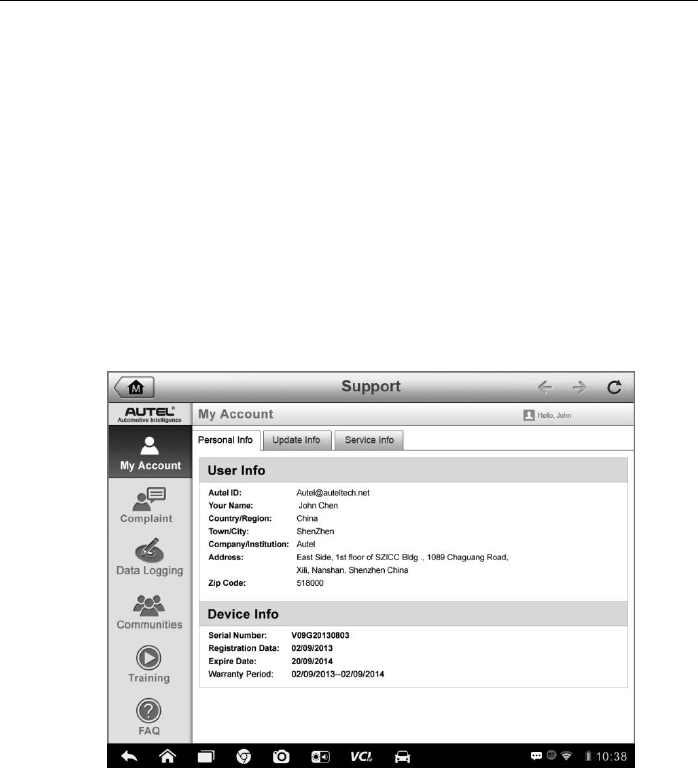
12.3 My Account
The My Account screen displays the comprehensive information of the user
and the product, which is synchronized with the on-line registered account,
including User Info, Device Info, Update Info and Service Info.
Personal Info
The User Info and Device Info are both included under the Personal Info
section.
User Info - displays detailed information of your registered on-line Autel
account, such as your Autel ID, Name, Address and other contact
information, etc.
Device Info – displays the registered product information, including the
Serial Number, Registration Date, Expire Date, and Warranty Period.
Update Info
The Update Info section displays a detailed record list of the product’s
software update history, including the product serial number, software version
or name, and the update time.
Service Info
The Service Info section displays a detailed record list of the device’s service
history information. Every time the device has been sent back to Autel for
repair, the device’s serial number and the detailed repair information, such as
the fault type, changed components, or system reinstallation, etc., will be
recorded and updated to the associated online product account, which will be
synchronized to the Service Info section.
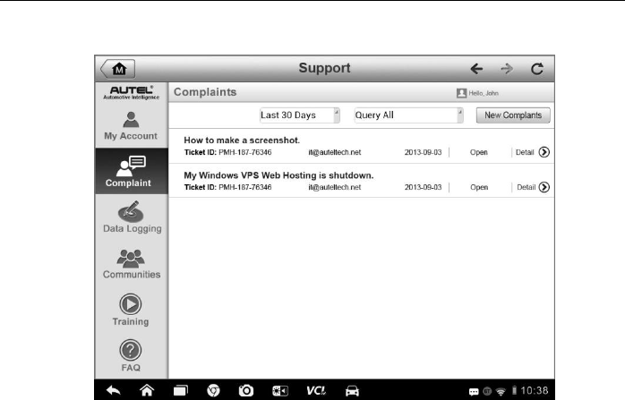
12.4 User Complaint
The User Complaint screen allows you to establish a new complaint case, as
well as to view historical complaint records.
Support Operations User Complaint
102
Screen Layout
Figure 12-2 Sample Complaint Screen
The User Complaint screen consists of two parts.
1. Option Bar
Period Filter – displays only the complaint records within the
defined period on the list
Status Filter – displays the corresponding complaint records
according to the selected case status
New Complaint Button – starts a new complaint case.
2. Complaint List
The complaint list normally displays all the complaint records of all time
and all status by default. The summary information for each complaint
item includes the Subject Name, Ticket ID, User’s Account ID, Date, and
the Case Status.
There are four kinds of the case status:
Open – indicates the complaint case has been started but not
processed yet
Suspended – indicates the complaint case is being processed

Support Operations User Complaint
103
Waiting Customer Reply – indicates the complaint has been
replied by the service personnel, and requires feedback from the
customer
Closed – indicates the complaint case has been processed, solved,
and ended
To view the detailed complaint session, tap the ○
> button on the
right side of the case item.
To establish a new complaint session
1. Register the product online.
2. Tap the Support application on the MaxiSys Job Menu. The device
information is automatically synchronized with the online account.
3. Tap Complaint on the Main Menu.
4. Tap the New Complaint button at the upper right corner. A
selection menu with a category of service channels displays.
5. Select your target service channel and click Next to continue. A
standard complaint form displays, on which you are allowed to
enter detailed information, such as personal information, vehicle
information, and device information, you can also attach image or
PDF files with the form.
6. Enter in each input field the appropriate information, in order to
settle the complaint more efficiently, it is recommended to fill out the
complaint form as detailed as possible.
7. Select the required processing time on the last section according to
the urgency of the case.
8. Tap Submit to send the completed form to Autel’s online service
center, or tap Reset to refill it. The submitted complaints will be
carefully read and handled by the service personnel, and the
respond speed may depend on the processing time you’ve
required.
To make a reply in a complaint session
1. Register the product online.
2. Tap the Support application on the MaxiSys Job Menu. The device
information is automatically synchronized with the online account.
Support Operations Data Logging
104
3. Tap Complaint on the Main Menu.
4. Select an existing complaint case item on the record list by tapping
the ○
> button on its right side. The screen displays the complaint
session details.
5. Tap the Post Reply button on the upper right side after viewing, to
make a reply. An edit screen displays.
6. Input the content in the input field, and if necessary, upload an
attaching file.
7. Tap Submit to post the reply.
8. Tap the States selection drop-down menu to reset a case state.
9. Tap the Update button to commit the newest update.
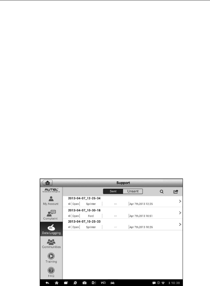
12.5 Data Logging
The Data Logging section keeps records of all sent or unsent (saved) data
loggings on the diagnostic system. The support personnel receive and
process the submitted reports through the Support platform, and send back
problem solutions within 48 hours to the corresponding Data Logging session,
on which you are also allowed to have a direct conversation with the support
personnel.
Figure 12-3 Sample Data Logging Screen
Support Operations Communities
105
To make a reply in a Data Logging session
1. Tap on the Sent tag to view a list of submitted data loggings.
2. Select a specific item to view the latest update of the processing
progress.
3. Tap on the input field at the bottom of the screen, and enter the texts.
Or tap the Audio button to record a voice message, or camera
button to take a picture.
4. Tap Send to deliver your message to the technical center.
12.6 Communities
The Communities section launches and synchronizes with the Technical
Forums on Autel’s official website www.autel.com, where you are allowed to
discuss technical topics or share information with, as well as ask for technical
advices or offer technical supports to all other members in Autel’s online
support communities.
Figure 12-4 Sample Communities Home Screen
To start a discussion
1. Tap Start a discussion on the Communities Home screen. A list of
the major forums is displayed.

Support Operations Communities
106
2. Select a desired group according to the subject you are about to
discuss. For example, if you are going to ask a question about the
MaxiSys tablet, tap MaxiSys to start a discussion.
3. Enter your topic and the discussion content in the appropriate input
field.
4. Select a category or edit tags for the discussed post. This will help
other members with similar interest to find your post.
5. Tap OK to submit the post.
To join and reply to a discussion post
1. Select a forum group that you are interested in, whether by the
product or the features, on the Communities Home screen. A list of
the latest posts is displayed.
2. Select a specific category on the Categories menu to better pinpoint
the topics you are most interested with.
3. Tap the ○
> button on the right side of the topic item to view the
discussion. The posts contents are displayed.
4. Browse through all the posts by sliding the screen up and down. Tap
Go to original post when reaching the end of the discussion to
return to the first post.
5. Tap Reply to reply a specific post, or tap Reply to original post to
join and continue the whole discussion.
6. Enter your comment in the input field, and tap OK to submit your
post.
User Profile
The User Profile section allows you to set personal Avatar, check your
member status and other information, as well as to review your personal posts
in the communities.
Tap the Avatar image on the Communities screen to open the User Profile.
Support Operations Training Channels
107
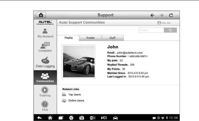
Figure 12-5 Sample User Profile Screen
Profile – displays the user’s personal information and member status.
The Related links allow you to check the Top Users (ranked according
to their points and levels) in the communities, as well as to find out other
online users.
Avatar – allows you to select an image to set as your personal Avatar to
be displayed in the communities.
Stuff – displays all the discussions you’ve posted at various forums in a
list.
12.7 Training Channels
The Training section provides quick links to Autel’s online video accounts.
Select a video channel by the language to see all the available online tutorial
videos from Autel for various technical supports, such as product usage
techniques and vehicle diagnostics practice, etc., may be available for your
interests.

Support Operations FAQ Database
108
12.8 FAQ Database
The FAQ section provides you comprehensive and abundant references for all
kinds of questions frequently asked and answered about the use of Autel’s
online member account, and shopping and payment procedures.
Account – displays questions and answers about the use of Autel’s
online user account.
Shopping & Payment – displays questions and answers about online
product purchase and payment methods or procedures.
109
Chapter 13 Training Operations
The Training application provides and allows you to play various tutorial videos stored
on the device. The stored training materials mainly consists of product usage tutorials
and vehicle diagnostic training videos, all produced by top-notch technicians and
product experts. The application also allows you to download or watch more associated
videos online, by providing quick links to Autel’s online video database.
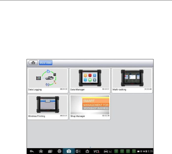
Figure 13-1 Sample Training Application Screen
1. Navigation Buttons – allows you to navigate the application interface.
Home Button – returns to the MaxiSys Job Menu
More Video Button– displays all available video files with stable network
connection
2. Main Section – displays the available video files for watching
To play a video
1. Tap the Training application on the MaxiSys Job Menu. The Training
application screen displays.

Training Operations Operations
110
2. Select a video file from the main section.
3. Select a Player from the popup window if necessary. Now you can watch the
video, it is played in full screen mode.
111
Chapter 14 Remote Desk Operations
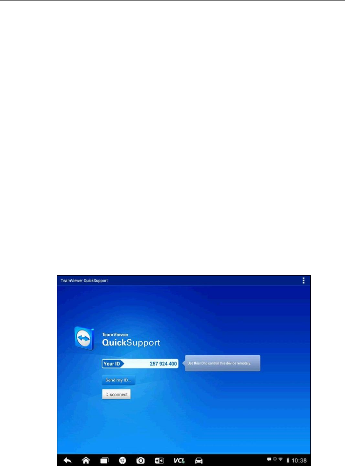
The Remote Desk application launches the TeamViewer Quick Support program, which
is a simple, fast and secure remote control interface. You can use the application to
receive ad-hoc remote support from Autel’s support center, colleagues, or friends, by
allowing them to control your MaxiSys tablet on their PC via the TeamViewer software.
14.1 Operations
If you think of a TeamViewer connection as a phone call, the TeamViewer ID
would be the phone number under which all TeamViewer Clients can be
reached separately. Computers and mobile devices that run TeamViewer are
identified by a globally unique ID. The first time the Remote Desk application
is started, this ID is generated automatically based on the hardware
characteristics and will not change later on.
Make sure the Display Tablet is connected to the Internet before launching the
Remote Desk application, so that the Display Tablet is accessible to receive
remote support from the third party.
Figure 14-1 Sample Remote Desk Screen

Remote Desk Operations Operations
112
To receive remote support from a partner
1. Power on the Display Tablet.
2. Tap the Remote Desk application on the MaxiSys Job Menu. The
TeamViewer interface displays and the device ID is generated and
shown.
3. Your partner must install the Remote Control software to his/her
computer by downloading the TeamViewer full version program
online (http://www.teamviewer.com), and then start the software on
his/her computer at the same time, in order to provide support and
take control of the Display Tablet remotely.
4. Provide your ID to the partner, and wait for him/her to send you a
remote control request.
5. A popup displays to ask for your confirmation to allow remote control
on your device.
6. Tap Allow to accept, or tap Deny to reject.
Refer to the associated TeamViewer documents for additional information.
113
Chapter 15 Quick Link Operations
The Quick Link application provides you with convenient access to Autel’s official
website and many other well-known sites in automotive service, which offers you
abundant information and resources, such as technical help, knowledge base, forums,
training, and expertise consultations, etc.
Figure 15-1 Sample Quick Link Screen
To open a quick link
1. Tap the Quick Link application on the MaxiSys Job Menu. The Quick Link
application screen displays.
2. Select a website thumbnail from the main section. The Chrome browser is
launched and the selected website is opened.
3. Now you can start exploring the website!
114
Chapter 16 Oscilloscope Operations
The Oscilloscope application configures the MaxiSys Diagnostic Device to operate as
an automotive oscilloscope when work in combination with the MaxiScope module.
This function provides all the features needed for performing electrical and electronic
circuit tests as well as monitoring signal activities on any modern vehicles, which shows
you what is really going on with a vehicle’s electrical system.
16.1 Safety Information
Follow these instructions to reduce the risk of injury from electric shock and prevent
equipment damage.
A. Maximum input ranges
Observe all terminal ratings and warnings marked on the product.
DANGER:
To prevent electric shock, operate within the safe input range for the scope,
refer to 16.1 Safety Information on page 114.
To prevent electric shock, take all necessary safety precautions when
working on equipment where voltages above the specified input range may
be present. Contact with voltages outside of the specified measuring range
presents a risk of electric shock.
To prevent injury or death, the oscilloscope must not be directly connected to
the mains (line power). To measure mains voltages, use a differential
isolating probe specifically rated for mains use.
WARNING:
Operation outside of the safe input range is likely to cause permanent
damage to the oscilloscope and other connected equipment.
B. Grounding
DANGER:
The scope’s ground connection through the USB cable is for measurement
purposes only. The oscilloscope does not have a protective safety ground.
Do not connect the ground input (chassis) to any electrical power source. To
prevent personal injury or death, use a voltmeter to check that there is no
significant AC or DC voltage between the oscilloscope ground and the point
to which you intend to connect it.
Oscilloscope Operations Safety Information
115
WARNING:
Applying a voltage to the ground input is likely to cause permanent damage
to the oscilloscope, the attached computer, and other equipment.
To prevent measurement errors caused by poor grounding, always use the
high-quality USB cable supplied with the oscilloscope.
C. External connections
DANGER:
To prevent injury or death, use only the power cord and adaptor supplied with
the product.
D. Environment
DANGER:
To prevent injury or death, do not use in wet or damp conditions, or around
explosive gas or vapor.
WARNING:
To prevent damage, always use and store your oscilloscope in appropriate
environments. For detailed information on temperature and humidity
specifications for both the storage and usage of the oscilloscope, see 16.1
Safety Information on page 114.
E. Product Maintenance
The product contains no user-serviceable parts. Repair, servicing and calibration
require specialized test equipment and must only be performed by Autel Tech
Support or an approved service provider.
DANGER:
To prevent injury or death, do not use the product if it appears to be damaged
in any way, and stop use immediately if you are concerned by any abnormal
operations.
WARNING:
Do not tamper with or disassemble the oscilloscope, connectors or
accessories. Internal damage will affect performance.
Do not block any of the instrument’s air vents as overheating will cause
damage to the oscilloscope.
When cleaning the oscilloscope, use wet soft cloth with mild detergent in
water. Do not allow water to enter the oscilloscope casing, as this will cause
damage to the electronics inside.

Oscilloscope Operations Glossary
116
16.2 Glossary
AC/DC Control
Each channel can be set to either AC coupling or DC coupling. With DC coupling, the
voltage displayed onscreen is equal to the true voltage of the signal with respect to
ground. With AC coupling, any DC component of the signal is filtered out, leaving only
the variations in the signal for the AC component.
Aliasing
When the signal frequency gets higher than half the scope’s maximum sampling rate
and exceeds the limit, a distorted waveform appears. This distortion is called aliasing.
Analog Bandwidth
All oscilloscopes have an upper limit to the range of frequencies at which they can
measure accurately. The analog bandwidth of an oscilloscope is defined as the
frequency at which a displayed sine wave has half the power of the input sine wave
(about 71% of the amplitude).
Block Mode
A sampling mode in which the computer prompts the oscilloscope to collect a block of
data into its internal memory before stopping the oscilloscope and transferring the
whole block into computer memory. This mode of operation is effective when the input
signal being sampled is high frequency.
Buffer Size/Cache Size
This term indicates the size of the oscilloscope’s buffer memory. The buffer memory is
used by the oscilloscope to temporarily store data. This helps to compensate for the
differences in data transfer rate from one device to another.
Sampling Rate
This term is used to define the number of samples per second captured by the
oscilloscope. The faster the sampling rate of the scope, the more frequently it
measures the signal voltage, and so the more detailed will be the trace that appears on
the scope screen.
Streaming Mode
This term indicates a sampling mode in which the oscilloscope samples data and
returns it to the computer in an unbroken stream. This mode of operation is effective
when the input signal being sampled is at low frequency.
Oscilloscope Operations Glossary
117
Time Base
The time base controls the time interval across the scope display.
Voltage Range
The voltage range is the range between the maximum and minimum voltages that can
be accurately captured by the oscilloscope.
Sinusoidal Waveform
This term describes the waveform characteristics typically found in circuits with large
inductance and capacitance, and often referred to as an AC signal. The waveform
alternates either side of 0 volts or may rise and fall creating a regular sinusoidal shape:
Figure 16-1 Sample Sinusoidal Waveform
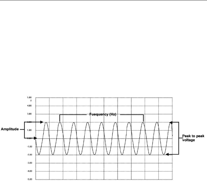
Amplitude
This term indicates the maximum voltage generated from the zero volts line of the
oscilloscope.
Frequency
This term describes the number of signal occurrences per second. Frequency is
measured in Hz (hertz).
Square Waveform
This term describes the waveform characteristics normally generated by signals
switching between clearly defined voltage levels, such as a Hal effect sensor signal
may create by switching a voltage to ground. A typical digital square waveform is shown
below:
Oscilloscope Operations MaxiScope Module
118
Figure 16-2 Sample Square Waveform
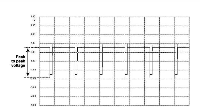
Peak to peak voltage
This term indicates the difference in voltage between the minimum and maximum
voltages occurring in the waveform.
16.3 MaxiScope Module
The MaxiScope Automotive Oscilloscope tool kit is optional and available for
purchase along with the MaxiSys package. There are 2 versions (basic and
advanced versions) available.
The MaxiScope tool kit comes standard with:
MaxiScope Module
CD with user manual and PC software
USB Cable
Other probe accessories
Oscilloscope Operations MaxiScope Module
119
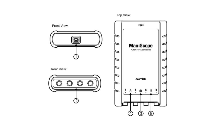
Figure 16-3 Front, Rear, and Top View
1. USB Port Connector
2. Input Channel A/B/C/D
3. LED Indicator Light – lights up when powered on, blinks when
communicating, and shimmers when error occurs
4. Warning Triangle – indicates potential safety hazard that exists on the
indicated connections, and appropriate precautions should be taken.
Make sure you read through the Safety Information on page 114 before
using.
5. Equipotential Symbol – indicates the outer shells of the indicated BNC
connectors are all at the same potential. Therefore, necessary
precautions should be taken to avoid applying a potential through the
return connections of the indicated BNC terminals, as this may result in a
large current flow, causing damage to the product and the connected
equipment.
Power Source
The MaxiScope MP408 Scope Module is powered directly by the USB port of
the connected PC, no batteries or power leads are required, making it suitable
for use both for workshop-based and mobile automotive diagnostics.

Oscilloscope Operations MaxiScope Module
120
Technical Specifications
Main Features
Description
Vertical resolution
12 bits
Channels
4
Bandwidth
20MHz
Accuracy
Voltage: 1%; Time: 50ppm
Sensitivity
10mV/div to 20V/div
Input Ranges (full scale)
±
50mV to
±
100V in 11 ranges
Input Impedance
1MΩ in parallel with 22pF
Input Type
Single-ended, BNC connector
Input Coupling
Software selectable AC/DC
Overload Protection
±
200V on single input
Maximum Sampling Rate
(Single Shot)
1 or 2 channels in use
3 or 4 channels in use
80MS/s*
20MS/s
Buffer Memory
32M samples shared among active channels
Waveform Buffer
Up to 1000 waveforms
Timebase Ranges
100ns/div to 1000s/div
Advanced Features
Math channels, Measurements
Triggers
Description
Source
Any input channel
Basic Triggers
Auto, Normal, Single, None
Advanced Triggers
Rising edge, Falling edge
Environmental
Description
Operating Temperature Range
Storage Temperature Range
Storage Humidity Range
0 to 50°C (15 to 40°C for quoted accuracy)
-20
to +60°C
5 to 95%RH, Non-condensing
Physical Characteristics
Description
Dimensions (Protection rubber
case include
d
)
190X115X38mm
Weight
<0.5kg
Oscilloscope Operations Screen Layout and Operations
121
General
Description
PC Interface
USB 2.0 – cable supplied
Power Requirements
Powered from USB port
Compliance
FCC (EMC), CE (EMC and LVD), RoHS
Warranty
1 year
NOTE*: Reduced to 20MS/s if channels A and B, or C and D, are enabled.
16.4 Screen Layout and Operations
The Oscilloscope application works as a signal processing program that
displays the shape of electrical signals onscreen with a live graph showing
voltage against time. The grid on the screen shows divisions of voltage and
time to enable measurements to be made.
Units of voltage per division are shown down the side of the scope screen
while units of time per division are shown along the bottom. The graph is
referred to as a waveform and the scope repeatedly draws the trace across
the screen from left to right.
Before performing the Oscilloscope application, the MaxiScope Module must
be connected to the Display Tablet. Apply appropriate probe accessories
supplied with the MaxiScope tool kit for use in various tests.
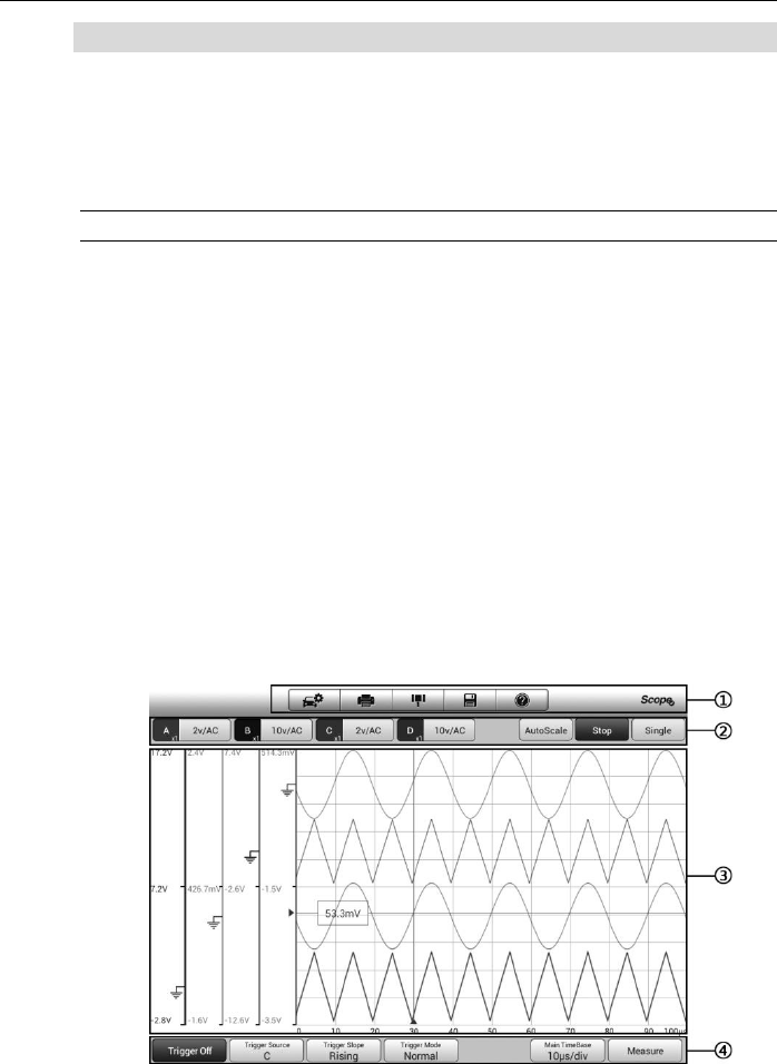
Figure 16-4 Sample Oscilloscope Application Screen Layout
Oscilloscope Operations Screen Layout and Operations
122
1. Top Toolbar – used for configurations of various settings and operations
of the scope
2. Functional Buttons on the top – used for configurations of channel
activation, measurement scale and trigger settings
3. Measurement Grid - displays measurements of voltage against time
4. Functional Buttons at the bottom – used for configurations of trigger,
time base, and measurement parameter display settings.
16.4.1 Top Toolbar
The top toolbar contains various functional buttons with options for operations
and configurations of the MaxiScope, the operations of which are described in
the table below:
Table 16-1 Toolbar Buttons
Button
Name
Description
Car
This option provides a library of waveforms. Selecting
one allows automatic set-up of the scope to capture a
waveform of the specified waveform type. (Coming
soon)
Print
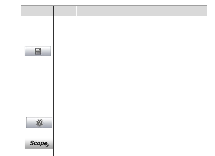
Saves and prints a copy of the displayed data. See 3.3.1
Printing Operation for additional information on page 17.
Tool
Tapping this button opens a settings window with
options to configure various measurement tools for
reference and assessment of data analysis:
Tap
Select a Math Channel
option
to select a
match channel.
Tap
Select a Probe
option to select a predefined
probe.
Tap
Cache Setting
to set the cache.
Oscilloscope Operations Screen Layout and Operations
123
Button
Name
Description
Save
Tapping this button opens a submenu, on which displays
5 options allowing you to save, record and plays back
the waveform data.
Tap
Save current page
to take a screenshot
image.
Tap
Record data
to save the current waveform
data.
Tap
Save Ref
to save a
copy of an existing
signal waveform
as reference.
Tap
Review data
allows selecting and reviewing
the previously stored waveform recordings.
Tap
Recall Ref
to retrieve the saved reference
waveforms.
All saved images are stored in the Data Manager
application for later reviews. See
Data Manager
Operations
on page 84.
Help
Provides instructions or tips for operations of various
functions.
Scope
Icon
Indicates the scope connection status. Tapping the icon
allows to reset the USB connection when
communication with the Scope Module fails. See 16.5
Troubleshooting
on page 129 for more information.
Math Channel
A math channel is virtual channel generated by mathematical function of the
input channel. It can be displayed in a scope in the same way as an input
signal, and like an input signal it has its own measure axis, scaling and color.
The MaxiScope module has a set of built-in math channels for the most
important functions, including “A+B” (the sum of channels A and B) and “A-B”
(the difference between channels A and B).
To use a math channel:
1. Tap the Tool button in the Top Menu.
2. Tap the Select a Math Channel option on the left column.
3. Tap the desired option on the right column to enable the math
channel in the channel list.
4. The Math Channel displays on the MaxiScope screen.
Oscilloscope Operations Screen Layout and Operations
124
Probe
A probe is any transducer, measuring device or other accessory that you
connect to an input channel of your MaxiScope module.
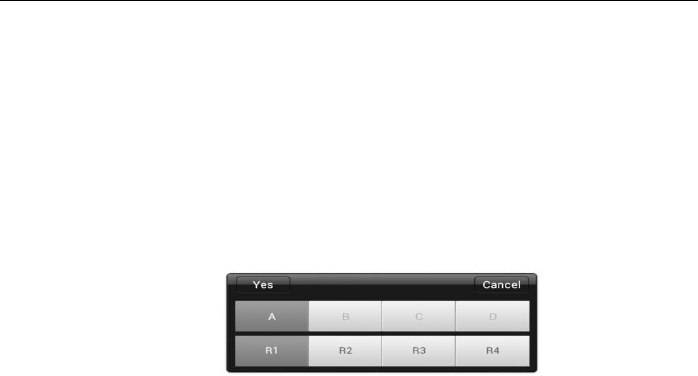
Reference Waveform
A Reference Waveform is a copy of an existing signal waveform saved as a
reference. It can be retrieved to display as a comparative reference to
examine a live signal. Up to 4 reference waveforms can be saved.
Figure 16-5 Ref. Waveform Save Window
To create a Reference Waveform:
1. Tap the Tool button in the Top Menu.
2. Select Save Ref. in the dropdown menu.
3. Select the channel to which the desired waveform belongs.
4. Name the reference waveform by selecting R1, R2, R3 or R4 in the
popup window.
5. Tap on the Yes icon to save, or No icon to cancel.
Recall Reference
The saved reference waveforms can be retrieved by clicking Recall Ref in the
dropdown menu of the Tool button.
To recall reference waveforms:
1. Tap Tool button on the Top Menu.
2. Select Recall Ref in the dropdown menu and a popup window will
display. Available reference waveform items are highlighted in blue.
3. Select the desired reference waveform by ticking the check box
alongside.
4. Tap Yes and the selected reference waveform will appear on the
scope screen.

Oscilloscope Operations Screen Layout and Operations
125
Figure 16-6 Recall Reference Waveform Window
16.4.2 Functional Buttons
This group of buttons is used for configurations of channel activation,
measurement scale and trigger settings, the operations of which are described
below:
Channel Control Buttons A/B/C/D - tapping each button allows you to
activate or deactivate the corresponding channel; long pressing the
button opens a window, which allows you to select and configure
appropriate probes for specific tests.
The Channel Control Buttons are displayed in different colors as follows:
A. Red
B. Green
C. Blue
D. Pink
AC/DC Coupling and Voltage Scale Buttons – tapping this button
opens a dropdown menu, on which you can select AC or DC
measurements and adjust voltage measurement scales.
The Auto voltage scale option enables the scope to adjust the voltage
scale automatically to capture the signal.
AutoScale – tapping this button enables automatic set-up of the voltage
scale and time base for the signals received.
Start/Stop – tapping this button turns on/off the scope.
Single – tapping this button activates the Single trigger mode when the
trigger is on. The Single trigger mode configures the trigger to occur once
when the scope captures the first signal waveform by the preset trigger
point.
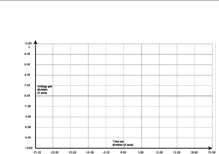
Oscilloscope Operations Screen Layout and Operations
126
16.4.3 Measurement Grid
The 2 control features - Voltage per division and Time per division – enable
the users to adjust the scope settings to suit the particular test measurement.
Figure 16-7 Sample Measurement Grid
Voltage per division – shown down the left side of the screen, referred to
as the Y-axis
Time per division – shown along the bottom of the screen, referred to as
the X-axis
Multiple Scope Channels
The MaxiScope software features multiple channel display which enables
more than one waveform to be displayed at the same time. It is useful for
making comparisons among different signals. The voltage per division for
each channel is adjusted individually while the time base per division is the
same for all channels.
To adjust the voltage scale
1. Tap the specific Y-axis of the corresponding channel to enable scale
adjustment. The selected Y-axis is highlighted with thicker dividing
line.
2. Adjust the voltage scale of the selected channel with the typical
2-finger zoom gestures.
3. The 0 volts is hinted with a pointer reference line. Slide the pointer

Oscilloscope Operations Screen Layout and Operations
127
line up and down to move and view different areas of the scale.
4. Tap once on the screen area outside of the Y-axis to finish the
voltage scale adjustment.
To adjust the time base scale
1. Unselect the Y-axis if it’s activated.
2. Use your 2 fingers to adjust the time base with the typical zoom
gestures on the measurement grid area.
16.4.4 Measurement Rulers
The Measurement Rulers allow the voltage and time duration of a waveform to
be measured precisely. There are 2 kinds of measurement rulers: the vertical
Time Ruler and the horizontal Voltage Ruler.
Tap on the Ruler Activator on the bottom right corner of the measurement
grid and drag it across the screen to the desired position, a Time Ruler is
generated.
The Voltage Ruler can be generated in the similar way by clicking the Ruler
Activator on the top left corner and dragging it downwards.
When Measurement Rulers are generated, a Ruler Table showing time and
voltage values for the corresponding channels will be displayed. The Delta
icon refers to the absolute difference between the values of the 2 rulers, which
can be locked by tapping the Lock icon.
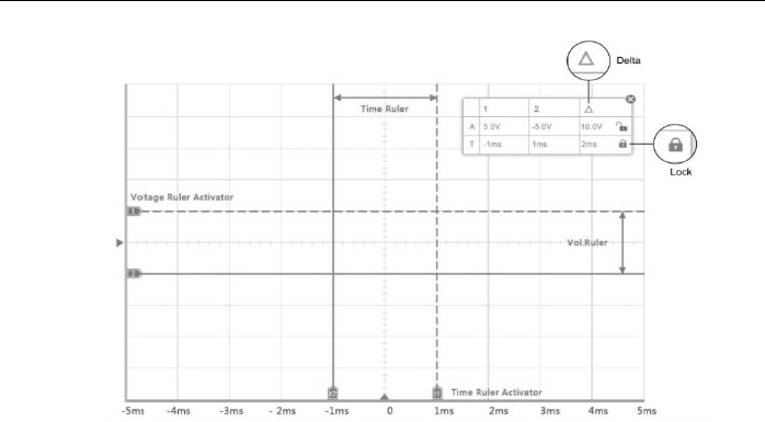
Oscilloscope Operations Screen Layout and Operations
128
Figure 16-8 Measurement Rulers Display
16.4.5 Functional Buttons
This group of buttons includes trigger setting buttons allowing you to set
trigger source and trigger mode, a Time base button for adjustment, and a
Measurement button with options for various measurement types.
Trigger On/Off – taps to turn on/off the trigger. The button displays as
Trigger Off when it is activated, and vice versa.
Once the trigger is activated, a voltage scale reference line and a time
base reference line will be displayed on the measurement grid, the cross
point of the 2 lines indicates the trigger point, allowing users to adjust its
position by moving each of the 2 lines.
Trigger Source – assigns the trigger to a specific channel
Trigger Slope – sets trigger to occur by rising or falling voltage edges
Trigger Mode – configures the trigger mode:
A. Normal Mode – configures the trigger to occur every time when the
captured signal waveform reaches the trigger point, so the scope
starts to draw the waveform when the signal reaches the trigger
point.

Oscilloscope Operations Troubleshooting
129
B. Auto Mode - configures the trigger to occur every time when the
scope captures the signal waveforms by the preset trigger point.
The scope continues to draw the waveforms even when the signal
is not in the trigger point range.
Main Time Base – allows users to select an appropriate time per division.
The time per division (10 divisions) is displayed along the bottom of the
screen. The time base adjustment affects all of the active scope
channels at once.
Measure - allows users to select various types of measurement
parameters to be displayed at the right side of the screen for reference.
A maximum of 5 items each time are allowed to be selected.
To set a specific trigger point
1. Tap the Trigger On button to activate the trigger.
2. Configures the specific trigger source, the trigger slope and the
trigger mode according to the test demand.
3. Tap and slide the voltage scale reference line up or down to the
desired voltage point. The voltage info is displayed in a small
reference box.
4. Tap and slide the time base reference line left or right to the desired
point.
5. Tap Start button on the top right side of the screen to activate the
scope
16.5 Troubleshooting
If the MaxiScope is not communicating with the Display Tablet, you need to do
the followings:
Check if the MaxiScope is properly connected to the Display Tablet
through the supplied USB cable.
If the MaxiScope is already connected to the Display Tablet, but the
communication between the devices has failed, tap the Scope Icon
on the top right side of the screen to reset the USB connection.

Oscilloscope Operations MaxiScope Firmware Update
130
IMPORTANT: All vehicle communications must be terminated before
resetting the USB connection to avoid damage to the devices and the
vehicle. The Internet connection may be aborted during USB reset.
If the communication between the MaxiScope and the Display Tablet
still fails after USB reset, restart the Display Tablet and reconnect
the MaxiScope.
16.6 MaxiScope Firmware Update
The operating software of the MaxiScope is continuously being developed,
and the update package can be downloaded free from the MaxiScope product
webpage on Autel’s website: http://www.autel.com.
To update the MaxiScope firmware
1. Install the CD provided with the MaxiScope tool kit into the
CD-ROM of the computer. The driver installation wizard will load
momentarily.
2. Click on Next on the welcome page.
3. Click the Browse button, and select a destination folder to install
the program, and click Next to continue. Or directly click Next to
continue without changing the default installation folder.
4. Click Install and the Setup.exe program will be installed onto the
computer.
5. After the installation is completed, connect the MaxiScope to the
computer using the USB cable provided by the tool kit.
6. Locate and double click the MaxiScope Update icon on desktop,
and the Firmware Update window will pop up onscreen.
7. Click on Select File to locate the newly downloaded firmware
update package.
8. Click on the dropdown menu icon by the Set Language option at
the top right of the window to select a desired language.
9. Click on Update to start updating.

131
Chapter 17 Digital Inspection Operations
The Digital Inspection application configures the Display Tablet to operate as a digital
video scope by simply connecting the tablet to a Digital Inspection Camera. This
function allows you to examine difficult-to-reach areas normally hidden from sight, with
the ability to record digital still images and videos, which offers you an economical
solution to inspect machinery, facilities, and infrastructure in a safe and quick way.
WARNINGS & IMPORTANTS:
Follow these instructions to reduce the risk of injury from electric shock,
entanglement and other causes and prevent tool damage.
Do not place the imager head and cable into anything or anywhere that
may contain a live electric charge or moving parts, which increases the risk
of electric shock or entanglement injuries.
Do not use the imager head cable to modify surroundings, clear pathways
or clogged areas.
When inspection is completed, carefully withdraw the imager head and
cable from the inspection area.
The imager head cable were waterproof to a depth of 3m (10’), greater
depths may cause leakage into the imager head cable and cause electric
shock or damage the tool.
The working temperature of the imager head is between 32 °F (0 °C) and
113 °F (45 °C).
Check-Ups:
FOR AUTOMOBILES: Ensure the automobile is not running during
inspection. Metal and liquid under the hood may be hot. Don’t get oil or gas
on the imager head.
FOR PIPES: If you suspect a metal pipe could contain an electric charge,
have a qualified electrician to check the pipe before using.
FOR WALLS: For inspecting the inside walls, be sure to shut off the circuit
breaker to the whole house before using the tool.
WORK AREA: Ensure the work area has sufficient light.
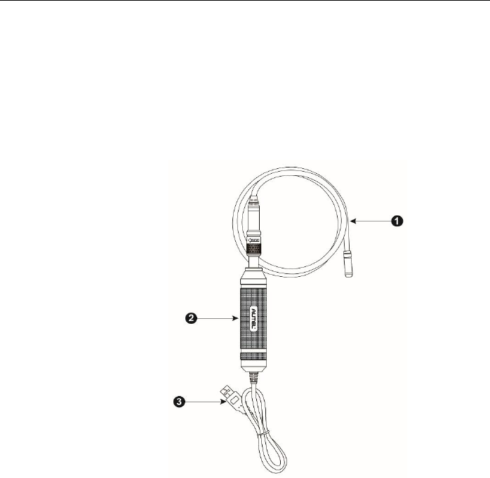
Digital Inspection Operations Additional Accessories
132
17.1 Additional Accessories
The Digital Inspection Camera and its fittings are the additional accessories.
Both sizes (8.5 mm and 5.5 mm) of the imager head are optional and
available for purchase along with the standard MaxiSys tool kit.
Digital Inspection Camera
Figure 17-1 Digital Inspection Camera
1. Removable Imager Head Cable – connects to the tool when performing
digital inspections for image and video viewing
2. Handgrip – ergonomically designed handle for comfortable grips and
agile operation
3. USB Cable – connects the Digital Inspection Camera to MaxiSys tablet

Digital Inspection Operations Additional Accessories
133
Imager Head Accessories
Figure 17-2 8.5mm Imager Head Accessories
1. Magnet – picks up small metal objects, such as dropped rings or screws
2. Hook – unclogs obstacles and picks up wires in the pipes or confined
areas
3. Mirror – helps to look around corners and see the unreachable areas
Figure 17-3 5.5mm Imager Head Accessories
1. Mirror – helps to look around corners and see the unreachable areas
2. Magnet - picks up small metal objects, such as dropped rings or screws
Accessory Assembly
For 8.5mm Imager Head
The three accessories, including the Magnet, Hook, and Mirror (Figure 17-2),
can be attached to the Imager Head with the same manner described below:
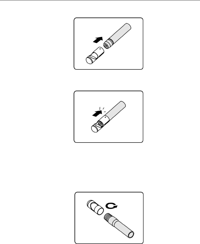
Digital Inspection Operations Additional Accessories
134
1. Hold the accessory and the imager head.
2. Slip the end of the accessory over the imager head and then fix the
accessory.
For 5.5mm Imager Head
The two accessories, including the Magnet and Mirror (Figure 17-3), can be
attached to the Imager Head with the same manner described below:
1. Hold the accessory and the imager head.
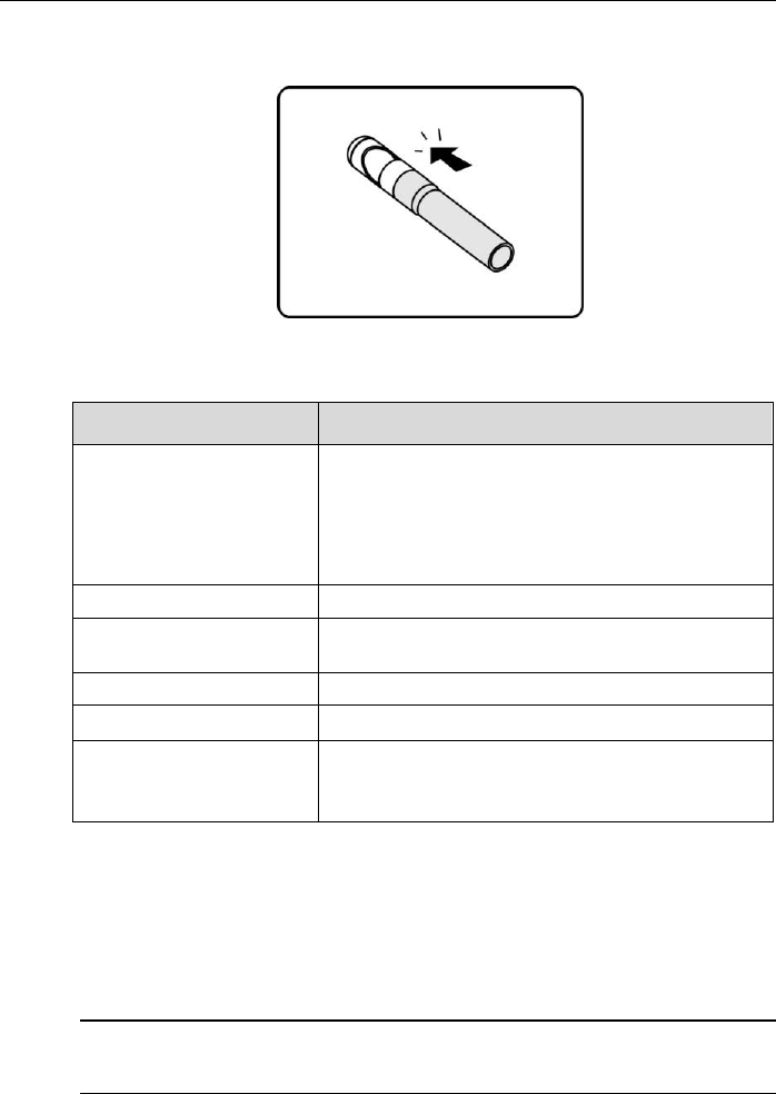
Digital Inspection Operations Operations
135
2. Screw the thread part of the accessory over the imager head to fix the
accessory.
17.1.1 Technical Specifications
Item
Description
Optimal
Viewing Distance
1" to 14" (2.54cm to 35.56cm) with 8.5mm
diameter imager head
3/8" to 12" (0.95cm to 30cm) with 5.5mm
diameter imager head
Image Capture
JPG images (640x480) AVI videos (320 x 240)
Operating Temperature
Main Unit: 0°C to 55°C (ambient)
Cable: -10°C to 70°C
Storage Temperature
-20°C to 75°C (ambient)
Waterproof
Imager head and cable to 1m
Weight
0.3kg with 8.5mm diameter imager head
0.2kg with 5.5mm diameter imager head
17.2 Operations
Before performing the Digital Inspection application, the Imager Head Cable
must be connected to the Display Tablet through the USB port. Install the
correct imager head accessories for use in the appropriate application.
NOTE: When in operation, the imager head cable can be bent into a certain
shape. This may help you operate the cable into confined areas.

Digital Inspection Operations Operations
136
To take pictures using the Digital Inspection application
1. Connect the Imager Head Cable to the USB port on the top side of
the Display Tablet.
2. If not already done, power up the Display Tablet.
3. Tap the Digital Inspection application on the MaxiSys Job Menu.
The Digital Inspection application interface displays, showing a
camera operating screen. The default camera is now the Imager
head.
4. Select the camera icon at the lower right corner to take photos.
5. Focus the image to be captured in the view finder by adjusting and
properly locating the imager head cable.
6. Tap the blue ring on the operating screen. The view finder now
shows the captured picture and auto-saves the taken photo.
7. Tap the thumbnail image on the top right corner of the screen to view
the stored image, slide the screen left and right to view the images
one by one.
8. Tap on the selected image and the edit toolbar instantly displays.
9. Tap the appropriate button to share, delete, or edit the image.
10. Tap the Back or Home button on the Navigation bar at the bottom of
the screen to exit the Digital Inspection application.
To record a video using the Digital Inspection application
1. Connect the Imager Head Cable to the USB port on the top side of
the Display Tablet.
2. If not already done, power up the Display Tablet.
3. Tap the Digital Inspection application on the MaxiSys Job Menu.
The Digital Inspection application interface displays, showing a
camera operating screen. The default camera is now the Imager
head.
4. Select the video icon at the lower right corner to record a video.
5. Properly locate the imager head cable to focus the inspection scene
for recording.

Digital Inspection Operations Operations
137
6. Tap the red ring on the operating screen to start recording.
7. Tap the red circle again to stop recording. The recorded video is
automatically saved to the system Gallery.
8. Tap the thumbnail image on the top right corner to review the
recorded video.
9. Tap the Play button to play the video.
10. Tap on the selected video and the edit toolbar instantly displays.
11. Tap the appropriate button to share, delete, or edit the video.
12. Tap the Back or Home button on the Navigation bar at the bottom of
the screen to exit the Digital Inspection application.
To configure various settings for the work mode of the imager head
1. Tap button at the bottom edge of the circle.
2. Select each item to make appropriate adjustments.
For more tips and detailed information about the camera application, please
refer to associated Android documentations.

138
Chapter 18 Maintenance and Service
To ensure that the MaxiSys diagnostic tablet and the combined VCI unit perform at their
optimum level, we advise that the product maintenance instructions covered in this
section is read and followed.
18.1 Maintenance Instructions
The following shows how to maintain your devices, together with precautions
to take.
Use a soft cloth and alcohol or a mild window cleaner to clean the touch
screen of the tablet.
Do not use any abrasive cleansers, detergent, or automotive chemicals
to the tablet.
Maintain the devices in dry conditions and keep them within normal
operating temperatures.
Dry your hands before using the tablet. The touch screen of the tablet
may not work if the touch screen is moist, or if you tap the touch screen
with wet hands.
Do not store the devices in humid, dusty or dirty areas.
Check the housing, wiring, and connectors for dirt and damage before
and after each use.
At the end of each work day, wipe the device housing, wiring, and
connectors clean with a damp cloth.
Do not attempt to disassemble your tablet or the VCI unit.
Do not drop or cause severe impact to the devices.
Use only authorized battery chargers and accessories. Any malfunction
or damage caused by the use of unauthorized battery charger and
accessories will void the limited product warranty.
Ensure that the battery charger does not come in contact with conductive
objects.
Do not use the tablet beside microwave ovens, cordless phones and
some medical or scientific instruments to prevent signal interference.

Maintenance and Service Troubleshooting Checklist
139
18.2 Troubleshooting Checklist
A. When the Display Tablet does not work properly:
Make sure the tablet has been registered online.
Make sure the system software and diagnostic application software
are properly updated.
Make sure the tablet is connected to the Internet.
Check all cables, connections, and indicators to see if the signal is
being received.
B. When battery life is shorter than usual:
This may happen when you are in an area with low signal strength.
Turn off your device if is not in use.
C. When you cannot turn on the tablet:
Make sure the tablet is connected to a power source or the battery is
charged.
D. When you are unable to charge the tablet:
Your charger maybe out of order. Contact your nearest dealer.
You may be attempting to use the device in an overly hot/cold
temperature. Try changing the charging environment.
Your device may have not been connected to the charger properly.
Check the connector.
NOTE: If your problems persist, please contact Autel’s technical support
personnel or your local selling agent.
18.3 About Battery Usage
Your tablet is powered by a built-in Lithium-ion Polymer battery. This means
that, unlike other forms of battery technology, you can recharge your battery
while some charge remains without reducing your tablet’s autonomy due to
the “battery memory effect” inherent in those technologies.
DANGER: The built-in Lithium-ion Polymer battery is factory replaceable only;
incorrect replacement or tampering with the battery pack may cause an
explosion.

Maintenance and Service About Battery Usage
140
Do not use a damaged battery charger.
Do not disassemble or open crush, bend or deform, puncture or shred.
Do not modify or remanufacture, attempt to insert foreign objects into the
battery, expose to fire, explosion or other hazard.
Make sure to use the charger and USB cables only that come together in
the package. If you use the other charger and USB cables, you might
incur malfunction or failure of the device.
Only use the charging device that has been qualified with device per the
standard. Use of an unqualified battery or charger may present a risk of
fire, explosion, leakage, or other hazard.
Avoid dropping the tablet. If the tablet is dropped, especially on a hard
surface, and the user suspects damage, take it to a service center for
inspection.
The closer you are to your network’s base station, the longer your tablet
usage time because less battery power is consumed for the connection.
The battery recharging time varies depending on the remaining battery
capacity.
Battery life inevitably shortens over time.
Since over charging may shorten battery life, remove the tablet from its
charger once it is fully charged. Unplug the charger, once charging is
complete.
Leaving the tablet in hot or cold places, especially inside a car in summer
or winter, may reduce the capacity and life of the battery. Always keep
the battery within normal temperatures.
18.4 Service Procedures
This section introduces information for technical support, repair service, and
application for replacement or optional parts.
Technical Support
If you have any question or problem on the operation of the product, please:

Maintenance and Service Service Procedures
141
Call 1-855-288-3587/1-855-AUTELUS (North America), or
0086-755-86147779 (China).
Contact the local distributer or agent.
Visit our website http://pro.autel.com or www.autel.com.
Repair Service
If it becomes necessary to return your device for repair, please download the
repair service form from www.autel.com, and fill in the form. The following
information must be included:
Contact name
Return address
Telephone number
Product name
Complete description of the problem
Proof-of-purchase for warranty repairs
Preferred method of payment for non-warranty repairs
NOTE: For non-warranty repairs, payment can be made with Visa, Master
Card, or with approved credit terms.
Send the device to your local agent, or to the below address:
8th Floor, Building B1, Zhiyuan,
Xueyuan Road, Xili, Nanshan,
Shenzhen, 518055, China
Other Services
You can purchase the optional accessories directly from Autel’s authorized
tool suppliers, and/or your local distributor or agent.
Your purchase order should include the following information:
Contact information
Product or part name
Item description
Purchase quantity

142
Chapter 19 Compliance Information
FCC Compliance
FCC ID: WQ8MAXISYSMS906TS (for MaxiSys MS906TS)
This equipment has been tested and found to comply with the limits for a Class B digital
device, pursuant to Part 15 of the FCC Rules. These limits are designed to provide
reasonable protection against harmful interference in a residential installation. This
equipment generates uses and can radiate radio frequency energy and, if not installed
and used in accordance with the instructions, may cause harmful interference to radio
communications. However, there is no guarantee that interference will not occur in a
particular installation. If this equipment does cause harmful interference to radio or
television reception, which can be determined by turning the equipment off and on, the
user is encouraged to try to correct the interference by one or more of the following
measures:
Reorient or relocate the receiving antenna.
Increase the separation between the equipment and receiver.
Consult the dealer or an experienced radio/TV technician for help.
This device complies with part 15 of the FCC Rules. Operation is subject to the
following two conditions:
(1) This device may not cause harmful interference, and
(2) This device must accept any interference received, including interference that may
cause undesired operation.
Changes or modifications not expressly approved by the party responsible for
compliance could void the user’s authority to operate the equipment.
SAR:
The device has been tested and is compliant with SAR limits, users can obtain
information on SAR report and compliance. Nevertheless, the device should be used in
such a manner that the potential for human contact is minimized during normal
operation.
The exposure standard for wireless devices employs a unit of measurement known as
the Specific Absorption Rate, or SAR. The SAR limit set by the FCC is 1.6 W/Kg. Tests
for SAR are conducted using standard operating positions accepted by the FCC with

Compliance Information Important Information
143
the device transmitting at its highest certified power level in all tested frequency bands.
Although the SAR is determined at the highest certified power level, the actual SAR
level of the device while operating can be well below the maximum value. This is
because the device is designed to operate at multiple power levels so as to use only the
power required to reach the network. To avoid the possibility of exceeding the FCC
radio frequency exposure limits, human proximity to antenna should be minimized.

144
Chapter 20 Warranty
12-Month Limited Warranty
Autel Intelligent Technology Corp., Ltd. (the Company) warrants to the original retail
purchaser of this MaxiSys Diagnostic Device, that should this product or any part
thereof during normal consumer usage and conditions, be proven defective in material
or workmanship that results in product failure within twelve (12) months period from the
date of delivery, such defect(s) will be repaired, or replaced (with new or rebuilt parts)
with Proof of Purchase, at the Company’s option, without charge for parts or labor
directly related to the defect(s).
The Company shall not be liable for any incidental or consequential damages arising
from the use, misuse, or mounting of the device. Some states do not allow limitation on
how long an implied warranty lasts, so the above limitations may not apply to you.
This warranty does not apply to:
a) Products subjected to abnormal use or conditions, accident, mishandling, neglect,
unauthorized alteration, misuse, improper installation or repair or improper
storage;
b) Products whose mechanical serial number or electronic serial number has been
removed, altered or defaced;
c) Damage from exposure to excessive temperatures or extreme environmental
conditions;
d) Damage resulting from connection to, or use of any accessory or other product
not approved or authorized by the Company;
e) Defects in appearance, cosmetic, decorative or structural items such as framing
and non operative parts.
f) Products damaged from external causes such as fire, dirt, sand, battery leakage,
blown fuse, theft or improper usage of any electrical source.
IMPORTANT: All contents of the product may be deleted during the process of repair.
You should create a back-up copy of any contents of your product before delivering the
product for warranty service.