Automotive Data Solutions VW1 REMOTE CAR STARTER User Manual
Automotive Data Solutions Inc. REMOTE CAR STARTER
UserManual.wiki
>
Automotive Data Solutions
>
VW1 User Manual
User Manual
Navigation menu
Upload a User Manual
Namespaces
Wiki Guide
HTML
PDF
Info
Views
User Manual
Discussion / Help
Navigation
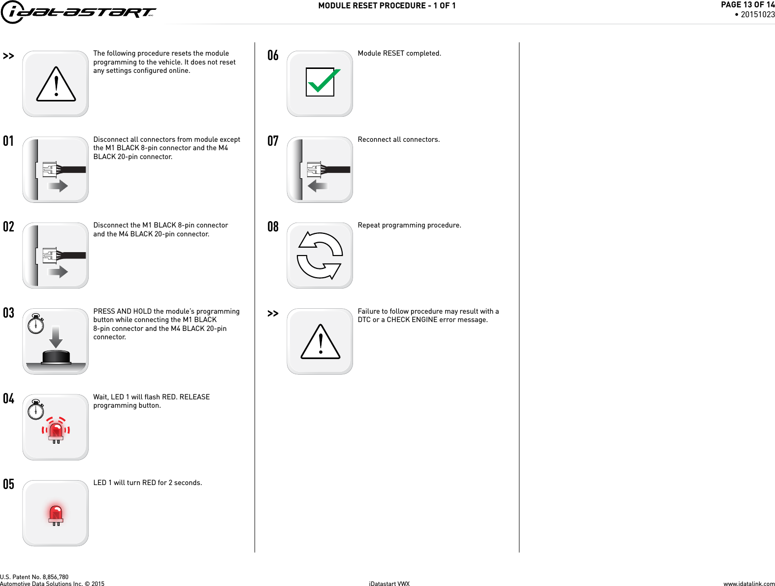
![U.S. Patent No. 8,856,78001 [4x] 02ENGINESTARTSTOPOFF ACC ON STARTON 03 04 05 06 07 08ENGINESTARTSTOPOFF ACC ON STARTOFF 09_________________________________>>F_________________________________REMOTE PROGRAMMING PROCEDURE - 1 OF 1WARNING: Complete the module programming procedure and tach programming procedure before programming the remotes. A maximum of four [4x] remotes per system.Set ignition to ON position.Press and release the antenna button, then press and hold the antenna button. The antenna’s leds will turn solid BLUE.Parking Light will fl ash once [1x].Press once [1x] on the LOCK button of each remote.The antenna’s leds will fl ash BLUE once [1x] for each successful pairing.Release the antenna button. The antenna’s leds will turn OFF.Set ignition to OFF position.Remote Programming Procedure completed.To program an additional remote as second vehicle mode: Follow steps 1 to 4. Press twice [2x] on the “F” button then press once [1x] on the LOCK button of the remote. Follow steps 6 to 9.www.idatalink.comAutomotive Data Solutions Inc. © 2015 iDatastart VWXPAGE 6 OF 14• 20151023](https://usermanual.wiki/Automotive-Data-Solutions/VW1/User-Guide-3280534-Page-6.png)
![U.S. Patent No. 8,856,780>> 01 02ENGINESTARTSTOPOFF ACC ON STARTON 03 04 05ENGINESTARTSTOPOFF ACC ON STARTOFF 06 >> VALET MODE PROGRAMMING PROCEDURE - 1 OF 1NOTE: In Valet Mode, the Remote starter is not functional. Keyless entry, Lock and Unlock will remain functional. See RF kit user manual for alternate valet mode programming.Time restriction. Complete next step within 7 seconds.Cycle ignition ON twice [2x OFF/ON] rapidly.Press and release the BRAKE pedal three times [3x].Parking Light will fl ash once [1x] then will fl ash twice [2x].Set ignition to OFF position.Valet Mode Programming Procedure completed.To exit valet mode: repeat steps 1 to 5.www.idatalink.comAutomotive Data Solutions Inc. © 2015 iDatastart VWXPAGE 7 OF 14• 20151023](https://usermanual.wiki/Automotive-Data-Solutions/VW1/User-Guide-3280534-Page-7.png)
![U.S. Patent No. 8,856,780REMOTE STARTER ERROR CODES - 1 OF 1REMOTE STARTER ERROR CODES:NOTES[X] NUMBER OF PARKING LIGHT FLASHESDIAGNOSTICI WARNING: The following applies only when the parking lights are connected and supported by the system.01 Engine running. 02 Key in ignition at ON position.II After a remote starter failure, the parking lights will fl ash three [3x] times, then will fl ash [X] number times to indicate an error code. See table.03 Door is open.04 Trunk is open.05 Foot brake is ON. 06 Hood is open.07 The reservation is OFF. (Manual transmission only)08 Tach failure.09 The vehicle is moving (VSS).10 System is in Valet Mode. 11 CAN communication failure12 RS not synchronized. Start vehicle with OEM key for 15 sec before trying a new RS sequence.13 Bypass problem.REMOTE STARTER SHUTDOWN ERROR CODES:NOTES[Y] NUMBER OF PARKING LIGHT FLASHESDIAGNOSTICI WARNING: The following applies only when the parking lights are connected and supported by the system.01 Engine tach signal is lost.02 Emergency brake is lost.II If the engine shuts down after a remote starter sequence: Press and hold the Trunk button and the Start button at the same time for 2.5 seconds when using a 1-WAY remote. OR Press once [1x] on button “4” when using a 2-WAY remote. The parking lights will fl ash four [4x] times, then will fl ash [Y] number times to indicate an error code. See table.03 Foot brake is ON. 04 Hood is open.05 Engine RPM limiter is ON.06 Glow plug timeout error.07 Vehicle is moving (VSS).08 N/A09 N/A10 Door is open.11 CAN communication failure during RS sequence.12 RS not synchronized. Start vehicle with OEM key for 15 sec before trying a new RS sequence.13 Takeover is not allowed.14 Shutdown error, board overheat protection.www.idatalink.comAutomotive Data Solutions Inc. © 2015 iDatastart VWXPAGE 12 OF 14• 20151023](https://usermanual.wiki/Automotive-Data-Solutions/VW1/User-Guide-3280534-Page-12.png)