Avaya 555 233 116 Users Manual Installation For Adjuncts And Peripherals MultiVantage Software
555-233-116 to the manual a75f2357-1f14-44c4-a387-d8b4cc06fd43
2014-12-13
: Avaya Avaya-555-233-116-Users-Manual-122255 avaya-555-233-116-users-manual-122255 avaya pdf
Open the PDF directly: View PDF ![]() .
.
Page Count: 246 [warning: Documents this large are best viewed by clicking the View PDF Link!]
- ==============
- MAIN MENU
- MASTER INDEX
- GLOSSARY
- ==============
- Installation for Adjuncts and Peripherals for Avaya MultiVantage Software
- Contents
- About this book
- 1 909A/B universal coupler
- 2 Auxiliary power supplies
- Local auxiliary power supply
- Applications that require auxiliary power
- Sources of auxiliary local power
- Required safety precautions
- 1145B power supply
- Circuit protection
- Mountings
- Installing the wall mounting
- Installing the 1146 power distribution unit
- Installing the expanded power distribution unit
- Powering up and testing AC and DC power
- Wire the 1146 power distribution unit
- Replacing the batteries
- Storing the batteries in inactive units
- Repairing short circuits and resetting red LEDs
- 1151A and 1151A2 power supplies
- 3 Extenders for 2-wire DCP endpoints
- 4 Data modules and asynchronous data units
- Understanding RS-232 communications
- Installation procedure
- Obtain required equipment
- Set hardware options
- Connect data modules
- Connecting a single data module
- Connecting multiple data modules to the system
- Configuring the 7400A data module
- Using the 7400A menu system
- Configuring the 7400A for data communications equipment (DCE) applications
- Configuring the 7400B Data Module
- Configuring the 7400C HSL (high- speed link) data module
- Configuring the 7400D data module
- Configuring the 8400B Plus data module
- Configuring the ExpressRoute 1000 data module
- Administer the data modules
- Asynchronous data units (ADU)
- 5 External modems
- 6 Printers
- 7 DEFINITY LAN gateway system
- 8 Terminal server installation
- 9 DS1/T1 CPE loopback jack
- Installing a loopback jack
- Administering the loopback jack
- Loopback testing with a smart jack
- Testing a loopback jack without a smart jack
- 10 ISDN converters and adapters
- 11 Stratum 3 clock
- 12 Busy tone disconnect equipment for non-U.S. installations
- 13 Call detail recording (CDR) option settings
- 14 DEFINITY INADS
- 15 Malicious call trace
- 16 Music-on-hold
- 17 Paging and announcement equipment
- Background information
- Loudspeaker paging for MCC1, SCC1, CMC1, or G600 Media Gateways
- ESPA radio paging
- External ringing
- Queue warning indicator
- Loudspeaker paging for G700 Media Gateways
- 18 Multimedia communications products: MMCX, MMCH, ESM
- 19 Property management system (PMS)
- A Connector and cable pinout charts
- Index

,QVWDOODWLRQIRU$GMXQFWVDQG3HULSKHUDOV
IRU$YD\D0XOWL9DQWDJH6RIWZDUH
Release 1.2
555-233-116
Issue 4
October 2002
Copyright 2002, Avaya Inc.
All Rights Reserved
Notice
Every effort was made to ensure that the information in this document
was complete and accurate at the time of printing. However, informa-
tion is subject to change.
Preventing Toll Fraud
“Toll fraud” is the unauthorized use of your telecommunications sys-
tem by an unauthorized party (for example, a person who is not a cor-
porate employee, agent, subcontractor, or is not working on your
company's behalf). Be aware that there may be a risk of toll fraud
associated with your system and that, if toll fraud occurs, it can result
in substantial additional charges for your telecommunications ser-
vices.
Avaya Fraud Intervention
If you suspect that you are being victimized by toll fraud and you need
technical assistance or support, in the United States and Canada, call
the Technical Service Center's Toll Fraud Intervention Hotline at
1-800-643-2353.
How to Get Help
For additional support telephone numbers, go to the Avaya Web site:
http://www.avaya.com/support/
If you are:
• Within the United States, click Escalation Lists, which includes
escalation phone numbers within the USA.
• Outside the United States, click Escalation Lists then click Glo-
bal Escalation List, which includes phone numbers for the
regional Centers of Excellence.
Providing Telecommunications Security
Telecommunications security (of voice, data, and/or video communi-
cations) is the prevention of any type of intrusion to (that is, either
unauthorized or malicious access to or use of) your company's tele-
communications equipment by some party.
Your company's “telecommunications equipment” includes both this
Avaya product and any other voice/data/video equipment that could be
accessed via this Avaya product (that is, “networked equipment”).
An “outside party” is anyone who is not a corporate employee, agent,
subcontractor, or is not working on your company's behalf. Whereas, a
“malicious party” is anyone (including someone who may be other-
wise authorized) who accesses your telecommunications equipment
with either malicious or mischievous intent.
Such intrusions may be either to/through synchronous (time-multi-
plexed and/or circuit-based) or asynchronous (character-, message-, or
packet-based) equipment or interfaces for reasons of:
• Utilization (of capabilities special to the accessed equipment)
• Theft (such as, of intellectual property, financial assets, or toll
facility access)
• Eavesdropping (privacy invasions to humans)
• Mischief (troubling, but apparently innocuous, tampering)
• Harm (such as harmful tampering, data loss or alteration,
regardless of motive or intent)
Be aware that there may be a risk of unauthorized intrusions associ-
ated with your system and/or its networked equipment. Also realize
that, if such an intrusion should occur, it could result in a variety of
losses to your company (including but not limited to, human/data pri-
vacy, intellectual property, material assets, financial resources, labor
costs, and/or legal costs).
Responsibility for Your Company’s Telecommunications Security
The final responsibility for securing both this system and its net-
worked equipment rests with you - Avaya’s customer system adminis-
trator, your telecommunications peers, and your managers. Base the
fulfillment of your responsibility on acquired knowledge and
resources from a variety of sources including but not limited to:
•Installation documents
•System administration documents
•Security documents
•Hardware-/software-based security tools
•Shared information between you and your peers
•Telecommunications security experts
To prevent intrusions to your telecommunications equipment, you and
your peers should carefully program and configure:
•Your Avaya-provided telecommunications systems and their
•interfaces
•Your Avaya-provided software applications, as well as their
•underlying hardware/software platforms and interfaces
•Any other equipment networked to your Avaya products.
Voice Over Internet Protocol (VoIP)
If the equipment supports Voice over Internet Protocol (VoIP) facili-
ties, you may experience certain compromises in performance, reli-
ability and security, even when the equipment performs as warranted.
These compromises may become more acute if you fail to follow
Avaya's recommendations for configuration, operation and use of the
equipment. YOU ACKNOWLEDGE THAT YOU ARE AWARE OF
THESE RISKS AND THAT YOU HAVE DETERMINED THEY
ARE ACCEPTABLE FOR YOUR APPLICATION OF THE EQUIP-
MENT. YOU ALSO ACKNOWLEDGE THAT, UNLESS
EXPRESSLY PROVIDED IN ANOTHER AGREEMENT, YOU
ARE SOLELY RESPONSIBLE FOR (1) ENSURING THAT YOUR
NETWORKS AND SYSTEMS ARE ADEQUATELY SECURED
AGAINST UNAUTHORIZED INTRUSION AND (2) BACKING
UP YOUR DATA AND FILES.
Standards Compliance
Avaya Inc. is not responsible for any radio or television interference
caused by unauthorized modifications of this equipment or the substi-
tution or attachment of connecting cables and equipment other than
those specified by Avaya Inc. The correction of interference caused by
such unauthorized modifications, substitution or attachment will be
the responsibility of the user. Pursuant to Part 15 of the Federal Com-
munications Commission (FCC) Rules, the user is cautioned that
changes or modifications not expressly approved by Avaya Inc. could
void the user’s authority to operate this equipment.
Product Safety Standards
This product complies with and conforms to the following interna-
tional Product Safety standards as applicable:
Safety of Information Technology Equipment, IEC 60950, 3rd Edition
including all relevant national deviations as listed in Compliance with
IEC for Electrical Equipment (IECEE) CB-96A.
Safety of Information Technology Equipment, CAN/CSA-C22.2
No. 60950-00 / UL 60950, 3rd Edition

Safety Requirements for Customer Equipment, ACA Technical Stan-
dard (TS) 001 - 1997
One or more of the following Mexican national standards, as applica-
ble: NOM 001 SCFI 1993, NOM SCFI 016 1993, NOM 019 SCFI
1998
The equipment described in this document may contain Class 1
LASER Device(s). These devices comply with the following stan-
dards:
EN 60825-1, Edition 1.1, 1998-01
21 CFR 1040.10 and CFR 1040.11.
The LASER devices operate within the following parameters:
•Maximum power output: -5 dBm to -8 dBm
•Center Wavelength: 1310 nm to 1360 nm
Luokan 1 Laserlaite
Klass 1 Laser Apparat
Use of controls or adjustments or performance of procedures other
than those specified herein may result in hazardous radiation expo-
sures. Contact your Avaya representative for more laser product infor-
mation.
Electromagnetic Compatibility (EMC) Standards
This product complies with and conforms to the following interna-
tional EMC standards and all relevant national deviations:
Limits and Methods of Measurement of Radio Interference of Infor-
mation Technology Equipment, CISPR 22:1997 and EN55022:1998.
Information Technology Equipment – Immunity Characteristics –
Limits and Methods of Measurement, CISPR 24:1997 and
EN55024:1998, including:
•Electrostatic Discharge (ESD) IEC 61000-4-2
•Radiated Immunity IEC 61000-4-3
•Electrical Fast Transient IEC 61000-4-4
•Lightning Effects IEC 61000-4-5
•Conducted Immunity IEC 61000-4-6
•Mains Frequency Magnetic Field IEC 61000-4-8
•Voltage Dips and Variations IEC 61000-4-11
•Powerline Harmonics IEC 61000-3-2
•Voltage Fluctuations and Flicker IEC 61000-3-3
Federal Communications Commission Statement
Part 15:
For MCC1, SCC1, G600, and CMC1 Media Gateways:
For the G700 Media Gateway:
Part 68: Answer-Supervision Signaling. Allowing this equipment to
be operated in a manner that does not provide proper answer-supervi-
sion signaling is in violation of Part 68 rules. This equipment returns
answer-supervision signals to the public switched network when:
•answered by the called station,
•answered by the attendant, or
•routed to a recorded announcement that can be administered by
the customer premises equipment (CPE) user.
This equipment returns answer-supervision signals on all direct
inward dialed (DID) calls forwarded back to the public switched tele-
phone network. Permissible exceptions are:
•A call is unanswered.
•A busy tone is received.
•A reorder tone is received.
Avaya attests that this registered equipment is capable of providing
users access to interstate providers of operator services through the use
of access codes. Modification of this equipment by call aggregators to
block access dialing codes is a violation of the Telephone Operator
Consumers Act of 1990.
For MCC1, SCC1, G600, and CMC1 Media Gateways:
This equipment complies with Part 68 of the FCC rules. On the rear of
this equipment is a label that contains, among other information, the
FCC registration number and ringer equivalence number (REN) for
this equipment. If requested, this information must be provided to the
telephone company.
For the G700 Media Gateway:
This equipment complies with Part 68 of the FCC rules and the
requirements adopted by the ACTA. Located prominently on this
equipment is a label that contains, among other information, a product
identifier in the format US:AAAEQ##TXXXX. The digits represented
by ## are the ringer equivalence number (REN) without a decimal
point (for example, 03 is a REN of 0.3). If requested, this number must
be provided to the telephone company.
The REN is used to determine the quantity of devices which may be
connected to the telephone line. Excessive RENs on the telephone line
may result in devices not ringing in response to an incoming call. In
most, but not all areas, the sum of RENs should not exceed 5.0. To be
certain of the number of devices that may be connected to a line, as
determined by the total RENs, contact the local telephone company.
REN is not required for some types of analog or digital facilities.
Note: This equipment has been tested and found to comply with
the limits for a Class A digital device, pursuant to Part 15 of the
FCC Rules. These limits are designed to provide reasonable pro-
tection against harmful interference when the equipment is oper-
ated in a commercial environment. This equipment generates,
uses, and can radiate radio frequency energy and, if not installed
and used in accordance with the instruction manual, may cause
harmful interference to radio communications. Operation of this
equipment in a residential area is likely to cause harmful interfer-
ence in which case the user will be required to correct the inter-
ference at his own expense.
Note: This equipment has been tested and found to comply with
the limits for a Class B digital device, pursuant to Part 15 of the
FCC Rules. These limits are designed to provide reasonable pro-
tection against harmful interference in a residential installation.
This equipment generates, uses, and can radiate radio frequency
energy and, if not installed and used in accordance with the
instruction manual, may cause harmful interference to radio
communications. However, there is no guarantee that radio inter-
ference will not occur in a particular installation. If this equip-
ment does cause harmful interference to radio or television
reception, which can be determined by turning the equipment off
and on, the user is encouraged to try to correct the interference
by one or more of the following measures:
•Reorient or relocate the receiving antenna.
•Increase the separation between the equipment and
receiver.
•Connect the equipment into an outlet on a circuit different
from that to which the receiver is connected.
•Consult the dealer or an experienced radio/TV technician
for help.

Means of Connection
Connection of this equipment to the telephone network is shown in the
following tables.
For MCC1, SCC1, G600, and CMC1 Media Gateways:
For the G700 Media Gateway:
If the terminal equipment (for example, the MultiVantage™ Solution
equipment) causes harm to the telephone network, the telephone com-
pany will notify you in advance that temporary discontinuance of ser-
vice may be required. But if advance notice is not practical, the
telephone company will notify the customer as soon as possible. Also,
you will be advised of your right to file a complaint with the FCC if
you believe it is necessary.
The telephone company may make changes in its facilities, equipment,
operations or procedures that could affect the operation of the equip-
ment. If this happens, the telephone company will provide advance
notice in order for you to make necessary modifications to maintain
uninterrupted service.
If trouble is experienced with this equipment, for repair or warranty
information, please contact the Technical Service Center at
1-800-242- 2121 or contact your local Avaya representative. If the
equipment is causing harm to the telephone network, the telephone
company may request that you disconnect the equipment until the
problem is resolved.
A plug and jack used to connect this equipment to the premises wiring
and telephone network must comply with the applicable FCC Part 68
rules and requirements adopted by the ACTA. A compliant telephone
cord and modular plug is provided with this product. It is designed to
be connected to a compatible modular jack that is also compliant. It is
recommended that repairs be performed by Avaya certified techni-
cians.
The equipment cannot be used on public coin phone service provided
by the telephone company. Connection to party line service is subject
to state tariffs. Contact the state public utility commission, public ser-
vice commission or corporation commission for information.
This equipment, if it uses a telephone receiver, is hearing aid compati-
ble.
Canadian Department of Communications (DOC) Interference
Information
For MCC1, SCC1, G600, and CMC1 Media Gateways:
This Class A digital apparatus complies with Canadian ICES-003.
Cet appareil numérique de la classe A est conforme à la norme
NMB-003 du Canada.
For the G700 Media Gateway:
This Class B digital apparatus complies with Canadian ICES-003.
Cet appareil numérique de la classe B est conforme à la norme
NMB-003 du Canada.
This equipment meets the applicable Industry Canada Terminal Equip-
ment Technical Specifications. This is confirmed by the registration
number. The abbreviation, IC, before the registration number signifies
that registration was performed based on a Declaration of Conformity
indicating that Industry Canada technical specifications were met. It
does not imply that Industry Canada approved the equipment.
DECLARATIONS OF CONFORMITY
United States FCC Part 68 Supplier’s Declaration of Conformity
(SDoC)
Avaya Inc. in the United States of America hereby certifies that the
equipment described in this document and bearing a TIA TSB-168
label identification number complies with the FCC’s Rules and Regu-
lations 47 CFR Part 68, and the Administrative Council on Terminal
Attachments (ACTA) adopted technical criteria.
Avaya further asserts that Avaya handset-equipped terminal equip-
ment described in this document complies with Paragraph 68.316 of
the FCC Rules and Regulations defining Hearing Aid Compatibility
and is deemed compatible with hearing aids.
Copies of SDoCs signed by the Responsible Party in the U. S. can be
obtained by contacting your local sales representative and are avail-
able on the following Web site:
http://www.avaya.com/support/
All MultiVantage™ system products are compliant with FCC Part 68,
but many have been registered with the FCC before the SDoC process
was available. A list of all Avaya registered products may be found at:
http://www.part68.org/
by conducting a search using “Avaya” as manufacturer.
Manufacturer’s Port
Identifier FIC Code SOC/REN/
A.S. Code Network
Jacks
Off/On premises station OL13C 9.0F RJ2GX,
RJ21X,
RJ11C
DID trunk 02RV2-T 0.0B RJ2GX,
RJ21X
CO trunk 02GS2 0.3A RJ21X
02LS2 0.3A RJ21X
Tie trunk TL31M 9.0F RJ2GX
Basic Rate Interface 02IS5 6.0F, 6.0Y RJ49C
1.544 digital interface 04DU9-BN 6.0F RJ48C,
RJ48M
04DU9-IKN 6.0F RJ48C,
RJ48M
04DU9-ISN 6.0F RJ48C,
RJ48M
120A3 channel service unit 04DU9-DN 6.0Y RJ48C
Manufacturer’s Port
Identifier FIC Code SOC/REN/
A.S. Code Network
Jacks
Ground Start CO trunk 02GS2 0.5A RJ11C
DID trunk 02RV2-T AS.0 RJ11C
Loop Start CO trunk 02LS2 0.5A RJ11C
1.544 digital interface 04DU9-BN 6.0Y RJ48C
04DU9-DN 6.0Y RJ48C
04DU9-IKN 6.0Y RJ48C
04DU9-ISN 6.0Y RJ48C
Basic Rate Interface 02IS5 6.0F RJ49C

European Union Declarations of Conformity
Avaya Inc. declares that the equipment specified in this document
bearing the “CE” (Conformité Europeénne) mark conforms to the
European Union Radio and Telecommunications Terminal Equipment
Directive (1999/5/EC), including the Electromagnetic Compatibility
Directive (89/336/EEC) and Low Voltage Directive (73/23/EEC). This
equipment has been certified to meet CTR3 Basic Rate Interface (BRI)
and CTR4 Primary Rate Interface (PRI) and subsets thereof in CTR12
and CTR13, as applicable.
Copies of these Declarations of Conformity (DoCs) can be obtained
by contacting your local sales representative and are available on the
following Web site:
http://www.avaya.com/support/
Japan
For MCC1, SCC1, G600, and CMC1 Media Gateways:
This is a Class A product based on the standard of the Voluntary Con-
trol Council for Interference by Information Technology Equipment
(VCCI). If this equipment is used in a domestic environment, radio
disturbance may occur, in which case, the user may be required to take
corrective actions.
For the G700 Media Gateway:
This is a Class B product based on the standard of the Voluntary Con-
trol Council for Interference by Information Technology Equipment
(VCCI). If this equipment is used in a domestic environment, radio
disturbance may occur, in which case, the user may be required to take
corrective actions.
To order copies of this and other documents:
Call: Avaya Publications Center
Voice 1.800.457.1235 or 1.207.866.6701
FAX 1.800.457.1764 or 1.207.626.7269
Write: Globalware Solutions
200 Ward Hill Avenue
Haverhill, MA 01835 USA
Attention: Avaya Account Management
E-mail: totalware@gwsmail.com

Contents
Issue 4 October 2002 7555-233-116
About this book 15
■Overview 15
■Conventions used in this book 18
Systems and circuit packs 19
Admonishments 19
Physical dimensions 20
■Antistatic protection 20
■Remove/install circuit packs 20
■Security 21
■Standards compliance 21
■LASER product 22
■Trademarks 22
■How to get this book on the Web 22
■How to get help 23
■Tell us what you think 23
1 909A/B universal coupler 25
2 Auxiliary power supplies 29
■Local auxiliary power supply 30
■Applications that require auxiliary power 30
■Sources of auxiliary local power 31
■Required safety precautions 31
■1145B power supply 32
Circuit protection 32
Mountings 33
Installing the wall mounting 33
Installing the 1146 power distribution unit 35
Installing the expanded power distribution unit 36
Powering up and testing AC and DC power 38

Contents
555-233-1168Issue 4 October 2002
Wire the 1146 power distribution unit 39
Replacing the batteries 40
Storing the batteries in inactive units 40
Repairing short circuits and resetting red LEDs 40
■1151A and 1151A2 power supplies 40
Desk mounting 42
Wall mounting 42
Standards compliance 42
3 Extenders for 2-wire DCP endpoints 43
■2-wire DCP endpoints 43
■DCP extender, stand alone 45
■DCP extender, rack mount 46
4 Data modules and asynchronous data units 47
■Understanding RS-232 communications 48
■Installation procedure 49
■Obtain required equipment 50
■Set hardware options 50
Setting 7400A data module hardware options 50
Setting 7400B data module hardware options 52
■Connect data modules 54
Connecting a single data module 55
Connecting multiple data modules to the system 56
■Administer the data modules 95
■Asynchronous data units (ADU) 98

Contents
Issue 4 October 2002 9555-233-116
5 External modems 99
■Hardware required when configuring modems 99
■Paradyne COMSPHERE 3715 100
Configuring the 3715 for CMS 100
Configuring the 3715 for modem pooling 100
■Paradyne COMSPHERE 3810 Plus and 3811 Plus 101
Configuring the 3810 Plus and 3811 Plus modems 101
■Paradyne COMSPHERE 3910 101
Configuring the 3910 for CMS 102
■U.S. Robotics modems 109
Configuring U.S. Robotics modems 109
■Multi-Tech MT5634ZBA-USB 110
Configuring the MT5634ZBA-USB modem 110
■Administration 110
6 Printers 113
■Connecting printers using TCP/IP 113
Task list 113
Administering adjunct parameters 114
Using the downloadable reliable session-layer
protocol (RSP) tool 115
7 DEFINITY LAN gateway system 117
■What is the DEFINITY LAN gateway? 117
How the DLG application works 117
How is the DLG application is packaged 118
The MAPD DLG 118
The co-resident DLG 119
Switch-based connectivity — co-resident DLG 119

Contents
555-233-11610 Issue 4 October 2002
8 Terminal server installation 121
■Overview 121
■Installing and administering the terminal server 122
Administering the IOLAN+ 124
Potential failure scenarios and repair actions 131
■Administering IP node names 131
■Administering IP services 132
9 DS1/T1 CPE loopback jack 135
■Installing a loopback jack 135
With a smart jack 135
Without a smart jack 136
■Administering the loopback jack 137
■Loopback testing with a smart jack 137
Testing the DS1 span from the ICSU to the loopback jack 137
Testing the DS1 span from the smart jack to the
network interface termination or fiber multiplexer (MUX) 143
Testing the DS1 span from the loopback jack to
the smart jack 143
■Testing a loopback jack without a smart jack 151
Configurations using fiber multiplexers 156
10 ISDN converters and adapters 157
■Converters for single-carrier cabinets 158
PRI-to-DASS and PRI-to-DPNSS converters 158
PRI-to-BRI converter 159
■Converters for multi-carrier cabinets 160
PRI-to-DASS and PRI-to-DPNSS converters 160
PRI-to-BRI converter 161

Contents
Issue 4 October 2002 11555-233-116
11 Stratum 3 clock 163
■Set clock options 163
Cabling the Stratum 3 clock 165
Stratum 3 clock wiring installation procedure 167
12 Busy tone disconnect equipment for
non-U.S. installations 171
13 Call detail recording (CDR) option settings 173
■Connecting CDR equipment 173
■Using other equipment as the CDR output devices 174
■Sources of administration information 174
■Connecting a CDR device 174
Task list 174
Administering CDR parameters 174
■Using the downloadable reliable
session-layer protocol (RSP) tool 176
14 DEFINITY INADS 179
Analog loopback 179
Administration 181
Partner installation 181
INADS connection with power fail transfer 182
INADS connection without power fail transfer 184
PARTNER administration 185
DEFINITY ECS administration 186
Installation test (all installations) 187
■Connectivity for INADS on S8700 and S8300 media servers 187
Example of an ART script file 187

Contents
555-233-11612 Issue 4 October 2002
15 Malicious call trace 189
16 Music-on-hold 191
■For MCC1, SCC1, CMC1, and G600 Media Gateways 191
Registered music source 192
Nonregistered music source 192
■For G700 Media Gateways 194
17 Paging and announcement equipment 197
■Background information 197
IP configurations 198
Configuration using the S8700 Media Server in a
multi-connect configuration controlling a G700
Media Gateway 198
S8700 Media Server in a multi-connect configuration networked
with a S8300 Media Server in a G700 Media Gateway and a
DEFINITY CSI 199
Configuration using the S8700 Media Server with IP connect 200
■Loudspeaker paging for MCC1, SCC1,
CMC1, or G600 Media Gateways 201
Loudspeaker paging without paging adapter 202
Loudspeaker paging access without universal coupler 203
Loudspeaker paging with universal coupler 203
■ESPA radio paging 204
■External ringing 205
■Queue warning indicator 205
■Loudspeaker paging for G700 Media Gateways 206

Contents
Issue 4 October 2002 13555-233-116
18 Multimedia communications
products: MMCX, MMCH, ESM 207
■MASI for MMCX 207
Direction connection 208
Main distribution frame connection 209
■Wideband endpoints 209
Nonsignaling configuration 209
Signaling configuration 210
■Multimedia call handling (MMCH) 212
Connect the endpoints 212
Setup and test the MMCH installation 214
Place conversion test call 221
Expansion services module 221
Administration 222
Place test call 223
Troubleshooting 223
19 Property management system (PMS) 225
■Connecting the property management system (PMS) 225
■Connecting a terminal and/or journal printer 226
Using data modules 226
Using an asynchronous data unit (ADU)
and a data line circuit pack 227
■Connecting PMS and printers using TCP/IP 227
Task list 227
Administering adjunct parameters 228
Using the downloadable reliable session-layer protocol tool 229


Issue 4 October 2002 15555-233-116
About this book
This book provides procedures for installing software (adjuncts) and equipment
(peripherals) to Avaya media servers and gateways. Not all adjuncts and
peripherals are addressed in this book. For those adjuncts and peripherals not
addressed, we are supplying other resources for the information.
The information in this book is intended for use by:
■Trained field installation and maintenance personnel
■Technical support personnel
■Network engineers and technicians
■Design center personnel
■Sales associates
■Business partners
Overview
Avaya media servers and gateways can work with a wide range of external
equipment, applications, and peripherals. For the purposes of this book, we define
the terms as follows:
■Adjuncts are software products that work with the various Avaya servers or
gateways.
■Peripherals are hardware products that connect directly or remotely to
Avaya media servers or gateways.
Be aware that some equipment and software work only with certain releases. See
your Avaya representative for the most current compatibility information.

About this book
555-233-116
16 Issue 4 October 2002
Table 1 provides a list of current adjuncts and peripherals, and where installation
information exists.
Table 1. Adjuncts and peripherals resource list
Adjunct/Peripheral Resource
909A/B Universal Coupler Chapter 1
AUDIX AUDIX Installation
AUDIX Voice Power Installation and Maintenance Guide
Auxiliary Power Supplies Chapter 2
Basic Call Management
System (BCMS) View Basic Call Management System (BCMS) Operations
Busy Tone Disconnect
Equipment for Non-U.S.
Installations
Chapter 12
Call Detail Recording
(CDR) Option Settings Chapter 13
CallVisor ASAI LAN
Gateway CallVisor ASAI DEFINITY LAN Gateway over MAPD
Installation, Administration, and Maintenance
CentreVu Agent CentreVu Agent Installation and Administration
CentreVu Call Management
System (CMS) CentreVu Call Management System Software Installation
and Setup
CentreVu Explorer CentreVu Explorer User Guide
CentreVu Supervisor CentreVu Supervisor —Installation and Getting Started
Conversant INTUITY CONVERSANT System Customer Assist
Technical Operations
Data Modules and ADUs Chapter 4
DCS Connections Chapter 9
DEFINITY INADS Chapter 14
DEFINITY LAN Gateway
System Chapter 7
DEFINITY Wireless
Personal Comm Mgr. Interface for the DEFINITY Wireless Business System
Guide
DS1/T1 CPE Loopback
Jack Chapter 9
Expansion Services Module
(ESM) Chapter 18
Continued on next page

Overview
Issue 4 October 2002 17555-233-116
External Alerting
Equipment Chapter 16
Internet Call Center CentreVu Internet Solutions Documentation CD-ROM
Internet Call Center Solution Guide
Internet Telephony
Gateway Internet Telephony Server-Enterprise Hardware Installation
Quick Reference
Intuity AUDIX Internet Messaging for the Intuity AUDIX Multimedia
Messaging System, Installation
Intuity Interchange INTUITY Interchange System Supporting Documentation
ISDN Converters and
Adapters Chapter 10
Loudspeaker Paging Chapter 17
Malicious Call Trace Chapter 15
Modems, external Chapter 5
Multimedia Call Exchange
MMCX Chapter 18
Multimedia Call Handling
(MMCH) Chapter 18
Multipoint Control Unit
(MCU)/CRS MultiPoint Conferencing Unit Installation and Test
Music-on-hold Chapter 16
Paging and Announcement
Equipment Chapter 17
Pollable Storage Unit
(PSU) Pollable Storage Unit Installation
Printers Chapter 6
Property Management
System Chapter 19
Stratum 3 Clock Chapter 11
Voice and Data Terminals Chapter 3
Table 1. Adjuncts and peripherals resource list
Adjunct/Peripheral Resource
Continued on next page

About this book
555-233-116
18 Issue 4 October 2002
Conventions used in this book
Become familiar with the following terms and conventions. They help you use this
book with your Avaya MultiVantage™ Software.
■Commands are printed in bold face as follows: command.
We show complete commands in this book, but you can usually type an
abbreviated version of the command. For example, list configuration
station can be typed as list config sta.
■Screen displays and names of fields are printed in constant width as
follows: screen display.
A screen is any form displayed on your computer or terminal monitor.
■Variables are printed in italics as follows: variable.
■Keys and buttons are printed as follows: KEY.
■To move to a certain field, you can use the TAB key, arrows, or the ENTER
key (the ENTER key may appear as the RETURN key on your keyboard).
■If you use terminal emulation software, you need to determine what keys
correspond to ENTER, RETURN, CANCEL, HELP, NEXT PAGE, etc.
■In this book we use the terms “telephone” and “voice terminal” to refer to
phones.
■We show commands and screens from the newest release of MultiVantage
Software and refer to the most current books. Please substitute the
appropriate commands for your system and refer to the manuals you have
available.
■If you need help constructing a command or completing a field entry,
remember to use HELP.
—When you press HELP at any point on the command line, a list of
available commands appears.
—When you press HELP with your cursor in a field on a screen, a list of
valid entries for that field appears.
■The status line or message line can be found near the bottom of your
monitor display. This is where the system displays messages for you.
Check the message line to see how the system responds to your input.
Write down the message if you need to call our helpline.
■When a procedure requires you to press ENTER to save your changes, the
screen you were working on clears and the cursor returns to the command
prompt.
The message line shows “command successfully completed” to
indicate that the system accepted your changes.

Conventions used in this book
Issue 4 October 2002 19555-233-116
Systems and circuit packs
■The word “system” is a general term encompassing all references to an
Avaya media server or gateway running MultiVantage Software.
■The term “ASAI” is synonymous with the newer CallVisor ASAI.
■Circuit pack codes (for example, TN780 or TN2182B) are shown with the
minimum acceptable alphabetic suffix (like the “B” in the code TN2182B).
Generally, an alphabetic suffix higher than that shown is also acceptable.
However, not every vintage of either the minimum suffix or a higher suffix
code is necessarily acceptable. A suffix of “P” means that firmware can be
downloaded to that circuit pack.
■The term “cabinet” refers to the external casing (shell) of an MCC1, SCC1,
CMC1, or G600 Media Gateway. Circuit packs are installed in the cabinet
in a specific carrier (row) and in a specific slot within that carrier.
■The designation “UUCSSpp” refers to the location (address) of a circuit
pack in cabinet-carrier-slot order. In this address designation, UU is the
cabinet number, C is the carrier letter, SS is the slot number of a specific
circuit pack, and pp (if applicable) is a specific port on the circuit pack. A
sample address for port 4 on a circuit pack on an MCC1 Media Gateway
might look like this: 02A0704.
■A G700 Media Gateway uses media modules instead of circuit packs. The
media module address is designated as XXXVSpp, where XXX is the
administered number of the G700 Media Gateway, VS is the slot number of
a specific media module location on the G700 Media Gateway, and pp (if
applicable) is a specific port on the media module. The V is not a variable
and needs to be included in the command exactly where shown. A sample
address for port 4 on an MM711 Media Module on a G700 Media Gateway
might look like this: 002V304. An S8300 Media Server, if installed in a
G700 Media Gateway, must be in location V1.
Admonishments
Admonishments in this book have the following meanings:
Tip:
Draws attention to information that you may find helpful.
NOTE:
Draws attention to information that you must heed.
!CAUTION:
Denotes possible harm to software, possible loss of data, or possible service
interruptions.

About this book
555-233-116
20 Issue 4 October 2002
!WARNING:
Denotes possible harm to hardware or equipment.
!DANGER:
Denotes possible harm or injury to your body.
!SECURITY ALERT:
Indicates when system administration may leave your system open to toll
fraud.
Physical dimensions
■All physical dimensions in this book are in English units (feet [ft]) followed
by metric (centimeter [cm]) in parenthesis.
■Wire gauge measurements are in AWG followed by the diameter in
millimeters in parenthesis
Antistatic protection
!WARNING:
To minimize electrostatic discharge (ESD), always wear an authorized wrist
ground strap. Connect the strap to an approved ground, such as an
unpainted metal surface, before handling circuit packs, media modules, or
any components.
Remove/install circuit packs
!CAUTION:
Do not remove or install control circuit packs (circuit packs with white labels)
when the power is on in an MCC1 Media Gateway. Damage may occur.
Make sure the power is off before removing or installing control circuit packs.
Port circuit packs (circuit packs with gray labels—older version circuit packs
had purple labels) can be safely removed or installed when the power is on.
Do not remove or install media modules when the power is on in a
G700 Media Gateway. Damage may occur. Make sure the power is off
before removing or installing a media module.

Security
Issue 4 October 2002 21555-233-116
Security
To ensure the greatest security possible, Avaya offers services that can reduce
toll fraud liabilities. Contact your Avaya representative for more security
information.
Login security is an attribute of the MultiVantage Software. Advise customers that
their existing passwords expire 24 hours after the upgrade. Also explain that the
new passwords must conform to strict requirements.
System administrators must keep network addresses confidential. A PPN or any
endpoint masquerading as a PPN on the ATM network can seize that EPN and
control it if that EPN is not already connected to its proper PPN.
Standards compliance
The equipment in this document complies with the following standards (as
applicable):
■ITU-T (Formerly CCITT)
■ECMA
■ETSI
■IPNS
■DPNSS
■National ISDN-1
■National ISDN-2
■ISO-9000
■ANSI
■FCC Part 15 and Part 68
■EN55022
■EN50081
■EN50082
■UNI 3.1
■CISPR22
■Australia AS3548 (AS/NZ3548)
■Australia AS3260
■IEC 825
■IEC 950
■UL1459

About this book
555-233-116
22 Issue 4 October 2002
■UL 1950
■CSA C222 Number 225
■TS001
■ILMI 3.1
LASER product
The Avaya Media Gateway may contain a Class 1 LASER device (IEC 825 1993)
if single-mode fiber optic cable is connected to a remote expansion port network
(EPN). The LASER device operates within the following parameters:
!DANGER:
Use of controls or adjustments or performance of procedures other than
those specified herein may result in hazardous radiation exposure.
Contact your Avaya representative for more information.
Trademarks
All trademarks identified by ® or ™ are registered trademarks or trademarks,
respectively, of Avaya, Inc. All other trademarks are the property of their
respective owners.
How to get this book on the Web
If you have internet access, you can view and download the latest version of this
book. To view the book, you must have a copy of Acrobat Reader.
To access the latest version:
1. Access the Avaya Web site at http://www.avaya.com/support/.
2. Click Product Documentation.
3. In the Search Product Documentation dialog box, type the ID number of
this book (555-233-116) and click Search.
4. Find the latest issue number, then click the book title.
5. Download this book.
Power output Wavelength Mode field diameter
-5 dBm 1310 nm 8.8 mm

How to get help
Issue 4 October 2002 23555-233-116
How to get help
If you need additional help, the following resources are available. You may need
to purchase an extended service agreement to use some of these resources. See
your Avaya representative for more information.
■If you are within the United States, go to the Avaya Web site at
http://www.avaya.com/support/ for support telephone numbers. Click
Escalation Lists, which includes escalation phone numbers within specific
regions of the United States.
■For all international resources, contact your local Avaya authorized dealer
for any additional help and questions.
Tell us what you think
Let us know what you like or don’t like about this book. Although we can’t respond
personally to all your feedback, we promise we will read each response we
receive.
Write to us at: Avaya Inc.
Product Documentation Group
1300 W. 120th St.
Westminster, CO 80234 USA
Fax to: 303-538-1741
Send email to: document@avaya.com

About this book
555-233-116
24 Issue 4 October 2002

Issue 4 October 2002 25555-233-116
1
909A/B universal coupler
The 909A/B universal coupler is used with paging and music-on-hold equipment
that is not approved for use with the public network.
NOTE:
The information in this chapter does not apply to the G700 Media Gateway
configurations.
Figure 1 shows a typical 909A/B universal coupler. For additional installation and
switch setting information, refer to 909A/909B Universal Coupler Installation
Instructions.
NOTE:
If the music source is registered by the FCC (in the USA) or an equivalent
body, the 909A/B universal coupler is not required.
909A/B universal coupler
555-233-116
26 Issue 4 October 2002
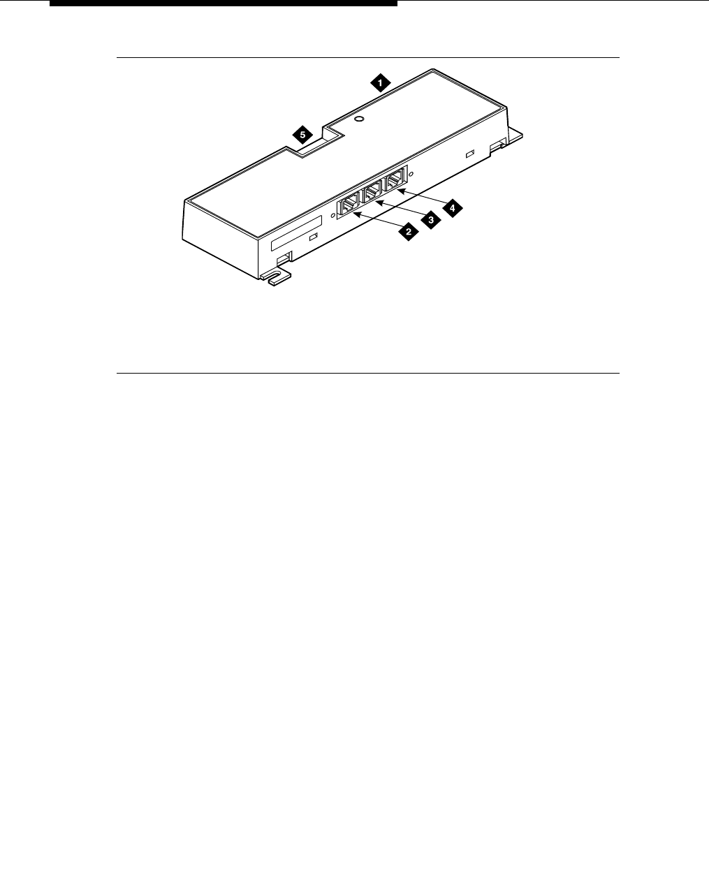
Figure 1. Typical 909A/B universal coupler
The 909A is the direct current (DC) version of the coupler, and cabinet power
supplies -48 VDC power. The 909B is the alternating current (AC) version, and
power is supplied from a separate power supply (such as the KS-22911L2).
The DIP switches on the unit set:
■Protection/Paging selection — For AUX trunk paging and malicious call
trace, set to C2. Set the switch to C1 for all other applications.
■Output attenuation (-9 or -15 dBm) — Setting depends on output level of
music source.
■Output impedance (8 ohms, 1.5 kΩ, and 50 kΩ) —This switch only
requires setting if the Protection/Paging switch is set to C2 and the coupler
is supplying background music to a customer-supplied paging amplifier.
The pinouts for J1, J2, and J3 are provided in Table 2, Table 3, and Table 4. Refer
to these tables when connecting music or paging equipment.
1. 909A/B universal coupler
2. J1 8-pin modular jack
3. J2 8-pin modular jack
4. J3 7-pin modular jack
5. DIP switch location
909
_
brkt KLC 042296

909A/B universal coupler
Issue 4 October 2002 27555-233-116
!CAUTION:
Do not plug the cable into J3 before all cross-connects are completed.
Damage to the 909A/B universal coupler may occur.
Table 2. J1 Pin Assignments (System Connections)
Pin Color Designation Description
1 White-Orange —Not Used
2 Orange PG2/BZ2 Seizure control lead, connected to -48 VDC from
the system or from the 909A/B when the protection
paging switch is set to C2, or to -48 VDC on the
909A/B when protection/paging switch is set to C1
3 White-Green PG1/BZ1 Seizure control lead, connected to SZ lead from
the AUX trunk when the protection/paging switch
is set to C2, or to -48 VDC on the 909A/B when the
protection/paging switch is set to C1
4 Blue R Ring lead
5 White-Blue T Tip lead
7 Green BSY2/BY2 Busy/busy-out lead, connected to S1 lead from the
AUX trunk
7 White-Brown BSY1/BY1 Busy/busy-out lead, connected to S lead from the
AUX trunk
8Brown —Not Used
Table 3. J2 Pin Assignments (Accessory Connections)
Pin Color Designation Description
1 White-Orange CMS1/M1 Customer-supplied music source
2 Orange CMS2/M2 Customer-supplied music source
3 White-Green COS1 Remote busy-out control contact closure from
music source
4 Blue CR Customer ring lead
5 White-Blue CT Customer tip lead
7 Green COS2 Remote busy-out control contact closure from
music source
7 White-Brown CBS1/C1 Seizure indication provided to music source
8 Brown CBS2/C2 Seizure indication provided to music source

909A/B universal coupler
555-233-116
28 Issue 4 October 2002
Figure 2 shows the physical locations of the pins for J1, J2, and J3.
Figure 2. Typical modular jack pinout
Table 4. J3 Pin Assignments (Power Connections)
Pin Color Designation Description
1, 3, 4, & 7 —— Not used
2 Black GRD -48 RET or ground lead from system or
from positive lead of power supply
5 Yellow -48 VDC -48 VDC from system or from negative
lead of power supply
1. J1 and J2 8-pin modular jacks 2. J3 7-pin modular jack
18
2
5
mod_jack RBP 041796

Issue 4 October 2002 29555-233-116
2
Auxiliary power supplies
Nonessential features of the attendant console, such as the optional 27B1
selector console as well as DCP terminals, derive their power from an auxiliary
power source. One console can connect to an Avaya DEFINITY® Server CSI, and
three consoles can connect to each cabinet stack on an Avaya DEFINITY®
Server R.
Each cabinet can derive auxiliary power from the system and through the auxiliary
cable located in the trunk/auxiliary field. Auxiliary power for a primary attendant
console should be provided through this cable so the console remains fully
operational during short power outages.
NOTE:
The information in the first part of this chapter concerning auxiliary power
supplies for the gateway itself (page 30 through page 40) does not apply to
the G700 Media Gateway.
Information beginning on page 40, ‘‘1151A and 1151A2 power supplies’’,
does apply to a G700 Media Gateway under the following conditions:
■if a particular endpoint or adjunct uses a 1151A or 1151A2 power
supply, and
■if that endpoint or adjunct is supported on an S8300/G700.
Please see your Avaya representative for more information.

Auxiliary power supplies
555-233-116
30 Issue 4 October 2002
Local auxiliary power supply
Consoles can use either local or phantom power, depending on the distance
between the console and the cabinet. Over short distances, phantom power is
attractive because no additional hardware is necessary—power is supplied using
the telephone circuit itself. For longer distances, you need a local power supply.
Table 5 shows cabling distances for the 302 attendant console.
Applications that require auxiliary
power
Auxiliary power (local or bulk) is always required for the following:
■Any 8520 telephone
■302-series attendant console
■PassageWay adapter interface
■Any 7500-series telephone whether in passive bus, or point to point (one
per BRI port)
■Any 7500- or 8500-series telephone with an asynchronous data module
■Any 8510 telephone in passive bus or with an asynchronous data module
(unless the 8510 will not be used to support data or video)
■Any 7400-series telephone with XM24 expansion module
■Any 7400-series telephone with adjuncts 7407, 7434 or 7444
■Any 8400-series telephone with adjuncts 8411 or 8434
■Any 4600-series IP telephone
■IP console
The 1145B power supply is required for all installations outside the United States.
Table 5. 302C1 Attendant Console Cabling Distances
24 AWG Wire
(0.27 mm2)
27 AWG Wire
(0.14 mm2)
feet meters feet meters
With selector console:
Phantom-powered 800 244 500 152
Locally powered 5000 1524 3400 1037
Without selector console:
Phantom powered 1400 427 900 274
Locally powered 5000 1524 3400 1037

Sources of auxiliary local power
Issue 4 October 2002 31555-233-116
Sources of auxiliary local power
An attendant console can derive auxiliary power from:
■A bulk power supply, such as the 1145B
A console’s maximum distance from its 1145B auxiliary power source is
800 ft. (244 m) for a 302A1 or 350 ft. (107 m) for a 301B1 and 302C1.
■1151A1 or 1151A2 power supply
Required safety precautions
!DANGER:
When operating power-supply equipment, you must follow basic safety
precautions to reduce the risk of fire, electric shock, and personal injury.
Read and understand all instructions. Follow all warnings and instructions
marked on the products. Follow all the installation instructions when
mounting the product.
Never use a power unit with a power source other than that specified on the
product labels.
Do not try to plug the 3-wire grounding plug into a nongrounding power
outlet. This plug only fits into a grounding power outlet. This is a safety
feature. If you are unable to insert the plug into the outlet, have an electrician
replace the outlet. Do not defeat the safety purpose of the grounding plug.
Do not attach the power supply cord to building surfaces.
Do not overload power outlets.
Do not use this product near water. Do not let anything spill on or into the
unit. Clean only with a dry rag.
Never push objects through openings in the case.
Do not try to disassemble the unit. Return it for repair. Opening or removing
covers may expose you to dangerous voltages. Incorrect reassembly may
cause electric shock when the products are subsequently used.
Power down the unit and refer servicing immediately if the unit is exposed to
water or other liquids, if the unit is dropped or damaged, or if the unit fails to
operate normally.
Never let the operating temperature of the unit exceed the recommended
maximum.

Auxiliary power supplies
555-233-116
32 Issue 4 October 2002
!DANGER:
Do not block or cover the ventilation openings in the case.
Do not let anything rest on the unit.
Do not attempt to recharge batteries. The power unit recharges the batteries
itself. Any other recharging method may cause leaks of corrosive electrolyte
or explosion. Discard discharged batteries as soon as possible. Discharged
batteries are more likely to leak.
Do not store batteries in high temperature areas. Batteries stored in a cold
environment should be protected from condensation during storage and
warming. Batteries should be stabilized at room temperature prior to use
after cold storage. Do not install batteries if the manufacturing date on the
label indicates that the batteries are more than six months old.
1145B power supply
The 1145B power supply powers ISDN/DCP, terminal equipment, adjuncts, and
other customer-supplied external equipment. It supplies -48V, 200 W total and
supports 32 outputs. You can install one ISDN terminal or DCP adjunct per output.
A manual switch on the distribution unit lets the user redirect reserve power to
outputs 1 to 32 so that all outputs get battery reserve power.
An optional 1149 battery and 1146 distribution unit provides uninterruptible -48
VDC power.
!DANGER:
When operating power-supply equipment, you must follow basic safety
precautions to reduce the risk of fire, electric shock and personal injury.
Read, understand, and follow all warnings and instructions. See ‘‘Required
safety precautions’’ on page 31.
Circuit protection
A thermistor current-limits the maximum output of each output to 12 W, but the
average power per output cannot exceed 7.25 W (200/32 = 7.25). An LED
indicates the status of the thermistor. When the LED is ON, there is a short on the
power pair.

1145B power supply
Issue 4 October 2002 33555-233-116
Mountings
The back-up battery mounts on a top plate. The power supply and distribution
units mount on a bottom plate. The plates are normally wall-mounted.
Installing the wall mounting
See Figure 3.
1. Locate one plate directly below the other with the raised letters right side
up. Be sure that the AC power cord can reach the electrical outlet from the
bottom plate. The power cord is about 7.5 ft. (2 m) long.
NOTE:
Up to 4 power supplies can draw current from one 110- or 230-VAC,
20- or 15-A feeder. Use only unswitched receptacles that are not
shared with other equipment.
2. Secure the wall mounting plates to a 3/4-in. (2-cm) plywood mounting
board using the four 1/2-in. #10 wood screws supplied with the plates.
3. Snap the 1145B power supply onto the bottom wall-mounting plate (no
tools are needed).
4. Connect an insulated 17-AWG #12 (1.2-mm) ground wire (or better)
between the ground lug on the power-supply frame and an approved
ground.
The frame ground screw is located next to the AC receptacle, to the left of
the unit.
5. Write the unit number and connectivity information on the front label, next
to the LEDs.
Auxiliary power supplies
555-233-116
34 Issue 4 October 2002
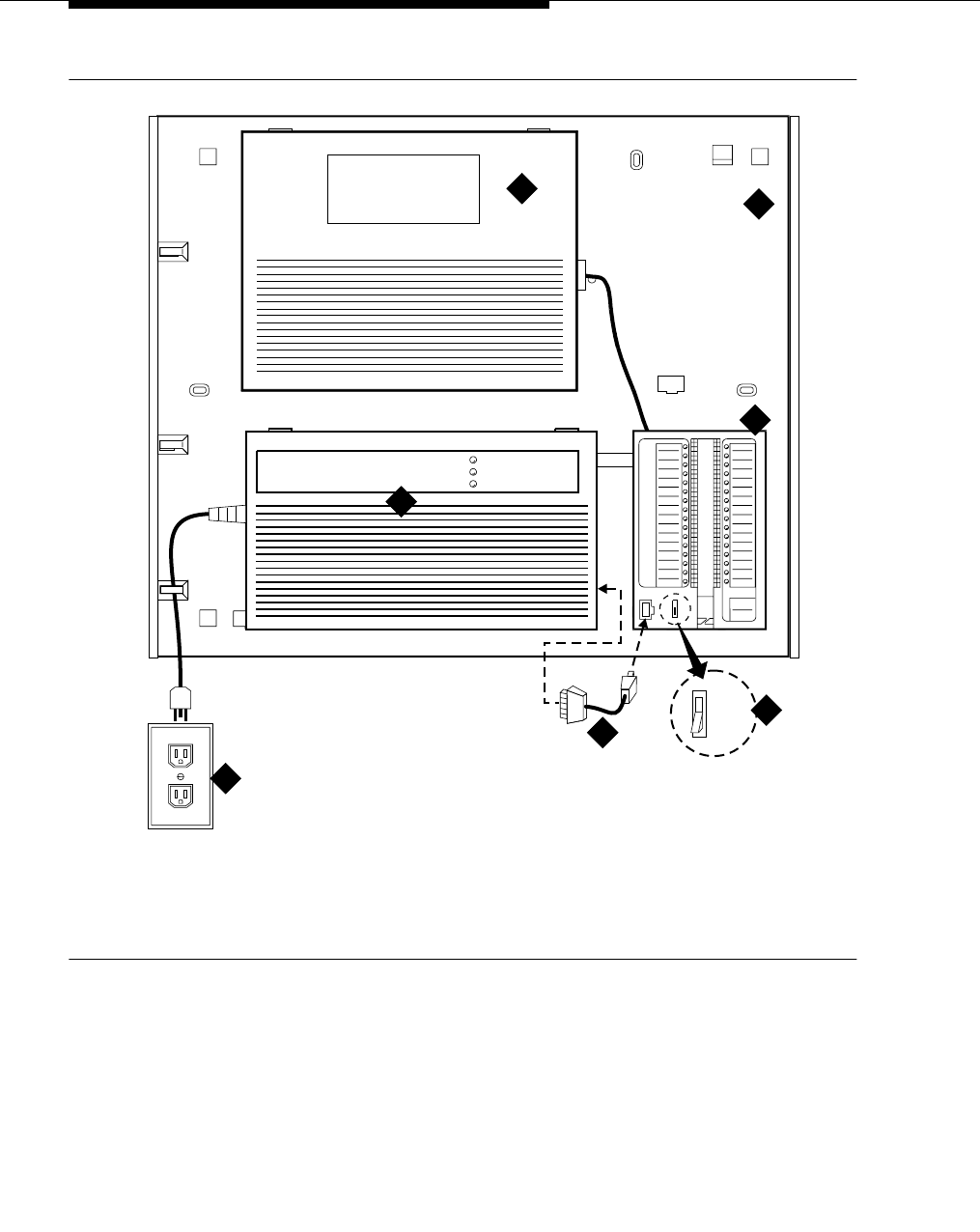
Figure 3. 1145B/1146 mounting arrangement
1. Wall mounting plate
2. Optional battery (1149B shown)
3. 1146 power distribution unit
4. 1145B power unit
5. Power cable
6. Unswitched outlet (120 VAC, 20 A or 230
VAC, 15 A)
7. Battery backup switch setting
pcdf1145 KLC 030100
1
2
3
4
6
1149 Battery
1145 Power Unit On Battery Reserve
Charging Battery
Output Power On
1146 Power Distribution Unit
51-32
1-8 7

1145B power supply
Issue 4 October 2002 35555-233-116
Installing the 1146 power distribution unit
1. Insert and securely tighten the two supplied #8-32 x 1/2-in. shoulder
screws (they have an unthreaded section at the top) into the top holes
designated for 1146 Power Distribution Unit on the bottom plate. Mount the
unit on these two shoulder screws, using the key holes on the back of the
unit.
2. Secure the unit by inserting the #8-32 x 1 in. screw through the bottom of
the unit (just above the wire clips) into the plate and tighten.
3. Set the battery back-up switch option to the 1-32 (down) position to provide
battery back-up to all outputs.
4. Connect the power distribution unit to the power supply with the power
cable. Refer to the power supply’s right-side label to locate the output
power connection.
Installing and wiring the battery
Two types of backup batteries can be used:
To install the battery, proceed as follows.
1. Loosely insert two #10-32 x 1/2-in. shoulder screws in the battery-mounting
holes at the top of the wall mounting plate.
2. Place the keyhole slots in the battery bracket on these two screws. Make
sure the label on the battery is visible.
The battery cord exits from the right side of the bracket.
3. Tighten the screws securely.
4. Plug the battery cord into the right rear receptacle on the power supply.
The right-side label indicates the rear receptacle.
Table 6. Back-Up Batteries
Battery Rating
1148B 2.5 amp-hours
1149B 5 amp-hours

Auxiliary power supplies
555-233-116
36 Issue 4 October 2002
Installing the expanded power distribution unit
You can install a second power-distribution unit for additional 8400- and 8500-
series terminals.
!CAUTION:
Total power cannot exceed 200 W. Consult the chart below for permissible
terminal installations.
Each expanded power distribution unit kit supplies the following items:
■One power distribution unit
■One T-cable
■Two #8-32 x 1/2-in. shoulder screws
■One #8-32 x 1 in. screw
■One spacer bracket
See Figure 4 while installing the power distribution unit:
1. Fasten the spacer bracket to the mounting plate with the #8-32 x 1/2-in.
shoulder screws.
The spacer bracket is not shown in the figure. It is behind the top power
distribution unit.
2. Slide the keyhole slots in the power distribution unit over the shoulder
screws.
3. Insert the #8-32 x 1 in. screw through the distribution unit, through the
spacer bracket, and into the plate. Tighten the screw.
The mounting hole is located just above the wire clip.
4. Set the battery back-up switch to the 1-32 (down) position.
5. Power-down the 1145B as described on the label on the side of the unit.
Table 7. Permissible terminal installations (total power < 200 W)
Terminal mix Maximum numbers Notes
7500-series + 8500-series ISDN 24 + 24
7400-series + 8400-series DCP 24 + 24
8400-series DCP 74
7400-series DCP 74 Average power per
terminal must be
less than 3.126 W
1145B power supply
Issue 4 October 2002 37555-233-116
6. Remove the output power cable between the 1145B and the 1147B units.
The cable will not be reused.
7. Connect the P1 connector end of the T-cable to the bottom power
distribution unit.
8. Connect the P2 connector to the top distribution unit.
9. Connect the P3 connector to the 1145B.
10. Power-up the 1145B as described on the label on the side of the unit.
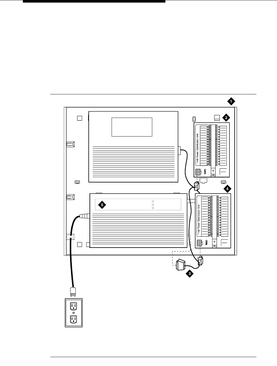
Figure 4. Expanded power distribution unit
1. Wall-mounting plate
2. Optional 1146 power distribution unit
3. T cable (H600-347-G7)
4. Standard 1146 power
distribution unit
5. 1145B power unit
1145 Power Unit
1149 Battery
On Battery Reserve
Charging Battery
Output Power On
1
2
3
4
5
6
7
8
9
10
11
12
13
14
15
16
17
18
19
20
21
22
23
24
25
26
27
28
29
30
31
32
-48V -48V
RTN RT N
Unit No.
Connected To:
1
2
3
4
5
6
7
8
9
10
11
12
13
14
15
16
17
18
19
20
21
22
23
24
25
26
27
28
29
30
31
32
-48V -48V
RTN RT N
Unit No.
Connected To:
0004_1 PDH 06259
6

Auxiliary power supplies
555-233-116
38 Issue 4 October 2002
Powering up and testing AC and DC power
When you power up the unit or interrupt power to a unit, the unit runs an AC or DC
self test. LEDs on the front panel indicate the status of the power supply. The
following table lists the LEDs.
1. Connect the AC power cord to the power supply, and route the cord to an
appropriate AC outlet using the clips provided on the unit.
NOTE:
A maximum of four power supplies can be powered from one
dedicated 110 VAC, 20-A feeder. Use only unswitched receptacles.
2. Start the AC test by plugging the cord into the outlet.
This powers up the power supply.
3. Check AC operation of the 1145B power supply by monitoring the LEDs:
PASS: GREEN and YELLOW are both lit.
FAIL: either GREEN or YELLOW LED is not lit.
4. If the AC test failed, test the AC outlet, power cord, and connections.
5. If the AC test failed, but power is available and the AC power cord and
connections are good, replace the power unit.
6. Once the AC test passes, activate the DC battery-backup supply by
disconnecting the AC plug.
7. Check DC (battery back-up) operation by monitoring the LEDs.
PASS: RED and GREEN are both lit.
FAIL: either RED or GREEN is not lit.
8. If the DC test fails, check the connections.
9. If the DC test fails but the connections are good, replace the batteries and
retest.
10. If the DC test fails after you replace the batteries, replace the power supply.
11. Once the DC test passes, reconnect AC power to the power supply.
Table 8. Power-supply LEDs
LED Color Meaning
GREEN Power supply is providing power
YELLOW Battery is charging (after at most 20 hours, when the battery has
reached full charge, the YELLOW LED should go out)
RED Power supply is on battery reserve
1145B power supply
Issue 4 October 2002 39555-233-116
Wire the 1146 power distribution unit
Wire endpoints to the 1146 while power from the 1145B is on.
1. Install cross-connect jumpers (the label shows polarity) to Pins 7 and 8 of
the appropriate information outlet. Route the wires through the clip
provided on the unit. If a red LED is on, see ‘‘Repairing short circuits and
resetting red LEDs’’ on page 40. Figure 5 shows the connections.
A red LED lights if the associated circuit is connected to shorted wiring or a
shorted terminal.
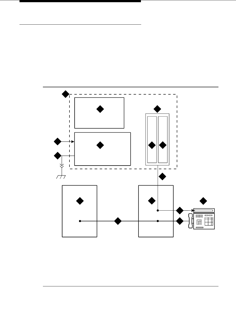
Figure 5. Typical wiring to a terminal
2. Mark lead destinations, unit number, and connectivity information on the
label next to each connector.
1. Power supply kit
2. 2.5, 5.0, or 8.0 A hour battery
3. 1146 power distribution unit
4. 1145B power supply
5. Circuits 1-17
6. Circuits 17-32
7. Port circuit
8. Main distribution frame
9. Modular cord
10. AC input
11. Ground wire
12. ISDN/ display system protocol terminal
13. Circuits 1-32
14. Pins 7 and 8 (display terminal power)
3
45
1
11
2
7
12
13
14
6
8
9 9
10
14

Auxiliary power supplies
555-233-116
40 Issue 4 October 2002
Replacing the batteries
To maintain back-up protection and battery reliability, replace batteries every four
years.
Storing the batteries in inactive units
To prevent leakage when the power unit is not in use for several months or more,
remove the batteries and store them separately.
Repairing short circuits and resetting red LEDs
A red LED next to any of the 32 power output connectors indicates a short circuit
in the building wiring or the terminal equipment. To reset the LED:
1. Disconnect the terminal equipment from the wall jack.
2. If the LED goes off, the terminal equipment is faulty. Replace it.
3. If the LED is still lit, find and repair the short circuit in the building wiring.
4. Reconnect the terminal equipment to the wall jack, and re-test.
1151A and 1151A2 power supplies
The 1151A is a standard (no battery backup) power supply unit. The 1151A2 is a
battery backup version of the 1151A. Either power supply can support one
telephone with or without an adjunct.
The 1151A and 1151A2 power supplies can supply local power to ISDN-T 7400-,
7500-, 8400-, and 8500-series voice terminals connected to a system, and to the
DCP 7444 voice terminal or 302C attendant console that need auxiliary power for
its display. The unit can supply power to adjunct equipment such as S201A and
CS201A speakerphones, or a 500A headset adapter attached to any currently
manufactured analog, DCP, or ISDN-T voice terminal equipped with an adjunct
jack.
The power supply has the following specifications:
■A single output of -48 VDC, 0.4 A.
■Either a 120 VAC 60-Hz power source (105 to 129 VAC) or a 220/230/240
VAC 50-Hz power source (198 to 274 VAC).
■Automatic input voltage selection.
■Output capacity of19.2 W.
■Maximum loop range of 250 ft. (77 m).
■Use of 2 modular jacks. PHONE jack pins 7 and 8 (- and +, respectively)
provide power.
1151A and 1151A2 power supplies
Issue 4 October 2002 41555-233-116
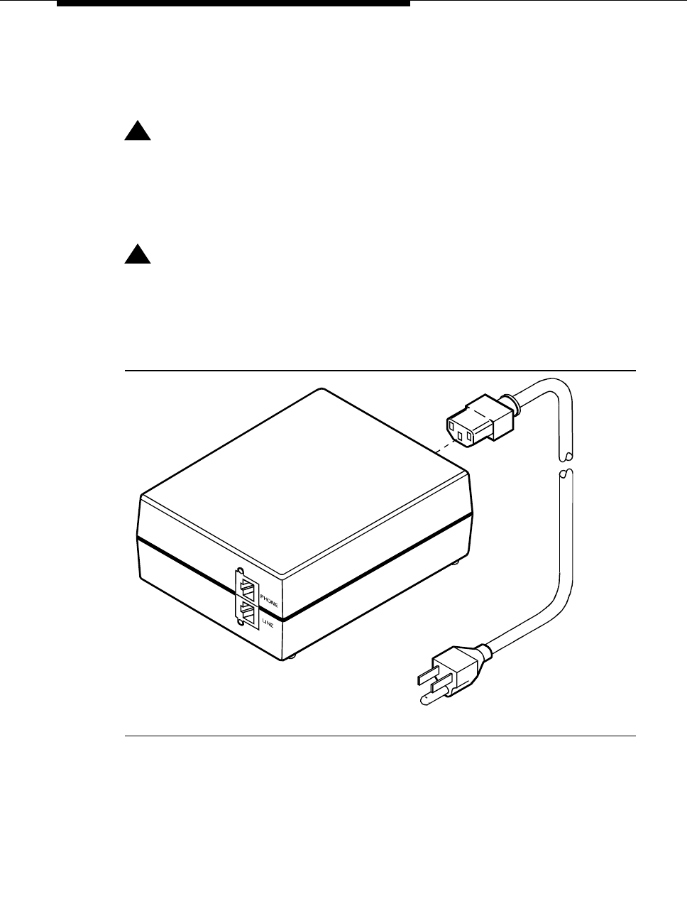
The PHONE and LINE jacks are 8-pin female nonkeyed 757-type jacks that can
accept D4, D7, and D8 modular plug cables. Figure 6 shows a 1151A power
supply. The 1151A2 looks similar.
!DANGER:
When operating power-supply equipment, you must follow basic safety
precautions to reduce the risk of fire, electric shock and personal injury.
Read, understand, and follow all warnings and instructions. See ‘‘Required
safety precautions’’ on page 31.
!CAUTION:
Do not locate the unit within 7 in. (15.25 cm) of the floor.
Use the power supply only with telecommunications equipment, indoors,
and in a controlled environment.
Figure 6. Typical 1151A power supply (front)
pwr_sup1 CJL 051496

Auxiliary power supplies
555-233-116
42 Issue 4 October 2002
Desk mounting
1. Place the power supply on a flat surface such as a desk.
Wall mounting
1. For wall-mounting, use the keyhole slots on the bottom of the chassis.
Standards compliance
The 1151A and 1151A2 power supplies comply with the UL Standard UL 1459,
second edition.
Table 9. Standards compliance
Complies UL 1459
Certified CSA 22.2
Approved EN7950
Approved CE

Issue 4 October 2002 43555-233-116
3
Extenders for 2-wire DCP endpoints
This chapter provides information on 2-wire voice and data terminals and digital
communications protocol (DCP) extenders. Extenders provide off-site employees
with the full feature set of the PBX.
2-wire DCP endpoints
Wire the tip and ring connections of 2-wire DCP endpoints to a TN2224B digital
line 2-wire circuit pack (or equivalent), similar to the 2-wire analog endpoints for a
TN747B analog line circuit pack.
The TN2224B supports 2-wire DCP sets only (not 4-wire).
The MM712 media module for the G700 Media Gateway is a 2-wire DCP
interface. The G700 Media Gateway supports 2-wire DCP sets only (not 4-wire).
!CAUTION:
Except for auxiliary power, if necessary, these should be the only
connections to the modular wall jack. Do not bridge or parallel these
telephones.
Table 10 provides the pin-out configuration for 2-wire endpoints.

Extenders for 2-wire DCP endpoints
555-233-116
44 Issue 4 October 2002
Figure 7 shows a workstation connecting to a data adapter. The line side of the
adapter connects to the TN2181 digital line 2-wire circuit pack through the main
distribution frame (MDF) (to the system cabinet).
Figure 7. Typical connections to a 2-wire DCP workstation
Table 10. Pin-out for 2-wire DCP endpoints
Pin Number Function
1 not used by 2-wire DCP endpoints
2 not used by 2-wire DCP endpoints
3 not used by 2-wire DCP endpoints
4 DCP signal transmission
5 DCP signal transmission
6 not used by 2-wire DCP endpoints
7 auxiliary power -48 VDC (if needed)
8 auxiliary power ground (if needed)
1. 103A or modular wall jack
2. 2-wire endpoint
3. Data terminal (serial data)
4. Data adapter (such as an 8400B+)
5. 4-wire modular cord
6. Serial data cable
7. To TN2181 digital line circuit pack
3
1
2
4
itdata RBP 032896
6
5
5
7Line
I/O
Phone
DCP extender, stand alone
Issue 4 October 2002 45555-233-116
Wire the circuit pack to the MDF with a 25-pair cable:
1. Wire to the data adapter per local standards.
2. Wire the data terminal and telephone as instructed in the document
accompanying the data adapter.
DCP extender, stand alone
The stand alone extender installs at the work location. See Appendix A, Table 33,
‘‘DCP extender 25-pair cable pinout’’ for cabling information and pin assignments.
NOTE:
2-wire DCP extenders are not currently supported on G700 Media Gateway
configurations.
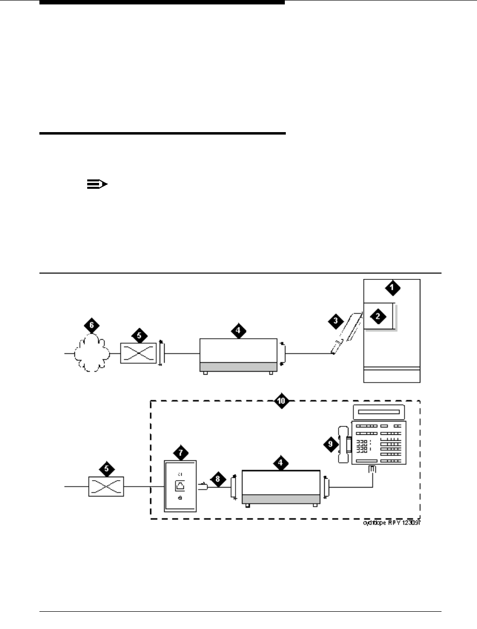
Figure 8 shows a typical connection from a digital line 2-wire DCP circuit pack
through two DCP extender devices. The DEFINITY Extender Switch Module
System Administrator’s Guide contains additional information.
Figure 8. Typical DCP extender connections
1. Avaya™ Media Server/Gateway
2. TN2181 or TN2224B circuit pack
3. 25-pair cable
4. DCP extender
5. Main distribution frame (MDF)
6. Public switched telephone network (PSTN)
7. 103A or modular wall jack
8. Modular line cord
9. DCP telephone (Such as 8410D,
8405, or 8434)
10. Remote work location
Extenders for 2-wire DCP endpoints
555-233-116
46 Issue 4 October 2002
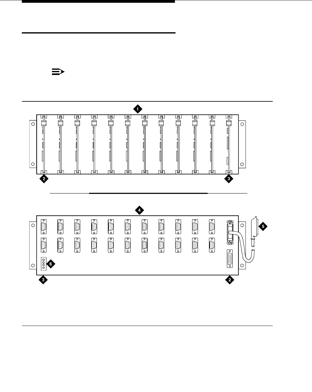
DCP extender, rack mount
Figure 9 shows a typical rack mount (multi-mount) DCP extender. Connections
from either a digital line 17-port 2-wire DCP circuit pack or a digital line 24-port
2-wire DCP circuit pack, are made through two DCP extender devices.
NOTE:
2-wire DCP extenders are not currently supported on G700 Media Gateway
configurations.
Figure 9. Typical DCP extender connections
1. Front of rack mount assembly
2. First circuit pack in slot 1 (“A”)
3. Slot 12 (“L”)
4. Rear of rack mount assembly
5. 25-pair connector to the MDF and the digital
line circuit packs
6. Power connector
h2dferm PDH 100796

Issue 4 October 2002 47555-233-116
4
Data modules and asynchronous data
units
Data modules connect peripheral equipment to the Avaya Media Server or
Gateway or the Avaya S8100 Media Server with a CMC1 Media Gateway
(DEFINITY ONE). Data modules convert between the RS-232 communications
protocol used by peripherals and the digital communications protocol (DCP).
Possible peripherals include AUDIX adjunct equipment and terminals, serial
printers, customer-supplied terminals and host computers, call detail recording
(CDR) devices, and pooled modems.
NOTE:
Data modules, PGATE boards, printers connected through data modules,
SATs connected through data modules, and anything related to the X.25
connectivity protocol are not supported on the S8300 or S8700 Media
Server platforms.
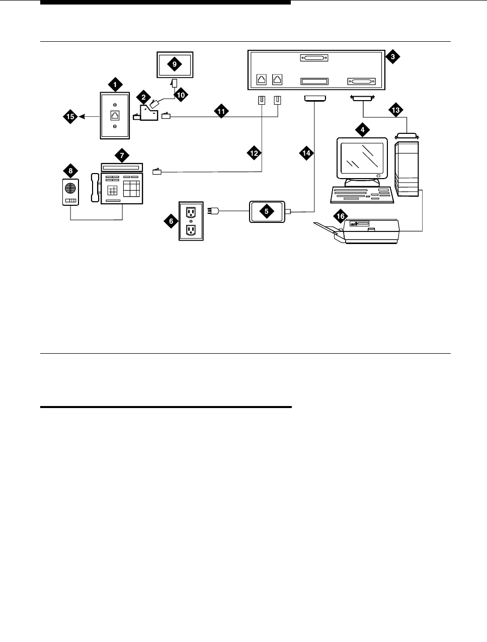
The following data modules are described in this chapter, and Figure 10 shows
typical data-module connections.
■7400A/B/C/D
■8400B
■ExpressRoute 1000
■Asynchronous data units (ADU).
NOTE:
ISDN data modules, such as the 7500B, are not covered in this book. Refer
to Integrated Services Digital Network (ISDN) 7500B Data Module User’s
Manual, for detailed procedures. ISDN data modules connects DTE and
DCE equipment to the ISDN network using an RS-232 or V.35 interface and
an RS-377 automatic calling unit.

Data modules and asynchronous data units
555-233-116
48 Issue 4 October 2002
Understanding RS-232
communications
To install a data module, you have to set up the device to work with RS-232
devices.
NOTE:
Data modules, PGATE boards, printers connected through data modules,
SATs connected through data modules, and anything related to the X.25
connectivity protocol are not supported on the S8300 or S8700 Media
Server platforms.
The RS-232 communications protocol defines a communications link as a Data
Communications Equipment (DCE) device and a Data Terminal Equipment (DTE)
device connected by an RS-232 cable. The send and receive pins on DCE
equipment (pins 2 and 3) are reversed on DTE equipment, so that the DCE
transmit pin connects to the receive pin of the DTE and vice versa.
Generally, the term DCE is applied to devices that mediate between customer
equipment and the carrier or network. Such devices include modems, data
modules, and data units. DTE describes devices that provide a user interface for
data communications, such as dumb terminals and PCs. When configured as
DTE, data modules are used for asynchronous modem pooling. When configured
as DCE, data modules are analogous to modems in that they link a device such
as a terminal or PC (DTE) to DEFINITY.
To install a data module correctly, you identify the connected equipment as DCE
or DTE and do one of the following:
■Configure the modem for a DTE or DCE connection
■Install a null-modem converter
Detailed instructions are provided for each modem type, beginning on page 49.
Installation procedure
Issue 4 October 2002 49555-233-116
Figure 10. Typical connections to a data module
Installation procedure
To install a typical data module, you perform the following tasks:
1. Obtain required equipment
2. Set hardware options (must be completed before you administer or
physically connect the data module)
3. Connect data modules
4. Administer the data modules (can be completed either before or after you
physically connect the data module)
1. 103A connector or modular wall jack
2. 400B2 adapter
3. Rear of data module (7400B Shown)
4. Host computer
5. Data module power supply
6. Electrical outlet
7. Display telephone
8. S101A speakerphone
9. Auxiliary power supply for telephone
10. D7AP cord
11. D8W cord
12. Line to display telephone (D8W cord)
13. Data cable (EIA/RS-232)
14. Data-module power cable
15. To MDF and system cabinet
16. Printer
Phone Power Port 1
Port 2
Line
cydfnst RPY 070397

Data modules and asynchronous data units
555-233-116
50 Issue 4 October 2002
Obtain required equipment
To physically connect a data module to the system, you need the following parts.
■105C/D Isolating Data Interface (if connecting to a DC cabinet).
■EIA-232-D (RS-232-C) cable with a male connector (for the data module)
and the correct connector for the peripheral equipment.
The cable connects the PC to the data module.
■Null-modem converter (optional).
■V.35 cable with correct connectors (not required by all systems).
■D8W telephone cord.
The cord connects the data module’s LINE jack to the DEFINITY wall jack.
■DCP telephone and D8W cord (optional).
The D8W cord connects the telephone to the data module’s PHONE jack.
■Suitable auxiliary power supply if the optional telephone is installed (D7AP
power cord and 400B2 adapter in the US, international power supply, such
as the MSP-1, elsewhere).
You must have access to the administration console of the DEFINITY, either
through a terminal and keyboard or through a PC.
A breakout box for RS-232 interfaces may prove helpful in some cases. The RS-
232 breakout box helps you to identify the pin configuration of the RS-232
interface on the equipment you are trying to connect.
Set hardware options
Depending on the data module, you may have to set various configuration options
using hardware switches, software commands, or both. You must set the
hardware options before you administer or physically install the data module.
Setting 7400A data module hardware options
Most configuration options are controlled by commands entered on the front panel
of the 7400A. But you have to make hardware changes when you want to set up
the 7400A data-module for use in a modem pool or as a piece of data
communications equipment. In a modem-pool, the data module operates as data-
terminal equipment (DTE). In most other applications, it functions as data
communications equipment (DCE). You have to set the correct operating mode for
the data module before you can access the menus for the remaining configuration
tasks.

Set hardware options
Issue 4 October 2002 51555-233-116
To change the operating mode of the 7400A from DCE to DTE (or vice versa), you
change the position of a small circuit board (the Electronic Industries Association
connector board) inside the case. See Figure 11 and proceed as follows.
!WARNING:
Electrostatic discharge can severely damage sensitive electronic circuits.
Before handling any electronic hardware, be sure to wear a grounding wrist
strap or other static-dissipating device. Do not touch exposed circuitry or
semiconductor chips.
1. Unplug the data module from the power receptacle.
2. Remove the access panel on the top of the case by grasping the rear lip of
the panel and pulling sharply upward.
3. While facing the front of the data module, locate the small EIA connector
circuit board. It sticks up vertically, and a large, silver arrow on the main
circuit board points to it.
Figure 11. Data module mode selector
4. Note the three letters engraved in the upper lefthand corner of the EIA
connector board. Data modules ship from the factory with board inserted
with “DCE” in the upper left corner.
1. 7400A data module 2. EIA connector board (shown in DTE mode)
POWER TEST
NEXT/NO BACK ENTER/YES
7400A Data Module DATA
HOME
DTE
7400atop KLC 053096
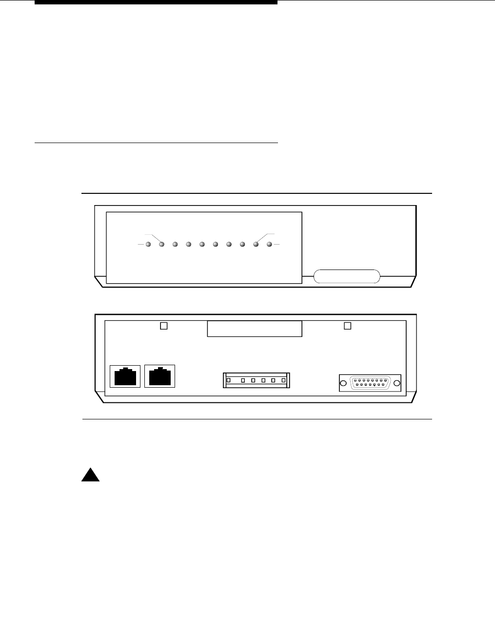
Data modules and asynchronous data units
555-233-116
52 Issue 4 October 2002
5. Use the DCE position to connect to DTE equipment. Use the DTE position
to connect to DCE equipment. To change the mode, remove the board by
grasping it and pulling it gently upward. Flip the board around, left to right,
and reinsert it in the socket so that the correct operating mode, DCE or
DTE, appears in the upper lefthand corner.
6. Snap the top cover onto the unit.
Setting 7400B data module hardware options
You configure the 7400B data module using DIP switches on the circuit card
inside the case. Figure 12 shows the front and rear of a 7400B data module.
To configure the 7400B data module, proceed as follows.
!WARNING:
Electrostatic discharge can severely damage sensitive electronic circuits.
Before handling any electronic hardware, be sure to wear a grounding wrist
strap or other static-dissipating device. Do not touch exposed circuitry or
semiconductor chips.
1. If you are not attaching a telephone to the data module, activating data
metering, or enabling busyout on the local loop, you can use the factory
default settings. The 7400B data module is already configured for your use.
Stop now.
POWER
TEST
DATA
METERING
7400B Data Module
AA CD RD SD TR OH
CHECK
SPEED
DATA
PORT 2
PORT 1
POWER
PHONE LINE
74
00
bRBP
03
2
596
Figure 12. 7400B data module
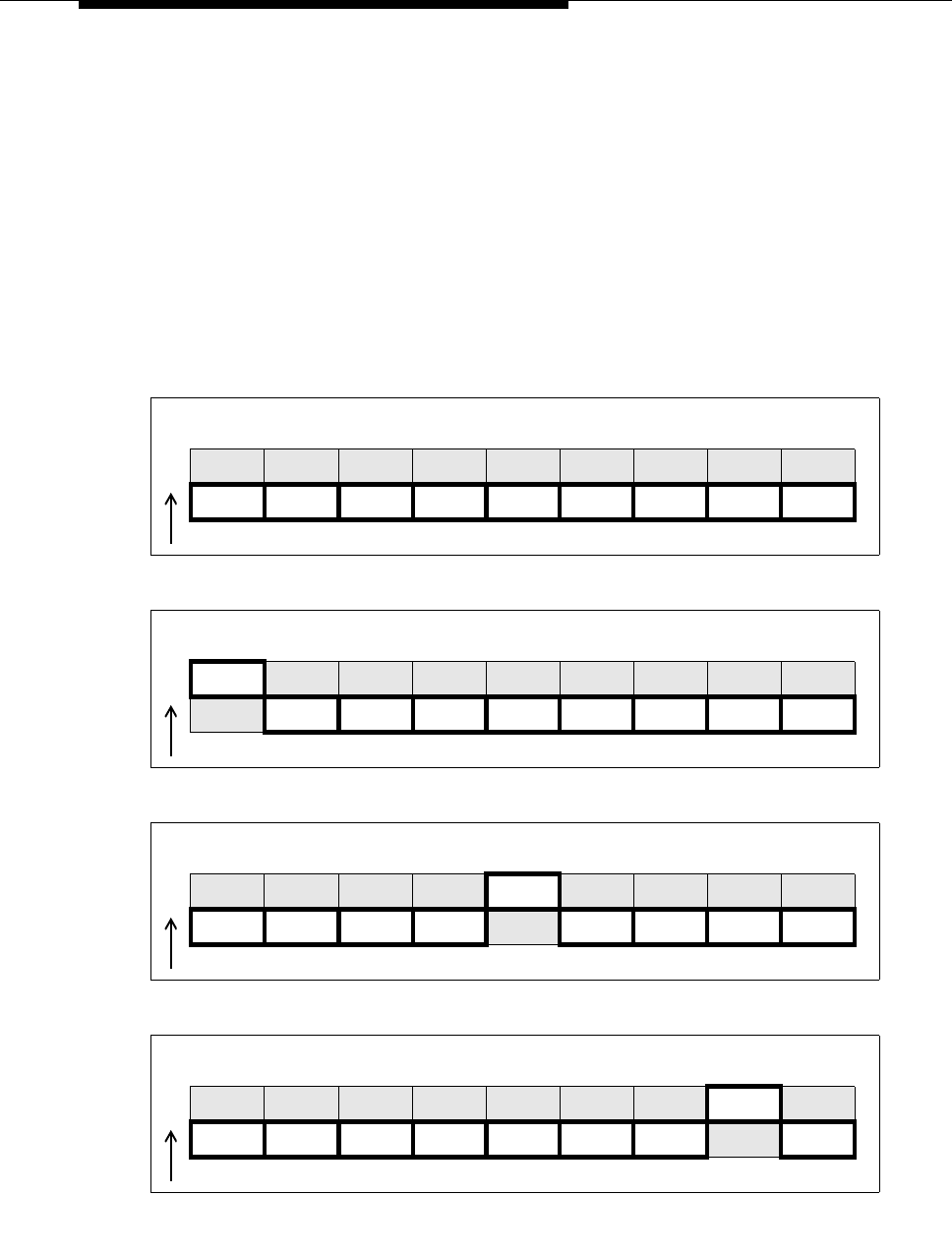
Set hardware options
Issue 4 October 2002 53555-233-116
2. Otherwise, remove the access panel on the top of the case by grasping the
rear lip of the panel and pulling sharply upward.
3. Locate the DIP switch block, a bank of tiny switches on the circuit board, in
the center of the opening.
DIP switches 1, 5, and 8 control the attached telephone (if any), data
metering, and loopback on local loop.
4. Set the switches for the combination of options that you need to enable,
using the chart below as a guide.
No telephone attached, data metering OFF, busyout on local loop OFF
(factory default settings)
O
N123456789
DOWN DOWN DOWN DOWN DOWN DOWN DOWN DOWN DOWN
Telephone attached, data metering OFF, busyout on local loop OFF
O
N123456789
UP
DOWN DOWN DOWN DOWN DOWN DOWN DOWN DOWN
No telephone attached, data metering ON, busyout on local loop OFF
O
N123456789
UP
DOWN DOWN DOWN DOWN DOWN DOWN DOWN DOWN
No telephone attached, data metering OFF, busyout on local loop ON
O
N123456789
UP
DOWN DOWN DOWN DOWN DOWN DOWN DOWN DOWN
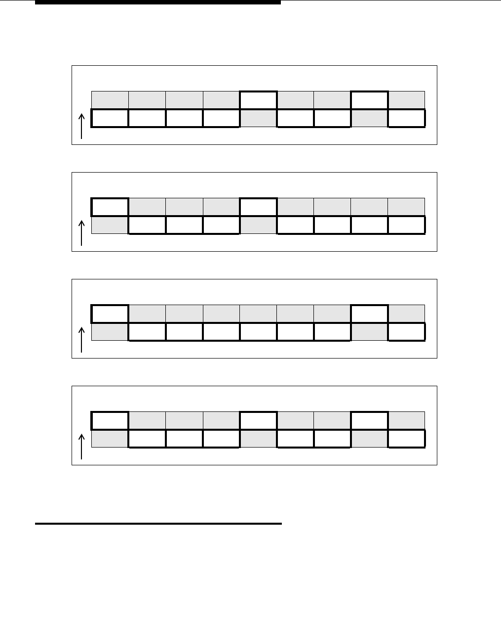
Data modules and asynchronous data units
555-233-116
54 Issue 4 October 2002
5. Replace the cover on the data module.
Connect data modules
To connect a single data module, follow the procedure in following section. To
connect multiple data modules, see Connecting multiple data modules to the
system.
No telephone attached, data metering ON, busyout on local loop ON
O
N123456789
UP UP
DOWN DOWN DOWN DOWN DOWN DOWN DOWN
Telephone attached, data metering ON, busyout on local loop OFF
O
N123456789
UP UP
DOWN DOWN DOWN DOWN DOWN DOWN DOWN
Telephone attached, data metering OFF, busyout on local loop ON
O
N123456789
UP UP
DOWN DOWN DOWN DOWN DOWN DOWN DOWN
Telephone attached, data metering ON, busyout on local loop ON
O
N123456789
UP UP UP
DOWN DOWN DOWN DOWN DOWN DOWN

Connect data modules
Issue 4 October 2002 55555-233-116
Connecting a single data module
!CAUTION:
You must install a 105D or 105C isolating data interface adapter when
connecting data modules to equipment in DC-powered cabinets.
Connect the data module to your house wiring or DEFINITY as follows.
1. Attach a D8W cable to the LINE port of the data module.
2. If you are going to attach a telephone to the data module
a. Attach a 400B2 adapter to the other end of the D8W cable.
b. Plug the adapter into a modular wall jack or 103A connector.
c. Plug a D7AP cord into the 400B2 adapter.
d. Plug the other end of the D7AP cord into the auxiliary power supply
for the telephone.
You must have a separate power supply for the telephone and for
the data module.
e. Attach a D8W cable to the PHONE port of the data module.
3. If you are not attaching a telephone, attach the D8W cable from the Line
port of the data module to a modular wall jack or 103A connector.
4. Attach the data-module power supply to the power connector on the back
of the data module, and plug the power supply into an AC electrical outlet.
5. Connect an RS-232 cable to the PORT 1 connector on the back of the data
module.
6. If the equipment includes a V.35 interface, plug a V.35 cable into the V.35
connector on the data module.
7. If the data module is a 7400B DCE-only device and if the other end of the
cable is connected to another DCE device, insert a null-modem adapter
between the data module and the RS-232 cable.
8. Connect the other end of the RS-232 cable to a serial (COM) port
connection on the data device (host computer, serial printer, modem, etc.).
9. Go to the configuration procedure for the data module you are using:
■Installation procedure
■Configuring the 7400B Data Module
■Configuring the 7400C HSL (high- speed link) data module
■Configuring the 7400D data module
■Configuring the 8400B Plus data module
■Configuring the ExpressRoute 1000 data module
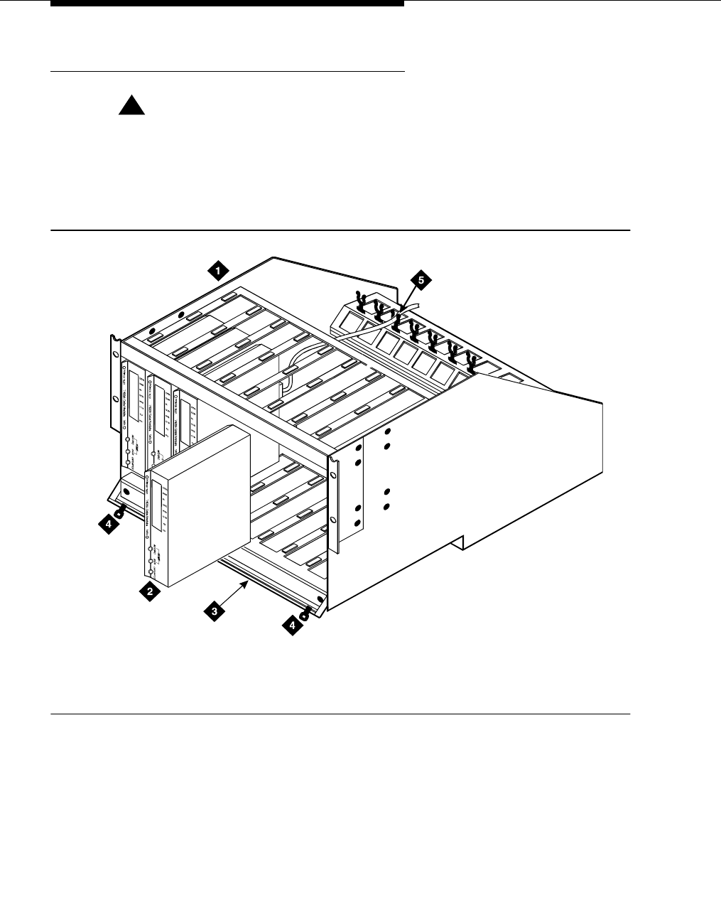
Data modules and asynchronous data units
555-233-116
56 Issue 4 October 2002
Connecting multiple data modules to the system
!CAUTION:
You must install a 105D or 105C isolating data interface adapter when
connecting data modules to equipment in DC-powered cabinets.
You install multiple data modules in a data mounting on the DEFINITY. A Z77A
data mounting can take up to 8 data modules. See Figure 13.
Figure 13. Z77A data mounting
Proceed as follows.
1. Set data-module hardware options before installing the hardware in the
mounting.
2. Release the horizontal retaining bar at the front of the data mounting by
pulling out the plungers at the left and right sides of the bar.
3. Pull the retaining bar out and down.
1. Z77A data mounting
2. Data module (7400A shown)
3. Retaining bar
4. Retaining bar plunger
5. Twist-lock cable retainers
z77a KLC 053096

Connect data modules
Issue 4 October 2002 57555-233-116
4. Connect the a 25-pin RS-232 cable to the 25-pin connector on the rear of
the data module.
5. Route the cable through the data mounting and through the twist-lock cable
retainer on the top of the data mounting.
6. Attach the other end of the RS-232 cable to DTE or DCE.
7. Insert the data module vertically into the data mounting. Be sure the display
is to the top of the data mounting.
8. Repeat steps 2 through 5 for each data module.
9. Return the horizontal retaining bar to its original position to secure the data
modules inside the data mounting.
10. Go to the configuration procedure for the data module you are using:
■Configuring the 7400A data module
■Configuring the 7400B Data Module
■Configuring the 7400C HSL (high- speed link) data module
■Configuring the 7400D data module
■Configuring the 8400B Plus data module
Configuring the 7400A data module
The 7400A is a full-duplex, asynchronous data module for use with Digital
Communications Protocol (DCP). It is designed for applications that do not require
integration of voice and data. It supports asynchronous connections at speeds up
to 19.2 Kbps through an EIA-232-D interface. Figure 14 represents the front and
back of the 7400A data module.
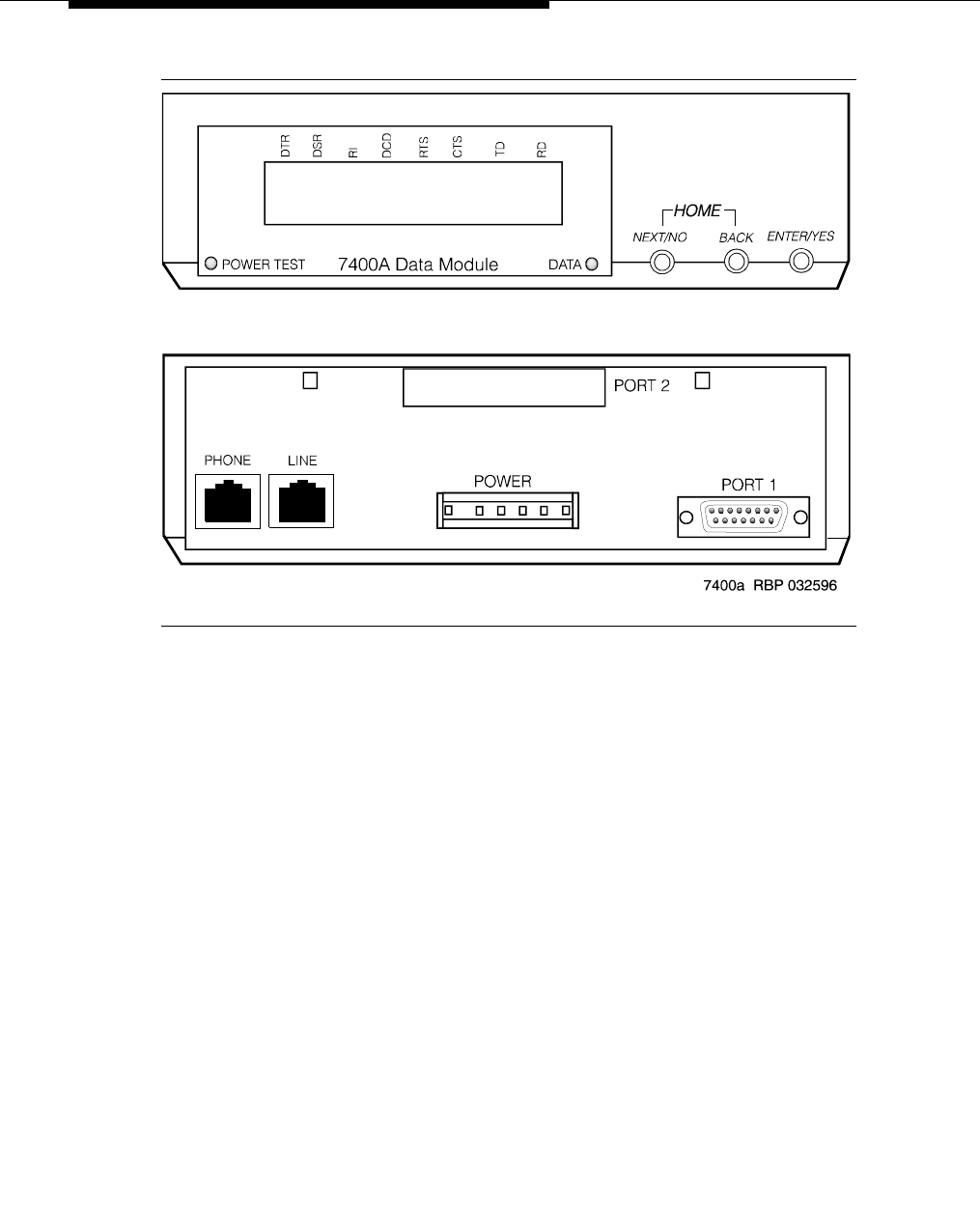
Data modules and asynchronous data units
555-233-116
58 Issue 4 October 2002
Figure 14. 7400A asynchronous data module
Using the 7400A menu system
On the 7400A, you select communications settings using the controls on the front
panel of the device. An LCD displays the configuration menus. You use the
NEXT/NO and BACK buttons to navigate through the menus and the ENTER/
YES button to select values.
Powering up the 7400A
When you power up the 7400A, the POWER TEST and DATA LEDs light up, and
the 7400A data module displays the HOME screen on the LCD. The figure below
represents a typical home screen. Dashes indicate a lead that is connected, ovals
a lead that is not.
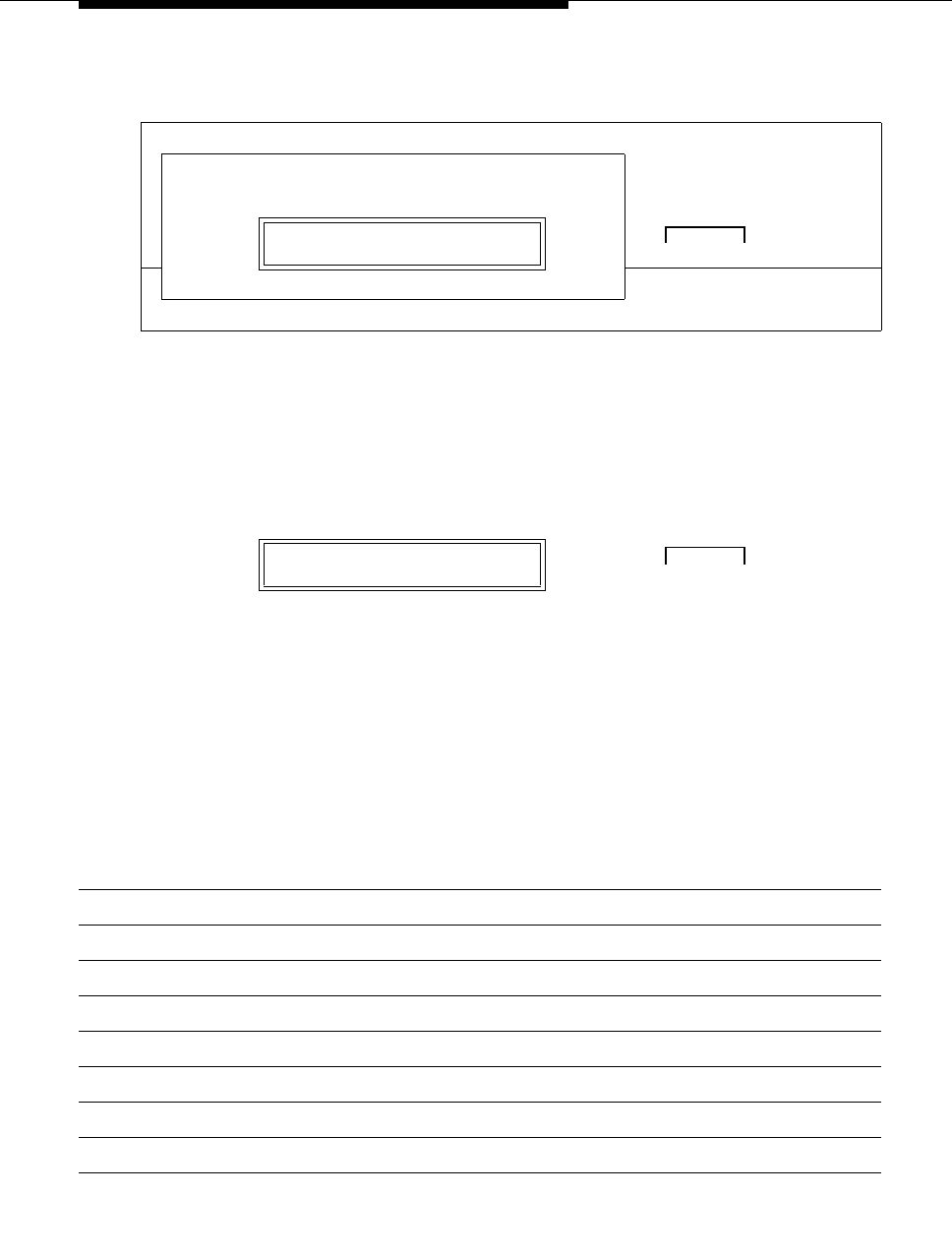
Connect data modules
Issue 4 October 2002 59555-233-116
Adjusting the control-panel display on the 7400A
1. Adjust the contrast of the display so that you can see it comfortably. Press
the ENTER/YES button. This steps you through the available contrast
settings.
7400A data module, EIA RS-232 interface circuits
The data module communicates with other equipment through a configurable, 25-
pin RS-232 serial interface. DCE and DTE operation use different sets of pins and
assign different functions to some of the same pins. To avoid confusion later on,
please take a moment to review the differences. See the table below (the pins
most discussed in subsequent sections have been emphasized).
D
T
R
D
S
RR
I
D
C
D
R
T
S
C
T
ST
DR
DHOME
POWER
TEST 0 0 —00 0—— DATA NEXT/NO BACK ENTER/YES
✹7400A Data Module ✹ ❍❍ ❍
0 0 —00 0—— DATA NEXT/NO BACK ENTER/YES
● ❍❍➜ ●
Push the button indicated by the arrow (➜)
Pin Name Function DCE DTE
1 — Not used ——
2 BA (TD) Transmitted Data Input Output
3 BB (RD) Received Data Output Input
4 CA (RTS) Request to Send Input Output
5 CB (CTS) Clear to Send Output Input
6 CC (DSR) Data Communication Equipment Ready Output Input
7 AB (SG) Signal Ground Common Common
8 CF (RLSD) Received Line Signal Detector Output Input
Continued on next page

Data modules and asynchronous data units
555-233-116
60 Issue 4 October 2002
* Circuits are not used for asynchronous operation. Outputs are clamped OFF and inputs are ignored.
Configuring the 7400A for data communications
equipment (DCE) applications
If you are not going to use the 7400A data module in a modem pool, proceed as
follows.
9 — Reserved for Testing +12 volts —
10 — Reserved for Testing -12 volts —
11 — Not used — —
12 CI Data Signal Rate Select (DCE Source) Output Input
13 CI2 Data Signal Rate Select 2 (DCE Source) — Input
14 — Not used — —
15 DB* Transmitter Signal Element Timing (DCE
Source) Output Input
16 — Not used — —
17 DD* Receiver Signal Element Timing (DCE
Source) Output Input
18 LL Local Loopback Input Output
19 CH2 Data Signal Rate Select 2 (DTE Source) — Output
20 CD (DTR) Data Terminal Equipment Ready Input Output
21 RL Remove Loopback Input Output
22 CE (RI) Ring Indicator Output Input
23 CH Data Signal Rate Select (DTE Source) Input Output
24 DA* Transmit Signal Element Timing (DTE
Source) Input Output
25 TM Test Mode Output Input
Pin Name Function DCE DTE
Continued on next page

Connect data modules
Issue 4 October 2002 61555-233-116
Setting interface options on 7400A DCE
1. To access the menus, press the NEXT/NO button.
2. When the SET OPTIONS? prompt appears on the LCD. Press the NEXT/
NO button.
3. The VIEW OPTIONS? prompt appears. Press the NEXT/NO button.
You will return to the options menus in a minute. But first you must select a
command interface for the data module.
4. The SET INTERFACE? prompt appears. Press the ENTER/YES button.
A series of INT = InterfaceType? prompts appears.
00—00 0—— DATA NEXT/NO BACK ENTER/YES
● ❍❍➜ ●
Push the button indicated by the arrow (➜)
SET OPTIONS? DATA NEXT/NO BACK ENTER/YES
●➜ ● ❍ ❍
Push the button indicated by the arrow (➜)
VIEW OPTIONS? DATA NEXT/NO BACK ENTER/YES
●➜ ● ❍ ❍
Push the button indicated by the arrow (➜)
SET INTERFACE? DATA NEXT/NO BACK ENTER/YES
● ❍❍➜ ●
Push the button indicated by the arrow (➜)

Data modules and asynchronous data units
555-233-116
62 Issue 4 October 2002
5. For each prompt, if you want to select the interface, press the ENTER/YES
button or, if you want a different interface, press the NEXT/NO button.
a. Enable the answer-only interface if the data module must operate
without any kind of external control:
b. Enable the AT-command interface if users need to control the data
module remotely, using a dial-up connection and Hayes-compatible
modem commands:
c. Enable the keyboard-dial interface if users need to control the data
module interactively, from a terminal:
After you select an interface, the data module runs a self-test and returns
to the HOME screen.
INT=ANS ONLY? DATA NEXT/NO BACK ENTER/YES
● ❍❍ ❍
Select an option (NEXT/NO or ENTER/YES)
INT = AT COM? DATA NEXT/NO BACK ENTER/YES
● ❍❍ ❍
Select an option (NEXT/NO or ENTER/YES)
INT = KYBD DIAL? DATA NEXT/NO BACK ENTER/YES
● ❍❍ ❍
Select an option (NEXT/NO or ENTER/YES)
D
T
R
D
S
RR
I
D
C
D
R
T
S
C
T
ST
DR
DHOME
POWER
TEST 00—00 0—— DATA NEXT/NO BACK ENTER/YES
✹7400A Data Module ✹ ❍❍ ❍

Connect data modules
Issue 4 October 2002 63555-233-116
Setting speed options on 7400A DCE
1. Press the NEXT/NO button to continue with the setup procedure.
2. The SET OPTIONS? prompt appears on the LCD. Press the ENTER/YES
button.
A series of SET number SPEED? prompts appears.
3. Press the NEXT/NO button until you see the SET 9600 SPEED? prompt.
Then press the ENTER/YES button.
Most DEFINITY connections operate at the 9600 speed.
4. The 9600 = ON? prompt appears. Press the ENTER/YES button.
5. The CONTINUE? prompt appears. Press the ENTER/YES button.
00—00 0—— DATA NEXT/NO BACK ENTER/YES
●➜ ● ❍ ❍
Push the button indicated by the arrow (➜)
SET OPTIONS? DATA NEXT/NO BACK ENTER/YES
● ❍❍➜ ●
Push the button indicated by the arrow (➜)
SET 9600 SPEED? DATA NEXT/NO BACK ENTER/YES
● ❍❍➜ ●
Push the button indicated by the arrow (➜)
9600=ON? DATA NEXT/NO BACK ENTER/YES
● ❍❍➜ ●
Push the button indicated by the arrow (➜)
CONTINUE? DATA NEXT/NO BACK ENTER/YES
● ❍❍➜ ●
Push the button indicated by the arrow (➜)

Data modules and asynchronous data units
555-233-116
64 Issue 4 October 2002
6. The SET 19200 SPEED? prompt appears. Press the NEXT/NO button.
7. If you selected the AT-command interface in the section ‘‘Setting interface
options on 7400A DCE’’, you are finished configuring the 7400A data
module.
Setting the automatic-answer feature on 7400A DCE
You can set up the 7400A data module to automatically answer calls or you can
have it ignore calls until an operator answers manually. Set up the data module for
automatic answering unless specifically directed to otherwise.
1. When the SET ANSWER? prompt appears, press the ENTER/YES button.
2. When the ANS = AUTO? prompt appears, if you want to enable automatic
answering, press the ENTER/YES button. Otherwise, press the NEXT/NO
button.
3. If you pressed NEXT/NO in the preceding step, the ANS —> MANUAL?
prompt appears. If you want to disable automatic answering, press the
ENTER/YES button. Otherwise, press the NEXT/NO button.
SET 19200 SPEED? DATA NEXT/NO BACK ENTER/YES
●➜ ● ❍ ❍
Push the button indicated by the arrow (➜)
SET ANSWER? DATA NEXT/NO BACK ENTER/YES
● ❍❍➜ ●
Push the button indicated by the arrow (➜)
ANS = AUTO? DATA NEXT/NO BACK ENTER/YES
● ❍❍ ❍
Select an option (NEXT/NO or ENTER/YES)
ANS —> MANUAL? DATA NEXT/NO BACK ENTER/YES
● ❍❍ ❍
Select an option (NEXT/NO or ENTER/YES)

Connect data modules
Issue 4 October 2002 65555-233-116
4. The CONTINUE? prompt appears. Press the ENTER/YES button.
Setting the break-disconnect option on 7400A DCE
This setting specifies the length of the BREAK signal, a string of 10 or more
spaces that tells the host that the user needs to interrupt operations. There are
three options: TRIPLE, LONG (the default), and NONE. Accept the default values,
unless otherwise instructed.
1. When the SET BREAK DISC? prompt appears, press the NEXT/NO
button to keep the default.
Configuring the RS-232 interface on 7400A DCE
You can set each pin of the RS-232 cable to meet the needs of specific
applications or connected equipment. however, in most cases, you can use the
defaults.
To set the EIA leads, proceed as follows:
1. When the SET LeadName LEAD? prompt appears, press the NEXT/NO
button to keep the default or the ENTER/YES button to make a change.
CONTINUE? DATA NEXT/NO BACK ENTER/YES
● ❍❍➜ ●
Push the button indicated by the arrow (➜)
SET BREAK DISC? DATA NEXT/NO BACK ENTER/YES
●➜ ● ❍ ❍
Push the button indicated by the arrow (➜)
SET LeadName LEAD? DATA NEXT/NO BACK ENTER/YES
●➜ ● ❍ ❍
Push the button indicated by the arrow (➜)

Data modules and asynchronous data units
555-233-116
66 Issue 4 October 2002
2. If you pressed the ENTER/YES button at the SET LeadName LEAD?
prompt, the LeadName -> ON? prompt appears. Press the ENTER/YES
button.
3. Repeat until all leads have been set.
Setting parity on 7400A DCE
Next you need to identify the type of parity coding that the data module should
expect. Parity is an error-detection scheme that is based on the value of a parity
bit in each unit of information. Four coding schemes are used: ODD, EVEN,
MARK, and SPACE. In odd-parity coding, the parity bit is set to 0 if the number of
1s in the information is odd, 1 if it is even. In even-parity coding, the parity bit is
set to 0 if the number of 1s in the information is even, 1 if it is odd. Mark-parity
coding always sets the parity bit to 1. Space-parity coding always sets the parity
bit to 0.
1. Accept the default value, unless otherwise instructed. When the SET
PARITY? prompt appears, press the NEXT/NO button to keep the default,
SPACE.
Enabling remote loopback testing on 7400A DCE
You can set the remote loopback option to GRANT or DENY.
1. Accept the default value, unless otherwise instructed. When the SET
REMOTE LOOP? prompt appears, press the NEXT/NO button to keep the
default, GRANT.
LeadName -> ON? DATA NEXT/NO BACK ENTER/YES
● ❍ ❍ ➜ ●
Push the button indicated by the arrow (➜)
SET PARITY? DATA NEXT/NO BACK ENTER/YES
●➜ ● ❍ ❍
Push the button indicated by the arrow (➜)
SET REMOTE LOOP? DATA NEXT/NO BACK ENTER/YES
●➜ ● ❍ ❍
Push the button indicated by the arrow (➜)

Connect data modules
Issue 4 October 2002 67555-233-116
Configuring the ring indicator on 7400A DCE
The ring-indicator (pin 22) setting can have either of two values: CYCLE or ON
(the default).
1. Accept the default values, unless otherwise instructed. When the SET RI
LEAD? prompt appears, press the NEXT/NO button to keep the default,
ON.
Enabling remote loopback on 7400A DCE
The remote-loopback setting (pin 21) can have either of two values: ON or OFF
(the default).
1. Accept the default values, unless otherwise instructed. When the SET RL
LEAD? prompt appears, press the NEXT/NO button to keep the default,
ON.
Setting the signals-disconnect (SIGLS DISC) option on 7400A DCE
The settings can have either of two values: ON (the default) or OFF.
Accept the default values, unless otherwise instructed.
1. When the SET SIGLS DISC? prompt appears, press the NEXT/NO button
to keep the default, ON.
SET RI LEAD? DATA NEXT/NO BACK ENTER/YES
●➜ ● ❍ ❍
Push the button indicated by the arrow (➜)
SET RL LEAD? DATA NEXT/NO BACK ENTER/YES
●➜ ● ❍ ❍
Push the button indicated by the arrow (➜)
SET SIGLS DISC? DATA NEXT/NO BACK ENTER/YES
●➜ ● ❍ ❍
Push the button indicated by the arrow (➜)

Data modules and asynchronous data units
555-233-116
68 Issue 4 October 2002
Enabling test mode on 7400A DCE
The test-mode (pin 25) setting can have either of two values: ON or OFF (the
default).
1. Accept the default values, unless otherwise instructed. When the SET TM
LEAD? prompt appears, press the NEXT/NO button to keep the default,
ON.
Exiting menus and saving changes on 7400A DCE
1. When the DONE? prompt appears, press the ENTER/YES button.
2. When the SAVE CHANGES? prompt appears, press the ENTER/YES
button.
Your changes are saved.
SET TM LEAD? DATA NEXT/NO BACK ENTER/YES
●➜ ● ❍ ❍
Push the button indicated by the arrow (➜)
DONE? DATA NEXT/NO BACK ENTER/YES
● ❍ ❍ ➜ ●
Push the button indicated by the arrow (➜)
SAVE CHANGES? DATA NEXT/NO BACK ENTER/YES
● ❍ ❍ ➜ ●
Push the button indicated by the arrow (➜)
CHANGES SAVED DATA NEXT/NO BACK ENTER/YES
● ❍ ❍ ➜ ●
Push the button indicated by the arrow (➜)
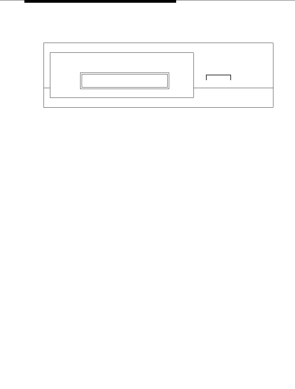
Connect data modules
Issue 4 October 2002 69555-233-116
You return HOME.
Checking DEFINITY administration on 7400A DCE
Check that the DEFINITY is administered to support the 7400A data module in the
DCE application as follows:
1. If necessary, return to the HOME display on the 7400A by pressing the
NEXT/NO and BACK buttons at the same time.
2. From the HOME display, press NEXT/NO until ANS/ORIG CALL? is
displayed, then press the ENTER/YES button.
3. If you see the message WAITING ... DISCONNECTED, the switch has not
been administered correctly.
4. If you see the message DIAL TONE followed by DISCONNECT CALL?,
the DEFINITY is correctly administered for the 7400A data module. Press
the ENTER/YES button to return to the menu.
The 7400A replies WAITING ... DISCONNECTED and returns to the ANS/
ORIG CALL? menu.
5. Return to the HOME display by pressing the NEXT/NO and BACK buttons
at the same time.
Configuring the 7400A for modem pooling (DTE) applications
From the HOME screen, proceed as follows.
D
T
R
D
S
RR
I
D
C
D
R
T
S
C
T
ST
DR
DHOME
POWER
TEST ———0———— DATA NEXT/NO BACK ENTER/YES
●7400A Data Module ● ❍❍ ❍
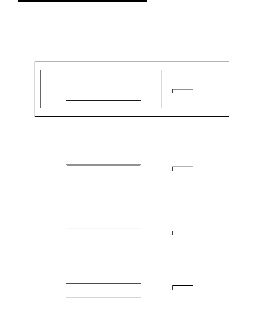
Data modules and asynchronous data units
555-233-116
70 Issue 4 October 2002
Setting speed options on 7400A DTE
1. To access the menus, press the NEXT/NO button.
2. When the SET OPTIONS? prompt appears on the LCD, press the ENTER/
YES button.
A series of SET number SPEED? prompts appears.
3. Press the NEXT/NO button until you see the SET 9600 SPEED? prompt.
Then press the ENTER/YES button.
Most DEFINITY connections operate at the 9600 speed.
4. The 9600 = OFF? prompt appears. Press the NEXT/NO button.
5. The 9600 —> ON? prompt appears. Press the ENTER/YES button.
D
T
R
D
S
RR
I
D
C
D
R
T
S
C
T
ST
DR
DHOME
POWER
TEST SET OPTIONS? DATA NEXT/NO BACK ENTER/YES
●7400A Data Module ● ➜ ● ❍ ❍
Push the button indicated by the arrow (➜)
SET 9600 SPEED? DATA NEXT/NO BACK ENTER/YES
● ❍❍➜ ●
Push the button indicated by the arrow (➜)
9600=OFF? DATA NEXT/NO BACK ENTER/YES
●➜ ● ❍ ❍
Push the button indicated by the arrow (➜)
9600 —> ON? DATA NEXT/NO BACK ENTER/YES
●❍❍➜ ●
Push the button indicated by the arrow (➜)

Connect data modules
Issue 4 October 2002 71555-233-116
6. The CONTINUE? prompt appears. Press the ENTER/YES button.
7. The SET 19200 SPEED? prompt appears. Press the NEXT/NO button to
keep the default.
8. The SET AT CONTROL? prompt appears. Press the ENTER/YES button
to enable Hayes-compatible modem commands. Press the NEXT/NO
button to accept the default (OFF).
Use the AT CONTROL setting to let users control the data module
remotely, using a dial-up connection.
9. If you enabled AT commands, the AT = OFF? prompt appears. Press the
NEXT/NO button.
CONTINUE? DATA NEXT/NO BACK ENTER/YES
●❍❍➜ ●
Push the button indicated by the arrow (➜)
SET 19200 SPEED? DATA NEXT/NO BACK ENTER/YES
●➜ ● ❍ ❍
Push the button indicated by the arrow (➜)
SET AT CONTROL? DATA NEXT/NO BACK ENTER/YES
● ❍ ❍ ❍
Select an option (NEXT/NO or ENTER/YES)
AT=OFF? DATA NEXT/NO BACK ENTER/YES
●➜ ● ❍ ❍
Push the button indicated by the arrow (➜)

Data modules and asynchronous data units
555-233-116
72 Issue 4 October 2002
10. If you enabled AT commands, the AT —> ON? prompt appears. Press the
ENTER/YES button.
11. If you enabled AT commands, the CONTINUE? prompt appears. Press the
ENTER/YES button.
Configuring the RS-232 interface on 7400A DTE
You can set each pin of the RS-232 cable to meet the needs of specific
applications, though in most cases, the defaults should work. For a list of pins and
leads, see Table 11 on page 73.
The Data Signal-Rate Select EIA leads—CI, CI2, CH, and CH2—of the RS-232
cable indicate the receive/transmit speeds that the data module can use. To set
the EIA signal-rate leads, proceed as follows:
1. From the HOME display, press NEXT/NO until SET OPTIONS? appears.
Then press the ENTER/YES button.
2. When the SET 300 SPEED? prompt appears, press NEXT/NO until SET
CI LEAD? appears. Then, using the table and instructions below as a
guide, start setting the leads.
AT —> ON? DATA NEXT/NO BACK ENTER/YES
● ❍❍➜ ●
Push the button indicated by the arrow (➜)
CONTINUE? DATA NEXT/NO BACK ENTER/YES
●❍❍➜ ●
Push the button indicated by the arrow (➜)
SET OPTIONS? DATA NEXT/NO BACK ENTER/YES
●❍❍ ➜ ●
Push the button indicated by the arrow (➜)
SET CI LEAD? DATA NEXT/NO BACK ENTER/YES
●❍❍ ➜ ●
Push the button indicated by the arrow (➜)

Connect data modules
Issue 4 October 2002 73555-233-116
Table 11. DTE-mode RS-232 signal-rate lead settings for the 7400A
3. When the SET CI LEAD? prompt appears, press the NEXT/NO button to
keep the default (OFF) or the ENTER/YES button to make a change.
4. If you pressed ENTER/YES in the preceding step and the CI LEAD = ON?
prompt appears, press the ENTER/YES button again to confirm your
selection.
5. When the SET CI2 LEAD? prompt appears, press the NEXT/NO button to
keep the default (OFF) or the ENTER/YES button to make a change.
CI CH CI2 CH2
If you selected AT control in an earlier step, set OFF OFF OFF OFF
You want only 1 data speed. OFF OFF OFF OFF
You want 2 data speeds. ON ON OFF OFF
You want only 3 or 4 data speeds. ON ON ON ON
SET CI LEAD? DATA NEXT/NO BACK ENTER/YES
●● ?❍● ?
Choose a button indicated by the question mark (?)
CI LEAD=ON? DATA NEXT/NO BACK ENTER/YES
●❍❍ ➜ ●
Push the button indicated by the arrow (➜)
SET CI2 LEAD? DATA NEXT/NO BACK ENTER/YES
●● ?❍● ?
Choose a button indicated by the question mark (?)

Data modules and asynchronous data units
555-233-116
74 Issue 4 October 2002
6. If you pressed ENTER/YES in the preceding step and the
CI2 LEAD = ON? prompt appears press the ENTER/YES button again to
confirm your selection.
7. When the SET CH LEAD? prompt appears, press the NEXT/NO button to
keep the default (OFF) or the ENTER/YES button to make a change.
8. If you pressed ENTER/YES in the preceding step and the CH LEAD = ON?
prompt appears, press the ENTER/YES button again to confirm your
selection.
9. If the SET CH2 LEAD? prompt appears, press the NEXT/NO button to
keep the default (OFF) or the ENTER/YES button to make a change.
CI2 LEAD=ON? DATA NEXT/NO BACK ENTER/YES
●❍❍ ➜ ●
Push the button indicated by the arrow (➜)
SET CH LEAD? DATA NEXT/NO BACK ENTER/YES
●● ?❍● ?
Choose a button indicated by the question mark (?)
CH LEAD=ON? DATA NEXT/NO BACK ENTER/YES
●❍❍ ➜ ●
Push the button indicated by the arrow (➜)
SET CH2 LEAD? DATA NEXT/NO BACK ENTER/YES
●● ?❍● ?
Choose a button indicated by the question mark (?)

Connect data modules
Issue 4 October 2002 75555-233-116
10. The maintenance-option EIA leads configure loopback testing for the data
module. You do not need to set any specific options. So, when the SET LL
LEAD? prompt appears, press the NEXT/NO and BACK buttons together
to return HOME.
11. When the SAVE CHANGES? prompt appears, press the ENTER/YES
button.
The CHANGES SAVED message flashes on screen, and you return to the
HOME screen. The data module is now configured.
Restoring factory defaults on 7400A DTE
If necessary, you can always revert to the factory default settings. From the
HOME screen, proceed as follows.
1. To access the menus, press the NEXT/NO button.
2. When the SET OPTIONS? prompt appears on the LCD, press the NEXT/
NO button.
SET LL LEAD? DATA NEXT/NO BACK ENTER/YES
● ➜ ● ➜ ● ❍
Push the button indicated by the arrow (➜)
SAVE CHANGES? DATA NEXT/NO BACK ENTER/YES
●❍❍ ➜ ●
Push the button indicated by the arrow (➜)
00—00 0—— DATA NEXT/NO BACK ENTER/YES
●➜ ● ❍ ❍
Push the button indicated by the arrow (➜)
SET OPTIONS? DATA NEXT/NO BACK ENTER/YES
●➜ ● ❍ ❍
Push the button indicated by the arrow (➜)

Data modules and asynchronous data units
555-233-116
76 Issue 4 October 2002
3. When the VIEW OPTIONS? prompt appears on the LCD, press the NEXT/
NO button.
4. When the TEST - RESET? prompt appears on the LCD, press the ENTER/
YES button.
5. When the DATA LOOPBACK? prompt appears on the LCD, press the
NEXT/NO button.
6. When the SELF-TEST? prompt appears on the LCD, press the NEXT/NO
button.
7. When the LOCAL LOOPBACK? prompt appears on the LCD, press the
NEXT/NO button.
VIEW OPTIONS? DATA NEXT/NO BACK ENTER/YES
●➜ ● ❍ ❍
Push the button indicated by the arrow (➜)
TEST - RESET? DATA NEXT/NO BACK ENTER/YES
● ❍ ❍ ➜ ●
Push the button indicated by the arrow (➜)
DATA LOOPBACK? DATA NEXT/NO BACK ENTER/YES
●➜ ● ❍ ❍
Push the button indicated by the arrow (➜)
SELF - TEST? DATA NEXT/NO BACK ENTER/YES
●➜ ● ❍ ❍
Push the button indicated by the arrow (➜)
LOCAL LOOPBACK? DATA NEXT/NO BACK ENTER/YES
●➜ ● ❍ ❍
Push the button indicated by the arrow (➜)
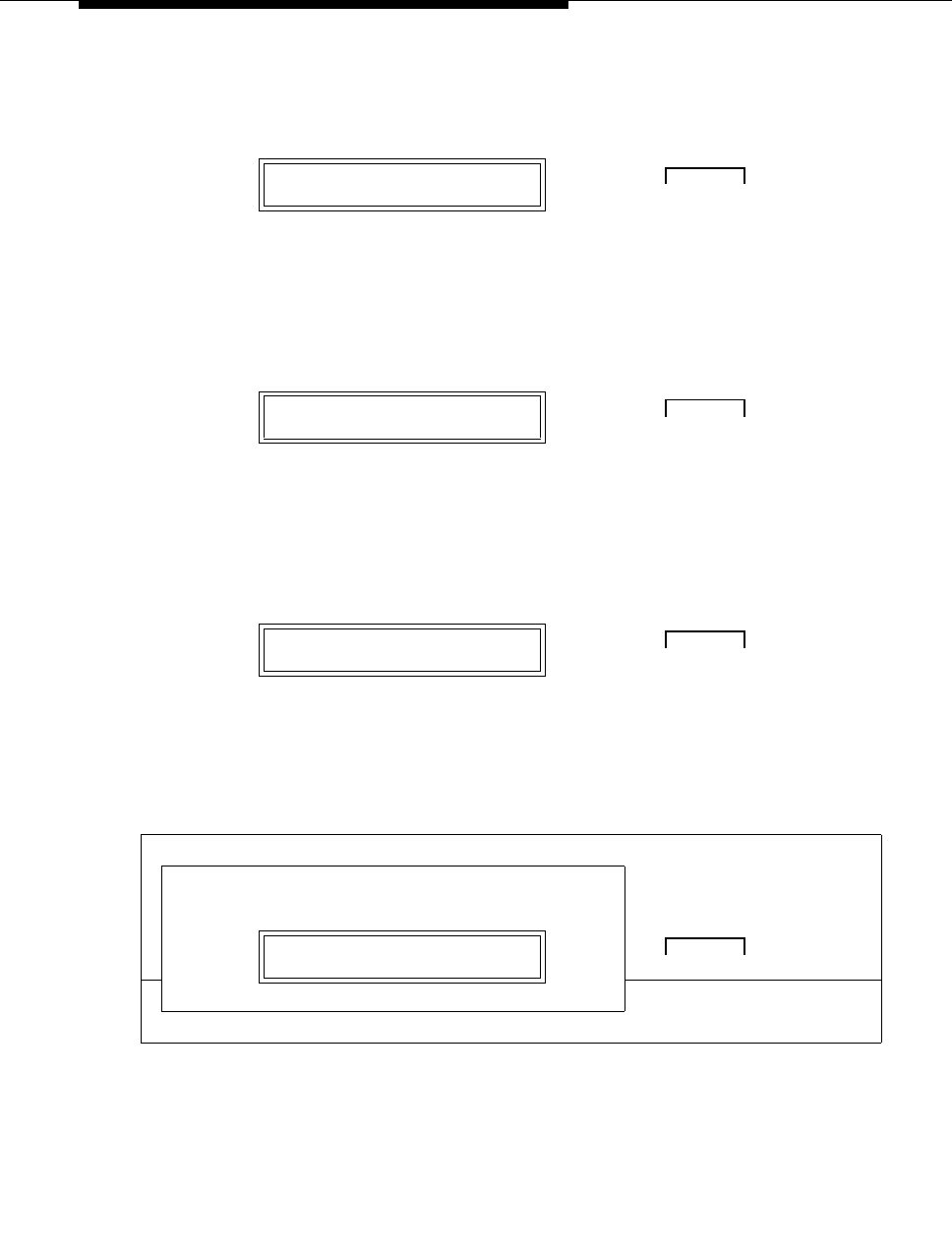
Connect data modules
Issue 4 October 2002 77555-233-116
8. When the LOCAL LOOP/ST? prompt appears on the LCD, press the
NEXT/NO button.
9. When the REMOTE LOOPBACK? prompt appears on the LCD, press the
NEXT/NO button.
10. When the RESET OPTIONS? prompt appears on the LCD, press the
ENTER/YES button.
The factory options are restored, and you return to the HOME screen.
LOCAL LOOP/ST? DATA NEXT/NO BACK ENTER/YES
●➜ ● ❍ ❍
Push the button indicated by the arrow (➜)
REMOTE LOOPBACK? DATA NEXT/NO BACK ENTER/YES
●➜ ● ❍ ❍
Push the button indicated by the arrow (➜)
RESET OPTIONS? DATA NEXT/NO BACK ENTER/YES
● ❍ ❍ ➜ ●
Push the button indicated by the arrow (➜)
D
T
R
D
S
RR
I
D
C
D
R
T
S
C
T
ST
DR
DHOME
POWER
TEST 00—00 0—— DATA NEXT/NO BACK ENTER/YES
●7400A Data Module ● ❍❍ ❍

Data modules and asynchronous data units
555-233-116
78 Issue 4 October 2002
Configuring the 7400B Data Module
The factory default settings for the7400B data module are generally satisfactory.
But if you need to change them, you use a terminal device and the AT command
language commonly used by Hayes-compatible modems (7400B data modules
have no control buttons). While a full explanation of the Hayes command set is
beyond the scope of this book, the following sections sketch the basic processes
involved in changing the factory settings.
Installing required configuration equipment for the 7400B
Before you can enter AT configuration commands, you must first connect a
terminal or a PC with a keyboard, monitor, and terminal-emulation software to the
data module. Proceed as follows.
1. Connect one end of an RS-232 cable to an RS-232, serial-communications
port (often called a COM port) on the terminal or PC.
2. Connect the other end of the RS-232 cable to Port 1 of the data module
3. If you are using a PC, start your terminal emulation software.
Selecting command mode on the 7400B
When it is transmitting and receiving data, the 7400B data module is online, in
data mode. To configure the 7400B, you have to switch it to command mode.
Proceed as follows.
1. From the terminal keyboard, enter the escape sequence: +++
The data module enters command mode and displays the OK result code.
Displaying the current configuration on the 7400B
1. Enter at&v
Enabling automatic answering on the 7400B
1. Enter ats0=nnn
where nnn is a decimal number in the range 1-255.
Enabling remote operation on the 7400B
The exact configuration of any particular 7400B data module depends on what it
is being used for. Consult a list of Hayes-compatible AT commands to see what is
possible. The following is an example of a typical, custom configuration.

Connect data modules
Issue 4 October 2002 79555-233-116
The 7400B data module can be used at a remote site as a dedicated service
device to answer incoming data calls, send data to a remote end device, and then
hang up. For example, you might wish to provide access to a printer from a
remote site. The following is a typical command line you might use for setting up
this operation (spaces are used here for readability, but are not required):
1. at &c1 &d2 q1 s0=1 &w0 &y0
where:
■at puts the modem in command mode
■&C1 sets the Data Carrier Detect (DCD) circuit of the data module to
operate according to the EIA standard
■&D2 sets the data module to go on hook when an on-to-off transition
is detected on the Data Terminal Ready (DTR) input, disconnecting
the call
■Q1 turns off the result codes that would be the normal responses of
the data module to commands that it receives.
■S0=1 turns on the automatic answer feature and causes the data
module to answer an incoming data call on the first ring
■&W0 causes the current configuration to be stored in profile 0
■&Y0 selects the configuration stored in profile 0 to become the
current configuration each time the data module is powered on
Configuring the 7400B for remote administration
1. At the command prompt of your terminal-emulation software or terminal,
enter at&c1&d2&s1s0=1&w0&w1&y0
where:
■at puts the modem in command mode
■&c1 tells the modem to respond to DCD
■&d2 tells the modem to respond to DTR
■&s1 tells the modem to respond to DSR
■s0=1 tells the modem to auto answer on the first ring
■&w0 tells the modem to save changes in profile 0
■&w1 tells the modem to save changes in profile 1
■&y0 tells the modem to use profile0 after a power failure
Restoring factory defaults for the 7400B
1. Enter at&F
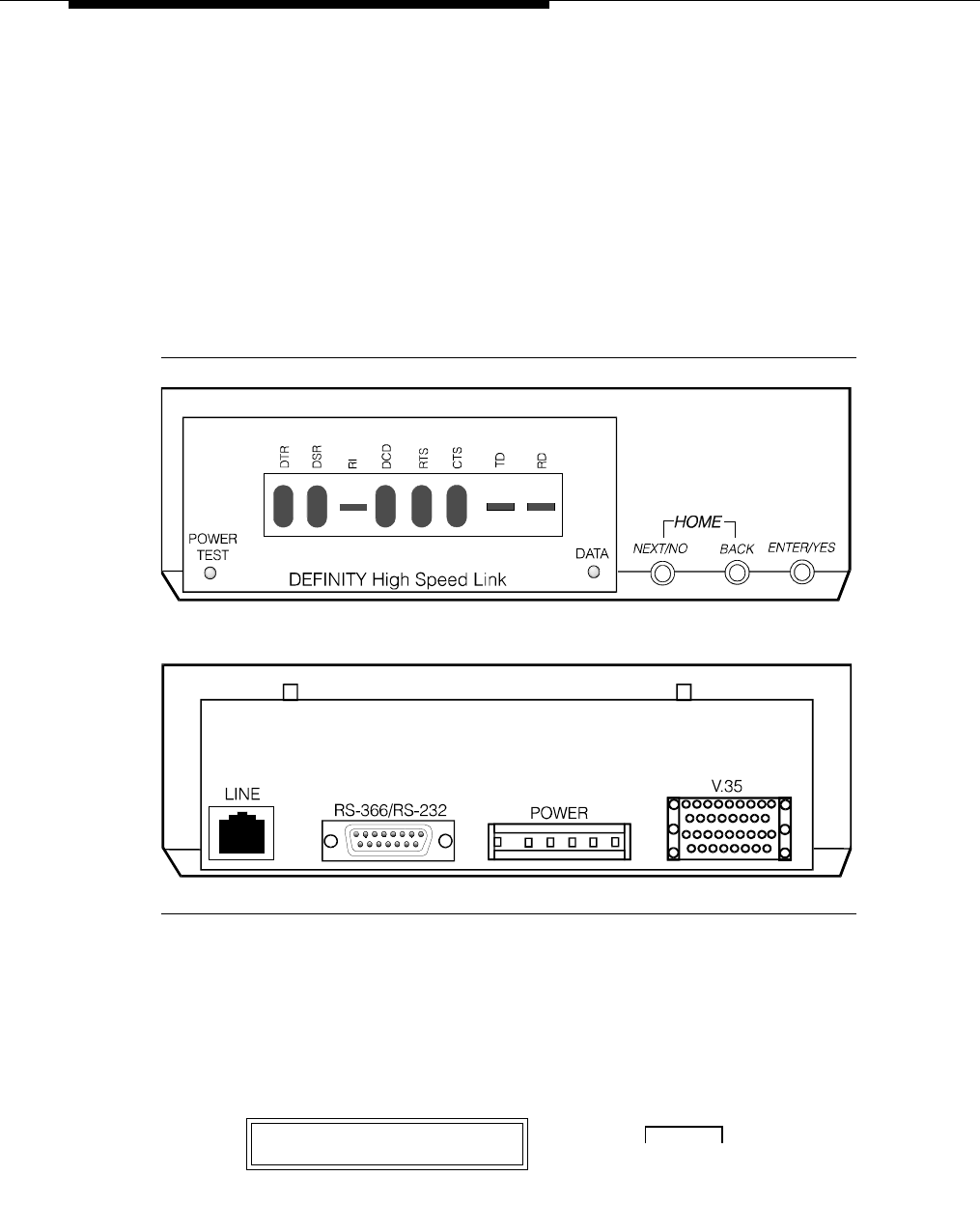
Data modules and asynchronous data units
555-233-116
80 Issue 4 October 2002
Exiting command mode on the 7400B
After configuring the 7400B, exit command mode, and put the data module back
online.
1. Enter O (capital O).
Configuring the 7400C HSL (high-
speed link) data module
Figure 15 shows the front and rear of a 7400C synchronous data module.
Figure 15. 7400C data module (high speed link)
Setting the data speed for the 7400C
Proceed as follows.
1. From the HOME screen, press the NEXT/NO button until SET DATA
OPTS? appears. Then press the ENTER/YES button.
SET DATA OPTS? DATA NEXT/NO BACK ENTER/YES
● ❍ ❍ ➜ ●
Push the button indicated by the arrow (➜)

Connect data modules
Issue 4 October 2002 81555-233-116
2. When SET SPEED? appears, press the ENTER/YES button.
The current transmission speed appears: SPEED = 56KBPS? (the
default) or SPEED = 64KBPS?
3. To keep the existing speed, press the ENTER/YES button.
4. To change the existing speed, press NEXT/NO.
When the SPEED ->NewSpeed? prompt appears, press the ENTER/YES
button.
5. The CONTINUE? prompt appears. Press the ENTER/YES button.
6. If you want to set any other options, skip to the following section.
SET SPEED? DATA NEXT/NO BACK ENTER/YES
● ❍ ❍ ➜ ●
Push the button indicated by the arrow (➜)
SPEED = 56 KBPS? DATA NEXT/NO BACK ENTER/YES
● ❍ ❍ ➜ ●
Push the button indicated by the arrow (➜)
SPEED = 56 KBPS? DATA NEXT/NO BACK ENTER/YES
●➜ ● ❍ ❍
Push the button indicated by the arrow (➜)
SPEED -> 64 KBPS? DATA NEXT/NO BACK ENTER/YES
● ❍ ❍ ➜ ●
Push the button indicated by the arrow (➜)
CONTINUE? DATA NEXT/NO BACK ENTER/YES
●❍❍➜ ●
Push the button indicated by the arrow (➜)

Data modules and asynchronous data units
555-233-116
82 Issue 4 October 2002
7. Otherwise, if you want to quit now, press NEXT/NO until DONE? appears.
Then press the ENTER/YES button.
8. When SAVE CHANGES? appears, press the ENTER/YES button again.
CHANGES SAVED appears, and the data module returns to the HOME
screen.
Setting other data options for the 7400C
You can usually use the default settings for all other options. However, two
exceptions are discussed below.
Selecting data inversion for 64-kbps, HDLC transmissions on restricted
facilities
Data inversion is available when you are transmitting at 64 kbps over restricted
facilities using HDLC-based protocols. Proceed as follows.
1. If you need compatibility with an ACCUNET MPDM, set DATA INVERSION
to ON using the menus and controls as described above, in ‘‘Setting the
data speed for the 7400C’’.
2. Otherwise, set DATA INVERSION to OFF.
3. Exit and save changes, as described above, in ‘‘Setting the data speed for
the 7400C’’.
Configuring the 7400C for a dedicated private line
The factory default settings assume that the data module connects to a switched,
dial-up line. Private lines are permanent, unswitched connections, so they have to
be specially configured. Proceed as follows.
1. Set the dialing method to MANUAL, using the menus and controls as
described above, in ‘‘Setting the data speed for the 7400C’’.
2. Set the answering mode (ANS) to AUTO.
3. Set the DTR lead to IGNORE.
DONE? DATA NEXT/NO BACK ENTER/YES
●❍❍➜ ●
Push the button indicated by the arrow (➜)
SAVE CHANGES? DATA NEXT/NO BACK ENTER/YES
●❍❍➜ ●
Push the button indicated by the arrow (➜)

Connect data modules
Issue 4 October 2002 83555-233-116
4. Set the DSR lead to ON.
5. Set PERMANENT CONNECTION to YES.
6. Exit and save changes, as described above, in ‘‘Setting the data speed for
the 7400C’’.
Configuring the 7400D data module
The 7400D data module is a converted 7400A used for synchronous data
transmission (see Figure 16). It is a direct replacement for the MPDM. You
configure the 7400D just as you would a 7400A, except that there is no SET
INTERFACE option (the 7400D is an answer-only device that cannot originate
calls). It supports DCE mode only. DTE modem-pooling is not supported. The
PHONE and PORT2 connectors are not used.
The following table lists recommended settings for a typical installation. For the
configuration procedure, see the subsequent sections.
Recommended settings for typical configurations
The table below summarizes the recommended configuration values for the
7400D data module. The procedures for setting these values follow.
Options CMS settings DCS settings
300 OFF OFF
1200 OFF OFF
2400 OFF OFF
4800 OFF OFF
9600 ON (OFF for R8r) ON
19200 OFF (ON for R8r) OFF
ANSWER AUTO AUTO
CI OFF ON
CH LEAD OFF OFF
CTS LEAD NORMAL NORMAL
DCD LEAD NORMAL ON
DSR LEAD NORMAL ON
DTR DETECT 50 MSEC 50 MSEC
DTR LEAD FOLLOW IGNORE
Continued on next page
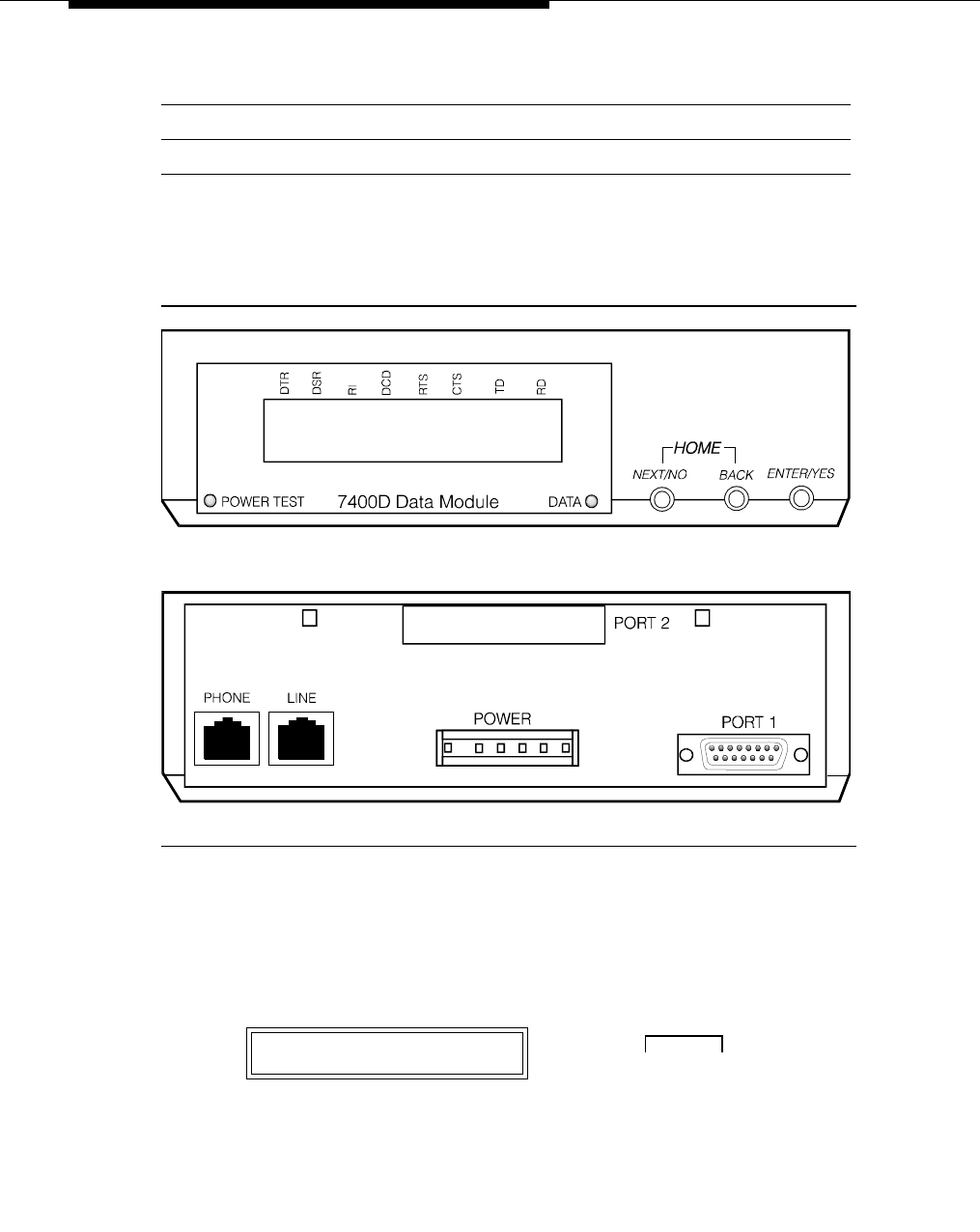
Data modules and asynchronous data units
555-233-116
84 Issue 4 October 2002
Figure 16. 7400D data module
Accessing the menus of the 7400D
You configure the 7400D from a set of menus.
1. To access the menus, press the NEXT/NO button.
RI LEAD ON ON
SIGLS DISC ON ON
TM LEAD OFF OFF
00—00 0—— DATA NEXT/NO BACK ENTER/YES
●➜ ● ❍ ❍
Push the button indicated by the arrow (➜)
Options CMS settings DCS settings
Continued on next page

Connect data modules
Issue 4 October 2002 85555-233-116
2. When the SET OPTIONS? prompt appears on the LCD. Press the NEXT/
NO button.
3. The VIEW OPTIONS? prompt appears. Press the NEXT/NO button.
Setting speed options for the 7400D
The data speed depends on the exact application, but most require 9600 bps or,
less commonly, 19200.
1. Press the NEXT/NO button to continue with the setup procedure.
2. The SET OPTIONS? prompt appears on the LCD. Press the ENTER/YES
button.
A series of SET number SPEED? prompts appears.
SET OPTIONS? DATA NEXT/NO BACK ENTER/YES
●➜ ● ❍ ❍
Push the button indicated by the arrow (➜)
VIEW OPTIONS? DATA NEXT/NO BACK ENTER/YES
●➜ ● ❍ ❍
Push the button indicated by the arrow (➜)
00—00 0—— DATA NEXT/NO BACK ENTER/YES
●➜ ● ❍ ❍
Push the button indicated by the arrow (➜)
SET OPTIONS? DATA NEXT/NO BACK ENTER/YES
● ❍❍➜ ●
Push the button indicated by the arrow (➜)

Data modules and asynchronous data units
555-233-116
86 Issue 4 October 2002
3. Press the NEXT/NO button until you see the SET yourSpeed SPEED?
prompt. Then press the ENTER/YES button.
4. Press the NEXT/NO button until you see the yourSpeed=ON? prompt.
Then press the ENTER/YES button.
5. If the CONTINUE? prompt appears, press the ENTER/YES button.
Setting the automatic-answer feature on the 7400D
You can set up the 7400D data module to automatically answer calls, or you can
have it ignore calls until an operator answers manually. Set up the data module for
automatic answering unless specifically directed to otherwise.
1. When the SET ANSWER? prompt appears, press the ENTER/YES button.
SET yourSpeed SPEED? DATA NEXT/NO BACK ENTER/YES
● ❍❍➜ ●
Push the button indicated by the arrow (➜)
yourSpeed=ON? DATA NEXT/NO BACK ENTER/YES
● ❍❍➜ ●
Push the button indicated by the arrow (➜)
CONTINUE? DATA NEXT/NO BACK ENTER/YES
● ❍❍➜ ●
Push the button indicated by the arrow (➜)
SET ANSWER? DATA NEXT/NO BACK ENTER/YES
● ❍❍➜ ●
Push the button indicated by the arrow (➜)

Connect data modules
Issue 4 October 2002 87555-233-116
2. When the ANS = AUTO? prompt appears, press the ENTER/YES button
for most applications.
Configuring the RS-232 interface of the 7400D
From the front panel, you can set each pin of the RS-232 cable to meet the needs
of specific applications, though in most cases, the settings below should work.
1. When the SET CI LEAD? prompt appears, press the ENTER/YES button.
2. Press the NEXT/NO button until you see the CI = correctSetting? or CI ->
correctSetting? prompt. Then press the ENTER/YES button.
3. When the CONTINUE? prompt appears, press the ENTER/YES button.
4. When the SET CH LEAD? prompt appears, press the ENTER/YES button.
ANS = AUTO? DATA NEXT/NO BACK ENTER/YES
● ❍❍➜ ●
Push the button indicated by the arrow (➜)
SET CI LEAD? DATA NEXT/NO BACK ENTER/YES
● ❍❍➜ ●
Push the button indicated by the arrow (➜)
CI = correctSetting?DATA NEXT/NO BACK ENTER/YES
● ❍ ❍ ➜ ●
Push the button indicated by the arrow (➜)
CONTINUE? DATA NEXT/NO BACK ENTER/YES
●❍❍ ➜ ●
Push the button indicated by the arrow (➜)
SET CH LEAD? DATA NEXT/NO BACK ENTER/YES
● ❍❍➜ ●
Push the button indicated by the arrow (➜)

Data modules and asynchronous data units
555-233-116
88 Issue 4 October 2002
5. Press the NEXT/NO button until you see the CH = correctSetting? or CH -
> correctSetting? prompt. Then press the ENTER/YES button.
6. When the CONTINUE? prompt appears, press the ENTER/YES button.
7. When the SET CTS LEAD? prompt appears, press the ENTER/YES
button.
8. Press the NEXT/NO button until you see the CTS = correctValue? or
CTS -> correctValue? prompt. Then press the ENTER/YES button.
9. When the CONTINUE? prompt appears, press the ENTER/YES button.
10. When the SET DCD LEAD? prompt appears, press the ENTER/YES
button.
CH = correctSetting?DATA NEXT/NO BACK ENTER/YES
●❍❍ ➜ ●
Push the button indicated by the arrow (➜)
SET CTS LEAD? DATA NEXT/NO BACK ENTER/YES
●❍❍ ➜ ●
Push the button indicated by the arrow (➜)
CTS -> correctValue?DATA NEXT/NO BACK ENTER/YES
●❍❍ ➜ ●
Push the button indicated by the arrow (➜)
SET DCD LEAD? DATA NEXT/NO BACK ENTER/YES
●❍❍ ➜ ●
Push the button indicated by the arrow (➜)

Connect data modules
Issue 4 October 2002 89555-233-116
11. Press the NEXT/NO button until you see the DCD = correctValue? or
DCD -> correctValue? prompt. Then press the ENTER/YES button.
12. When the CONTINUE? prompt appears, press the ENTER/YES button.
13. When the SET DSR LEAD? prompt appears, press the ENTER/YES
button.
14. Press the NEXT/NO button until you see the DSR = correctValue? or DSR
-> correctValue? prompt. Then press the ENTER/YES button.
15. When the CONTINUE? prompt appears, press the ENTER/YES button.
16. When the SET DTR DETECT? prompt appears, press the ENTER/YES
button.
DCD = correctValue?DATA NEXT/NO BACK ENTER/YES
●❍❍ ➜ ●
Push the button indicated by the arrow (➜)
SET DSR LEAD? DATA NEXT/NO BACK ENTER/YES
●❍❍ ➜ ●
Push the button indicated by the arrow (➜)
DSR -> correctValue?DATA NEXT/NO BACK ENTER/YES
●❍❍ ➜ ●
Push the button indicated by the arrow (➜)
SET DTR DETECT? DATA NEXT/NO BACK ENTER/YES
●❍❍ ➜ ●
Push the button indicated by the arrow (➜)

Data modules and asynchronous data units
555-233-116
90 Issue 4 October 2002
17. Press the NEXT/NO button until you see the DTR = correctValue MSEC?
or DTR -> correctValue MSEC? prompt. Then press the ENTER/YES
button.
18. When the CONTINUE? prompt appears, press the ENTER/YES button.
19. When you see the SET DTR LEAD? prompt, press the ENTER/YES
button.
20. Press the NEXT/NO button until the DTR = correctValue? or DTR -
>correctValue? prompt appears. Then press the ENTER/YES button.
21. When the CONTINUE? prompt appears, press the ENTER/YES button.
22. When the SET LL LEAD? prompt appears, press the NEXT/NO button to
skip this setting.
DTR = correctValue MSEC? DATA NEXT/NO BACK ENTER/YES
●❍❍ ➜ ●
Push the button indicated by the arrow (➜)
SET DTR LEAD? DATA NEXT/NO BACK ENTER/YES
●❍❍ ➜ ●
Push the button indicated by the arrow (➜)
DTR = correctValue?DATA NEXT/NO BACK ENTER/YES
● ❍ ❍ ➜ ●
Push the button indicated by the arrow (➜)
SET LL LEAD? DATA NEXT/NO BACK ENTER/YES
●➜ ● ❍ ❍
Push the button indicated by the arrow (➜)

Connect data modules
Issue 4 October 2002 91555-233-116
23. When the SET LL DETECT? prompt appears, press the NEXT/NO button
to skip this setting.
24. When the SET RI LEAD? prompt appears, press the ENTER/YES button.
25. Press the NEXT/NO button until the RI = correctValue? or RI -
>correctValue? prompt appears. Then press the ENTER/YES button.
26. When the CONTINUE? prompt appears, press the ENTER/YES button.
27. When the SET RL LEAD? prompt appears, press the NEXT/NO button to
skip this setting.
28. When the SET SIGLS DISC? prompt appears, press the ENTER/YES
button.
SET LL DETECT? DATA NEXT/NO BACK ENTER/YES
●➜ ● ❍ ❍
Push the button indicated by the arrow (➜)
SET RI LEAD? DATA NEXT/NO BACK ENTER/YES
●❍❍ ➜ ●
Push the button indicated by the arrow (➜)
SET RI = ON? DATA NEXT/NO BACK ENTER/YES
●❍❍ ➜ ●
Push the button indicated by the arrow (➜)
SET RL LEAD? DATA NEXT/NO BACK ENTER/YES
●➜ ● ❍ ❍
Push the button indicated by the arrow (➜)
SET SIGLS DISC? DATA NEXT/NO BACK ENTER/YES
●❍❍ ➜ ●
Push the button indicated by the arrow (➜)

Data modules and asynchronous data units
555-233-116
92 Issue 4 October 2002
29. Press the NEXT/NO button until the SIGLS DISC = correctValue? or
SIGLS DISC -> correctValue? prompt appears. Then press the ENTER/
YES button.
30. When the CONTINUE? prompt appears, press the ENTER/YES button.
31. When the SET TM LEAD? prompt appears, press the ENTER/YES button.
32. Press the NEXT/NO button until the TM = OFF? or TM -> OFF? prompt
appears, then press the ENTER/YES button.
33. When the DONE? prompt appears, press the ENTER/YES button.
34. When the SAVE CHANGES? prompt appears, press the ENTER/YES
button.
The CHANGES SAVED message flashes on screen, and you return to the
HOME screen. The data module is now configured.
SIGLS DISC = ON? DATA NEXT/NO BACK ENTER/YES
●❍❍ ➜ ●
Push the button indicated by the arrow (➜)
SET TM LEAD? DATA NEXT/NO BACK ENTER/YES
●❍❍ ➜ ●
Push the button indicated by the arrow (➜)
TM = OFF? DATA NEXT/NO BACK ENTER/YES
●❍❍ ➜ ●
Push the button indicated by the arrow (➜)
DONE? DATA NEXT/NO BACK ENTER/YES
●❍❍ ➜ ●
Push the button indicated by the arrow (➜)
SAVE CHANGES? DATA NEXT/NO BACK ENTER/YES
●❍❍ ➜ ●
Push the button indicated by the arrow (➜)
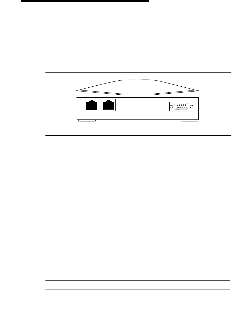
Connect data modules
Issue 4 October 2002 93555-233-116
Configuring the 8400B Plus data module
Figure 17 shows the rear of a 8400B Plus asynchronous data module. The unit
provides integrated voice and data communications over standard, 2-wire,
twisted-pair circuits within 2000 ft. of an DEFINITY. The unit can emulate a
Hayes-compatible interface for standard personal computer (PC) communication.
The options for the 8400B Plus are set from the rear panel interface.
Figure 17. 8400B Plus data module
Installing required configuration equipment for the 8400B
Before you can enter configuration commands, you must first connect a terminal
or a PC with a keyboard, monitor, and terminal-emulation software to the data
module. Proceed as follows.
1. Connect one end of an RS-232 cable to an RS-232, serial-communications
port (often called a COM port) on the terminal or PC.
2. Connect the other end of the RS-232 cable to Port 1 of the data module
3. If you are using a PC, start your terminal emulation software.
Selecting 8400B options
On the 8400B data module, all configuration options are enabled by default. You
configure the 8400B by disabling options with a code that you enter in a memory
register (S24) in the data module. Consult the table below, and perform the steps
that follow.
Table 12. Codes for disabling default settings of the 8400B data module
Default setting Disabling code
With Telephone 1
US Companding 2
Telephone Provides Dialing 4
Continued on next page
PHONE LINE
POWER
8400b RBP 041196

Data modules and asynchronous data units
555-233-116
94 Issue 4 October 2002
Proceed as follows.
1. Calculate an option-selection value using Table 12, ‘‘Codes for disabling
default settings of the 8400B data module’’. Add up the disabling codes for
all options that you wish to disable.
For example, if you turned off With Telephone, US Companding, Disable
Data Metering Feature, the selection code would be:
1 + 2 + 16 = 19
2. Check the current data-module setting by entering ATS24?.
3. If the current value does not match the selection value you calculated,
enter ATS24=nnn, where nnn is the selection value you calculated.
Configuring the ExpressRoute 1000 data module
You can substitute an ExpressRoute 1000 data module for the 8400B data
module. Both DCP and ISDN-BRI connections are possible. Figure 18 shows
typical connections.
!CAUTION:
In DC-powered cabinet installations, a 105C Isolator adapter is required
when connecting equipment to a data module.
Disable Data Metering Feature 16
Immediate Speakerphone Activation 32
Automatic Speakerphone Activation 64
Disable Busyout During Local Loopback Test 128
Table 12. Codes for disabling default settings of the 8400B data module
Default setting Disabling code
Continued on next page
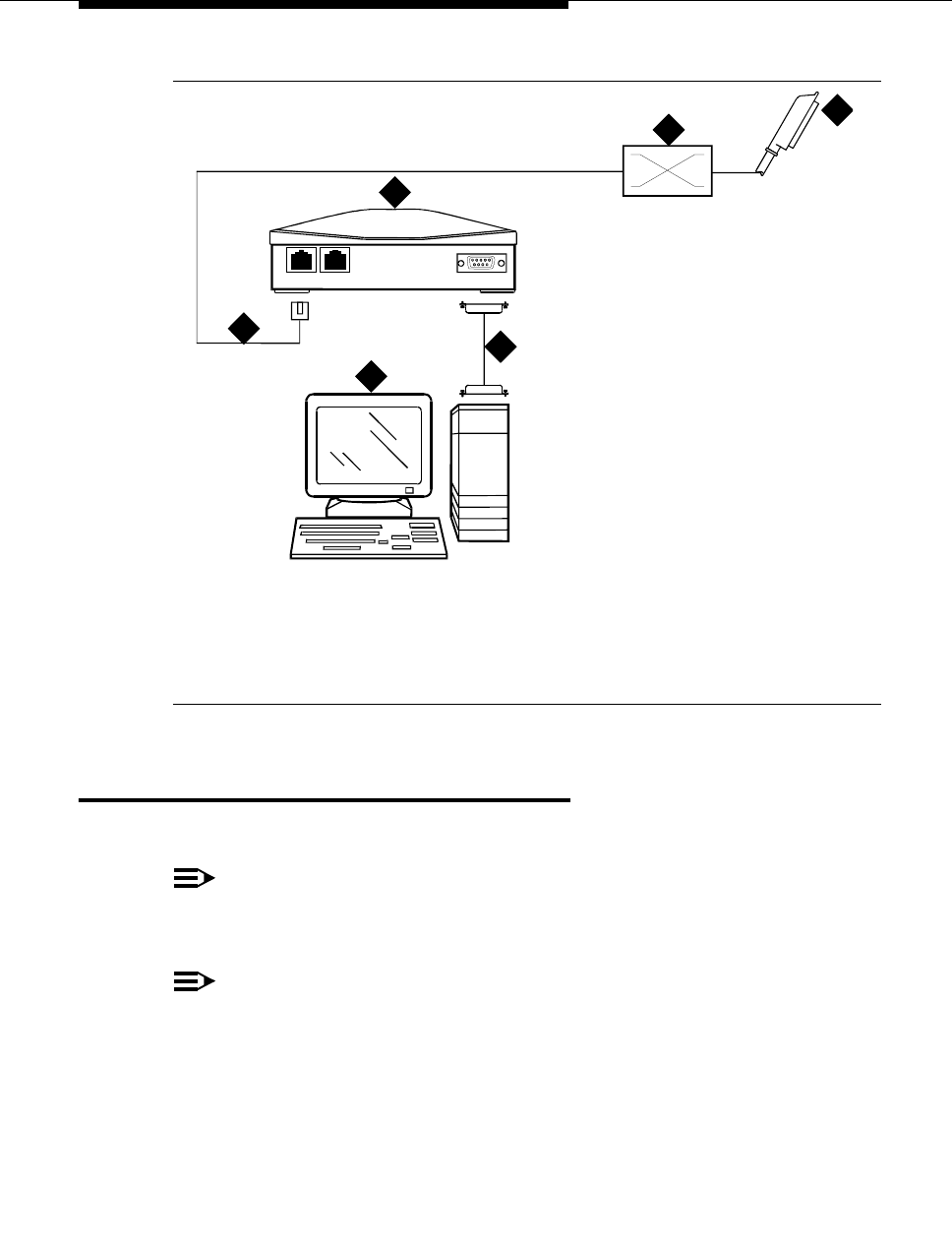
Administer the data modules
Issue 4 October 2002 95555-233-116
Figure 18. Typical ExpressRoute 1000 data module connections
Administer the data modules
You have to administer each data module that you attach to the system.
NOTE:
Only the basic procedure is covered here. For the full range of options, see
the Administrator’s Guide for Avaya MultiVantage Software.
NOTE:
Data modules, PGATE boards, printers connected through data modules,
SATs connected through data modules, and anything related to the X.25
connectivity protocol are not supported on the S8300 or S8700 Media
Server platforms.
1. Locate an available port. At the SAT, enter
list config port
1. To BRI circuit pack or DCP digital line
circuit pack
2. Main distribution frame (MDF)
3. ExpressRoute 1000 data module
4. PC administration terminal
5. Modular line cord
6. M25B (25-Pin RS-232) cable
cydf008 RPY 123097
PHONE LINE
POWER
1
2
3
4
56

Data modules and asynchronous data units
555-233-116
96 Issue 4 October 2002
Screen 1. Typical system-configuration listing
2. Locate an unassigned port on a suitable circuit pack, and make a note of
the corresponding port number.
The port number is the Board Number, UUCSS (where UU is the 2-digit
cabinet number, C is the single-character carrier identifier, and SS is the 2-
digit slot number) followed by the next 2-digit number, PP, in the sequence
in the Assigned Ports fields at the right side of the form: UUCSSPP.
For example, in the listing above, the next available port address for the
TN2181 digital line circuit pack would be 01A0503.
3. From the DEFINITY administration console, open a new data-module form
by typing
add data-module next
The system automatically assigns the next available extension number to
the data module.
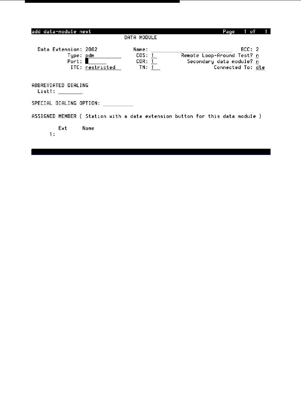
Administer the data modules
Issue 4 October 2002 97555-233-116
Screen 2. Typical data-module form
4. In the Port field, enter the seven-digit port address that you wrote down in
step 2, above.
5. If you installed a telephone on the data module, enter the extension
number and station name for this telephone in the ASSIGNED MEMBER
part of the form.
6. Press the F3 key to close the form and save the changes.
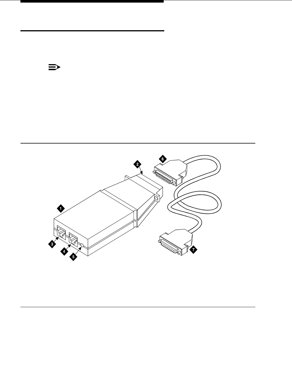
Data modules and asynchronous data units
555-233-116
98 Issue 4 October 2002
Asynchronous data units (ADU)
ADUs are used with Data Line circuit packs to connect peripherals, such as
printers, data terminals, fax equipment, and call-detail recording equipment to the
DEFINITY. Figure 19 shows a typical Z3A2 ADU assembly (without a cable).
NOTE:
Data modules, PGATE boards, printers connected through data modules,
SATs connected through data modules, and anything related to the X.25
connectivity protocol are not supported on the S8300 or S8700 Media
Server platforms.
■Add a female-to-male EIA-232 cable (shown) to make a Z3A1 ADU
assembly.
■Add a female-to-female EIA-232 cable (not shown) to make a Z3A4 ADU
assembly.
Figure 19. Z3A2 Asynchronous Data Unit (ADU)
Refer to the tables in Appendix A, ‘‘Connector and cable pinout charts’’, for the
pinouts of the TN726B data line circuit pack and TN2183 analog line circuit pack
(or equivalents) in the cabinet.
1. Z3A2 ADU
2. 25-pin male D-connector (EIA-232-D) to
DTE
3. Wall jack connector (to data line circuit pack
or analog line circuit pack or equivalent)
4. Telephone jack (to analog telephone)
5. Originate/disconnect jack
6. Female connector on EIA-232-D cable
7. Male connector on EIA-232-D cable
adu KLC 053196

Issue 4 October 2002 99555-233-116
5
External modems
The following section assumes that you are using one of the recommended
external modems. However, any locally obtained, type-approved external modem
should work. Contact your Avaya representative for more information.
Recommended modems include:
■‘‘Paradyne COMSPHERE 3715’’
■‘‘Paradyne COMSPHERE 3810 Plus and 3811 Plus’’
■‘‘Paradyne COMSPHERE 3910’’
■‘‘U.S. Robotics modems’’ (various models)
■‘‘Multi-Tech MT5634ZBA-USB’’ (for an S8300/G700 configuration)
Hardware required when configuring
modems
To configure many modems, you use the Hayes-compatible AT command set.
NOTE:
If your modem uses a USB connection, use the USB ports instead of the
serial port. Also, AT commands are not required, so you can skip this
section. Use the factory defaults.
Before you can enter AT configuration commands, you must first connect a
terminal or a PC with a keyboard, monitor, and terminal-emulation software to the
modem.
Proceed as follows:
1. Connect one end of an RS-232 cable to an RS-232, serial-communications
port (often called a COM port) on the terminal or PC.
2. Connect the other end of the RS-232 cable to the modem.
3. If you are using a PC, start your terminal emulation software.

External modems
555-233-116
100 Issue 4 October 2002
Paradyne COMSPHERE 3715
You configure COMSPHERE 3715 modems using the Hayes-compatible AT
commands common to many modems. For instructions on how to physically
connect the modem and enter the commands listed in the instructions below, see
the documentation that came with the modem.
Configuring the 3715 for CMS
The instructions below set up the modem for use in a Call Management System
(other configurations may work as well).
1. From the command line prompt of your terminal emulation software or
terminal, enter at&f.
This loads factory default configuration options into active memory. If all is
well, the modem replies OK.
2. Enter at%b9600.
This sets the data speed to 9600 kbps. If all is well, the modem replies OK.
3. Enter atq1&r0&S1\d1&w0.
This disables result codes, sets the RTS (Request To Send), DSR (Data
Set Ready), CTS (Clear To Send) signals action to standard RS-232
operation, and saves the changes to profile 0. If all is well, the modem
replies OK.
Configuring the 3715 for modem pooling
The instructions below set up the modem for use in a modem pool (other
configurations may work as well).
1. From the command line prompt of your terminal emulation software or
terminal, enter at &f.
This loads factory default configuration options into active memory. If all is
well, the modem replies OK.
2. Enter at m0 x7 y0 &s1 /d1.
If all is well, the modem replies OK.
3. Enter at e0 v0 c2=128 s7=60 f10=100 &w0 &y0.
If all is well, the modem replies OK.
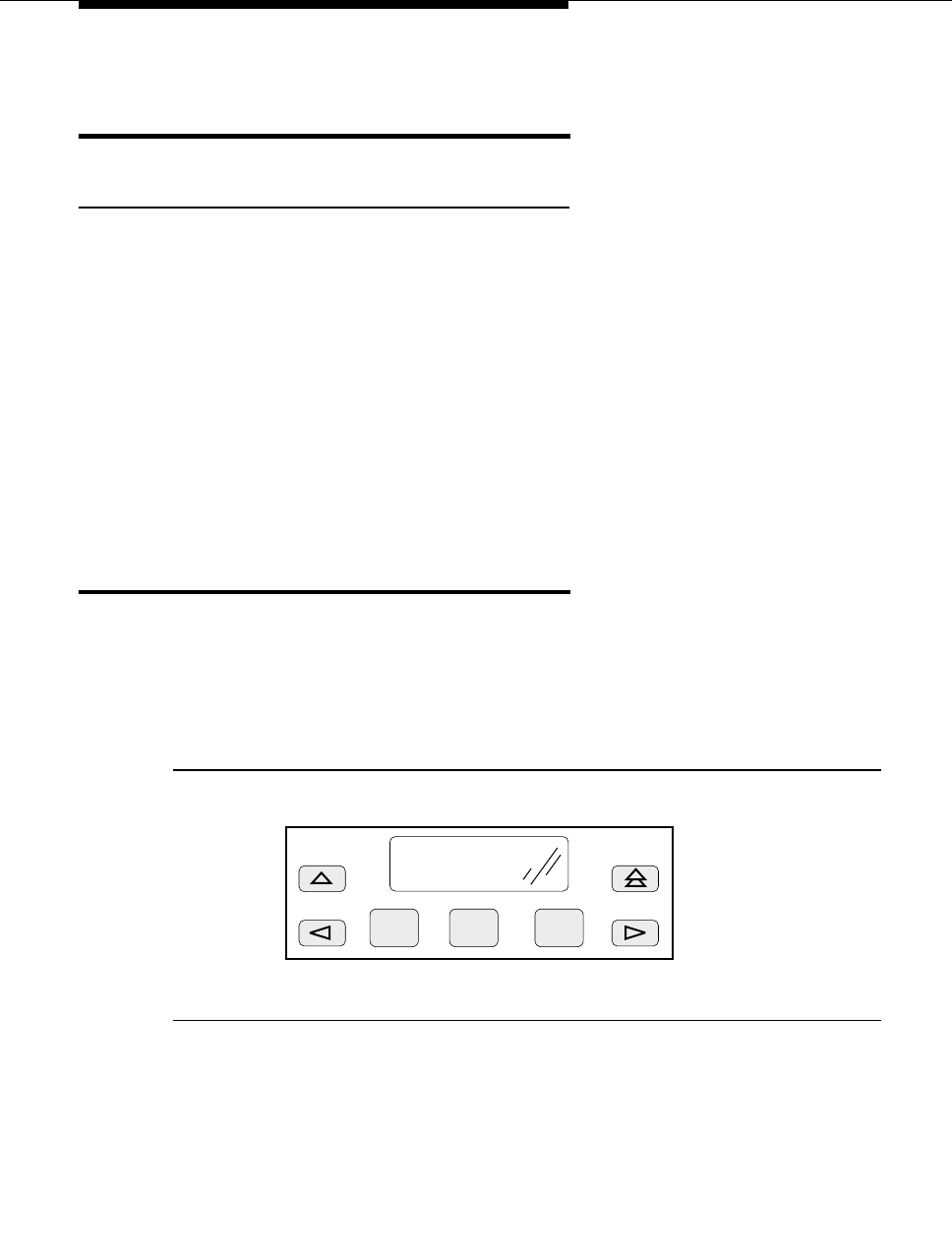
Paradyne COMSPHERE 3810 Plus and 3811 Plus
Issue 4 October 2002 101555-233-116
Paradyne COMSPHERE 3810 Plus and
3811 Plus
Configuring the 3810 Plus and 3811 Plus modems
1. Install the modem as described in the vendor’s documentation.
2. Attach a PC with terminal emulation software, as described in the vendor’s
documentation.
3. From the terminal, enter the following AT command string:
AT&F&D2&S4\D3S2=128x7V2S7=60S85=1
4. Then enter the following command string:
ATY0S10=100S78=2M0E0\N1&W
The modem is now configured.
Paradyne COMSPHERE 3910
You configure COMSPHERE 3910 modems using a front button panel (see
Figure 20) or Hayes-compatible AT commands. For instructions on how to
physically connect the modem and general configuration instructions, see the
documentation that came with the modem. This document describes configuring
the 3910 for particular, DEFINITY adjuncts.
Figure 20. COMPSPHERE 3910 modem, front panel
F1 F2 F3
Power On Selftst
Passed
modf3150 KLC 030899

External modems
555-233-116
102 Issue 4 October 2002
Configuring the 3910 for CMS
The COMSPHERE 3910 modem may be used as the Call Management System
(CMS) Remote Console Modem or as a device that provides serial connectivity to
CMS through the Network Terminal Server (NTS). The instructions below set up
the modem for use in CMS (other configurations may work as well).
Understanding the modem controls and displays
You control the modem by using the buttons on the front panel of the modem to
change menus and select menu items displayed on a small LCD screen. The
buttons do the following:
NOTE:
The arrow and function buttons described in this section are located
on the front panel of the modem, not on a PC keyboard or terminal.
■Single Up Arrow moves up one level in the menu tree.
■Double Up Arrow moves to the top level of the menu tree.
■Left Arrow moves to the previous choice at the current level of the menu
tree.
■Right Arrow moves to next choice at the current level of the menu tree.
■F1 selects the choice displayed above F1.
■F2 selects the choice displayed above F2.
■F3 selects the choice displayed above F3.
For our purposes, the on-screen prompt strap group indicates a collection of
related configuration settings.
Modem menus can be confusing because you only get to see one or two
headings or items at a time. The modem also has a limited set of command
words, so many of them have to be used more than once, and commands seem
to be repeating themselves. This can be confusing. To avoid missing a step,
check the values on the display after you enter a command, and make sure the
result agrees with that listed in the corresponding step in the instructions.

Paradyne COMSPHERE 3910
Issue 4 October 2002 103555-233-116
Creating an editable configuration set
It is generally easiest to configure the modem by starting from the default, factory
configuration. You then change only those settings that are different for a
DEFINITY installation.
Copying factory default settings
Make a copy of the default, factory configuration using the following procedure.
1. On the front panel of the COMSPHERE 3910, press the F2 button to select
Configure.
The Ld EditArea frm > prompt appears.
2. Press the right-arrow button four times.
The Factory menu item appears.
3. Press the F1 button to select Factory.
The Ld Fact Preset: > prompt appears.
4. Press the right-arrow button.
5. Press F2 to select Async_Dial.
6. Press F3 to select Save.
The Sav EditArea to > prompt appears.
7. Press F1 to save configuration changes to the Active(Saved) storage
area.
Since you are changing the active area to a new set of options— Factory/
Async_Dial—the modem automatically runs a power-on self-test. The
Idle:19.2 and Status Configure messages appear.
8. To return to the top-level menu at any time, press the double up-arrow
button.
Loading the copied default settings
Load the default settings so that you can edit them for use with CMS. Proceed as
follows.
1. On the front panel of the COMSPHERE 3910, press F2 to select
Configure.
The Ld EditArea frm > prompt appears.
2. Press the right-arrow button once.
The Active(Saved) prompt appears.
3. Press F1 to select Choose Function.
4. Press F1 to select Edit.
The Edit StrapGroup > prompt appears.

External modems
555-233-116
104 Issue 4 October 2002
Configuring the DTE interface
Set the data speed and enable standard, RS-232 communications settings.
Proceed as follows.
Configuring basic, RS-232 handshaking
Start by selecting values for the basic parameters of serial data communications,
mode, speed/rate, framing, and error correction (parity). The modem uses these
parameters when it negotiates a connection with another RS-232 device, a
process called handshaking.
1. From the Edit StrapGroup > prompt, press F1 to select DTE_Interface.
The Async/Sync Mode menu heading appears.
2. Press F1 to select Nxt.
The Async DTE Rate menu heading appears.
3. Press the right-arrow button five times.
The 9600 menu item appears.
4. Press F2 to select 9600.
5. Press F1 to select Nxt.
The Asyn #Data Bits (8) menu heading appears.
6. Press F1 to select Nxt.
The Asyn Parity Bit (None) menu heading appears.
7. Press F1 to select Nxt.
The Asyn #Stop Bits (1) menu heading appears.
8. Press F1 to select Nxt.
The DTR Action menu heading appears.
Configuring the RS-232 DTR and DSR ready signals
Next, configure the Data Terminal Ready and Data Set Ready leads of the
RS-232 interface.
1. From the DTR Action menu heading, press the right-arrow button once.
The Stndrd_RS232 menu item appears.
2. Press F2 to select Stndrd_RS232.
3. Press F1 to select Nxt.
The DSR Control menu heading appears.
4. Press the right-arrow button once.
The Stndrd_RS232 menu item appears.

Paradyne COMSPHERE 3910
Issue 4 October 2002 105555-233-116
5. Press F2 to select Stndrd_RS232.
6. Press F1 to select Nxt.
The RTS Action menu heading appears.
Configuring RS-232 RTS and CTS send signals
Next you set the parameters that the modem uses to offer and accept data,
Request To Send (RTS) and Clear To Send (CTS).
1. From the RTS Action menu heading, press the right-arrow button once.
The Stndrd_RS232 menu item appears.
2. Press F2 to select Stndrd_RS232.
3. Press F1 to select Nxt.
The CTS Control menu heading appears.
4. Press the right-arrow button once.
The Stndrd_RS232 menu item appears.
5. Press F2 to select Stndrd_RS232.
6. Press F1 to select Nxt.
The RTS/CTS Delay (0 msec) menu heading appears.
Configuring various control features
Now set the Line Signal Detect (LSD, also known as DCD or Data Carrier Detect)
control and rate controls.
1. Press F1 to select Nxt.
The LSD Control (Stndrd_RS232) menu heading appears.
2. Press F1 to select Nxt.
The CT111_Rate Cntl (Disable) menu heading appears.
3. Press F1 to select Nxt.
The DTE_Rate=VF (Disable) menu heading appears.
4. Press F1 to select Nxt.
The Extend Main Ch. (Disable) menu heading appears.
Finishing configuration of the DTE interface
1. Press F1 select End.
The Edit StrapGroup > prompt appears.

External modems
555-233-116
106 Issue 4 October 2002
Configuring the DTE dialer
Now define the command interface that the modem should use when dialing. The
RS-232 interface uses control characters to pass communications commands
and control the transmission. These are user-configurable. We need to disable
the result-code options while retaining the default values for the other control
characters. Proceed as follows.
Opening the DTE Dialer menus
1. From the Edit StrapGroup > prompt, press the right-arrow button once.
The DTE Dialer menu heading appears.
2. Press F1 to select DTE_Dialer.
The DTE Dialer Type (AT) menu heading appears.
Skipping to the result-code options
To reach the options we need to set, we have to skip over a number of other
options without making changes. Proceed as follows.
1. From the DTE Dialer Type (AT) menu heading, press F1 to select Nxt.
The AT Escape Char menu heading appears.
2. Press F1 to select Nxt.
The Escape GuardTim menu heading appears.
3. Press F1 to select Nxt.
The BreakForceEscap menu heading appears.
4. Press F1 to select Nxt.
The CommandCharEcho menu heading appears.
5. Press F1 to select Nxt.
The CarriageRtn Char menu heading appears.
6. Press F1 to select Nxt.
The Backspace Char menu heading appears.
7. Press F1 to select Nxt.
The Linefeed Char menu heading appears.
8. Press F1 to select Nxt.
The ResultCodes (Enable) menu heading appears.

Paradyne COMSPHERE 3910
Issue 4 October 2002 107555-233-116
Disabling result codes
We have reached the options that we need to change. Proceed as follows.
1. From the ResultCodes (Enable) menu heading, press the right-arrow
button once.
The Disable menu item appears.
2. Press F2 to select Disable.
3. Press F1 to select Nxt.
The ExtendResltCode (Enable) menu heading appears.
4. Press the right-arrow button once.
The Disable menu item appears.
5. Press F2 to select Disable.
Exiting the DTE Dialer menu
Skip over the remaining menu headings. Proceed as follows.
1. Press F1 to select Nxt.
The ResultCode Form menu heading appears.
2. Press F1 to select Nxt.
The AT Cmnd Mode menu heading appears.
3. Press F1 to select End.
The Edit StrapGroup > menu heading appears.
Configuring the data line
Set the line speed and accept the default values for the other settings. Proceed as
follows.
Opening the dial line menu
1. From the Edit StrapGroup > menu heading, press the right-arrow button
twice.
The Dial_Line menu item appears.
2. Press F1 to select the Dial_Line menu heading.
The Dial Line Rate menu heading appears.
Setting the line rate
1. From the Dial Line Rate menu heading, press the right-arrow button four
times.
The 9600(V32b) menu item appears.
2. Press F2 to select 9600(V32b).

External modems
555-233-116
108 Issue 4 October 2002
Exiting the dial line menu
Skip over the remaining menu headings. Proceed as follows.
1. Press F1 to select Nxt.
The V32bis Automode (Enable) menu heading appears.
2. Press F1 to select Nxt.
The V32bis Autorate (Enable) menu heading appears.
3. Press F1 to select Nxt.
The Dial Tx Level (Permissv (-9)) menu heading appears.
4. Press F1 to select Nxt.
The V22b Guard Tone (Disable) menu heading appears.
5. Press F1 to select Nxt.
The V32bis Train (Long) menu heading appears.
6. Press F1 to select End.
The Edit StrapGroup > prompt appears.
Saving the new configuration
You must save the configuration changes you have made before you can use
them.
1. From the Edit StrapGroup > prompt, press the single up-arrow button
once.
The Choose Function, Edit, and Save menu headings appear.
2. Press F3 to select Save.
The Save EditArea to > prompt appears.
3. Press F1 to select Active(Saved).
The Command Complete message appears.
4. Press the single up-arrow button again.
The Save EditArea to > prompt appears.
5. Press the right-arrow button once to select Customer 1.
6. Press F1 to save changes to the Customer 1 storage area.
The Command Complete message appears.
7. Press the double up-arrow button once.
The Idle:9600 and Status Configure messages appear. When you power
off the modem, it should return to this state.

U.S. Robotics modems
Issue 4 October 2002 109555-233-116
Checking the status of the COMSPHERE 3910
modem
To check the status of the COMSPHERE 3910 modem at any time, proceed as
follows.
1. From the topmost menu, select the Status menu item.
U.S. Robotics modems
Avaya recommends using the U.S. Robotics external modem. For instructions on
how to physically connect it and for general configuration instructions, see the
documentation that came with the modem. This document describes configuring
the modem for particular adjuncts.
Configuring U.S. Robotics modems
All configuration is done through hardware switches. Proceed as follows.
1. Set the DIP switches on the modem to match the settings listed in the table
below (for switch locations, consult the documentation that came with the
modem).
Table 13. U.S. Robotics External Modem Switch Settings
Switch Setting Function
1 OFF (Up) DTR (Data Terminal Ready) override
2 OFF (Up) Result codes
3 ON (Down) Result codes
4 OFF (Up) Keyboard command echo
5 ON (Down) Auto answer
6 OFF (Up) CD (Carrier Detect) override
7 OFF (Up) Power-on and ATZ reset software defaults
8 ON (Down) AT command recognition

External modems
555-233-116
110 Issue 4 October 2002
Multi-Tech MT5634ZBA-USB
Avaya recommends using a Multi-Tech modem, model MT5634ZBA-USB, for use
with an S8300/G700 configuration.
To connect a Multi-Tech modem for a G700 Media Gateway/S8300 Media Server
configuration:
■Plug the USB connector of the Multi-Tech modem into one of the two USB
ports on the front of an S8300 Media Server.
■Connect the phone cable to the modem.
NOTE:
The Multi-Tech modem, model MT5634ZBA-USB, is also used for the
S8700 Media Server.
Configuring the MT5634ZBA-USB modem
The Multi-Tech MT5634ZBA-USB modem either gets configured automatically
through the USB port with the factory defaults. No special configuration is
necessary.
Administration
You have to administer each modem that you attach to the system.
NOTE:
Only the basic procedure is covered here. For the full range of options, see
the Administrator’s Guide for Avaya MultiVantage Software, 555-233-506.
Accessing the administration form
1. Open the modem-administration form. At the management terminal, enter
change system-parameters maintenance.
2. Scroll to page 3 of the form.
Identifying the modem
1. On the modem-administration form, set the Modem Connection: field to
external (it should be set to none if no modem is installed).
This field generates alarms if it is not administered correctly. It cannot be
set to none if Alarm Origination is activated.
2. Set the Modem Name: field to a unique, 20-character, alphanumeric
identifier.

Administration
Issue 4 October 2002 111555-233-116
Setting data-transmission parameters
1. On the modem-administration form, set the Data Bits: field to 8 (the
default).
2. Set the Parity: field to none (the default).
3. Set the RTS/CTS Enabled: field to &H1 (unless you have an Intel modem,
in which case set it to \Q3).
This enables flow-control.
4. Set the Asynchronous Data Mode: field to &M0, the default (unless you
have an Intel modem, in which case set it to \J1).
5. Set the DTE Auto-Data Speed: field to S90=1 (unless you have an Intel
modem, in which case set it to &M0&Q0).
This lets the modem automatically adjust the data speed to match the
requirements of the remote equipment.
6. Set the Disable Data Compression: field to %C0 (unless you have an
Intel modem, in which case set it to H0%C0, or a U.S. Robotics 839, in
which case the option is not available).
This disables V.42bis and MNP Class-5 data compression.
7. Set the Enable Error Control: field to \N5 (unless you have an Intel
modem, in which case set it to \N3).
This enables LAPM and MNP error control.
Setting dialing parameters
1. Set the Auto-Answer Ring Number: field to S0=10.
This specifies the number of rings that the modem waits before answering
an incoming call.
2. Set the Dial Type: field to T for tone dialing (the default) or P for pulse
dialing.
3. Set the Adjustable Make/Break Ratio: field to &P0 for the United States
and Canada, &P1 for the United Kingdom and Hong Kong.
Controls the make/break ratios of pulses and DTMF dialing. The United
States and Canada use 39% make and 61% break. The United Kingdom
and Hong Kong use 33% make and 67% break.
4. Set the Dial Command: field to D.
Specifies standard dialing command.

External modems
555-233-116
112 Issue 4 October 2002
Setting additional, modem-specific parameters
1. Put any remaining AT configuration commands required by your modem in
the Misc. Init. Param: field.
Exiting the form and saving the changes
1. When you are finished, press ENTER.

Issue 4 October 2002 113555-233-116
6
Printers
This chapter provides information on connecting and configuring printers that
work with your system and MultiVantage Software.
Connecting printers using TCP/IP
Printers can be connected to the switch using asynchronous TCP/IP links and a
terminal server. This section provides information on connecting adjuncts to the
C-LAN (for MCC1, SCC1, CMC1, and G600 Media Gateways) and providing the
initial administration. For connecting a printer to a G700 Media Gateway, see
Chapter 8, ‘‘Terminal server installation’’ for more information.
Task list
Whether you use an end-to-end TCP/IP configuration, a terminal server or a PC
running RSP, you must complete the following tasks:
■‘‘Administering IP node names’’ on page 131.
■‘‘Administering IP services’’ on page 132.
■‘‘Administering adjunct parameters’’ on page 114.
■If you are using a terminal server, also complete ‘‘Installing and
administering the terminal server’’ on page 122.
■If you are using a PC with the Downloadable RSP Tool, complete ‘‘Using
the downloadable reliable session-layer protocol (RSP) tool’’ on page 115.

Printers
555-233-116
114 Issue 4 October 2002
Administering adjunct parameters
You must administer adjunct parameters to let the system know that the adjunct is
connected through TCP/IP.
PMS journal and PMS log printers
1. Type change system-parameters hospitality and press RETURN.
The Hospitality screen appears.
2. On this screen, you can administer the PMS Log Endpoint (PMS_LOG) or
PMS Journal Endpoint (PMS_JOURNAL) for whichever of these is
connected through TCP/IP.
3. In the PMS Log Endpoint field, type CDR1. If you use a secondary output
device, and that device is also connected through TCP/IP, type CDR2 in
the Secondary Output Endpoint field.
4. Press ENTER to save your changes.
System printer
1. Type change system-parameters features and press RETURN.
The Feature-Related System Parameters screen appears.
2. Move to Page 4.
3. In the System Printer Endpoint field, type SYS_PRNT.
4. Press ENTER to save your changes.
Testing the switch-to-adjunct link
You can use the test, status, busyout and release commands for to find and
correct problems with system printer, PMS log printer, or PMS journal printer. For
more information about these commands, see the Maintenance manual for your
switch.
If a link does not come up immediately, try using the busyout (journal-link pms-log
and wakeup-log, and sp-link) and release (journal-link pms-log and wakeup-log,
and sp-link) commands.
NOTE:
Status sp-link can show a system printer link as down, when it is actually
properly connected. If no data is being transmitted, the switch may not see
this link as active.

Connecting printers using TCP/IP
Issue 4 October 2002 115555-233-116
Using the downloadable reliable session-layer
protocol (RSP) tool
The intent of the Reliable Session-Layer Protocol (RSP) is to guarantee delivery
of data records from the switch to an output device that connects to the switch
over an asynchronous TCP/IP link. The Downloadable RSP tool allows you to
implement this protocol on a PC that collects data records in a file. The protocol
assures that the data records arrive safely at the PC. You can then send the
output file to a printer.
Setting up an RSP configuration
To set up an RSP configuration:
■Administer the PC as a client application on the switch.
■Download, install, and administer the RSP for the PC
Setting up the switch
To set up the server application on the switch:
■‘‘Administering IP node names’’ on page 131
Give the PC a node name. The IP address is the IP address of the PC that
is running the RSP tool.
■‘‘Administering IP services’’ on page 132
The service type = SYS_PRNT, the Remote Node = the node name
assigned to the PC. Remote port is the port assigned as the listen port on
the PC. You can figure out what this is by starting the RSP Server
application, clicking on Start, and checking in the output window to see
what port the server is listening on.
Setting up the PC
To set up the client application on the PC:
■Download RSP
■Install RSP
■Administer RSP

Printers
555-233-116
116 Issue 4 October 2002
Downloading RSP
The RSP is available from the Avaya support web site as a self-extracting
executable. To download the RSP:
1. Browse to the Avaya Customer Support web site:
http://support.avaya.com/sd.jhtml
2. Select the RSP tool from the web site.
3. When queried, save the setup.exe file to a temporary folder on your
computer. It is approximately 1.4-MB.
Installing RSP
To install the RSP:
1. Double-click the setup.exe file.
The Install Shield Wizard steps you through the installation.
2. When prompted to select Client or Server, select both programs.
3. Continue with the installation. Use the default destination folder and
program folder.
4. You can view the readme file now or later. The following files are installed
on the PC in the folder \\Program Files\Avaya\DEFINITY Data Transport
Tool:
■client.exe (the client tool)
■server.exe (the server tool)
■user guide.doc (same as the readme file)
■spl_design_doc.doc (the RSP design document)
■splserver.ini
■ddt_log.txt (installation log file)
■spl.dll
Administering RSP
See the instructions in the user guide.doc file to administer the Reliable Session-
layer Protocol on a PC.

Issue 4 October 2002 117555-233-116
7
DEFINITY LAN gateway system
What is the DEFINITY LAN gateway?
In simplest terms, the DEFINITY® LAN gateway (DLG) is an application that
enables communications between TCP/IP clients and Avaya MultiVantage™
Software call processing. In more technical terms, the DLG application is software
that both routes internetwork messages from one protocol to another (ISDN to
TCP/IP) and bridges all ASAI message traffic (by way of a TCP/IP tunnel
protocol).
NOTE:
The term “DLG application” is neutral. That is, it does not carry any platform
connotations. The terms “MAPD DLG” and “co-resident DLG,” which are
introduced later, are platform specific.
How the DLG application works
Here is a high level description of how the DLG application works.
■The DLG listens for client connections (a specific IP Address) over a well-
known TCP port (5678).
■The client accesses the DLG services by connecting to TCP port 5678 at
the IP address of the DLG Ethernet interface (or the S8300 ethernet
interface), which can be a MAPD (TN801B), a processor (TN2314), or a
C-LAN (TN799).
■The client then exchanges TCP tunnel protocol messages with the DLG to
request a connection to a specific CTI link.

DEFINITY LAN gateway system
555-233-116
118 Issue 4 October 2002
■The DLG authenticates the client based on its administration and then
establishes or refuses the connection.
■Once a connection is established, the ASAI layer 3 messages are
transparently passed through the DLG (that is, the DLG does not process
any message content). Each TCP connection to the DLG has a one-to-one
correspondence with a CTI link.
For more information about the TCP tunnel protocol, see Chapter 7, “TCP Tunnel
Protocol,” in the Avaya MultiVantage CallVisor ASAI Protocol Reference,
555-230-221.
How is the DLG application is packaged
The DLG application is packaged either externally on a separate circuit pack (the
TN801 MAPD circuit pack), or internally where it co-resides with MultiVantage
Software. The externally packaged DLG is referred to as the MAPD DLG. The
internally packaged DLG is referred to as the co-resident DLG.
The co-resident DLG and the MAPD DLG accomplish the same basic function
(ASAI to ethernet transport).
The MAPD DLG
As the term MAPD DLG implies, the hardware platform (MAPD) and the software
application (DLG) are tightly coupled. The MAPD is essentially a PC that is
attached to the switch, and the DLG is an application that is installed on this
dedicated PC. The MAPD consists of the following components:
■processor
■disk drive (where the DLG application is installed)
■ethernet
■serial ports
As an application residing externally (in the sense that it is on a separate platform,
the TN801 circuit pack), the MAPD DLG must be administered in terms of the
MAPD.
Because the MAPD DLG requires installation and has its own administrative
interface, it is documented separately. For more information, see the DEFINITY
Enterprise Communications Server CallVisor ASAI Applications Over MAPD,
555-230-136.

What is the DEFINITY LAN gateway?
Issue 4 October 2002 119555-233-116
The co-resident DLG
In terms of product evolution and architecture, the co-resident DLG represents the
next step toward delivering voice and data capabilities over an IP network using a
common interface. The co-resident DLG is application software that co-resides
with the MultiVantage Software on the server. No physical installation or MAPD
specific administration is required for the co-resident DLG.
Switch-based connectivity — co-resident DLG
In terms of switch-based connectivity, the co-resident DLG is supported by the
following platforms.
■Avaya MultiVantage Software S8100 Media Server configurations (formerly
DEFINITY ONE and IP 600)
■Avaya S8300 Media Server with Avaya G700 Media Gateway DEFINITY
LAN gateway and ASAI-ethernet
For more information on co-resident DLG and the G700 Media Gateway, see
Chapter 13, “DEFINITY LAN Gateway and ASAI-Ethernet,” and Chapter 14,
“Installation and Test for CallVisor ASAI,” in the Avaya MultiVantage CallVisor
ASAI Technical Reference, 555-230-220.
For more information, also refer to the DEFINITY Enterprise Communications
Server CallVisor ASAI Applications Over MAPD, 555-230-136.

DEFINITY LAN gateway system
555-233-116
120 Issue 4 October 2002
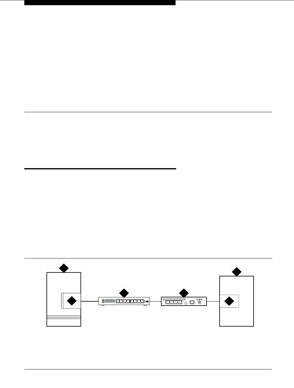
Issue 4 October 2002 121555-233-116
8
Terminal server installation
Overview
This chapter provides information on connecting adjunct equipment to the C-LAN
circuit pack, or to a G700 Media Gateway with an S8300 Media Server, using a
terminal server (Figure 21). Avaya supports the IOLAN+ 104 terminal server.
Any device that does not support a direct TCP/IP connection, but that does
support an RS232 interface, can connect through a terminal server. Property
management systems (PMS), system printers, and some CDR devices use
RS232 connections and can connect through a terminal server.
You can connect up to four adjuncts through one terminal server.
Figure 21. Switch-to-adjunct LAN connectivity through a terminal server
1. switch
2. C-LAN circuit pack, or IP connection on
an S8300/G700 configuration
3. 10/100Base-T Hub (optional)
4. terminal server
5. serial port
6. CDR
LAN
cydfadj KLC 091302
1
25
6
3
DATA CONNECTIONS ONLY - NOT FORTELECOM USE
1234 10BASE-T 5VDC
4

Terminal server installation
555-233-116
122 Issue 4 October 2002
Installing and administering the
terminal server
Make sure you have all the equipment on site before the installation. You must
have the hardware listed in Table 14.
You also need a computer (laptop) with the HyperTerminal software program for
the initial administration of the IOLAN+ and to set up the ports.
The general process is to
■Connect the IOLAN+ to the adjunct and the LAN
■Administer the ports on the IOLAN+ using a PC or laptop at the local site
■Test the connectivity back through the switch
Distance limits
The distance limit from the switch to the LAN hub is 328 feet (100 meters). The
distance limit from the LAN hub to the terminal server is 328 feet (100 meters). If
installed, the limit from the terminal server to the adjunct is 50 feet (15 meters).
Table 14. Required equipment
Comcode Description Qty Supplier
700015084 IOLAN+ 104 communications server 1 Avaya
NA RJ45-to-DB25 connector for IOLAN+
(supplied with 700015084) 4 Avaya
NA DB25-to-DB9 connector for PC COM port 1 Avaya
NA RS232 Null modem (if needed for PC or
printer connectivity) 1 or more Avaya
405369042 Male/female adapter (if necessary) 1 or more Avaya
846943306
or 104154414
NA
6-inch RJ45 crossover cord, or
10/100Base-T auto-sensing LAN hub or
router
1
1
Avaya
Customer
102631413
NA
259A adapter, or
CAT5 cross connect hardware and
connecting blocks
1 Avaya
Customer
NA RJ45 UTP Category 5 modular cords 1–2Customer
NA 451A in-line RJ45 adapters, as needed to
connect modular cords together
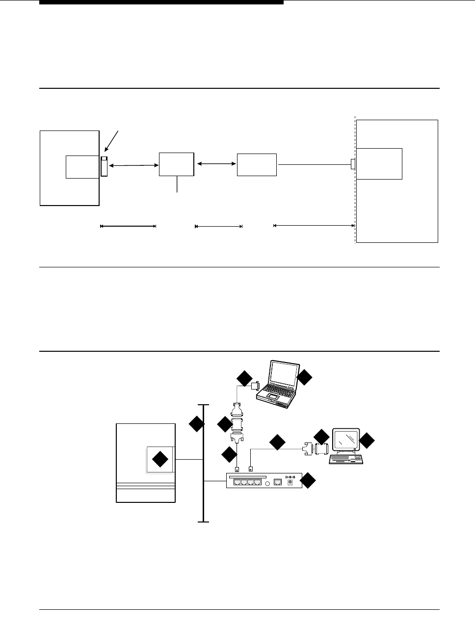
Installing and administering the terminal server
Issue 4 October 2002 123555-233-116
Cabling diagram
Figure 22 shows the connection between the terminal server port and a call
accounting system.
Figure 22. Stand-alone call accounting system link using a terminal server
Making the connections
Connect the adjunct to the IOLAN+, using the RJ45-to-DB25 cable and the null
modem. You can use a male/female adapter. See Figure 23.
Figure 23. Connecting an adjunct to the IOLAN+
1. C-LAN circuit pack, or IP connection on
an S8300/G700
2. Local area network (LAN)
3. IOLAN+ 104 terminal server
4. Adjunct (system management terminal
or a system printer, for example)
5. Null modem
6. PC or laptop (for initial administration)
7. DB25-to-RJ45 cable
8. DB25-to-DB9 cable
clan2gca.cdr 50 Ft. Maximum
Standalone
Call Accounting
Call
Accounting
Port
Demarcation
Point
M25A or M25B
RS232 Cable
«
C-LAN
Switch
Hub or
Router
328 ft max
(100 m) 328 ft max
(100 m)
AC Power
Terminal Server
RJ45 Cat 5
Modular Cord RJ45 Cat 5
Modular Cord
259A Adapter,
356A Adapter (Jack #1), or
258B Adapter (Jack #1)
cydfrcon KLC 021201
1
2
4
DATA CONNECTIONS ONLY - NOT FORTELECOM USE
1234 10BASE-T 5VDC 3
7
7
8
5
5
6

Terminal server installation
555-233-116
124 Issue 4 October 2002
Follow these typical steps:
NOTE:
Depending on the adjunct’s connections, you may not need all of these
pieces.
1. Connect the null modem adapter to COM1 port on the adjunct.
NOTE:
The null modem is an important element in this setup. Without it, data may
not transfer correctly.
2. Connect the other end of the null modem adapter to the DB25 to RJ45
cable.
3. Connect the RJ45 end to any port on the IOLAN+.
Administering the IOLAN+
To administer the IOLAN+ the first time, you must connect a PC or laptop to the
RS232 Port 1 on the IOLAN+ terminal server. Follow these typical steps:
NOTE:
Depending on the computer’s COM port, you may not need all of these
pieces.
1. Connect the DB9 end of the DB9-to-DB25 cable to the COM port on the PC
or laptop.
2. Connect the DB25 end to the null modem adapter.
3. Connect the other end of the null modem adapter to the DB25 to RJ45
cable.
4. Connect the RJ45 end to Port 1 of the IOLAN+.
Before beginning the initial administration, make sure you have the following
information:
■New IP address and subnet mask for IOLAN+
■Host name for IOLAN+
■IP address of C-LAN Ethernet interface
■Port number of C-LAN Ethernet interface where adjunct connects.

Installing and administering the terminal server
Issue 4 October 2002 125555-233-116
Setting up HyperTerminal on the computer
Use the HyperTerminal software program that comes with Windows 95/98/NT/
2000 to administer the IOLAN+.
1. Open HyperTerminal.
2. Click on File > Properties > Connect tab. In the Connect using: field,
select COM n, where n is the communication port your computer is using.
3. Click on CONFIGURE and set the bits per second field to 9600 and the Flow
control field to Hardware.
4. Click OK.
5. Press ENTER to get the login prompt.
Navigating the IOLAN+ terminal server
Refer to the IOLAN+ user guide for details. In general,
■Use the arrow keys to move to a menu item
■Use the TAB key to move from field to field horizontally.
■Use the ENTER key to choose an item.
Administering the IOLAN+ the first time
1. At the login prompt type any text and press ENTER.
2. At the second prompt type set term ansi and press ENTER to view the
Connections menu.
Name: port 2 CONNECTIONS MENU Terminal: 2
Connection Host
1 *** FREE ** === Commands ===
2 *** FREE ** | Telnet ^T|
3 *** FREE ** | Rlogin ^R|
4 *** FREE ** | Port ^P|
| Admin mode ^A|
| CLI |
| Lock |
| Logout ^D|
================
________________________________________________________________________________
IOLAN PLUS v4.02.00 a CDi iolan

Terminal server installation
555-233-116
126 Issue 4 October 2002
3. Under Connection select Port 1 (the port to which the adjunct is connected)
and press ENTER to access the Commands menu.
4. Select Admin mode > Password and press ENTER.
.
5. Type iolan, the default password, and press ENTER.
The Administration Menu changes, offering more options.
6. Select server and press ENTER to view the Server Configuration menu.
Name: port 2 ADMINISTRATION MENU Terminal: 2
gateway Examine/modify gateway table.
host Examine/modify host table.
line Terminal configuration organised by line.
password Specify password to allow modification of menu items.
port Terminal configuration organised by port.
quit Return to connections menu.
server Examine/modify Server parameters.
stats Examine Server statistics.
Password [ ]
________________________________________________________________________________
IOLAN PLUS v4.02.00 a CDi iolan-st
** Administrator ** SERVER CONFIGURATION Terminal: 2
Name [iolan ] Debug mode [0 ]
IP address [123.45.67.89 ]
Subnet mask [222.222.0.0 ]
Ethernet address [00:80:d4:03:11:cd] Ethernet interface [AUTO ]
Language [English ]
Identification [ ]
Lock [Disabled]
Password limit [5 ]
CR to initiate [No ]
SNAP encoding [Disabled]
Boot host [ ] Boot diagnostics [Enabled ]
Boot file [ ]
Init file [ ]
MOTD file [ ]
Domain name [ ]
Name server [ ] NS Port [53 ]
WINS server [ ]
________________________________________________________________________________
Name used for prompts and message on bottom right of screen.
IOLAN PLUS v4.02.00 a CDi iolan

Installing and administering the terminal server
Issue 4 October 2002 127555-233-116
7. Fill in the following fields with information appropriate to your network.
Leave the default settings for the other fields.
■Name:
■IP address: (for IOLAN+)
■Subnet mask:
8. Press ENTER and select Save & Exit to effect the changes.
Rebooting the IOLAN+
You must reboot the server any time you change an IP address or Local Port
value.
1. Press ENTER to view the Administration Menu.
.
NOTE:
The following steps re-initialize the IOLAN+ so it knows it’s connected to the
LAN through its IP address.
2. Select reboot and press ENTER.
3. Press the space bar to restart the IOLAN+.
** Administrator ** ADMINISTRATION MENU Terminal: 2
access Remote System Access (PPP).
change Change login and/or admin password.
gateway Examine/modify gateway table.
host Examine/modify host table.
kill Kill TCP connections on serial line.
line Terminal configuration organised by line.
port Terminal configuration organised by port.
quit Return to connections menu.
reboot Reboot Server.
server Examine/modify Server parameters.
stats Examine Server statistics.
trap Examine/modify SNMP Trap parameters.
Port [2 ]
________________________________________________________________________________
IOLAN PLUS v4.02.00 a CDi iolan

Terminal server installation
555-233-116
128 Issue 4 October 2002
Administering the gateway
NOTE:
If the C-LAN circuit pack and IOLAN+ are in the same subnet, skip this step.
1. Select Admin mode > Password and press ENTER.
2. Type iolan and press ENTER.
3. Select gateway to access the Gateway menu
4. Fill in the following fields for Entry 1:
■Destination: C-LAN IP address
■Gateway: Gateway address
■Netmask: Subnet mask
NOTE:
The following steps re-initialize the IOLAN+ so it knows it’s connected
to the LAN through your gateway.
5. Select reboot and press ENTER.
6. Press the space bar to restart the IOLAN+.
Administering an IOLAN+ port
Use this procedure when connecting an adjunct or serial COM port on a PC
directly (locally) to the IOLAN+ (see Figure 23).
1. Select Admin mode > Password and press ENTER.
2. Type iolan and press ENTER.
3. Select port and press ENTER.
4. Type port number, where port number is the port that the adjunct
connects to, and press ENTER to view the Port Setup Menu.

Installing and administering the terminal server
Issue 4 October 2002 129555-233-116
5. Fill in the following fields. Leave the default settings for the other fields.
■Speed: 19200
■Monitor DSR: Yes
■Monitor DCD: No
■Name: port number or other descriptive name
■Terminal type: undef
■CLI/Menu: CLI
■Reset Term: No
■Flow ctrl: Both
NOTE:
This is very important! If the link goes down between the
terminal server and the adjunct, the terminal server buffers the
data and notifies the switch. Once the terminal server buffer
fills up, the switch buffers the data. The switch raises an alarm
once the switch buffer is full.
■IP addresses: leave blank
■Mask: leave blank
■Access: Local
■Authentication: None
■Mode: Telnet
■Connection: Initiated
** Administrator ** PORT SETUP MENU Terminal: 2
Hardware Flow ctrl Keys
Speed [19200 ] Flow ctrl [Hardware] Hot [^]] Intr [^C]
Parity [None] Input Flow [Enabled ] Quit [^@] Kill [^U]
Bit [8] Output Flow [Enabled ] Del [^@] Sess [^@]
Stop [1 ] Echo [^@]
Break [Disabled] IP Addresses
Monitor DSR [Yes ] Src [ ] Mask [ ]
Monitor DCD [No ] Dst [ ]
User Options Access
Name [port 2 ] Keepalive [No ] Access [Local ]
Terminal type [undef ] Rlogin/Telnet [Telnet] Authentication [None ]
TERM [ ] Debug options [No ] Mode [Telnet ]
Video pages [0] Map CR to CR LF [No ] Connection [initiated]
CLI/Menu [CLI] Hex data [No ] Host [ ]
Reset Term [No ] Secure [No ] Remote Port [9001 ]
MOTD [No ] Local Port [10002]
________________________________________________________________________________

Terminal server installation
555-233-116
130 Issue 4 October 2002
■Host: C-LAN IP Address
■Remote Port: C-LAN Ethernet port where IP adjunct service is
offered
■Local Port: must match the value of Remote Port on the DEFINTY
IP Services screen
6. Press ENTER and select Save & Exit to effect the changes.
7. Press ENTER again to view the Administration Menu.
8. Select kill to disable the port connection.
9. Repeat the steps for each additional port you want to administer.
10. When administration is complete, from the Connections Menu, select
logout (or press Ctrl D).
11. Close HyperTerminal.
At this point, you have established a connection path from the adjunct
through the IOLAN+ to the C-LAN circuit pack.
Testing
1. On the system management terminal, press ENTER to get the login prompt
to the DEFINITY switch.
NOTE:
If you get garbled text, check the baud rate setting on the Port Setup
Menu. You can adjust it up or down.
2. If no login prompt appears, log back into the IOLAN+ through
HyperTerminal.
3. Select Admin mode > stats and press ENTER twice.
4. Select users and press ENTER.
5. Look at the port that the adjunct is connected to and see if there is any
traffic. If not, check all your connections and administration fields.

Administering IP node names
Issue 4 October 2002 131555-233-116
After you have successfully administered and validated the connection between
the adjunct and the C-LAN circuit pack through the IOLAN+, you can disconnect
the laptop or other PC from the IOLAN+. No further IOLAN+ administration is
required.
Potential failure scenarios and repair actions
If a link goes down between the terminal server and the switch, you must reboot
the terminal server for the link come back up. If you are performing a software
upgrade or if a system reset occurs, you must reboot the terminal server to restore
the link. See ‘‘Rebooting the IOLAN+’’ on page 127 for instructions.
Administering IP node names
You must administer the IP addresses of the C-LAN board, any adjunct that
connects directly to the LAN, the terminal server (if appropriate), and the PC
running the Reliable Session-Layer Protocol (if appropriate). You use the Node
Names screen to do this.
1. Type change node-names ip and press RETURN.
2. Enter the name and the IP address of the C-LAN board, as well as any
adjunct, terminal server or PC you need to administer.
** Administrator ** SERVER STATISTICS Terminal: 2
1. port1 Talking to host 172.22.22.67.5111<DSR+CTS+DCD >DTR+RTS
2. port 2 SERVER STATISTICS <DSR+DCD >DTR+RTS
3. port 3 waiting for DSR or DCD >DTR+RTS
4. port 4 modem waiting for DSR or DCD >DTR+RTS
REM <unknown> logged out
LOG logger not enabled
________________________________________________________________________________
Press <RETURN> to see list of options.
IOLAN PLUS v4.02.00 a CDi iolan-st

Terminal server installation
555-233-116
132 Issue 4 October 2002
3. Print a copy of this screen, or write down the node names you entered. You
need this information for the next administration task.
4. Press ENTER to save your changes.
Administering IP services
For each adjunct that you connect using TCP/IP, you need to administer IP
services to establish the IP address/TCP port pairing. The IP address is
associated with the node name that you just administered. In this example, we are
administering the primary CDR connection as end-to-end TCP/IP, and the PMS
connection through a terminal server.
1. Type change ip-services and press RETURN to assign the CDR endpoint.
2. In the Service Type field, enter CDR1 for the call accounting link, and
PMS for the property management system.
3. In the Local Node field, enter the node name for the switch. In this
example, switch is the local node.
change node-names ip Page 1 of 1
NODE NAMES
Name IP Address Name IP Address
1. switch________ 123.456.7 .89 17. ______________ ___.___.___.___
2. callacctg_____ 123.456.9 .00 18. ______________ ___.___.___.___
3. termserver____ 123.456.11 .00 19. ______________ ___.___.___.___
4. pmslogpc______ 123.456.78 .00 20. ______________ ___.___.___.___
5. ______________ ___.___.___.___ 21. ______________ ___.___.___.___
6. ______________ ___.___.___.___ 22. ______________ ___.___.___.___
7. ______________ ___.___.___.___ 23. ______________ ___.___.___.___
8. ______________ ___.___.___.___ 24. ______________ ___.___.___.___
9. ______________ ___.___.___.___ 25. ______________ ___.___.___.___
10. ______________ ___.___.___.___ 26. ______________ ___.___.___.___
11. ______________ ___.___.___.___ 27. ______________ ___.___.___.___
12. ______________ ___.___.___.___ 28. ______________ ___.___.___.___
13. ______________ ___.___.___.___ 29. ______________ ___.___.___.___
14. ______________ ___.___.___.___ 30. ______________ ___.___.___.___
15. ______________ ___.___.___.___ 31. ______________ ___.___.___.___
16. ______________ ___.___.___.___ 32. ______________ ___.___.___.___
change ip-services Page 1 of 3
IP SERVICES
Service Enabled Local Local Remote Remote
Type Node Port Node Port
CDR1 switch 0 callacctg 5101
PMS switch 0 termserver 5103
Administering IP services
Issue 4 October 2002 133555-233-116
4. The Local Port field defaults to 0 for all client applications. You cannot
make an entry in this field.
5. In the Remote Node field, enter the node name for the adjunct, as
administered on the Node Names screen. For the call accounting
application, type callacctg. Since the PMS application routes through the
terminal server, termserver is the remote node for this service type.
6. In the Remote Port field, enter the TCP listen port assigned to the
adjunct. The recommended value for CDR1 is 5101, and the
recommended value for PMS is 5103.
NOTE:
This number must match the port administered on the end device. If
you are using the Downloadable Reliable Session-Layer Protocol
tool, this must match the port administered in the Server application.
If you are using a terminal server, this number must match the Local
Port number on the Port Setup menu. Consult the documentation
for your Call Accounting system to determine the appropriate port for
the CDR device.
7. Move to Page 3. Type y in the Reliable Protocol field for the CDR
Service Type.
8. Press ENTER to save your changes.
change ip-services Page 3 of 3
SESSION LAYER TIMERS
Service Reliable Packet Resp Session Connect SPDU Connectivity
Type Protocol Timer Message Cntr Cntr Timer
CDR1 y 3 1 1 1

Terminal server installation
555-233-116
134 Issue 4 October 2002

Issue 4 October 2002 135555-233-116
9
DS1/T1 CPE loopback jack
This chapter provides information on how to install and use a DS1 loopback jack
to test the DS1 span between the Avaya Media Server or Gateway and the
network interface point. The loopback jack is required when DC power is at the
interface to the integrated channel service unit (ICSU).
NOTE:
Do not remove the loopback jack after installation. It should always be
available for remote tests of the DS1 span.
NOTE:
For G700 Media Gateway systems, the channel service unit (CSU) is
integrated within the MM710 board. This means that there is no need for a
separate external device. For earlier media gateway systems, the integrated
channel service unit (ICSU) — also known as the 120A2 — is a separate
device that plugs into the back of the media gateway.
For G700 Media Gateway systems, the loopback jack isolates the MM710
internal CSU from the DC power and properly loops the DC span power.
Installing a loopback jack
You can install a loopback jack with or without a smart jack.
With a smart jack
Install the loopback jack at the interface to the smart jack, if possible. This position
provides maximum coverage of CPE wiring when remote loopback tests are run.

DS1/T1 CPE loopback jack
555-233-116
136 Issue 4 October 2002
If the smart jack is not accessible, install the loopback jack at the extended
demarcation point.
If there is no extended demarcation point, install the loopback jack directly at the
network interface point as shown in Figure 24 and Figure 25.
If there is an extended demarcation point and the smart jack is not accessible,
install the loopback jack as shown in Figure 26 and Figure 27.
If there is an extended demarcation point, but the smart jack is accessible, install
the loopback jack as shown in Figure 28 and Figure 29.
1. To install the loopback jack, simply disconnect the RJ-48 (8-wide)
connector at the appropriate interface point and connect the loopback jack
in series with the DS1 span. See Figure 24 through Figure 33.
2. Plug the H600-383 cable from the ICSU, or from the MM710, into the
female connector on the loopback jack.
3. Plug the male connector on the loopback jack cable into the network
interface point.
NOTE:
Do not remove the loopback jack after installation. This is not a test
tool and should always be available to remotely test a DS1 span.
Without a smart jack
Install the loopback jack at the point where the cabling from the ICSU plugs into
the dumb block. If there is more than one dumb block, choose the one that is
closest to the Interface Termination feed or the fiber MUX to provide maximum
coverage for loopback jack tests. Refer to Figure 30 through Figure 33.
1. To install the loopback jack, simply disconnect the RJ-48 (8-wide)
connector at the appropriate interface point and connect the loopback jack
in series with the DS1 span. See Figure 24 through Figure 33.
2. Plug the H600-383 cable from the ICSU, or from the MM710, into the
female connector on the loopback jack.
3. Plug the male connector on the loopback jack cable into the network
interface point.
NOTE:
Do not remove the loopback jack after installation. This is not a test
tool and should always be available to remotely test a DS1 span.

Administering the loopback jack
Issue 4 October 2002 137555-233-116
Administering the loopback jack
1. At the management terminal, enter change ds1 location, where location
is the DS1 interface circuit pack corresponding to the loopback jack.
2. Be sure the near-end CSU type is set to integrated.
3. On page 2 of the form, change the supply CPE loopback jack power
field to y.
Setting this field to y informs the technician that a loopback jack is present
on the facility and allows the technician to determine that the facility is
available for remote testing.
4. Enter save translation to save the new information.
Loopback testing with a smart jack
The loopback jack and smart jack isolate faults by dividing the DS1 span into 3
sections (see Figure 24, through Figure 29):
■From the 120A2 (or later) ICSU, or from the MM710, to the loopback jack
■From the loopback jack to the smart jack (network interface point)
■From the smart jack to the CO
The first 2 sections are your responsibility. The last is the responsibility of the DS1
service provider.
Testing the DS1 span from the ICSU to the
loopback jack
The DS1 span test has 2 parts.
■Checking for circuit connectivity
The first part of the test powers-up the loopback jack and sends a signal
from the DS1 circuit pack, through the wiring, to the loopback jack. The test
allows about 10 seconds for the signal to loop around the loopback jack
and return to the DS1 circuit pack. Then it sends the results to the
management terminal and proceeds to the second part of the test.
■The second part of the test sends the standard, 3-in-24 DS1 stress-testing
pattern from the DS1 board, through the loopback jack, and back to a bit
error detector and counter on the DS1 board. A bit-error rate counter
displays the results on the management terminal until you terminates the
test.
Always perform both parts of the test. Proceed as follows.

DS1/T1 CPE loopback jack
555-233-116
138 Issue 4 October 2002
Checking the integrity of local equipment
Before you go any further, make sure that the problem is actually on the DS1 span
by testing the equipment that connects to the span at the near end. Test the DS1
circuit pack, and perform any needed maintenance or repairs.
Busying out the DS1 circuit pack
Now take the DS1 circuit out of service.
NOTE:
If you have a G700 Media Gateway, substitute XXXVS for UUCSS in the
following command, where XXX is the administered number of the G700 (for
example, 002), and VS is the slot number on the G700 of the Media Module
(for example, V3). The V is not a variable and needs to be included in the
command exactly where shown. A sample address for a DS1 circuit pack on
a G700 Media Gateway might look like this: 002V3.
1. Once you are sure that the DS1 circuit pack and ICSU are functioning
correctly, go to the management terminal and busy out the DS1 circuit pack
by typing busyout board UUCSS, where UU is the cabinet number, C is
the carrier letter, and SS is the slot number of the DS1 board.
Administering the DS1 for the test
1. At the management terminal, open the DS1 administration form. Type
change ds1 UUCSS, where UU is the cabinet number, C is the carrier
letter, and SS is the slot number of the DS1 board.
2. Make sure that the near-end csu type field is set to integrated.
3. Change to page 2 of the DS1 administration form, and confirm that the
value of the TX LBO field is 0dB.
4. If the value of the TX LBO field is not 0dB, record the current value. Then
set the TX LBO field to 0dB for testing.
5. Press ENTER to make the changes, CANCEL to quit without changes.
Testing the integrity of the loopback circuit
Now perform the first part of the actual loopback test.
NOTE:
If you have a G700 Media Gateway, substitute XXXVS for UUCSS in the
following command, where XXX is the administered number of the G700 (for
example, 002), and VS is the slot number on the G700 of the Media Module
(for example, V3). The V is not a variable and needs to be included in the
command exactly where shown. A sample address for a DS1 circuit pack on
a G700 Media Gateway might look like this: 002V3.

Loopback testing with a smart jack
Issue 4 October 2002 139555-233-116
1. At the management terminal, enter test ds1-loop UUCSS cpe-loopback-
jack, where UU is the cabinet number, C is the carrier letter, and SS is the
slot number of the DS1 board.
The loopback jack powers up. Active, DS1 facility alarms (if any) clear.
After about 20 seconds, the first set of results appears on the terminal.
2. If FAIL appears on the terminal display, there may be a fault in the wiring
between the ICSU and the loopback jack or the loopback jack may itself be
faulty. Isolate the problem by replacing the loopback jack and repeating
Step 1.
3. If FAIL still appears after the loopback jack has been replaced, suspect a
wiring problem. Replace the cable between the ICSU and the loopback
jack. Then repeat Step 1.
4. When PASS appears on the terminal, proceed with the second part of the
test, checking the integrity of transmitted data.
Testing the integrity of data sent over the loop
Now perform the second part of the test, checking for data errors.
NOTE:
The loss of signal (LOS) alarm (demand test #138) is not processed
during this test while the 3-in-24 pattern is active.
Clearing the results of previous tests
NOTE:
If you have a G700 Media Gateway, substitute XXXVS for UUCSS in the
following commands, where XXX is the administered number of the G700
(for example, 002), and VS is the slot number on the G700 of the Media
Module (for example, V3). The V is not a variable and needs to be included
in the commands exactly where shown. A sample address for a DS1 circuit
pack on a G700 Media Gateway might look like this: 002V3.
1. Zero out the bit-error counter. At the management terminal, enter clear
meas ds1 loop UUCSS, where UU is the cabinet number, C is the carrier
letter, and SS is the slot number of the DS1 board.
2. Zero out the performance measurement counter. At the management
terminal, enter clear meas ds1 log UUCSS, where UU is the cabinet
number, C is the carrier letter, and SS is the slot number of the DS1 board.
3. Zero out the ESF error count. At the management terminal, enter clear
meas ds1 esf UUCSS, where UU is the cabinet number, C is the carrier
letter, and SS is the slot number of the DS1 board.

DS1/T1 CPE loopback jack
555-233-116
140 Issue 4 October 2002
Running the data test
NOTE:
If you have a G700 Media Gateway, substitute XXXVS for UUCSS in the
following command, where XXX is the administered number of the G700 (for
example, 002), and VS is the slot number on the G700 of the Media Module
(for example, V3). The V is not a variable and needs to be included in the
command exactly where shown. A sample address for a DS1 circuit pack on
a G700 Media Gateway might look like this: 002V3.
1. Display the bit error count. At the management terminal, enter list meas
ds1 sum UUCSS, where UU is the cabinet number, C is the carrier letter,
and SS is the slot number of the DS1 board.
2. Step through Table 15 to troubleshoot.
Table 15. DS1 Troubleshooting
Condition Solution
The value of the Test: cpe-loopback-
jack field is Pattern 3-in-24 The loopback jack test is active.
The value of the Synchronized field is NRetry the test 5 times.
The value of the Synchronized field
remains N after 5 tries. Excessive bit errors are likely. Check for
intermittent connections or broken wires in an
SPE receive or transmit pair, and repair as
necessary. Then repeat step 1.
The value of the Bit-error count field is
non-zero Repeat step 1 several times.
The value of the Synchronized is YThe DS1 circuit pack has synchronized to the
looped 3-in-24 pattern and is counting bit
errors in the pattern.
The value of the Bit-error count field
pegs at 75535 or increments by 100s or
1000s each time you repeat step 1.
Suspect loose or corroded connections,
severe crosstalk, or impedance imbalances
between the two conductors of the receive or
transmit pair. Wiring may need replacement.
The value of the Bit-error count field
is 0There are no obvious wiring problems. Verify
this by repeating step 1 at 1-minute to
10-minute intervals until you are certain.
If the test reports no errors for 1 minute, the
error rate is less than 1 in 108. If the test
reports no errors for 10 minutes, the error
rate is less than 1 in 109.
Continued on next page

Loopback testing with a smart jack
Issue 4 October 2002 141555-233-116
NOTE:
If you have a G700 Media Gateway, substitute XXXVS for UUCSS in the
following commands, where XXX is the administered number of the G700
(for example, 002), and VS is the slot number on the G700 of the Media
Module (for example, V3). The V is not a variable and needs to be included
in the commands exactly where shown. A sample address for a DS1 circuit
pack on a G700 Media Gateway might look like this: 002V3.
3. Once you are fairly certain that the test is reporting no errors (after at least
1 error-free minute), confirm that the 3-in-24 pattern error detector is
operating. Enter test ds1-loop UUCSS inject-single-bit-error, where UU
is the cabinet number, C is the carrier letter, and SS is the slot number of
the DS1 board.
4. Display the bit error count again. At the management terminal, enter list
meas ds1 sum UUCSS, where UU is the cabinet number, C is the carrier
letter, and SS is the slot number of the DS1 board.
5. End the test. Enter test ds1-loop location end cpe-loopback-jack-test.
6. Wait about 30 seconds for the DS1 to reframe on the incoming signal and
clear DS1 facility alarms.
Condition Solution
The value of the Bit-error count field is
greater than 1Replace the ICSU, and retest.
The value of the Bit-error count field is still
greater than 1 after you replace the ICSU. Replace the DS1 circuit pack, and retest.
The value of the Bit-error count field is 1The test passed.
Condition Solution
Loopback termination fails with
an error code of 1313. The span is still looped somewhere, possibly at the
loopback jack, at the ICSU, or somewhere in the
network.
The red LED on the loopback
jack is on. Replace the ICSU, and re-run the test.
Loopback termination still fails. Replace the DS1 circuit pack, and repeat the test
The DS1 cannot frame on the
incoming span’s signal after
the loopback jack power down.
There is something wrong with the receive signal into
the loopback jack from the dumb block or the smart
jack.
The span failed the service
provider’s loopback test. The problem is in the service provider’s network.

DS1/T1 CPE loopback jack
555-233-116
142 Issue 4 October 2002
Restoring DS1 administration
NOTE:
If you have a G700 Media Gateway, substitute XXXVS for UUCSS in the
following command, where XXX is the administered number of the G700 (for
example, 002), and VS is the slot number on the G700 of the Media Module
(for example, V3). The V is not a variable and needs to be included in the
command exactly where shown. A sample address for a DS1 circuit pack on
a G700 Media Gateway might look like this: 002V3.
1. At the management terminal, open the DS1 administration form. Enter
change ds1 UUCSS, where UU is the cabinet number, C is the carrier
letter, and SS is the slot number of the DS1 board.
2. Change to page 2 of the DS1 administration form.
3. Change the value of the TX LBO field to the original value that you wrote
down when you were ‘‘Administering the DS1 for the test’’ on page 138.
4. Press ENTER to make the changes, CANCEL to quit without changes.
The service provider
successfully loop tested the
span, up to the smart jack.
The wiring between the loopback jack and the smart
jack is suspect. Test, and make repairs, as needed.
You cannot locate and repair
the problem in the time
available and must terminate
the test.
The test will not terminate normally in the absence of a
good framing signal. You have to reset the circuit pack.
Enter reset board UUCSS, where UU is the cabinet
number, C is the carrier letter, and SS is the slot
number of the DS1 board.
NOTE:
If you have a G700 Media Gateway, substitute
XXXVS for UUCSS in the above command,
where XXX is the administered number of the
G700 (for example, 002), and VS is the slot
number on the G700 of the Media Module (for
example, V3). The V is not a variable and needs
to be included in the command exactly where
shown. A sample address for a DS1 circuit pack
on a G700 Media Gateway might look like this:
002V3.
The test terminated normally. Proceed with ‘‘Restoring DS1 administration’’.
Condition Solution

Loopback testing with a smart jack
Issue 4 October 2002 143555-233-116
Releasing the DS1 circuit pack
NOTE:
If you have a G700 Media Gateway, substitute XXXVS for UUCSS in the
following command, where XXX is the administered number of the G700 (for
example, 002), and VS is the slot number on the G700 of the Media Module
(for example, V3). The V is not a variable and needs to be included in the
command exactly where shown. A sample address for a DS1 circuit pack on
a G700 Media Gateway might look like this: 002V3.
1. Release the DS1 circuit pack. From the management terminal, enter
release board UUCSS, where UU is the cabinet number, C is the carrier
letter, and SS is the slot number of the DS1 board.
2. Leave the loopback jack in place.
Testing the DS1 span from the smart jack to the
network interface termination or fiber
multiplexer (MUX)
1. Have the service provider run a smart-jack loopback test against the
network interface wiring that links the smart jack to the CO (section 3 in
Figure 24 through Figure 29).
2. If the tests fails, there is a problem on the network side. Have the service
provider correct it.
Testing the DS1 span from the loopback jack to
the smart jack
Test the short length of customer premises wiring between the loopback jack and
the smart jack (Section 2 in the following 3 figures) using a loopback that overlaps
this section of the span.
■Have the DS1 service provider at the CO end run a local ICSU line
loopback test.
■Have the DS1 service provider at the CO end run a local DS1 payload
loopback test.
■Run a far-end ICSU line loopback, using the procedure below.
NOTE:
This test cannot isolate the problem if there are problems in the wiring
between the far-end CO and the far-end ICSU. You must coordinate
this test with the DS1 service provider.

DS1/T1 CPE loopback jack
555-233-116
144 Issue 4 October 2002
NOTE:
If you have a G700 Media Gateway, substitute XXXVS for UUCSS in the
following command, where XXX is the administered number of the G700 (for
example, 002), and VS is the slot number on the G700 of the Media Module
(for example, V3). The V is not a variable and needs to be included in the
command exactly where shown. A sample address for a DS1 circuit pack on
a G700 Media Gateway might look like this: 002V3.
1. From the management terminal, enter test ds1-loop UUCSS far-
csu-loopback-test-begin, where UU is the cabinet number, C is
the carrier letter, and SS is the slot number of the DS1 board.
2. Examine the bit-error counts, as in ‘‘Testing the integrity of data sent
over the loop’’ on page 139."
3. Terminate the test. Enter test ds1-loop location end-loopback/
span-test.
3. If the tests fails and the there were no problems ‘‘Testing the DS1 span
from the ICSU to the loopback jack’’ or ‘‘Testing the DS1 span from the
smart jack to the network interface termination or fiber multiplexer (MUX)’’,
there is a problem between the loopback jack to the smart jack. Work with
the service provider to isolate the fault.
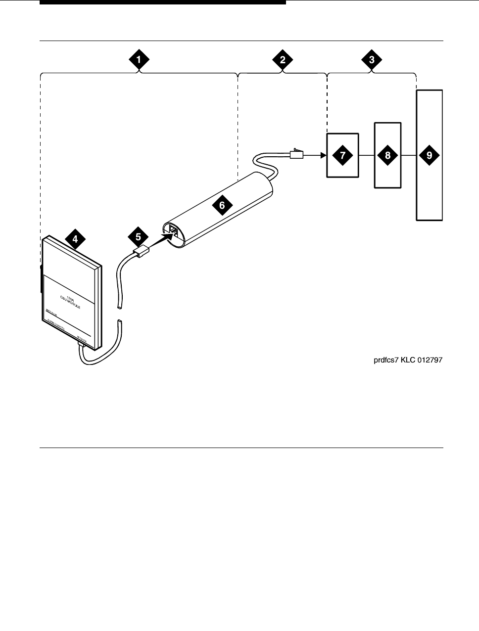
Loopback testing with a smart jack
Issue 4 October 2002 145555-233-116
Figure 24. Network interface at smart jack for a 120A2 (or later) ICSU
1. Span section 1
2. Span section 2
3. Span section 3
4. 120A2 (or later) ICSU
5. RJ-48 to network interface
(up to 1000 ft. [305 m])
6. Loopback jack
7. Network interface smart jack
8. Interface termination or fiber multiplexer (MUX)
9. Central office
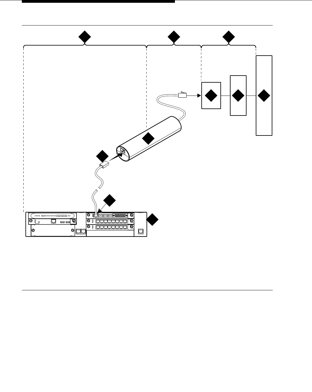
DS1/T1 CPE loopback jack
555-233-116
146 Issue 4 October 2002
Figure 25. Network interface at smart jack for an MM710 multi-media module
1. Span section 1
2. Span section 2
3. Span section 3
4. G700 Media Gateway
5. E1/T1 port on an MM710
multi-media module
6. RJ-48 to network interface (up to 1000 ft. [305 m])
7. Loopback jack
8. Network interface smart jack
9. Interface termination or fiber multiplexer (MUX)
10. Central office
prdfcs7a KLC 080602
ALM
TST
ACT
123456 87
ALM
TST
ACT
123456 87
REMOVE
ALM
TST
ACT
OK TO SHUT DOWN
SERVICES USB 1 USB 2
E1/T1 EIA 530A DCE
ALM
TST
ACT
SIG
EISO EMSM EOSI
1 2 3
4
5
6
7
8910
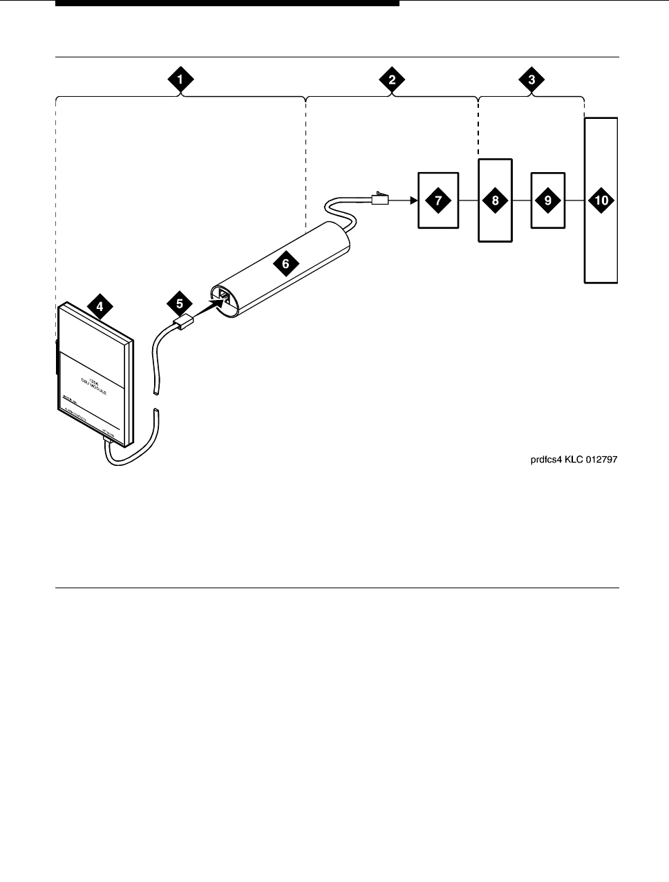
Loopback testing with a smart jack
Issue 4 October 2002 147555-233-116
Figure 26. Network interface at extended demarcation point (smart jack inaccessible) for
a 120A2 (or later) ICSU
1. Span section 1
2. Span section 2
3. Span section 3
4. 120A2 (or later) ICSU
5. RJ-48 to network interface
(up to 1000 ft. [305 m])
6. Loopback jack
7. Dumb block (extended demarcation)
8. Network interface smart jack
9. Interface termination or fiber multiplexer (MUX)
10. Central office
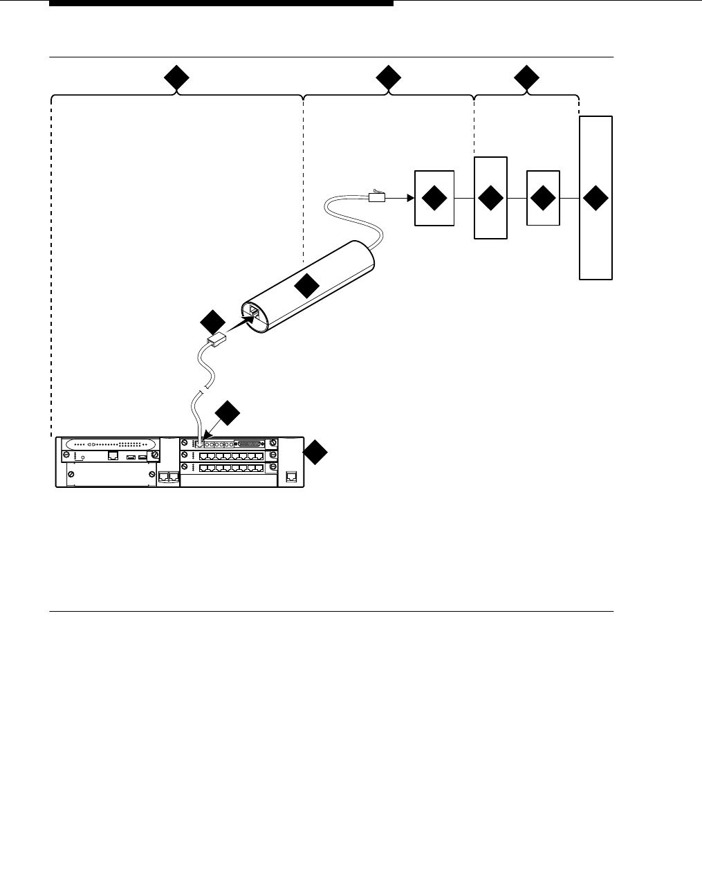
DS1/T1 CPE loopback jack
555-233-116
148 Issue 4 October 2002
Figure 27. Network interface at extended demarcation point (smart jack inaccessible) for
an MM710 multi-media module
1. Span section 1
2. Span section 2
3. Span section 3
4. G700 Media Gateway
5. E1/T1 port on an MM710
multi-media module
6. RJ-48 to network interface (up to 1000 ft. [305 m])
7. Loopback jack
8. Dumb block (extended demarcation)
9. Network interface smart jack
10. Interface termination or fiber multiplexer (MUX)
11. Central office
prdfcs4a KLC 080602
ALM
TST
ACT
123456 87
ALM
TST
ACT
123456 87
REMOVE
ALM
TST
ACT
OKTO SHUT DOWN
SERVICES USB 1 USB 2
E1/T1 EIA 530A DCE
ALM
TST
ACT
SIG
EISO EMSM EOSI
1 2 3
4
5
6
7
8910 11

Loopback testing with a smart jack
Issue 4 October 2002 149555-233-116
Figure 28. Network interface at extended demarcation point (smart jack accessible) for a
120A2 (or later) ICSU
1. Span section 1
2. Span section 2
3. Span section 3
4. 120A2 (or later) ICSU
5. RJ-48 to network interface
(up to 1000 ft. [305 m])
6. Dumb block (extended demarcation)
7. Loopback jack
8. Network interface smart jack
9. Interface termination or fiber multiplexer (MUX)
10. Central office
11. Dumb block to smart jack RJ-48
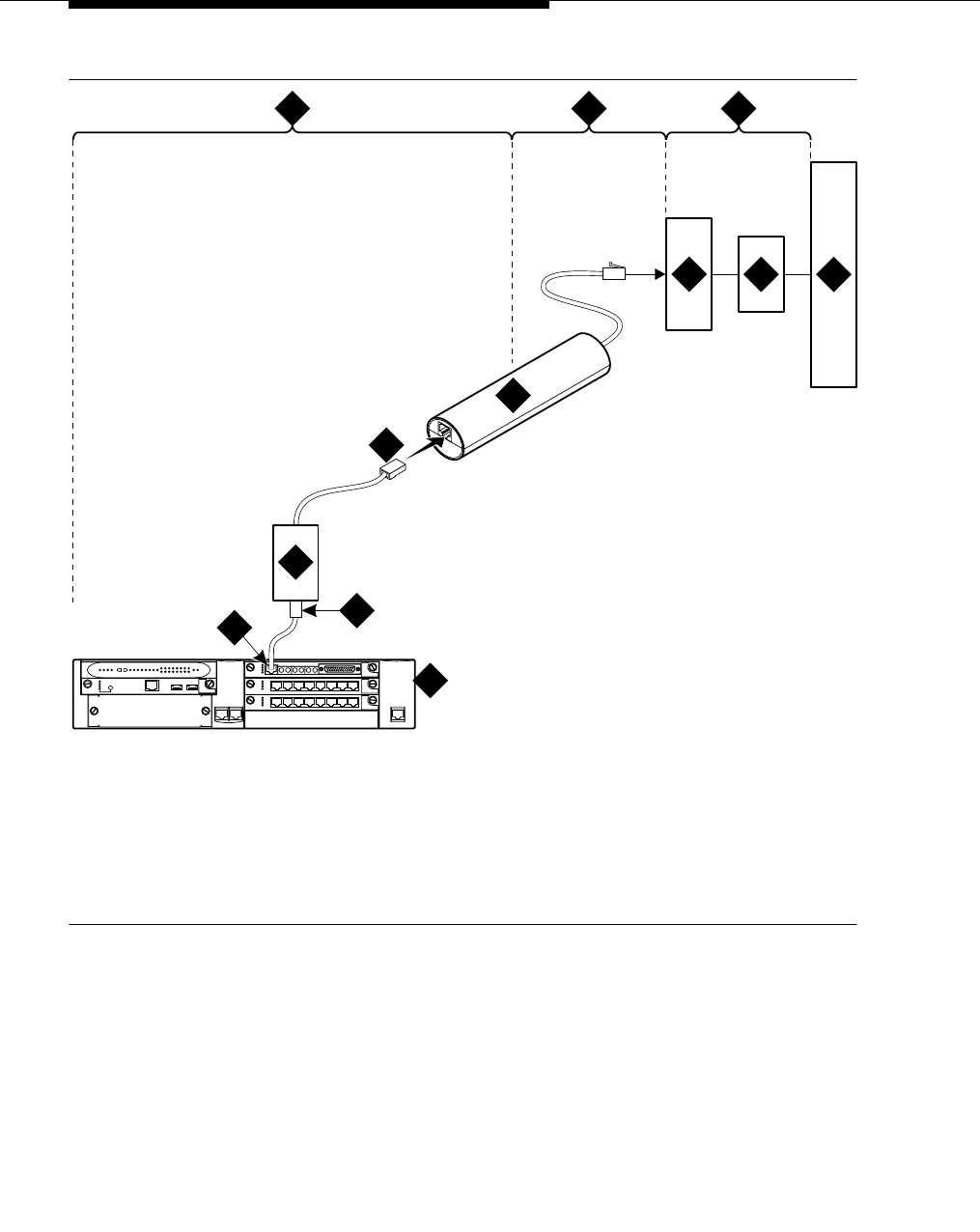
DS1/T1 CPE loopback jack
555-233-116
150 Issue 4 October 2002
Figure 29. Network interface at extended demarcation point (smart jack accessible) for
an MM710 multi-media module
1. Span section 1
2. Span section 2
3. Span section 3
4. G700 Media Gateway
5. E1/T1 port on an MM710
multi-media module
6. RJ-48 to network interface (up to 1000 ft. [305 m])
7. Dumb block (extended demarcation)
8. Loopback jack
9. Network interface smart jack
10. Interface termination or fiber multiplexer (MUX)
11. Central office
12. Dumb block to smart jack RJ-48
prdfcs5a KLC 080602
ALM
TST
ACT
123456 87
ALM
TST
ACT
123456 87
REMOVE
ALM
TST
ACT
OKTO SHUT DOWN
SERVICES USB1 USB 2
E1/T1 EIA 530A DCE
ALM
TST
ACT
SIG
EISO EMSM EOSI
1 2 3
4
56
8
910
12
11
7
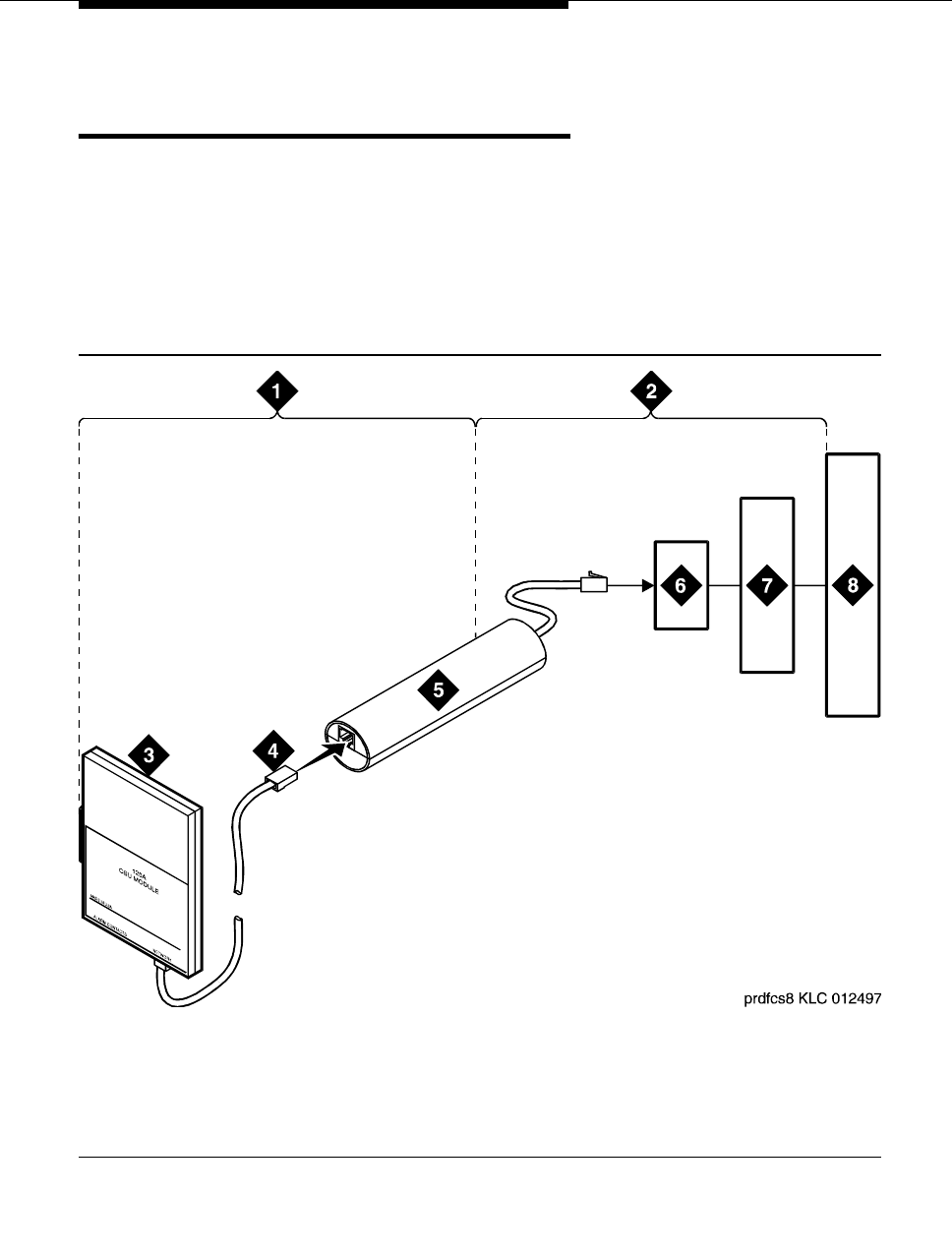
Testing a loopback jack without a smart jack
Issue 4 October 2002 151555-233-116
Testing a loopback jack without a
smart jack
When the loopback jack is added to a span that does not contain a smart jack, the
span is divided into 2 sections: from the ICSU, or from the MM710, to the
loopback jack and from the loopback jack to the central office (CO). Section 2
includes the short cable from the loopback jack to the dumb block demarcation
point (part of the loopback jack). This cable is the only part of Section 2 that is part
of customer premises wiring. It is not covered in the loopback jack’s loopback
path. See Figure 30 through Figure 33.
Figure 30. Network interface at “dumb” block for a 120A2 (or later) ICSU
1. Span section 1
2. Span section 2
3. 120A2 (or later) ICSU
4. RJ-48 to network interface
(up to 1000 ft. [305 m])
5. Loopback jack
6. Dumb block (demarcation point)
7. Interface termination or fiber multiplexer (MUX)
8. Central office
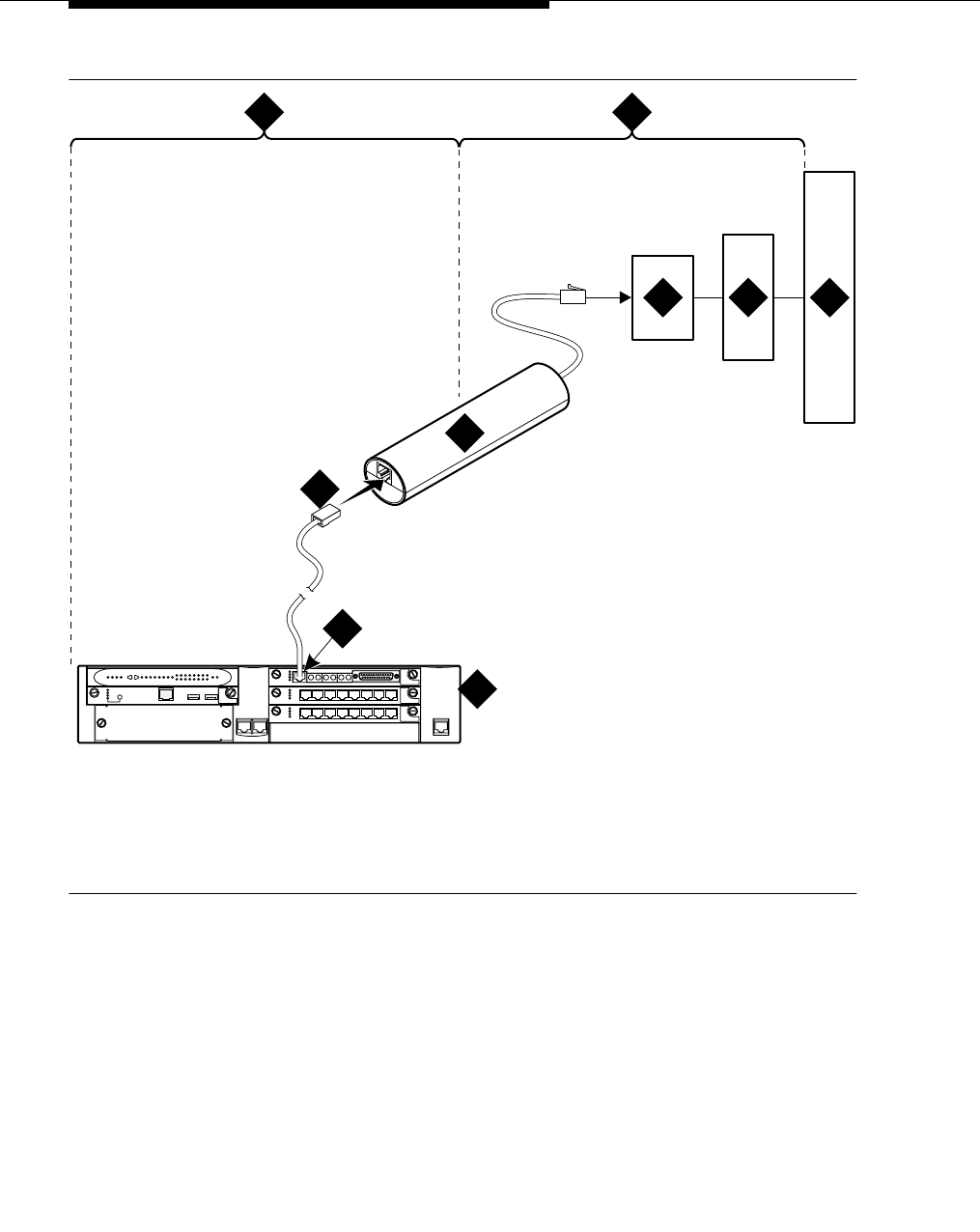
DS1/T1 CPE loopback jack
555-233-116
152 Issue 4 October 2002
Figure 31. Network interface at “dumb” block for an MM710 multi-media module
1. Span section 1
2. Span section 2
3. G700 Media Gateway
4. E1/T1 port on an MM710
multi-media module
5. RJ-48 to network interface (up to 1000 ft. [305 m])
6. Loopback jack
7. Dumb block (demarcation point)
8. Interface termination or fiber multiplexer (MUX)
9. Central office
prdfcs8a KLC 080602
ALM
TST
ACT
123456 87
ALM
TST
ACT
123456 87
REMOVE
ALM
TST
ACT
OK TO SHUT DOWN
SERVICES USB 1 USB2
E1/T1 EIA 530A DCE
ALM
TST
ACT
SIG
EISO EMSM EOSI
1 2
3
4
5
6
789
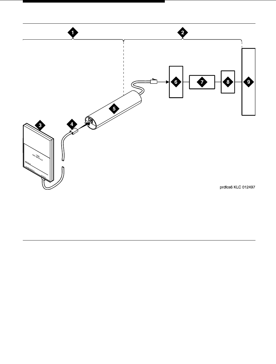
Testing a loopback jack without a smart jack
Issue 4 October 2002 153555-233-116
Figure 32. Network interface at “dumb” block with repeater line to fiber MUX for a
120A2 (or later) ICSU
1. Span section 1
2. Span section 2
3. 120A2 (or later) ICSU
4. RJ-48 to network interface
(up to 1000 ft. [305 m])
5. Loopback jack
6. Dumb block (demarcation point)
7. Repeater
8. Fiber multiplexer (MUX)
9. Central office
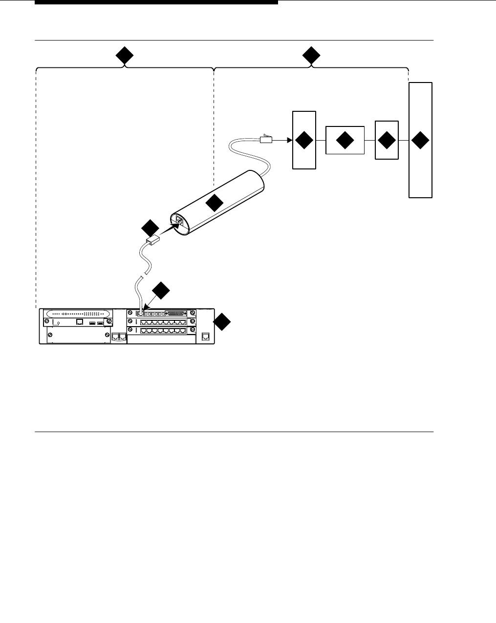
DS1/T1 CPE loopback jack
555-233-116
154 Issue 4 October 2002
Figure 33. Network interface at “dumb” block with repeater line to fiber MUX for an
MM710 multi-media module
You are responsible for finding and correcting problems in the customer wiring
(section 1 and the loopback cable portion of section 2). The DS1 service provider
is responsible for finding and correcting problems in the majority of section 2.
1. Span section 1
2. Span section 2
3. G700 Media Gateway
4. E1/T1 port on an MM710
multi-media module
5. RJ-48 to network interface (up to 1000 ft. [305 m])
6. Loopback jack
7. Dumb block (demarcation point)
8. Repeater
9. Fiber multiplexer (MUX)
10. Central office
prdfcs6a KLC 080602
ALM
TST
ACT
123456 87
ALM
TST
ACT
123456 87
REMOVE
ALM
TST
ACT
OKTO SHUT DOWN
SERVICES USB 1 USB2
E1/T1 EIA 530A DCE
ALM
TST
ACT
SIG
EISO EMSM EOSI
1 2
3
4
5
6
78 9 10

Testing a loopback jack without a smart jack
Issue 4 October 2002 155555-233-116
Proceed as follows.
1. Test customer premises wiring from the ICSU, or from the MM710, to the
loopback jack, as described in the “DS1 Span Test” section.
2. Test the loopback jack-to-dumb block and dumb block-to-CO wiring
(section 2 in Figure 30 through Figure 33). This can be done using a
loopback that “overlaps” the section of the span. Any of the following
loopbacks can do this:
■The local ICSU’s line loopback, which the DS1 service provider at
the CO end typically activates, tests, and then deactivates.
■The local DS1 interface’s payload loopback, which the DS1 service
provider at the CO end activates and tests.
■The far-end ICSU’s line loopback. Activate this test at the
management terminal by entering test ds1-loop location far-csu-
loopback-test-begin, where location is the DS1 interface circuit
pack corresponding to the loopback jack. Terminate this test by
entering test ds1-loop location end-loopback/span-test, where
location is the DS1 interface circuit pack corresponding to the
loopback jack.
Bit error counts are examined as described in the “DS1 Span Test”
section. This test only isolates problems to Section 2 wiring if there
are no problems in the wiring between the far-end CO and the far-
end ICSU. Coordinate this test with the DS1 service provider.
Failure of any of the above tests (a, b, or c) indicate a problem in
Section 2. This could mean bad loopback jack -to-”dumb” block
cabling, but is more likely to indicate a problem somewhere between
the “dumb” block and the CO. This is the responsibility of the DS1
service provider.
If the DS1 Span Test confirms that there are no problems in
Section 1, the technician should proceed as follows to avoid
unnecessary dispatch.
1. Identify and contact the DS1 service provider.
2. Inform the DS1 provider that loopback tests of the CPE wiring
to the “dumb” block (section 1) showed no problems.
3. If the far-end ICSU line loopback test failed, inform the DS1
provider.
4. Request that the DS1 provider perform a loopback test of
their portion of the Section 2 wiring by sending someone out
to loop Section 2 back to the CO at the “dumb” block.
If this test fails, the problem is in the service provider’s wiring.
If the test passes, the problem is in the cable between the
loopback jack and the “dumb” block. Replace the loopback
jack.

DS1/T1 CPE loopback jack
555-233-116
156 Issue 4 October 2002
Configurations using fiber multiplexers
Use the loopback jack when customer premises DS1 wiring connects to an on-site
fiber multiplexer (MUX) and allows wiring to the network interface point on the
MUX to be remotely tested. For a G700 Media Gateway, this requires that the
MM710 CSU be set so it can be used on DS1 wiring to the MUX.
Fiber MUXs can take the place of Interface termination feeds as shown in
Figure 24 through Figure 31. Test these spans using the same procedures as
metallic spans. Note the following points:
1. Fiber MUXs may have loopback capabilities that can the service provider
can activate from the CO end. These may loop the signal back to the CO or
back to the DS1 board. If the MUX provides the equivalent of a line
loopback on the “problem” DS1 facility, activate it after a successful
loopback jack test, and use it to isolate problems to the wiring between the
loopback jack and the MUX.
2. Be aware that there are installations that use repeatered metallic lines
between the MUX and the “dumb” block. These lines require DC power for
the repeaters and this DC power is present at the “dumb” block interface to
the CPE equipment. A loopback jack is required in this configuration to
properly isolate and terminate the DC power.
To check for the presence of DC, make the following 4 measurements at the
network interface jack:
1. From transmit tip (T, Pin 5) to receive tip (T1, Pin 2)
2. From transmit ring (R, Pin 4) to receive ring (R1, Pin 1)
3. From transmit tip (T, Pin 5) to transmit ring (R, Pin 4)
4. From receive tip (T1, Pin 2) to receive ring (R1, Pin 1)
All measurements should read 0 (zero) volts DC. For pin numbers and pin
designations, refer to Integrated Channel Service Unit (ICSU) Installation and
Operation.

Issue 4 October 2002 157555-233-116
10
ISDN converters and adapters
This chapter provides information on ISDN converters and adapters that are
sometimes necessary when connecting to coaxial facilities in either a multicarrier
cabinet or a single carrier cabinet.
NOTE:
The information in this chapter does not apply to the G700 Media Gateway
configurations.
Connections include:
■Integated Services Data Network Primary Rate Interface (ISDN-PRI) to
Direct Access Secondary Storage (DASS)
■PRI to Digital Private Network Signaling System (DPNSS)
■PRI to ISDN Basic Rate Interface (ISDN-BRI)
Converter circuit packs known as common channel signaling converter (CCSC),
types 1 and 2.
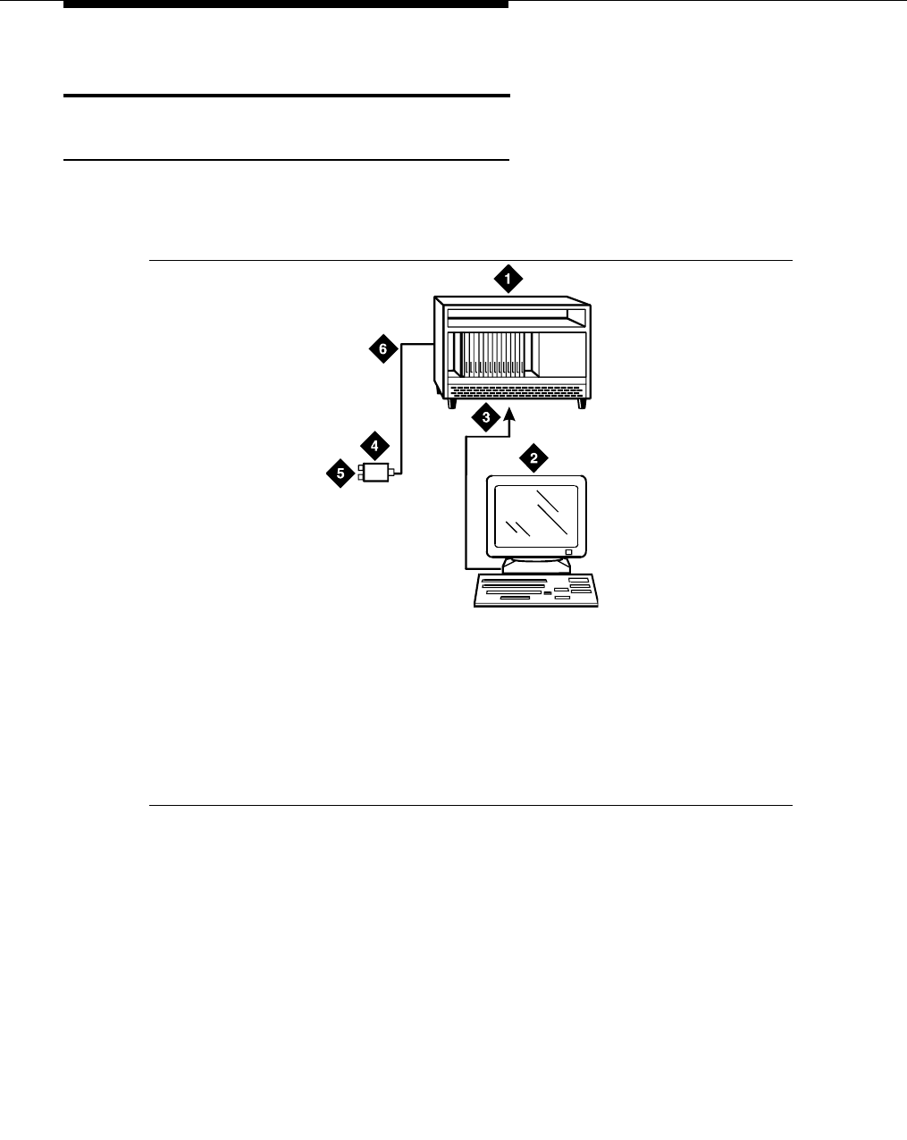
ISDN converters and adapters
555-233-116
158 Issue 4 October 2002
Converters for single-carrier cabinets
PRI-to-DASS and PRI-to-DPNSS converters
Figure 34 shows typical connections from the CCSC-1 PRI-to-DASS converter or
the CCSC-2 PRI-to-DPNSS converters to the coaxial facility.
Figure 34. Typical DASS or DPNSS converter cabling
1. Plug the PC into the RS-232 connector on the front of the PRI converter
circuit pack.
2. Connect the coaxial Y-cable from the TN464F to the PRI converter circuit
pack.
3. Connect the opposite end of the Y-cable to the 888B coaxial converter.
1. To TN464F DS1 circuit pack and
either a CSCC-1 PRI-to-DASS
converter or a CSCC-2 PRI-to-
DPNSS converter circuit pack
2. Administration PC
3. RS-232 cable to front of PRI
converter circuit pack
4. 888B coaxial converter
5. Coaxial connection to 2-Mbps
facility
6. Coaxial cable from PRI converter
circuit pack to coaxial converter
0001 0 RBP 051396

Converters for single-carrier cabinets
Issue 4 October 2002 159555-233-116
PRI-to-BRI converter
Figure 35 shows typical connections from the PRI-to-BRI converter to the coaxial
facility.
Figure 35. Typical PRI to BRI converter cabling
NOTE:
The inset shows details of the cable connections between the circuit packs.
Connect the DEFINITY administration PC to the RS-232 connector on the
front of the PRI converter circuit pack.
1. To TN464F DS1 circuit pack and
PRI-to-BRI converter circuit pack
2. DEFINITY administration PC
3. RS-232 cable to front of converter
circuit pack
4. 888B coaxial converter
5. Coaxial connection to 2-Mbps
facility
6. Coaxial cable from PRI converter
circuit pack to coaxial converter
7. TN464F circuit pack
8. PRI-to-BRI converter circuit pack
9. Jumper coaxial cable
10. Inset showing connections on rear of
carrier
0007_0 RBP 051396
7
(2B+D)
1
(2B+D)
8
(2B+D)
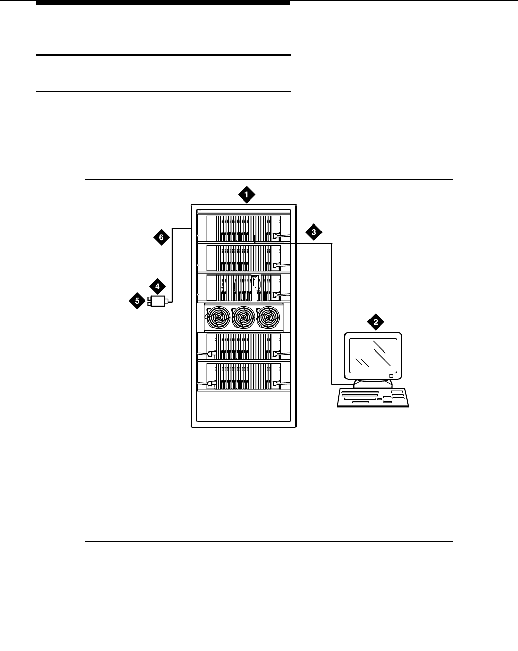
ISDN converters and adapters
555-233-116
160 Issue 4 October 2002
Converters for multi-carrier cabinets
PRI-to-DASS and PRI-to-DPNSS converters
1. Connect the DEFINITY administration PC to the RS-232 connector on the
front of the PRI converter circuit pack.
Figure 36 shows typical connections from the CCSC-1 PRI-to-DASS
converter or the CCSC-2 PRI-to-DPNSS converters to the coaxial facility.
Figure 36. Typical DASS or DPNSS converter cabling
1. To TN464F DS1 circuit pack and
either a CSCC-1 PRI-to-DASS
converter or a CSCC-2 PRI-to-
DPNSS converter circuit pack
2. DEFINITY administration PC
3. RS-232 cable to front of PRI
converter circuit pack
4. 888B coaxial converter
5. Coaxial connection to 2-Mbps
facility
6. Coaxial cable from PRI converter
circuit pack to coaxial converter
ALARMS
EMERTR C
A
R
D
I
N
U
S
E
ENTER
/YES
NEXT
/NO
BACK
AUDIX
BOOT/
SHUTDOWN
0011
_
0 RBP 060696

Converters for multi-carrier cabinets
Issue 4 October 2002 161555-233-116
PRI-to-BRI converter
Figure 37 shows typical connections from the PRI-to-BRI converter to the coaxial
facility. The DEFINITY administration PC is connected to the RS-232 connector
on the front of the PRI converter circuit pack.
Figure 37. Typical PRI to BRI converter cabling
NOTE:
The inset shows details of the cable connections between the circuit packs.
1. TN464F DS1 circuit pack and PR-to-BRI
converter circuit pack
2. DEFINITY administration PC
3. RS-232 cable to front of converter circuit
pack
4. 888B 75-ohm coaxial converter
5. Coaxial connection to 2-Mbps facility
6. Coaxial cable from PRI converter circuit
pack to coaxial converter
7. TN464F circuit pack
8. PRI-to-BRI converter circuit pack
9. Jumper coaxial cable
10. Inset showing connections on rear of
carrier
ALARMS
EMERTR C
A
R
D
I
N
U
S
E
ENTER
/YES
NEXT
/NO
BACK
AUDIX
BOOT/
SHUTDOWN
0022
_
1 PDH 062596
7
(2B+D)
1
(2B+D)
8
(2B+D)

ISDN converters and adapters
555-233-116
162 Issue 4 October 2002

Issue 4 October 2002 163555-233-116
11
Stratum 3 clock
The Stratum 3 clock is an optional feature for digital frame timing that couples the
clock output to local clocks. This chapter provide information on setting the option
switches on the clock. For installation information refer to the appropriate
installation or upgrade book for your system.
NOTE:
The information in this chapter does not apply to the G700 Media Gateway
configurations. There is no way to physically connect the G700 tone clock
(resident on the motherboard) to an external Stratum 3 clock source.
Set clock options
There are four sets of option switches on the clock. Proceed as follows.
1. Set the options on the clock input board (CI) per Table 16.
Table 16. CI Option Switch Settings
Switch Function Position
1 T1 select OFF = enable (default)
ON = disable
2 CC select OFF = enable
ON = disable (default)
3 Framing select OFF = ESF
ON = D4 (default)
4 BX.25 OFF = enable
ON = disable (default)
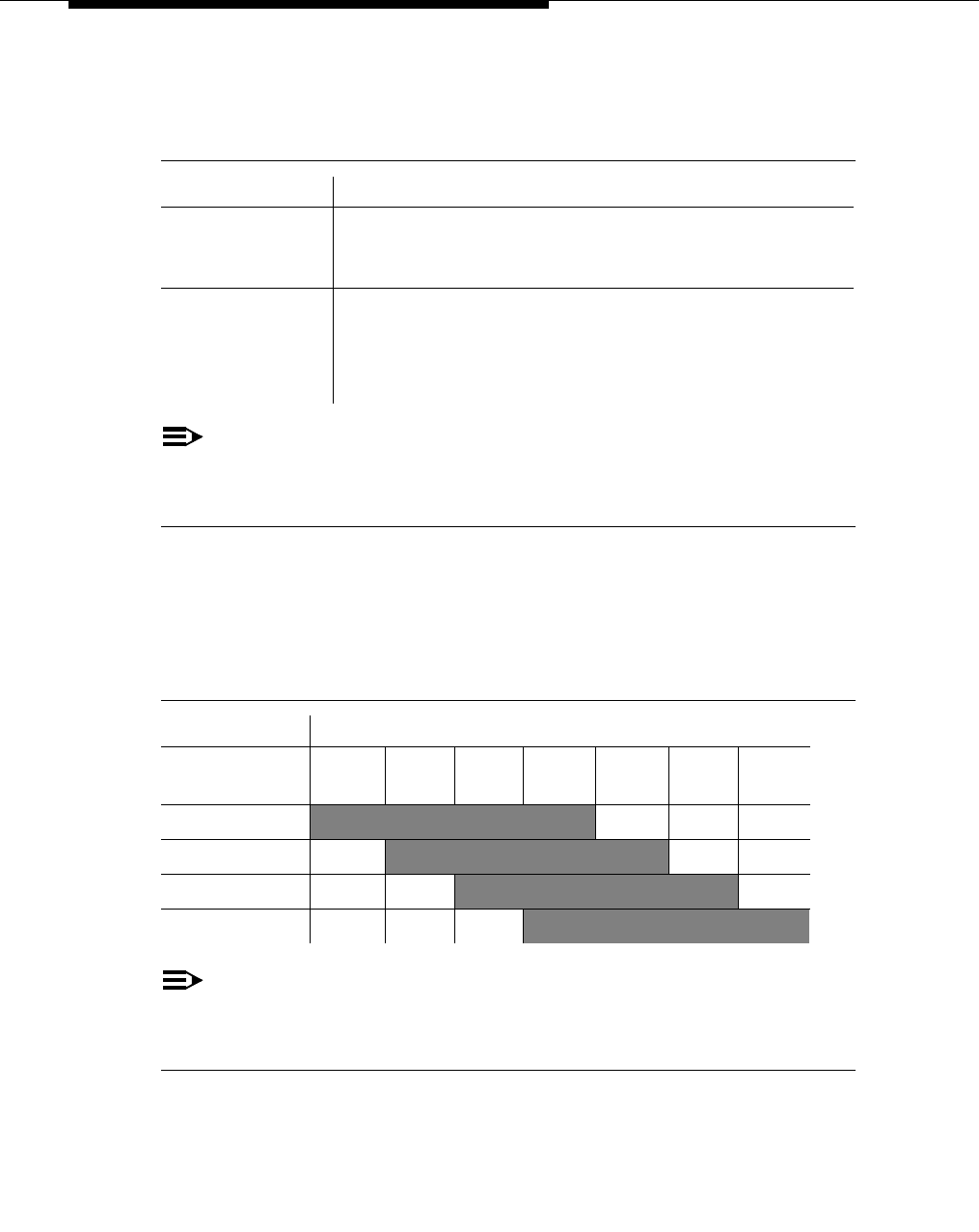
Stratum 3 clock
555-233-116
164 Issue 4 October 2002
2. Set the options on the Stratum 3 (ST3) clock board (see Table 17).
NOTE:
Only SW 1 and SW2 are used. SW1 controls the output of alarm signals
from the Stratum 3 clock board.
3. Set the options on the composite clock timing output board (TOCA) per
Table 18.
4. Set the Stratum 2/Stratum 3 switch to the STRATUM 3 position.
NOTE:
Set switches 1 and 2 according to the distance from the Stratum 3 clock to
the DEFINITY system. Set switch 3 to ON. Set switch 4 to OFF.
Table 17. ST3 clock board option switch settings
Switch Status/Results
SW1
Minor alarm
control
OFF = minor alarm never output
ON = minor alarm is output if holdover occurs
SW2
Major Alarm
Control
OFF = major alarm is output and fail lamp lights if 5 VDC
power is lost and 4 kHz output is lost
ON = major alarm is output and fail lamp lights if 5 VDC
power is lost and 4 kHz output is lost and holdover occurs
Table 18. Composite clock timing output board (TOCA)
Switch Range in feet (meters)
500 1000 1.0
(0.3) 500
(152) 1000
(305) 1500
(457) 2000
(710) 2500
(772) 3000
(914)
OFF OFF
ON OFF
OFF ON
ON ON

Set clock options
Issue 4 October 2002 165555-233-116
Cabling the Stratum 3 clock
Figure 38 shows typical connections to a Stratum 3 clock cabinet. Connections
are made through the yellow field cross-connect. A custom Y-cable (H600-274)
connects the CSU to the DS1 circuit pack and taps off the input for the Stratum 3
clock. A resistor built into the cable to provides the necessary isolation between
the system and the clock. The Y-cable plugs directly into the CSU and connects to
standard cables for interface to the system and the yellow field on the MDF.
The H600-307 cable connects the system end of the Y-cable to a DS1 circuit pack
(shown as TN464F or TN767E). The B25A cable connects the clock end of the
Y-cable to the yellow field on the MDF.

Stratum 3 clock
555-233-116
166 Issue 4 October 2002
Figure 38. Typical connections to Stratum 3 clock
The H600-307 cable connects the system end of the Y-cable to a DS1 circuit pack
(shown as TN464 or TN767E). The B25A cable connects the clock end of the
Y-cable to the yellow field cross-connect.
1. PPN cabinet
2. “A” position
3. “B” position
4. H600-307 cable
5. H600-274, G2 cable
6. 1300 ft. (397 m)
7. B25A male to female cables
8. Secondary CSU
9. Primary CSU
10. Stratum 3 Clock
11. MDC
12. TN464F DS1/E1 interface circuit pack
13. TN767E DS1 circuit pack
14. TN780 tone-clock circuit pack
cydfst3 KLC
0
1
1
2
2
3
3
4
4
4
4
5
5
5
5
6
6
7
7
7
7
7
7
7
7
7
8
8
9
9
10
10
11
11
12
12
13
13
14
14
14

Set clock options
Issue 4 October 2002 167555-233-116
Stratum 3 clock wiring installation procedure
1. Connect the B25A cables from the TN780 connector panel slot on the
system cabinet and the Stratum 3 Clock to the cross-connect module in the
yellow field.
2. Connect the CSU plug end of the H-600-274 Y-cable to the primary CSU.
Route an H600-307 cable from the DS1 connector panel slot on the system
cabinet to the connector on the “SYSTEM” end of the Y-cable.
3. Route a B25A cable from the “CLOCK” end of the Y-cable to the cross-
connect module in the yellow field.
4. Repeat steps 2 and 3 for the secondary CSU. The maximum allowable
cabling distance between the Stratum 3 clock and the CSU is shown in the
table below.
5. For standard reliability systems, refer to Y-cable to cross-connect the
TN780 and “CLOCK” end connections to the Stratum 3 clock connections
on the cross-connect module.
6. For high or critical reliability systems, refer to table below to cross-connect
the TN780 and “CLOCK” end connections to the Stratum 3 clock
connections on the cross-connect module.
Table 19. Maximum cabling distance for different CSUs
Channel Service Unit (CSU) Maximum Cabling Distance
551A 85 feet (27 m)
551V 85 feet (27 m)
551V EFS/R 755 feet (199.7 m)
EFS T1 755 feet (199.7 m)
Table 20. Y-cable clock-end cross-connects for reliability
From Stratum 3 Clock
To Y-cable clock end
(primary)
To Y-cable clock end
(secondary)
Lead
Name
Lead Color/
Terminal
Lead
Name
Lead Color/
Terminal
Lead
Name
Lead Color/
Terminal
RREF1 W-BL/1 V-O/43
TREF1 BL-W/2 O-V/44
RREF2 W-O/3 V-O/43
TREF2 O-W/4 O-V/44

Stratum 3 clock
555-233-116
168 Issue 4 October 2002
Table 21. TN780-carrier cross-connects for standard reliability
From Stratum 3 Clock To TN780 carrier A To TN780 carrier B
Lead
Name
Lead Color/
Terminal
Lead
Name
Lead Color/
Terminal
Lead
Name
Lead Color/
Terminal
BCLKRTN R-O/13 ALRM5B V-G/45
BCLKLST O-R/14 ALRM5A G-V/47
BPWRRTN R-BR/17 ALRM4B BK-BL/21
BPWRLST BR-R/18 ALRM4A BL-BK/22
REF2RTN W-BR/7 ALRM3B R-BR/17
REF2LST BR-W/8 ALRM3A BR-R/18
SCLKRTN R-BL/11 ALRM2B R-BL/11
SCLKLST BL-R/12 ALRM2A BL-R/12
SPWRRTN R-G/15 ALRM1B Y-BL/31
SPWRLST G-R/17 ALRM1A BL-Y/32
BCLKRTN R-O/13 ALRM5B V-G/45
REF1RTN W-G/5 ALRM0B W-BR/7
REF1LST G-W/7 ALRM0A BR-W/8
CCA01R R-S/19 EXTSYN0T V-BL/41
CCA01T S-R/20 EXTSYN0R BL-V/42
CCB01R BK-BL/21 EXTSYN1T Y-G/35
CCB01T BL-BK/22 EXTSYN1R G-Y/37
Continued on next page

Set clock options
Issue 4 October 2002 169555-233-116
Table 22. Y-cable clock-end cross-connects for high or critical reliability
From Stratum 3 Clock
To Y-cable clock end
(primary)
To Y-cable clock end
(secondary)
Lead
Name
Lead
Color/
Terminal
Lead
Name
Lead Color/
Terminal
Lead
Name
Lead Color/
Terminal
RREF1 W-BL/1 V-O/43
TREF1 BL-W/2 O-V/44
RREF2 W-O/3 V-O/43
TREF2 O-W/4 O-V/44
Continued on next page
Table 23. Circuit-pack cross-connects for high or critical reliability
From Stratum 3 Clock To TN780 carrier A To TN780 carrier B
Lead
Name
Lead Color/
Terminal
Lead
Name
Lead Color/
Terminal
Lead
Name
Lead Color/
Terminal
BCLKRTN R-O/13 ALRM5B V-G/45 ALRM5B V-G/45
BCLKLST O-R/14 ALRM5A G-V/47 ALRM5A G-V/47
BPWRRTN R-BR/17 ALRM4B BK-BL/21 ALRM4B BK-BL/21
BPWRLST BR-R/18 ALRM4A BL-BK/22 ALRM4A BL-BK /22
REF2RTN W-BR/7 ALRM3B R-BR/17 ALRM3B R-BR/17
REF2LST BR-W/8 ALRM3A BR-R/18 ALRM3A BR-R/18
SCLKRTN R-BL/11 ALRM2B R-BL/11 ALRM2B R-BL/11
SCLKLST BL-R/12 ALRM2A BL-R/12 ALRM2A BL-R/12
SPWRRTN R-G/15 ALRM1B Y-BL/31 ALRM1B Y-BL/31
SPWRLST G-R/17 ALRM1A BL-Y/32 ALRM1A BL-Y/32
REF1RTN W-G/5 ALRM0B W-BR/7 ALRM0B W-BR/7
REF1LST G-W/7 ALRM0A BR-W/8 ALRM0A BR-W/8
CCA01R R-S/19 EXTSYN0T V-BL/41
CCA01T S-R/20 EXTSYN0R BL-V/42
Continued on next page

Stratum 3 clock
555-233-116
170 Issue 4 October 2002
7. Bridge the jumper wires to cross-connect from the TN780 in A and B
carriers to the Stratum 3 clock.
8. Dress the cables down sides of the cabinet and run through the cable
Slack Manager, if provided.
9. Administer the switch for the clock.
CCB01R BK-BL/21 EXTSYN1T Y-G/35
CCB01T BL-BK/22 EXTSYN1R G-Y/37
CCA02R BK-O/23 EXTSYN0T V-BL/41
CCA02T O-BK/24 EXTSYN0R BL-V/42
CCB02R BK-G/25 EXTSYN1T Y-G/35
CCB02T G-BK/26 EXTSYN1R G-Y/37
Table 23. Circuit-pack cross-connects for high or critical reliability — Continued
From Stratum 3 Clock To TN780 carrier A To TN780 carrier B
Lead
Name
Lead Color/
Terminal
Lead
Name
Lead Color/
Terminal
Lead
Name
Lead Color/
Terminal
Continued on next page

Issue 4 October 2002 171555-233-116
12
Busy tone disconnect equipment for
non-U.S. installations
The customer-provided busy tone disconnect adjunct detects disconnects of
incoming calls on loop-start, 2-wire, analog trunks. In some countries outside the
United States, the PSTN sends tones in the voice band instead of line disconnect
signals. Figure 39 shows typical connections.
NOTE:
The busy tone disconnect feature is not currently supported on a
G700 Media Gateway.
Figure 39. Typical cabling for busy tone disconnect
1. Public switched telephone network
2. Main distribution frame
3. Busy tone disconnect device
4. Tip and ring wires
5. To loop-start, central-office, trunk
circuit pack such as a TN747B
cydf057 RPY 123097
1
2 2
3
4 4 4
5

Busy tone disconnect equipment for non-U.S.
installations
555-233-116
172 Issue 4 October 2002

Issue 4 October 2002 173555-233-116
13
Call detail recording (CDR) option
settings
This chapter provides information on connecting call detail recording (CDR)
equipment to a DEFINITY Server (such as an MCC1 Media Gateway), and to a
G700 Media Gateway.
Connecting CDR equipment
The interface between an Avaya media server and CDR equipment may be a:
■Data module (see Chapter 4, ‘‘Data modules and asynchronous data
units’’, for recommended settings).
■Modem (see Chapter 5, ‘‘External modems’’, and the modem vendor’s
documentation for recommended settings).
■TN726 data line circuit pack and an asynchronous data unit.
NOTE:
The TN726 data line circuit pack is not supported in either multi-
connect or IP-connect implementations of the S8700 Media Server.
TN726 data line circuit packs are only supported on DEFINITY G3r
and earlier platforms.
■TCP/IP connection to the C-LAN board on an MCC1 Media Gateway, or to
the IP connection on an G700/S8300 server configuration, either directly or
through a terminal server (see Chapter 8, ‘‘Terminal server installation’’ for
more information on connecting through a terminal server).
CDR equipment can connect directly to the DCE connector — the Electronic
Industries Association (EIA) port — on the rear of the control carrier in all systems
except G3csi. Data modules or modems are not required. In the G3csi, CDR
equipment connects to the DCE (J2) connector on the processor interface cable.

Call detail recording (CDR) option settings
555-233-116
174 Issue 4 October 2002
On a G700/S8300 server configuration, CDR equipment can connect to one of the
two IP connections (EXT 1 or EXT 2) on the front of the G700 Media Gateway.
NOTE:
You can also use any of the ports on an optional 16-port module, if your
G700 Media Gateway is so equipped.
Using other equipment as the CDR
output devices
A printer, a 94A local storage unit (LSU), or customer premises equipment (CPE)
can be used as the output receiving device.
Sources of administration information
Administration procedures for CDR equipment are provided in Administrator’s
Guide for Avaya MultiVantage Software.
Connecting a CDR device
This section provides information on connecting adjuncts to the media server, and
providing the initial administration.
Task list
Whether you use an end-to-end TCP/IP configuration, a terminal server or a PC
running RSP, you must complete the following tasks:
■‘‘Administering IP node names’’ on page 131
■‘‘Administering IP services’’ on page 132
■‘‘Administering CDR parameters’’ on page 174
■If you are using a terminal server, also complete ‘‘Installing and
administering the terminal server’’ on page 122
■If you are using a PC with the Downloadable RSP Tool, complete ‘‘Using
the downloadable reliable session-layer protocol (RSP) tool’’ on page 176
Administering CDR parameters
You must administer adjunct parameters to let the system know that the adjunct is
connected through TCP/IP.
1. Type change system-parameters cdr and press RETURN.

Connecting a CDR device
Issue 4 October 2002 175555-233-116
The CDR System Parameters screen appears.
2. In the Primary Output Endpoint field, type CDR1. If you use a
secondary output device, and that device is also connected through TCP/
IP, type CDR2 in the Secondary Output Endpoint field.
3. Press ENTER to save your changes.
Testing the switch-to-adjunct link
You can use the test, status, busyout and release commands for to find and
correct problems with CDR links. For more information about these commands,
see the Maintenance manual for your switch.
You should also work with the vendor to test the link from the call accounting end.
If you are installing the INTUITY Lodging Call Accounting, work with the Homisco
technician to test the link.
If a link does not come up immediately, try using the busyout cdr-link and release
cdr-link commands.
change system-parameters cdr Page 1 of 1
CDR SYSTEM PARAMETERS
Node Number (Local PBX ID): CDR Date Format: month/day
Primary Output Format: printer Primary Output Endpoint: CDR1
Secondary Output Format:
Use ISDN Layouts? n EIA Device Bit Rate: 9600
Use Enhanced Formats? n Condition Code ‘T’ for Redirected Calls? n
Modified Circuit ID Display? n Remove # From Called Number? n
Record Outgoing Calls Only? y Intra-switch CDR? n
Suppress CDR for Ineffective Call Attempts? y CDR Call Splitting? y
Disconnect Information in Place of FRL? n Attendant Call Recording? y
Interworking Feat-flag? n
Force Entry of Acct Code for Calls Marked on Toll Analysis Form? n
Calls to Hunt Group - Record: member-ext
Record Called Vector Directory Number Instead of Group or Member? n
Record Called Agent Login ID Instead of Group or Member? n
Inc Trk Call Splitting? n
Record Non-Call-Assoc TSC? n
Record Call-Assoc TSC? n Digits to Record for Outgoing Calls: dialed
Privacy - Digits to Hide: 0 CDR Account Code Length: 4
status cdr-link
CDR LINK STATUS
Primary Secondary
Link State: up extension not administered
Maintenance Busy? no

Call detail recording (CDR) option settings
555-233-116
176 Issue 4 October 2002
Using the downloadable reliable
session-layer protocol (RSP) tool
The intent of the reliable session-layer protocol (RSP) is to guarantee delivery of
data records from the switch to an output device that connects to the switch over
an asynchronous TCP/IP link. You can download the RSP tool from the Avaya
Web site. The RSP tool allows you to implement this protocol on a PC that
collects data records in a file. The protocol assures that the data records arrive
safely at the PC. You can then send the output file to a printer.
Setting up an RSP configuration
To set up an RSP configuration:
■Administer the PC as a client application on the switch.
■Download, install, and administer the RSP for the PC.
Setting up the switch
To set up the server application on the switch, complete the following tasks:
■‘‘Administering IP node names’’ on page 131
Give the PC a node name. The IP address is the IP address of the PC that
is running the RSP tool.
■‘‘Administering IP services’’ on page 132
The service type = SYS_PRNT, the Remote Node = the node name
assigned to the PC. Remote port is the port assigned as the listen port on
the PC. You can determine the listen port by starting the RSP Server
application, clicking on Start, and checking in the output window to see
what port the server is listening on.
Setting up the PC
To set up the client application on the PC you will be:
■‘‘Downloading RSP’’
■‘‘Installing RSP’’
■‘‘Administering RSP’’

Using the downloadable reliable session-layer protocol
(RSP) tool
Issue 4 October 2002 177555-233-116
Downloading RSP
The RSP is available from the Avaya support Web site as a self-extracting
executable. To download the RSP:
1. Go to the Avaya Customer Support Web site at http://avaya.com/support.
2. In the Search For text box, type reliable and click Go.
3. Select the RSP tool from the Web site.
4. When asked, save the setup.exe file to a temporary folder on your
computer. It is approximately 1.4-MB.
Installing RSP
To install the RSP:
1. Double-click the setup.exe file.
The Install Shield Wizard steps you through the installation.
2. When prompted to select Client or Server, select both programs.
3. Continue with the installation. Use the default destination folder and
program folder.
Administering RSP
See the instructions in the user guide.doc file to administer the reliable session-
layer protocol (RSP) on a PC.

Call detail recording (CDR) option settings
555-233-116
178 Issue 4 October 2002

Issue 4 October 2002 179555-233-116
14
DEFINITY INADS
The DEFINITY® initialization and administration system (INADS) provides analog
loopback connections and PARTNER connections for remote alarming and
maintenance when direct connection to the public network is not possible.
NOTE:
These instructions are for Avaya Media Server or Gateway systems using
the TN1648/B system access/maintenance (SYSAM) circuit pack. ISDN is
required. These instructions do not apply to the S8300 or the S8700 Media
Servers in a G700 Media Gateway configuration.
Analog loopback
Analog loopback connects the INADS port to an analog station port. It switches
the call through the AUX connector on the processor carrier, across an analog line
circuit pack, and out to the public network. Direct Inward Dialing (DID) is optional.
Installing INADS analog loopback on a
standard-reliability system
1. Connect the INADS tip and ring port from the AUX connector to an analog
station port through the MDF. See Figure 40. Use wire pair 50 and 25.
2. If you are using power fail transfer, connect the 808A2 transfer panel
between the INADS connection to the station and the INADS connection to
the loop-start trunk.
NOTE:
The 808A power fail transfer unit is not supported on the G700 Media
Gateway.
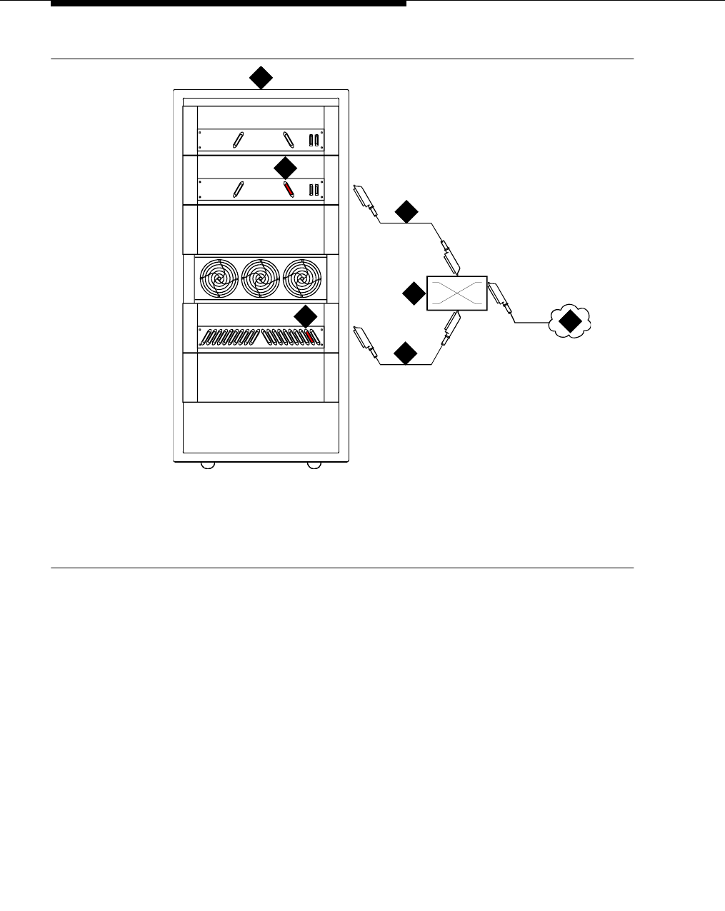
DEFINITY INADS
555-233-116
180 Issue 4 October 2002
Figure 40. Analog loopback connections
Installing INADS analog loopback on a
high-reliability system
Be sure to place the TN1648B SYSAM circuit packs in different cabinets or
processor carriers. Also be sure to place the analog line circuit packs in the same
cabinets or carriers as the TN1648 circuit packs.
1. Connect each INADS tip/ring port to an analog station port through the
MDF. See Figure 40.
2. Connect each tip/ring port to a separate analog line circuit pack.
1. Avaya Media Server or Gateway PPN
2. AUX connector on processor carrier
(use wire pair 50 and 25, tip and ring)
3. Port carrier (with analog line circuit pack)
4. B25A 25-pair cable to AUX
5. Main distribution frame (MDF)
6. B25A 25-pair cable to circuit pack
7. PSTN or extension
cydfmdf RPY 040698
1
4
6
5
3
2
7

DEFINITY INADS
Issue 4 October 2002 181555-233-116
Administration
NOTE:
Add 2 pauses in front of the dial string when using cut-through trunks.
Pauses are not required if using ARS.
1. Type change system-parameters maintenance and press Enter.
2. For high reliability systems, in the see interchange: field, type daily
and press Enter. This is done in case 1 of the connections between the 2
TN1648B circuit packs is down. This assures that within 24 hours the
working connection is available to report alarms.
3. Type add station number or next and press Enter.
4. In the Type field, enter 500 (rotary analog telephone).
5. In the Port field, enter the port number for this line.
6. For high reliability systems, repeat the above steps for the second analog
line. Administer the 2 stations as part of a TEG (terminating extension
group).
a. Type add term-ext-group number or next and press Enter.
b. In the Group Extension field, enter the TEG extension number.
c. In the Coverage Path field, enter the coverage path number.
d. Enter the Group Member Assignment station numbers.
e. Press Enter when finished.
Partner installation
The PARTNER system connects the INADS port to an outgoing central office
(CO) line and is programmed to seize the outside line when INADS seizes an
inside PARTNER station line.
There are 2 types of PARTNER platforms:
■PARTNER Atlas platforms with U.S. firmware and a wide input power
supply (WIPS) that allows a universal power supply. The Spain platform
conforms to the United States/Atlas platform
■European platforms that focus on eastern Europe and the United Kingdom
The installation procedure describes the 2 types of PARTNER platforms with or
without power fail transfer.
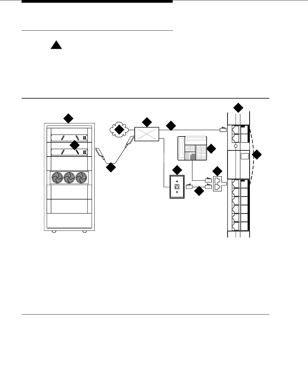
DEFINITY INADS
555-233-116
182 Issue 4 October 2002
INADS connection with power fail transfer
!CAUTION:
Check local regulations regarding this connection method.
In this configuration, the INADS line and the emergency telephone extension are
bridged together. Figure 41 shows the U.S./Atlas platform. Figure 42 shows the
European platform.
Figure 41. INADS connection (US/Atlas platform)
1. PARTNER System
2. MLS12D telephone for programming
3. Internal connection during power failure,
from CO line port 1 to station port 10
4. 258A adapter (bridged connection)
5. Standard RJ-45 telephone cord
6. 103A or modular wall jack
7. Dial tone from CO or DEFINITY
extension
8. Main distribution frame
9. PSTN or DEFINITY extension
10. B25A 25-pair cable to AUX
11. AUX connector (use wire pair 50 and 25,
tip and ring)
12. Avaya Media Server or Gateway PPN
cydf206 RPY 021998
1
L
I
N
E
S
E
X
T
E
N
S
I
O
N
S
PFT
PFT
206
MODULE
R2.0
4
5
12
11
10 6
3
7
8
2
9
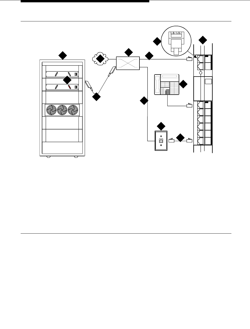
DEFINITY INADS
Issue 4 October 2002 183555-233-116
Figure 42. INADS connection (European platform)
Standard reliability
■Normal connection: Connect the INADS tip and ring port from the AUX
connector (wire pair 50 and 25) to the tip/ring pair of CO line port 1 on the
PARTNER system.
■US/Atlas/Spain platform connection: Connect station 10 to the INADS
port.
■European platform connection: Bridge the outside pair of CO line port 1
to the INADS port. A 258A adapter may be used.
1. PARTNER System
2. MLS12D telephone for programming
3. Standard RJ-45 telephone cord
4. 103A or modular wall jack
5. Pins 2,3 on cable 5 bridge to pins 1,4
of cable 7 inside MDF
6. Dial tone from the CO or extension on
pins 2,3; with return dial tone to the
INADS port on pins 1,4 during power
failure
7. Main distribution frame (MDF)
8. PSTN or switch extension
9. B25A 25-pair cable to AUX
10. AUX connector (use wire pair 50,25, tip and
ring)
11. Avaya Media Server or Gateway PPN
12. Standard RJ-45 connector (pins 2,3, tip and
ring, connect to pins 1,4, tip and ring, when
the internal contacts close during power
failure)
1
L
I
N
E
S
E
X
T
E
N
S
I
O
N
S
PFT
PFT
206
MODULE
R2.0
cydf206a RPY 02199
8
9
4
5
2
7
3
6
12
10
11
1234
8
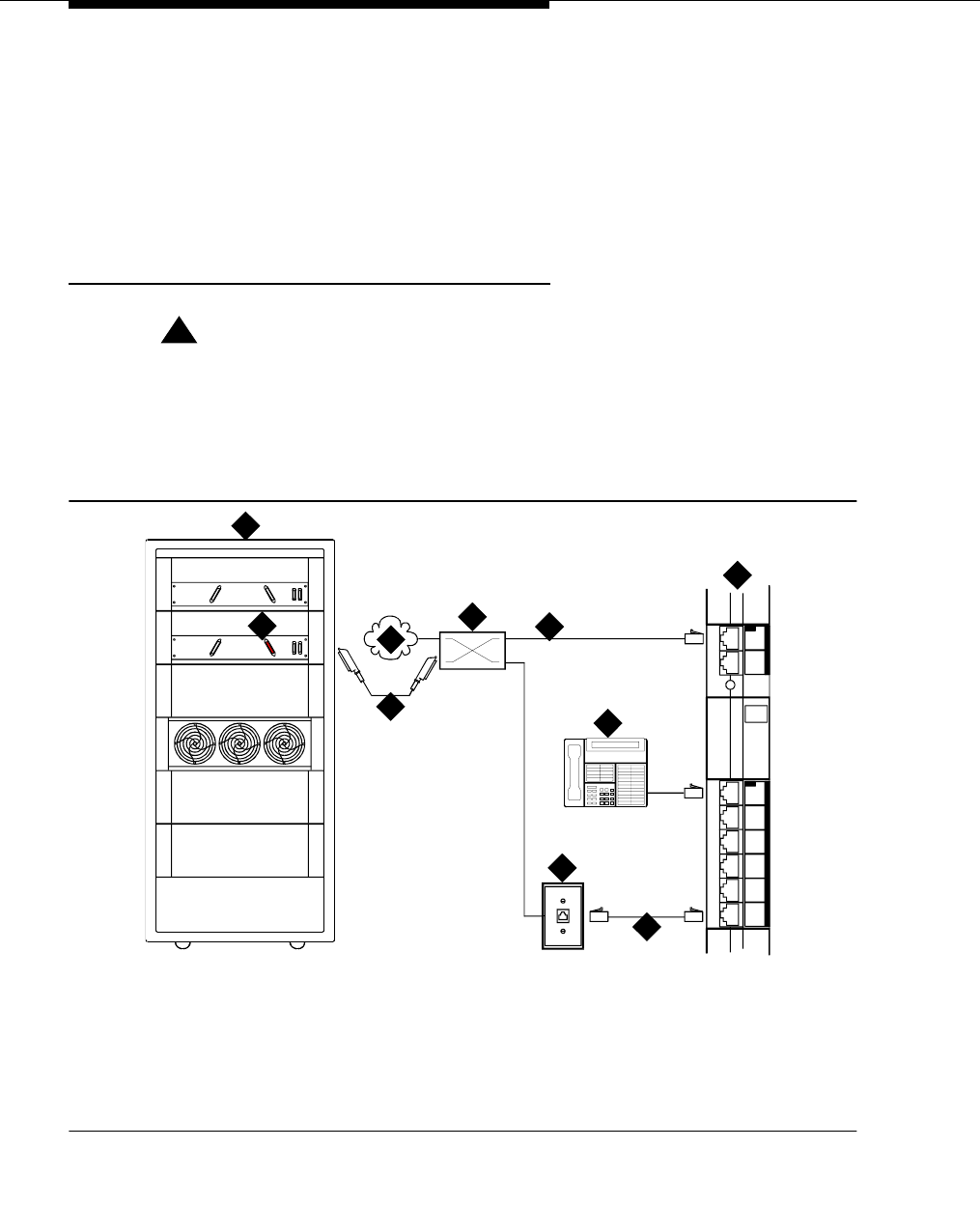
DEFINITY INADS
555-233-116
184 Issue 4 October 2002
High reliability
Be sure that the TN1648B SYSAM circuit packs are located in different DEFINITY
cabinets or processor carriers.
1. Bridge the 2 INADS tip/ring ports. A 258A adapter may be used.
2. Connect the bridged INADS tip/ring port to a PARTNER station port.
INADS connection without power fail transfer
!CAUTION:
Check local regulations regarding this connection method.
In this configuration (Figure 43), the INADS line and the emergency telephone
extension are bridged together. If this connection method is not allowed, do not
connect the INADS port to station 10.
Figure 43. INADS connection (all platforms)
1. PARTNER system
2. MLS12D telephone for programming
3. Standard RJ-45 telephone cord
4. 103A or modular wall jack
5. Dial tone from the CO or a switch
extension
6. Main distribution frame
7. PSTN
8. B25A 25-pair cable
9. AUX connector (use wire pair 50,25, tip
and ring)
10. Avaya Media Server or Gateway PPN
cydf206b RPY 021998
1
L
I
N
E
S
E
X
T
E
N
S
I
O
N
S
PFT
PFT
206
MODULE
R2.0
4
5
10
9
3
7
82
6

DEFINITY INADS
Issue 4 October 2002 185555-233-116
Standard reliability
Normal connection:
1. Connect a system telephone to station 10 on the PARTNER system.
2. Connect a standard RJ-11 telephone line cord from the PARTNER CO line
to the CO line protector.
3. Connect the INADS tip and ring port from the AUX connector to the tip/ring
pair of CO line port 1 on the PARTNER through the MDF. See Figure 43.
Use wire pair 50 and 25 on the MDF.
U.S./Atlas/Spain platform connection:
1. Select station 11-15 as the INADS port connection.
European platform connection:
1. Bridge the outside pair of CO line port 1 to the INADS port. A 258A adapter
may be used.
High reliability
Be sure that the TN1648B SYSAM circuit packs are located in different cabinets
or processor carriers.
1. Bridge the 2 INADS tip/ring ports. A 258A adapter may be used. See
Figure 43.
2. Connect the bridged INADS tip/ring port to a station port.
PARTNER administration
Set standard telephone station (European
platforms only)
NOTE:
Do not exit from the programming mode until instructed to do so.
1. Connect the PARTNER programming telephone (MLS12) to station 10.
2. Press Feature, followed by 0 0.
3. Press the left intercom (System Program) button twice.
4. Enter the password. The default password is 7777. The green LED next to
the left intercom button must be steady on.
5. Enter # 3 0 8.
6. Enter 1 0 (if station 10 is connected to the INADS port) or the station
number connected to the INADS port.

DEFINITY INADS
555-233-116
186 Issue 4 October 2002
7. Enter 2 to set the station port to analog rotary. Enter 1 if an analog DTMF
telephone or PARTNER system telephone is connected.
8. Enter # to return to the start of the programming mode.
Set PARTNER CO line port (all platforms)
1. Enter # 2 0 1.
2. Press 1 for tone or 2 for pulse mode.
3. Enter # to return to the start of the programming mode.
Set automatic line selection — outgoing trunk
(all platforms)
1. Press the right intercom (Central Tel Program) button.
2. Enter 1 5 (if INADS is connected to station 15) or enter the station number
connected to the INADS port.
3. Enter * *.
4. Press the line 1 button (above left intercom). If the 2 lines are connected to
the PARTNER for added reliability or security, press Next Procedure.
5. Enter * *.
6. Enter # to return to the start of the programming mode.
Set incoming line ringing (all platforms)
1. Press the right intercom (Central Tel Program) button.
2. Enter 1 5 (if INADS is connected to station 15) or enter the station number
connected to the INADS port.
3. Press the line 1 button (above left intercom) until the LED changes to a
steady green. This allows incoming calls to ring on line 1.
4. If AUDIX is installed, press the line 2 button until the LED changes to a
steady green. This allows incoming calls to ring on line 2.
5. Enter # to return to the start of the programming mode.
6. Press Feature, followed by 0 0 to exit the programming mode.
DEFINITY ECS administration
By default, the INADS port automatically seizes an outgoing trunk on the
PARTNER system. Therefore, a “9” is not required in the switch dial string.

DEFINITY INADS
Issue 4 October 2002 187555-233-116
Installation test (all installations)
These tests confirm that the hardware and administration are correct.
1. Place an outgoing call from the INADS port. Check for normal talk path.
2. Place an incoming call to the INADS port. Check for normal talk path.
3. Place an outgoing data from the INADS port to verify connection.
A failure in the link between the remote service center and the TN1648Bs INADS
port can be detected automatically.
1. Type change system-parameters maintenance and press Enter.
2. Set the Test Remote Access Port field to y and press Enter.
Connectivity for INADS on S8700 and
S8300 media servers
Prior to visiting the customer premises, technicians and/or customer account
teams should retrieve from the auto registration tool (ART) a script for each
server being registered — two for S8700 and one for S8300. Each script contains
the steps that need to be executed to turn on dial out alarming, as well as the RAS
IP address to be administered for each modem.
Once on site, to enable dial out alarming on the S8700/S8300 platforms, use the
sequence of commands exactly as entered in the script. The RAS IP addresses
for the modems should be administered through the “Configure Server” option on
the Web interface.
NOTE:
You must administer the RAS IP address and dial out information on each
server.
Example of an ART script file
NOTE:
RAS IP address: 10.1.1.27.
Enter the IP address through the Web user interface.
For more information, see Installation and Upgrades for the Avaya G700 Media
Gateway controlled by an Avaya S8300 Media Server or an Avaya S8700 Media
Server, 555-234-100.
productid -p 100003151 The product id will be different for each server.
almenable -d f This command enables dial out on the first phone number
administered.
almcall -f 18005353573 This command administers the phone number.

DEFINITY INADS
555-233-116
188 Issue 4 October 2002
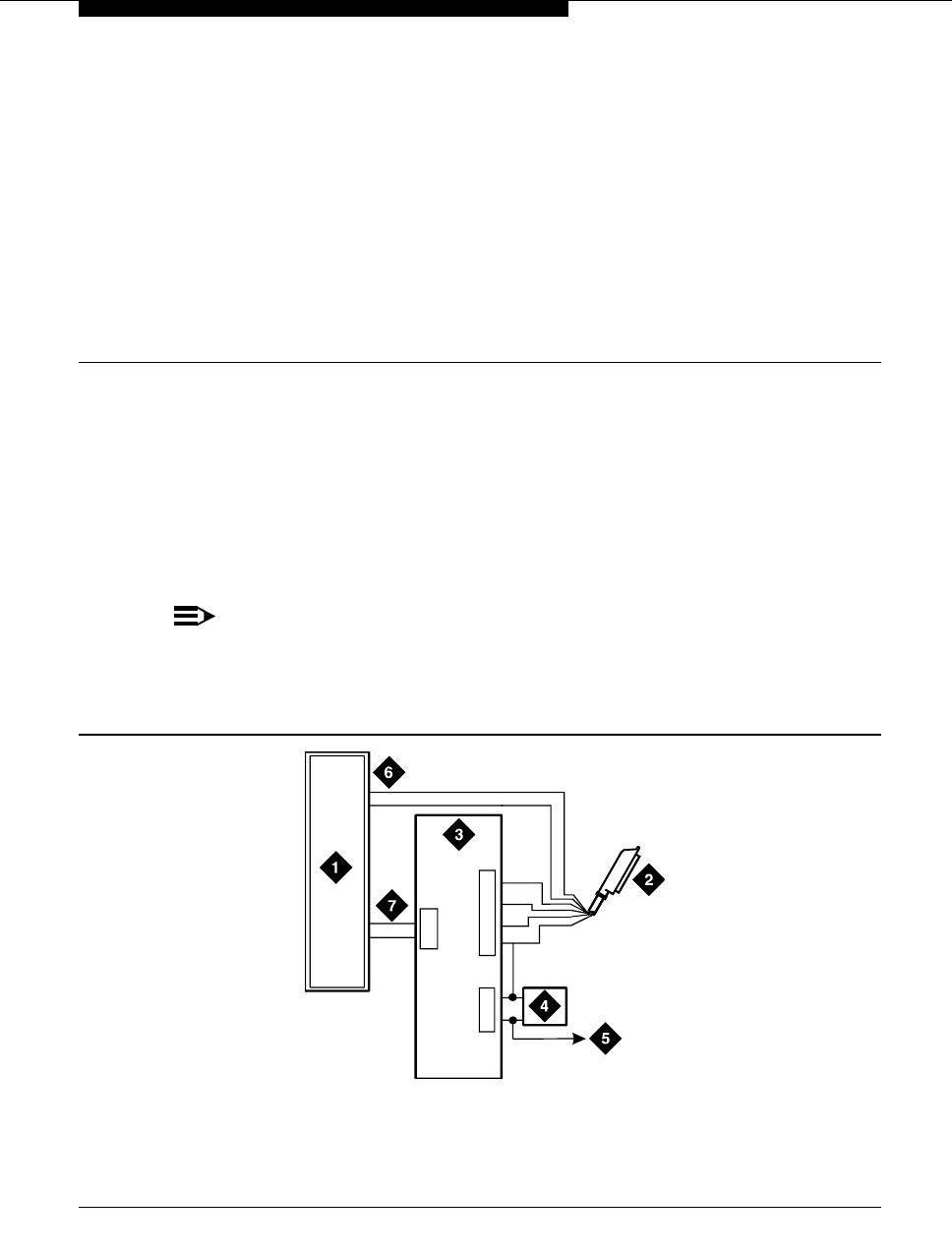
Issue 4 October 2002 189555-233-116
15
Malicious call trace
The malicious call trace (MCT) voice recorder connects directly to the tip and ring
connections of a TN763/D auxiliary trunk circuit pack. See Figure 44. The 909A/B
universal coupler provides seizure control to the recorder.
NOTE:
There is no auxiliary trunk circuit pack for the G700 Media Gateway, so
information in this chapter does not apply to the G700 Media Gateway.
However, you can access MCT equipment connected to a port network.
Figure 44. Malicious call trace
1. Malicious call trace voice recorder
2. 25-pair cable (T, R, S, S1, Sz, SZ1) to
TN763/D auxiliary trunk circuit pack
3. 909A/B universal coupler
4. Power supply for universal coupler
5. To SZ1 on TN763/D connector
6. Tip and ring wires
7. CBS1/C1 and CBS2/C2
c
y
df038 PDH 091696
J2
J3
J1
5
2
7
7
82
3
6

Malicious call trace
555-233-116
190 Issue 4 October 2002
NOTE:
A wiring block must be locally engineered.
NOTE:
909A couplers ships with one DW4B-DE cable and two DW8B-SE cables.
The 909B ships with one KS-22911L2 power supply, one DW4B-DE cable,
and two DW8B-SE cables.
1. Determine the port assignment of the recorder from the malicious call
tracing form.
2. Install the 909A/B universal coupler on a vertical surface.
3. Connect the SZ, SZ1, S, and S1 leads from the 909A/B to an auxiliary trunk
circuit pack.
a. Tip and ring connect from the voice recorder to the auxiliary trunk
circuit pack (J1 on the 909A/B).
b. CBS1/C1 and CBS2/C2 connect from the voice recorder to J2 on
the 909A/B.
4. On the 909A/B universal coupler:
a. Connect seizure control voltage of from -9 to -70 Volts to the PG2/
BZ2 connection (pin 2 of J1). Switching voltage to the PG2/BZ2
connection can be from the 909A/B -48 VDC supply.
b. Connect SZ1 to the ground lead of the DC power source used for
PG2/BZ2.
c. Set S1 to the “C2” position. Set S2 position 7 to “OPEN”.
d. Connect an approved -48 VDC power source to the -48 and GRD
terminals (pins 5 and 2, respectively, of J3 on the 909A/B).
5. Administer the switch for the call trace device.

Issue 4 October 2002 191555-233-116
16
Music-on-hold
The music-on-hold (MOH) feature allows a caller to hear music when that caller is
placed on hold. Depending on the media gateway, music-on-hold can be
provided:
■through a two-wire TN2183 analog line circuit pack (or equivalent) or
auxiliary trunk circuit pack to a customer-supplied music source on an
MCC1, SCC1, CMC1, or G600 Media Gateway.
■through a port on an MM711 Analog Media Module to a customer-supplied
music source on a G700 Media Gateway.
For MCC1, SCC1, CMC1, and G600
Media Gateways
Figure 45 shows the connections for music-on-hold, dial dictation, or recorded
announcement features when the music source is Federal Communications
Commission (FCC) registered (or equivalent). Figure 46 shows the connections
when the music source is not FCC-registered (or equivalent).
Local music-on-hold allows one music source. However, if you purchase the
multiple music-on-hold (tenant partitioning) feature, you can have up to 100 music
sources.
NOTE:
Use the following connection instructions when the music source is not
located in the equipment room. If the music source is located in the
equipment room, do not route the connections through the information
outlet.

Music-on-hold
555-233-116
192 Issue 4 October 2002
Figure 45. Typical registered equipment connections (auxiliary access) for an MCC1,
SCC1, CMC1, or G600 Media Gateway
1. If the music source is registered, the system side of the MDF connects
directly to the system.
2. If the music source is not registered, the system side of the MDF connects
to a 909A/B universal coupler (see Chapter 1, ‘‘909A/B universal coupler’’).
Registered music source
Refer to Figure 45 to install a registered music source.
1. Determine feature port assignment from Feature-Related System
Parameters form.
2. Install music source according to the manufacturer’s instructions.
3. Install patch cord/jumper wires at the main distribution frame.
4. Administer the switch for the new equipment.
Nonregistered music source
Refer to Figure 46 and Figure 47 when installing a nonregistered music source.
1. Determine feature port assignment from Feature-Related System
Parameters Form.
2. Install the music source according to the manufacturer’s instructions.
1. Music source
2. 4-pair modular cord
3. 103A or modular wall jack
4. 122A music adapter (if required—primarily
required in France)
5. Tip (green) and ring (red)
6. Part of main distribution frame
7. A25D 25 pair cable (male-to-male) to
auxiliary trunk circuit pack
cydfmusc RPY 090397
1
2
34
56
7
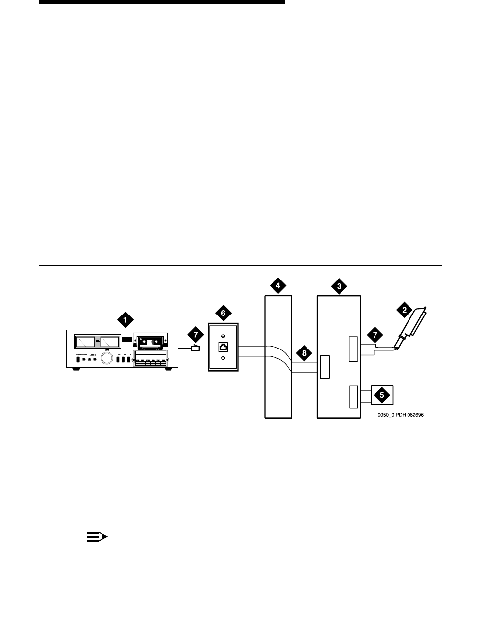
For MCC1, SCC1, CMC1, and G600 Media Gateways
Issue 4 October 2002 193555-233-116
3. Connect a cable from the assigned port carrier slot to J1 on the 909A/B
universal coupler (see Chapter 1, ‘‘909A/B universal coupler’’). A wiring
block must be locally engineered.
a. Connect the T-lead at pin 5 and the R-lead at pin 4 of J1 on the
909A/B universal coupler to the corresponding leads from the
TN2183.
b. Connect the CT-lead at pin 5 and the CR-lead at pin 4 of J2 on the
909A/B universal coupler to the MDF.
4. Install patch cord/jumper wires at the MDF to connect tip and ring to the
information outlet at the music source.
5. Set the Protection/Paging switch to C1.
6. Connect a modular cord from the information outlet to the music source.
7. Connect -48V to pin 5 and -48V RET to pin 2 of J3 on the 909A/B. The
power source may be an 1151A, 1151A2, or other approved power supply.
8. Administer the switch for the new equipment.
Figure 46. Typical nonregistered equipment connections (auxiliary access) for an MCC1,
SCC1, CMC1, or G600 Media Gateway
NOTE:
A wiring block must be locally engineered.
1. Customer-supplied music source
2. A25D 25-pair cable to auxiliary trunk circuit
pack
3. 909A/B universal coupler
4. Part of main distribution frame
5. Power supply for universal coupler
6. 103A or modular wall jack
7. 4-pair modular cord
8. Tip and ring wires
J2
J3
J1
5
2
4
5
4
5
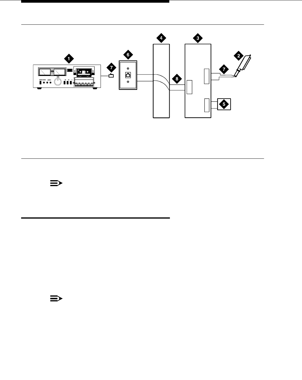
Music-on-hold
555-233-116
194 Issue 4 October 2002
Figure 47. Connections to nonregistered music-on-hold using analog line for an MCC1,
SCC1, CMC1, or G600 Media Gateway
NOTE:
A wiring block must be locally engineered.
For G700 Media Gateways
On a G700 Media Gateway, the music-on-hold feature is connected through a port
on an MM711 Analog Media Module.
The G700 Media Gateway does not support an auxiliary trunk circuit pack.
Therefore, for internal communications controller (ICC) G700 Media Gateway
users, the music-on-hold feature through an auxiliary trunk is not supported.
However, external communications controller (ECC) G700 Media Gateway users
can access the music-on-hold feature if their equipment is physically connected to
a TN763 auxiliary trunk circuit pack in an EPN carrier of an ECC system.
NOTE:
ICC refers to MultiVantage Software running on an S8300 Media Server
installed in, and acting as the primary controller for, a G700 Media Gateway.
ECC refers to MultiVantage Software running on an external S8700 Media
Server within a G700 Media Gateway environment.
1. Customer-supplied music source
2. 25-pair cable to analog line circuit pack
3. 909A/B universal coupler
4. Part of main distribution frame
5. Power supply for universal coupler
6. 103A or modular wall jack
7. 4-pair modular cord
8. Tip and ring wires
0051_0 PDH 062696
J2
J3
J1
5
2
4
5
4
5
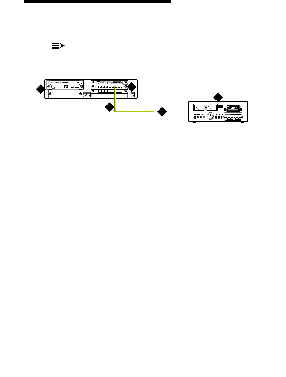
For G700 Media Gateways
Issue 4 October 2002 195555-233-116
Figure 48 shows the connections for the music-on-hold feature on a G700 Media
Gateway.
NOTE:
If you want multiple music sources, you must use multiple ports on the
MM711 Analog Media Module.
Figure 48. Typical music-on-hold equipment connections for a G700 Media Gateway
To hook up music-on-hold from a G700 Media Gateway:
1. Connect one end of an RJ-45 cable to a port in the MM711 Analog Media
Module.
2. Connect the other end of the RJ-45 cable to a KS-23395-L3 coupler.
3. Connect the KS-23395-L3 coupler to the customer-supplied music source.
Follow the manufacturer’s instructions to properly connect the music
source to the KS-23395-L3 coupler.
4. Administer the switch for the new equipment.
1. G700 Media Gateway
2. MM711 Analog Media Module
3. RJ-45 connection
4. KS-23395-L3 coupler
5. Music source
cydfholdKLC 091802
ALM
TST
ACT
123456 87
ALM
TST
ACT
123456 87
REMOVE
ALM
TST
ACT
OKTO SHUT DOWN
SERVICES USB 1 USB 2
E1/T1 EIA 530A DCE
ALM
TST
ACT
SIG
EISO EMSM EOSI
12
4
5
3

Music-on-hold
555-233-116
196 Issue 4 October 2002

Issue 4 October 2002 197555-233-116
17
Paging and announcement
equipment
This chapter explains the most common system configurations for the paging
feature of the MultiVantage Software. This chapter provides information on the
following features:
■‘‘Loudspeaker paging for MCC1, SCC1, CMC1, or G600 Media Gateways’’
■‘‘ESPA radio paging’’
■‘‘External ringing’’
■‘‘Queue warning indicator’’
■‘‘Loudspeaker paging for G700 Media Gateways’’
Background information
The following background information outlines four configurations that are related
to setting up paging and announcement equipment. The four configurations are:
■‘‘IP configurations’’
■‘‘Configuration using the S8700 Media Server in a multi-connect
configuration controlling a G700 Media Gateway’’
■‘‘S8700 Media Server in a multi-connect configuration networked with a
S8300 Media Server in a G700 Media Gateway and a DEFINITY CSI’’
■‘‘Configuration using the S8700 Media Server with IP connect’’

Paging and announcement equipment
555-233-116
198 Issue 4 October 2002
IP configurations
IP is implemented using the TN2302AP, which is an IP Media Processor circuit
pack inside the Media Server/Media Gateway. The TN2302AP IP Media
Processor provides H.323 trunk connections and H.323 voice processing for IP
phones. The features that use the TN2302AP also require the TN799 C-LAN
circuit pack.
H.323 IP trunk (IP solutions mode)
The IP Media Processor circuit pack (either the TN2302AP or the TN802B)
supports the H.323 version 2 protocol, and operates with H.323 version 2
endpoints, including stations, trunks, and gateways. An IP Media Processor circuit
pack enables H.323 trunk service using IP connectivity between two Avaya
MultiVantage Software systems.
H.323 trunk groups can be configured as:
■MultiVantage Software-specific tie trunks supporting ISDN trunk features,
such as DCS+ and QSIG
■Generic tie trunks permitting interconnection with other vendors’ H.323 v2-
compliant switches
■Direct-inward-dial (DID) type of “public” trunks providing access to the
switch for unregistered users
The TN2302AP requires the TN799 for signaling. The TN2302AP IP Media
Processor is also used for H.323 VoIP applications.
Configuration using the S8700 Media Server in a
multi-connect configuration controlling a G700
Media Gateway
NOTE:
The Avaya™ S8700 Media Server with an MCC1 or SCC1 Media Gateway
is called a “multi-connect” configuration.
The S8300 Media Server in a Local Survivable Processor (LSP) configuration
(shown in Figure 49) is located in the G700 Media Gateway. In the event of a loss
in communication between the S8700 and the G700, the LSP provides call
processing for the endpoints that register with it.
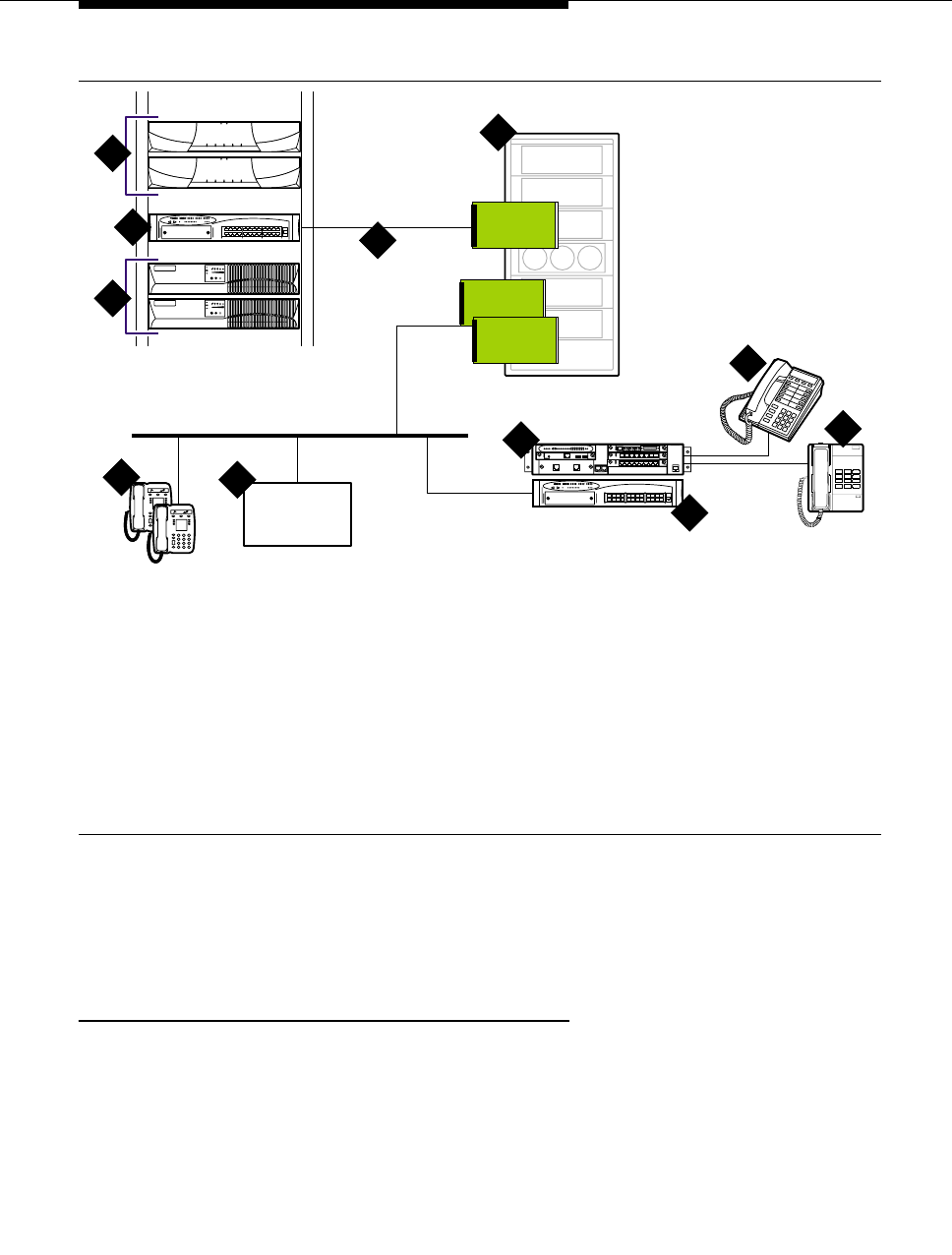
Background information
Issue 4 October 2002 199555-233-116
Figure 49. S8700 Media Server in a multi-connect configuration controlling a G700
Media Gateway
S8700 Media Server in a multi-connect
configuration networked
with a S8300 Media Server in a G700 Media
Gateway and a DEFINITY CSI
For the S8700 Media Server in a multi-connect configuration, networked with a
S8300 Media Server in a G700 Media Gateway, and a DEFINITY CSI (shown in
Figure 50) — known as the “multi-site” configuration — the paging feature has to
be administered locally in each system and cannot be administered across
systems.
1. S8700 Media Servers in a multi-
connect configuration
2. Ethernet switch
3. Uninterrupted Power Supply (UPS)
units, one for each server
4. MCCI Media Gateway (containing
the paging circuit packs)
5. Dedicated LAN connectivity to the
IPSI board in the MCCI Media
Gateway
6. IP phones connected to or running
off of the customer’s LAN
7. INTUITY Audix connected through
an IP
8. G700 Media Gateway, with LSP
S8300 Media Server
9. Multi-function digital phones
10. Analog phones
11. Ethernet switch
LAN
CLAN
A
IPSI
IP Media
Processor
1
11
3
A
Voice Mail
cydcrbro KLC 080202
V1
4
5
6
8
9
10
7
2

Paging and announcement equipment
555-233-116
200 Issue 4 October 2002
Figure 50. Multi-site environment
In Figure 50, an S8700 Media Server in a multi-connect configuration (top middle)
is networked with an S8300 Media Server in a G700 Media Gateway (bottom left)
and a DEFINITY CSI (bottom right).
In this multi-site environment, there are a number of standalone solutions
networked together using protocols such as QSIG or DCS. Each location has its
own processing capability and separate managed configurations. These
configurations can be a mix of different solutions. This configuration can also
support video, modem, and other non-audio functionalities.
Configuration using the S8700 Media Server with
IP connect
NOTE:
The S8700 Media Server with a G600 Media Gateway is called an
“IP connect” configuration.
LAN LAN
LANLAN
cydcmse LJK 032402
PSTN PSTN
WAN
V1
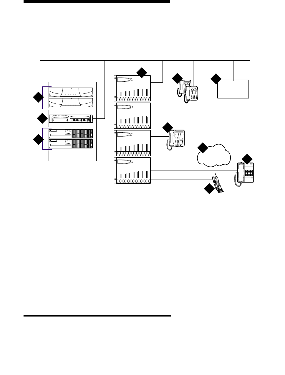
Loudspeaker paging for MCC1, SCC1, CMC1, or G600
Media Gateways
Issue 4 October 2002 201555-233-116
This configuration (Figure 51) has all IP trunks. At this time, IP trunks support
audio-only functionalities. Therefore, this configuration supports audio-only
functionalities over these IP trunks.
Figure 51. S8700 Media Server with IP connect
The G600 Media Gateway, connected to the S8700 Media Server by IP, is the
only supported connectivity in the IP connect configuration. The G600 contains
10 slots and can use traditional DEFINITY circuit packs.
Loudspeaker paging for MCC1, SCC1,
CMC1, or G600 Media Gateways
In an MCC1, SCC1, CMC1, or G600 Media Gateway, the loudspeaker paging
feature provides a connection from a TN763B/C/D auxiliary trunk circuit pack (or
equivalent) to a customer-supplied paging amplifier.
1. S8700 Media Servers
2. Ethernet switch
3. Uninterrupted Power Supply (UPS)
units
4. G600 Media Gateway
5. DCP phones
6. IP phones
7. Analog phones
8. T1/E1 connectivity
9. Wireless phones
10. INTUITY Audix connected through
an IP
LAN
PSTN
1
2
3
INTUITY
Voice Mail
cydcg600 LJK 032402
T1/E1
46
7
8
9
10
5

Paging and announcement equipment
555-233-116
202 Issue 4 October 2002
Loudspeaker paging without paging adapter
Figure 52 shows the connections for the loudspeaker paging feature. These
connections are used when the loudspeaker interface equipment is not located in
the equipment room. If the equipment is located in the equipment room, the
information outlet is not required. The connections shown are for one zone.
Figure 52 also shows connections from an optional customer-supplied music
source to the loudspeaker system through a paging amplifier, as well as
connections to the loudspeaker system through a 909A/B universal coupler (see
Chapter 1, ‘‘909A/B universal coupler’’).
NOTE:
If the loudspeaker paging system provides a talkback microphone at the
speakers, the microphone must be FCC approved (or equivalent), or a
909A/B universal coupler is required.
Figure 52. Connections for loudspeaker paging without paging adapter for an MCC1,
SCC1, CMC1, or G600 Media Gateway
NOTE:
On the 25-pair cable to TN763B/C/D auxiliary trunk circuit pack, SZ1
connects to GRD on key 10. The 50 points amphenol is connected to the
back of a G600 Media Gateway.
1. 25-pair cable to TN763B/C/D
auxiliary trunk circuit pack
2. Loudspeaker paging system
3. 909A/B universal coupler (if
required)
4. Part of main distribution frame
(MDF) circuits 1-16
5. Paging amplifier
6. Music source for background
music over loudspeakers
(optional)
7. 103A or modular wall jack
8. To SZ1 on TN763 connector
9. Tip and ring wires
10. -48 VDC power supply for 909B
cydfnzm KLC 091202
J2
J3
J1
5
1
2
2
7
4
4
52
3
6
51
23
4
5
7
8
9
9
10
6

Loudspeaker paging for MCC1, SCC1, CMC1, or G600
Media Gateways
Issue 4 October 2002 203555-233-116
Loudspeaker paging access without universal
coupler
1. Determine port assignment of paging zone(s) from loudspeaker paging
form.
2. At the main distribution frame, locate the connecting block and terminals
assigned to the selected port.
3. On the locally engineered wiring block, place a strap between terminals S
and SZ. Place a strap between terminals S1 and SZ1.
4. Install patch cord/jumper wires at the main distribution frame.
5. Connect a 2-pair line cord (modular plug at one end) from the information
outlet to the paging amplifier (to the loudspeaker system).
6. Install loudspeaker equipment according to the manufacturer’s instructions.
7. Administer the switch for the new equipment.
Loudspeaker paging with universal coupler
An information outlet provides access to loudspeaker paging. The system side of
the main distribution frame connects to a 909A/B universal coupler. Make
provisions for the DC power that the 909A/B universal coupler requires, such as a
1151A, 1151A2, or other approved -48VDC power supply.
Six leads (T, R, SZ, SZ1, S, and S1) connect the adapter to an auxiliary trunk
circuit pack located in a port carrier.
1. Determine port assignment of paging zone(s) from loudspeaker Paging
form.
2. Identify carrier slot and label both ends of an A25D (male to male) cable.
3. Connect a cable from the 909A/B to the system side of the main
distribution frame. A wiring block must be locally engineered.
4. Chapter 1, ‘‘909A/B universal coupler’’ provides details of the connections
between the 909A/B universal coupler and the wiring blocks.
!CAUTION:
Damage to the 909A/B may occur if the cable is plugged into J3
before all cross-connects are completed.
5. On the 909A/B universal coupler:
■Connect seizure control voltage of from -9 to -70 volts to the PG2/
BZ2 connection (pin 2 of J1). Switching voltage to the PG2/BZ2
connection can be from the 909’s -48-volt supply.
■Connect a -48 VDC power source to the -48 and GRD terminals on
the 909A/B.
6. Install patch cord/jumper wires at the main distribution frame.
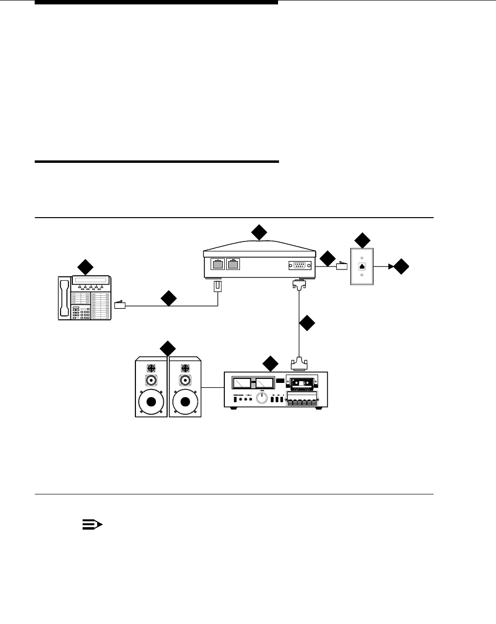
Paging and announcement equipment
555-233-116
204 Issue 4 October 2002
7. Connect a 2-pair line cord (modular plug at one end) from the information
outlet to the loudspeaker system.
8. Install loudspeaker equipment according to the manufacturer’s instructions.
9. Connect an approved -48 VDC power source to the -48 and GRD terminals
(pins 5 and 2, respectively, of J3).
10. Administer the switch for the new equipment.
ESPA radio paging
Figure 53 shows typical connections to European Standard Paging Access
(ESPA) equipment. Connect the LINE jack on the PassageWay interface to a
digital line 4-wire DCP circuit pack through the MDF.
Figure 53. Typical ESPA radio paging connections
NOTE:
The G700 Media Gateway does not support an auxiliary trunk media
module. Therefore, the loudspeaker paging feature through an auxiliary
trunk is not supported on a G700 Media Gateway.
ECC G700 Media Gateway users can access this equipment if equipment is
physically connected to a TN763 auxiliary trunk circuit pack in an EPN
carrier of an ECC system.
1. DCP telephone
2. 4-pair modular cord
3. PassageWay interface
4. 4-pair modular cord
5. 103A or modular wall jack
6. To digital line circuit pack
7. RS-232 connector
8. ESPA radio paging equipment
9. Loudspeaker paging system
cydf004 RPY 12309
7
PHONE LINE
POWER
1
2
3
4
5
6
7
8
9

External ringing
Issue 4 October 2002 205555-233-116
External ringing
Connections for external ringing are at an information outlet. The system side of
the main distribution frame (MDF) is connected to a TN2183 (or equivalent)
analog line circuit pack in an MCC1, SCC1, CMC1, or G600 Media Gateway.
NOTE:
Up to three devices can be connected to one analog line circuit pack port.
This does not apply to the G700 Media Gateway.
1. Wire the ringing device to the information outlet.
2. Administer the switch for the new equipment.
Queue warning indicator
The connections for the queue warning indicator are the same as external ringing.
An AC indicator (light) such as a 21C49 can be used in a Uniform Call
Distribution/Direct Departmental Calling (UCD/DDC) queue. The light is
connected to an information outlet. The system side of the MDF is connected to
an analog line circuit pack located in a port carrier.
NOTE:
This does not apply to the G700 Media Gateway.
1. Wire the queue warning indicator to the information outlet.
2. Administer the switch for the new equipment.
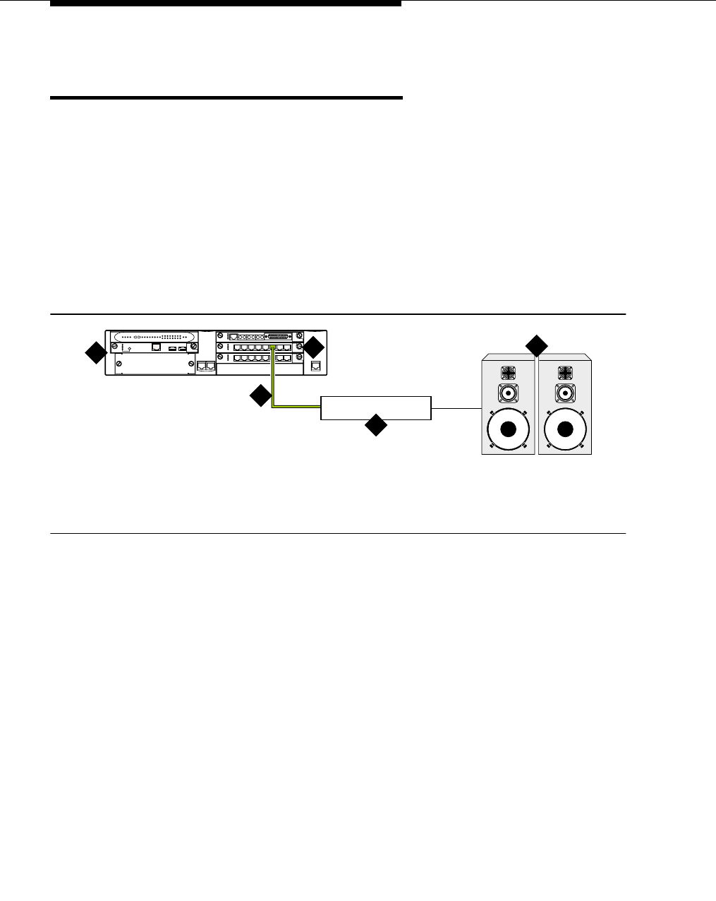
Paging and announcement equipment
555-233-116
206 Issue 4 October 2002
Loudspeaker paging for G700 Media
Gateways
On a G700 Media Gateway, the loudspeaker paging feature is connected through
a port on an MM711 Analog Media Module.
The G700 Media Gateway does not support an auxiliary trunk circuit pack.
Therefore, the loudspeaker feature through an auxiliary trunk is not supported on
a G700 Media Gateway. However, ECC G700 Media Gateway users can access
the loudspeaker paging feature if equipment is physically connected to a TN763
auxiliary trunk circuit pack in an EPN carrier of an ECC system.
Figure 54 shows the connections for loudspeaker paging, dial dictation, or
recorded announcement features on a G700 Media Gateway.
Figure 54. Typical loudspeaker equipment connections for a G700 Media Gateway
To hook up loudspeaker paging from a G700 Media Gateway:
1. Connect one end of an RJ-45 cable to a port in the MM711 Analog Media
Module.
2. Connect the other end of the RJ-45 cable to a customer-supplied
telephone hybrid device.
3. Follow the manufacturer’s instructions to properly connect the telephone
hybrid device to your loudspeaker paging system.
4. Administer the switch for the new equipment.
1. G700 Media Gateway
2. MM711 Analog Media Module
3. RJ-45 connection
4. Telephone hybrid (third party) device
5. Loudspeaker paging system
cydfspkKLC 091802
ALM
TST
ACT
123456 87
ALM
TST
ACT
123456 87
REMOVE
ALM
TST
ACT
OKTO SHUT DOWN
SERVICES USB 1 USB 2
E1/T1 EIA 530A DCE
ALM
TST
ACT
SIG
EISO EMSM EOSI
12
4
3
5

Issue 4 October 2002 207555-233-116
18
Multimedia communications
products: MMCX, MMCH, ESM
This chapter provides information on connecting the following equipment to:
■MASI for MMCX
■Wideband endpoints
■Multimedia call handling (MMCH)
NOTE:
The information in this chapter does not apply to the G700 Media Gateway
configurations.
MASI for MMCX
The multimedia application server interface (MASI) enables the DEFINITY ECS to
provide calling features to the MultiMedia Communications eXchange (MMCX).
The MMCX server connects to the Avaya Media Server through a D8W cable.
See Table 24 for pin assignments and Figure 55 for pin locations.
Table 24. D8W cable modular pin assignments
Pin Signal Pin Signal
1 Receive ring 5 Transmit Tip
2 Receive tip 7 No connection
3 No connection 7 No connection
4 Transmit ring 8 No connection
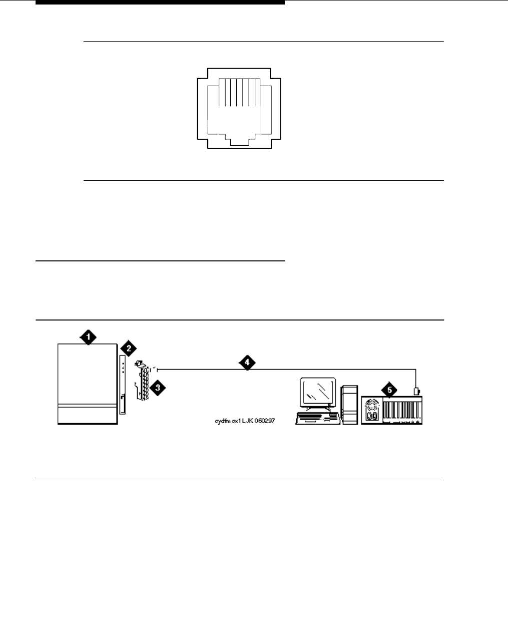
Multimedia communications products: MMCX, MMCH,
ESM
555-233-116
208 Issue 4 October 2002
Figure 55. Modular jack pin assignment
You can connect the MMCX server to the Avaya Media Server by either of two
methods: directly or through the main distribution frame.
Direction connection
Figure 56 illustrates the direct method, which connects an Avaya Media Server
DS1 interface circuit pack to a customer-supplied digital line PC board in the
MMCX, through a D8W cable.
Figure 56. MMCX connected directly to an Avaya Media Server
1. Avaya Media Server
2. TN464F DS1 interface circuit pack
3. 357A adapter
4. D8W 4-pair modular cord
5. MMCX server
18
plmxmod PDH 05139
7
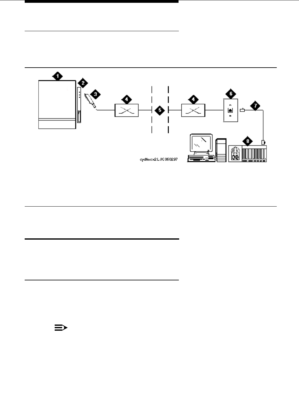
Wideband endpoints
Issue 4 October 2002 209555-233-116
Main distribution frame connection
Figure 57 illustrates the main distribution frame method which connects a Avaya
Media Server DS1 interface circuit pack, with a 25-pair cable to the MDF, to the
customer-supplied digital line PC board in the MMCX, through a D8W cable.
Figure 57. MMCX connected to an Avaya Media Server through the MDF
Wideband endpoints
Wideband endpoints include video equipment or bridges/routers for LANs. Use
the running list that accompanies the system to make cable connections.
Nonsignaling configuration
A nonsignaling connection to a wideband endpoint may connect to a channel
service unit (CSU). If not using a CSU, the distance between the system and the
endpoint is limited to a few hundred feet. See Figure 58. The maximum distance
depends on the type of cable and type of endpoint.
NOTE:
The MM710 media module (for the G700 Media Server) has a built-in
channel service unit (CSU). Therefore, the CSU in Figure 58 and Figure 59,
plus the references in the accompanying text about distance limitations
when working without a CSU, do not apply to a G700 Media Gateway
configuration.
1. Avaya Media Server
2. DS1 interface circuit pack
3. 25-pair cable
4. Main distribution frame (MDF)
5. Public telephone network
6. 103A or modular wall jack
7. D8W 4-pair modular cord
8. MMCX server
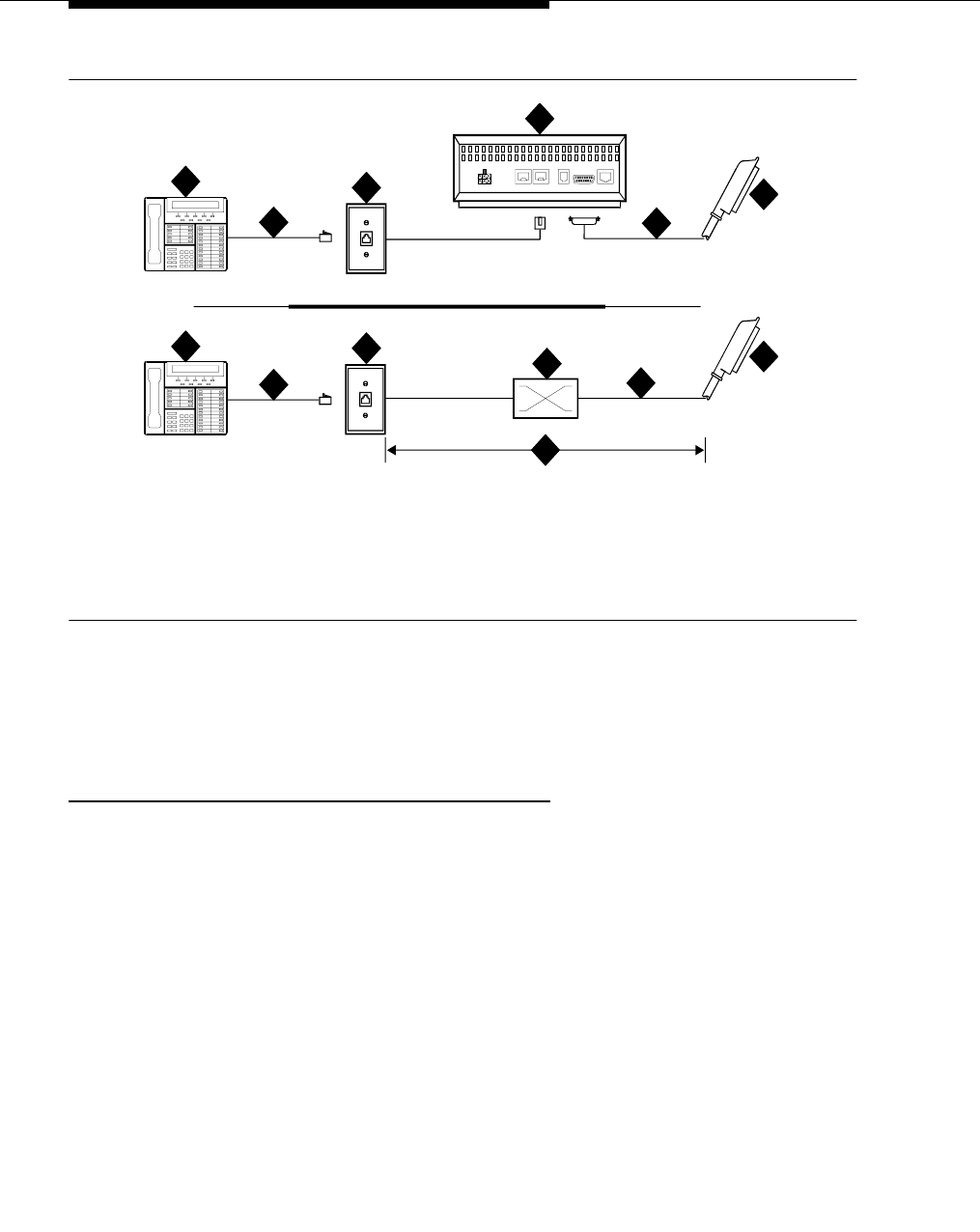
Multimedia communications products: MMCX, MMCH,
ESM
555-233-116
210 Issue 4 October 2002
Figure 58. Typical nonsignaling wideband configuration
If using a CSU, the distance between connections may be up to 1300 ft.
(397.2 m). The maximum distance to the endpoint depends on the type of cable
and the specifications of the endpoint.
Signaling configuration
A signaling connection from the system to a wideband endpoint passes through a
bandwidth controller. The distance between the system and the bandwidth
controller depends on the type of cable and controller. Figure 59 shows
connections with and without a CSU.
1. Wideband endpoint (wire per manufacturer)
2. Modular cord
3. 103A or modular wall jack
4. Channel service unit (CSU)
5. H600-307 cable to DTE connector on CSU
6. DS1/E1 circuit pack
7. Main distribution frame (MDF)
8. Distance limit depends on cable and
endpoint type.
9. A25D 25-pair cable (male-to-male)
cydf049 RPY 123097
AUX POR T COM P ORT MODEM
DTE
NETW ORK
POWER
1
1
2
2
3
3
4
5
6
6
7
8
9
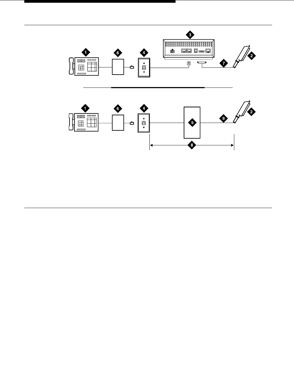
Wideband endpoints
Issue 4 October 2002 211555-233-116
Figure 59. Typical signaling wideband configuration
The bandwidth controller connects directly to the wideband endpoint. The
controller typically installs near the endpoint where they directly connect (usually
within a few feet of each other).
■For non-CSU installations, cross the transmit and receive lines so a
transmit signal from the DS1/E1 circuit pack connects to the receive
connection on the bandwidth controller and a transmit signal from the
bandwidth controller connects to the receive connection on the DS1/E1
circuit pack.
■For CSU installations, cross the transmit and receive lines between the
CSU and the bandwidth controller.
Figure 60 shows a remote port module. In this configuration, there can be
considerable distance between the bandwidth controller and the wideband
endpoint. The maximum distance between elements depends on the quality of the
cables and on the specifications of the wideband equipment.
1. Wideband endpoint (wire per
manufacturer)
2. To DS1/E1 circuit pack
3. Optional channel service unit (CSU)
4. 103A or modular wall jack
5. Part of main distribution frame
6. Bandwidth controller
7. H600-307 cable to DTE connector on CSU
8. Distance limit depends on cable type and
bandwidth controller type
9. A25D 25-pair cable (male-to-male)
AUX PORT COM PORT MODEM
DTE
NETWORK
POWER
c
y
df047 PDH 091396
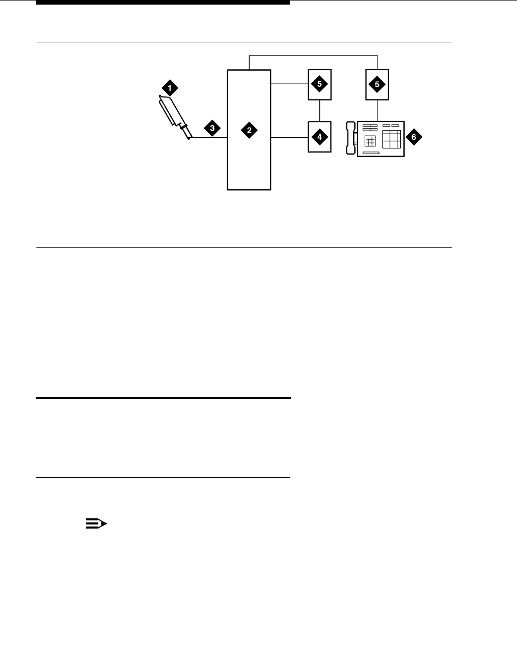
Multimedia communications products: MMCX, MMCH,
ESM
555-233-116
212 Issue 4 October 2002
Figure 60. Typical signaling wideband configuration with remote port module
1. For non-CSU installations, cross the transmit and receive lines so a
transmit signal from the TN464F connects to the receive connection on the
bandwidth controller and a transmit signal from the bandwidth controller
connects to the receive connection on the TN464F.
2. For CSU installations, cross the transmit and receive lines between the
CSU and the bandwidth controller.
Multimedia call handling (MMCH)
MMCH provides a single point to point conference call using voice, video, and
data from one endpoint to another. The customer must have endpoints and a
personal computer with H.320 desktop video installed.
Connect the endpoints
Use the following procedure and Figure 61 to connect the endpoints:
NOTE:
For a G700 Media Gateway configuration, the DCP telephones that are
supported — item 1 in Figure 61 — are only 2 wire.
1. To TN464F DS1/E1 circuit pack
2. Part of main distribution frame (MDF)
3. H600-307 cable
4. Bandwidth controller
5. Remote port module
6. Wideband endpoint (wire per manufacturer)
c
y
df048 PDH 091396

Multimedia call handling (MMCH)
Issue 4 October 2002 213555-233-116
Figure 61. Typical multimedia call handling connections
NOTE:
The NT1 adapter (item #8) is not used with a MM720 BRI module. The NT1
is a 2/4 converter unit, and the MM720 currently only supports 4-wire
trunking.
In items #7 and #8 above, the connection to both an MM712 DCP media
module and to an MM720 BRI media module is not a 25-pair cable but
rather an RJ45 cable.
1. Each PC MMCH endpoint must contain a BRI adapter.
2. Connect a DCP telephone to a digital line circuit pack. The DCP telephone
must be used in conjunction with the PC. Refer to the tables at the end of
this chapter for the pinout of the digital line circuit pack.
3. Connect the PC BRI adapter to any BRI port on the Avaya Media Server.
Refer to the tables at the end of this chapter for the pinout of an ISDN BRI
circuit pack.
1. DCP telephone, 2 or 4 wire to match type
of circuit pack
2. Personal computer
3. BRI adapter
4. D8W cord
5. 103A or modular wall jack
6. Main distribution frame
7. 25-pair cable to digital line circuit pack
8. 25-pair cable to BRI circuit pack or NT1,
4-to-2 wire adapter
9. Avaya Media Server
10. Multimedia-interface circuit pack
11. Voice conditioner circuit pack

Multimedia communications products: MMCX, MMCH,
ESM
555-233-116
214 Issue 4 October 2002
Administer the system
1. Call INADS and notify the representative that the Multimedia Call
Handling (MMCH)? field on page 2 of the customer-options form must be
changed to y.
2. Logoff the terminal and then log back on the terminal to see your changes.
Administer the endpoints
1. Log in and enter add data-next <or a valid extension number>.
2. The data module form appears. On page 1 of the form, enter the Data
Extension: xxxx, Type: 7500, the Name: user’s name (such as
ProShare), and enter y in Multimedia? field.
3. On page 2 of the form, enter n in the XID? field, and enter n in the MIM
Support? field and press Enter.
Administer one number complex
1. Identify the voice telephone (DCP set) to associate with the data endpoint.
The station record for this voice station must be changed.
2. Type change station station number and press Enter.
3. On screen 1, type the data extension number in the MM Complex Data
Ext: field.
4. On screen 2, type y in the H.320 Conversion? field and press Enter.
5. Type y in the Multimedia Early Answer field and press Enter.
Setup and test the MMCH installation
This section provides general setup and testing procedures for the PictureTel,
ProShare, Vistium, and Zydacron multimedia endpoints. Use the documentation
that accompanies the endpoint equipment for more details.

Multimedia call handling (MMCH)
Issue 4 October 2002 215555-233-116
Configuring the PictureTel
PCS50 (Live 50) and PCS100
These endpoints do not need any special configuration settings. The standard
PictureTel configuration is as follows:
1. Load the LiveShare Plus software first.
2. Enter the user name and company name. Use default values for
subsequent prompts.
3. Enter a site name.
4. Select Restart Windows and FINISH.
5. Load the Live 50 VAFC drivers.
6. Load the Picture Tel Live 50 software.
7. Open the PictureTel Live program group from the Windows™ Program
Manager screen.
8. Double click on the PictureTel Live Configure icon.
9. At the Welcome screen, click on continue.
10. Go to the registration confirmation screen and click on continue.
11. Enter the Network Interface Settings. Be sure that “ISDN” has an “x” in
the box. Click on continue.
12. At the ISDN Parameters screen, set the signaling protocol to USA
Canada: 5ESS Custom Point-to-Point. Click on continue.
13. At the Hardware Settings screen, set the following: Interrupt (IRQ) to 11,
Base I/O Port=280, and Base Memory=D000. Under the Video Input
section, select the NTSC circle. Click on continue.
14. At the Audio Device screen, enter the necessary information.
15. At the Node Name screen, enter a name for the PC using the application
software package.
Table 25. Minimum system requirements
Ve rs io n: Live 50 version 1.7 or higher
Minimum Processor Speed: 487/33 MHz, DX2/77
Disk Space: 20 MB
Memory: 8 MB RAM, 17 MB recommended
ISA Expansion Slots (17-bit): 2 slots
Monitor: VGA, SVGA
Operating System: Windows™ 3.1x or Windows™ 95

Multimedia communications products: MMCX, MMCH,
ESM
555-233-116
216 Issue 4 October 2002
16. At the Modify config.sys screen, click the SAVE button.
17. The remainder of the software loads automatically.
18. When the load is finished, reboot the PC.
19. Open the PictureTel Live program group from the Windows™ Program
Manager screen.
20. Double click on the PictureTel Live icon. The program takes about 1
minute to open.
How to place a PictureTel video call
1. Turn on the video camera. Be sure the green LED is on.
NOTE:
A problem may be encountered when trying to open the PictureTel
application software. If the application seems to freeze during
initialization (no response for several minutes) then there may be a
conflict with the interrupt (IRQ) port setting. Check the PictureTel
configuration to make sure that the IRQ port is set to 11. If
initialization is still a problem, contact a PictureTel representative.
2. Open the PictureTel application program.
3. Two windows should appear: one local video and one remote video.
4. Go to the remote video window (the one without the local video image
inside it).
5. Click on the blue phone icon at the top left of the window.
6. A DIAL PAD window opens. Use the keyboard, or mouse and dial pad, to
enter the DATA extension of another multimedia endpoint. If you are dialing
another PictureTel, you can place a 1B (one 74 Kb channel) call by only
filling in the first telephone extension box on the DIAL PAD window. To
make a 2B (two 74 Kb channels) call, you must put the same called party
extension in the second telephone extension box on the DIAL PAD
window.
7. To initiate a call, click on the VIDEO CALL button on the top right of the
DIAL PAD window.
8. The dial pad disappears and you see a status window that shows “ringing.”
9. When the connection is made, the status window disappears and you can
see the connection status on the bottom bar of the remote video window.
Troubleshooting PictureTel
Symptom: A conference call between a PictureTel and a ProShare has problems
with the video connection or with video switching.
Solution: Be sure the PictureTel is version 1.7 or higher and the ProShare is
version 2.0 or higher.

Multimedia call handling (MMCH)
Issue 4 October 2002 217555-233-116
ProShare configuration
The ProShare system must be set up so that it does not look for a Service Profile
Identifier (SPID) when connecting to the Avaya Media Server. This is important
because you administer the ProShare as a single 7500 data set and the
telephone extension associated with that data set applies to both BRI channels.
1. Load the ProShare software onto the PC using the default values.
2. Enter the company name and serial number of the software.
3. Select the default directory location and install all files.
4. Answer NO to modem Setup.
5. Scroll through the list of countries and select the country in which the PC is
installed.
6. At the Protocol and Switch Mfg window, click on Custom. Click on AT&T
and click on Accept.
7. At the next window, choose PBX for Exchange Switch, and choose G3r (for
Release 8r) or G3i (for Release 8si) (as appropriate) as the PBX type. Click
on Accept.
8. Select yes or no for Phone Call Support.
9. A window with #Phone Numbers and #SPIDS appears. Set #Phone
Numbers to 1 and set #SPIDS to 0.
10. Click on the Aliases button and enter the last 5 digits of the data extension
number and an external alias.
11. Leave the telephone number at default and click on Accept.
12. Select restart windows.
Table 26. Minimum system requirements
Ve rs io n: 2.0 or higher
Minimum Processor Speed: 487/33 MHz, DX2/77
Disk Space: 7 MB
Memory: 12 MB RAM, 17 MB recommended
ISA Expansion Slots (17-bit): 2 slots
Monitor: 740x480, 257-color, VGA, SVGA
Operating System: Windows™ 3.1x or Windows™ 95

Multimedia communications products: MMCX, MMCH,
ESM
555-233-116
218 Issue 4 October 2002
How to place a ProShare video call
1. Boot the ProShare computer.
2. Open the camera lens. Be sure the green LED is on.
3. Open ProShare Personal Conferencing program group from the
Windows™ Program Manager screen.
4. Double click on the ProShare Conferencing icon.
5. If this is a first time install, click on OK for the camera test. This test can
take several minutes to complete.
6. After the tutorial runs (if desired) and the product is registered, the
ProShare application opens with 2 video windows.
7. Click on the Call button. A telephone dial pad appears. Use the dial pad to
enter the telephone number of the desired extension to place a test call to.
The ProShare only makes 2 B calls. The telephone number entered is used
to place both calls. To place a 2B (two 74 kB channels) call to 2 different
telephone extensions, separate them with a colon “:”. To place a 57 kB call
instead of a 74 kB call, enter a pound “#” sign to the end of the called party
extension.
8. To initiate the call, click on the DIAL button on the handset window. The
dialing status displays where the extension was entered. When the
connection is made, remote video appears.
Troubleshooting ProShare
Symptom: Any attempt to place a data call to the complex’s voice station is
denied by the ProShare.
Solution: When configuring the ProShare, you entered the voice extension of the
complex. You need to enter the data extension (Step G, below). To do this:
a. Go to the ProShare directory and run the Diagnostics and Utilities program.
b. Double click on the Hardware and ISDN Configuration utility.
c. Choose ISDN Line Configuration.
d. Set Protocol = custom and Manufacturer = AT&T (5ESS). Click on the
Accept button.
e. Set Switch = PBX, PBX Type = G3r or G3i (for G3si). Click on the Accept
button.
f. Set Phone Call Support = No and click on the Accept button.
g. Set #Phone Numbers = 1, #SPIDs = 0, and Phone Number to the data
endpoint extension. Click on the Accept button.

Multimedia call handling (MMCH)
Issue 4 October 2002 219555-233-116
Symptom: Cannot accept a multimedia telephone call from off-premises to the
single number.
Solution: Under “Aliasing,” enter the data extension number. To do this:
a. Go to the ProShare directory and run the Diagnostics and Utilities program.
b. Double click on the Hardware and ISDN Configuration utility.
c. Choose ISDN Line Configuration.
d. Set Protocol = custom and Manufacturer = AT&T (5ESS). Click on the
Accept button.
e. Set Switch = PBX, PBX Type = G3r or G3i (for G3si). Click on the Accept
button.
f. Set Phone Call Support = No and click on the Accept button.
g. Set #Phone Numbers = 1, #SPIDs = 0, and Phone Number to the data
endpoint extension.
h. Click on the Aliasing button.
i. In the Alias box, enter the data extension number, choose External, click
the Add button, click the OK button, and click the Accept button.
Symptom: Get a short break in audio path during first few seconds of a call. This
is most noticeable when covering to AUDIX/Voice mail.
Solution: ProShare mutes the audio path when it does a “capabilities exchange”
in H.320. This problem is being addressed in later versions of the ProShare
software. Contact your Avaya representative for more information.
Vistium configuration
Table 27. Minimum system requirements
Ve rs io n: 1.03.10 or higher
Minimum Processor Speed: 487/33 MHz, DX2/77
Disk Space: 10 MB
Memory: 8 MB RAM, 17 MB recommended
ISA Expansion Slots (17-bit): 1 slot
Monitor: VGA, SVGA
Operating System: Windows™ 3.1x or Windows™ 95

Multimedia communications products: MMCX, MMCH,
ESM
555-233-116
220 Issue 4 October 2002
Zydacron configuration
These endpoints do not need any special configuration settings. The standard
configuration for a Avaya Media Server is as follows. Use the documentation that
accompanies the Zydacron equipment for more details.
1. Open Windows and load the software application.
2. Select Full Installation.
3. Click on OK for the default location of the application directory
(c:\ZYDAPP2).
4. Select Yes to reset the video drivers (if desired).
5. View or close the READZA2.txt file as desired.
6. When the Collaboration Software dialog box opens, select Yes if another
vendor’s video conferencing application is being loaded. Select No if only
Zydacron software is being loaded.
7. The software continues to load automatically. When finished, the
application icons appear in the program group.
How to place a Zydacron video call
1. Turn on the video camera. Be sure the green LED is on.
2. Double click on the Zydacron icon to start the program. The program may
take about 30 seconds to open.
3. Two local video windows should appear.
4. Click the Dial icon from the Main toolbar.
5. Use the keypad or the computer keyboard to enter the telephone number
of the test endpoint or telephone.
6. To initiate the call, click on the CALL button. The Incoming Call screen
appears on the test endpoint (or the test telephone rings).
Table 28. Minimum system requirements
Ve rs io n: Z250 v. 1.0 or ZydApp2 v. 1.3
Minimum Processor Speed: 487/33 MHz, DX2/77
Disk Space: 5 MB
Memory: 4 MB RAM, 8 MB recommended
ISA Expansion Slots (17-bit): 1 slot
Monitor: VGA, SVGA
Operating System: Windows™ 3.1x or Windows™ 95

Multimedia call handling (MMCH)
Issue 4 October 2002 221555-233-116
7. Select ANSWER on the test endpoint or pick up the test telephone
handset.
8. Remote video appears on the local screen and a talk path is opened on the
headset. For a test telephone, a talk path is opened.
Troubleshooting Zydacron
Symptom: After each PC reboot, the first time you bring up the Zydacron
application and receive a telephone call, if you do not answer the data call, the
answer screen stays frozen in the window.
Solution: Restart the Zydacron application. Press the Ctrl, Alt, and Del keys at the
same time. This brings up a window that allows you to select a task. Select the
Zydacron application and click on the end task button.
Symptom: Cannot make an outgoing call. Get a Message Interrupt.
Solution: The interrupt (IRQ) setting is incorrect. Contact your Zydacron
representative for the recommended IRQ settings.
Place conversion test call
NOTE:
The H.320 Conversion?: field must be set to y on page 2 of the Station
Form.
Place a conversion test call to an endpoint with a known video capability (for
example: call your voice station from your PC).
Expansion services module
The Expansion Services Module (ESM) provides T.120 data sharing capability on
a MMCH multipoint H.320 video conference. Each person in the conference must
have endpoints and a personal computer with the H.320 video application
installed. The Avaya Media Server must have the expansion service module
installed.
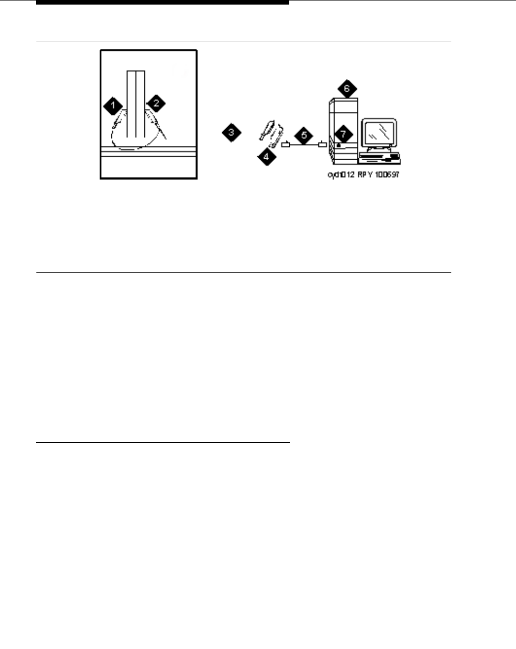
Multimedia communications products: MMCX, MMCH,
ESM
555-233-116
222 Issue 4 October 2002
Figure 62. Typical multimedia call handling ESM connections
ESM installation
Use the following procedure and Figure 62 to connect to the ESM equipment:
1. Install the TN2207 primary rate interface (PRI) circuit pack and the
TN787F/G/H/J/K multimedia interface (MMI) circuit pack in the port carrier.
2. Record the circuit pack locations.
3. Connect the ESM Y-cable as shown.
Administration
1. Enter list configuration all, and a list of the installed carriers, circuit
packs, and ports appears.
2. Record the location (board number) of the new circuit packs and verify that
all other required circuit packs (refer to ‘‘ESM installation’’) are present.
3. Enter add DS1 xxxxx, (where xxxxx is the location of the TN2207 PRI
circuit pack recorded in step 2), and the DS1 circuit pack administration
form appears.
4. Set the Name: field to ESM DS1
5. Set the Bit Rate: field to 2.048
6. Set the Line Coding: field to hdb3
7. Set the Signaling Mode: field to isdn-pri
8. Set the Connect: field to pbx
1. Port B Y-cable connector to a TN787
multimedia interface (MMI) circuit pack
2. Port A Y-cable connector to a TN2207 PRI
circuit pack
3. 25-pair Y-cable
4. 357A adapter
5. D8W cord connected to 357A adapter
S/B port 8
6. Expansion service module (ESM)
7. Port B on compatible primary rate
interface (PRI) card

Multimedia call handling (MMCH)
Issue 4 October 2002 223555-233-116
9. Set the Interface: field to network
10. Set the Country Protocol:field to 1
11. Set the Protocol Version:field to a
12. Set the CRC?:field to y
13. The Idle Code default is 11111111.
14. The DCP/Analog Bearer Capability default is 3.1 kHz.
15. Set the MMI Cabling Board: field to xxxxx (where xxxxx is the
location of the TN787F/H/J/K MMI circuit pack recorded in step 2). This
must be the slot for port B of the Y-cable.
16. The MMI Interface: field ESM appears.
17. Enter add signaling-group next and the signaling-group form appears.
18. Change Associated Signaling: field to y.
19. Change Primary D-Channel Port: field to xxxx17 (where xxxx is the
address of the TN2207 PRI circuit pack, for example: 1B0517).
20. The Max Number of NCA TSC: default is 0.
21. The Max Number of GA TSC: default is 0.
22. Trunk Group for NCA TSC: ____ (leave blank)
23. Trunk Group for Channel Selection:____ (leave blank)
24. Logoff the terminal and then log back on the terminal to view your changes.
Place test call
Place multimedia data-conference call to an endpoint with known video capability
to test the esm function.
Troubleshooting
To determine ESM link status enter the following commands from the system
administration terminal:
1. Status esm
2. Status signaling-group
3. List MMI
NOTE:
When you move ESM circuit packs, you MUST remove the DS1 and
signaling group translations. You cannot use the change circuit pack
command.
Refer to ‘‘Setup and test the MMCH installation’’ on page 214 for further
information.

Multimedia communications products: MMCX, MMCH,
ESM
555-233-116
224 Issue 4 October 2002

Issue 4 October 2002 225555-233-116
19
Property management system (PMS)
This chapter provides information on connecting the property management
system (PMS) and a terminal, journal printer, or both.
NOTE:
The information in this chapter does not apply to the G700 Media Gateway
configurations.
Connecting the property management
system (PMS)
A data module and an asynchronous data unit form the interface between the
DEFINITY and the property management system (PMS). See Figure 63 and
Chapter 4, ‘‘Data modules and asynchronous data units’’, for connection and
configuration information.
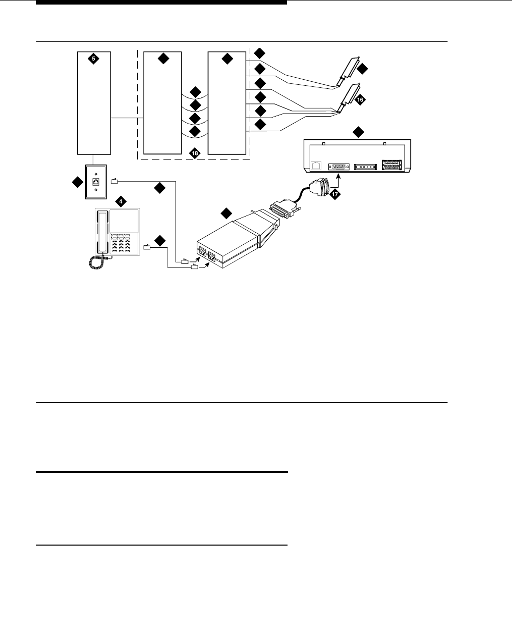
Property management system (PMS)
555-233-116
226 Issue 4 October 2002
Figure 63. Connections to an asynchronous data unit
Connecting a terminal and/or journal
printer
You can connect customer data terminals, host computers, and/or an optional
journal printer in either of two ways.
Using data modules
1. Configure printer or terminal in accordance with the recommendations in
the vendor’s documentation.
2. Configure the data module for the printer or terminal, using the instructions
in Chapter 4, ‘‘Data modules and asynchronous data units’’.
3. Identify the port associated with the data unit or data module using the
Data Module Form (see ‘‘Administer the data modules’’ on page 95).
1. Z3A1 or Z3A2 ADU
2. 4-pair line cord
3. 103A or modular wall jack
4. Analog telephone
5. Satellite site or adapter location
6. Station side blue or white field
7. System side
8. Data module
9. TXT
10. TXR
11. PXT
12. PXR
13. Tip
14. Ring
15. To analog line circuit pack
16. To data line circuit pack
17. 25-pin RS-232-D connector (male)
18. Main distribution frame
2
2
3
910
10 11
11 12
12
6
8
14 15
LINE V. 3 5
POWER
RS-366/RS-232
9
13
7
0002
_
1 RBP 062596
1

Connecting PMS and printers using TCP/IP
Issue 4 October 2002 227555-233-116
4. Establish a physical connection from the data port on the circuit pack,
through the MDF, to the wall jack where the data unit is installed.
5. Connect the data modules to the equipment.
Using an asynchronous data unit (ADU)
and a data line circuit pack
You connect an asynchronous data terminal through an ADU to a data line circuit
pack. Normally, the connected data terminal powers the data unit. The data unit
can also be remotely or locally powered using a 2012D transformer with a 248B
adapter. Data units connected to receive-only printers require external power.
1. Configure printer or terminal in accordance with the recommendations in
the vendor’s documentation.
2. Identify the port associated with the data unit or data module using the
Data Module Form (see ‘‘Administer the data modules’’ on page 95).
3. Establish a physical connection from the data port on the circuit pack,
through the MDF, to the wall jack where the data unit is installed.
4. Connect the information outlet to the ADU.
5. Connect the RS-232 plug on the ADU or data module to the data terminal.
6. Connect the printer to the ADU using a modem or data module, following
the instructions in Chapter 4, ‘‘Data modules and asynchronous data
units’’, and Chapter 5, ‘‘External modems’’.
Connecting PMS and printers using
TCP/IP
Property management systems (PMS) and printers can be connected to the
switch using asynchronous TCP/IP links. This section provides information on
connecting these adjuncts to the C-LAN and performing the initial administration.
Task list
Whether you use an end-to-end TCP/IP configuration, a terminal server or a PC
running RSP, you must complete the following tasks:
■‘‘Administering IP node names’’ on page 131.
■‘‘Administering IP services’’ on page 132.
■‘‘Administering adjunct parameters’’ on page 228.
■If you are using a terminal server, also complete ‘‘Installing and
administering the terminal server’’ on page 122.
■If you are using a PC with the Downloadable RSP Tool, complete ‘‘Using
the downloadable reliable session-layer protocol tool’’ on page 229.

Property management system (PMS)
555-233-116
228 Issue 4 October 2002
Administering adjunct parameters
You must administer adjunct parameters to let the system know that the adjunct is
connected through TCP/IP.
PMS, PMS journal, and PMS log printers
1. Type change system-parameters hospitality and press RETURN.
The Hospitality screen appears.
2. On this screen, you can administer the PMS Log Endpoint (PMS_LOG),
the PMS Journal Endpoint (PMS_JOURNAL), the PMS Endpoint (PMS),
for whichever of these is connected through TCP/IP.
3. In the PMS Log Endpoint field, type CDR1. If you use a secondary output
device, and that device is also connected through TCP/IP, type CDR2 in
the Secondary Output Endpoint field.
4. Press ENTER to save your changes.
System printer
1. Type change system-parameters features and press RETURN.
The Feature-Related System Parameters screen appears.
2. Move to Page 4.
3. In the System Printer Endpoint field, type SYS_PRNT.
4. Press ENTER to save your changes.
Testing the switch-to-adjunct link
You can use the test, status, busyout and release commands for to find and
correct problems with system printer, PMS log, PMS journal and PMS links. For
more information about these commands, see the Maintenance manual for your
switch.
If a link does not come up immediately, try using the busyout (pms-link, journal-
link pms-log and wakeup-log) and release (pms-link, journal-link pms-log and
wakeup-log) commands.

Connecting PMS and printers using TCP/IP
Issue 4 October 2002 229555-233-116
Using the downloadable reliable session-layer
protocol tool
The intent of the Reliable Session-Layer Protocol (RSP) is to guarantee delivery
of data records from the switch to an output device that connects to the switch
over an asynchronous TCP/IP link. The Downloadable RSP tool allows you to
implement this protocol on a PC that collects data records in a file. The protocol
assures that the data records arrive safely at the PC. You can then send the
output file to a printer.
Setting up an RSP configuration
To set up an RSP configuration:
■Administer the PC as a client application on the switch.
■Download, install, and administer the RSP for the PC
Setting up the switch
To set up the server application on the switch:
■‘‘Administering IP node names’’ on page 131
Give the PC a node name. The IP address is the IP address of the PC that
is running the RSP tool.
■‘‘Administering IP services’’ on page 132
The service type = SYS_PRNT, the Remote Node = the node name
assigned to the PC. Remote port is the port assigned as the listen port on
the PC. You can figure out what this is by starting the RSP Server
application, clicking on Start, and checking in the output window to see
what port the server is listening on.
Setting up the PC
To set up the client application on the PC you will be:
■‘‘Downloading RSP’’
■‘‘Installing RSP’’
■‘‘Administering RSP’’

Property management system (PMS)
555-233-116
230 Issue 4 October 2002
Downloading RSP
The RSP is available from the Avaya support web site as a self-extracting
executable. To download the RSP:
1. Browse to the Avaya Customer Support web site:
http://support.avaya.com/sd.jhtml
2. Select the RSP tool from the web site.
3. When queried, save the setup.exe file to a temporary folder on your
computer. It is approximately 1.4-MB.
Installing RSP
To install the RSP:
1. Double-click the setup.exe file.
The Install Shield Wizard steps you through the installation.
2. When prompted to select Client or Server, select both programs.
3. Continue with the installation. Use the default destination folder and
program folder.
Administering RSP
See the instructions in the user guide.doc file to administer the Reliable Session-
layer Protocol on a PC.

Issue 4 October 2002 231555-233-116
A
Connector and cable pinout charts
Table 29. Lead and color designations
Cross-Connect Pin Color
Amphenol
Pin Backplane Pin
1W-BL27102
2 BL-W 01 002
3W-O27103
4O-W02003
5W-G28104
7G-W03004
7W-BR29105
8BR-W04005
9W-SL30107
10 SL-W 05 007
11 R-BL 31 107
12 BL-R 07 007
13 R-O 32 108
14 O-R 07 008
15 R-G 33 109
17 G-R 08 009
Continued on next page

Connector and cable pinout charts
555-233-116
232 Issue 4 October 2002
17 R-BR 34 110
18 BR-R 09 010
19 R-SL 35 111
20 SL-R 10 011
21 BK-BL 37 112
22 BL-BK 11 012
23 BK-O 37 113
24 O-BK 12 013
25 BK-G 38 302
27 G-BK 13 202
27 BK-BR 39 303
28 BR-BK 14 203
29 BK-SL 40 304
30 SL-BK 15 204
31 Y-BL 41 305
32 BL-Y 17 205
33 Y-O 42 307
34 O-Y 17 207
35 Y-G 43 307
37 G-Y 18 207
37 Y-BR 44 308
38 BR-Y 19 208
39 Y-SL 45 309
40 SL-Y 20 209
41 V-BL 47 310
42 BL-V 21 210
43 V-O 47 311
44 O-V 22 211
Table 29. Lead and color designations — Continued
Cross-Connect Pin Color
Amphenol
Pin Backplane Pin
Continued on next page

Connector and cable pinout charts
Issue 4 October 2002 233555-233-116
45 V-G 48 312
47 G-V 23 212
47 V-BR 49 313
48 BR-V 24 213
49 V-SL 50 300
50 SL-V 25 200
Table 30. DS1 interface cable H600-348
50-Pin 15-Pin
Pin Color Designation Pin Color Designation
Plug 04
38 W-BL LI (High) 11 W-BL LI (High)
13 BL-W LI 03 BL-W LI
39 W-O LO 09 W-O LO
14 O-W LO (High) 01 O-W LO (High)
Plug 03
41 W-G LI (High) 11 W-G LI (High)
17 G-W LI 03 G-W LI
42 W-BR LO 09 W-BR LO
17 BR-W LO (High) 01 BR-W LO (High)
Plug 02
44 W-SL LI (High) 11 W-SL LI (High)
19 SL-W LI 03 SL-W LI
45 R-BL LO 09 R-BL LO
20 BL-R LO (High) 01 BL-R LO (High)
Continued on next page
Table 29. Lead and color designations — Continued
Cross-Connect Pin Color
Amphenol
Pin Backplane Pin
Continued on next page

Connector and cable pinout charts
555-233-116
234 Issue 4 October 2002
Plug 01
47 R-O LI (High) 11 R-O LI (High)
22 O-R LI03 O-R LI
48 R-G LO 09 R-G LO
23 G-R LO (High) 01 G-R LO (High)
Table 31. DS1 interface Cable H600-307
50-Pin 15-Pin
Pin Color Designation Pin Color Designation
02 W-BL
03 BL-W
47 W-G LI (High) 11 W-G LI (High)
22 G-W LI 03 G-W LI
48 W-BR LO 09 W-BR LO
23 BR-W LO (High) 01 BR LO (High)
49 W-SL LOOP2 07 W-SL LOOP2
24 SL-W LOOP1 05 SL-W LOOP1
All other pins empty.
Table 30. DS1 interface cable H600-348 — Continued
50-Pin 15-Pin
Pin Color Designation Pin Color Designation
Continued on next page

Connector and cable pinout charts
Issue 4 October 2002 235555-233-116
Table 32. TN2185B ISDN-BRI — 4-wire S interface pinout
Port Signal Cross-Connect Pin Color
Ampheno
l Pin Backplane Pin
1TXT.11 W-BL27 102
TXR.1 2 BL-W 01 002
PXT.1 3 W-O 27 103
PXR.1 4 O-W 02 003
2 TXT.2 5 W-G 28 104
TXR.2 7 G-W 03 004
PXT.2 7 W-BR 29 105
PXR.2 8 BR-W 04 005
3TXT.39 W-SL30 107
TXR.3 10 SL-W 05 007
PXT.3 11 R-BL 31 107
PXR.3 12 BL-R 07 007
4 TXT.4 13 R-O 32 108
TXR.4 14 O-R 07 008
PXT.4 15 R-G 33 109
PXR.4 17 G-R 08 009
5 TXT.5 17 R-BR 34 110
TXR.5 18 BR-R 09 010
PXT.5 19 R-SL 35 111
PXR.5 20 SL-R 10 011
7 TXT.7 21 BK-BL 37 112
TXR.7 22 BL-BK 11 012
PXT.7 23 BK-O 37 113
PXR.7 24 O-BK 12 013
7 TXT.7 25 BK-G 38 302
TXR.7 27 G-BK 13 202
PXT.7 27 BK-BR 39 303
Continued on next page

Connector and cable pinout charts
555-233-116
236 Issue 4 October 2002
PXR.7 28 BR-BK 14 203
8 TXT.8 29 BK-SL 40 304
TXR.8 30 SL-BK 15 204
PXT.8 31 Y-BL 41 305
PXR.8 32 BL-Y 17 205
Table 33. DCP extender 25-pair cable pinout
Cross-Connect Pin Wire Color Amphenol Pin Backplane Pin
1 W-BL 27 102
2 BL-W 01 002
3 W-O 27 103
4 O-W 02 003
5 W-G 28 104
7 G-W 03 004
7 W-BR 29 105
8 BR-W 04 005
9 W-SL 30 107
10 SL-W 05 007
11 R-BL 31 107
12 BL-R 07 007
13 R-O 32 108
14 O-R 07 008
15 R-G 33 109
17 G-R 08 009
17 R-BR 34 110
18 BR-R 09 010
Continued on next page
Table 32. TN2185B ISDN-BRI — 4-wire S interface pinout — Continued
Port Signal Cross-Connect Pin Color
Ampheno
l Pin Backplane Pin
Continued on next page

Connector and cable pinout charts
Issue 4 October 2002 237555-233-116
19 R-SL 35 111
20 SL-R 10 011
21 BK-BL 37 112
22 BL-BK 11 012
23 BK-O 37 113
24 O-BK 12 013
25 BK-G 38 302
27 G-BK 13 202
27 BK-BR 39 303
28 BR-BK 14 203
29 BK-SL 40 304
30 SL-BK 15 204
31 Y-BL 41 305
32 BL-Y 17 205
33 Y-O 42 307
34 O-Y 17 207
35 Y-G 43 307
37 G-Y 18 207
37 Y-BR 44 308
38 BR-Y 19 208
39 Y-SL 45 309
40 SL-Y 20 209
41 V-BL 47 310
42 BL-V 21 210
43 V-O 47 311
44 O-V 22 211
45 V-G 48 312
47 G-V 23 212
47 V-BR 49 313
Table 33. DCP extender 25-pair cable pinout — Continued
Cross-Connect Pin Wire Color Amphenol Pin Backplane Pin
Continued on next page

Connector and cable pinout charts
555-233-116
238 Issue 4 October 2002
48 BR-V 24 213
49 V-SL 50 300
50 SL-V 25 200
Table 33. DCP extender 25-pair cable pinout — Continued
Cross-Connect Pin Wire Color Amphenol Pin Backplane Pin
Continued on next page

Connector and Cable Pinout Charts
Issue 4 October 2002 239555-233-116
Table 34. Cross-connect pinouts
Cross-
Connect
Pin
TN746B
TN747B
TN753/B
TN769 TN754B/C
TN727 TN760D/E TN792 TN763B/C/D TN735
TN794
TN464C/D/E
TN747B
TN2183 TN2224B
1 T.1 T.1 T.1 T.1 T.1 C_5V T.1 T.1
2 R.1 R.1 R.1 R.1 R.1 R.1 R.1
3 TXT.1 T1.1 TXT.1 SZ.1 BT.1 C_ENAB T.2 T.2
4 TXR.1 R1.1 TXR.1 SZ1.1 BR.1 R.2 R.2
5 PXT.1 E.1 PXT.1 S.1 LT.1 C_SYNC* T.3 T.3
7 PXR.1 M.1 PXR.1 S1.1 LR.1 R.3 R.3
7 T.2 T.2 T.2 T.2 T.2 C2D-DATA T.4 T.4
8 R.2 R.2 R.2 R.2 R.2 RDATA* R.4 R.4
9 TXT.2 T1.2 TXT.2 SZ.2 BT.2 TDATA* T.5
10 TXR.2 R1.2 TXR.2 SZ1.2 BR.2 TRSYNC* R.5
11 PXT.2 E.2 PXT.2 S.2 LT.2 GRD T.7
12 PXR.2 M.2 PXR.2 S1.2 LR.2 SCLK* R.7
13 T.3 T.3 T.3 T.3 T.3 T.7
14 R.3 R.3 R.3 R.3 R.3 R.7
15 TXT.3 T1.3 TXT.3 SZ.3 BT.3 T.8
17 TXR.3 R1.3 TXR.3 SZ1.3 BR.3 PAHER* R.8
17 PXT.3 E.3 PXT.3 S.3 LT.3 T.5 T.9
18 PXR.3 M.3 PXR.3 S1.3 LR.3 C_48V R.5 R.9
Continued on next page

Connector and Cable Pinout Charts
555-233-116
240 Issue 4 October 2002
19 T.4 T.4 T.4 T.4 T.4 T.7 T.10
20 R.4 R.4 R.4 R.4 R.4 R.7 R.10
21 TXT.4 T1.4 TXT.4 SZ.4 BT.4 C_P2SCLK T.7 T.11
22 TXR.4 R1.4 TXR.4 SZ1.4 BR.4 LI (RX) R.7 R.11
23 PXT.4 E.4 PXT.4 S.4 LT.4 LO* (TX) T.8 T.12
24 PXR.4 M.4 PX4.4 S1.4 LR.4 LBACK1 R.8 R.12
25 T.5 T.5 T.5 T.5 T.5 GND T.9 T.13
27 R.5 R.5 R.5 R.5 R.5 C_5V R.9 R.13
27 TXT.5 T1.5 TXT.5 SZ.5 BT.5 T.10 T.14
28 TXR.5 R1.5 TXR.5 SZ1.5 BR.5 R.10 R.14
29 PXT.5 E.5 PXT.5 S.5 LT.5 T.11 T.15
30 PXR.5 M.5 PXR.5 S1.5 LR.5 C_RST R.11 R.15
31 T.7 T.7 T.7 T.7 T.7 T.12 T.17
32 R.7 R.7 R.7 R.7 R.7 R.12 R.17
33 TXT.7 T1.7 TXT.7 SZ.7 BT.7 RDATA T.17
34 TXR.7 R1.7 TXR.7 SZ1.7 BR.7 TDATA R.17
35 PXT.7 E.7 PXT.7 S.7 LT.7 TRSYNC T.18
37 PXR.7 M.7 PXR.7 S1.7 LR.7 GRD R.18
Table 34. Cross-connect pinouts — Continued
Cross-
Connect
Pin
TN746B
TN747B
TN753/B
TN769 TN754B/C
TN727 TN760D/E TN792 TN763B/C/D TN735
TN794
TN464C/D/E
TN747B
TN2183 TN2224B
Continued on next page

Connector and Cable Pinout Charts
Issue 4 October 2002 241555-233-116
37 T.7 T.7 T.7 T.7 T.7 SCLK T.19
38 R.7 R.7 R.7 R.7 R.7 R.19
39 TXT.7 T1.7 TXT.7 SZ.7 BT.7 T.20
40 TXR.7 R1.7 TXR.7 SZ1.7 BR.7 R.20
41 PXT.7 E.7 PXT.7 S.7 LT.7 GRD T.13 T.21
42 PXR.7 M.7 PXR.7 S1.7 LR.7 R.13 R.21
43 T.8 T.8 T.8 T.8 T.8 C_PRES* T.14 T.22
44 R.8 R.8 R.8 R.8 R.8 R.14 R.22
45 TXT.8 T1.8 TXT.8 SZ.8 BT.8 T.15 T.23
47 TXR.8 R1.8 TXR.8 SZ1.8 BR.8 DC2_DATA R.15 R.23
47 PXT.8 E.8 PXT.8 S.8 LT.8 LI* (RX) T.17 T.24
48 PXR.8 M.8 PXR.8 S1.8 LR.8 LO (TX) R.17 R.24
49 GRD GRD GRD GRD GRD GRD LBACK2 GRD GRD
50 GRD GRD GRD GRD GRD GRD GND GRD GRD
Table 34. Cross-connect pinouts — Continued
Cross-
Connect
Pin
TN746B
TN747B
TN753/B
TN769 TN754B/C
TN727 TN760D/E TN792 TN763B/C/D TN735
TN794
TN464C/D/E
TN747B
TN2183 TN2224B
Continued on next page

Connector and Cable Pinout Charts
555-233-116
242 Issue 4 October 2002

Issue 4 October 2002 243555-233-116
IN
Index
Numerics
105C isolator adapter, 94
1145B power supply, 30, 32
installing and wiring the backup battery, 35
installing the 1146 power distribution unit, 35
installing the expanded power distribution unit, 36
testing AC and DC power, 38
wall mounting, 33
wiring the 1146 power distribution unit, 39
1146 power distribution unit
installation of, 35
wiring of, 39
1148B battery, 35
1149B battery, 35
1151A and 1151A2 power supplies, 40
120A ICSU, 137
120A2 ICSU, 135
2.5 amp-hour battery, 35
2-wire digital communication protocol (DCP) extenders, 45
2-wire voice and data terminals, 43
302 attendant console, 30
5 amp-hour battery, 35
7400A data module
configuring, 57
setting hardware options, 50
7400B data module
and null modem, 55
configuring, 52, 78, 79
setting hardware options, 52
7400C data module
configuring, 80
setting data options, 80
7400D data module
configuring, 83
808A power fail transfer unit, 179
8400B Plus data module, 93
888B converter, 158
909A coupler, DC version, 26
909A/B universal coupler, 25, 192, 193, 202, 203
DIP switch settings, 26
909B coupler, AC version, 26
KS-22911 power supply for, 26
A
address/location designation
circuit packs, 19
media modules, 19
adjuncts and peripherals resource list, 16
adjuncts, definition of, 15
admonishments
caution, 19
danger, 20
note, 19
security alert, 20
tip, 19
warning, 20
asynchronous data unit (ADU), 98
asynchronous links, 113, 227
auxiliary power, 29
1151A and 1151A2 power supplies, 40
applications that require, 30
sources of, 31
B
backup batteries
1148B, 35
1149B, 35
2.5 amp-hour, 35
5 amp-hour, 35
mounting, 33
switch setting, 35, 36
busy tone disconnect, 171
C
calling queue, 205
caution, admonishment meaning of, 19
CDR, 173
option settings, 173
circuit packs
TN2181 digital line 2-wire DCP, 44, 46
TN2183 analog line, 205
TN2224 digital line 24-port 2-wire DCP, 46, 239
TNCCSC-1 PRI-to-DASS converter, 158, 160
TNCCSC-2 PRI-to-DPNSS converter, 158, 160
TNPRI/BRI converter, 159, 161
coaxial converter, 888B, 158
connecting a printer to a G700 Media Gateway, 113
connections, music-on-hold
FCC-registered equipment, 192
non-FCC-registered equipment, 192
connector and cable pinout charts, 231
connectors, data communications equipment, 173
conventions used in this book, 18
co-resident DLG, 119
D
danger, admonishment meaning of, 20
data communications equipment connector, 173

Index
555-233-116244 Issue 4 October 2002
data modules, 47
105C isolator adapter, 94
7400A, 50
7400B, 52
7400C, 80
7400D, 83
8400B Plus, 93
administering, 95
ExpressRoute 1000, 94
data terminals, 2-wire, 43
DEFINITY® INADS, 179
DEFINITY® LAN gateway (DLG), 117
digital communications protocol (DCP), 43, 47
endpoints, 2-wire, 43
rack mount extenders, 46
stand alone extenders, 45
document conventions, 18
DS1 loopback jack, 135
DS1 span, 136
T1, 135
E
EIA port, 173
electrostatic discharge (ESD), 20
endpoints, 212
2-wire DCP, 43
PictureTel, 215
ProShare, 217
Vistium, 219
Zydacron, 220
European Standard Paging Access (ESPA) radio paging
equipment, 204
expanded power distribution unit, 36
spacer bracket for, 36
expansion services module (ESM), 221
ExpressRoute 1000 data module, 94
extenders
2-wire DCP, 45
rack mount, 46
stand alone, 45
external communications controller (ECC), 194
external ringing, 205
H
help, numbers to call, 23
I
initialization and administration system (INADS), 179
integrated channel service unit (ICSU), 135
internal communications controller (ICC), 194
IOLAN+ 104 terminal server, 121
installation and administration, 122
IP services, 132
IP-connect, 173
definition of, 200
ISDN adapters, 157
ISDN converters, 157
for multi-carrier cabinets, 160
for single-carrier cabinets, 158
PRI-to-BRI, 159, 161
PRI-to-DASS, 158, 160
PRI-to-DPNSS, 158, 160
K
KS-22911 power supply, 26
KS-22911L2 power supply, 190
L
loopback jack, 135
administration, 137
installation, 135
M
main distribution frame (MDF), 205
malicious call trace (MCT), 189
MAPD DLG, 118
modems, external, 99
administration, 110
hardware to configure, 99
Multi-Tech MT5634ZBA-USB, 110
Paradyne COMSPHERE 3715, 100
Paradyne COMSPHERE 3810 Plus, 101
Paradyne COMSPHERE 3811 Plus, 101
Paradyne COMSPHERE 3910, 101
U.S. Robotics, 109
multi-connect, 173
definition of, 198
multimedia application server interface (MASI), 207
multimedia call handling (MMCH), 212
multimedia communications exchange (MMCX), 207
multimedia endpoint, 212
PictureTel, 215
ProShare, 217
Vistium, 219
Zydacron, 220
multi-mount DCP extender, 46
Multi-Tech MT5634ZBA-USB modems, 110

Index
Issue 4 October 2002 245555-233-116
music-on-hold (MOH), 191
connecting FCC-registered equipment, 192
connecting non-FCC-registered equipment, 192
for G700 Media Gateways, 194
for MCC1, SCC1, CMC1, and G600 Media Gateways,
191
N
network interface, 137
node names, 131
note, admonishment meaning of, 19
P
paging equipment, 197
ESPA radio paging, 204
external ringing, 205
loudspeaker paging for G700 media gateways, 206
loudspeaker paging for MCC1, SCC1, CMC1, or G600
media gateways, 201
queue warning indicator, 205
Paradyne COMSPHERE modems
model 3715, 100
model 3810 Plus, 101
model 3811 Plus, 101
model 3910, 101
peripherals, definition of, 15
PictureTel
endpoint, 215
testcall, 216
troubleshooting, 216
power fail transfer unit, 808A, 179
power supply
1145B -48V, 32
1146B -48V, 32
printers
connecting to a G700 Media Gateway, 113
TCP/IP connections, 113, 227
property management system (PMS), 225
ProShare
endpoint, 217
testcall, 218
troubleshooting, 218
Q
queue warning indicator, 205
R
rack mount DCP extender, 46
reliable session-layer protocol (RSP), 176
S
security alert, admonishment meaning of, 20
security issues, 21
Stratum 3 clock, 163
switch settings, CDR, 173
switch-to-call accounting link, testing, 114, 175, 228
T
T1 DS1 span, 135
T-cable, 36
TCP/IP connections, 113, 173, 227
terminal server, 121
administering IP node names, 131
administering IP services, 132
IOLAN+ 104, 121
testcall
PictureTel, 216
ProShare, 218
Zydacron, 220
testing, switch-to-call accounting link, 114, 175, 228
tip, admonishment meaning of, 19
TN2183 analog line circuit pack, 205
TN2224 digital line 24-port 2-wire DCP, 239
TNCCSC-1 PRI-to-DASS converter, 158, 160
TNCCSC-2 PRI-to-DPNSS converter, 158, 160
TNPRI/BRI converter, 159, 161
trademarks, 22
translations, CDR parameters, 114, 174, 228
troubleshooting
PictureTel, 216
ProShare, 218
Zydacron, 221
U
U.S. Robotics modems, 109
Uniform Call Distribution/Direct Departmental Calling (UCD/
DDC) queue, 205
UUCSSpp designation, 19

Index
555-233-116246 Issue 4 October 2002
V
Vistium endpoint, 219
voice terminals, 2-wire, 43
W
warning, admonishment meaning of, 20
wideband endpoints
non-signaling, 209
remote port module, 211
signaling, 210
X
XXXVSpp designation, 19
Z
Z3A2 asynchronous data unit (ADU), 98
Zydacron
endpoint, 220
testcall, 220
troubleshooting, 221
