Axiometric GW2C-AC Network Bridge User Manual GW2 User Guide FCC 2
Axiometric, LLC Network Bridge GW2 User Guide FCC 2
UserManual.wiki
>
Axiometric
>
GW2C AC User Manual
user manual
Navigation menu
Upload a User Manual
Namespaces
Wiki Guide
HTML
PDF
Info
Views
User Manual
Discussion / Help
Navigation
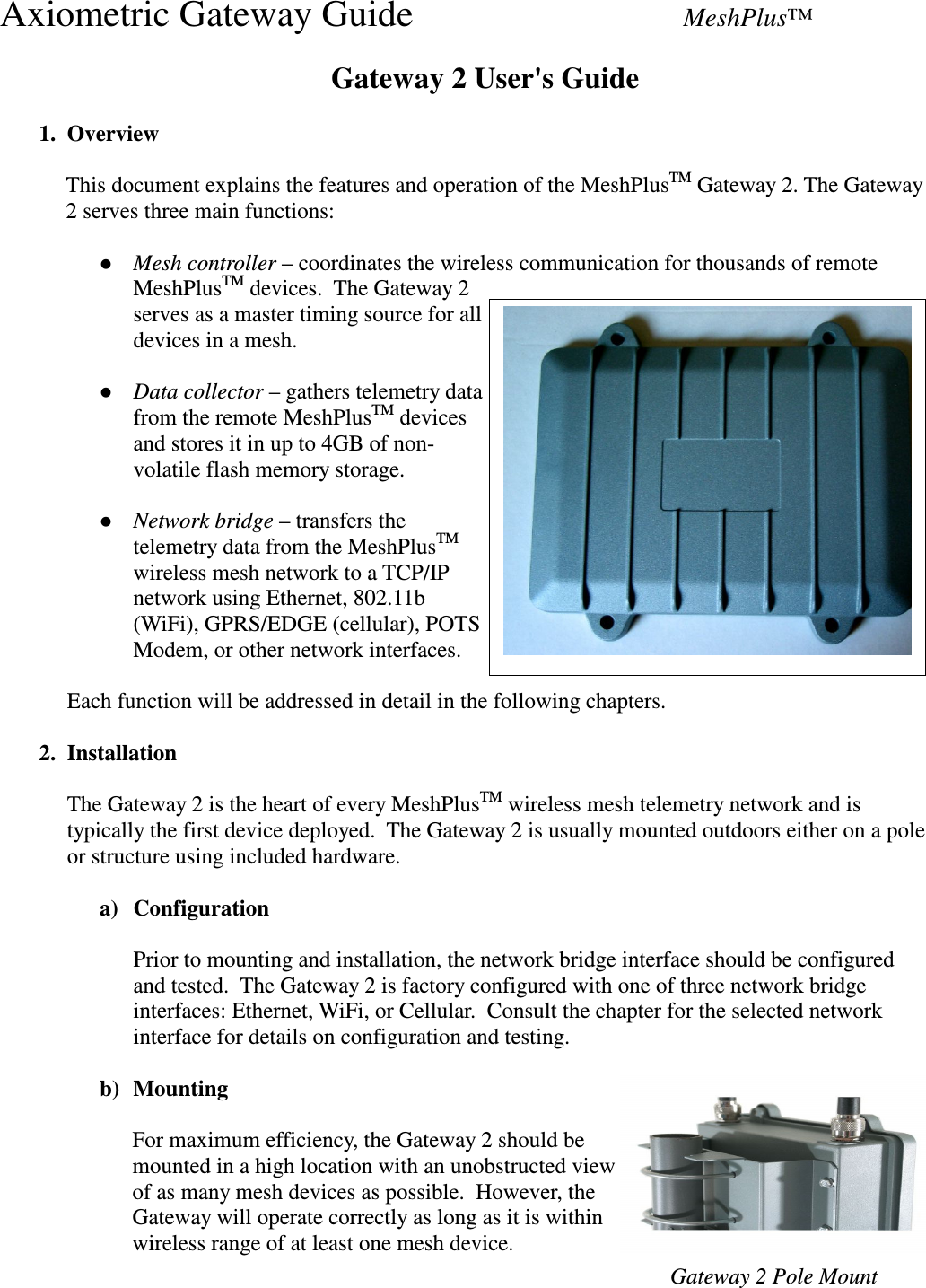
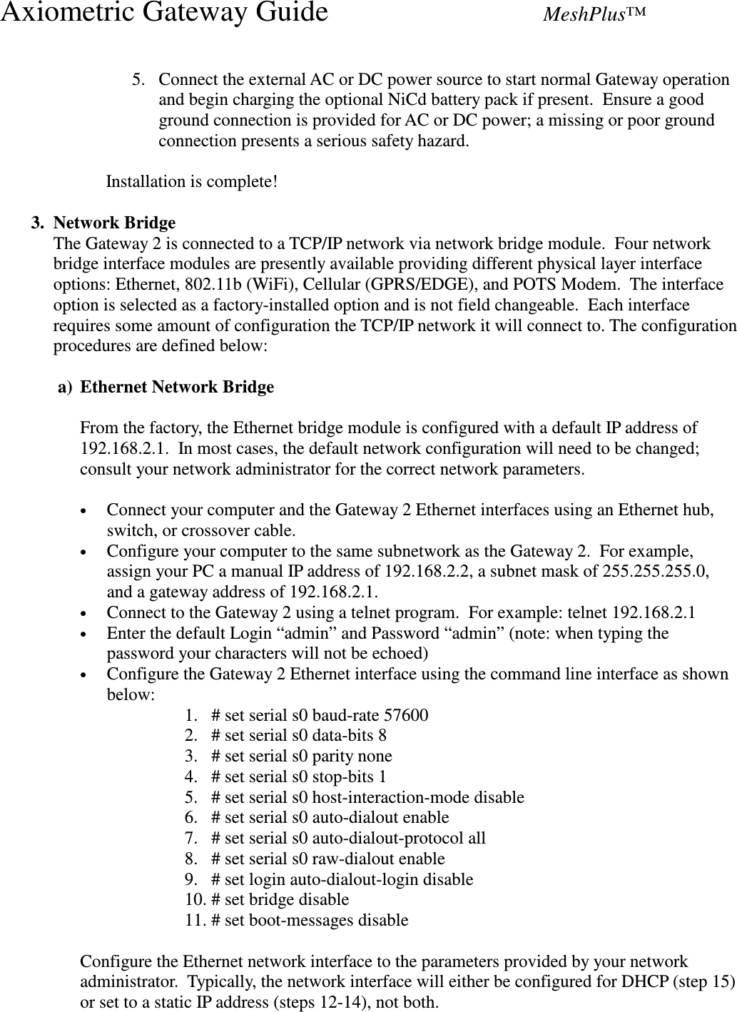
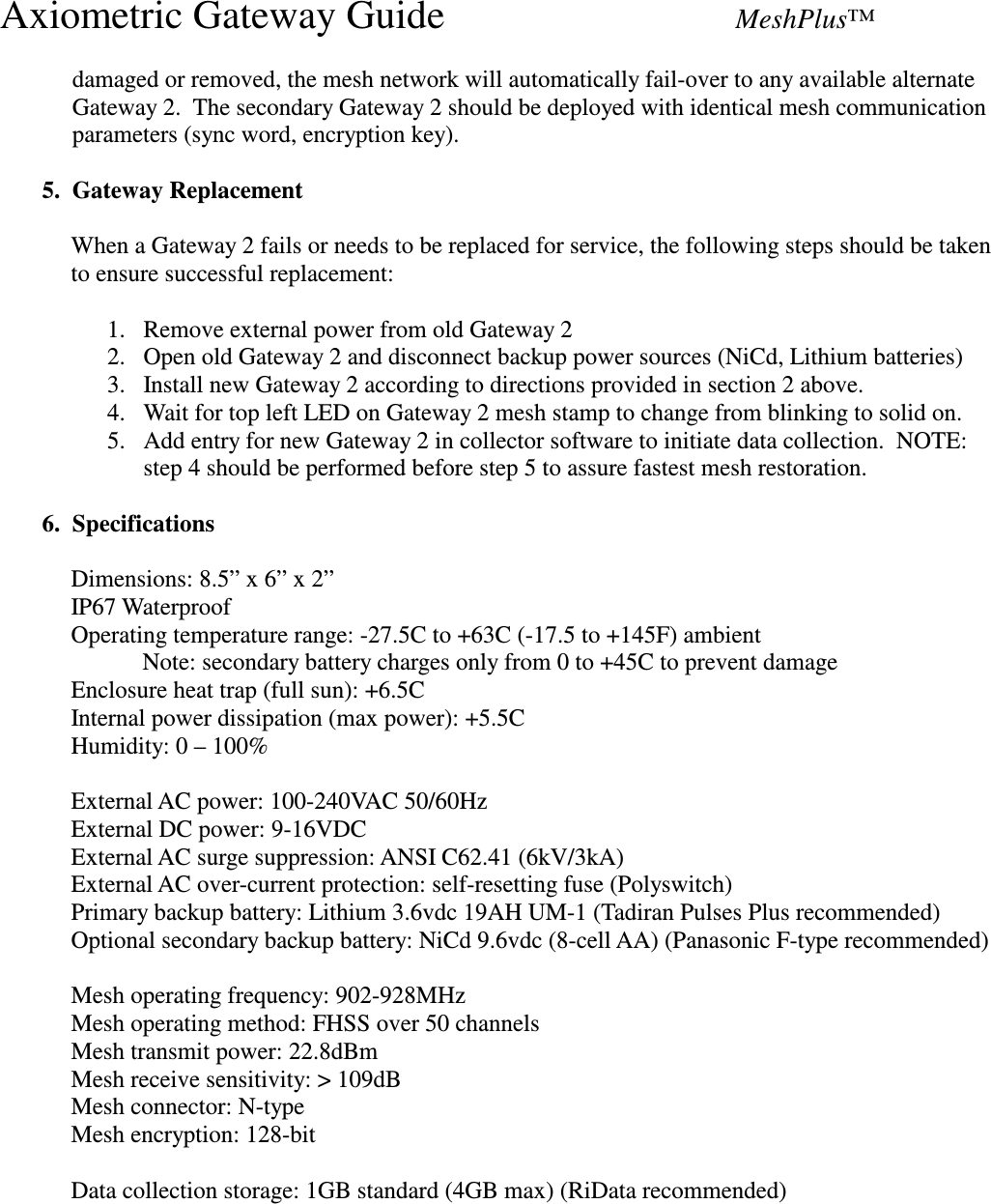
![Axiometric Gateway Guide MeshPlus™ • Steps 12-14 show how to configure the static IP address 172.30.1.31 and a subnet mask of 255.255.255.0 with a gateway at 172.30.1.1. You should use the parameters provided by your network administrator instead: 12. # set ip eth0 dhcp-client disable 13. # set ip eth0 ip-address 172.30.1.31 mask 255.255.255.0 14. # set ip def-gway 172.30.1.1 • Step 15 shows how to configure the Gateway 2 for DHCP: 15. # set ip eth0 dhcp-client enable • Finally configure the Gateway 2 for access on a particular TCP port (e.g. 2100 or substitute the port specified by your network administrator): 16. # set serial s0 auto-dialout-port 2100 17. # set ip hostname MyGW2name 18. # set ip auto-dialout enable 19. # set ip telnet raw-mode enable 20. # save • Other useful CLI commands: help exit restore default-config show config show serial s0 config show serial s0 statistics show sys-info set ip pri-dns <ip addr> set ip sec-dns <ip addr> set ip dns <enable/disable> set ip tcp-keepalive[3-120 minutes] (default = 3) show ip eth0 configuration show ip eth0 statistics show ip eth0 link-status <ping ip addr> (pings specified address) For additional CLI commands, consult the MultiTech Developer Guide MTXCSEM Commands. b) 802.11b (WiFi) Network Bridge From the factory, the WiFi bridge module is configured with a default SSID of “mt800swm”, infrastructure mode, no encryption and an IP address of 192.168.1.100. In most cases, the default configuration will need to be changed; consult your network administrator for the correct network parameters. In the example below, you will configure the Gateway2 for: • SSID=MeshPlus • IP Address = 172.30.1.34 • Subnetwork = 255.255.255.0](https://usermanual.wiki/Axiometric/GW2C-AC/User-Guide-859383-Page-6.png)
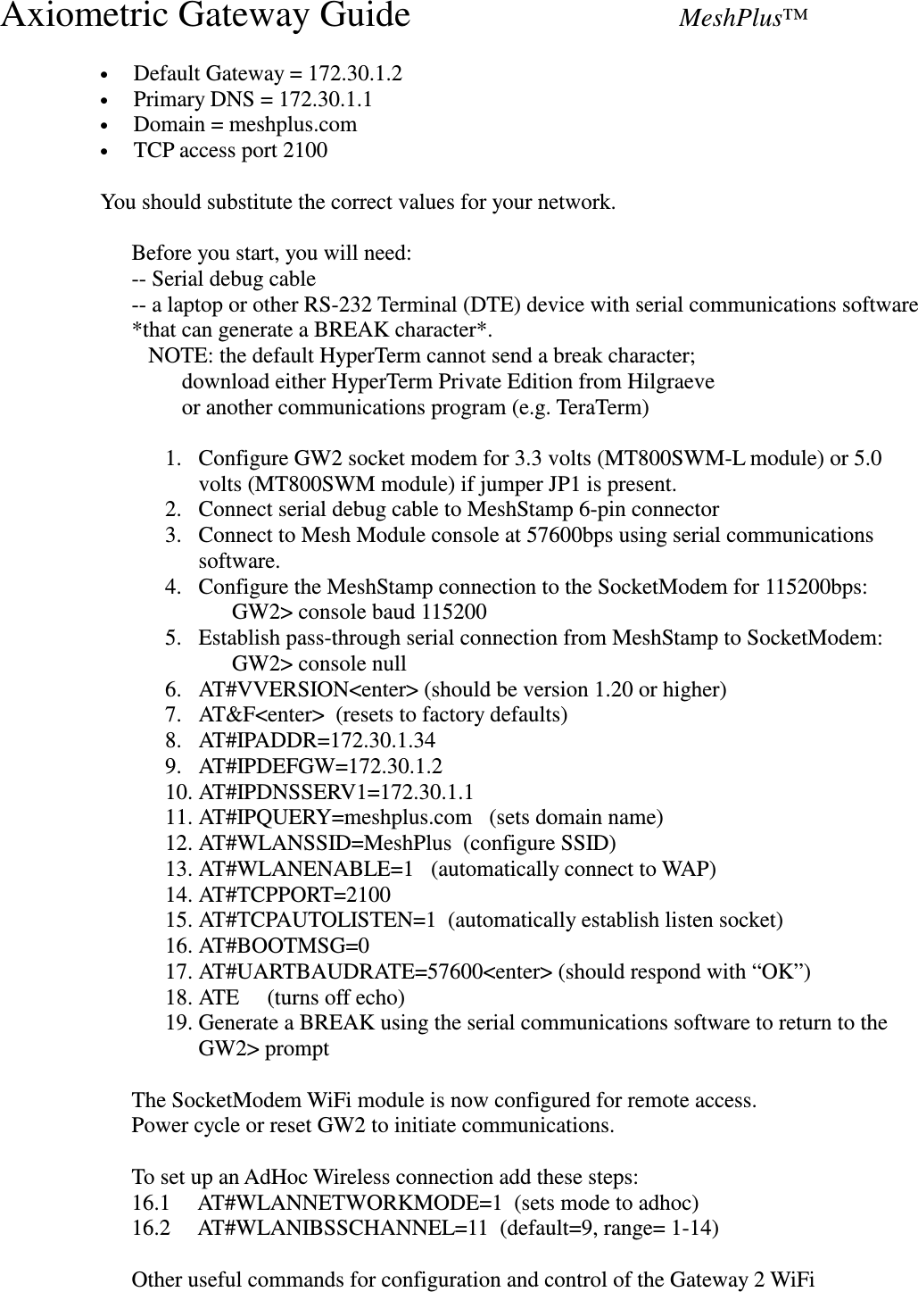
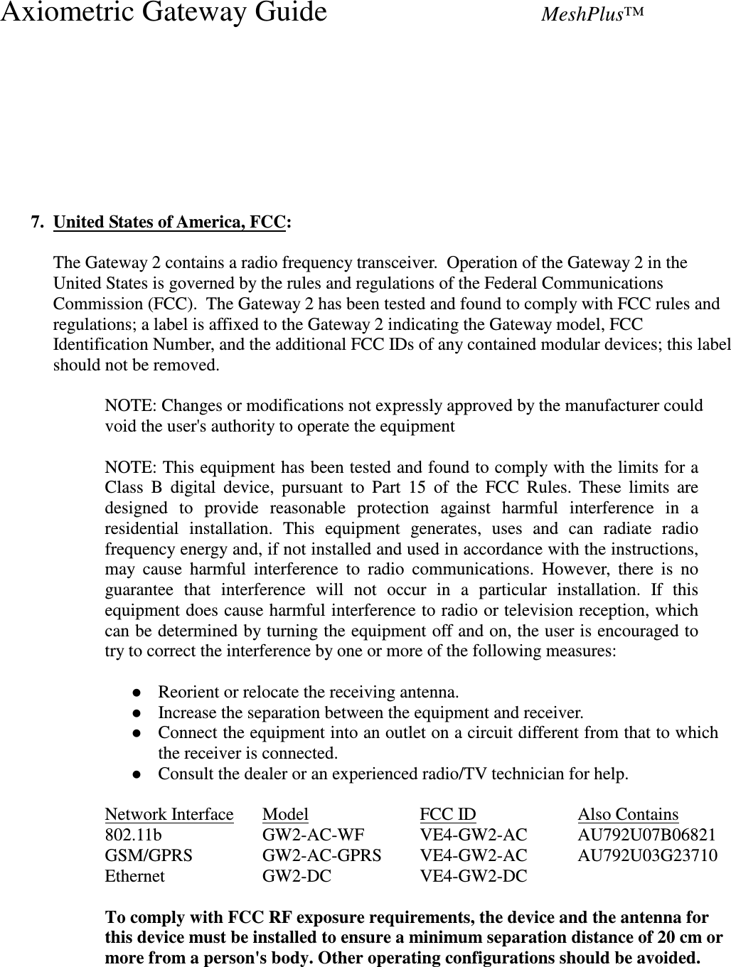
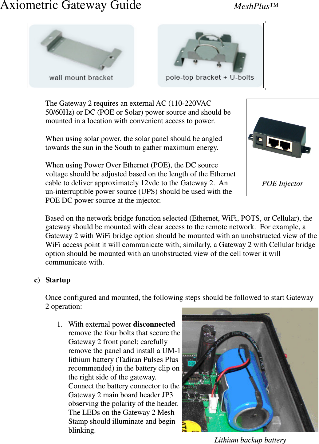
![Axiometric Gateway Guide MeshPlus™ functionality: “AT#IP?”, “AT#WLAN?”, “AT#VVERSION”, “AT#VSTATE”, “AT#VALL”, “AT&F” (restore factory defaults). Note that once this command sequence has been completed, any future changes to the WiFi configuration should skip step 4 since step 17 permanently configures the interface to 57600bps (the default). c) GPRS/EDGE Network Bridge Before you start, you will need: -- Serial debug cable -- a laptop or other RS-232 Terminal (DTE) device with serial communications softare *that can generate a BREAK character*. NOTE: the default HyperTerm cannot send a break character; download either HyperTerm Private Edition from Hilgraeve or another communications program (e.g. TeraTerm) -- Gateway 2 with SocketModem MTSMC-G-F2 for use in the USA -- activated SIM card for data account from Cingular or other carrier ---- (When setting up the account, you should specifically request: 'Mobile Terminating Data' and a 'Public Static IP Address' [If you don't ask for this, you won't get it; it is NOT the default]) -- Login information from Cingular for your specific SIM/Account: ---- APN (Access point name): (a string: e.g. 'wwan.ccs', 'cingular.isp') ---- APNUN (username): (e.g. "foobar@wwan.ccs") ---- APNPW (password): (e.g. "bwahahahaaaaaa!") ================================ Hardware Installation: -- Remove main power (POE, AC, etc.) from gateway -- disconnect backup power sources (Lithium/NiCd batteries) from Gateway 2 -- Remove JP1 (5v/3v3 selector near socket modem) if present -- verify Gateway stuffing option R2 is populated (1M-Ohm) and R1 is not. (this defaults SocketModem Enable line to true, and ensures GPRS connection stays up when the gateway is reset.) -- insert SIM card into socketmodem -- replace JP1, connecting the center pin to the "5V" side. -- reconnect backup power sources (lithium/nicad batteries) -- reconnect main power. -- wait ~10 seconds for everything to start-up. =============================== SocketModem One-Time Setup Establish communications with the SocketModem: -- connect to Gateway 2 console via console debug connector. (57.6kbps, 8N1, no flow ctrl.) Should see a 'GW2> ' prompt.](https://usermanual.wiki/Axiometric/GW2C-AC/User-Guide-859383-Page-8.png)
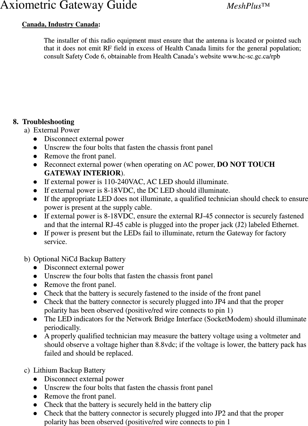
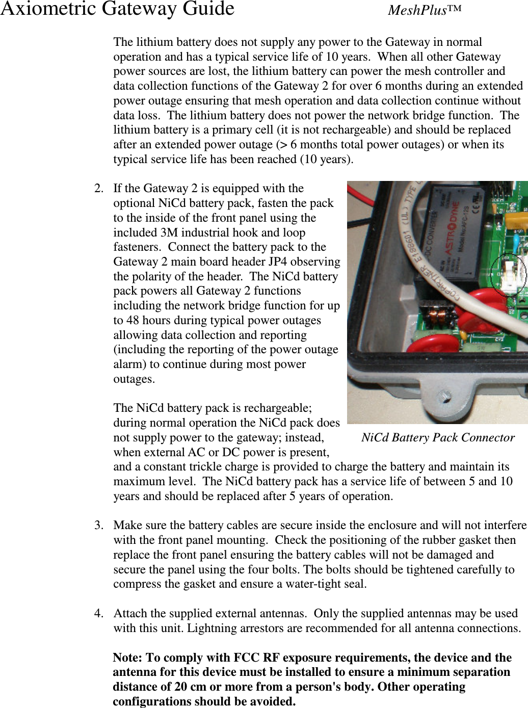
![Axiometric Gateway Guide MeshPlus™ -- setup passthrough to socketmodem: type: "console null<cr>" to relay typed characters directly to the SocketModem type: "AT<cr>" to cause modem to auto-baud (should see "OK" response) [note: you may have to do this two or three times] The SocketModem has on-board flash storage for most parameters; erase any non-volatile parameters to start from a clean slate. -- erase non-volatile storage on the SocketModem type: "AT&F" (wait for "OK") type: "AT&W" (wait for "OK") type: "AT+WOPEN=1" (wait for "OK") type: "AT#DELFLASH" (wait for "OK") -- wait 5 seconds -- remove JP1 -- wait 5 seconds -- replace JP1, again in the "5V" position -- wait for the RED led on the SocketModem to transition from SOLID to SLOW BLINK Configure permanent parameters on the SocketModem: NOTE: unless otherwise specified, assume "(wait for "OK)" after entering any 'AT' command. -- Fix the DTE rate to 57600bps: type: AT+IPR=57600 -- Fix the communications parameters to 8N1 type: AT+ICF=3,4 -- Set Gateway/SocketModem flow control to 'none' type: AT+IFC=0,0 -- Tell the SocketModem to always leave CD on: type: AT&C0 -- Tell SocketModem to switch to command mode when DTR goes from 1 to 0 type: AT&D1 -- Tell SocketModem to always keep DSR on: type: AT&S0 -- Save Modem Configuration: (Write to EEPROM) type: AT&W Advanced (IP or GPRS modem-specific) configuration -- turn on IP/GPRS stack type: "AT+WOPEN=1"](https://usermanual.wiki/Axiometric/GW2C-AC/User-Guide-859383-Page-9.png)
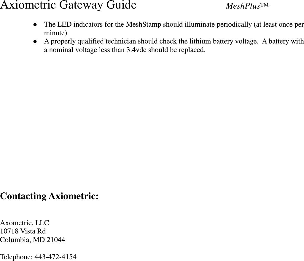
![Axiometric Gateway Guide MeshPlus™ (wait for "OK") -- Force attachment as class 'CG' [The default is a 'class B' device.] (GPRS-only - no voice service, no GSM service, auto-activate the IP stack, and auto-attach on power-up) type: AT+CGCLASS="CG" -- set DLE mode ON for connection ID 1 type: AT#DLEMODE=1,1 -- set TCP PORT for listen: type: AT#TCPPORT=1,2100 -- set TCP SERVER to allow incoming call from any host: type: AT#TCPSERV=1,"255.255.255.255" -- set DLE mode ON for connection ID 2 type: AT#DLEMODE=2,1 -- set TCP PORT for listen: type: AT#TCPPORT=2,2100 -- set TCP SERVER to allow incoming call from any host: OPTION: NORMAL: type: AT#TCPSERV=2,"255.255.255.255" OR, TO ENABLE BACKUP COLLECTOR: type: AT#TCPSERV=2,"64.32.161.115" -- set your APN, username, and password (wait for "OK" after each one) **** NOTE: double-and-triple check the username and password; Cingular mixes up ones and 'I's and 'L's and zeroes and 'o's in their passwords. **** NOTE: the quotes around strings, (e.g.username/password/apnserv are required) type: AT#APNSERV="your APN [e.g. wwan.ccs]" type: AT#APNUN="your username" type: AT#APNPW="your password" Once all the other configuration is done, turn off local echo and save that state to EEPROM: -- type: ate0 (wait for "ok") -- type: at&w (wait for "ok") Configuration is complete. Confirm connectivity with the Gateway2 prior to installation. d) POTS Modem Network Bridge The POTS modem bridge function is not supported in the current firmware 4. Redundant Configurations Multiple Gateway 2s may be deployed in a mesh for redundancy. If a primary Gateway 2 is](https://usermanual.wiki/Axiometric/GW2C-AC/User-Guide-859383-Page-10.png)