B plus B SmartWorx QTM85242000 Radio RF Modem, QTM-8524 User Manual man
B&B; Electronics Radio RF Modem, QTM-8524 man
Contents
manual

QTM-8524
2.4 GHz RF Radio Modem Module
Users Manual
QUATECH, Inc. TEL: (330) 434-3154
662 Wolf Ledges Pkwy FAX: (330) 434-1409
Akron, Ohio 44311 http://www.quatech.com
WIRELESS MODEM MODULE
FOR QTM-8000 SERIES SYSTEMS
QTM-8524
User’s Manual
Revision 1.0
PN

Warranty Information
Quatech Inc. warrants the QTM-8524 to be free of defects for one
(1) year from the date of purchase. Quatech Inc. will repair or replace any
system component that fails to perform under normal operating conditions
in accordance with the procedures outlined in this document, provided the
failure occurs during the one year warranty period. Any damage resulting
from improper installation, operation or general misuse voids all warranty
rights. No representation is made regarding the suitability of this product
for any particular purpose.
Please complete the following information and retain for your records.
Date of Purchase:
Model Number: QTM-8524
Product: 2.4 GHz RF Radio Modem_
Serial Number:
All products returned to Quatech for either warranty or non-
warranty repair MUST be assigned a Returned Material Authorization (RMA)
number prior to shipment. This RMA number must be clearly marked on the
exterior of the product’s return packaging and in any correspondence to
ensure proper routing and prompt attention. To obtain an RMA number,
contact the Quatech Technical Support Department at 1-800-553-1170 or
(330) 434-3154. In order to prevent damage to returned merchandise during
shipment, please package electronic components in anti-static/shock proof
materials.
For warranty repair/returns, please have the following information available
when contacting the Technical Support department:
1. Model number and serial number of the product under warranty,
2. Repair instructions and/or specific description of the problem.
For non-warranty repairs or upgrades, contact the Technical Support
department for current repair charges and please have the following
information available:
1. Purchase order number to cover the cost of the service,
2. Model number and serial number of the product,
3. Repair or upgrade instructions relative to the product.

Notice
The information contained in this document cannot be
reproduced in any form without the written consent of Quatech
Inc. Any software programs accompanying this document can
be used only in accordance with any licensing agreement(s)
between the purchaser and Quatech Inc. Quatech Inc. reserves
the right to change this documentation or the product to which
it refers at any time and without notice.
The authors have taken due care in the preparation of this
document and any associated software program(s). Every
attempt has been made to ensure accuracy and completeness.
Under no circumstances will Quatech Inc. be liable for damages
of any kind, incidental or consequential, in regard to or arising
from the performance or form of the materials presented herein
or in any software program(s) that may accompany this
document.
Quatech Inc. encourages and appreciates feedback concerning
this document. Please send any written comments to the
Technical Support Department at the address listed on the
cover of this manual.

Table of Contents
1. Introduction 9
1.1 Available QTM-8000 Series Modules 10
1.2 QTM-8000 Series Common Features 11
1.3 QTM-8000 Series Wireless Networks 12
1.3.1 Disadvantages of Conventional Two-Wire
RS-485 Networks 13
1.3.2 The QTM-8000 Series Network Advantage 14
1.3.3 Operation Principle 15
1.3.4 Supporting Multiple Baud Rates 16
1.4 QTM-8000 Series Module dimensions 17
2. QTM-8524 Specifications 20
2.1 Pin Assignments 20
2.2 QTM-8524 Module Specifications 21
2.3 QTM-8524 Block Diagram 22
2.4 QTM-8524 Disassembly 22
2.5 QTM-8524 Jumper Settings 24
2.6 QTM-8524 Basic Wire Connections 26
2.6.1 RS-232 Connection Between PC and QTM-8524 26
2.6.2 Connecting QTM-8000 Modules to the QTM-8524 26
3. Antennas 27
3.1 QTM-8524 Antenna Options 27
3.1.1 QTM-24ANT-SW Specifications 27
3.1.2 QTM-24ANT-C Specifications 28
3.2 Connecting Antennas to QTM-8524 Modules 29
3.2.1 Site Selection 29
3.2.2 Installation 29
3.2.3 Connection 29
3.3 Mounting External Antennas 30
3.3.1 Mounting the QTM-24ANT-SW 30
3.3.2 Mounting the QTM-24ANT-C 32
3.3.3 RF Safety 34

4. Configuration 34
4.1 RS-232 or RS-485 Configuration 34
4.2 Half-Duplex and Full-Duplex Operation 34
4.3 Synchronous and Asynchronous Communication 35
4.4 Configuration Modes 36
4.4.1 Mode 1: Full-Duplex, Synchronous 37
4.4.2 Mode 2: Half-Duplex, Synchronous 38
4.4.3 Mode 3: Full-Duplex, Asynchronous 39
5. Application Examples 40
5.1 Peer-to-Peer Communication (Mode 1) 40
5.2 Interfacing with QTM-8000 Modules (Mode 1) 41
5.3 Multiple PC Communication (Mode 2) 42
5.4 Asynchronous Communication (Mode 3) 43
6. Approvals 44

List of Figures
1.3 QTM-8000 Series Network with Multiple Baud Rates
and Multiple Data Formats 12
1.3.2.1 Single Baud Rate QTM-8000 Wireless Network 13
1.3.2.2 Multi-Baud Rate Wireless QTM-8000 Network 14
1.4.1 QTM-8000 Series Front, Side, Rear and Top Views 17
1.4.2 QTM-8000 Series DIN Rail Mounting 18
1.4.3 QTM-8000 Series Panel Mounting 19
2.3 QTM-8524 Block Diagram 22
2.4 Disassembling the QTM-8524 23
2.5 QTM-8524 Jumper Settings 25
2.5.1 Connecting QTM-8524 to DB-9 Serial Cable 26
2.5.2 Connecting QTM-8524 to QTM-8000 I/O Modules 26
3.1.1 QTM-24ANT-SW Transmission Pattern 27
3..1.2 QTM-24ANT-C Transmission Pattern 28
3.3.1.1 Mounting the QTM-24ANT-SW Steps 1-6 30
3.3.1.2 Mounting the QTM-24ANT-SW Step 7 31
3.3.2.1 Installing the QTM-24ANT-C Ceiling Mount Bracket 33
3.3.2.2 Connecting the QTM-24ANT-C Antenna to the Bracket 33
5.1 QTM-8524 Peer-to-Peer Communication 40
5.2 QTM-8524 as part of a QTM-8000 Series I/O Network 41
5.3 QTM-8524 Modules Used to Network Multiple PCs 42
5.4 QTM-8524 Modules in an Asynchronous Network 43

Quatech QTM-8524 Manual 9
1. Introduction
The QTM-8000 Series of modules is comprised of analog and
digital I/O modules designed for a wide variety of data ac-
quisition and signal conditioning functions. These modules
are designed for an RS-485 communication network, and re-
quire an RS-485 to RS-232 converter in order to be accessed
through a standard PC serial port. The QTM-8520/8520R
module performs this function. Unlike many other convert-
ers, the versatile QTM-8520 contains a unique self-tuner ASIC
that allows it to process signals from multiple serial devices
operating at different baud rates and using different data for-
mats. This flexibility makes a QTM-8000 Series network an
extremely cost effective solution for remote signal monitoring
and control.
The QTM-8524 is a radio modem module that can implement
QTM-8000 Series modules as a wireless data acquisition and
signal conditioning network. The wireless communication
modules form RF communication between peer-to-peer or
multi-point structures, which eliminates the use of long cables.
Like the QTM-8520, the QTM-8524 functions as a RS-485 to
RS-232 converter. However, it does not contain the self-tuner
ASIC which means that all modules operating in a QTM-8524
wireless network must be functioning at the same baud rate
and using the same data format. To implement a wireless net-
work functioning at several different baud rates, a QTM-8520
module must be used in conjunction with multiple pairs of
QTM-8524 modules.
10 Quatech QTM-8524 Manual
1.1 Available QTM-8000 Series Modules
Wireless Radio Modem Modules:
QTM-8524: 2.4 GHz RF to RS-232 or RS-485 converter
Bus Conversion and Repeater Modules:
QTM-8520: RS-232 to RS-485 converter with 3000V isolation
QTM-8520R: RS-232 to RS-485 converter with 3000V isolation
QTM-8510: RS-485 to RS-485 repeater with 3000V isolation
Digital I/O Modules:
QTM-8050: 7 digital input s, 8 TTL compatible digital outputs
QTM-8052: 8 isolated digital input channels
QTM-8060: 4 isolated digital inputs, 4 digital relay outputs
Analog Output Modules:
QTM-8021: Single channel analog (current or voltage) output
Analog Input Modules:
QTM-8013D: Single channel RTD analog input
QTM-8014D: 1 analog input, 1 digital input, 2 digital outputs,
with LED display.
QTM-8017: 8 channel analog input module
QTM-8018: 8 channel thermocouple input module
Timer/Counter Modules:
QTM-8080D: 2 independent 32-bit counters,
2 digital output channels
5 Hz to 50kHz frequency measurement range
Quatech QTM-8524 Manual 11
1.2 QTM-8000 Series Common Features
Communication :
❍Asynchronous half-duplex 2-wire RS-485 network
❍Maximum network distance without repeater=4000 feet (1.2Km)
❍Baud Rates: 600,1200,2400,4800,9600,19200,38400,57600 (bps)
❍A single network can accommodate multiple devices with different
baud rates and data formats
❍QTM-8000 series data format=
1 start + 8 data + 1 stop + no parity = 10-bit
❍Two extra checksum bytes can be enabled or disabled
❍Built-in transient voltage suppressor and PTC protector
❍ASCII command/response protocol
❍Plug-in screw terminal block
Power :
❍+10V ~ +30V DC
❍Power reverse protection, over-voltage brown-out protection
System :
❍Internal Dual watchdog, power-on start value and safe value
for host failure
❍Operating temperature : -10 to 70ºC (14 to 185ºF)
❍Storage temperature : -25 to 80ºC (-13 to 185ºF)
❍Humidity : 5 to 95%, non-condensing
❍Isolation voltage : 3000 VDC
12 Quatech QTM-8524 Manual
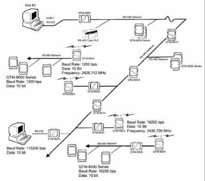
1.3 QTM-8000 Series Wireless Networks
Figure 1.3--QTM-8000 Series Network with multiple baud rates
and multiple data formats
Quatech QTM-8524 Manual 13
1.3.1 Disadvantages of Conventional Two-Wire RS-485
Networks:
In a standard RS-485 network, a converter is used to adapt the host PC’s
single wire RS-232 signal to the two-wire RS-485 signal required by the
network. However, when using a standard converter, not only must the
baud rate and data format for all signals remain fixed, but they must be
identical for all incoming signals. This can pose a problem if multiple types
of devices are to be used in a single system, such as a QTM module operating
at 115200 bps with a 10-bit per channel data format, and a standard PLC
operating at 9600 bps with an 11-bit data format. One solution to this
problem is to use two independent two-wire RS-485 networks to accommo-
date both devices. However, this can increase overall system cost and de-
crease system reliability. If devices are capable of operating at different baud
rates, but share a single data format, a single standard two-wire RS-485
network can be used, provided that all devices are set to use the lowest
common baud rate. While this solution may save on system cost, it is at the
expense of performance.
1.3.2 The QTM-8000 Series Network Advantage:
The most desirable system is one in which a single RS-485 network can be
used to link devices operating at multiple baud rates with different data
formats. The QTM-8000 Series can do just that. Using the QTM-8520 con-
verter module to auto-tune the network, up to 256 devices operating between
1200 and 115200 bps can be controlled via a single standard RS-232 serial
port. (Using a QTM-8510 repeater expands the network to 2, 048 devices.)
For wireless networks, the QTM-8524 can convert and control the RS-485
network. However, a single baud rate, channel, and frequency must be jumper
selected for each module pair. This means that if a QTM-8524 is connected
directly to the computer’s serial port, the network can only function at a
single baud rate. To support multiple baud rates in a QTM-8000 wireless
network, the QTM-8520 must be used in conjunction with a pair of QTM-
8524 RF modules for each desired baud rate. (See figures 1.3.2.1 & 1.3.2.2)
Figure 1.3.2.1--QTM-8000 Series Network using a single pair of
QTM-8524 modules as an interface to the PC.
Baud Rate=19.2 kbps
14 Quatech QTM-8524 Manual
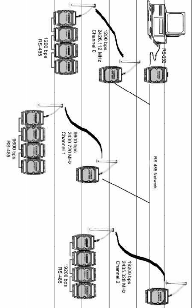
Figure 1.3.2.2--Using a QTM-8520 converter
module in conjunction with multiple pairs of
QTM-8524 modules to support multiple baud rates
in a wireless QTM-8000 Series network
Quatech QTM-8524 Manual 15
1.3.3 Operation Principle (Refer to Figure 1.3.2.1 & 1.3.2.2):
(1) The Host PC sends out a command via COM1.
(2) The QTM-8520 or upstream QTM-8524 converts the RS-232 signal into
a RS-485 signal or a RF signal respectively.
(3) All modules connected to the RS-485 network will simultaneously
receive this command. Each module in the network will extract the
destination address field and compare this value to its local module
address. The receiving wireless module first converts the RF signal to
RS-485, then sends the command to the downstream modules.
(4) The module to which the command was addressed will execute it, and
the other modules will ignore the command.
(5) After executing the command, the addressed module sends a response
back to the host PC over the RS-485 or RS-485/RF network.
(6) The QTM-8520 or upstream QTM-8524 module processes the response
and converts it from RF/RS-485 to RS-232 for use by the Host PC
(7) Host PC will interpret this result and take appropriate action.
16 Quatech QTM-8524 Manual
1.3.4 Supporting Multiple Baud Rates
As noted earlier, QTM-8000 Series networks support devices operating at
different baud rates. For example, in Figure 1.3 the diagram depicts a wire-
less modem operating at 19200 bps, QTM-8000 Series modules operating at
2400 bps and a PLC operating at 9600 bps. The QTM-8520 converter module
can automatically switch to any baud rate in the 1200 bps to 115,200 bps
range.
In order to support multiple baud rates in a wireless network, the QTM-8520
must be used to auto tune the network and pairs of QTM-8524 RF modules
are jumper configured to match the specific baud rate at which downstream
modules are operating. When the host PC sends commands it tailors them
to the baud rate at which the target module is operating. The QTM-8520
drives the signal from RS-232 to RS-485 at that given baud rate. The QTM-
8524 that is configured for that same baud rate receives the RS-485 com-
mands and converts them to RF. Any other QTM-8524 set for a different
baud rate will ignore the command. The RF signal is transmitted along a set
channel as selected on the QTM-8524. The downstream QTM-8524 that is
configured for that same channel receives the RF signal and converts the
commands to RS-485. These commands are then distributed to all the mod-
ules downstream from the receiving QTM-8524. Each module at the target
baud rate will determine whether the command is addressed to it (see step 3
in section 1.3.3) and react appropriately.
Quatech QTM-8524 Manual 17
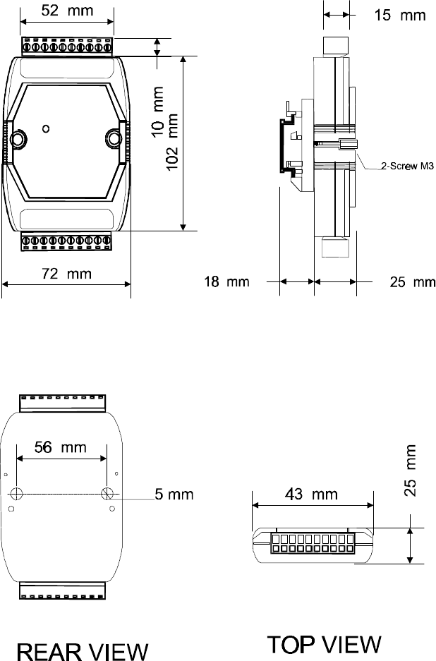
1.4 QTM-8000 Series Module Dimensions
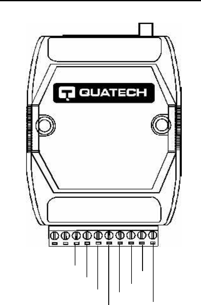
Figure 1.4.1--QTM-8000 Series Front, Side, Rear, and Top Views
FRONT VIEW SIDE VIEW
18 Quatech QTM-8524 Manual
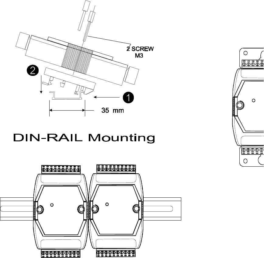
Figure 1.4.2--QTM-8000 Series Din Rail Mounting
Quatech QTM-8524 Manual 19
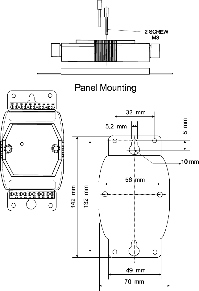
Plastic Part for
Panel Mount
Figure 1.4.3--QTM-8000 Series Panel Mounting
20 Quatech QTM-8524 Manual
2. QTM-8524 Specifications
2.1 Pin Assignments
QTM-8524
Wireless RF Modem
Frequency Range: 2.4 GHz
Channel Spacing: 2 MHz
RF Power Output: 0.707W
Interface: RS-232/RS-485
11
20
1
10
(RS-485)
DSR
RX
TX
Computer
GND
(Y)D+
(G)D-
(R)+Vs
Power
GND

Quatech QTM-8524 Manual 21
QTM-8524: 2.4 GHz RS-232/RS-485 to RF Converter
RF Communication Transceiver
Frequency Band: 2426 to 2458 MHz
Channel Spacing: 2.048 MHz (8 Channels jumper select)
Peak Output Power: 28.5 dBm ±2 dB (.707 watts)
Modulation: Gaussian Minimum Shift Keying (GMSK)
Time Division Duplexing
Transmission Range: RS-232
Line of Sight: .35 miles
Semi-Open: 150 ft.
Direct Sequence Spread Spectrum
Non-Overlapping Channels: 8 Channels, Jumper selectable
(Full-Duplex Mode Only)
Modes of Operation: Full Duplex or Half Duplex, Jumper selectable
Communication: Asynchronous or Synchronous, Jumper selectable
Serial Communication Interface
RS-232 (TxD, RxD, GND) or RS-485 (D+, D-), Jumper selectable
Baud Rate: 600 bps to 57.6 kbps, Jumper selectable
Environments
Operating Temperature: 0 °C to 50 °C
Storage Temperature: -30 °C to 70 °C
Power Supply
Vs: +10V to +30V DC Unregulated
Power Consumption: 1.5W
2.2 QTM-8524 Module Specifications
Note: The QTM-8524 must operate in full-duplex,
synchronous mode in order to be used with
QTM-8000 Series data acquisition and signal
conditioning modules.
22 Quatech QTM-8524 Manual
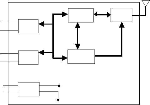
TX
RX
D+
D-
+Vs
GND
RS-232
Interface
RS-485
Interface
Power
Regulator
Embedded
Controller
Transceiver GMSK
RF
Module antenna
+5V
QTM-8524
2.3 QTM-8524 Block Diagram
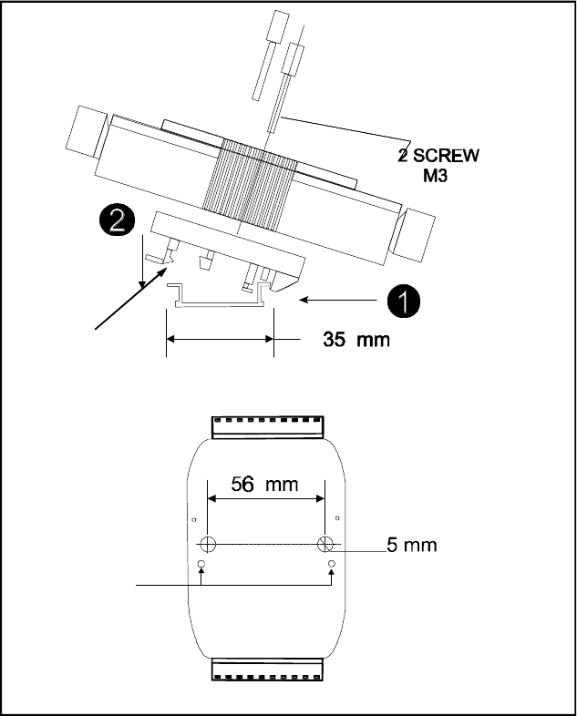
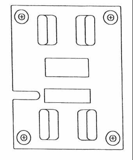
2.4 QTM-8524 Disassembly
Disassembly of the QTM-8524 is required to change the jumper settings.
Please refer to figure 2.4 and follow the steps below to disassemble the
module:
1. Remove the DIN rail mounting bracket by
loosening the screws on the front of the unit.
2. Remove the two (2) small screws that were
under the DIN rail mounting bracket.
3. Using a small flat bladed screwdriver, gently pry
at the corners to separate the plastic case.
4. Set the jumpers as desired and replace the radio
assembly in the case. Use care not to flex the
cable too much while setting the jumpers.
Figure 2.3--QTM-8524 Block Diagram
Quatech QTM-8524 Manual 23
5. Snap the case back together firmly.
6. Insert the two (2) small screws in the back of the unit.
7. Place the DIN rail bracket back (notice locating
pins on the bottom of the bracket) and secure tightly.
Remove for
disassembly
Remove for
disassembly
REAR VIEW
Figure 2.4--Disassembling the QTM-8524
24 Quatech QTM-8524 Manual
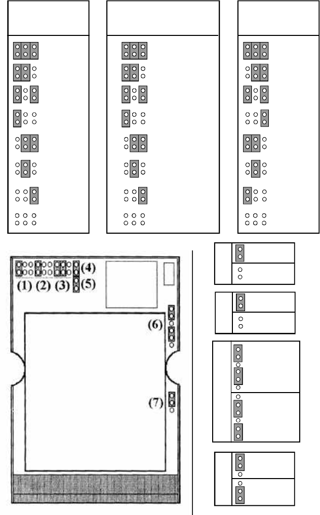
2.5 QTM-8524 Jumper Settings
Factory default jumper settings are indicated below.
·Channel 3
·Baudrate (bps) = 9600 bps
·Slave Mode
·RS-232 Interface
·Frequency Channel = 2439.936 MHz
·Full Duplex Mode
·Synchronous Communication
Figure 2.5 on the following page diagrams the other possible jumper set-
tings. See section 4 for more information about how QTM-8524 modules
should be configured for different types of QTM-8000 wireless networks.
Note that the QTM-8524 must be disassambled before jumper settings can
be changed. See section 2.4 for disassembly instructions.
Quatech QTM-8524 Manual 25
2426.112 MHz
2430.720 MHz
2435.328 MHz
2439.936 MHz
2444.544 MHz
2449.152 MHz
2453.760 MHz
2458.368MHz
(2) Frequency
Select
Channel0
Channel1
Channel2
Channel3
Channel4
Channel5
Channel6
Channel7
(1) Channel
Select
600 bps
1200 bps
2400 bps
4800 bps
9600 bps
19200 bps
38400 bps
57600 bps
(3) Baud Rate
Select
(4) Full-Duplex
Half-Duplex
(5) Slave
Master
(6)
Synchronous
Asynchronous
(7) RS-232
RS-485
QTM-8524
Figure 2.5.--QTM-8524 Jumper Settings
26 Quatech QTM-8524 Manual
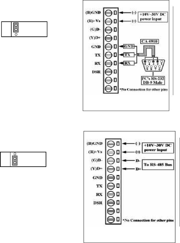
2.6 QTM-8524 Basic Wire Connections
(1) Position Jumper 7 to RS-232
as shown
(2) Connect QTM-8524 GND, TX
and RX to CA-0910’s corre-
sponding RS-232 GND, TX and
RX
(3) Connect CA-9010’s DB-9 female
connector to the PC’s RS-232
DB-9 male connector
2.6.1 RS-232 connection between PC and QTM-8524
(1) Position Jumper 7 to RS-485
as shown
(2) Connect QTM-8524 D+ to D+ of
QTM-8000 RS-485 network
(3) Connect QTM-8524 D- to D- of
QTM-8000 RS-485 network
2.5.2 Connecting QTM-8000 modules to the QTM-8524
(7) RS-232
(7) RS-485
Figure 2.6.2--Connecting QTM-8524
to QTM-8000 Modules
The QTM-8524 includes a cable that will allow you to connect your wireless
module directly to a PC. One end of the cable provides a standard D-9
connector that plugs into a computer’s standard serial port. The other end
has exposed wires used for connecting with the QTM-8524. Follow the
instructions below to wire the module to the cable.
Figure 2.6.1--Connecting QTM-8524
to DB-9 Serial Cable
Quatech QTM-8524 Manual 27
3. Antennas
Two antennas are available for use with the QTM-8524. The standard an-
tenna, QTM-24ANT-SW, is for general purpose indoor/outdoor applica-
tions, and can be conveniently wall-mounted on a swivel bracket. The op-
tional monopole antenna, QTM-24ANT-C is ideal for office/lab applica-
tions and can be easily mounted on the ceiling.
3.1 QTM-8524 Antenna Options
3.1.1 QTM-24ANT-SW Specifications
Standard Wall-Mount Antenna
Type: Patch
Mount: Swivel bracket
Application: General Purpose
Gain: 7.5dBi
Frequency: 2.4 GHz
Transmission Range: 500 Meters, open line-of-sight (50M with barriers)
Included Accessories: cable, hardware and connector
Figure 3.1.1--QTM-24ANT-SW Transmission Pattern
28 Quatech QTM-8524 Manual
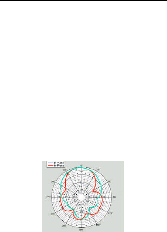
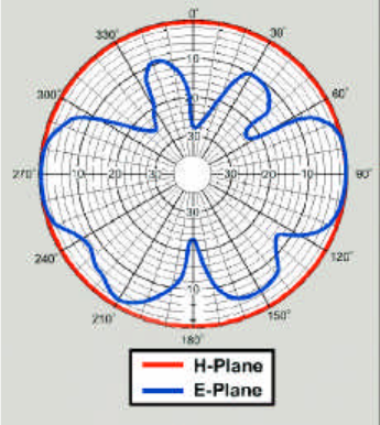
3.1.2 QTM-24ANT-C Specifications
Ceiling-Mount Antenna
Type: Monopole
Mount: Ceiling
Frequency: 2.4 GHz
Gain: 3dBd
Weight: 0.29lb ( 0.64 kg)
Height: 9 in (22.9 cm)
Nominal Impedance: 50 Ohms
VSWR: 1.5:1 nominal
Transmission Range: 500 Meters, open line-of-sight (50M with barriers)
Radiating Element: Plated copper laminate
Enclosure: Polycarbonate
Application: Office/lab, drop ceiling, transmission
Included Accessories: cable, hardware and connector
Figure 3.1.2--QTM-24ANT-C Transmission Pattern

Quatech QTM-8524 Manual 29
3.2 Connecting Antennas to QTM-8524 Modules
Your QTM-8524 is issued with a high quality communication antenna. To
get the maximum performance form your wireless system, please follow
the directions and suggestions that follow.
3.2.1 Site Selection
Antenna location is extremely important when installing your system. If
possible, try to keep the antenna away from any obstructions. Objects and
structures made of metal will reduce the efficiency of the antenna. Also,
keep in mind that systems like cellular phone repeaters, other wireless LANs,
and microwave ovens may interfere with the QTM-8524. If you encounter
problems with one frequency, try changing the frequency at which your
QTM-8524 modules are operating. Eight (8) different frequencies can be
selected using jumper 2 on the module (see Figure 2.4 for a diagram of QTM-
8524 jumper settings.).
3.2.2 Installation
Install the antenna and module as per the directions. See section 3.3.1 for
detailed QTM-24ANT-SW installation instructions and section 3.3.2 for de-
tailed QTM-24ANT-C installation instructions. Be sure to mount the an-
tenna BEFORE connecting it to the QTM-8524 module. The QTM wireless
system should be professionally installed.
3.2.3 Connection
Both antennas are supplied with SMA connectors attached to the antenna
cable. These connectors are designed for optimum use at high frequencies.
To connect the antenna to the module, carefully press the connectors to-
gether and use your fingers to rotate the coupling net clockwise to tighten.
DO NOT over-tighten the connection. A 5/16” open ended wrench can be
used to secure the connection just a little past “finger-tight,” but no more.
Over-tightening the connection may damage the mating surfaces of the con-
nector, and reduce the performance of your wireless system. Use care not to
cross-thread the connector. If you feel resistance when tightening, back the
coupling nut off and try again.
If the connectors need to be cleaned, use a clean cotton swab and a little pure
alcohol. Let the alcohol dry before reconnecting. DO NOT saturate the
connector with any liquid. DO NOT use any lubricants on the connector.
Warning: The FCC strictly prohibits connecting any other
antenna to the QTM-8524. Only Quatech supplied an-
tennas are approved by the FCC for use with this mod-
ule. Use of any other antenna will void your warranty.
30 Quatech QTM-8524 Manual
3.3 Mounting External Antennas
To reduce potential radio interference to other users, the antenna type and
its gain should be chosen so that the equivalent isotropically radiated
power (EIRP) is not more than that required for successful communication.
3.3.1 Mounting the QTM-24ANT-SW
Please refer to Figures 3.3.1.1 - 3.3.1.3 and follow the instructions below to
mount your QTM-24ANT-SW antenna. Be sure to mount the antenna
BEFORE connecting it to the QTM-8524 module. The QTM-24ANT-SW
should be professionally installed.
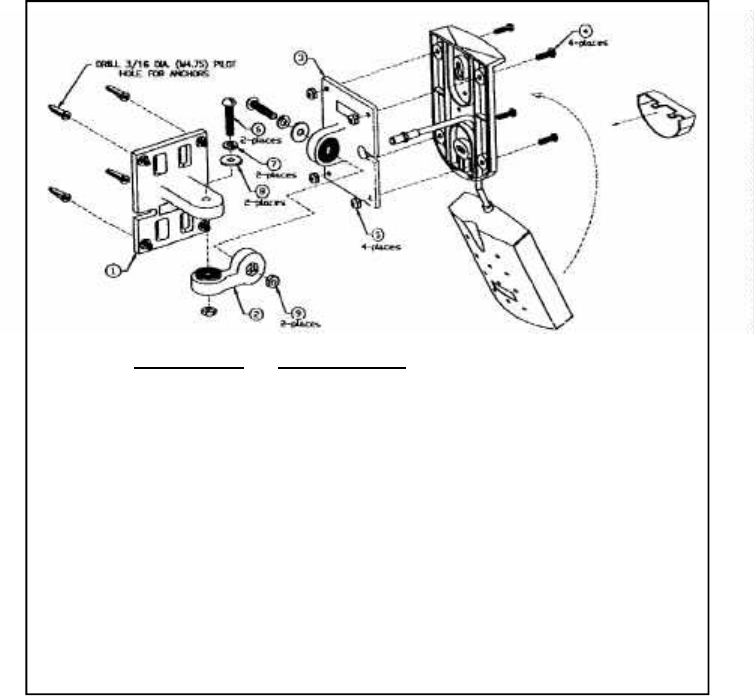
Reference Description
1 Molded Wall/Mast Mount
2 Molded Articulating Arm
3 Molded Antenna Mount
4 #8-32 x 5/8 Machine Screw
5 #8-32 SS/Nylon Hex Nut
6 1/4-20 x 1-1/4 Machine Screw
7 1/4 SS Split Lock Washer
8 1/4 SS Flat Washer
9 1/4-20 SS Hex Nut
Figure 3.3.1.1 Mounting the QTM-24ANT-SW Steps 1 - 6
Quatech QTM-8524 Manual 31
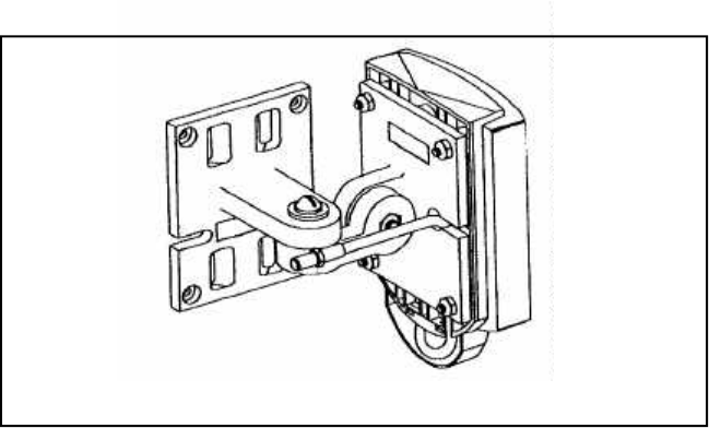
Figure 3.3.1.2-- Mounting the QTM-24ANT-SW Step 7
(1) Route the antenna cable through the mounting plate as shown in Fig-
ure 3.3.1. DO NOT snap the antenna to the mounting plate yet.
(2) Secure the molded antenna mount to the mounting plate as shown in
Figure 3.3.1. 1 Use the #8-32 x 5/8” machine screws and the #8-32 SS/
Nylon hex nut as shown.
(3) Snap the antenna into the mounting plate (dashed lines) as shown in
Figure 3.3.1.1
(4) Secure the articulated arm to the molded antenna mount using a
1/4-20 x 1-1/4” machine screw, a 1/4” flat washer. a 1/4” lock washer,
and a 1/4-20 SS hex nut as shown in Figure 3.3.1.1.
(5) Secure the molded wall/mast mount to the articulating arm using a
1/4-20 x 1-1/4” machine screw, a 1/4” flat washer, a 1/4” lock washer,
and a 1/4-20 SS hex nut as shown in Figure 3.3.1.1.
(6) Adjust the length of the cable to minimize the exposed cable loop.
(7) Place the cable guard over the exposed cable and snap it in place, as
shown in Figure 3.3.1.2.
(8) To mount the assembly, drill four (4) 3/16” diameter (M4.75) pilot holes
for the wall anchors. Use the molded wall/mast mount as a template to
drill your holes. Or, cut out the hole template provided on page 45.
(9) Loosen the screws in the boom arm to adjust the antenna position.
Tighten the screws when the optimum position is determined.
32 Quatech QTM-8524 Manual
3.3.2 Mounting the QTM-24ANT-C
Safety
The QTM-24ANT-C antenna has been designed to attach to and hang from
standard ceiling panel runners. To prevent personal injury or equipment
damage, the antenna must be securely mounted per the following instruc-
tions. The QTM-24ANT-C should be professionally installed.
Location
The location at which the QTM-24ANT-C is mounted is very important.
Objects such as metal columns, walls, etc. will reduce efficiency. Best perfor-
mance is achieved when transmit and receive antennas are mounted at the
same height, and in a direct line of sight with no obstructions. If this is not
possible, and reception is poor, it is a good idea to try a few different mount-
ing positions to optimize reception.
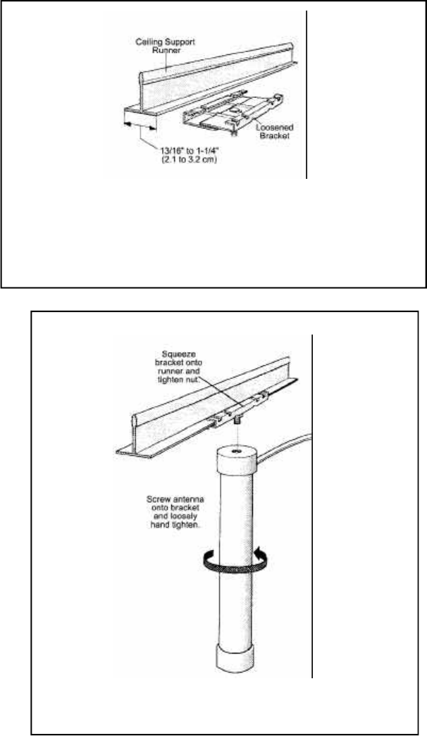
Mounting
The QTM-24ANT-C is suitable for use indoors or outside. The antenna
bracket fits ceiling support runners 13/15” to 1-1/4” (2.1 to 3.2 cm) wide.
To install the antenna, follow the steps below:
(1) Loosen the 1/4-20 hex nut and position the antenna mount over the
support runner. (See Figure 3.3.2.1).
(2) Squeeze the bracket firmly onto the runner (hand-pressure is adequate)
and tighten the hex nut securely as shown in Figure 3.3.2.2
(3) Carefully screw the antenna onto the 1/4-20 screw (lightly hand-
tighten) as shown in Figure 3.3.2.2
(4) Secure coaxial cable along the support runner using tape or cable ties.
If a different mount is used, limit the depth it is threaded into the mounting
hole to .35 inches (.9 cm). For outdoor mounting, install the antenna with the
threaded hole down.
Quatech QTM-8524 Manual 33
Figure 3.3.2.1-- Installing the QTM-24ANT-C
Ceiling Mount Bracket
Figure 3.3.2.2-- Connecting the QTM-24ANT-C
Antenna to the Ceiling Mount Bracket

34 Quatech QTM-8524 Manual
4. Configuration
4.1 RS-232 or RS-485 Configuration
QTM-8524 modules can be configured for either RS-232 or RS-485 serial
communication. This setting is selected using jumper seven on the module
as shown:
(7) RS-232
RS-485
When connecting the QTM-8524 directly to a PC, RS-232 mode must be
used. (See section 2.5.1 for instructions on how to wire the QTM-8524 for
connection to a PC.). To implement a QTM-8000 Series network using a
single pair of QTM-8524 modules, the upstream module must be configured
as RS-232 and connected to the PC’s serial port. The downstream modules
should be configured for RS-485 in order to communicate with the QTM-
8000 Series data acquisition and signal conditioning modules. When using
multiple pairs of QTM-8524 modules in conjunction with the QTM-8520
converter module, both QTM-8524s should be configured for RS-485. (See
section 2.5.2.1 for instructions on how to wire the QTM-8524 for connection
to a QTM-8000 Series network.)
4.2 Half-Duplex and Full-Duplex Operation
QTM-8524 modules can operate in both Full-Duplex and Half-Duplex modes.
In Half Duplex mode communication can take place in only one direction at
a time. Each device can communicate information in a single direction only-
- transmit or receive. If more than one module transmits data at the same
instant, then the data on the bus will be corrupted and therefore invalid. In
3.3.3 RF Safety
The QTM-8524 has been classified by the FCC as a §15.247 Spread Spectrum
Mobile Transmitter. According to FCC requirements for MPE compliance, the
QTM-8524 must be installed to provide a minimum distance of 2 meters from all
persons under normal use.
The antennas selected for use with this transmitter were chosen to provide opti-
mum safety when installed properly. Please reference Sections 3.3.3 and 3.3.2 of
this manual before installing the antennas. Keep in mind that mounting the anten-
nas higher yields a twofold benefit: better reception and less RF exposure to people
in the general vicinity.
Quatech QTM-8524 Manual 35
Note 1: In Half Duplex operation, the channel selection jumper setting need
not be used.
Note 2: For a multi-point application, the network must be configured for
Half Duplex operation. Thus, QTM-8000 Series data acquisition and signal
conditioning modules can not be used in this network type.
4.3 Synchronous & Asynchronous Communication
The QTM-8524 can be jumper configured for two modes of data communica-
tion-- synchronous and asynchronous. (This selection is made using jumper
6, see Figure 2.4 for a diagram of QTM-8524 jumper settings.) In synchronous
mode, the QTM-8524 uses an internal system clock to synchronize the data
bits. When the QTM-8524 is configured for synchronous communication,
the PC or serial communication device to which it is attached must send
data in the format specified below:
1 START BIT, 8 DATA BITS, NO PARITY, 1 STOP BIT
Whether receiving or transmitting, all QTM-8524 modules configured for
synchronous communication can only process data in the above format.
When configured for asynchronous mode, QTM-8524 modules can process
signals in any data format. To prevent data distortion, the sampling rate and
data rate in asynchronous networks should be limited to 32 kS/s and 14.4
kbps respectively.
Note: QTM-8524 modules configured for asynchronous mode must also be
configured for RS-232 communication. Thus, asynchronous mode can not
be used when the QTM-8524 is integrated into a QTM-8000 Series data ac-
quisition and signal conditioning network.
Half duplex mode, all modules must have the same baudrate and frequency
configuration and all modules must be jumper configured for slave. (See
Figure 2.4 for a diagram of QTM-8524 jumper settings.)
In Full Duplex systems, transmission and reception can occur simultaneously.
For example, device A can send information to device B while at the same
time receiving data from device C. In order for the QTM-8524 modules to
function in Full Duplex mode, the module connected to the PC or to the QTM-
8520 must be jumper configured for master, and the downstream QTM-8524
must be jumper configured for slave mode. Both modules must be set to the
same baudrate, frequency and channel. When using QTM-8524 modules
with QTM-8000 Series I/O modules, Full Duplex mode must be used.
36 Quatech QTM-8524 Manual
4.4 Configuration Modes
Mode 1 : FULL DUPLEX, SYNCHRONOUS
Peer-to-peer communication
One QTM-8524 configured for MASTER
One QTM-8524 configured for SLAVE.
Maximum Baudrate: 19200 bps
Fixed Data Format: 1 Start Bit, 8 Data Bits, No Parity, 1 Stop Bit
Compatible with QTM-8000 Series I/O Networks
Mode 2 : HALF DUPLEX, SYNCHRONOUS
Multiple Node Communication
All Slave Configuration
Maximum Baudrate: 57600 bps
Fixed Data Format: 1 Start Bit, 8 Data Bits, No Parity, 1 Stop Bit
Time Delay between transmit and receive
Channel Selection: Disabled
Not Compatible with QTM-8000 Series I/O Networks
Mode 3 : FULL DUPLEX, ASYNCHRONOUS
Peer to Peer Communication
One QTM-8524 configured for MASTER
One QTM-8524 configured for SLAVE
Maximum Baudrate: 14400 bps
Variable Data Format
Interface: RS-232 ONLY
Not compatible with QTM-8000 Series I/O Networks

Quatech QTM-8524 Manual 37
4.4.1 Mode 1: Full Duplex, Synchronous
Mode 1 is the most common form of peer-to-peer communication. In this mode, a
module first encodes the input data streams. Then, it transmits the data to the
downstream QTM-8524 module. The receiving module decodes the data stream
and drives the data onto the serial communication lines.
In Mode 1, the QTM-8524 modules are configured for full duplex mode and syn-
chronous communication. As mentioned in the previous section, both modules
must be configured for the same baud rate, frequency and channel. Note also that
the data must be transmitted using the predefined synchronous data format (see
section 4.3).
Jumper Configuration:
1. Select Channel from C0 - C7 (Jumper 1)
2. Select Frequency from 2426.112 - 2458.26 MHz (Jumper 2)
3. Select Baud Rate from 600 bps to 19200 bps (Jumper 3)
4. Select Full Duplex Mode (Jumper 4)
5. Select Master or Slave (Jumper 5)
6. Select Synchronous Communication (Jumper 6)
7. Select RS-232 or RS-485 (Jumper 7)
(See Figure 2.4 for a diagram of QTM-8524 jumper settings.)
Advantages:
1. Decreases communication error rate
2. Increases communication stability
3. Can be used with QTM-8000 Series I/O modules
Limitations:
1. Fixed data format
2. Peer-to-peer communication
3. Maximum baudrate: 19200 bps
Note: When QTM-8524 modules are used in Mode 1
with QTM-8000 Series I/O modules, the upstream QTM-
8524 connected to the PC should be configured for RS-
232 communication and set to Master mode, the down-
stream QTM-8524 should be configured for RS-485 com-
munication and set to Slave mode.
38 Quatech QTM-8524 Manual
4.4.2 Mode 2: Half-Duplex, Synchronous
Mode 2 enables communication between two or more QTM-8524 modules.
This allows a single QTM-8524 connected to a PC to communicate with
multiple other remote QTM-8524 modules also connected to PCs or PLCs. In
mode 2, a single QTM-8524 modules broadcasts signals to every other QTM-
8524 module in the network. These modules receive the information, inter-
pret the data, and respond accordingly.
Mode 2 requires all modules to be configured for half-duplex synchronous
communication. In a half-duplex system all QTM-8524 modules are jumper
configured for Slave State, and all must be configured for the same frequency
and baud rate. As in Mode 1, the synchronous network requires that data be
configured using the predefined data format noted in section 3.2.
Jumper Configuration:
1. No Channel Selection
2. Select Frequency from 2426.112 - 2458.26 MHz (Jumper 2)
3. Select Baud Rate from 600 bps to 57600 bps (Jumper 3)
4. Select Half Duplex Mode (Jumper 4)
5. Select Slave State (Jumper 5)
6. Select Synchronous Communication (Jumper 6)
7. Select RS-232 or RS-485 (Jumper 7)
(See Figure 2.4 for a diagram of QTM-8524 jumper settings.)
Advantages:
1. Decreases communication error rate
2. Increases communication stability
Limitations:
1. Fixed data format
2. Half-Duplex Only
3. Cannot be used with QTM-8000 Series I/O Modules
Quatech QTM-8524 Manual 39
4.4.3 Mode 3: Full Duplex, Asynchronous
Using Mode 3, QTM-8524 modules can be used to transmit data in any
format. In Mode 3, only point-to-point communication is permitted. Both
QTM-8524 modules must be configured for full-duplex mode and RS-232
communication, and must share the same frequency. In this mode channel
selection is ignored and baud rate need not be synchronized. However,
baud rate must be kept under 14.4 kbps. This is because data waveforms
may be distorted using data ratesgreater than 14.4 kbps. The controlling
appliation must handle all desired synchronizing and error correction duties.
Jumper Configuration:
1. No Channel Selection
2. Select Frequency from 2426.112 - 2458.26 MHz (Jumper 2)
3. No baud rate selection
4. Select Full Duplex Mode (Jumper 4)
5. Set one QTM-8524 to Master and one to Slave (Jumper 5)
6. Select Asynchronous Communication (Jumper 6)
7. Select RS-232 (Jumper 7)
(See Figure 2.5 for a diagram of QTM-8524 jumper settings.)
Advantages:
1. Full duplex communication
2. Variable data formats
Limitations:
1. Peer-to-peer communication
2. Maximum Baud Rate: 14.4 kbps
3. RS-232 Communication only
4. Cannot be used with QTM-8000 Series I/O Modules
40 Quatech QTM-8524 Manual
5. Application Examples
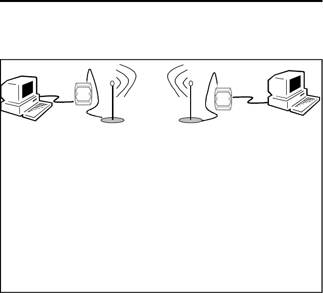
5.1 Peer-to-Peer Communication (Mode 1)
Figure 5.1 above depicts a basic serial full-duplex communication applica-
tion. In this type of application, both QTM-8524 modules are configured
for the same baud rate, frequency and channel.
RS-232 RS-232
QTM-8524 QTM-8524
QTM-8524 Configuration:
Interface: RS-232
Full Duplex
Synchronous
Master
Baudrate: 19200 bps MAX
Channel: 1
QTM-8524 Configuration:
Interface: RS-232
Full Duplex
Synchronous
Slave
Baudrate: 19200 bps MAX
Channel: 1
Figure 5.1-- Peer-to-Peer Communication
Quatech QTM-8524 Manual 41
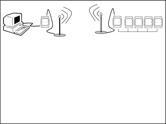
5.2 Interfacing with QTM-8000 Modules (Mode 1)
RS-232
RS-485
QTM-8524 QTM-8524
QTM-8524 Configuration:
Interface: RS-232
Full Duplex
Synchronous
Master
Baudrate: 19200 bps MAX
Channel: 1
QTM-8524 Configuration:
Interface: RS-485
Full Duplex
Synchronous
Slave
Baudrate: 19200 bps MAX
Channel: 1
Figure 5.2--QTM-8524 as part of a QTM-8000 Series
Data Acquisition and Signal Conditioning Network
QTM-8000 Series
Figure 5.2 above depicts QTM-8000 Series data acquisition and signal con-
ditioning modules integrated into a wireless network. The upstream QTM-
8524 connected to the PC should be set for RS-232 communication, the down-
stream QTM-8524 connected to the module network should be set for RS-
485. Both QTM-8524 modules must be configured for the same frequency,
channel and baud rate. The attached QTM-8000 Series I/O modules must
also be configured at that same baud rate. (Note that because of the speed
limitation imposed by the QTM-8524, communication over this network can
not exceed 19.2 kbps, even though QTM-8000 Series I/O Modules are them-
selves capable of speeds up to 115.2 kbps.) Up to 256 QTM-8000 I/O mod-
ules can be configured in a network using one pair of QTM-8524 modules.
42 Quatech QTM-8524 Manual
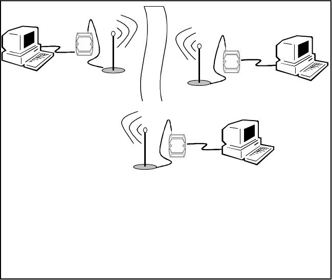
5.3 Multiple PC Communication (Mode 2)
RS-232
QTM-8524
RS-232
RS-232
QTM-8524
QTM-8524
QTM-8524 Configuration:
(All Modules)
Interface: RS-232
Half Duplex
Synchronous
Slave
Baudrate: 57600 bps MAX
Figure 5.3--QTM-8524 modules used to network multiple PCs
Figure 5.3 above depicts a basic multi-point application. In
this type of application, multiple QTM-8524 modules can
operate in a single wireless network. All modules must be
configured to Half-Duplex communication and must be set
in Slave State. Either RS-232 or RS-485 must be selected for
the entire network. All modules must also be configured to
operate at the same baud rate, channel and frequency. Note
that this mode cannot be used with QTM-8000 Series data
acquisition and signal conditioning modules.
Quatech QTM-8524 Manual 43
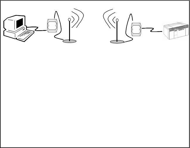
5.4 Asynchronous Communication (Mode 3)
RS-232 RS-232
QTM-8524 QTM-8524 PLC
QTM-8524 Configuration:
Interface: RS-232
Full Duplex
Asynchronous
Master
Baudrate: up to 14.4 kbps
QTM-8524 Configuration:
Interface: RS-232
Full Duplex
Asynchronous
Slave
Baudrate: up to 14.4 kbps
Figure 5.4--QTM-8524 modules in an asynchronous network
Figure 5.4 above depicts a basic asynchronous communica-
tion application. In this type of application, both QTM-8524
modules must be configured for Full-Duplex RS-232 commu-
nication, and they must operate at the same frequency. Baud
rate need not be the same for both modules, however it must
be less than 14.4 kbps. Note that asynchronous mode can not
be used with QTM-8000 Series I/O Modules.

44 Quatech QTM-8524 Manual
FCC Approvals
The QTM-8524 is approved pursuant to FCC Part 15.247 for intentional
spread spectrum radiators (47CFR15.247) while being used with the Quat-
ech supplied antennas (QTM-24ANT-SW and the QTM-24ANT-C). This
certification is applicable in the United States and all of its territories (Guam,
Samoa America, US Virgin Islands and Puerto Rico).
FCC ID: F4AQTM85242000
The QTM-8524 is approved pursuant to FCC Part 15 Subpart B limits for
unintentional radiators. Operation is subject to the following two condi-
tions: (1) this device may not cause interference, and (2) this device must
accept any interference, including interference that may cause undesired
operation of the device.
This equipment has been tested and found to comply with the limits for a
Class B digital device, pursuant to Part 15 of the FCC Rules. These limits are
designed to provide reasonable protection against harmful interference in a
residential installation. This equipment generates, uses and can radiate ra-
dio frequency energy and, if not installed and used in accordance with the
instructions, may cause harmful interference to radio communications. How-
ever, there is no guarantee that interference will not occur in a particular
installation. If this equipment does cause harmful interference to radio or
television reception, which can be determined by turning the equipment off
and on, the user is encouraged to try to correct the interference by one or more
of the following measures:
— Reorient or relocate the receiving antenna.
— Increase the separation between the equipment and receiver.
— Connect the equipment into an outlet on a circuit different from
that to which the receiver is connected.
— Consult the dealer or an experienced radio/TV technician for help.
Additional Antennas
Operation of this device with antennas that are not supplied by Quatech is
strictly prohibited under FCC regulations. Operation with antennas that
are non-compliant will void any warrantee whether explicit or implied.
6. Approvals
Quatech QTM-8524 Manual 45
DOC Approvals (Canada)
The QTM-8524 is approved for use in accordance with RSS-210 and RSS-
139. To prevent radio interference to the licensed service, this device is in-
tended to be operated indoors and away from windows to provide maxi-
mum shielding. Equipment (or its transmit antenna) that is installed out-
doors is subject to licensing.
CANXXXXXXXXXXX
Additional Antennas
This device has been designed for use with an antenna having a maximum
gain of 7.5dB. Antennas having higher gain is strictly prohibited per regula-
tions of Industry Canada. The required antenna impedance is 50 ohms.
Quatech Inc. will not be responsible or liable for systems or damage caused
by systems operated with unapproved antennas, and such operation will
void all warrantees whether explicit or implied.
46 Quatech QTM-8524 Manual
Cut this template out of the manual and use it as a guide for
drilling the holes needed to install your QTM-24ANT-SW wall-
mount antenna.
QTM-24ANT-SW Hole Template