Balluff LRP2000 Pass Through System User Manual testcov
BALLUFF inc Pass Through System testcov
UserManual.wiki
>
Balluff
>
LRP2000 User Manual
>
Manual Part1
Contents
1.
Manual Part1
2.
Manual Part2
Manual Part1
Navigation menu
Upload a User Manual
Namespaces
Wiki Guide
HTML
PDF
Info
Views
User Manual
Discussion / Help
Navigation


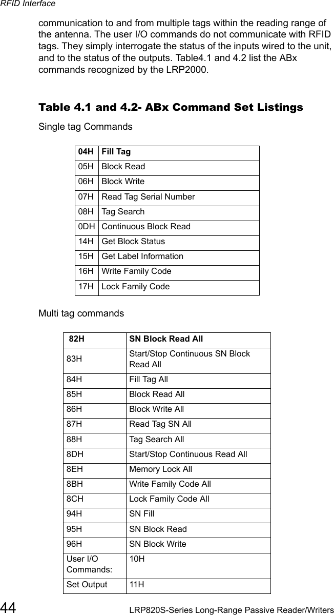
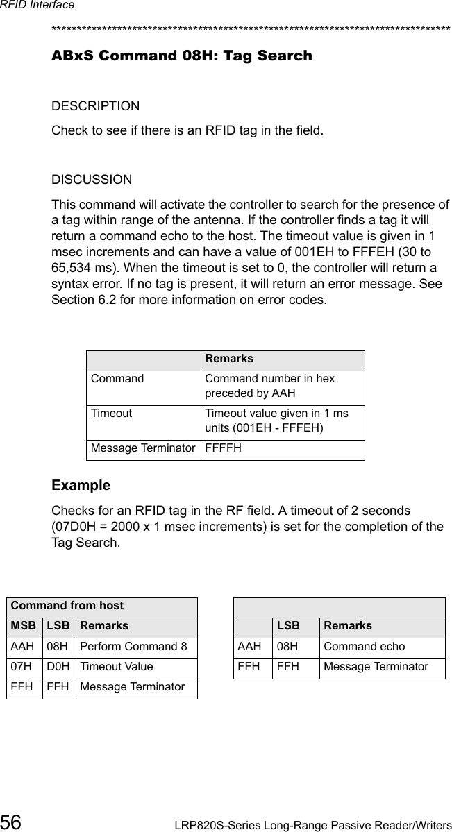
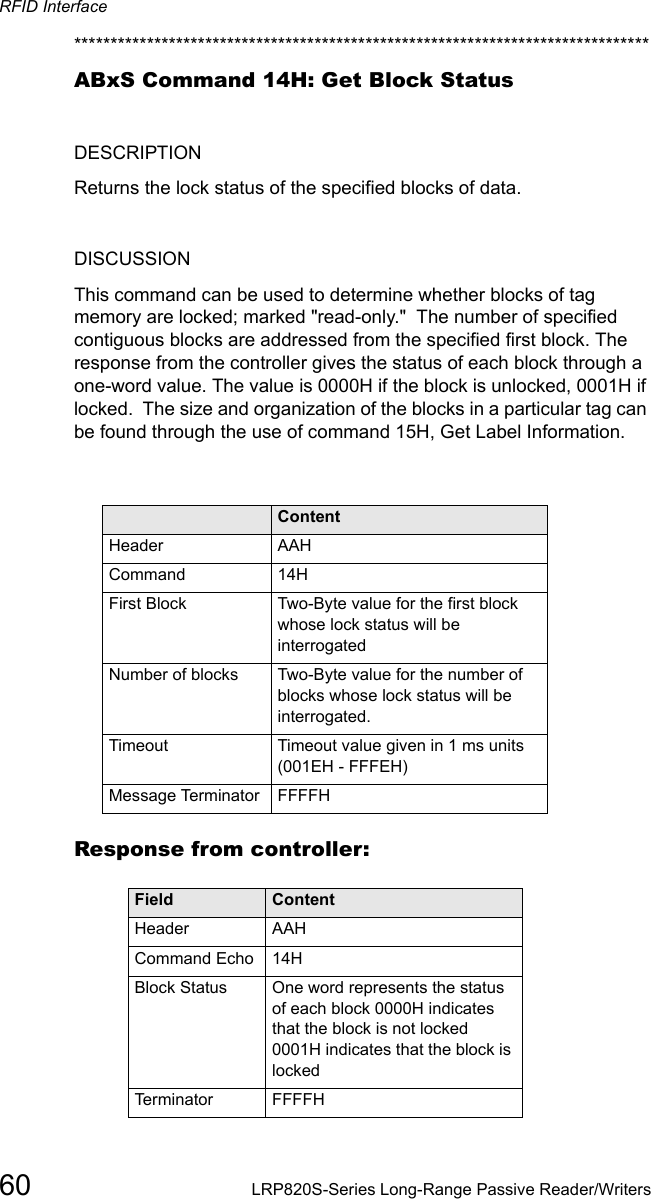
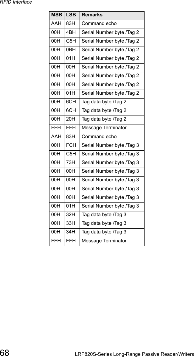
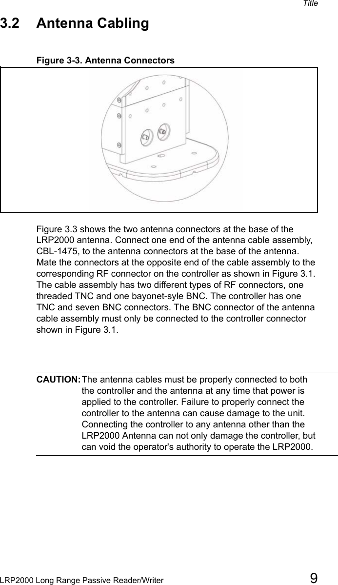
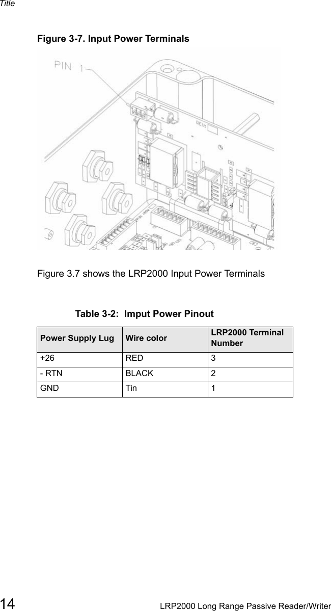
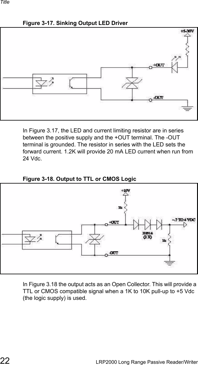
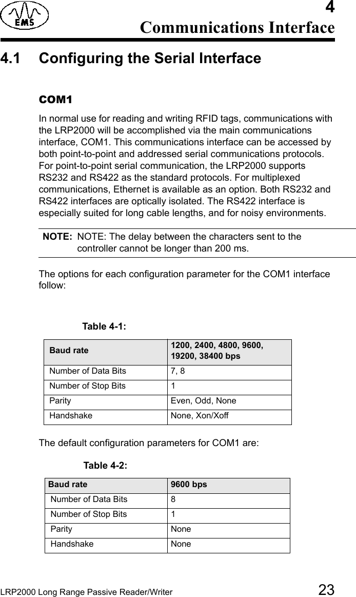
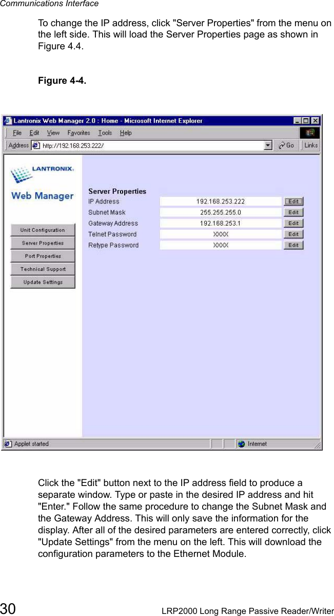
![LRP2000 Long Range Passive Reader/Writer 73Title3.1 Connectors and Wiring Figure 3-1. RF Connectors and Strain Reliefs Figure 3.1 shows the front connector panel with the four strain reliefs and the RF connectors. The controller ships with sealing caplugs in the strain reliefs, which should be left in any unused location for an environmental seal. The four strain reliefs will seal around cables ranging in diameter from 0.12 [3.0 mm] minimum to 0.32 [8.0mm] maximum. The wrench flats are [17mm].](https://usermanual.wiki/Balluff/LRP2000.Manual-Part1/User-Guide-341103-Page-13.png)
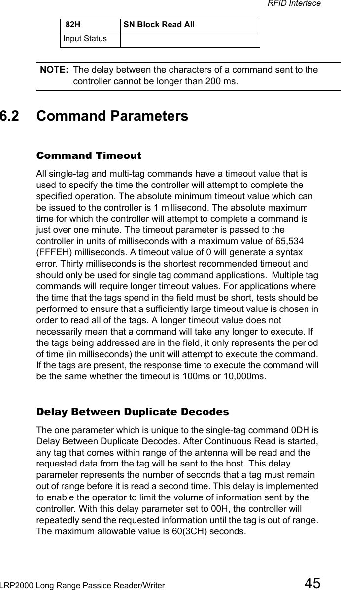
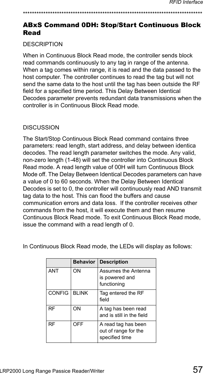
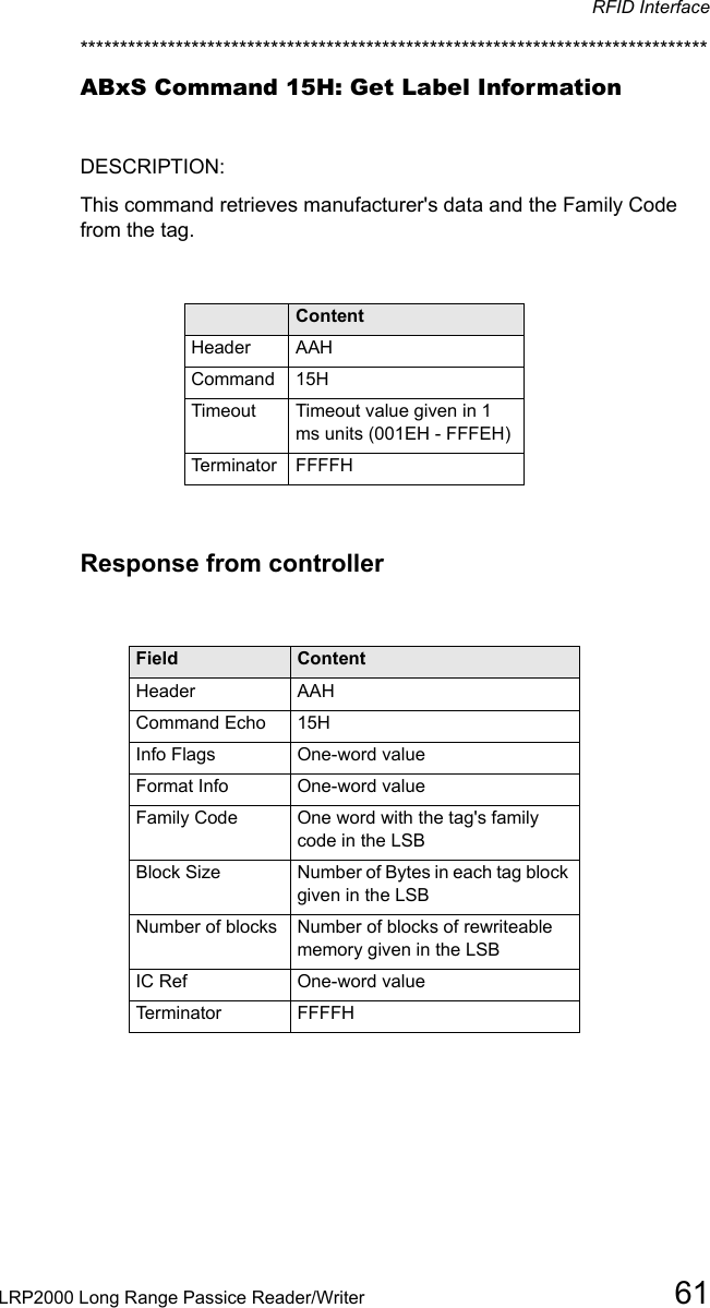
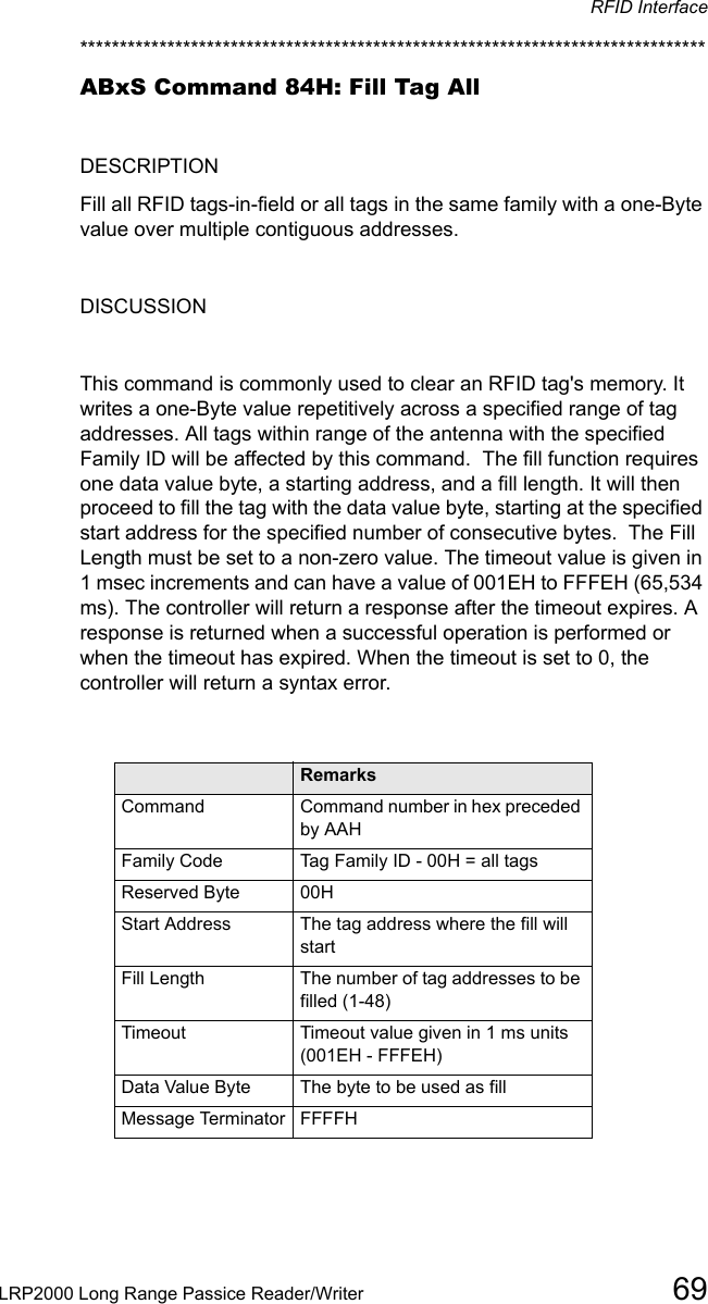
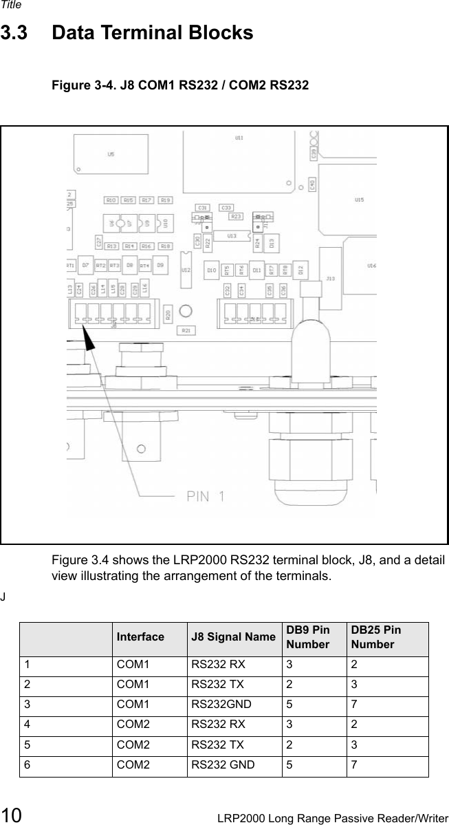
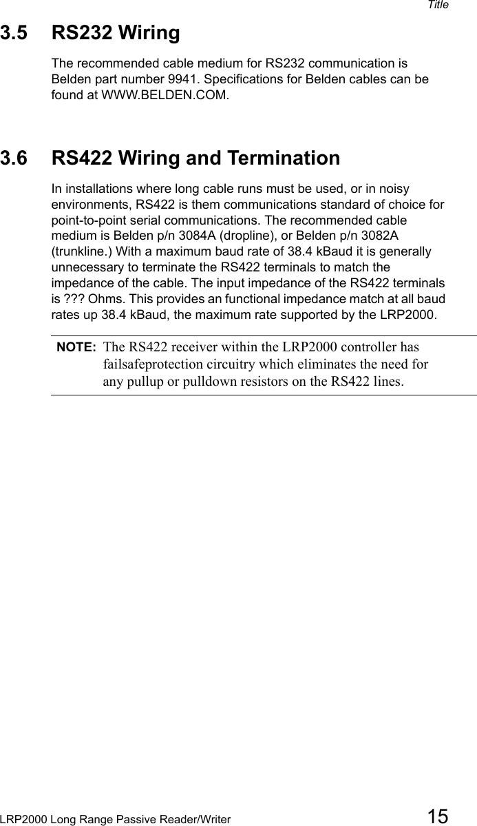
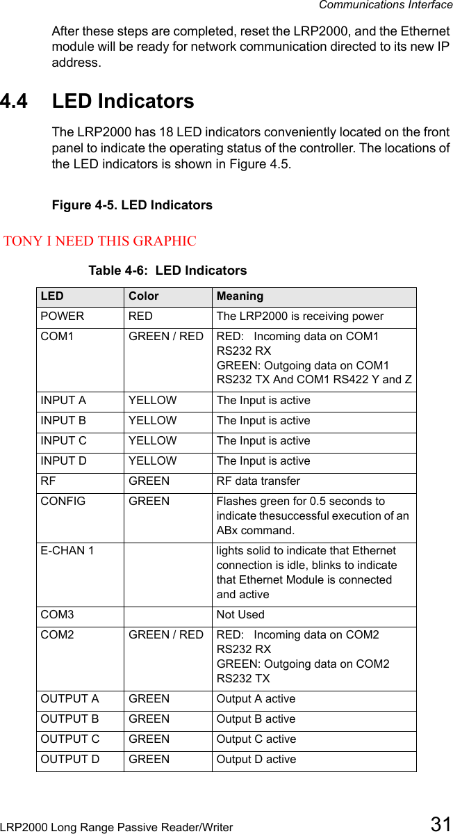
![Title8LRP2000 Long Range Passive Reader/WriterFigure 3-2. Internal ConnectorsFigure 3.2 shows an internal view of the controller. It details the locations of all internal terminal blocks needed for wiring the system. CAUTION:The controller contains ESD sensitive components. Always observe ESD-sensitive handling procedures when working inside the controller. Terminal BlocksThe controller is equipped with removable terminal blocks to aid wiring. The data terminals are all equipped with screw terminals which accept AWG 28 minimum to AWG 16 maximum diameter solid or stranded wire. The screws heads accept a 3/32 inch [2.0mm] or [2.5mm] screwdriver blade.](https://usermanual.wiki/Balluff/LRP2000.Manual-Part1/User-Guide-341103-Page-14.png)


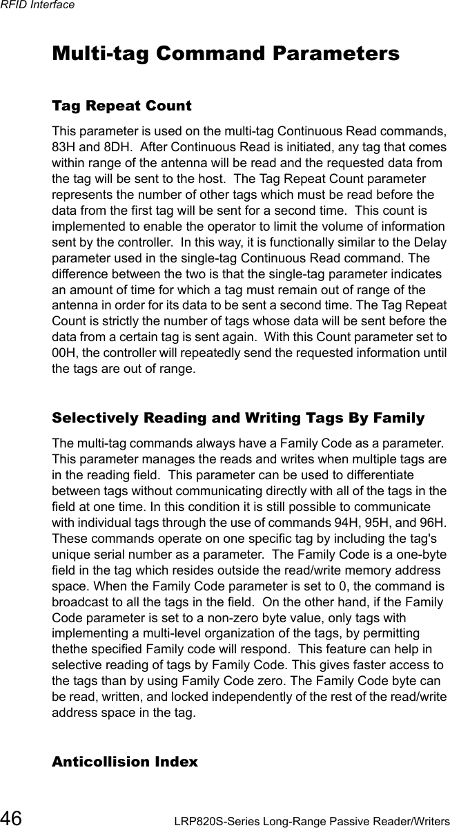
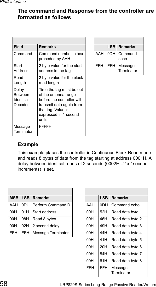
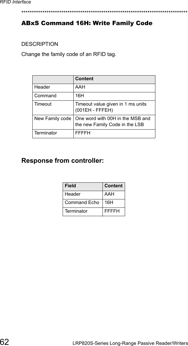
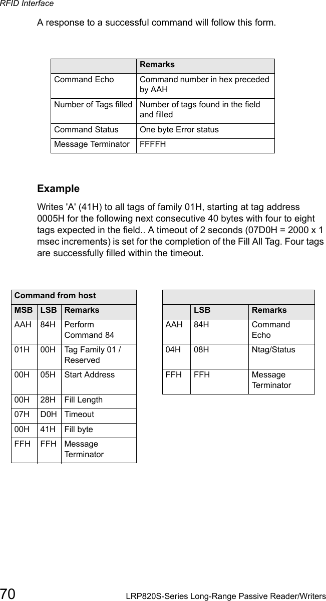
![Configuring the Menu36 LRP2000 Long Range Passive Reader/Writer DSP Program V0.5c, November 2002*******************************************[1] Set-up Operating Parameters[2] Download Main Program[3] Download DSP Program[4] Exit to Operating ModeEnter Selection:5.2 Set-up Operating ParametersTo change the operating parameters of the LRP2000, enter 1 at the initial menu. The following menu will be displayed, listing the current settings. The exact appearance of the menu display will dependon the settings you have made, and will be updated when you save your changes.Serial Port COM1: RS232, 9600, N, 8, 1, No handshake (DIP switches)Serial Port COM2: RS232, 9600, N, 8, 1, No handshakeOperating Mode: ABx StandardRF Communication: Fast Mode[1] Set COM1 Parameters[2] Set COM2 Parameters[3] Set Operating Mode[4] Set RF Communications[5] Restore Factory Defaults[6] Return to Main MenuEnter Selection: Enter the number of the sub-menu you wish to enter. When you have made your selection you will be prompted to save your changes to the non-volatile EEPROM. For the new settings to take effect, you must save your changes to the EEPROM and reset the LRP2000. If you do not save changes to the EEPROM, the new settings will be effective only until the LRP2000 is reset. The following sub-menus are presented here in their entirety. When operating, the menus will be presented one option at time, advancing as you enter selections. Some options shown are dependent on earlier selections.](https://usermanual.wiki/Balluff/LRP2000.Manual-Part1/User-Guide-341103-Page-42.png)
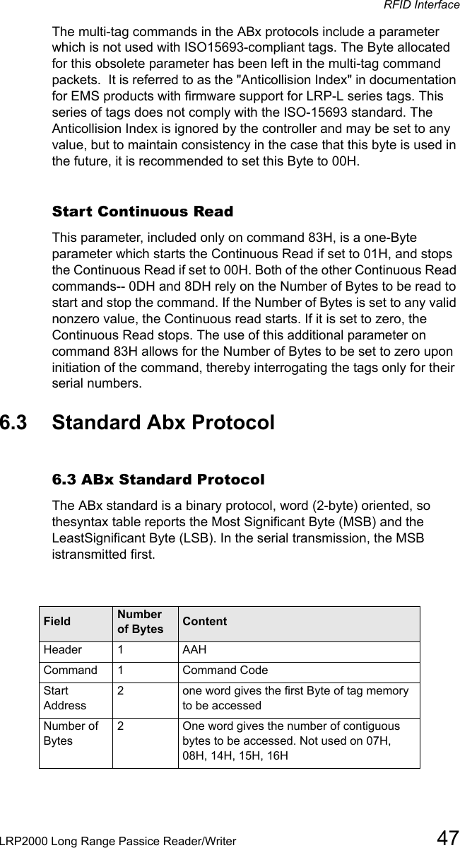
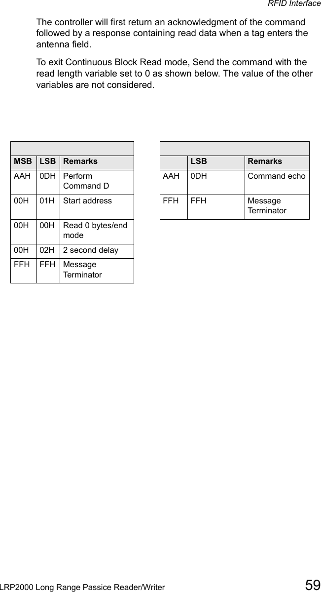
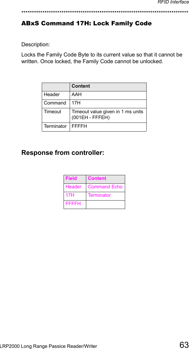
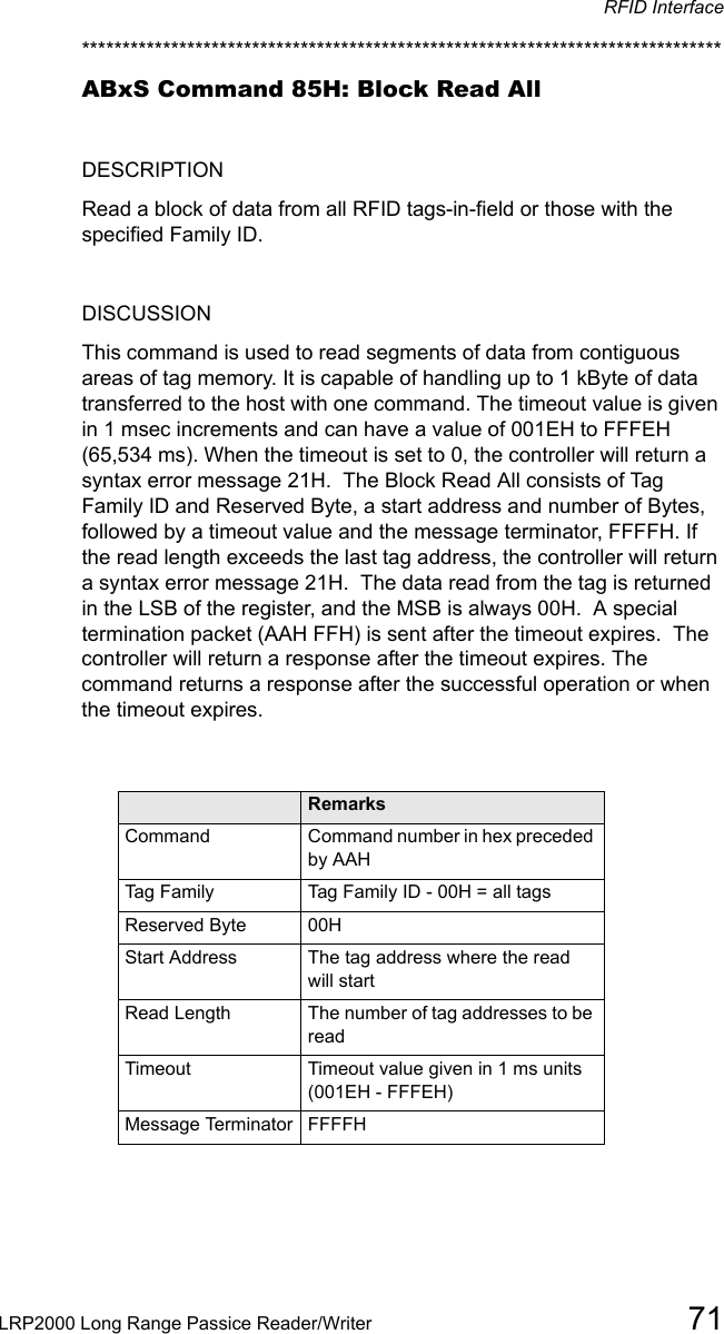
![Configuring the MenuLRP2000 Long Range Passive Reader/Writer 37Set COM1 ParametersSelecting 1 from the above menu will present the following display for the COM1 parameters. These settings are valid only if you are not using the DeviceNet Interfaces (e.g. DIP switch 4 is in the OFF position). Enter the appropriate number at each prompt. The default values are indicated by an asterisk (*). *** Set COM1 Parameters ***Baud Rate? [0] 1200 [1] 2400 [2] 4800 [3] 9600* [4] 19200 [5] 38400Data size? [0] 7 bit [1] 8 bit*Parity? [0] None* [1] Even [2] OddHandshake? [0] None* [1] Xon/XoffSave Changes to EEPROM? [0] No [1] YesSelecting 2 from the "[1] Set-up Operating Parameters" menu will bring up the following display for the COM2 parameters. Enter the appropriate number at each prompt. The default values are indicated by an asterisk.*** Set COM2 Parameters ***Baud Rate? [0] 1200 [1] 2400 [2] 4800 [3] 9600* [4] 19200Data size? [0] 7 bit [1] 8 bit*Parity? [0] None* [1] Even [2] OddHandshake? [0] None* [1] Xon/XoffSave Changes to EEPROM? [0] No [1] YesSet Operating ModeThe "[3] Set Operating Mode" menu allows you to choose the ABx command protocol the LRP2000 will use, or configure it to automatically enter Continuous Read Mode upon start-up.*** Set Operating Mode ***Command Protocol? [0] ABx Standard* [1] ABx Fast [2] ABx ASCIIChecksum? [0] Disabled* [1] EnabledPower up in Continuous Read Mode? [0] NO [1] Single](https://usermanual.wiki/Balluff/LRP2000.Manual-Part1/User-Guide-341103-Page-43.png)
![Configuring the Menu38 LRP2000 Long Range Passive Reader/WriterTag [2] Multiple TagStart Address (0 to 47)Length (1 to 48)Delay Between Duplicate Decodes (0 to 60)Raw Read Response? [0] NO [1] CR terminate [2] CR/LF terminateSave Changes to EEPROM? [0] No [1] YesCommand Protocol?The LRP2000 offers three modes for the transfer of data and commands. ABxStandard (ABxS) uses only the LSB for tag data while ABx Fast (ABxF) will use both the MSB and the LSB for the passing of data. ABx ASCII (ABxA)mode permits RFID operations using seven bit data packets in the form of printable ASCII characters.ChecksumABx Fast and ABx ASCII also permits you to include a checksum in the command. To use a checksum value with the ABx commands, you must enable the checksum option. It is recommended that you enable the checksum option.Power up in Continuous Read ModeYou also have the option of setting the LRP2000 to start-up in Continuous Read Mode. When you have configured the LRP2000 to function in this manner,you do not issue commands to the LRP2000. It will, upon start-up, enter directly into a Continuous Read Mode. Since this bypasses the normal command parameters, you must specify the Continuous Read Mode parameters. The LRP2000 will respond to other commands and resume Continuous Read Mode when completed. If you are using your LRP2000 in this mode, you must choose if you want the LRP2000 to read a single tag or read multiple tags within the field. To exit Continuous Read Mode you must either re-enter the configuration menu and select NO from the Power up in Continuous Read Mode option, or issue a Continuous Read command from the host with a read length of 0 as described in Chapter 6, RFID Interface.Start Address (0 to 111)Enter the tag address where you want the read to begin.Length (1 to 112) 112Enter the length of the read you wish the LRP2000 to perform. Make certain that the length value does not exceed the number of possible addresses following the starting tag address. Entering a read length of 0 will disable Continuous Read Mode.](https://usermanual.wiki/Balluff/LRP2000.Manual-Part1/User-Guide-341103-Page-44.png)
![Configuring the MenuLRP2000 Long Range Passive Reader/Writer 39Delay Between Identical Decodes (0-60)The Delay Between Identical Decodes parameters can have a value of 0 to 60 seconds. When the Delay Between Identical Decodes is set to 0, the LRP2000 will continuously read AND transmit tag data to the host. This can flood the buffers and cause communication errors and data loss.Raw Read ResponseIf you have selected ABx Fast or ABx ASCII, you have the option of stripping the command protocol from the data and adding a terminator to separate the data packets. You can choose a CR (0DH) or CR/LF (0DH, 0AH) to terminate the data.Set RF CommunicationThe LRP2000 should be configured with the default (0) Fast Mode.*** Set RF Communication ***RF Communication? [0] Fast Mode* [1] Standard Mode 0Save Changes to EEPROM? [0] No [1] YesRestore Factory DefaultsIt is often helpful during troubleshooting to restore the LRP2000 to known default values. To do so, select 5 from the "[1] Set-up Operating Parameters" menu .*** Restore Factory Defaults ***Restore Factory Default? [0] No [1] YesThe restored defaults will be saved to the EEPROM. The communication defaults can also be restored by placing the main board DIP switch number 5 in the ON position and then restarting the LRP2000. After you have saved any changes, you must re-initialize the LRP2000 with switch 5 in the OFF position. Return to Main MenuWhen you have completed your configuration, entering 6 will return you to the initial menu. Unsaved changes will be effective until the LRP2000 is reset. Saved changes will be loaded automatically the next time the LRP2000 is reset, or upon selection of "[4] Exit to Operating Mode" from the main menu.](https://usermanual.wiki/Balluff/LRP2000.Manual-Part1/User-Guide-341103-Page-45.png)