Balluff LRP75 RFID Reader/Writer User Manual LRP75
BALLUFF inc RFID Reader/Writer LRP75
UserManual.wiki
>
Balluff
>
LRP75 User Manual
>
Manual R5
Contents
1.
Manual R5
2.
Manual R2
Manual R5
Navigation menu
Upload a User Manual
Namespaces
Wiki Guide
HTML
PDF
Info
Views
User Manual
Discussion / Help
Navigation
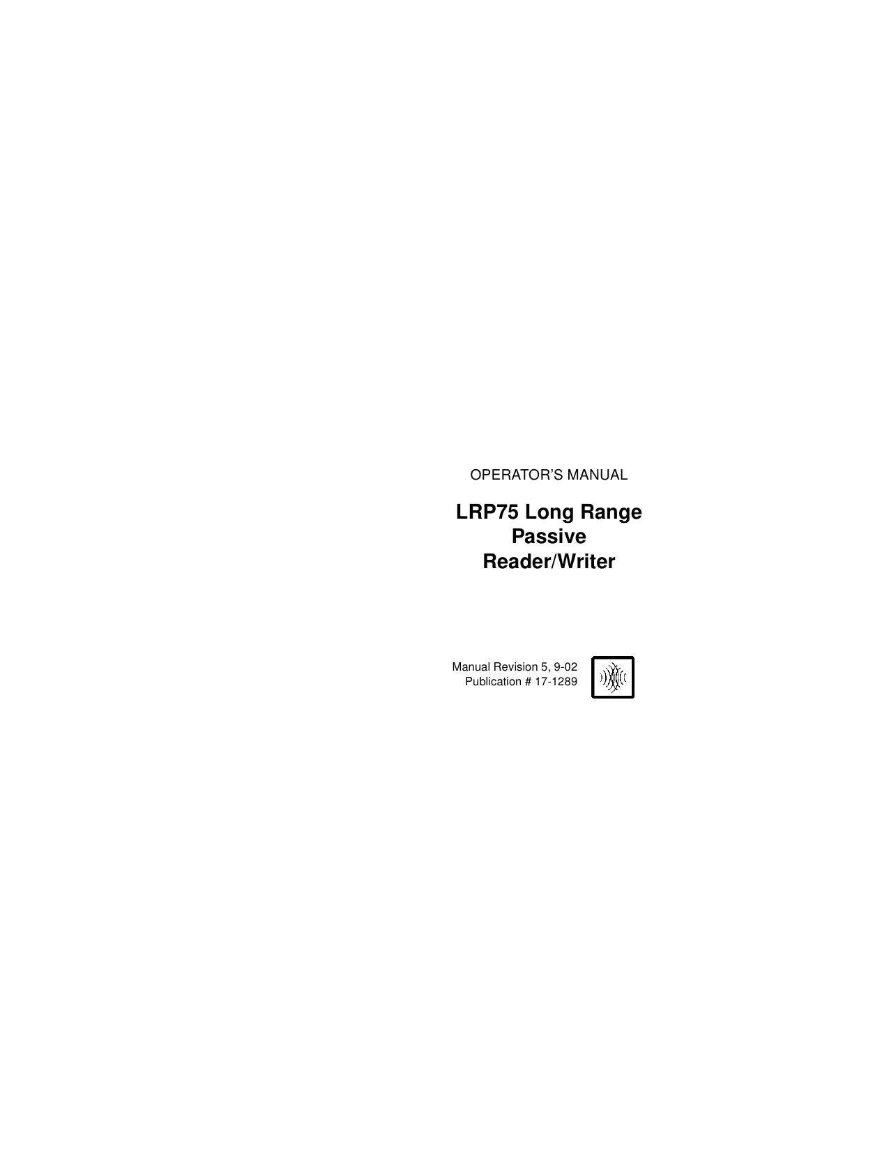
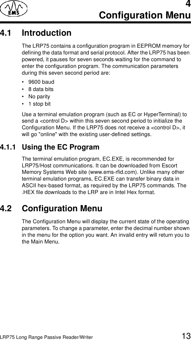
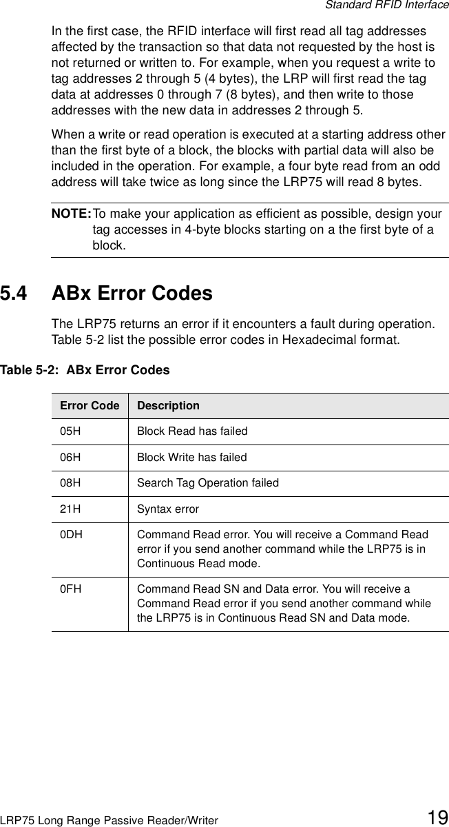
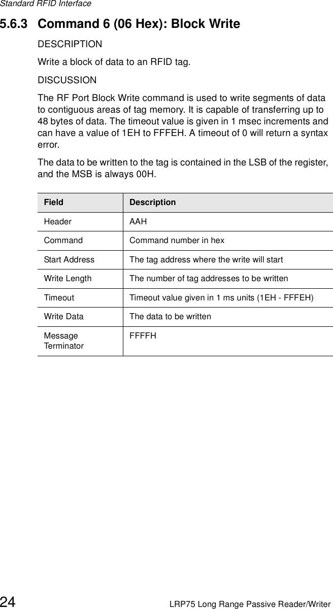
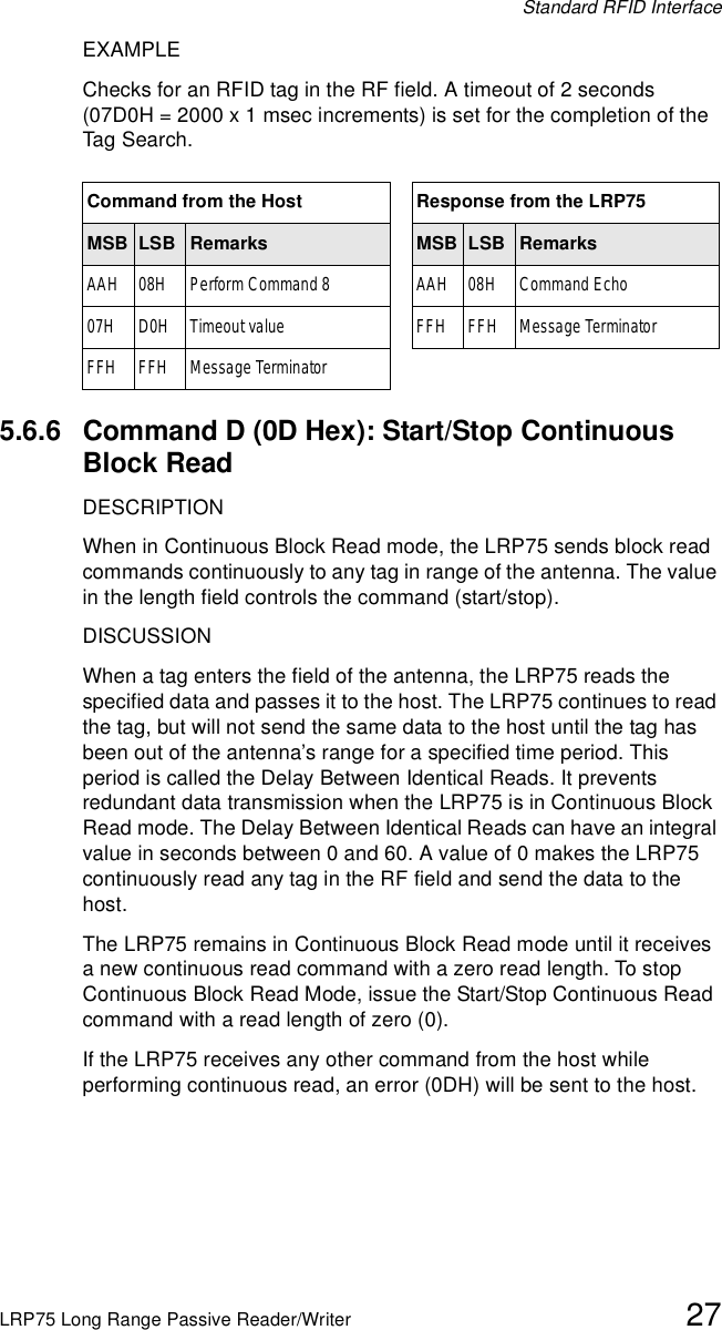
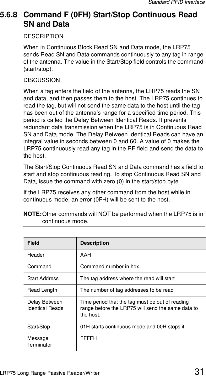
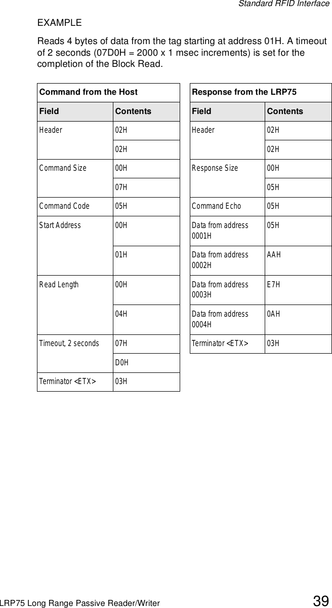
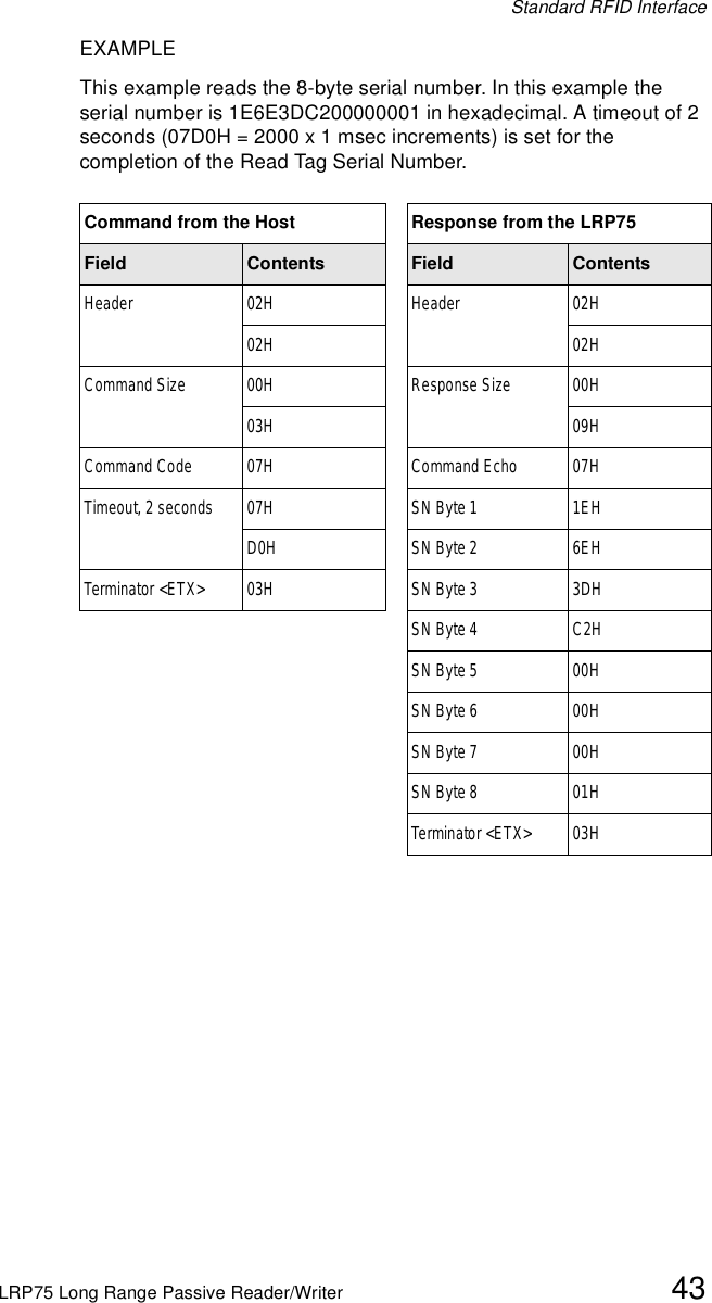
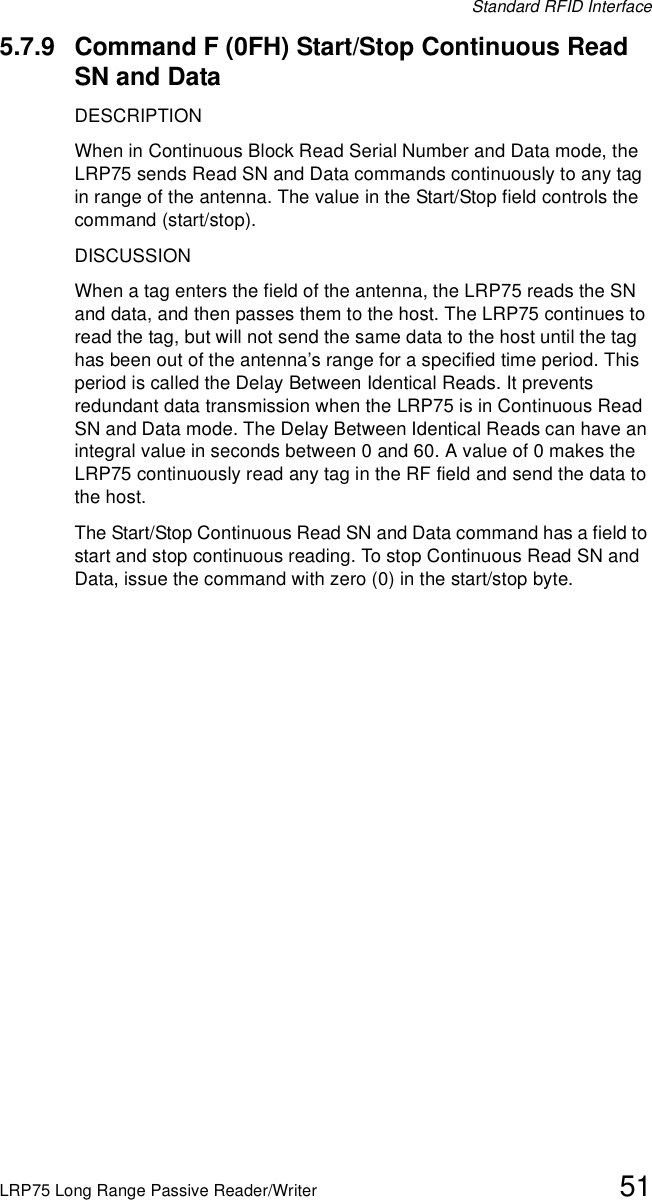
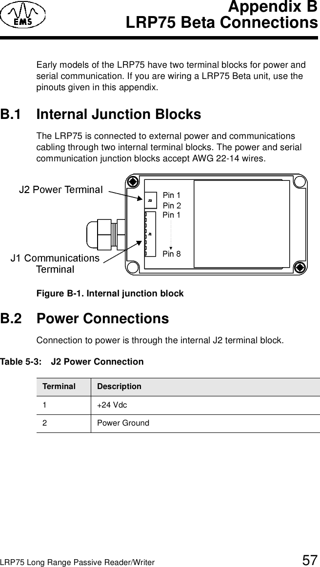
![Configuration Menu14 LRP75 Long Range Passive Reader/WriterThe Main Board Configuration menu displays the current main board software version number together with the RFID firmware version.******** LRP75/76 Standard Program V1.3E ********RF module:4.01JSerial Port COM1:RS232, 9600, N, 8, 1 No HandshakeOperating Mode:ABx StandardTag Type: Phillips I-CODE 1[1] Set COM1 Parameters[2] Set Operating Mode[3] Set Tag Type[4] Restore Factory Defaults[5] Download New Program[6] Download RFID Firmware[7] Exit to Operating ModeEnter Selection:4.2.1 Set COM1 ParametersThe Set COM1 Parameters menu is given below. *** Set COM1 Parameters **Operating mode? [0] RS232 [1] RS422Baud Rate? [0] 1200 [1] 2400 [2] 4800 [3] 9600 [4] 19200Data size? [0] 7bit [1] 8bitParity? [0] None [1] Even [2] OddHandshake [0] None [1] Xon/Xoff Save Changes to EEPROM? [0] No [1] YesEnter the number corresponding to the parameter you wish to enable. 4.2.2 Set Operating ModeThe Set Operating Mode menu is given below. *** Set Operating Mode ***Commands Protocol? [0] ABx Standard [1] ABx Fast Checksum? [0] Disabled [1] Enabled Power up performing Continuous Read?[0] NO[1] Continuous Block Read (0DH) active[2] Continuous Read SN and Data (0FH) active-> 1Start Address (0 to 47) 0Length (1 to 48) 48Delay Between Duplicate Decodes (0 to 60) 1Raw Read Response? [0] NO [1] CR terminate [2] CR/LF terminate 2Save Changes to EEPROM? [0] No [1] Yes](https://usermanual.wiki/Balluff/LRP75.Manual-R5/User-Guide-283027-Page-18.png)
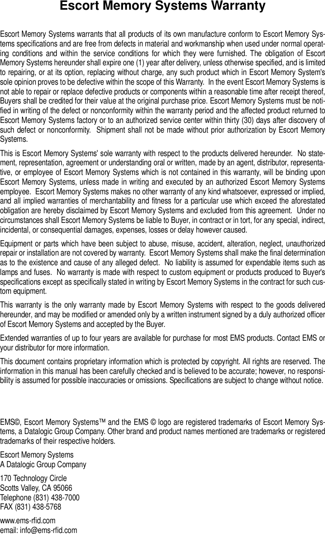
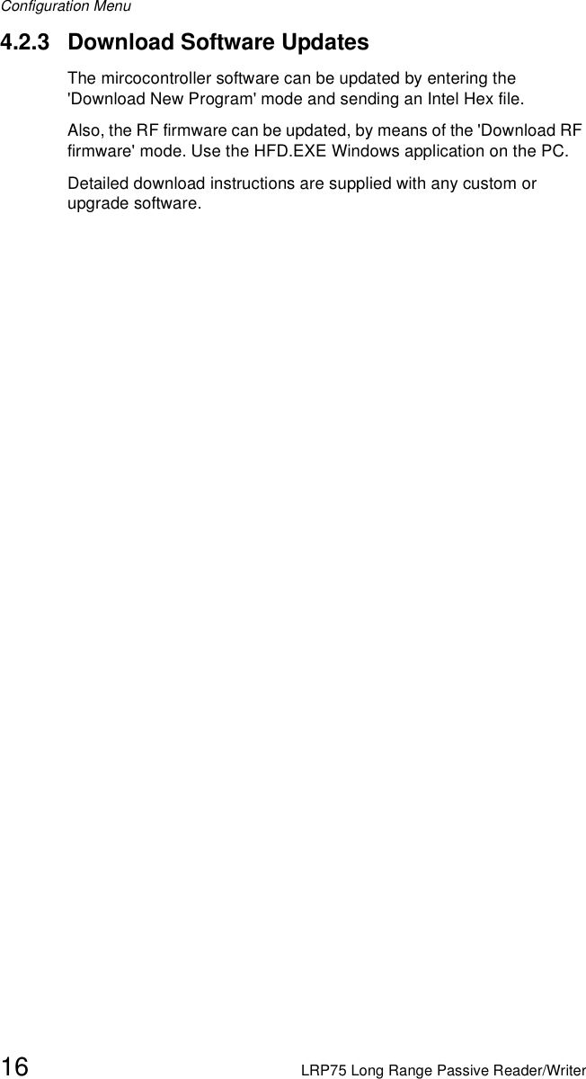
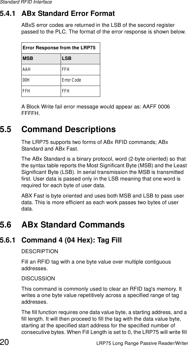
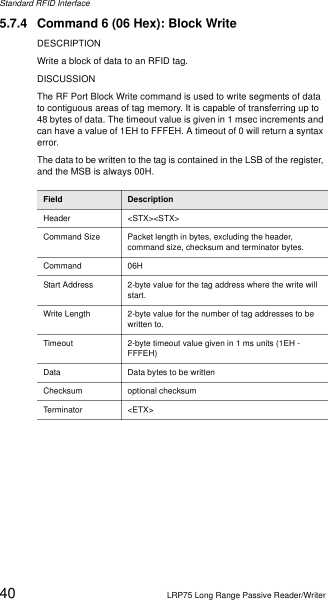
![Configuration MenuLRP75 Long Range Passive Reader/Writer 15The LRP75 supports ABx Standard and ABx Fast RFID command protocols. Select your command protocol from this menu. If you select ABx fast, you can select an optional checksum. For data delivery verification to the host, it is recommended to have the checksum enabled.You can also select from three Run Mode types. The options are:[0] NOLRP75 will wait for an ABx command after reset. If you choose 0 (NO), then the LRP75 configuration is complete and you are given the option to save the settings.[1] Continuous Block Read (0DH) activeAfter reset, the LRP75 will be in Continuous Block Read Mode just as if you had issued a Continuous Block Read (0DH) to the LRP75. You must enter the tag start address, read length, and the delay between identical decodes values.[2] Continuous Read SN and Data (0FH) activeAfter reset, the LRP75 will be performing Continuous Read SN Data. This is the same as if the 0FH command had been issued to the LRP75. You must enter the tag start address, read length, and the delay between identical decodes values.Raw Read ResponseIt is possible to set the LRP75 to only send raw tag data to the host. The raw read data does not contain a header, length, command number, or terminator. If the data on the tag is all printable ASCII, then the entire packet can be printed on any terminal emulator or EC.To receive a raw read response, the LRP75 must be set to use ABx Fast, and to start in Continuous Block Read Run Mode.Raw Read Response? [0] NO [1] CR terminate [2] CR/LF terminateIf you choose the raw response option 0 (NO), then standard ABx response packets are returned when a tag is read. If you choose option 1 or 2 (CR or CR/LF terminate), then the entire header and footer are removed from the response. If you choose CR or CR/LF, then a carriage return (0DH) or carriage return line feed (0DH, 0AH) is append to the raw string of data from the tag. There is no header, length, command echo, footer, or checksum in this response string. Raw Read Response does not allow any delivery or data verification.](https://usermanual.wiki/Balluff/LRP75.Manual-R5/User-Guide-283027-Page-19.png)
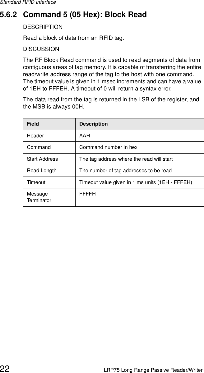
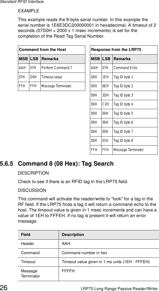
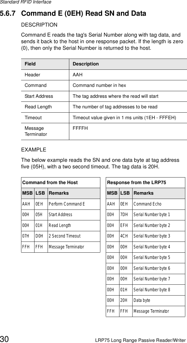
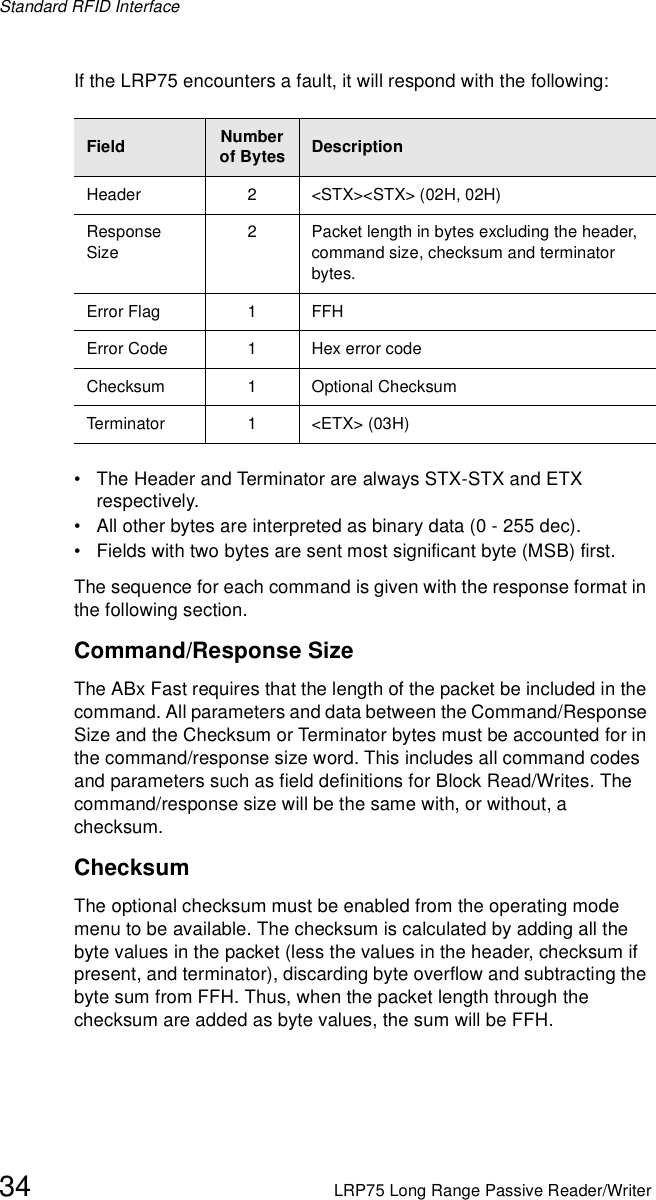
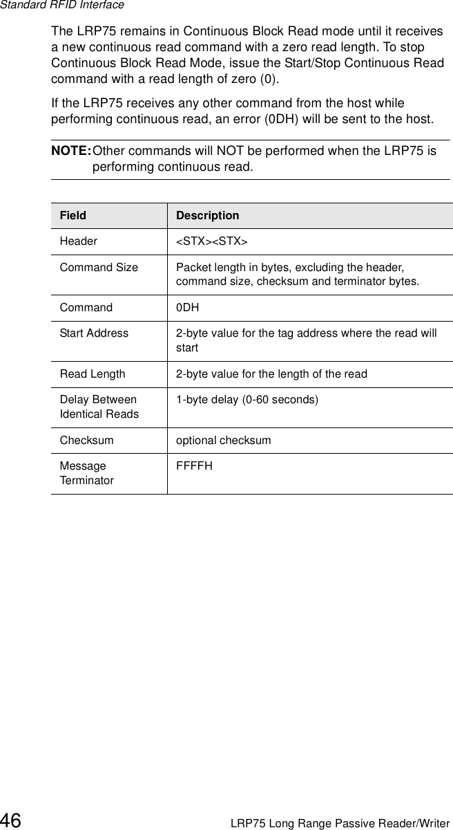
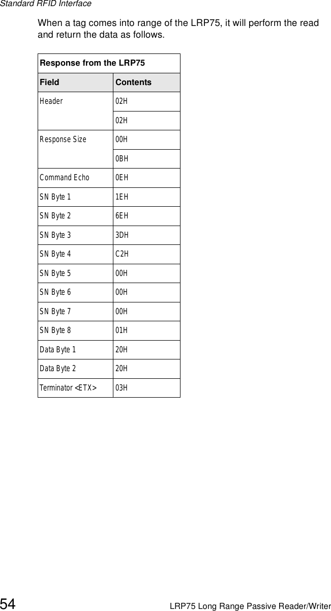
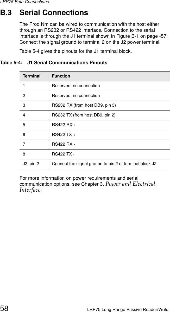

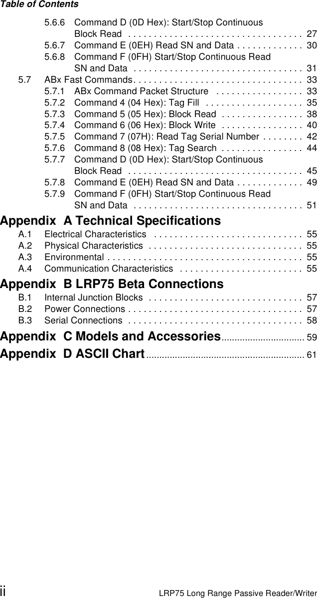
![ASCII Chart62 LRP75 Long Range Passive Reader/Writer064 40 @ 096 60 ‘065 41 A 097 61 a066 42 B 098 62 b067 43 C 099 63 c068 44 D 100 64 d069 45 E 101 65 e070 46 F 102 66 f071 47 G 103 67 g072 48 H 104 68 h073 49 I 105 69 i074 4A J 106 6A j075 4B K 107 6B k076 4C L 108 6C l077 4D M 109 6D m0784E N 1106E n079 4F O 111 6F o08050 P 11270 p08151 Q 11371 q08252 R 11472 r08353 S 11573 s08454 T 11674 t08555 U 11775 u08656 V 11876 v08757 W 11977 w088 58 X 120 78 x089 59 Y 121 79 y090 5A Z 122 7A z091 5B [ 123 7B {092 5C \ 124 7C |093 5D ] 125 7D }094 5E ^ 126 7E ~095 5F _ 127 7F DELDecimal Hex Character Decimal Hex Character](https://usermanual.wiki/Balluff/LRP75.Manual-R5/User-Guide-283027-Page-66.png)