Balluff M56HSAREI0100 Passive RFID Reader / Writer User Manual HS500E Operator s Manual
BALLUFF inc Passive RFID Reader / Writer HS500E Operator s Manual
UserManual.wiki
>
Balluff
>
M56HSAREI0100 User Manual
Users Manual
Navigation menu
Upload a User Manual
Namespaces
Wiki Guide
HTML
PDF
Info
Views
User Manual
Discussion / Help
Navigation

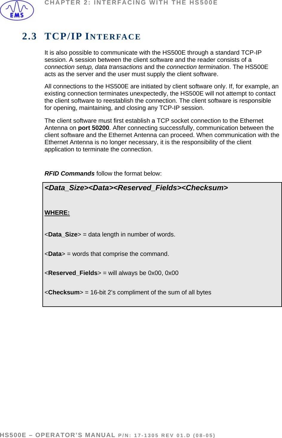
![CHAPTER 2: INTERFACING WITH THE HS500E Assign a name to the new device. In the example below, the device has been named EMS. Configure the IP Address to match the IP Address of the HS500E. Match the Connection Parameters to the image below. After clicking the OK button, there will be predefined tags containing the specified I/O Information. Predefined Tags INPUT EMS:I.Data [0] = Consume Data Sequence Number Handshake EMS:I.Data [1] = Produce Data Sequence Number EMS:I.Data [2] = Node 1 Serial Produce Data Size EMS:I.Data [3-202] = Node 1 Serial Produce Data OUTPUT EMS:O.Data [0] = Produce Data Sequence Number Handshake EMS:O.Data [1] = Consume Data Sequence Number EMS:O.Data [2] = Node 1 Serial Consume Data Size EMS:O.Data [3-202] = Node 1 Serial Consume Data HS500E – OPERATOR’S MANUAL P/N: 17-1305 REV 01.D (08-05) PAGE 15 OF 51](https://usermanual.wiki/Balluff/M56HSAREI0100/User-Guide-580816-Page-15.png)
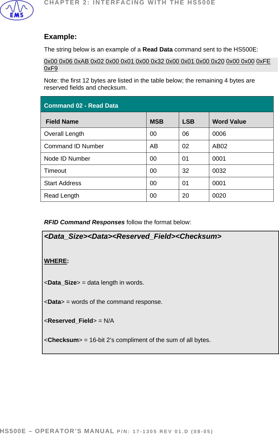
![CHAPTER 2: INTERFACING WITH THE HS500E EMS_Write1 [0] = (2) the counter is copied here by the HS500E to ACK EMS_Write1 [1] = (3) the HS500E increments this counter to signal a response is available EMS_Write1 [2] = Data Size EMS_Write1 [3-202] = Data OUTPUT (where commands are retrieved by the HS500E) EMS_Read1 [0] = (4) the counter is copied here by PLC to ACK the response EMS_Read1 [1] = (1) PLC increments this counter after copying a command EMS_Read1 [2] = Data Size EMS_Read1 [3-202] = Data INPUT (where responses are written by the HS500E) 2.6.1 Handshaking To ensure that messages to and from an HF-Series Controller are properly delivered and received, a handshaking mechanism has been implemented that uses a pair of dedicated words in the exchange. The first 2 words in each tag are dedicated to handshaking. When new information is generated, the producing device (data producer) increments a counter, and the consuming device (data consumer) copies that same counter value to another memory location to signal that the information has been processed. 2.6.2 Handshaking Example The example below gives a simplified explanation of the handshaking scheme. 1. The PLC copies the command to the Output area and then increments the counter in EMS_READ1 [1] 2. The counter in EMS_READ1 [1] is copied by the HS500E to EMS_WRITE1 [0] which acknowledges that it received of the command. HS500E – OPERATOR’S MANUAL P/N: 17-1305 REV 01.D (08-05) PAGE 29 OF 51](https://usermanual.wiki/Balluff/M56HSAREI0100/User-Guide-580816-Page-29.png)
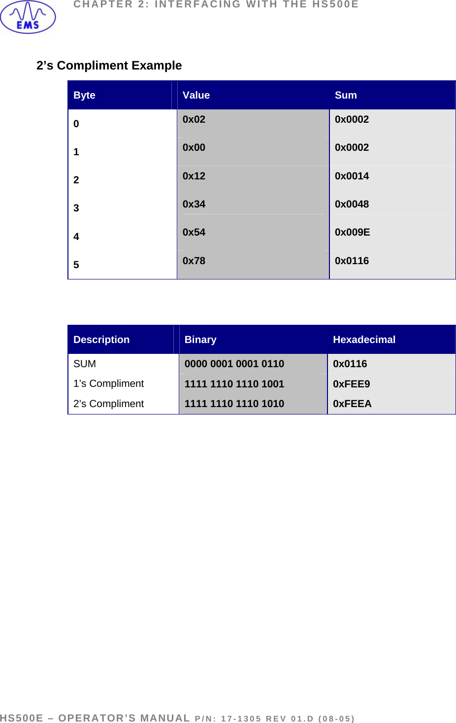
![CHAPTER 2: INTERFACING WITH THE HS500E 3. The HS500E places the response in the write area and then increments the counter in EMS_WRITE1 [1] which signals that there is new information for the PLC (the RFID controller’s command response). 4. After the PLC has processed the response information, it copies the counter found in EMS_WRITE1 [1] to the read area in EMS_READ1 [0] which signals (to the HS500E) that the PLC has read the response data. HS500E – OPERATOR’S MANUAL P/N: 17-1305 REV 01.D (08-05) PAGE 30 OF 51](https://usermanual.wiki/Balluff/M56HSAREI0100/User-Guide-580816-Page-30.png)
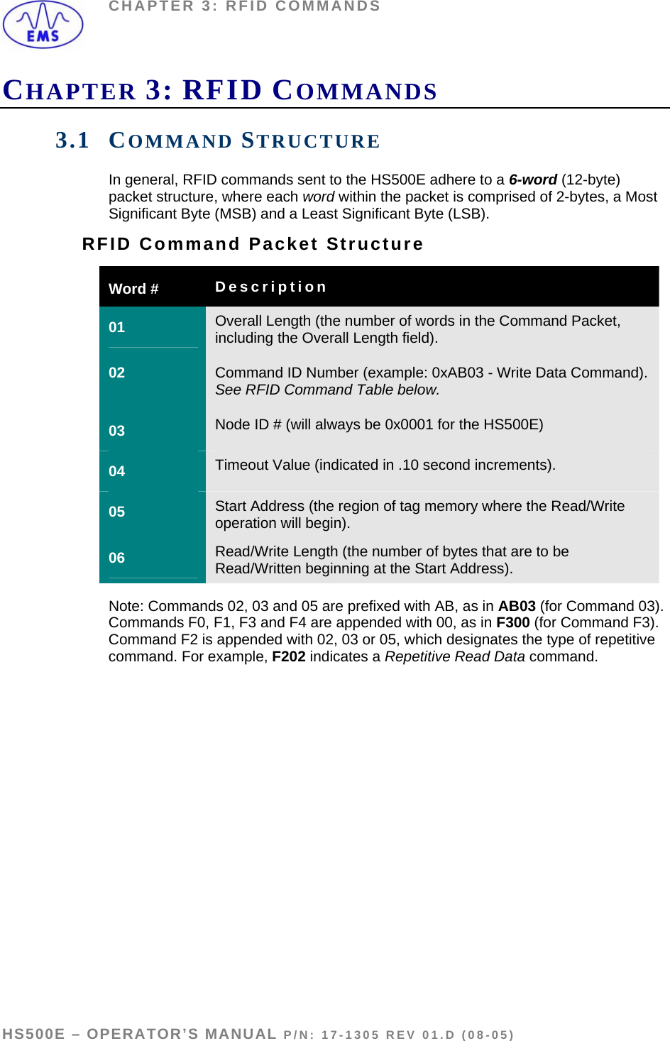
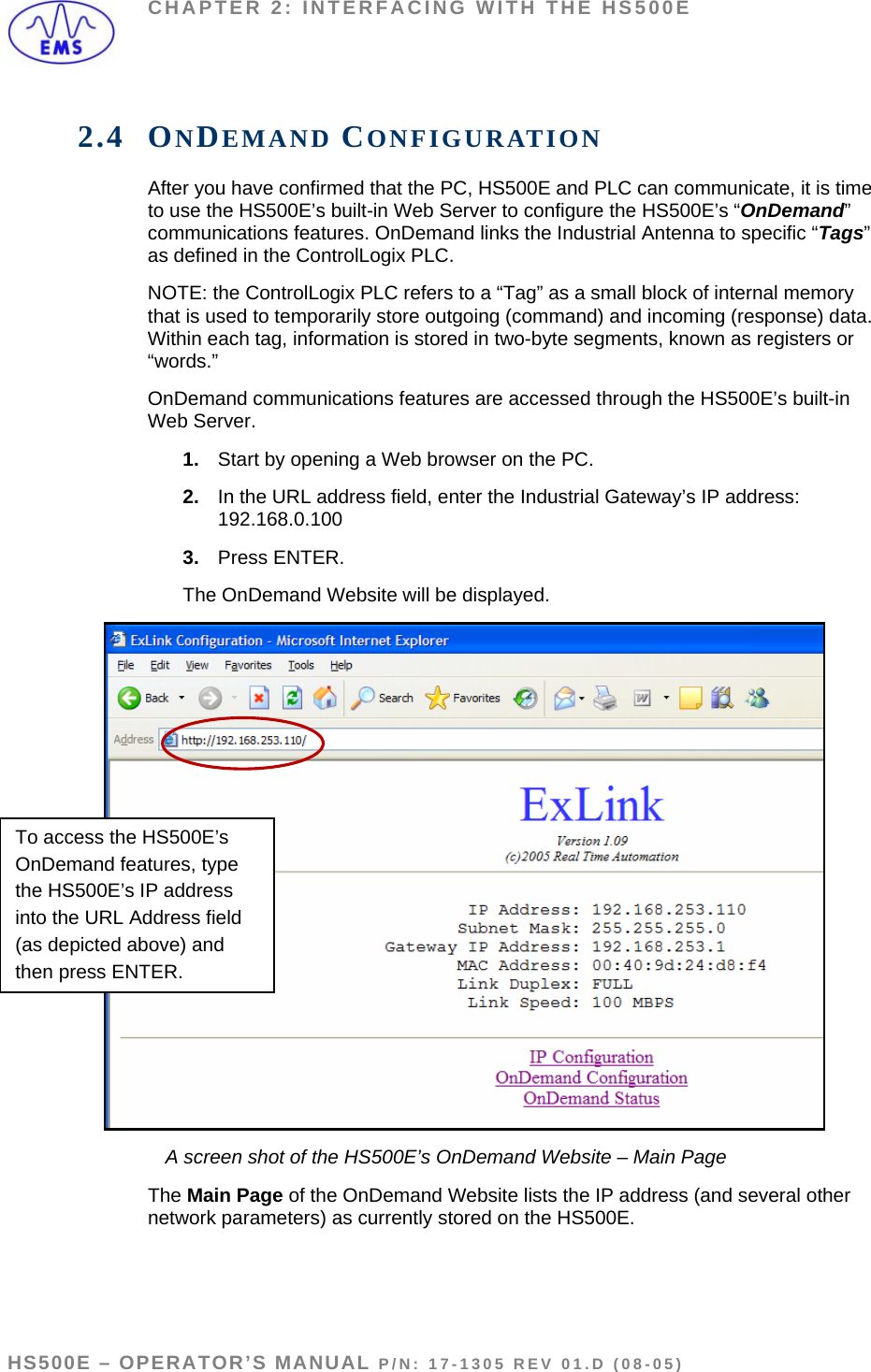
![CHAPTER 3: RFID COMMANDS COMMAND 02: READ DATA DESCRIPTION Command 02 instructs the Ethernet Antenna to Read Data from a contiguous area of an RFID tag’s memory. DISCUSSION The Read Data command is used to read a specified number of bytes from contiguous areas of tag memory. This command consists of the Overall Length (OAL), the Command ID Number, a Timeout Value, a Start Address and Read Length. The minimum Read Length is 1 byte. If the Read Length extends beyond the last tag address, an error will occur. The Timeout Value is measured in .10 second increments and can have a minimum value of 1 (0x0001). Note that tag address 0x0000 contains a 1-byte Battery Counter Value. To retrieve this value, the Start Address should be set to 0x0000. EXAMPLE In the example below, the Ethernet Antenna will read 4-bytes from the tag beginning at the address 0x0001. The Timeout value is set for 5 seconds (0x0032 = 50 decimal, 50 x .10 = 5 seconds) for the completion of this command. Command from Host Command 02: Read Data – Command Structure Field Name MSB LSB Word Value Overall Length (in words) 00 06 0006 [0xAB] + Command ID Number AB 02 AB02 MSB = reserved, always 0x00. LSB = Node ID # (always 0x01 for the HS500E) 00 01 0001 Timeout Value (in .10 sec increments) 00 32 0032 Start Address 00 01 0001 Read Length 00 04 0004 HS500E – OPERATOR’S MANUAL P/N: 17-1305 REV 01.D (08-05) PAGE 34 OF 51](https://usermanual.wiki/Balluff/M56HSAREI0100/User-Guide-580816-Page-34.png)

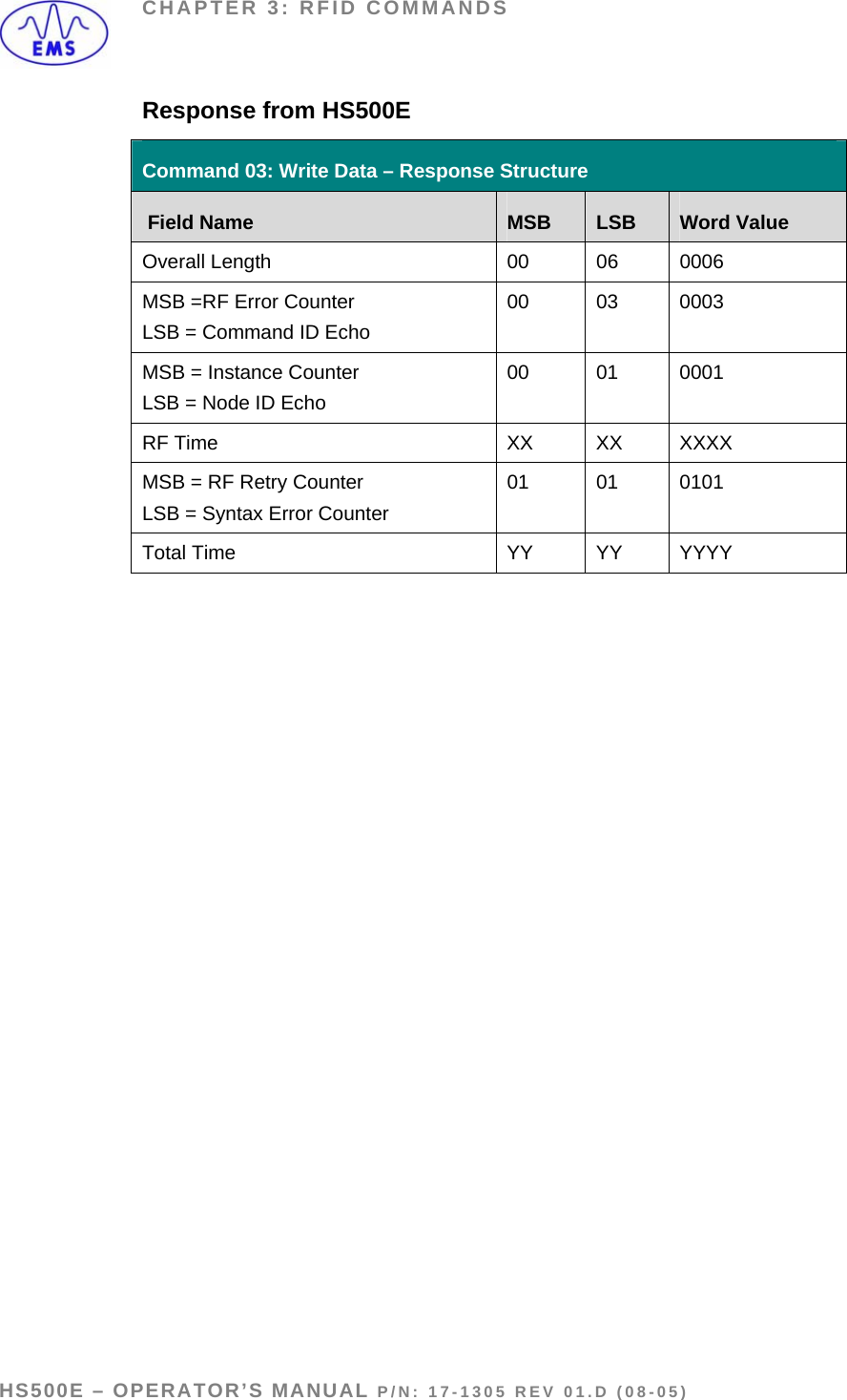
![CHAPTER 3: RFID COMMANDS COMMAND 03: WRITE DATA DESCRIPTION Command 03 instructs the Ethernet Antenna to Write Data to contiguous areas of an RFID tag’s memory. DISCUSSION This command is used to write segments of data to contiguous addresses of tag memory. The Write Data command consists of an Overall Length, the Command ID, a Timeout Value, Start Address and Write Length, and the Data Byte Value(s) to be written to the tag. When an odd number of bytes are to be written, the LSB of the final Data Byte Value word must contain 0x00. • Start Address: 0x0001 = Starts writing to the first accessible byte of tag memory (byte 0x0000 is reserved for the Battery Counter byte). • Write Length: 0x0001 = Shortest possible Write Length. If the Write Length is set to 0, or extends past the last byte address of the tag, the unit will generate an error code. EXAMPLE In this example, the Write Data command will instruct the HS500E to write the specified 8 bytes to the tag beginning at the Start Address of 0x0001. A Timeout value of 5 seconds is set for the completion of this command. Command from Host Command 03: Write Data – Command Structure Field Name MSB LSB Word Value Overall Length 00 0A 000A [0xAB] + Command ID Number AB 03 AB03 MSB = reserved (always 0x00) LSB = Node ID # (always 0x01) 00 01 0001 Timeout 00 32 0032 Start Address 00 01 0001 Write Length 00 08 0008 Data Byte Values (01, 02) 11 22 1122 Data Byte Values (03, 04) 33 44 3344 Data Byte Values (05, 06) 55 66 5566 Data Byte Values (07, 08) 77 88 7788 HS500E – OPERATOR’S MANUAL P/N: 17-1305 REV 01.D (08-05) PAGE 36 OF 51](https://usermanual.wiki/Balluff/M56HSAREI0100/User-Guide-580816-Page-36.png)
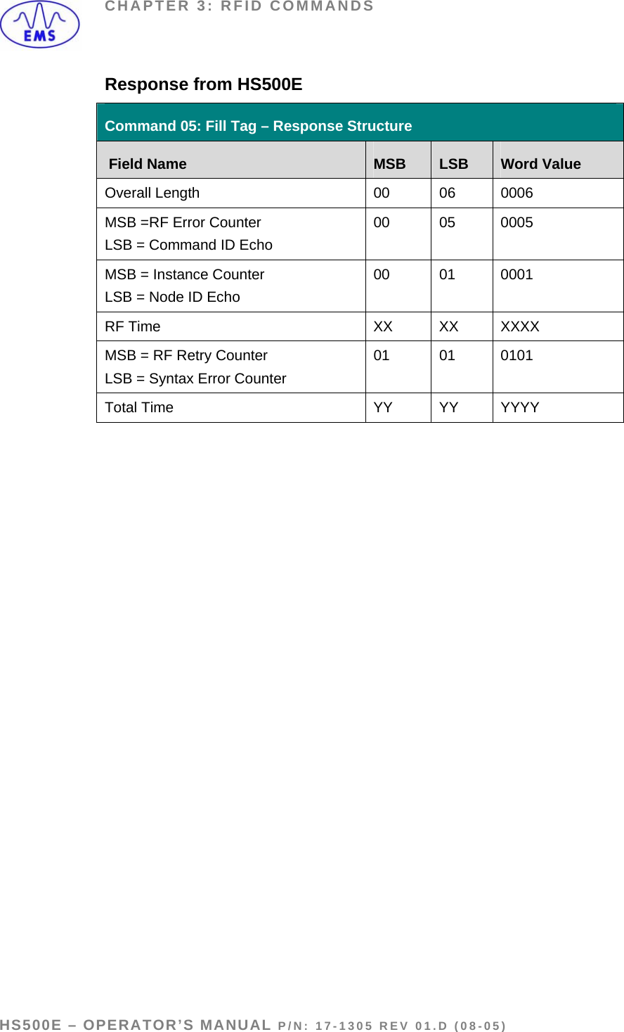
![CHAPTER 3: RFID COMMANDS COMMAND 05: FILL TAG DESCRIPTION Command 05 writes one byte of data across a specified range of tag memory. DISCUSSION This command is used to instruct the HS500E to write a particular data byte value to all specified contiguous areas of tag memory beginning at the Start Address. EXAMPLE In this example, the Ethernet Antenna will write the ASCII character “D” (0x44) to 8-bytes of tag memory starting at address 0x0001. A Timeout Value of 5 seconds is set for the completion of this command. Command from Host Command 05: Fill Tag – Command Structure Field Name MSB LSB Word Value Overall Length 00 06 0006 [0xAB] + Command ID Number AB 05 AB05 MSB = Data Byte Value used for the fill. LSB = Node ID # (always 0x01) 44 01 4401 Timeout Value 00 32 0032 Start Address 00 01 0001 Fill Length 00 08 0008 HS500E – OPERATOR’S MANUAL P/N: 17-1305 REV 01.D (08-05) PAGE 38 OF 51](https://usermanual.wiki/Balluff/M56HSAREI0100/User-Guide-580816-Page-38.png)
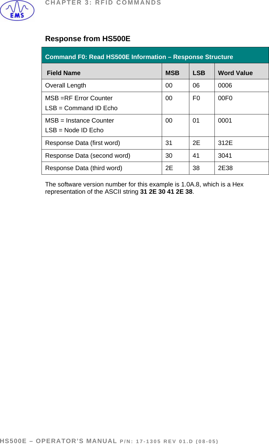
![CHAPTER 3: RFID COMMANDS COMMAND F0: READ HS500E INFORMATION DESCRIPTION Command F0 retrieves the currently installed software version number from the HS500E. DISCUSSION This command queries the Ethernet Antenna’s flash memory and retrieves its software version number. EXAMPLE In this example the software version number (1.0A.8) will be retrieved from the EHS500E. (Note: the “period” between characters is also considered part of the software version number). Timeout Value, Start Address and Read/Write Length are not applicable for this command, default value for each = 0x00, 0x00. Command from Host Command F0: Read HS500E Information – Command Structure Field Name MSB LSB Word Value Overall Length 00 06 0006 Command ID Number + [0x00] F0 00 F000 MSB = 0x00 LSB = Node ID #: (always 0x01) 00 01 0001 Timeout Value 00 00 0000 Start Address 00 00 0000 Read/Write Length 00 00 0000 HS500E – OPERATOR’S MANUAL P/N: 17-1305 REV 01.D (08-05) PAGE 40 OF 51](https://usermanual.wiki/Balluff/M56HSAREI0100/User-Guide-580816-Page-40.png)
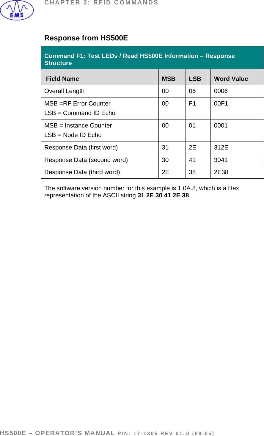
![CHAPTER 3: RFID COMMANDS COMMAND F1: TEST LEDS / READ HS500E INFORMATION DESCRIPTION Command F1 tests the HS500E’s LEDs and also retrieves its software version number. DISCUSSION This command causes the Ethernet Antenna’s LEDs to flash a coded diagnostic pattern while also retrieving the installed software version number. EXAMPLE In this example the LEDs on the Ethernet Antenna will be tested and its software version number will be retrieved. Timeout Value, Start Address and Read/Write Length parameters are not applicable. Command from Host Command F1: Test LEDs / Read HS500E Information – Command Structure Field Name MSB LSB Word Value Overall Length 00 06 0006 Command ID Number + [0x00] F1 00 F100 MSB = 0x00 LSB = Node ID # (always 0x01) 00 01 0001 Timeout Value 00 00 0000 Start Address 00 00 0000 Read/Write Length 00 00 0000 HS500E – OPERATOR’S MANUAL P/N: 17-1305 REV 01.D (08-05) PAGE 42 OF 51](https://usermanual.wiki/Balluff/M56HSAREI0100/User-Guide-580816-Page-42.png)