BROWAN COMMUNICATIONS 1254XW Dual Radio 802.11a/n+b/g/n Indoor Access Point User Manual BW1254 UG EN FCC v1 0
BROWAN COMMUNICATIONS Co., Ltd. Dual Radio 802.11a/n+b/g/n Indoor Access Point BW1254 UG EN FCC v1 0
Contents
- 1. manual
- 2. Manual
manual

Dual Radio 802.11a/n+b/g/n Indoor
Access Point
BW1254
User’s Guide v1.0

BW1254 User Guide v1.0 Nov. 2013
Page 1 of 184
Copyright
© 2002-2013 BROWAN COMMUNICATIONS.
This USER GUIDE is copyrighted with all rights reserved. No part of this publication may be
reproduced, transmitted, transcribed, stored in a retrieval system, or translated into any language in
any form by any means without the written permission of BROWAN.
Notice
BROWAN reserves the right to change specifications without prior notice.
While the information in this document has been compiled with great care, it may not be deemed an
assurance of product characteristics. BROWAN shall be liable only to the degree specified in the
terms of sale and delivery.
The reproduction and distribution of the documentation and software supplied with this product and
the use of its contents is subject to written authorization from BROWAN.
Trademarks
The product described in this book is a licensed product of BROWAN.
Microsoft, Windows 95, Windows 98, Windows Millennium, Windows NT, Windows 2000, Windows
XP, Windows 7,and MS-DOS are registered trademarks of the Microsoft Corporation.
Novell is a registered trademark of Novell, Inc.
MacOS is a registered trademark of Apple Computer, Inc.
Java is a trademark of Sun Microsystems, Inc.
Wi-Fi is a registered trademark of Wi-Fi Alliance.
All other brand and product names are trademarks or registered trademarks of their respective
holders.

BW1254 User Guide v1.0 Nov. 2013
Page 2 of 184
FederalCommunicationCommissionInterferenceStatement
This equipment has been tested and found to comply with the limits for a Class B digital device,
pursuant to Part 15 of the FCC Rules. These limits are designed to provide reasonable protection
against harmful interference in a residential installation. This equipment generates, uses and can
radiate radio frequency energy and, if not installed and used in accordance with the instructions, may
cause harmful interference to radio communications. However, there is no guarantee that interference
will not occur in a particular installation. If this equipment does cause harmful interference to radio or
television reception, which can be determined by turning the equipment off and on, the user is
encouraged to try to correct the interference by one of the following measures:
- Reorient or relocate the receiving antenna.
- Increase the separation between the equipment and receiver.
- Connect the equipment into an outlet on a circuit different from that
to which the receiver is connected.
- Consult the dealer or an experienced radio/TV technician for help.
FCC Caution: Any changes or modifications not expressly approved by the party responsible for
compliance could void the user's authority to operate this equipment.
This device complies with Part 15 of the FCC Rules. Operation is subject to the following two
conditions: (1) This device may not cause harmful interference, and (2) this device must accept any
interference received, including interference that may cause undesired operation.
IMPORTANT NOTE:
Radiation Exposure Statement:
This equipment complies with FCC radiation exposure limits set forth for an uncontrolled environment.
This equipment should be installed and operated with minimum distance 20cm between the radiator &
your body.
This transmitter must not be co-located or operating in conjunction with any other antenna or
transmitter.
Country Code selection feature to be disabled for products marketed to the US/CANADA
Operations in the 5.15-5.25GHz / 5.470 ~ 5.725GHz band are restricted to indoor usage only.
The band from 5600-5650MHz will be disabled by the software during the manufacturing and cannot
be changed by the end user.
This device meets all the other requirements specified in Part 15E, Section 15.407 of the FCC Rules.

BW1254 User Guide v1.0 Nov. 2013
Page 3 of 184
Copyright ............................................................................................................................................. 1
Notice .................................................................................................................................................. 1
Trademarks ......................................................................................................................................... 1
CONTENTS ............................................................................................................................................ 3
ABOUT THIS GUIDE .............................................................................................................................. 6
Purpose ............................................................................................................................................... 6
Prerequisite Skills and Knowledge ...................................................................................................... 6
Conventions Used in this Document ................................................................................................... 6
CHAPTER 1 – INTRODUCTION ............................................................................................................ 7
Product Overview ................................................................................................................................ 7
Features Highlight ............................................................................................................................... 8
CHAPTER 2 - INSTALLATION .............................................................................................................. 9
The Product Package .......................................................................................................................... 9
Hardware Introduction ......................................................................................................................... 9
General Overview ............................................................................................................................ 9
Front panel ....................................................................................................................................... 9
Rear panel ..................................................................................................................................... 10
Bottom Cover ................................................................................................................................. 10
Back label ...................................................................................................................................... 11
Right side: ...................................................................................................................................... 11
Left side ......................................................................................................................................... 12
Connect to the Power Source and Local Network ............................................................................ 12
Access to your access point .............................................................................................................. 13
Configuration .................................................................................................................................. 13
CHAPTER 3 – REFERENCE MANUAL----AP MODE ......................................................................... 15
Web Interface .................................................................................................................................... 15
Status ................................................................................................................................................ 16
Status | Device Status ................................................................................................................... 16
Status | Wireless Status ................................................................................................................. 18
Status | Dynamic Bridge Status ..................................................................................................... 18
Status | Interface Statistics ............................................................................................................ 19
Network ............................................................................................................................................. 20
Network | Interface ......................................................................................................................... 20
Network | Bridge ............................................................................................................................ 21
Network | Attack Countermeasure ................................................................................................. 22
Network | RADIUS Server ............................................................................................................. 23
Network | RADIUS Properties ........................................................................................................ 27
Network | DHCP ............................................................................................................................. 28
Network | DHCP Lease .................................................................................................................. 32
Network | Link Integrity .................................................................................................................. 32
Network | WAPI Certificate Upload ................................................................................................ 34
Network | Tr069 Settings ............................................................................................................... 34
Wireless ............................................................................................................................................. 37
Wireless | Basic ............................................................................................................................. 37
Wireless | Advanced ...................................................................................................................... 43
Wireless | WEP .............................................................................................................................. 52
Wireless | MAC ACL ...................................................................................................................... 54
Wireless | Layer 2 Isolation(Inter-BSS) .......................................................................................... 56
Contents

BW1254 User Guide v1.0 Nov. 2013
Page 4 of 184
Wireless | Neighbor List ................................................................................................................. 58
Wireless | Priority 5G ..................................................................................................................... 59
User ................................................................................................................................................... 61
User | Users ................................................................................................................................... 61
User | Station Supervision ............................................................................................................. 63
Services ............................................................................................................................................. 64
Services | Telnet ............................................................................................................................ 64
Services | SNMP ............................................................................................................................ 65
Services | Time .............................................................................................................................. 66
Services | NTP ............................................................................................................................... 66
Services | Watchdog ...................................................................................................................... 69
System ............................................................................................................................................... 70
System | Administrator ................................................................................................................... 70
System | System Log ..................................................................................................................... 71
System | System Mode .................................................................................................................. 72
System | System Info ..................................................................................................................... 73
System | Configuration .................................................................................................................. 74
System | Reset and Reboot ........................................................................................................... 75
System | Local Upgrade ................................................................................................................ 76
System | TFTP Upgrade ................................................................................................................ 77
System | Location Settings ............................................................................................................ 78
CHAPTER 4 – REFERENCE MANUAL----AP-ROUTER MODE ......................................................... 79
Web Interface .................................................................................................................................... 79
Status ................................................................................................................................................ 81
Status | Device Status ................................................................................................................... 81
Status | Wireless Status ................................................................................................................. 82
Status | Interface Statistics ............................................................................................................ 82
Network ............................................................................................................................................. 84
Network | Interface ......................................................................................................................... 84
Network | PPPoE ........................................................................................................................... 86
Network | L2TP .............................................................................................................................. 87
Network | RADIUS Server ............................................................................................................. 89
Network | RADIUS Properties ........................................................................................................ 93
Network | DNS ............................................................................................................................... 95
Network | DHCP ............................................................................................................................. 96
Network | DHCP Lease .................................................................................................................. 99
Network | Static Route ................................................................................................................... 99
Network | Attack Countermeasure ............................................................................................... 100
Network | Link Integrity ................................................................................................................ 100
Network | Tr069 Settings ............................................................................................................. 102
Wireless ........................................................................................................................................... 105
Wireless | Basic ........................................................................................................................... 105
Wireless | Advanced .................................................................................................................... 111
Wireless | WEP ............................................................................................................................ 118
Wireless | MAC ACL .................................................................................................................... 120
User ................................................................................................................................................. 123
User | Users ................................................................................................................................. 123
User | Station Supervision ........................................................................................................... 125
User | User ACL ........................................................................................................................... 126
User | Walled Garden .................................................................................................................. 128
User | WISP ................................................................................................................................. 129
User | Start Page ......................................................................................................................... 131
User | Customized UAM .............................................................................................................. 132
User | Pages ................................................................................................................................ 136
User | Upload ............................................................................................................................... 138
User | HTTP Headers .................................................................................................................. 138
User | Remote Authentication ...................................................................................................... 139

BW1254 User Guide v1.0 Nov. 2013
Page 5 of 184
Services ........................................................................................................................................... 140
Services | Telnet .......................................................................................................................... 140
Services | SNMP .......................................................................................................................... 140
Services | NTP ............................................................................................................................. 141
Services | Time ............................................................................................................................ 144
Services | Watchdog .................................................................................................................... 144
System ............................................................................................................................................. 146
System | Administrator ................................................................................................................. 146
System | System Log ................................................................................................................... 147
System | System Mode ................................................................................................................ 148
System | System Info ................................................................................................................... 149
System | Configuration ................................................................................................................ 150
System | Reset and Reboot ......................................................................................................... 151
System | Local Upgrade .............................................................................................................. 152
System | TFTP Upgrade .............................................................................................................. 153
System | Location Settings .......................................................................................................... 154
CHAPTER 5 – USER PAGES (BASED ON XSL).............................................................................. 155
User Pages Overview ...................................................................................................................... 155
Welcome Page............................................................................................................................. 155
Login Page ................................................................................................................................... 155
Logout Page ................................................................................................................................. 156
Help Page .................................................................................................................................... 157
Unauthorized Page ...................................................................................................................... 158
Example for External Pages ........................................................................................................ 158
Example for Internal Pages ......................................................................................................... 161
Extended UAM ................................................................................................................................ 164
Parameters Sent to WAS ............................................................................................................. 166
CHAPTER 6 – CUSTOMIZED USER PAGE (HTML) ........................................................................ 170
Set up your customized user page .................................................................................................. 170
FAQ ................................................................................................................................................. 175
APPENDIX .......................................................................................................................................... 176
A) Specification ............................................................................................................................... 176
B) Factory Defaults for the BW1254 ............................................................................................... 177
Network Interface Configuration Settings .................................................................................... 177
User Settings ............................................................................................................................... 179
System Settings ........................................................................................................................... 179
C) Location ID and ISO Country Codes .......................................................................................... 180
BW1254 User Guide v1.0 Nov. 2013
Page 6 of 184
Purpose
This document provides information and procedures on hardware installation, setup, configuration,
and management of the high performance Indoor Access Point BW1254.
Prerequisite Skills and Knowledge
To use this document effectively, you should have a working knowledge of Local Area Networking
(LAN) concepts and wireless Internet access infrastructures. In addition, you should be familiar with
the following:
Hardware installers should have a working knowledge of basic electronics and mechanical
assembly, and should understand related local building codes.
Network administrators should have a solid understanding of software installation procedures for
network operating systems under Microsoft Windows 95, 98, Millennium, 2000, NT, and Windows
XP and general networking operations and troubleshooting knowledge.
Conventions Used in this Document
The following typographic conventions and symbols are used throughout this document:
Very important information. Failure to observe this may result in damage.
Important information that should be observed.
Additional information that may be helpful but which is not required.
bold Menu commands, buttons and input fields are displayed in bold
code File names, directory names, form names, and system-generated output
such as error messages are displayed in constant-width type
<value> Placeholder for certain values, e.g. user inputs
[value] Input field format, limitations, and/or restrictions.
About this Guide

BW1254 User Guide v1.0 Nov. 2013
Page 7 of 184
Thank you for choosing the Indoor Access Point BW1254.
The BW1254 is fully compliant to 802.11a/b/g/n standard and provides the flexibility of different kinds
of 802.11n, 802.11a, 802.11g or 802.11b clients access to the BW1254. With the high speed data
rate(Max. 300Mbps) and security, feature rich software functionality, it provides the high performance
wireless connection for the SMB, enterprise, and hotspot of public area.
Product Overview
Flexibility and high performance
BW1254 is a high-performance and feature-rich indoor Access Point. It provides high quality
connectivity for Wi-Fi networks designed to support large hotspots. The platform providing powerful
hardware processing ability and maximize its service coverage for deploying enterprise-scale Wi-Fi
networks including warehouses, universities, airports, hospitals, and large corporations.
z Support IEEE802.11a/b/g/n Wi-Fi standard.
z Wireless AP router mode: NAT, Different IP subnet per BSSID, Support DHCP server or client.
z FAT AP with AP or AP Router mode configuration.
z Point to point or smart point to multi-point bridge.
Secure and reliable wireless networking
BW1254 supports and meets industry security requirement of wide area networking professionals for
secured wireless network:
z Supports VLAN, up to 16 VLAN ID
z IEEE 802.1x/EAP with password, certificates and SIM card
z 64bits/128bits static and dynamic WEP encryption
z Supports Wi-Fi Protected Access (WPA/WPA2) with AES and TKIP support
z Layer 2 Isolation for preventing snooping on the same BSS
z MAC address filtering (ACL) for preventing illegal attacking from Internet
z Hidden SSID broadcast to prevent illegal users connection
z Built-in Web login authentication (UAM, AP Router mode)
Strong Anti-interference
Dynamic Channel Allocation (DCA) solution automatically selects optimal operational frequency
channel during power up and the periodically monitors the environment and adjusts for best
operational channel. DCA enhances BW1254 performance and provide continuous coverage under
high AP density wireless network environment.
Multiple BSSID “Virtual AP” Technology
Supports up to16 BSSID and each can be configured independently to support range of security
policies, authentication model, RADIUS servers and VLAN IDs. Each BSSID also can be set different
priority based on 802.1p tag or 802.11e EDCA which enables WLAN client device to access wireless
link QoS capabilities.
Chapter 1 – Introduction

BW1254 User Guide v1.0 Nov. 2013
Page 8 of 184
Ease Installation and Deployment
Power option includes an integrated IEEE 802.3at Power-over-Ethernet port enables effortless
deployment in various environments.
Easy and Secure Remote Management
BW1254 supports secure remote management through HTTPS, CLISH, SNMP and TR-069(DMS)
management.
z Secure management via HTTPs, CLISH, SNMP
z Support TR-069 protocol
z Detail client survey and site survey
z Remote firmware update via WEB UI, BROWAN DMS server
z Backup/Restore configuration file
z Command Line Interface(CLI) with optional SSH
z Simple Network Management Protocol(V1,V2)
Features Highlight
Support IEEE802.11a/b/g/n Wi-Fi standard.
Superior Wireless Bridging Capability (PtP, PtMP)
Support up to 16 BSSID – “Virtual AP”
Wi-Fi Protected Access (WPA and WPA2) with TKIP or AES
Wired Equivalent Privacy (WEP) using static or dynamic key of 64 or 128 bits
Anti-Interference with Dynamic Channel Allocation (DCA)
Hidden SSID for blocking illegal users accessing
Supports 802.1x authentication using EAP-TLS, EAP-TTLS, PEAP, and SIM
MAC Access Control List (ACL)
Layer2 Isolation for Peer to Peer client access protection
Built-in Web user login Authentication
DHCP server, DHCP client
Support up to 16 VLAN ID
RADIUS authentication
Wireless Quality of Service
Backup/Restore configuration settings
System Log, Save/Send System Log to remote log server with different log levels
NTP for clock Synchronization
Remote firmware upgrade via HTTP
Remote secure management by HTTPS and SNMP
Software watchdog supported
BW1254 User Guide v1.0 Nov. 2013
Page 9 of 184
This chapter provides installation instructions for the hardware and software components of the
Access Point BW1254. It also includes the procedures for the following tasks:
Hardware Introduction (LEDs, Connectors)
Connecting the Access Point
Software Installation
The Product Package
The product comes with the following:
Dual Radio 802.11a/n+b/g/n Indoor Access Point (model: BW1254)
Screw Bag(wall mounting)
Antenna (Dual-band Dipole Antennas with RP-SMA connector, 4 units)
Ethernet patch cable (Cat5 UTP, 1.5m length, 1 unit)
External power supply (Input:100-240VAC, 50-60Hz, Output: 48VDC/0.5A, 1 unit)
Hardware Introduction
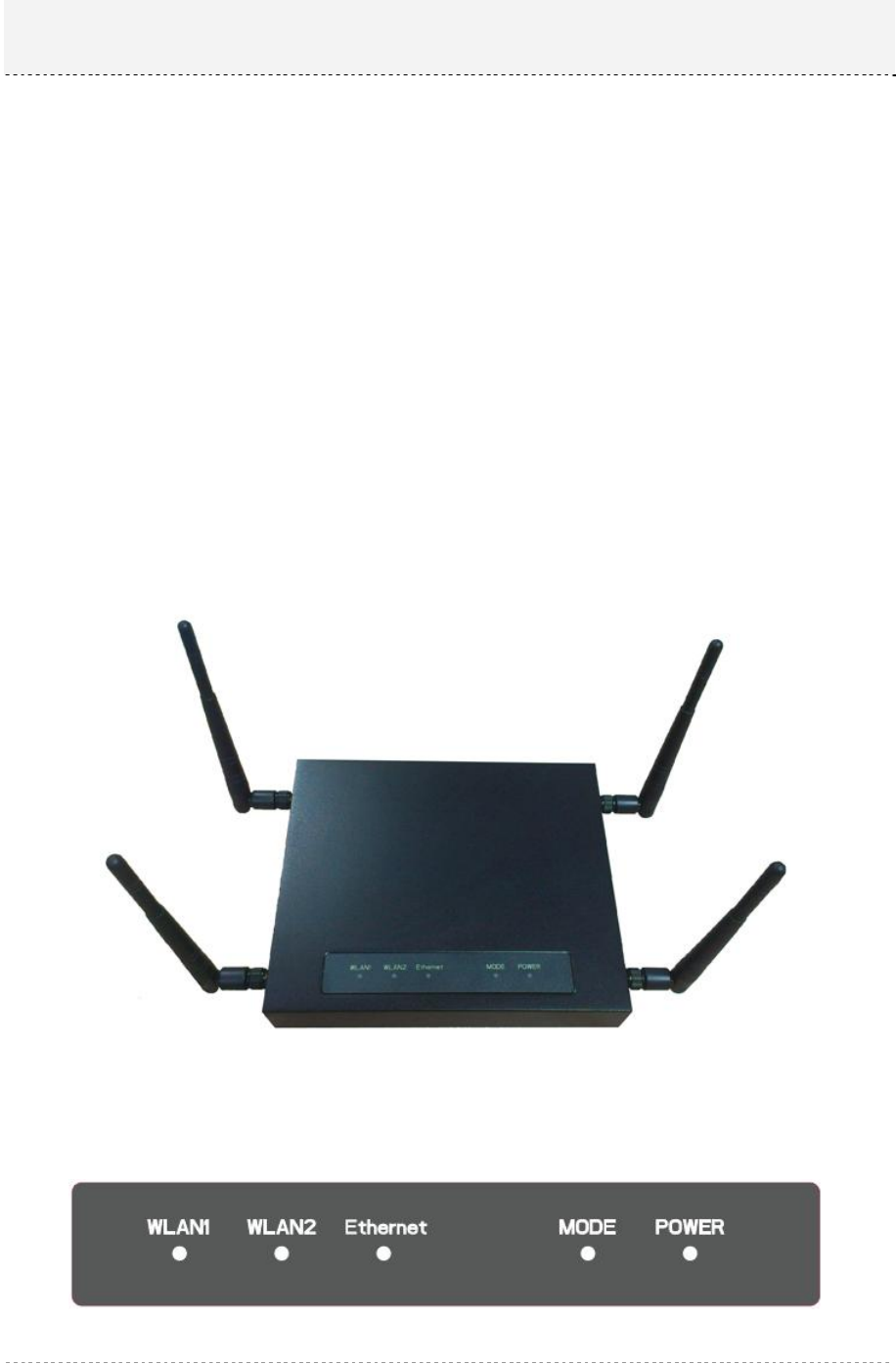
General Overview
Figure 1 – BW1254 General View
Front panel
There are five indicator lights (LEDs) that help to describe the state of various networking and
connection operations.
Figure 2 – BW1254 led indication
Chapter 2 - Installation
BW1254 User Guide v1.0 Nov. 2013
Page 10 of 184
LED Indicators
LED Indication
Power(Green) ON: the unit is power on and ready to work
Blinking : the device is booting
Off : the unit is power off
Mode Green : AP is working
Blinking(both green and amber) : the AP is
firmware upgrading
Ethernet Green : network speed of 1000Mbps
Amber : network speed of 10/100Mbps
Off : Ethernet link is unavailable
WLAN 1(Green) Blinking : the radio is operating
Off : radio disable
WLAN 2(Green) Blinking : the radio is operating
Off : radio disable
table 1 – BW1254 led definition
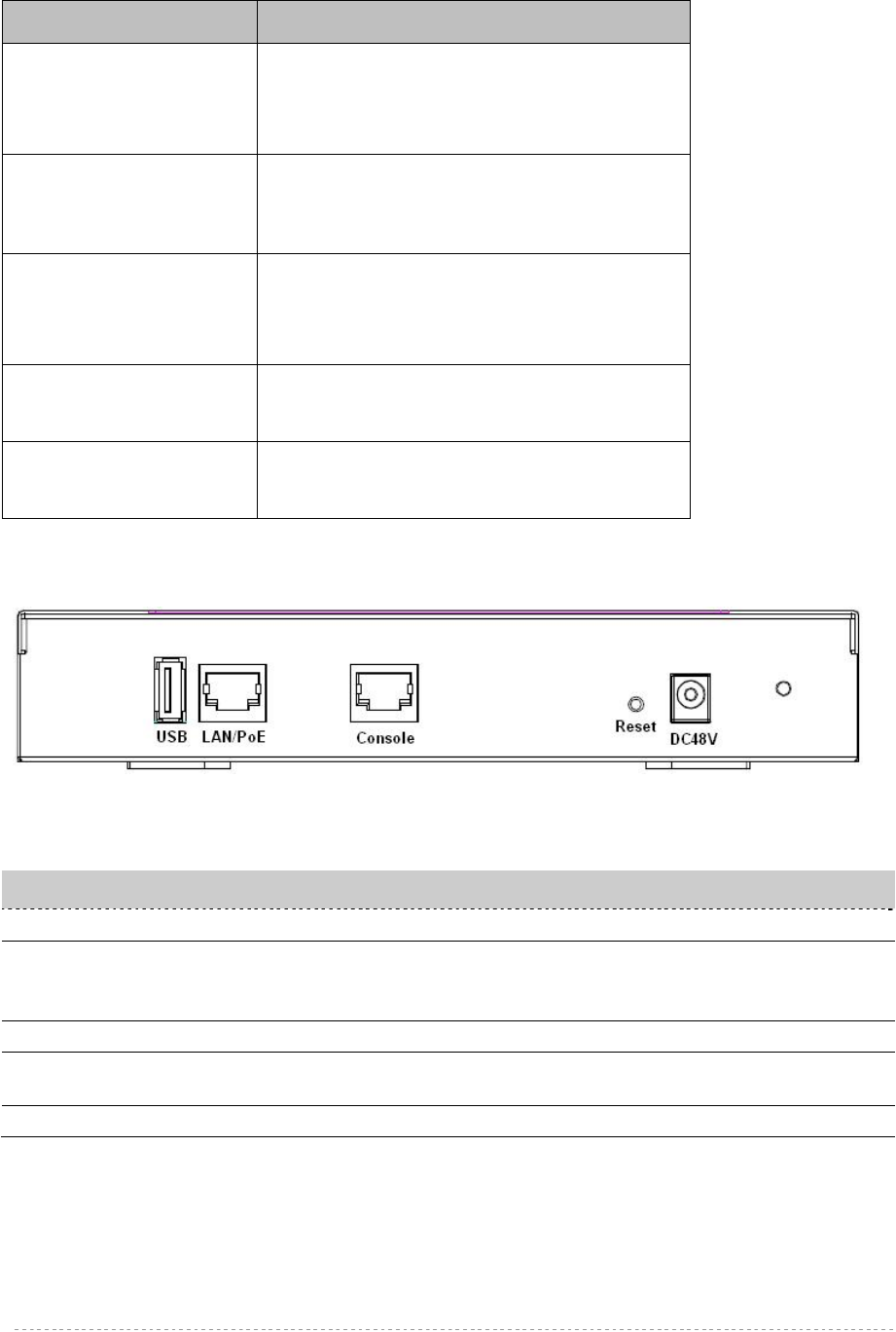
Rear panel
Figure 3 – rear panel I/O port
Descriptions of the connectors are given in the following table:
table 2 – BW1254 connectors
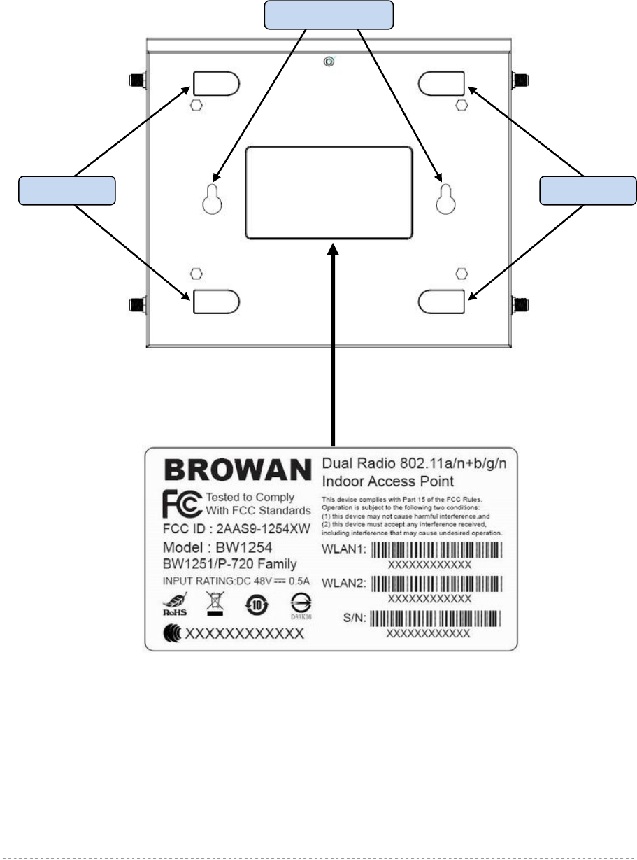
Bottom Cover
The Bottom Cover of the BW1254 contains:
Item Connector Description
1 DC48V For power supply 48V DC jack
2 Reset button Reboot or Reset device
Press reset button to reboot device or keep press for more
than 5 seconds to reset factory default configuration.
3 Console For console connection(RJ-45 interface)
4 LAN/PoE Connecting RJ-45 cable to Ethenet network and for PoE
power supply.
5 USB reserved
BW1254 User Guide v1.0 Nov. 2013
Page 11 of 184
1. Back Label with MAC address and S/N, model name, certification…etc.
2. MAC address. The label shows the WLAN interface MAC address of the device.
WLAN 1:the radio MAC for 2.4G
WLAN 2:the radio MAC for 5G
The LAN MAC= WLAN 1 MAC + 1(Hex, AP mode)
The WAN MAC=WLAN 1 MAC + 1(Hex, AP router mode)
3. Serial Number of the device.
4. Rubber foot
5. Wall mount hole
Figure 4 –Bottom Cover of the BW1254
Back label
The back label format and location as below.
Figure 5 – back label
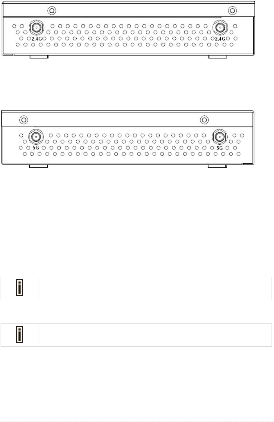
Right side:
Two RP-SMA type of antenna connectors for WLAN 1(2.4G)
Wall mount hole
Rubber foo
t
Rubber foo
t
BW1254 User Guide v1.0 Nov. 2013
Page 12 of 184
Figure 6 – SMA antenna connector(2.4G)
Left side
Two RP-SMA type of antenna connectors for WLAN 2(5G)
Figure 7 – RP-SMA antenna connector(5G)
Connect to the Power Source and Local Network
There are two power supply methods can be used by BW1254:
♦ Power-over-Ethernet equipment
♦ 48VDC Power adapter
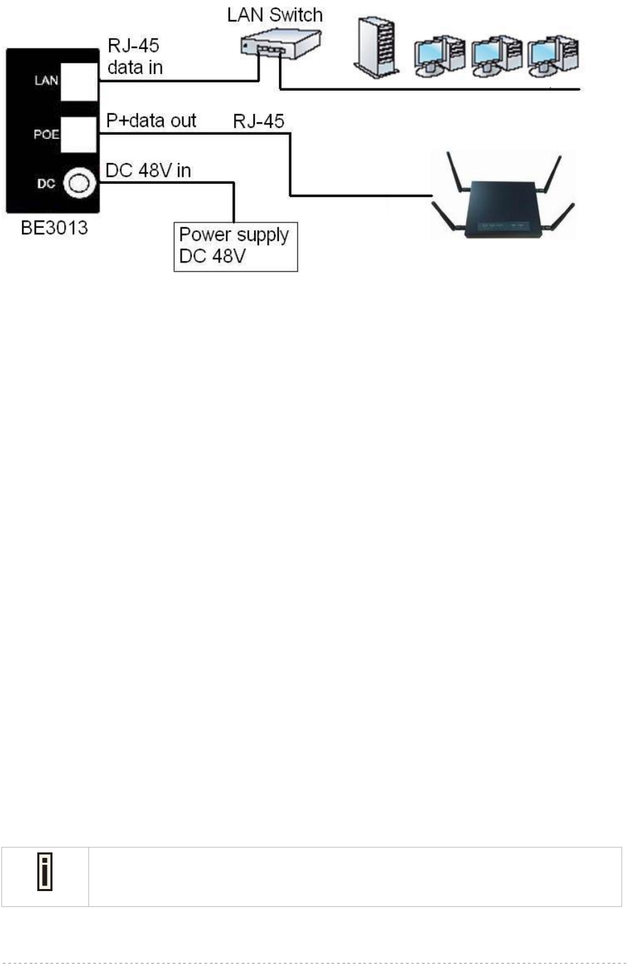
Case 1 Use the BROWAN BE3013 PoE injector+DC 48V power adapter:
BE3013 PoE injector is optional which is non-compliant to 802.3at.
BW1254 is compliant to 802.3at PoE standard.
Step 1 Place the Access Point on a flat work surface or hang on the wall.
Use the enclosed 2 screws mounting the Access Point to the wall if necessary.
Step 2 Connect DC 48V power supply to PoE injector DC jack.
Step 3 Connect the Ethernet cable from the BW1254 to PoE injector “P+data” out port.
Step 4 Connect Ethernet cable from PoE injector “data in” port to the computer or through LAN
switch connect to your local network. Please refer to the figure shown as below.
BW1254 User Guide v1.0 Nov. 2013
Page 13 of 184
Figure 8 – Connecting BW1254 to Power source and network by PoE
Case 2 Use External Power Supply
Step 1 Place the Access Point on a flat work surface or hang on the wall.
Step 2 Use the enclosed Ethernet patch cable to connect the LAN port of the Access Point to the
Switch or hub in the local network.
Step 3 Connect the power supply to the Access Point.
Access to your access point
Configuration
Now it is ready to access and configure your access point. Open web browser and enter ip address.
The default ip address for your new access point is:
IP 192.168.2.2 subnet 255.255.255.0
Step 1 Configure your PC with a static IP address on the 192.168.2.x subnet with mask
255.255.255.0. Connect the BW1254 into the same physical network as your PC.
Open the Web browser and type the default IP address of the BW1254:
https://192.168.2.2/a.rg
Step 2 Enter the BW1254 administrator login details to access the Web management.
The default administrator log on settings for all access point interfaces are:
User Name: admin
Password: admin01
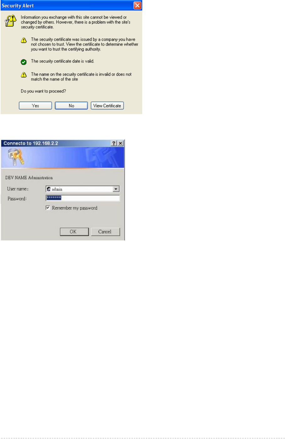
Continuously clicking Yes to proceed.
BW1254 User Guide v1.0 Nov. 2013
Page 14 of 184
Figure 9 – Security alert
Figure 10 – login page
Step 3 After successful administrator log on you will see the main page of the BW1254 Web
interface:
Figure 11 – Web interface Management Menu
Now you are enabled to perform your configuration.
BW1254 User Guide v1.0 Nov. 2013
Page 15 of 184
This chapter describes the configuration of the BW1254 which works in AP mode using the Web
Interface.
The BW1254 Web Interface in AP mode is different from that in AP-Router mode. To
change your BW1254 to AP-Router mode, please refer to System | System Mode .
For the detailed configuration of BW1254 working in AP-Router mode, please refer to
the next chapter: Chapter 4 – Reference Manual----AP-Router Mode
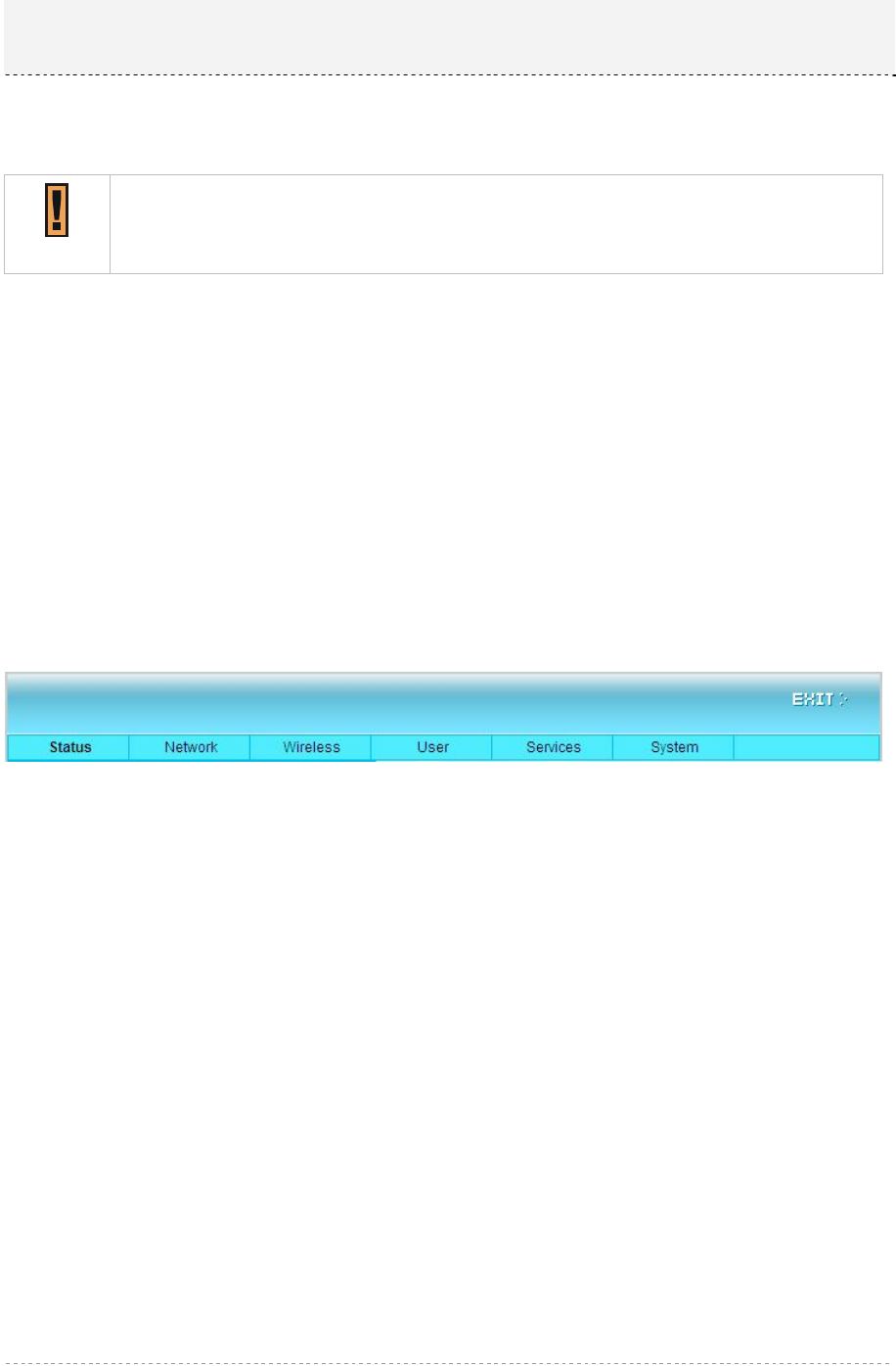
The web management main menu consists of the following sub menus:
Status – device status showing
Network – device settings affecting networking
Wireless – device settings related to the wireless part of the BW1254
User –device settings affecting the user interface
Services – networking service settings of the BW1254
System – device system settings directly applicable to the BW1254
Exit – click exit and leave the web management then close your web-browser window.
Web Interface
The main web management menu is displayed at the top of the page after successfully logging into
the system (see the figure below). From this menu all essential configuration pages are accessed.
Figure 12 – Main Configuration Management Menu
The web management menu has the following structure:
Status
Device Status – show the status related with the whole device
Wireless Status – show the status of the two radios
Dynamic Bridge Status – show the dynamic bridge status of the two radios
Interface Statistics – show the status of each network interface
Network
Interface – TCP/IP settings of BW1254 LAN (Bridge) port
Bridge – 802.1d settings of BW1254 bridge port
Attack Countermeasure – Anti-attack settings for protecting BW1254
RADIUS Server – specify the accounting/authentication RADIUS server which is used by
802.1x or WPA
RADIUS Properties – specify the settings of the RADIUS properties, includes NAS server ID,
RADIUS Retries and other settings
DHCP – specify the settings of DHCP server service
DHCP lease – display the DHCP lease information
Link Integrity – specify the status and settings of link integrity feature.
Chapter 3 – Reference Manual----AP Mode

BW1254 User Guide v1.0 Nov. 2013
Page 16 of 184
WAPI Certificate Upload – configure the WAPI certificate
Tr069 settings – configure the remote management through TR069 ACS server(BROWAN
DMS server)
Wireless
Basic – specify the basic settings related with wireless part
Advance – specify the settings of multiple BSSID or Bridge
WEP – specify the WEP settings related with static WEP encryption
MAC ACL – MAC ACL settings for BW1254
Layer 2 Isolation – Inter-BSS layer2 Isolation settings of BW1254
Neighbor list – scan the neighbor AP of 2.4G/5G
Priority 5G – configure the 5G priority
User
Users – show the connected users’ statistics list and log-out user function
Station Supervision – monitor station availability with ARP-pings settings
Services
Telnet – Telnet/SSH service
SNMP – SNMP service
Time – manually set time
NTP – NTP settings of BW1254
Watchdog – Enable the S/W or H/W watchdog of BW1254
System
Administrator – set access permission to your BW1254
System Log – check the system log locally or specify address where to send system log file
System Mode – specify whether the BW1254 works in AP mode or in AP router mode
System Info – specify some device related information for BW1254
Configuration – system configuration utilities, including Backup/Upload configuration
Reset & Reboot – reboot device and restore systems to factory default
Local Upgrade – upgrade firmware from local PC
TFTP Upgrade –upgrade firmware from tftp server
Location settings – define AP location(Longitude/Latitude)
In the following sections, short references for all menu items are presented.
Status
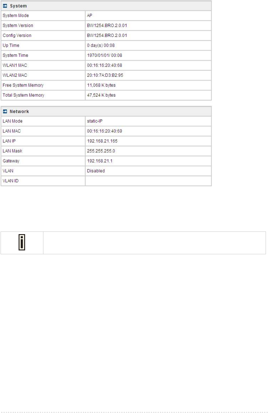
Status | Device Status
The Device Status page shows important information of system status and network configuration for
the BW1254.
BW1254 User Guide v1.0 Nov. 2013
Page 17 of 184
Figure 13 – Device Status
System Mode – display whether the BW1254 works in AP mode or AP-Router mode
System Version display the current firmware version
This is important information for support requests and for preparing firmware
upgrading
Config version – display current configure version
Up Time – indicate the time, expressed in days, hours and minutes since the system was last
rebooted
System Time – show the current time of the BW1254
Wlan1 MAC – show the MAC addresses of the wireless interfaces(2.4G) of the BW1254
Wlan2 MAC – show the MAC addresses of the wireless interfaces(5G) of the BW1254
Free System Memory – indicate the memory currently available in the BW1254
Total System Memory – indicate the total memory in the BW1254
LAN Mode – indicate static IP or DHCP client is used for BW1254 LAN IP address
LAN MAC – display the Ethernet MAC address
LAN IP – show the LAN IP address of BW1254
LAN Mask – show the LAN Network Mask of BW1254
Gateway – show the default gateway of BW1254
VLAN – show the status of LAN Interface VLAN of BW1254
VLAN ID – display VLAN ID if configure the VLAN
BW1254 User Guide v1.0 Nov. 2013
Page 18 of 184
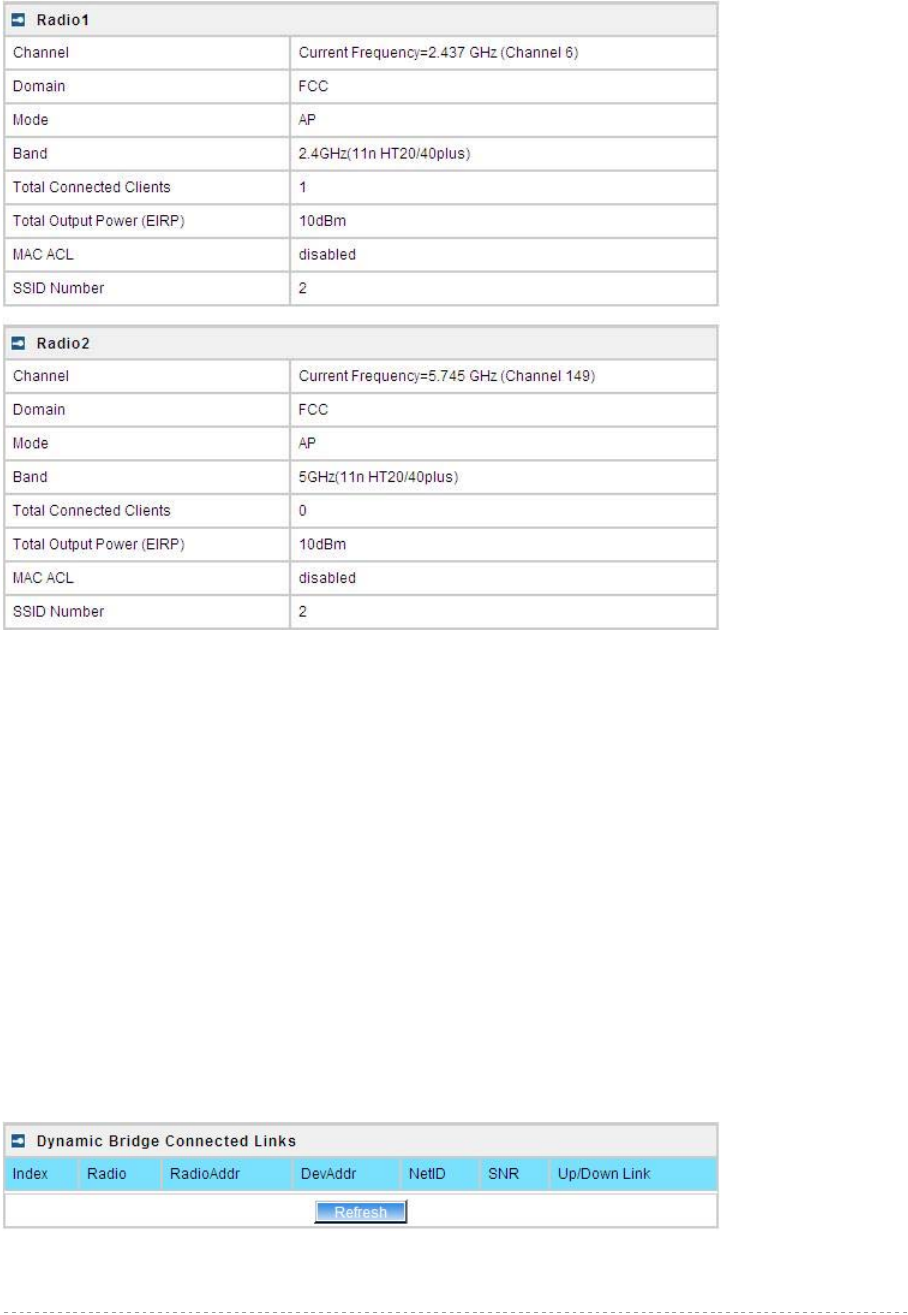
Status | Wireless Status
The wireless status shows the information related with BW1254 wireless interfaces.
Figure 14 – Wireless Status
Radio1/Radio2 –wireless interfaces
Channel – indicate which channel is in use.
Domain – indicate regulatory domain set on the BW1254
Mode – AP or Bridge mode is be used for this wireless interface
Band – specify which band is in use for wireless interface
Total Connected Clients – indicate number of the currently connected clients to your BW1254
Tx Power – indicate radio transmit power of the BW1254
MAC ACL – indicate the status of MAC ACL feature on BW1254
SSID Number – indicate current number of enabled SSID on BW1254
Status | Dynamic Bridge Status
The Dynamic Bridge status shows the status of wireless bridge links.

BW1254 User Guide v1.0 Nov. 2013
Page 19 of 184
Status | Interface Statistics
The Interface Statistics shows each network interface status, including Input / Output bytes, packets
or error.
Figure 15 – Interface Statistics
Interface Name – show the name of each network interface, where ixp0 is related to LAN interface,
wlan1_x is related to wireless sub-interface.
Input Bytes (KB) – show the total number of bytes received on the network interface. The bytes
number is displayed in KB.
Input Packets – show the packets number received on the network interface.
Input Errors – show the packets number which contain errors preventing them from being received
correctly.
Output Bytes (KB) – show the total number of bytes transmitted out of the network interface. The
bytes number is displayed in KB.
Output Packets – show the packets number transmitted out of the network interface.
Output Errors – show the packets number which contain errors preventing them from being
transmitted out correctly.
Refresh – get the updated network interface information.
BW1254 User Guide v1.0 Nov. 2013
Page 20 of 184
Network
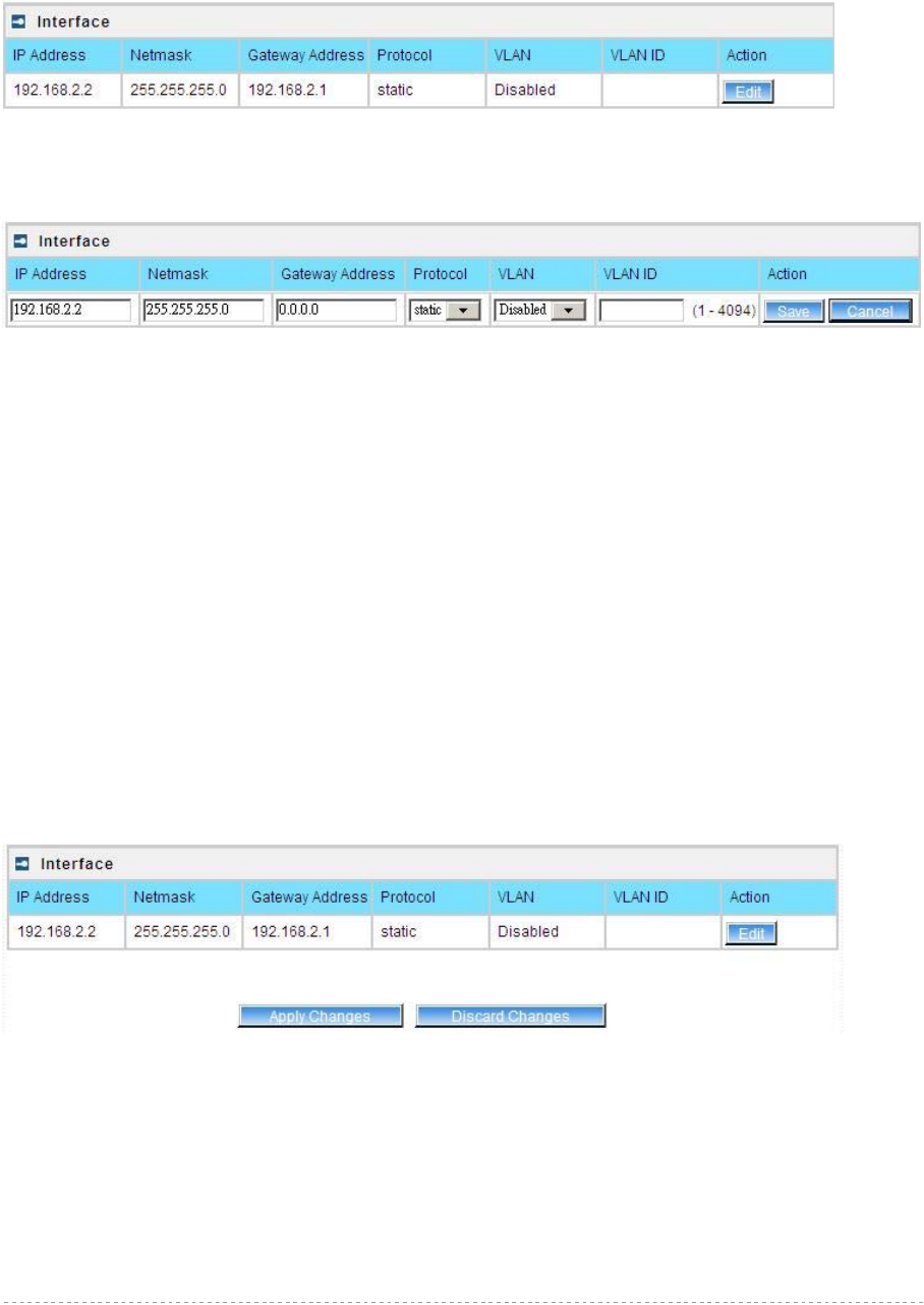
Network | Interface
Figure 16 – Interface Configuration Table
To change network interface configuration properties click the Edit button in the Action column. The
status can be changed now:
Figure 17 – Edit Interface Configuration Settings
IP Address – specify new interface IP address [in digits and dots notation, e.g. 192.168.2.2].
Netmask – specify the subnet mask [[0-255].[0-255].[0-255].[0-255]].These numbers are a binary
mask of the IP address, which defines IP address order and the number of IP addresses in the subnet
Gateway Address – interface gateway. For Bridge type interfaces, the gateway is always the
gateway router
Protocol – specify static for setting IP address manually and dhcp for getting IP address dynamically
acting as DHCP client
VLAN – Enable or disable VLAN on LAN (bridge) interface
VLAN ID – When enabled VLAN, specify the VLAN ID of it
Save – save the entered values.
Cancel – restore all previous values.
Change status or leave in the default state if no editing is necessary and click the Save button.
Figure 18 – Apply or Discard Interface Configuration Changes
Apply Changes – save all changes in the interface table at once.
Discard Changes – restore all previous values.
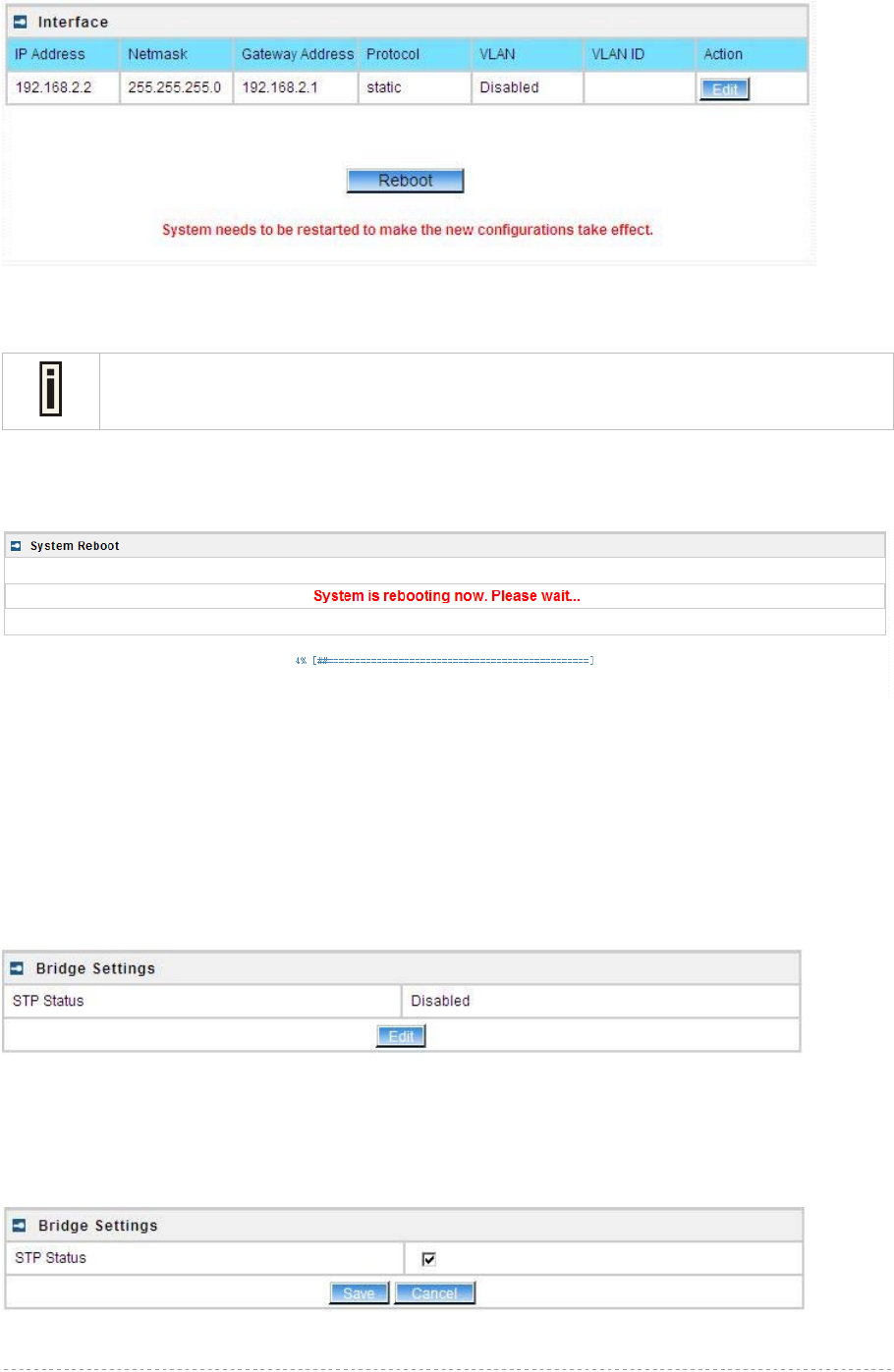
For such change of settings, the BW1254 needs to be restarted to apply all settings changes when
clicking Apply Changes. Request for reboot server appears:
BW1254 User Guide v1.0 Nov. 2013
Page 21 of 184
Figure 19 – Reboot Server
Reboot – click the button to restart the server and apply the changes.
If there is no other settings needed to be modified, click the Reboot button to apply all
changes. If there are any other settings need to be changed, continuously to finish and
apply all changes and then click Reboot button to restart and take effect for all settings.
To reboot at once, click Reboot button and then it is necessary to wait a moment. And the message
of reboot appears just like bellows:
Figure 20 – Reboot Information
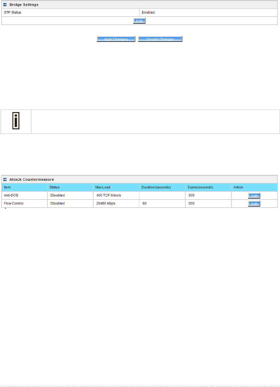
Network | Bridge
The Spanning Tree Protocol is a network protocol that ensures a loop-free topology for any bridged
Ethernet local area network. The basic function of STP is to prevent bridge loops and the broadcast
radiation the results from them.
Specify STP(spanning tree protocol) status of 802.1d bridge here.
Figure21– 802.1d bridge STP settings
STP Status – Enable or disable the 802.1d STP for BW1254
Clicking Edit, the follow UI will be appear:
Figure 22 – Edit bridge settings
BW1254 User Guide v1.0 Nov. 2013
Page 22 of 184
Save – save the entered values.
Cancel – restore all previous values.
Click Save button for applying the changes that modified.
Figure 23 – Apply or Discard Bridge Settings Changes
Apply Changes – save all changes at once
Discard Changes – restore all previous values.
Click Apply Changes and then follow the instruction to reboot the device for all modified settings
applied.
If there is no other settings needed to be modified, click the Reboot button to apply all
changes. If there are any other settings need to be changed, continuously to finish and
apply all changes and then click Reboot button to restart and take effect for all settings.
Network | Attack Countermeasure
To protect BW1254 from outside attack, anti-attack polices can be set here based on network needs.
Figure 24– Attack Countermeasure settings
Anti-DOS
Status – Enable or disable anti-dos policy for BW1254. This policy is for TCP DOS attack.
Max Load – The attack threshold. BW1254 think there is TCP DOS attack and do the
countermeasure if one client’s TCP links exceed this threshold.
Expire(seconds) – If one client is considered as DOS attacker, BW1254 kicks it out and doesn’t
let it connect again during the time that Expire set.
Flow Control
Status – Enable or disable traffic flow control policy for BW1254.
Max Load – The attack throughput threshold.
Duration(seconds) – if traffic exceeds the value of Max Load during the whole time that
Duration set, BW1254 think there is traffic flow attack and implement the
countermeasure.
Expire(seconds) – If one client is considered as traffic flow attacker, BW1254 kicks it out and
doesn’t let it connect again during the time that Expire set.

BW1254 User Guide v1.0 Nov. 2013
Page 23 of 184
Network | RADIUS Server
Up to 32 different RADIUS servers can be configured in the RADIUS servers
menu.
By default, one RADIUS server is specified for the system:
Figure 25 – RADIUS Servers Settings
Details – show the detail information of this RADIUS Server profile
Edit – edit the selected RADIUS Server entry you want to configure
Delete – delete the selected RADIUS Server entry. The last entry can not be deleted
Add – add new RADIUS server.
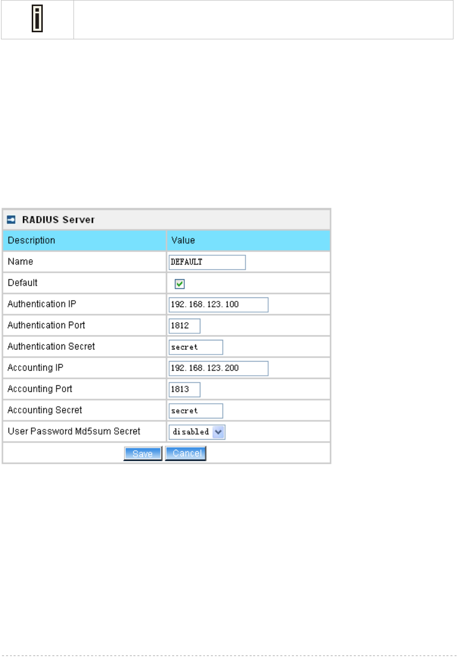
Click Details, a similar page will be appeared as below:
Figure 26 – Detail for Radius Server profile
Name – the new RADIUS server name which is used for selecting RADIUS server
If a “(default)” appears on the right side of the Name entry, it means this RADIUS
server profile is the default profile.
Authentication IP – show the IP address of Authentication RADIUS server
Authentication Port – show the network port used to communicate with the Authentication RADIUS
server
BW1254 User Guide v1.0 Nov. 2013
Page 24 of 184
Authentication Secret – show the shared secret string that is used to make sure the integrity of data
frames used for the Authentication RADIUS server
Accounting IP – show the IP address of Accounting RADIUS server
If the Accounting IP address is 0.0.0.0, it means that the Accounting service is
disabled.
Accounting Port – show the network port used to communicate with the Accounting RADIUS server
Accounting Secret – show the shared secret string that is used to make sure the integrity of data
frames used for the Accounting RADIUS server
User Password Md5sum Secret – show whether user input password is calculated md5-sum before
pass to RADIUS server or not.
Back – back to the RADIUS Server main page
Edit – edit the selected RADIUS Server profile
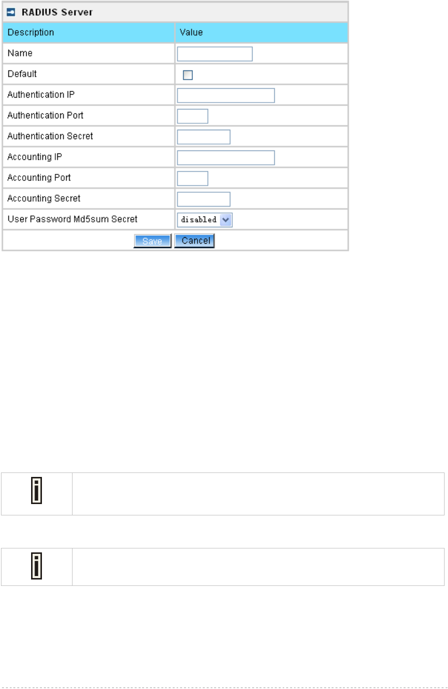
Click Edit or click Add / Edit button in the main page to configure RADIUS server settings.
Figure 27 – Edit the RADIUS Server’s profile
BW1254 User Guide v1.0 Nov. 2013
Page 25 of 184
Figure 28 – Add a new RADIUS Server's profile
Name – specify the new RADIUS server name which is used for selecting RADIUS server
Default – specify this RADIUS profile as default or not. When selected, the profile will be used as
default
Authentication IP – specify the IP address of Authentication RADIUS server [dots and digits]
Authentication Port –specify the network port used to communicate with the Authentication RADIUS
server [1-65535]
Authentication Secret – shared secret string that is used to make sure the integrity of data frames
used for the Authentication RADIUS server
Accounting IP – specify the IP address of Accounting RADIUS server [dots and digits]
Accounting Port –specify the network port used to communicate with the Accounting RADIUS server
[1-65535]
Accounting Secret – shared secret string that is used to make sure the integrity of data frames used
for the Accounting RADIUS server
The default port value for authentication is 1812.
The default port value for accounting is 1813.
The port specified here must be the same with the one on the RADIUS server.
User Password Md5sum Secret – if enabled, user input password will be calculated md5-sum
before pass to RADIUS server for more security [enabled/disabled]
This setting needs RADIUS server implement relevant configurations.
Save –save the entered values
Cancel – restore all previous values
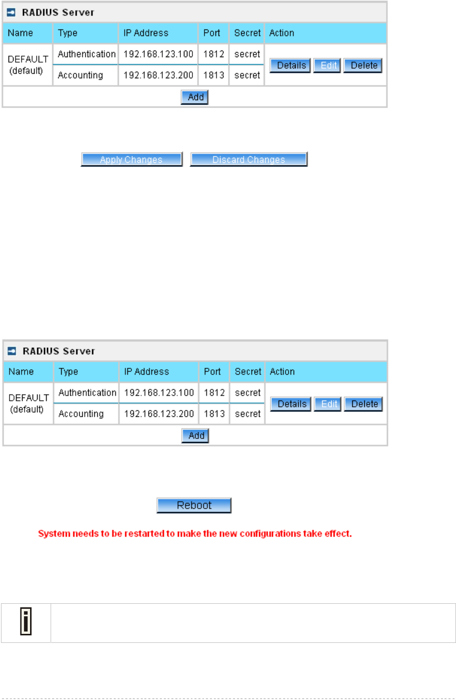
After adding a new RADIUS server or editing an existing one, a page appears similar to the following:
BW1254 User Guide v1.0 Nov. 2013
Page 26 of 184
Figure 29 – Apply or Discard RADIUS Server Changes
Details – show the detail information of this RADIUS Server profile
Edit – edit the selected RADIUS Server entry you want to configure
Delete – delete the selected RADIUS Server entry. The last entry can not be deleted
Add – add new RADIUS server.
Apply Changes – to save all changes at once.
Discard Changes – restore all previous values.
Click Apply Changes to apply all the changes. Then the follow similar page will appear:
Figure 30 – Reboot Server
Reboot – restart the access point to make applied changes work.
If there is no other settings needed to be modified, click the Reboot button to apply all
changes. If there are any other settings need to be changed, continuously to finish and
apply all changes and then click Reboot button to restart and take effect for all settings.
BW1254 User Guide v1.0 Nov. 2013
Page 27 of 184
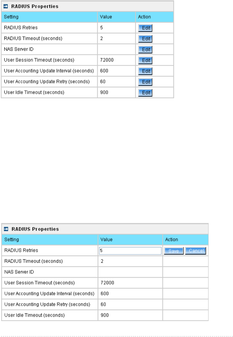
Network | RADIUS Properties
General RADIUS settings are configured using the RADIUS Properties menu under the network:
Figure 31 – RADIUS Properties settings
RADIUS Retries – retry count of sending RADIUS packets before giving up [0-99]
RADIUS Timeout (seconds) – maximum amount of time before retrying RADIUS packets [1-999]
NAS Server ID – name of the RADIUS client
User Session Timeout (seconds) – amount of time from the user side (no network carrier) before
closing the connect [1-999999999]
User Accounting Update Interval (Seconds) – period after which server should update accounting
information [60-999999999]
User Accounting Update Retry (seconds) – retry time period in which server should try to update
accounting information before giving up [60-999999999]
User Idle Timeout (seconds) – amount of user inactivity time, before automatically disconnecting
user from the network [1-999999999]
Each setting in this table can be edited. Select RADIUS setting you need to update, click the edit next
to the selected setting and change the value:
Figure 32 – edit RADIUS properties
BW1254 User Guide v1.0 Nov. 2013
Page 28 of 184
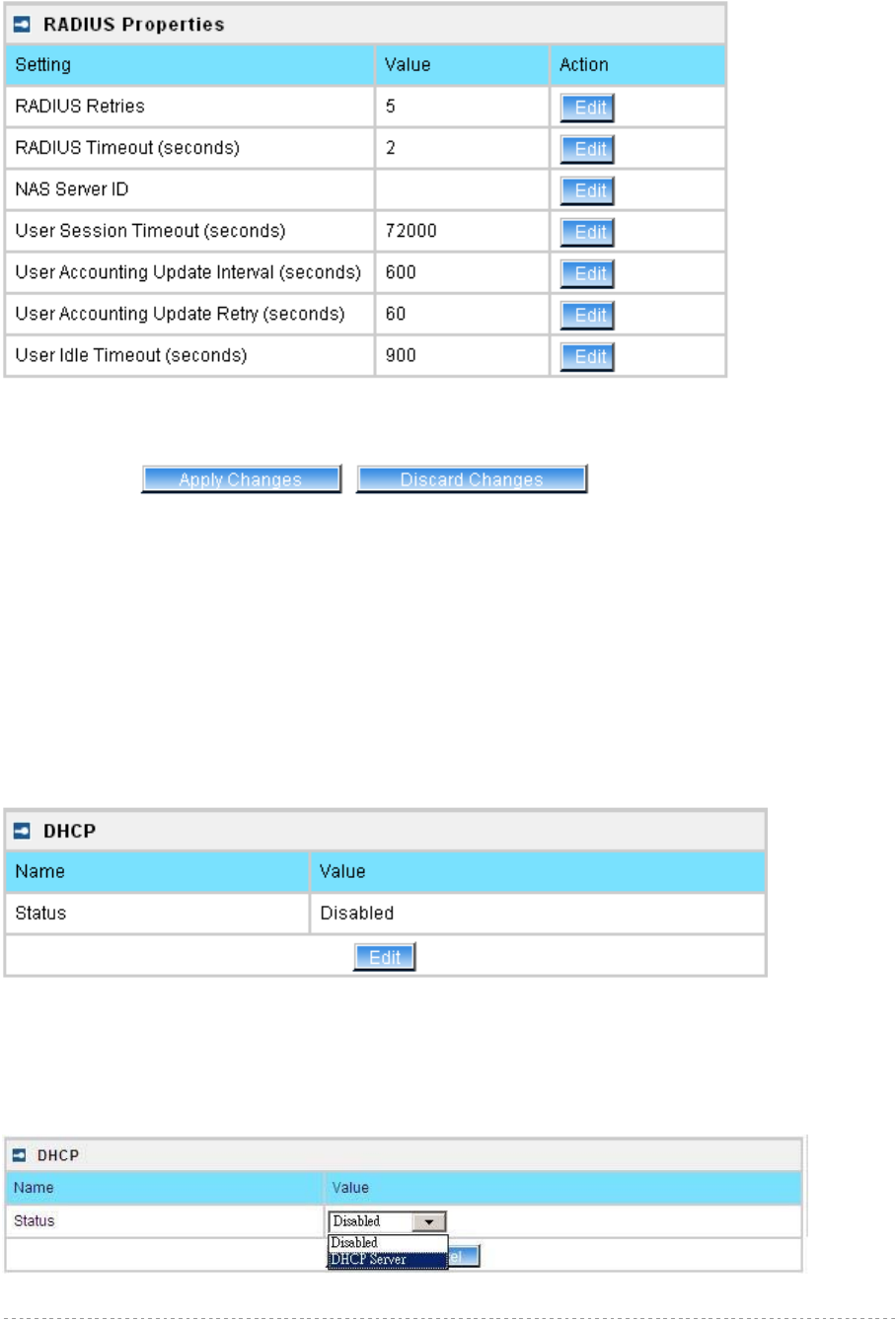
Use the save button to save an entered value. Now select another RADIUS property to edit, or Apply
Changes and restart your AP if the configuration is finished:
Apply Changes – click if RADIUS Properties configuration is finished
Discard Changes – restore all previous values
Network | DHCP
In AP mode, BW1254 can act as DHCP server. The DHCP (Dynamic Host Configuration Protocol)
service is supported on layer 2 interfaces.
DHCP server and DHCP relay are disabled by default.
Figure 33 – DHCP Settings
Edit – edit the DHCP settings
To enable DHCP server click the Edit button.
Figure 34 – DHCP Settings
BW1254 User Guide v1.0 Nov. 2013
Page 29 of 184
Status – select status from the drop-down menu.
Disabled – disable the DHCP server service.
DHCP Server – enable the DHCP server service.
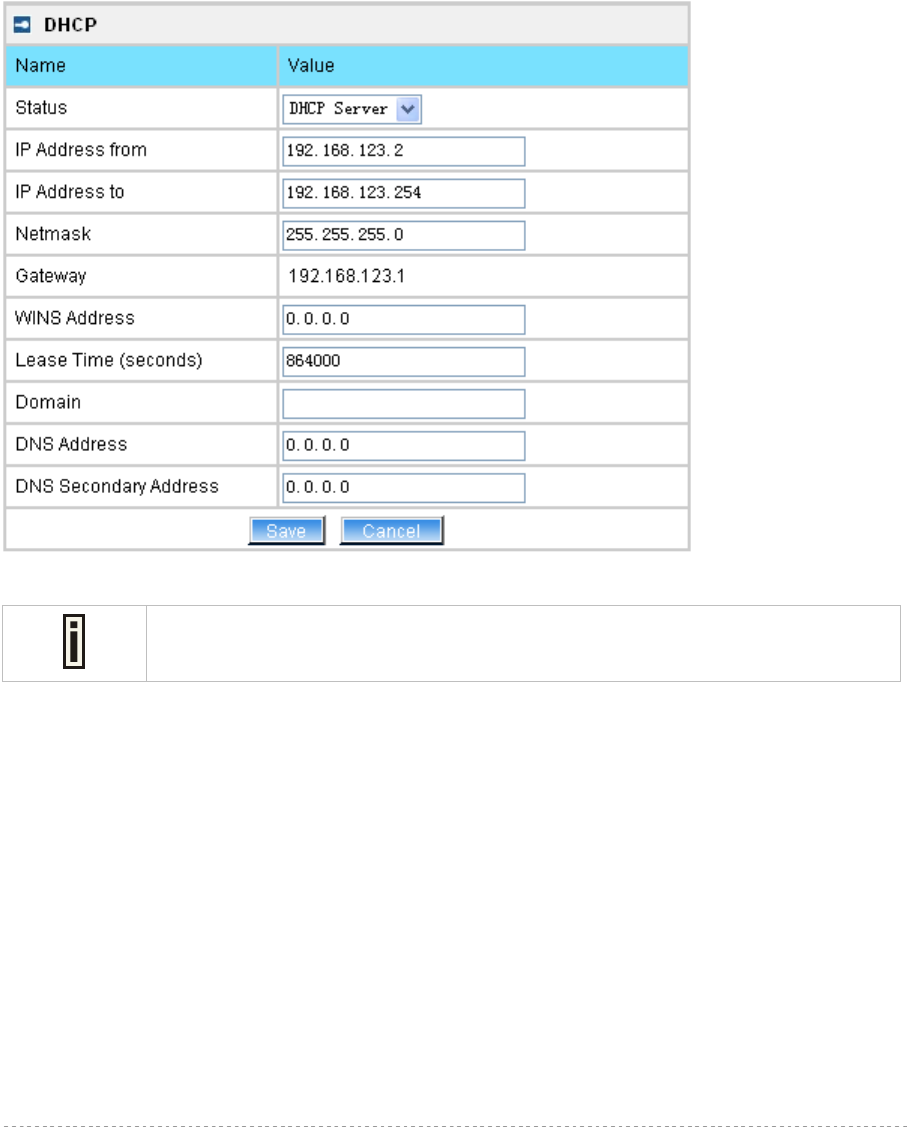
Choose DHCP Server to enable DHCP server service.
DHCP Server
This DHCP server service enables clients on the LAN to request configuration information, such as IP
address, from a server. Settings of the DHCP service can be viewed just like the follow page.
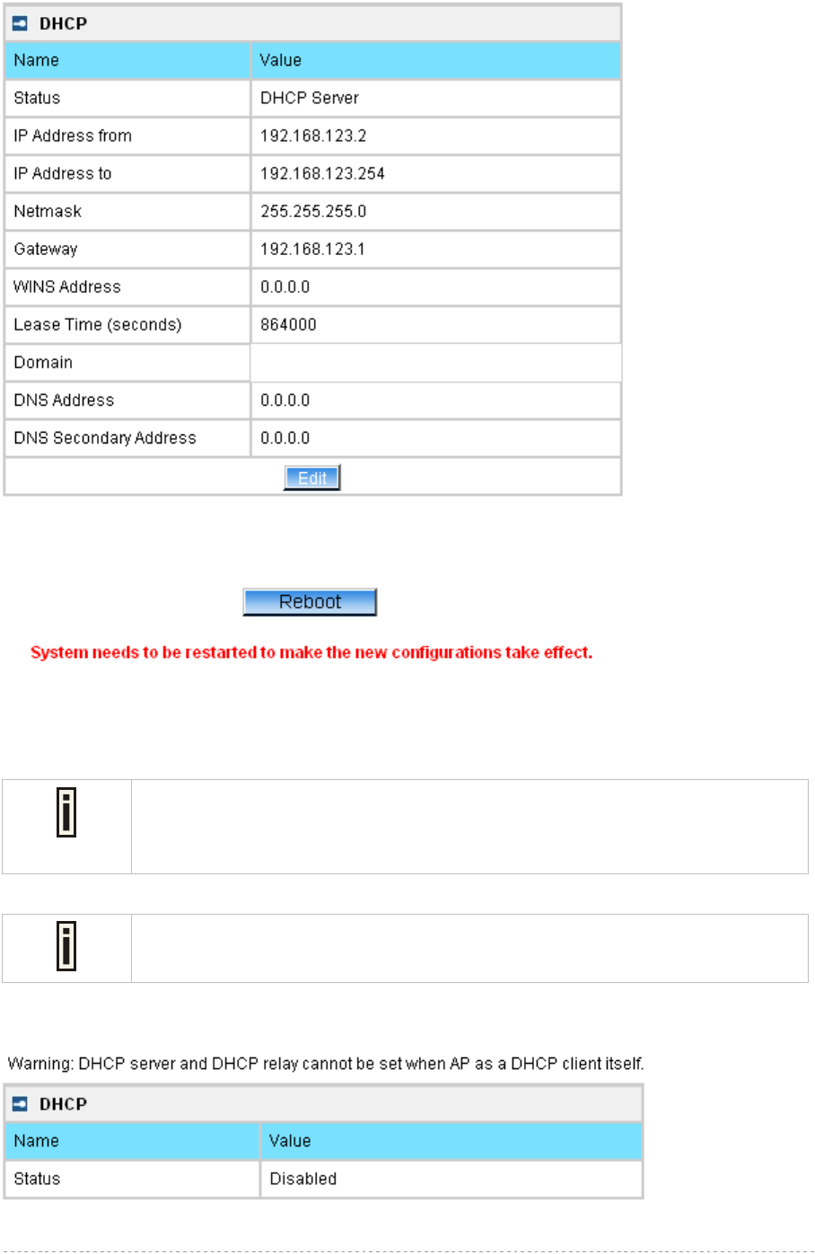
Figure 35 – DHCP server Settings
By default, DHCP server is disabled.
IP Address from / IP Address to – specify the IP address range to be dynamically allocated by the
DHCP server.
Netmask – enter the netmask for IP pool range.
Gateway – enter the gateway IP for wireless clients.
WINS Address (Windows Internet Naming Service) – specify server IP address if it is available on the
network [dots and digits].
Lease Time – specify the IP address lease interval in seconds [1-1000000].
Domain – specify the DHCP domain name [optional, 1-128 sting].
DNS address – specify the DNS server’s IP address [in digits and dots notation].
DNS secondary address – specify the secondary DNS server’s IP address [in digits and dots
notation].
Change status or leave in the default state if no editing is necessary and click the Save button.
BW1254 User Guide v1.0 Nov. 2013
Page 30 of 184
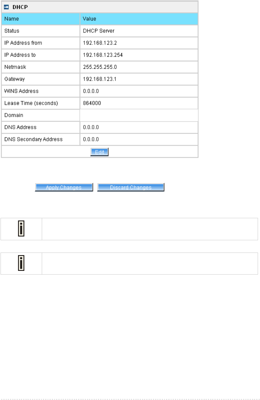
Figure 36 – Apply or Discard DHCP server Settings
The DHCP server settings will be automatically adjusted to match the network
interface settings.
The Gateway of DHCP server settings must be same with the Gateway of BW1254
For each change of settings, the BW1254 needs to be restarted to apply all settings changes when
clicking Apply Changes. Request for reboot server appears:
BW1254 User Guide v1.0 Nov. 2013
Page 31 of 184
Figure 37 – Reboot information
Reboot – click the button to restart the server and apply the changes.
If there is no other setting needed to be modified, click the Reboot button for
applying all modifications.
And if there are still other setting modifications needed, go ahead to finish all
changes and then click Reboot button to restart and apply all settings together.
When BW1254 network Interface uses DHCP to get IP address dynamically, DHCP
server service cannot be enabled.
When BW1254 uses DHCP to get IP address, the similar WEB UI will be appeared:
Figure 38 – Warning information
BW1254 User Guide v1.0 Nov. 2013
Page 32 of 184
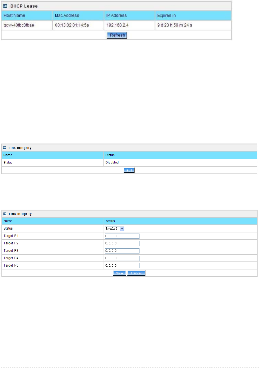
Network | DHCP Lease
This page display the DHCP lease information of wireless client which connect to the AP when DHCP
server enable.
Figure 39 – DHCP lease information
Host Name – the host name of wireless client which associate to the access point.
Mac Address –the MAC address of wireless client which associate to the access point.
IP Address –the IP address of wireless client which associate to the access point.
Expires in – expire time of the wireless client which associate to the access point.
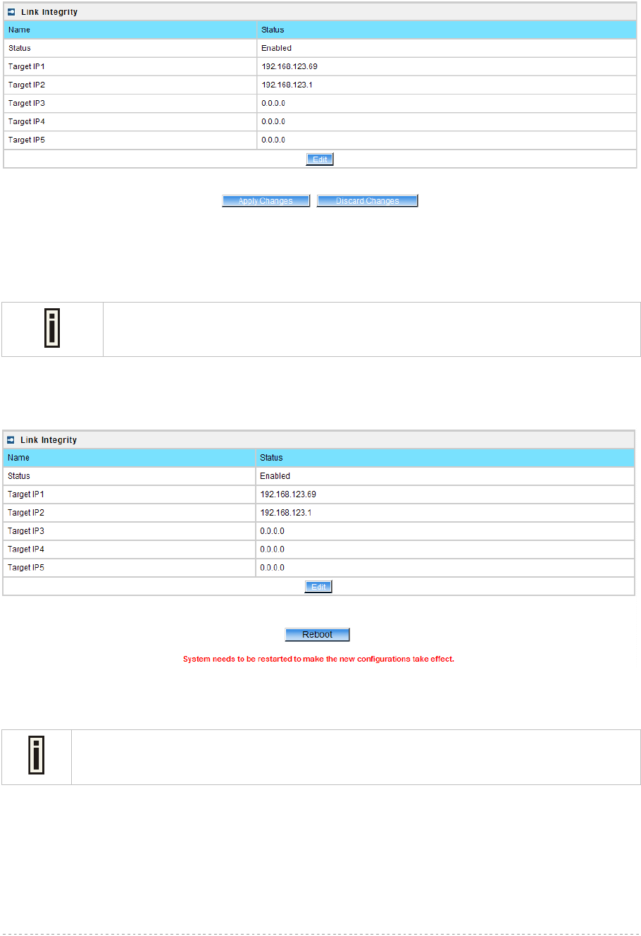
Network | Link Integrity
Specify Link Integrity feature’s settings here. Enable Link Integrity, BW1254 will close wireless
connections and kick out all the wireless clients when it detects that its Ethernet network cannot be
accessed to the internet.
Figure 40 – Link Integrity settings
Click Edit button to set the Link Integrity settings, the similar UI will be appeared as below:
Figure 41 – Edit Link Integrity settings
Status – Enable or disable the feature of Link Integrity
Target IP1 to Target IP5 – IP addresses for BW1254 detecting if its Ethernet interface can access
network. The AP will ping every IP address 15 times in sequence. As long as one ping is successful it
will consider the network is no problem. If ping fail for all IP address specified it will consider Ethernet
link fail and all associated wireless client will be logged out. The AP will continue to ping from first IP
address. If ping success the wireless client will access AP again.
Save – save the entered values.
BW1254 User Guide v1.0 Nov. 2013
Page 33 of 184
Cancel – restore all previous values.
Click Save, the similar apply changes UI will be appeared:
Figure 42 –Apply or Discard Link Integrity Settings
Apply Changes – save all changes in the interface table at once.
Discard Changes – restore all previous values.
Maximum 5 target IP can be specified.
The BW1254 needs to be restarted to apply all settings changes when clicking Apply Changes.
Request for reboot server appears:
Figure 43 – Reboot Server
Reboot – click the button to restart the server and apply the changes.
If there is no other settings needed to be modified, click the Reboot button to apply all
changes. If there are any other settings need to be changed, continuously to finish and
apply all changes and then click Reboot button to restart and take effect for all settings.
BW1254 User Guide v1.0 Nov. 2013
Page 34 of 184
Network | WAPI Certificate Upload
WLAN Authentication and Privacy Infrastructure (WAPI) is a Chinese National Standard for Wireless
LANs (GB 15629.11-2003), which was initiated to resolve the existing security loopholes (WEP) in
WLAN international standard (ISO/IEC 8802-11). WAPI works by having a central Authentication Service
Unit (ASU) which is known to both the wireless user and the access point and which acts as a central
authority verifying both. The WAPI standard (draft JTC1/SC6/N14619) allows selection of the symmetric
encryption algorithm, either AES or SMS4, which has been declassified in January 2006 and passed
evaluation by independent experts.
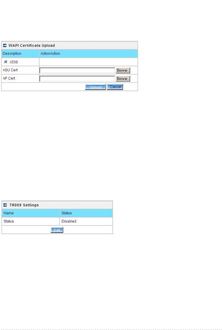
Figure 44 – WAPI certification upload
ASU Cert – uploading the ASU certification
AP Cert – uploading the AP certification
Network | Tr069 Settings
TR-069 is the Broadband Forum technical specification entitled CPE WAN Management
Protocol(CWMP). It defines an application layer protocol for remote management of end-user devices.
As a bidirectional SOAP/HTTP-based protocol, it provides the communication between customer-
premises equipment(CPE) and Auto Configuration Servers(ACS server). It includes both a safe auto
configuration and the control of other CPE management functions within an integrated framework.
The protocol addressed the growing number of different internet access devices such as
modems,routers,gateways,set-top-boxes,and VOIP-phones for the end users. The TR-069 standard
was developed for automatic configuration of these devices with Auto Configuration Servers(ACS).
configure the remote management through TR069 ACS server(eg:BROWAN DMS server)
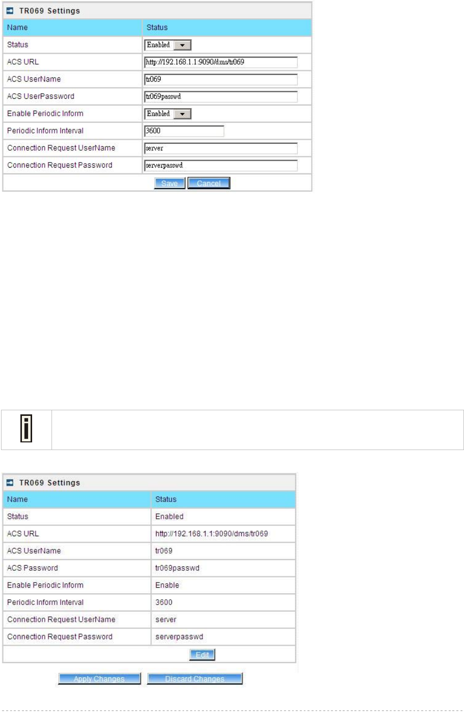
Figure 45 – TR-069 settings
Click Edit button and the similar page will be appeared.
BW1254 User Guide v1.0 Nov. 2013
Page 35 of 184
Figure 46 – edit TR-069 settings
Status – enable or disable TR-069 setting.[enable/disable]
ACS URL – enter the ACS server URL.
ACS UserName – the user name for AP register to ACS server.
ACS UserPassword – the password for AP register to ACS server.
Enable Periodic Inform – when AP registered to the ACS server, it will automatically send inform
message such as S/N,OUI,manufacturer and product name to the ACS server through TR-069
protocol in a periodic time.
Periodic Inform Interval – the inform interval.[in seconds, the value is 720~4294967295]
Connection Request UserName – when the ACS pulling a task to AP/CPE such as firmware
upgrade/downgrade, AP need the user name to verify the task sending from ACS server.
Connection Request Password –when the ACS pulling a task to AP/CPE such as firmware
upgrade/downgrade, AP need the password to verify the task sending from ACS server.
Contact the ACS server administrator to get the user name and password for
Connection Request UserName and Connection Request Password otherwise the
AP will not accept the task pulling by ACS server.
After enter all field click save and apply changes button to take effect.
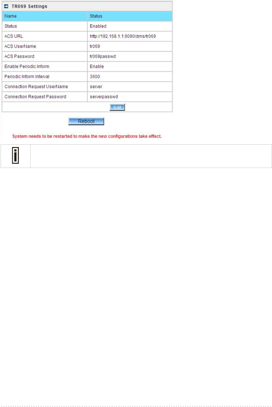
Figure 47 – save TR-069 settings
BW1254 User Guide v1.0 Nov. 2013
Page 36 of 184
Reboot – click the button to restart the server and apply the changes.
If there is no other settings needed to be modified, click the Reboot button to apply all
changes. If there are any other settings need to be changed, continuously to finish and
apply all changes and then click Reboot button to restart and take effect for all settings.
BW1254 User Guide v1.0 Nov. 2013
Page 37 of 184
Wireless
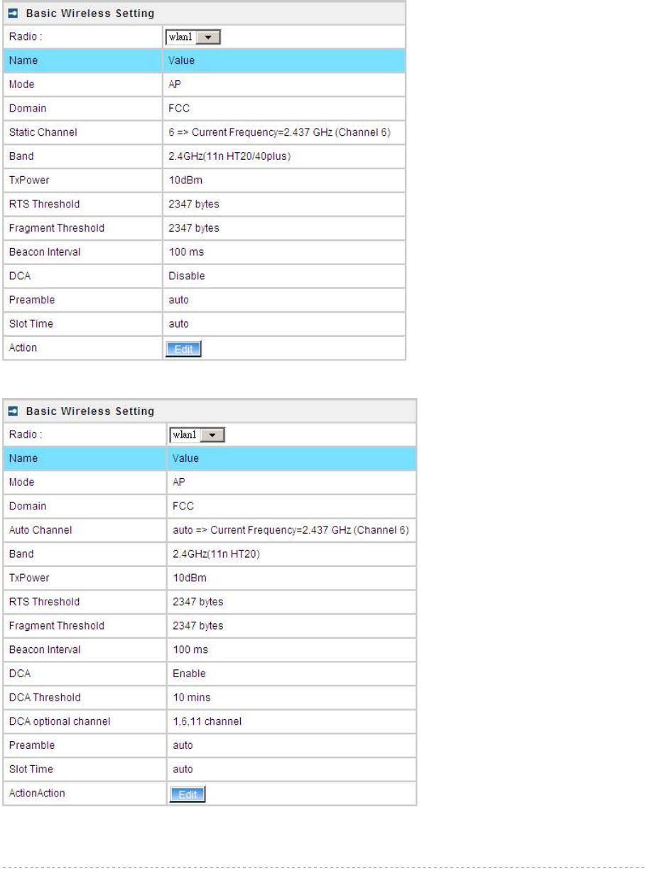
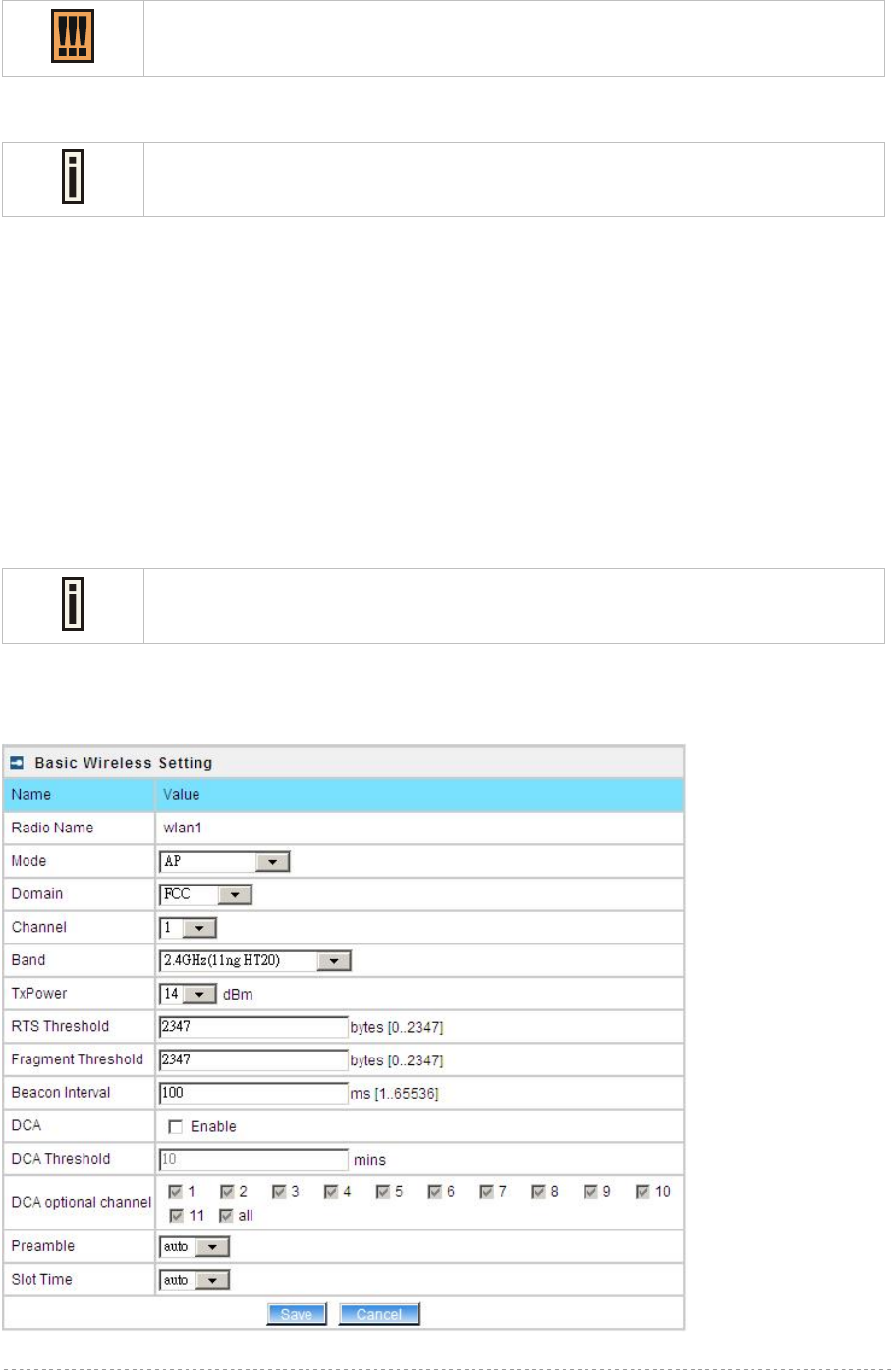
Wireless | Basic
Use the Wireless | Basic menu to configure wireless settings such as regulatory domain, channel,
band, and power, layer 2 isolation. Click the edit button on the setting you need to change:
Figure 48 – Basic Wireless Settings with static channel selection
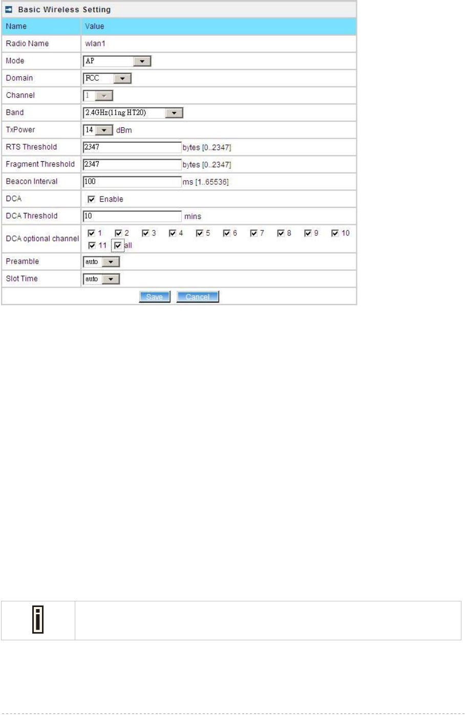
Figure 49 – Basic Wireless Settings with auto channel selection(DCA)
BW1254 User Guide v1.0 Nov. 2013
Page 38 of 184
Radio – specify which wireless interface of BW1254.[wlan1(2.4G)/wlan2(5G)]
Mode – show the radio operation mode. (AP mode or Bridge mode)
Domain – show the regulatory domain
Static Channel / Auto Channel – show the channel that the access point will use to transmit and
receive information
If DCA (Dynamic Channel Allocation) is enabled, this will show Auto Channel and
its channel number is chosen in auto channel selection.
If use static channel selection, this will show Static Channel and its channel
number.
DCA (Dynamic Channel Allocation) is useful feature to help choose the best
channel automatically and reduce interference among many Access Points.
Band – show the working bands on which the radio is working.
wlan1:four bands listed: 2.4GHz(11g only) , 2.4GHz(11n HT20) , 2.4GHz(11n HT20/40plus),
2.4GHz(11n HT20/40minus)
wlan2: four bands listed:5GHz(11a), 5GHz(11n HT20) , 5GHz(11n HT20/40plus), 5GHz(11n
HT20/40minus) .
By default, the HT20/40 is recommended.
Tx Power – show the BW1254 transmission output power (without antenna gain) in dBm.
RTS Threshold –the AP sends Request to Send(RTS) frames to a particular receiving station and
negotiates the sending of a data frame. After receiving an RTS, the wireless station responds with a
Clear to Send(CTS) frame to acknowledge the right to begin transmission. The default value is
2347.[recommend].
Fragment Threshold –It specifies the maximum size for a packet before data is fragmented into
multiple packets. If you experience a high packet error rate, you may slightly increase the
fragmentation threshold. Setting the fragmentation threshold too low may result in poor network
performance. Only minor modifications of this value are recommended. The default value is
2347.[recommend]
Beacon Interval –the Beacon Interval value indicates the frequency interval of the beacon. A beacon
is a packet broadcast by the AP to synchronize the wireless network.
DCA – Enable or Disable DCA service. DCA can help to choose the best working channel
automatically. And static channel selection will be forbidden if DCA is enabled.
DCA(Dynamic Channel Allocation) solution automatically select the optimal operational frequency
channel when power up and periodically monitors the environment and adjusts for the best
operational frequency channel.
DCA threshold – specify the value (in minutes) of DCA threshold. This threshold is been used to
judge if there is no wireless users connected during this time. And if yes, BW1254 will monitor the
environment and adjust channel for the best operational one.
If wireless network environment is stable which means auto channel selection
needn’t do frequently, set a big value for DCA threshold to gain a stable wireless
users’ connection.
If wireless network environment changes continually, frequent auto channel
selection is needed. So set a relative small value for DCA threshold to let channel
change based on wireless environment.
BW1254 User Guide v1.0 Nov. 2013
Page 39 of 184
Wireless users’ will be kicked off when DCA is processing (new operational
frequency channel takes effect).
DCA optional channel – show the channels only in which auto channel selection (DCA) will be
processed to reduce interference.
Only when DCA is enabled, DCA threshold and DCA optional channel will be
shown.
Preamble – if your wireless device supports the short preamble and you are having trouble getting it
to communicate with other 802.11b devices, make sure that it is set to use the long preamble.
Auto: using long preamble when there are clients not supporting short preamble connected ,
otherwise using short preamble. The default is Auto.[recommend]
Short: always using short preamble.
Long: always using long preamble.
Slot Time – show the slot time policy when working in 2.4GHz band.
Auto: using long slot time when there are clients not supporting short slot time connection,
otherwise using short slot time. The default is Auto.[recommend]
Short: always using short slot time.
Long: always using long slot time.
To Maximize the compatibility with some 11b clients, set both Preamble and Slot
Time to long.
Edit – edit the wireless basic settings
To change basic wireless setting properties click the Edit button in the Action column. The status
can be changed now:
Figure 50 – Edit Basic Wireless Settings with static channel selection
BW1254 User Guide v1.0 Nov. 2013
Page 40 of 184
Figure 51 – Edit Basic Wireless Settings with DCA enabled
Radio Name – specify wireless interface of BW1254 is shown
Mode – configure the radio operation mode. [AP mode or Dynamic Bridge mode]. There will be
different configuration for the two mode within Wireless | Advanced menu. Please refer to
corresponding chapter.
Selecting the AP Mode:
Domain – select the regulatory domain.
Channel – select the channel that the access point will use to transmit and receive information. If one
channel is defined, it acts as default channel. Channels list will vary depending on selected regulatory
domain and selected band. If you wish to operate more than one access point in overlapping
coverage areas, we recommend at least four channels interval between the chosen channels. For
example, for three Access Points in close proximity choose channels 1, 6 and 11 for 11b/g or
channels 36, 40 and 64 for 11a.
Band – show the working bands on which the radio is working.
wlan1:four bands listed: 2.4GHz(11g only) , 2.4GHz(11n HT20) , 2.4GHz(11n HT20/40plus),
2.4GHz(11n HT20/40minus)
wlan2: four bands listed:5GHz(11a), 5GHz(11n HT20) , 5GHz(11n HT20/40plus), 5GHz(11n
HT20/40minus) .
TxPower – the BW1254 transmission output power in dBm.
The value of the TxPower varies according to channel and regulatory domain.
RTS Threshold – the AP sends Request to Send(RTS) frames to a particular receiving station and
negotiates the sending of a data frame. After receiving an RTS, the wireless station responds with a
Clear to Send(CTS) frame to acknowledge the right to begin transmission. The default value is
2347.[recommend]

BW1254 User Guide v1.0 Nov. 2013
Page 41 of 184
Fragment Threshold – It specifies the maximum size for a packet before data is fragmented into
multiple packets. If you experience a high packet error rate, you may slightly increase the
fragmentation threshold. Setting the fragmentation threshold too low may result in poor network
performance. Only minor modifications of this value are recommended. The default value is
2347.[recommend]
Beacon Interval – the Beacon Interval value indicates the frequency interval of the beacon. A beacon
is a packet broadcast by the AP to synchronize the wireless network.
DCA – Enable or Disable DCA service. DCA can help to choose the best working channel
automatically. And static channel selection will be forbidden if DCA is enabled.
DCA(Dynamic Channel Allocation) solution automatically select the optimal operational frequency
channel when power up and periodically monitors the environment and adjusts for the best
operational frequency channel.
DCA threshold – specify the value (in minutes) of DCA threshold. This threshold is been used to
judge if there is no wireless users connected during this time. And if yes, BW1254 will monitor the
environment and adjust channel for the best operational one.
If wireless network environment is stable which means auto channel selection
needn’t do frequently, set a big value for DCA threshold to gain a stable wireless
users’ connection.
If wireless network environment changes continually, frequent auto channel
selection is needed. So set a relative small value for DCA threshold to let channel
change based on wireless environment.
Wireless users’ will be kicked off when DCA is processing (new operational
frequency channel takes effect).
DCA optional channel – specify the channels only in which auto channel selection (DCA) will choose
for reducing interference reference.
Only when DCA is enabled, DCA threshold and DCA optional channel will be
shown.
Preamble – if your wireless device supports the short preamble and you are having trouble getting it
to communicate with other 802.11b devices, make sure that it is set to use the long preamble.
Auto: using long preamble when there are clients not supporting short preamble connected ,
otherwise using short preamble. The default is Auto.[recommend]
Short: always using short preamble.
Long: always using long preamble.
Slot Time – specify the slot time policy when working in 2.4GHz band.
Auto: using long slot time when there are clients not supporting short slot time connected in,
otherwise using short slot time. The default is Auto.[recommend]
Short: always using short slot time.
Long: always using long slot time.
To Maximize the compatibility with some 11b clients, set both Preamble and Slot
Time to long.
BW1254 User Guide v1.0 Nov. 2013
Page 42 of 184
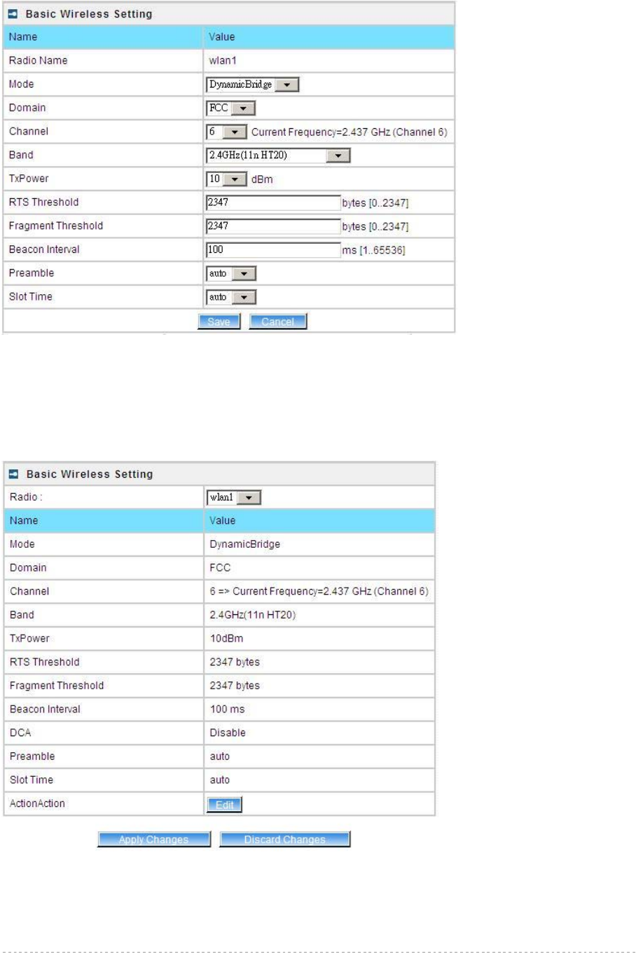
Configure the DynamicBridge Mode:
Figure 52 – Edit Basic Wireless Settings with DynamicBridge mode
All the parameters same with AP mode. For more detail with DynamicBridge setting please refer to
Wireless | Advanced page in DynamicBridge mode.
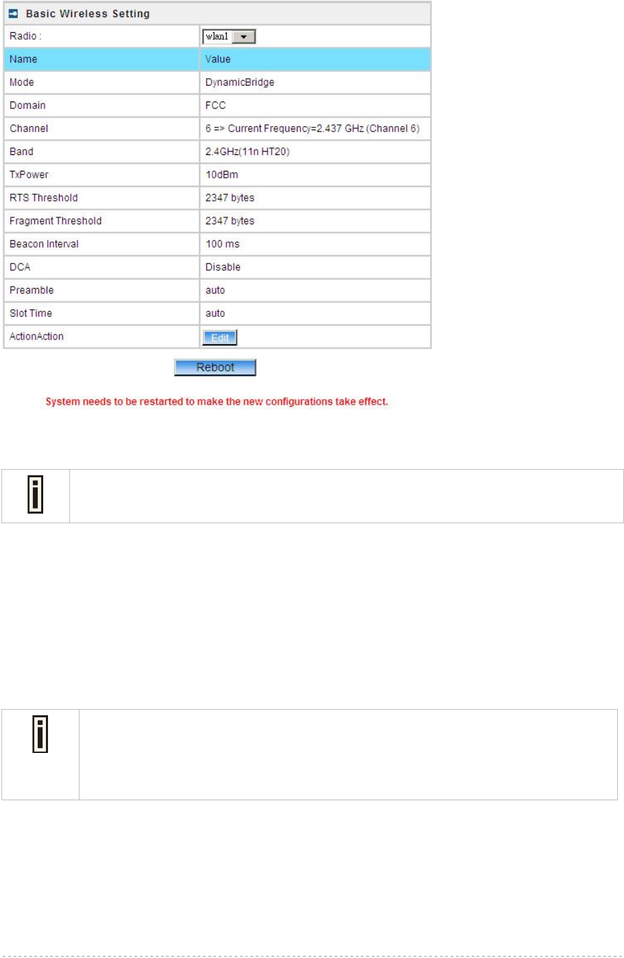
Change status or leave in the default state if no editing is necessary and click the Save button.
Figure 53 – Apply or Discard dynamicbridge setting
For such change of settings, the BW1254 needs to be restarted to apply all settings changes when
clicking Apply Changes. Request for reboot server appears:
BW1254 User Guide v1.0 Nov. 2013
Page 43 of 184
Figure 54 – Reboot Server
Reboot – click the button to restart the server and apply the changes.
If there is no other settings needed to be modified, click the Reboot button to apply all
changes. If there are any other settings need to be changed, continuously to finish and
apply all changes and then click Reboot button to restart and take effect for all settings.
Wireless | Advanced
BW1254 supports Multiple BSSID (MBSSID) function. You can configure up to 16 BSSIDs on
BW1254 and assign different configuration settings to each BSSID. For wireless users, they can think
BW1254 as single AP with multi-service supporting, including different security policy, different VLAN
ID, different authentication etc. All the BSSIDs are active at the same time that means client devices
can associate to the access point for specific service. Use the Wireless | Advanced menu to
configure properties related to Multiple BSSID, including configure SSID, Hidden SSID, VLAN, and
Security for each SSID.
You can define different MBSSID if you configure AP mode in Wireless | Basic menu.
Each BSSID can have its own SSID. In this case, Multiple BSSID is the same with
Multiple ESSID. Wireless users can think BW1254 as multiple virtual APs, each
supporting different service, and connects one SSID for the special services.
There are different setting within wireless | advanced menu based on AP mode or DynamicBridge
mode configured in Wireless | Basic menu.

BW1254 User Guide v1.0 Nov. 2013
Page 44 of 184
AP Mode
If you configure AP mode, the page will be shown as below in Wireless | Advanced menu.
Figure 55 – Advanced Wireless Setting (AP Mode)
Radio – specify wireless interface to be configured.[wlan1(2.4G/wlan2(5G)]
Mode – show the current operation mode of this radio (AP or Bridge mode)
Interface – display the interface which corresponding to the SSID. Each Interface maps to a BSSID
SSID – SSID name for wireless client searching and associating.
Hidden – show the status of Hidden SSID feature[disable/enable]
Security – show which security policy is used for this MBSSID entry
Current Connect # – show the number of current wireless clients associate to this MBSSID
New – create a new MBSSID entry
Detail – show the detail information of this MBSSID entry
Edit – edit the selected MBSSID entry you want to configure
Delete – delete the selected MBSSID entry. When in AP mode, you can not delete the last entry
Refresh – rescan the WEB page to get newer information
Clicking New or Edit button to configure the SSID parameters. Describe as below:

BW1254 User Guide v1.0 Nov. 2013
Page 45 of 184
Figure 56 – BSSID Setting -1
Radio – show the wireless interface is being configured.
Interface – show the current sub-interface.
Mode – show the operation mode of current radio.
SSID – a unique ID for your wireless network. It is case sensitive and must not exceed 32 characters.
The SSID is important for clients when connecting to the access point.
Need Hidden SSID – when enabled, the SSID of this Interface is invisible in the networks list
while scanning the available networks for wireless client (SSID is not broadcasted with its
Beacons). When disabled, the AP’s SSID is visible in the available network list
[enabled/disabled]. By default the Hidden SSID is disabled
SSID status – activated or deactivated the SSID. The default is activated SSID[check box].
Disable 11b – enable/disable 11b client connection. [check box] to enable the function.
Only 11n – only 802.11n client can connected to the SSID.
Disassociation low MCS – low MCS client won’t associate to the AP. [check box] to enable it.
Max Station Number – define maximum number of associated wireless client to this SSID. By default
the number is maximum 127 client can be associated to the AP without check box. Or check box to
enable limited client.[1~127]
Layer 2 Isolation – Specify the layer 2 isolation policy.
Enable Intra-BSS Layer 2 Isolation – when enabled, the clients that connect in this same BSS can’t
visit each other. By default the intra-BSS layer 2 isolation is disabled.
Intra-BSS layer2 isolation – which enable or disable client isolation under same SSID.
Inter-BSS layer2 isolation – which enable or disable client isolation between different
SSID.
Please go to Wireless | Layer 2 Isolation(Inter-BSS)
menu to configure inter-BSS layer 2 Isolation. Full layer 2 isolation need to set both
intra-BSS and inter-BSS layer 2 isolation in the AP mode.
Bandwidth – enable/disable upstream/downstream bandwidth control per SSID.
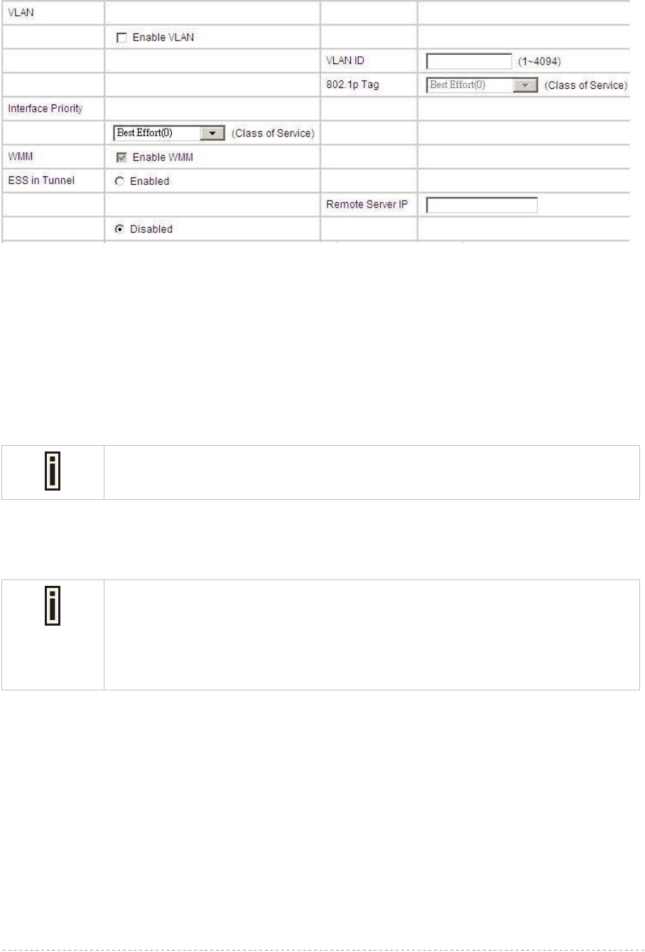
BW1254 User Guide v1.0 Nov. 2013
Page 46 of 184
Download bandwidth – specified the maximum downstream in Mbps controlled by the SSID.
Upload bandwidth – specify the maximum upstream in Mbps controlled by the SSID.
Figure 57 – Multiple BSSID Setting -2
VLAN – specify VLAN policy
Enable VLAN – when enabled, the outgoing packets from this SSID device will be tagged with
VLAN ID and 802.1p tag.
VLAN ID – configure VLAN ID for each Multiple SSID devices. Valid numbers are from 1 to
4094
802.1p Tag – configure 802.1p Tag for remote APC’s or Router’s QoS uses. Eight levels
selective, Background(1), Spare(2), Best Effort(0), Excellent Effort(3), Controlled Load(4),
Interactive Video(5), Interactive Voice(6), Network Contro(7)
VLAN ID and 802.1p tag must cooperate with remote Router or APC.
Interface priority – specify the traffic priority for this SSID interface, which is implemented according
to 802.11e EDCA and makes sure the wireless downlink QoS. This priority is based on SSID, which
means different BSSID can have different traffic priority and the traffic of the same SSID has the
same priority
This traffic priority only makes sure the priority of downlink (from AP to wireless
client).
8 levels priorities are supplied. 1, 2, 0, 3, 4, 5, 6, 7 is from lowest priority to highest
priority.
And if no special QoS is needed, leave priority to default (0). 0 means Best Effort
priority.
WMM –BW1254 support WMM wireless clients and implement WMM QoS with the WMM clients.
[enable]
ESS in Tunnel – Settings for ESS in tunnel. When enabled, BW1254 setup tunnel with remote AC for
passing through layer3 network.
Remote Server IP – IP address of remote AC product that setup tunnel with BW1254
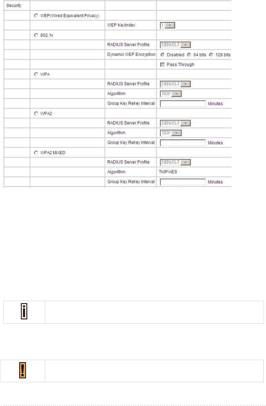
BW1254 User Guide v1.0 Nov. 2013
Page 47 of 184
Figure 58 – Multiple BSSID Setting – 3
Security – specify the security policy
WEP – Wired Equivalent Privacy(WEP) is a security algorithm for IEEE 802.11 wireless networks.
WEP Key Index – select the default key Index to make it the Default key and encrypt the
data before being transmitted. All stations, including this MSSID Entry, always transmit data
encrypted using this Default Key. The key number (1, 2, 3, 4) is also transmitted. The
receiving station will use the key number to determine which key to use for decryption. If the
key value does not match with the transmitting station, the decryption will fail. The key value
is set in Wireless | WEP web page
802.1x – when selected, the MSSID entry will be configured as an 802.1x authenticator. It
supports multiple authentication types based on EAP (Extensible Authentication Protocol) like
EAP-TLS, EAP-TTLS, EAP-PEAP, EAP-SIM. The privacy will be configured as dynamic WEP
RADIUS Server Profile – select your RADIUS server profile
Please go to Network | RADIUS Server menu to configure your RADIUS server
profile or add a new profile, and please refer to Network | RADIUS Server for its
configuration.
Dynamic WEP Encryption – select whether using the dynamic 64-bits encryption, 128-bits
encryption or without encryption
Pass Through – when enabled, client can access network whether it passed 802.1x
authentication or not
Only when 802.1x enabled and dynamic key disabled this option can be enabled.

BW1254 User Guide v1.0 Nov. 2013
Page 48 of 184
WPA – Wi-Fi Protected Access, When selected, the encrypt method will be WPA with RADIUS
Sever
WPA2 – when selected, the security policy will be WPA2 with RADIUS server. In this mode, WPA
client is not permitted to connect
WPA2 MIXED – when selected, WPA2 client and WPA client are all permitted to connect
RADIUS Server Profile – select your RADIUS server profile
Please go to Network | RADIUS Server menu to configure your RADIUS server
profile or add a new profile, and please refer to Network | RADIUS Server for its
configuration.
Algorithm – choose WPA algorithm (TKIP, AES)
Group Key Rekey Interval – specify amount of minutes and WPA automatically will generate a
new Group Key
Figure 59 – Multiple BSSID Setting – 4
WPA-PSK – when selected, the encrypt method will be WPA without RADIUS server
WPA2-PSK – when selected, the security policy will be WPA2 PSK without RADIUS server. In
this mode, only WPA2 PSK client can connect with AP and WPA PSK client is not permitted to
connect
WPA2-PSK MIXED – when selected, WPA2 PSK and WPA PSK clients are all permitted to
connect with AP
Use Pre-Shared Key –specify more than 8 characters and less than 64 characters for WPA
with pre-shared key encryption
Algorithm – choose WPA algorithm (TKIP, AES)
Group Key Rekey Interval –specify amount of minutes and WPA automatically will generate
a new Group Key
MAC Auth – when selected, the MAC address of wireless client will be passed to RADIUS server
for PAP authentication when it connects with BW1254. The MAC address of wireless client acts
as username and password
RADIUS Server Profile – select the default radius server name
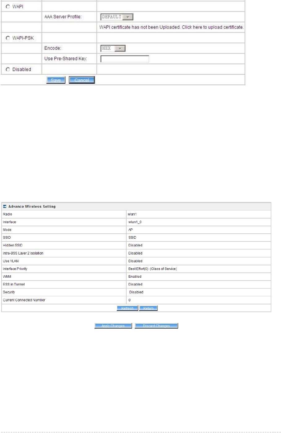
BW1254 User Guide v1.0 Nov. 2013
Page 49 of 184
Figure 60 – Multiple BSSID Setting – 5
WAPI – WLAN Authentication and Privacy Infrastructure (WAPI) is a Chinese National Standard for
wireless LAN(GB15629.11-2003).(Only for China)
It needs to upload WAPI certificate.
AAA Server Profile – select your RADIUS server profile
WAPI-PSK –the encrypt method will be WAPI without RADIUS server
Encode – Pre-shared key encode.[HEX/ASCII]
Use Pre-Shared key – specify more than 8 characters and less than 64 characters for WPA
with pre-shared key encryption
Disabled – when selected, you don’t select any security policy
Change status or leave in the default state if no editing is necessary and click the Save button.
Figure 61 –Apply or Discard the advanced Settings in AP mode
For each change of settings, the BW1254 needs to be restarted to apply all settings changes when
clicking Apply Changes. Request for reboot server appears:
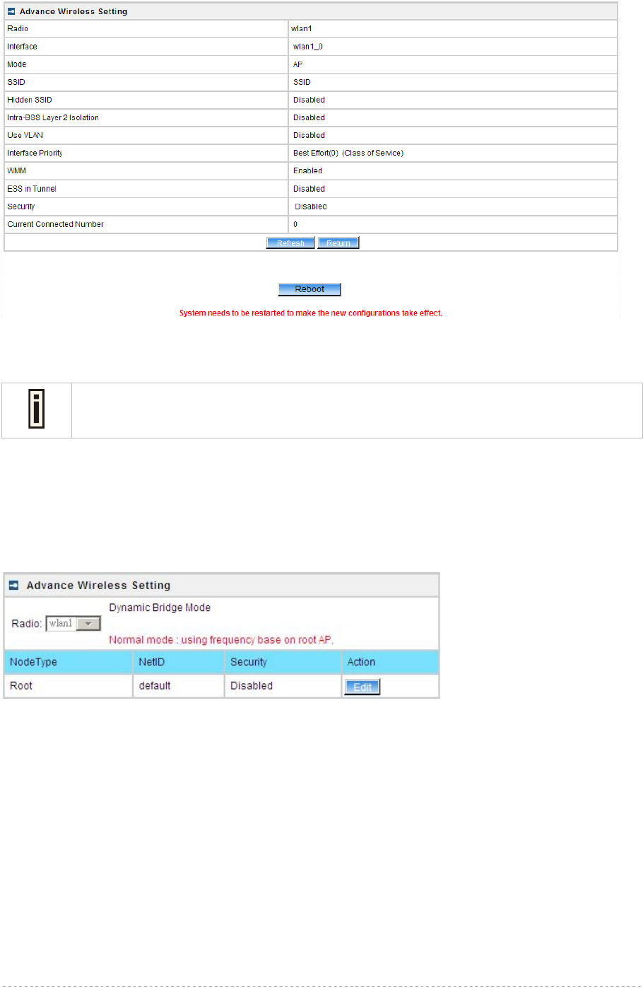
BW1254 User Guide v1.0 Nov. 2013
Page 50 of 184
Figure 62 – Reboot information
Reboot – click the button to restart the server and apply the changes.
If there is no other settings needed to be modified, click the Reboot button to apply all
changes. If there are any other settings need to be changed, continuously to finish and
apply all changes and then click Reboot button to restart and take effect for all settings.
DynamicBridge Mode
DynamicBridge is smart, high efficiency, high performance, easy deployment and easy configuration
for point to multi-point bridge link. It enables BW1254 to automatically seek and associate nearby root
AP and dynamically self-configure for wireless bridge connection. Whenever a bridge link is broken,
the network will auto re-configure route to minimize the lost of WLAN operation. It also minimized the
technician intervention and reduce cost of going on-site to re-establish transmission paths.
Figure 63 – Advanced Wireless Setting (Bridge Mode)
Radio – specify the wireless interface
NodeType – show the node type (root or normal)
NetID – Net ID for the association between root and normal(client) bridge link. It must be the same
between root and normal(client) association.
Security – specify which security policy is used
Edit – edit the selected Bridge link entry you want to configure
Clicking Edit to configure the bridge parameters.
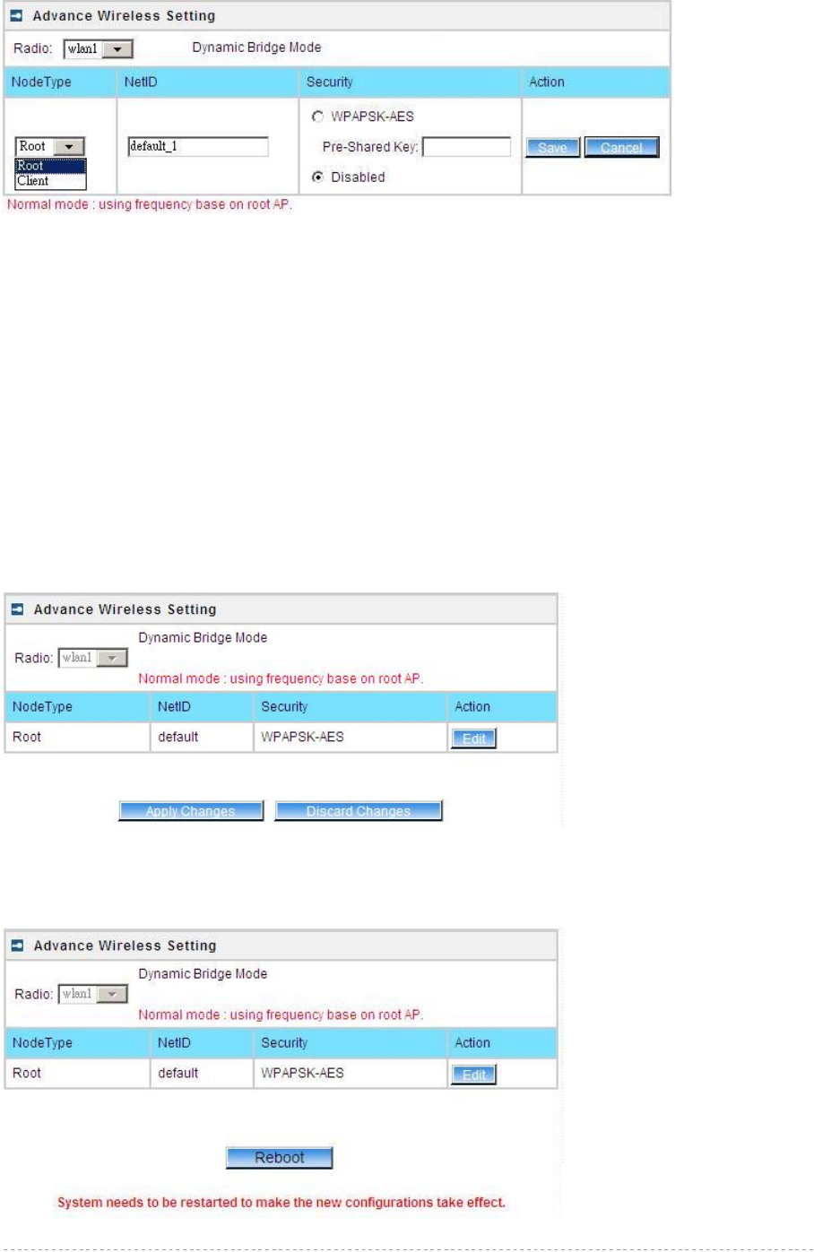
BW1254 User Guide v1.0 Nov. 2013
Page 51 of 184
Figure 64 – Bridge Link Setting
NodeType – determine the AP as Root or client rule. As a root AP, the nearby bridge client will
automatically associate to the root AP based on the signal quality. In case a bridge link is broken, the
client AP will automatically seek the nearby root AP based on the best signal quality and same NetID
to re-build a bridge link. For the client AP the NetID must same with root AP to distinguish which root
AP is in the link table. And the frequency channel is determined by the root AP despite the client AP
configured.
NetID – NetID is a very important element for the dynamicbridge link. The link between root and client
AP will based on the same NetID to make the bridge link.
Security – specify the security policy of the bridge link. [WPA-PSK (AES)/disable]
WPAPSK-AES –specify more than 8 characters and less than 64 characters for WPA with
pre-shared key encryption
Disable – no data encryption for the bridge link.
Click Save button to save the change of settings or Cancel button to discard the change
Figure 65 –Apply or Discard the advanced Settings in Bridge mode
For each change of settings, the BW1254 needs to be restarted to apply all settings changes when
clicking Apply Changes. Request for reboot server appears:
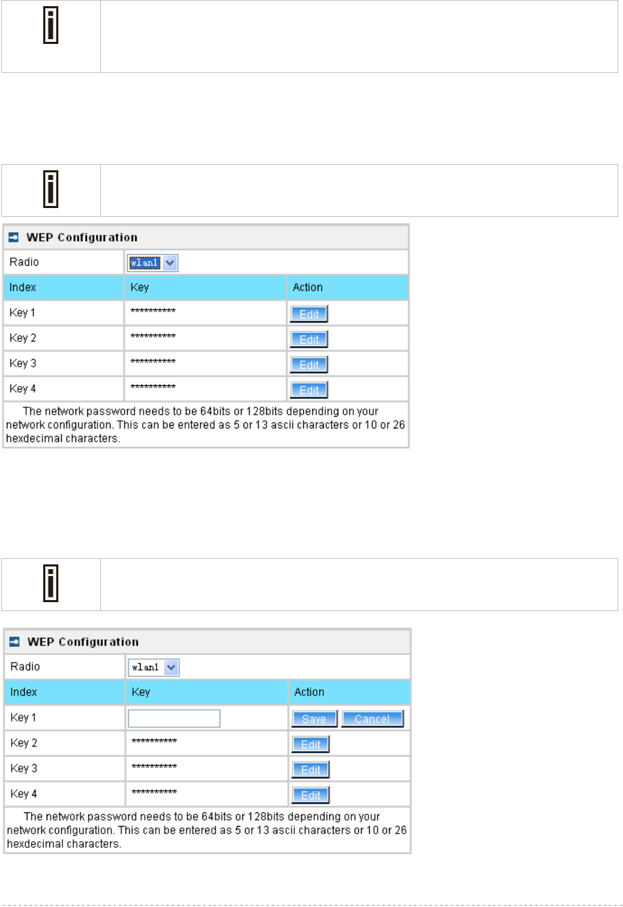
BW1254 User Guide v1.0 Nov. 2013
Page 52 of 184
Figure 66 – Reboot information
Reboot – click the button to restart the server and apply the changes.
If there is no other setting needed to be modified, click the Reboot button for
applying all modifications.
And if there are still other setting modifications needed, go ahead to finish all
changes and then click Reboot button to restart and apply all settings together.
Wireless | WEP
Use the Wireless | WEP menu to configure static WEP settings.
This menu only set static WEP key value related with 4 key indexes. Enable or
Disable static WEP is in the Wireless | Advance menu.
Figure 67 – WEP Settings
Radio –show the wireless interface.
Click Edit to edit the existing wepkey1 to wepkey4.
By default, four WEP keys are all set to “aaaaa” (ascii characters) or “6161616161”
(hexadecimal characters). They can be modified according to requirement.
Figure 68 – Edit WEP Key
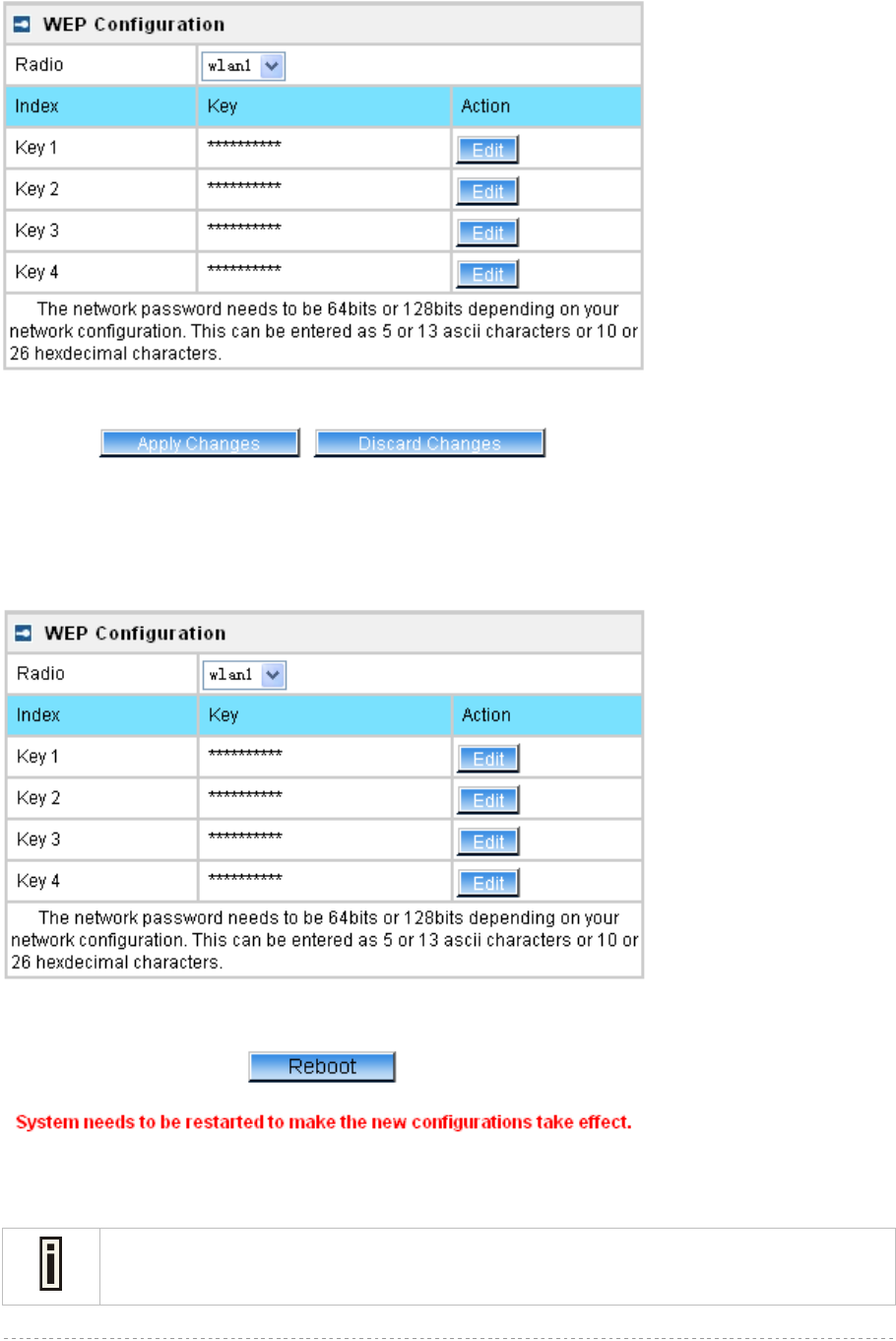
BW1254 User Guide v1.0 Nov. 2013
Page 53 of 184
Change status or leave in the default state if no editing is necessary and click the Save button.
Figure 69 –Apply or Discard WEP Configuration
For each change of settings, the BW1254 needs to be restarted to apply all settings changes when
clicking Apply Changes. Request for reboot server appears:
Figure 70 – Reboot information
Reboot – click the button to restart the server and apply the changes
If there is no other settings needed to be modified, click the Reboot button to apply all
changes. If there are any other settings need to be changed, continuously to finish and
apply all changes and then click Reboot button to restart and take effect for all settings.
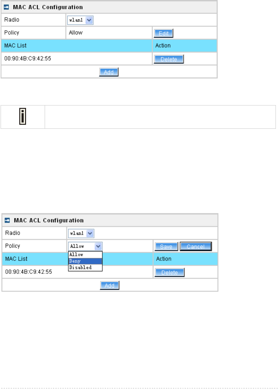
BW1254 User Guide v1.0 Nov. 2013
Page 54 of 184
Wireless | MAC ACL
Use the MAC ACL service to control the default access to the wireless interface of the BW1254 or
define special access rules for mobile clients. Configure the ACL using the Wireless | MAC ACL
menu:
Figure 71 – MAC ACL Service
Radio – show the wireless interface.
The wireless interface which is Bridge mode hasn’t MAC ACL settings.
Policy – click the edit button to choose Allow, Deny or disable the access control service on device.
By default the ACL service is disabled and all wireless clients connecting to the BW1254 are allowed
(no ACL rules are applied to the wireless clients)
Select Allow means only the wireless clients whose MAC are listed in the MAC List would be
permitted to access this AP. Other wireless client cannot access this AP.
Select Deny means only the wireless clients whose MAC are listed in the MAC List would be
prevented from accessing. Other wireless clients can access this AP.
Select Disabled means no ACL service.
Figure 72 – MAC ACL settings
You must create MAC List to work with Policy setting. The access control list is based on the
network device’s MAC address. In the MAC ACL Configuration table, you only need to specify the
MAC address of wireless client. Click the Add button to create a new MAC entry:
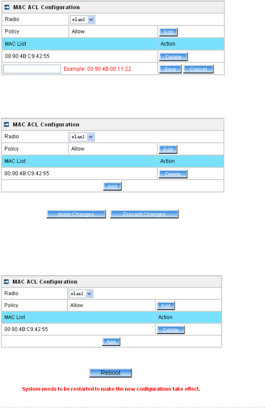
BW1254 User Guide v1.0 Nov. 2013
Page 55 of 184
Figure 73 – Add MAC entry
MAC Address – enter the physical address of the network device you need to (MAC address). The
format is a list of colon separated hexadecimal numbers (for example: 00:90:4B:00:11:22)
Save – click the button to save the new MAC entry
Figure 74 – Apply or Discard MAC ACL Configuration Changes
Apply Changes – to save all changes made in the interface table at once
Discard Changes – restore all previous values
For such change of settings, the BW1254 needs to be restarted to apply all settings changes when
clicking Apply Changes. Request for reboot server appears:
Figure 75 – Reboot Server
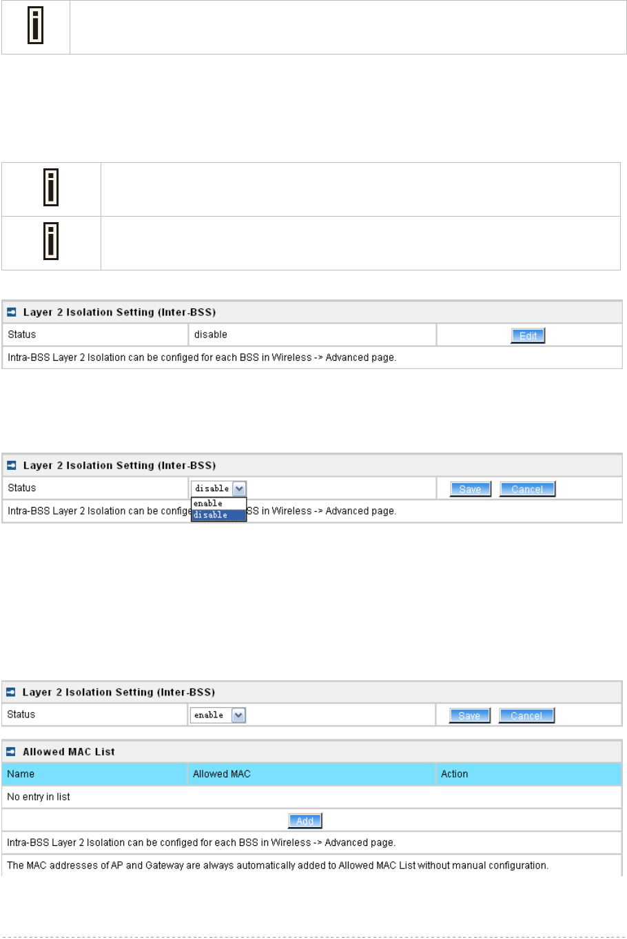
BW1254 User Guide v1.0 Nov. 2013
Page 56 of 184
Reboot – click the button to restart the server and apply the changes
If there is no other settings needed to be modified, click the Reboot button to apply all
changes. If there are any other settings need to be changed, continuously to finish and
apply all changes and then click Reboot button to restart and take effect for all settings.
Wireless | Layer 2 Isolation(Inter-BSS)
Use the Layer 2 Isolation service to block inter-BSS communication of all users. Users can only
access the AP connected, the gateway and devices in the allow MAC List.
Please go to Wireless | Advanced page to configure intra-BSS communication of
users in the same BSS. Full layer 2 isolation need to set both intra-BSS and inter-
BSS layer 2 isolation.
The Wireless | layer 2 isolation setting page is only exist in AP mode as it is only
for inter-BSS layer 2 isolation. There is no Wireless | layer 2 isolation setting page
in AP-Router mode.
Figure 76 – layer 2 Isolation Service
Edit – edit the layer 2 isolation settings.
To change layer 2 isolation setting properties click the Edit button.
Figure 77 – layer 2 Isolation Setting
Status –select status from the drop-down menu.
disable – disable the layer 2 isolation (Inter-BSS) service.
enable – enable the layer 2 isolation (Inter-BSS) service.
Only when Inter-BSS Isolation is enabled, the entry of the allowed MAC list can be added.
Figure 78 –Allowed MAC List
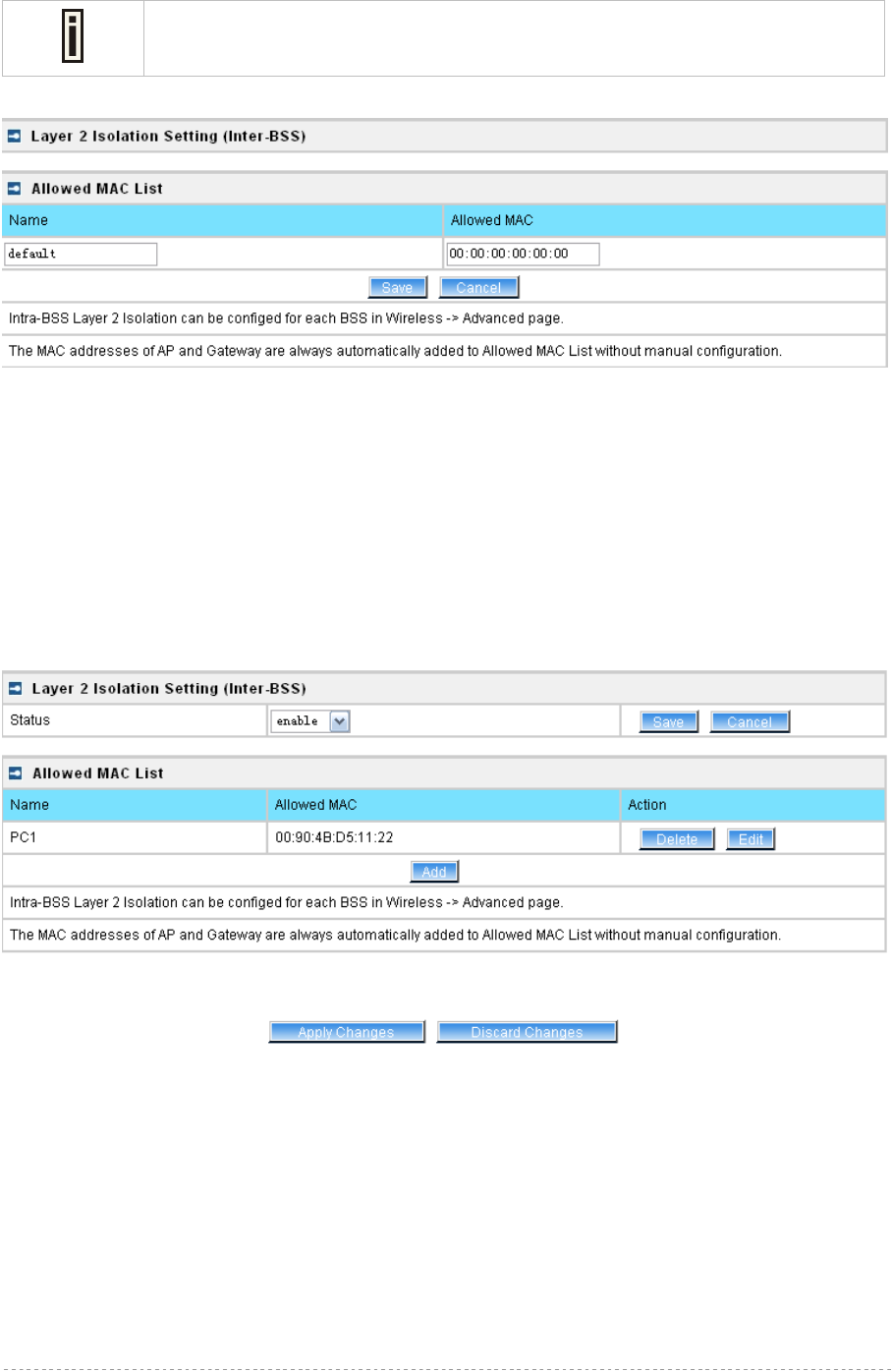
BW1254 User Guide v1.0 Nov. 2013
Page 57 of 184
The MAC addresses of AP and Gateway are always automatically added to
allowed MAC list without manual configuration.
Click the Add button to create a new MAC entry or click Edit button to edit the MAC entry:
Figure 79 –Add MAC entry
Name – the new Allowed MAC name, which length range is 1 to 32.
MAC Address – enter the physical address of the network device (MAC address). The format is a list
of colon separated hexadecimal numbers (for example: 00:90:4B:00:11:22)
Save – click the button to save the new Allowed MAC List entry
Cancel – discard change and restore all previous values
For such change of settings, the BW1254 needs to be restarted to apply all settings changes when
clicking Apply Changes. Request for reboot server appears:
Figure 80 –Save Allowed MAC List Changes
Apply Changes – save all changes
Discard Changes –restore all previous values
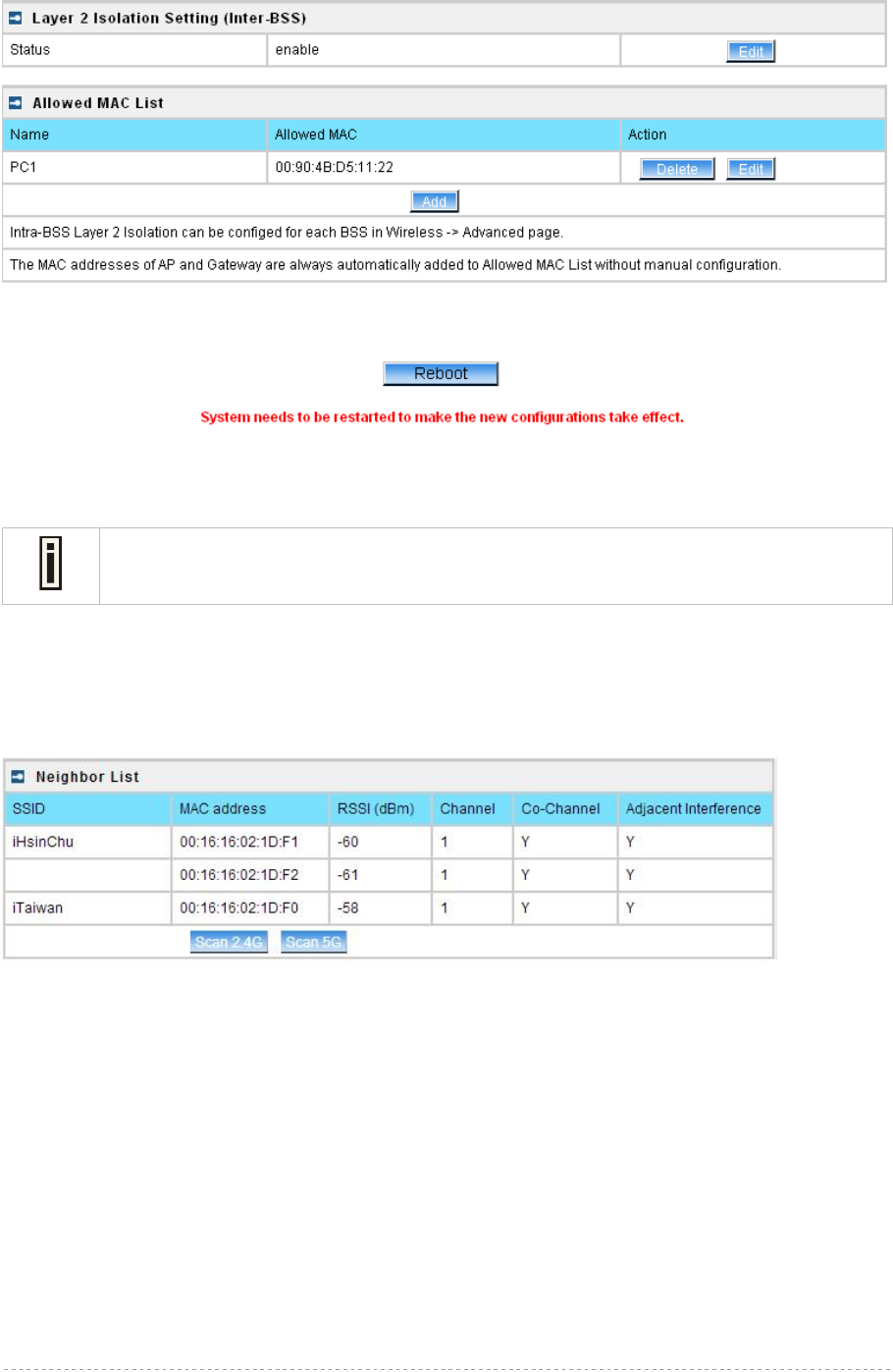
BW1254 User Guide v1.0 Nov. 2013
Page 58 of 184
Figure 81 –apply changes
Reboot – click the button to restart the server and apply the changes
If there is no other settings needed to be modified, click the Reboot button to apply all
changes. If there are any other settings need to be changed, continuously to finish and
apply all changes and then click Reboot button to restart and take effect for all settings.
Wireless | Neighbor List
The neighbor list will scan neighbor access point to show the RSSI, channel…etc information in the
environment.
Figure 82 – neighbor list
Click Scan 2.4G or Scan 5G button.
SSID – the SSID of scanned access point
MAC address – the MAC address of scanned access point
RSSI(dBm) – the RSSI of scanned access point(in dBm)
Channel –the channel of scanned access point
Co-Channel – display if the neighbor access point channel same with BW1254.[“Y”,yes/”N”,no]
Adjacent Interference –display the neighbor access point channel adjacent to BW1254.[“Y”,yes or
“N”,no]. It is based on the neighbor within 4 channels of BW1254. For instance, if BW1254 channel is
6 then the neighbor access point will be marked “Y” if its channel is 2,3,4,5 or 7,8,9,10.
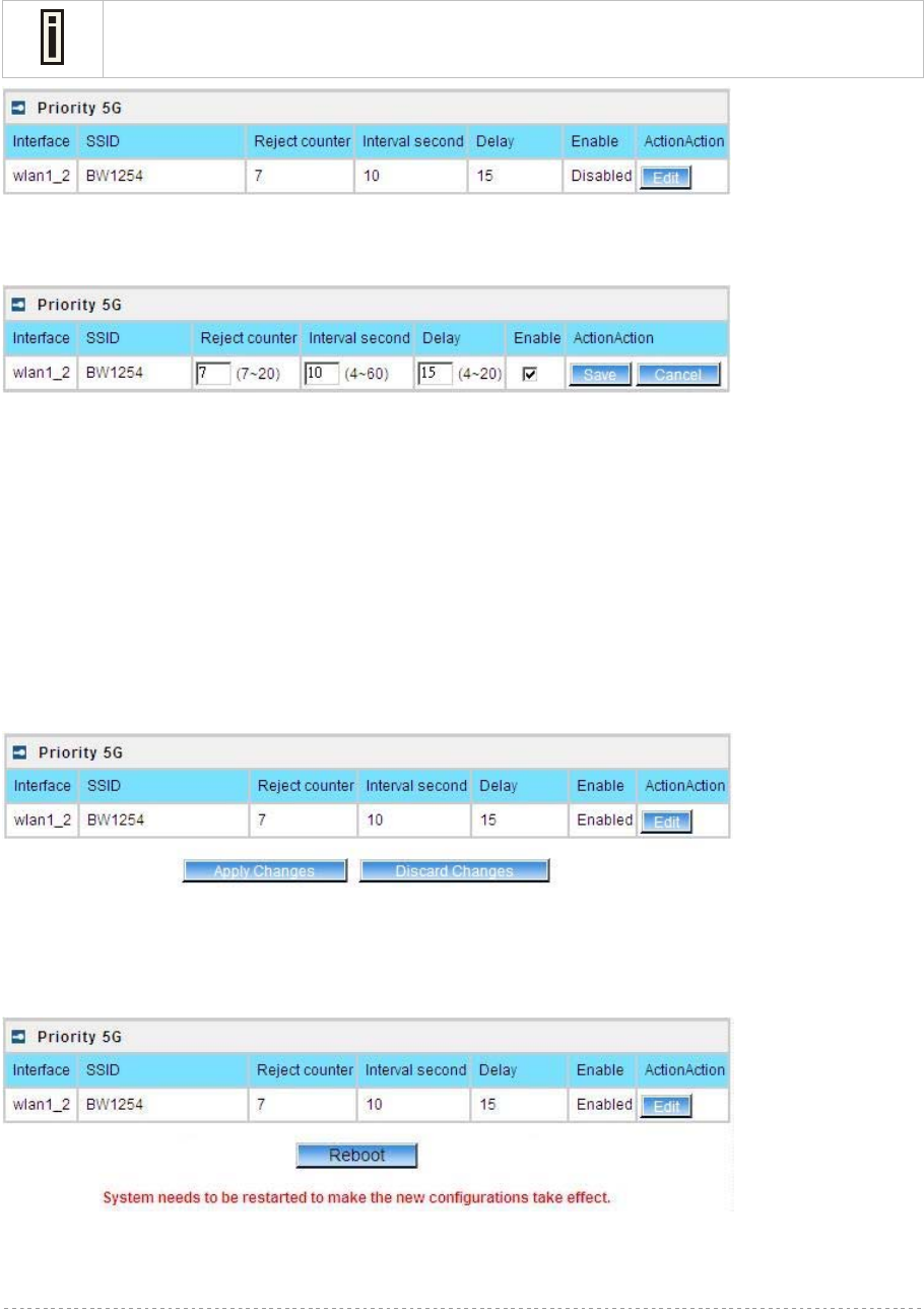
BW1254 User Guide v1.0 Nov. 2013
Page 59 of 184
Wireless | Priority 5G
The priority connection for dual band client. When the wlan1(2.4G) and wlan2(5G) configure same
SSID, the 5G frequency will prior to 2.4G connection if the client support dual band frequency.
Once WLAN1 and WLAN2 configure same SSID, the interface and SSID will display
automatically. Otherwise there will be nothing display in this page.
Figure 83 – priority 5G
Click Edit button to configure it.
Figure 84 – enable 5G priority
Interface – the interface of BW1254
SSID – the SSID of BW1254.[both 2.4G and 5G]
Reject counter – the counter that AP will reject 2.4G client connection
Interval second – the interval second during every reject counter
Delay – delay time of reject counter.
Enable – enable or disable the function.[check box or not]
Save/cancel – save/cancel configuration
Click apply changes or discard changes button to apply or discard the setting.
Figure 85 – apply/discard changes
Reboot device
Figure 86 – reboot device

BW1254 User Guide v1.0 Nov. 2013
Page 60 of 184
If there is no other settings needed to be modified, click the Reboot button to apply all
changes. If there are any other settings need to be changed, continuously to finish and
apply all changes and then click Reboot button to restart and take effect for all settings.

BW1254 User Guide v1.0 Nov. 2013
Page 61 of 184
User
User | Users
The User | Users menu shows the statistics of connected users. The user can be monitored and
managed such as drop from the network.
Figure 87 – User’s statistics
User – show the connected client’s MAC address
Interface – show which BSS the client connected to
User IP – IP address, from which the user’s connection is established [digits and dots]
Authed – indicate this client is authenticated or not
Wireless Auth – show the authentication method which user used to connect
Time Length – session duration since the user login [hh:mm:ss]
Idle Time – amount of user inactivity time [hh:mm:ss]
Action – view the statistics or kickoff the user.
Detail – click on user details to get more information about the client:
Kickoff – logout the user.
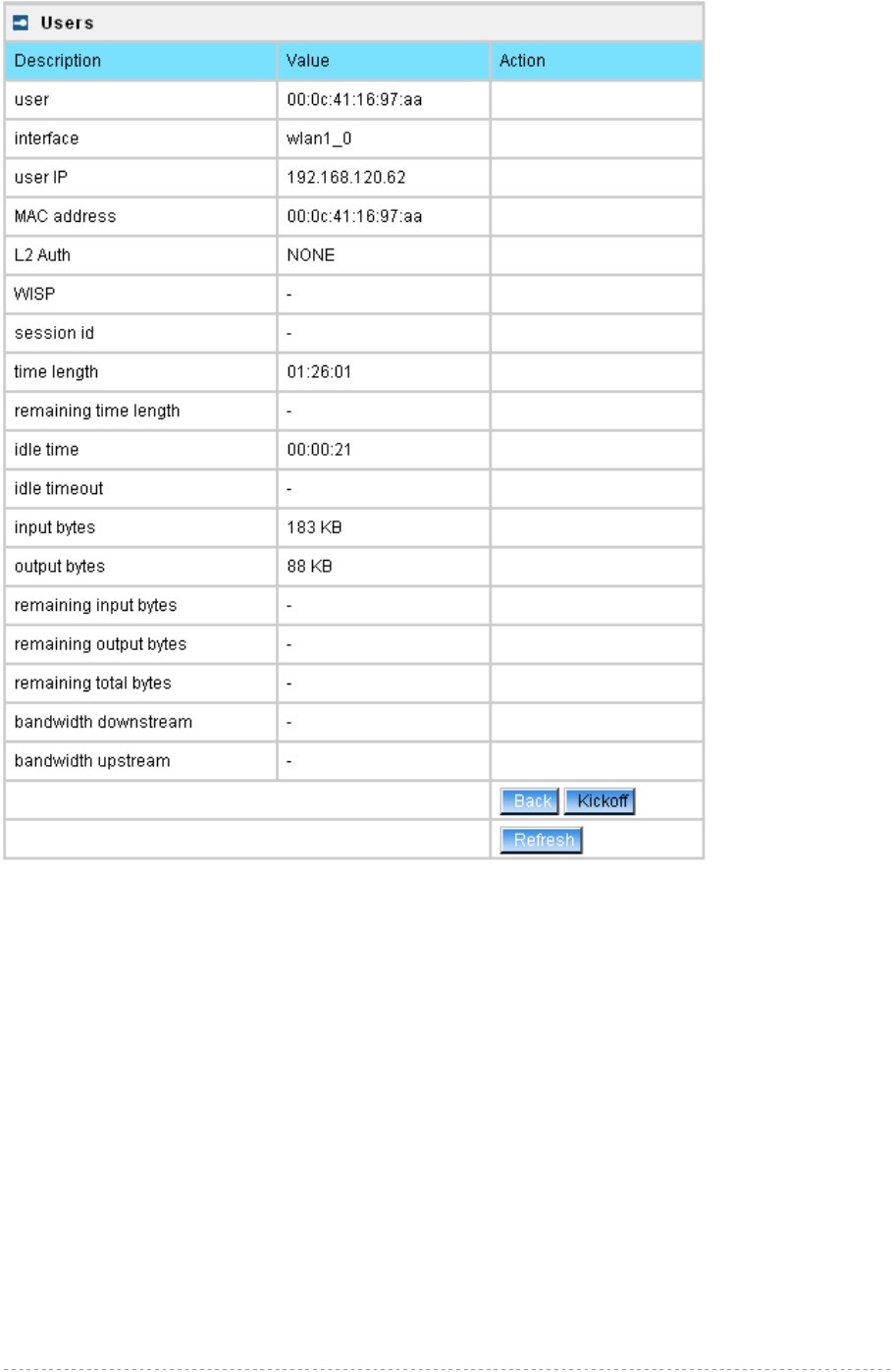
BW1254 User Guide v1.0 Nov. 2013
Page 62 of 184
Figure 88 – User’s Details
MAC address – hardware address of the network device from which the user is connected
L2 Auth – show layer2 authentication status, including all supported EAP type of 802.1x auth and
MAC auth
WISP – WISP domain name where the user belongs
Session ID – the unique user’s session ID number. This can be used for troubleshooting purposes
Remaining Time Length – remaining user’s session time [hh:mm:ss]. Session time for user is
defined in the RADIUS Server
Idle time – specify current idle time.
Idle Timeout – specify the time of user idle timout [hh:mm:ss]. When reach the time, the user will be
logged out automatically.
Input Bytes – amount of data in bytes which the user network device has received [Bytes]
Output Bytes – amount of data in bytes, transmitted by the user network device [Bytes]
Remaining Input/Output Bytes – user session remaining input/output bytes. WISPr Operator can
define the user session in bytes. Remaining bytes is received from RADIUS [Bytes/unlimited]
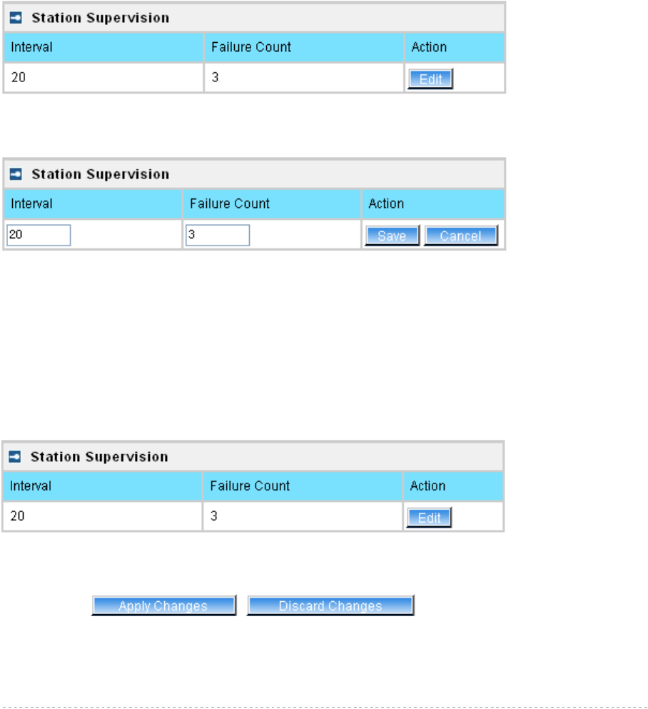
BW1254 User Guide v1.0 Nov. 2013
Page 63 of 184
Remaining Total Bytes –user session remaining total bytes. WISPr Operator can define the user
session in bytes. Remaining bytes is received from RADIUS [Bytes/unlimited]
Bandwidth Downstream/Upstream – user upstream and downstream bandwidth [in bps]
Back – returns to connect client’s statistics list
Kickoff –click this button to logout the user from access point.
Refresh – click the button to refresh users’ statistics
User | Station Supervision
The Station Supervision function is used to monitor the connected host station availability. This
monitoring is performed with ping. If the specified number of ping failures is reached (failure count),
the user is logged out from the BW1254.
Figure 89 – Station Supervision
To adjust the ping interval/failure count, click the Edit button.
Figure 90 – Edit Station Supervision
Interval – define interval of sending ping to host [in seconds]
Failure Count – failure count value after which the user is logged out from the system
Save – save station supervision settings
Cancel – cancel changes
Change status or leave in the default state if no editing is necessary and click the Save button.
Figure 91 –Apply or Discard Station Supervision Changes
Apply Changes – to save all changes made in the interface table at once
Discard Changes – restore all previous values
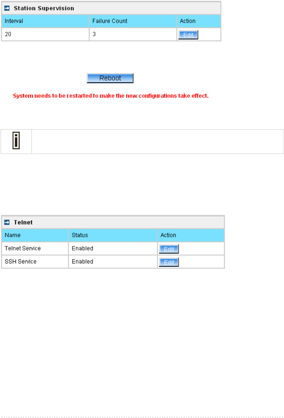
BW1254 User Guide v1.0 Nov. 2013
Page 64 of 184
For such change of settings, the BW1254 needs to be restarted to apply all settings changes when
clicking Apply Changes. Request for reboot server appears:
Figure 92 – Reboot Server
Reboot – click the button to restart the server and apply the changes
If there is no other settings needed to be modified, click the Reboot button to apply all
changes. If there are any other settings need to be changed, continuously to finish and
apply all changes and then click Reboot button to restart and take effect for all settings.
Services
Services | Telnet
Use Services | Telnet menu to manage the telnet/SSH service of your BW1254.
Figure 93 – System Configuration settings
Telnet Service – Enable or disable telnet service of BW1254
SSH Service – Enable or disable SSH service of BW1254
The default of these two services are all Enabled. The current IETF SSH (SSHv2) is supported for
security of accessing BW1254 via telnet/CLISH.
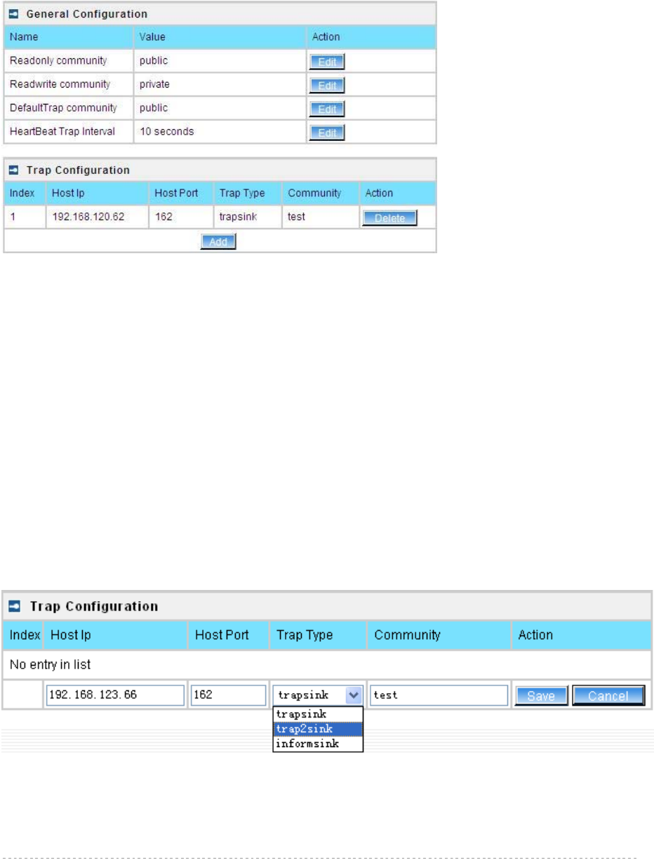
BW1254 User Guide v1.0 Nov. 2013
Page 65 of 184
Services | SNMP
SNMP is the standard protocol that regulates network management over the Internet. To
communicate with SNMP manager you must set up the same SNMP communities and identifiers on
both ends: manager and agent.
Use the Services | SNMP menu to change current SNMP configuration.
Figure 94 – SNMP settings
Readonly community – community name is used in SNMP version 1 and version 2c. Read-only
(public) community allows reading values, but denies any attempt to change values [1-32 all ASCII
printable characters, no spaces]
Readwrite community – community name is used in SNMP version 1 and version 2c. Read-write
(private) community allows to read and (where possible) change values [1-32 all ASCII printable
characters, no spaces]
Default Trap community – the default SNMP community name used for traps without specified
communities. The default community by most systems is "public". The community string must match
the community string used by the SNMP network management system (NMS) [1-32 all ASCII
printable characters, no spaces]
HeartBeat Trap Interval – defined the AP sending the trap interval to the SNMP server.[second]
Trap Configuration Table:
You can configure your SNMP agent to send SNMP Traps (and/or inform notifications) under the
defined host (SNMP manager) and community name (optional).
Click Add to add a new SNMP manager or Delete to delete a specific SNMP manager. Clicking Add:
Figure 95 – Add SNMP Trap
Host IP – enter SNMP manager IP address [dots and digits]
Host Port – enter the port number the trap messages should be send through [number]
Trap Type – select trap message type [v1/v2/inform]
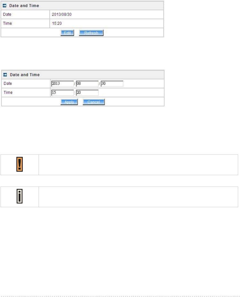
BW1254 User Guide v1.0 Nov. 2013
Page 66 of 184
Community – specify the community name at a SNMP trap message. This community will be used in
trap messages to authenticate the SNMP manager. If not defined, the default trap community name
will be used (specified in the SNMP table) [1-32 all ASCII printable characters, no spaces]
Save – save all current settings
Cancel – restore the last settings
Services | Time
Configure the system time manually under Services | Time Settings menu.
Figure 96 – Time Settings
Click Edit to change current system time.
Figure 97 – Edit Date and Time Settings
Date – [yy/mm/dd]
Time – [hour/minute]
Change the Date and Time or leave in the default value if no editing is necessary and click the Apply
button. Thus the modified time will be taken effect at once. No reboot is needed.
If NTP is enabled, the local time cannot be modified.
Since BW1254 hasn’t RTC (real-time clock), the system time will back to
1970/01/01 00:00 after reboot.
Services | NTP
NTP (Network Time Protocol) is used to synchronize the system time with the selected network NTP
server. Use the Services | NTP menu to configure the NTP service:
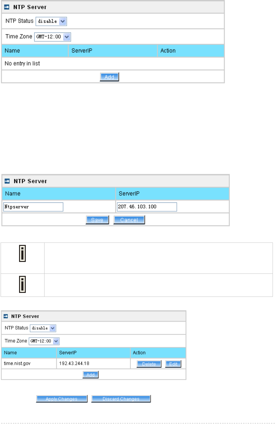
BW1254 User Guide v1.0 Nov. 2013
Page 67 of 184
Figure 98 – NTP Settings
NTP Status – specify enable or disable this NTP service
Time Zone – specify the time zone for NTP service
Delete – delete the existed NTP server
Edit – edit the settings of the existed NTP server
Add – add a new NTP server setting for synchronizing time
Clicking Add button to add a new NTP server:
Figure 99 – Add new NTP server setting
Two NTP servers can be configured under Services | NTP menu. And only IP
address is accepted for NTP server.
Adding at least one NTP server before enable NTP service.
The Name of NTP server should be unique.
Change status or leave in the default state if no editing is necessary and click the Save button.
Figure 100 – Save the NTP server Changes
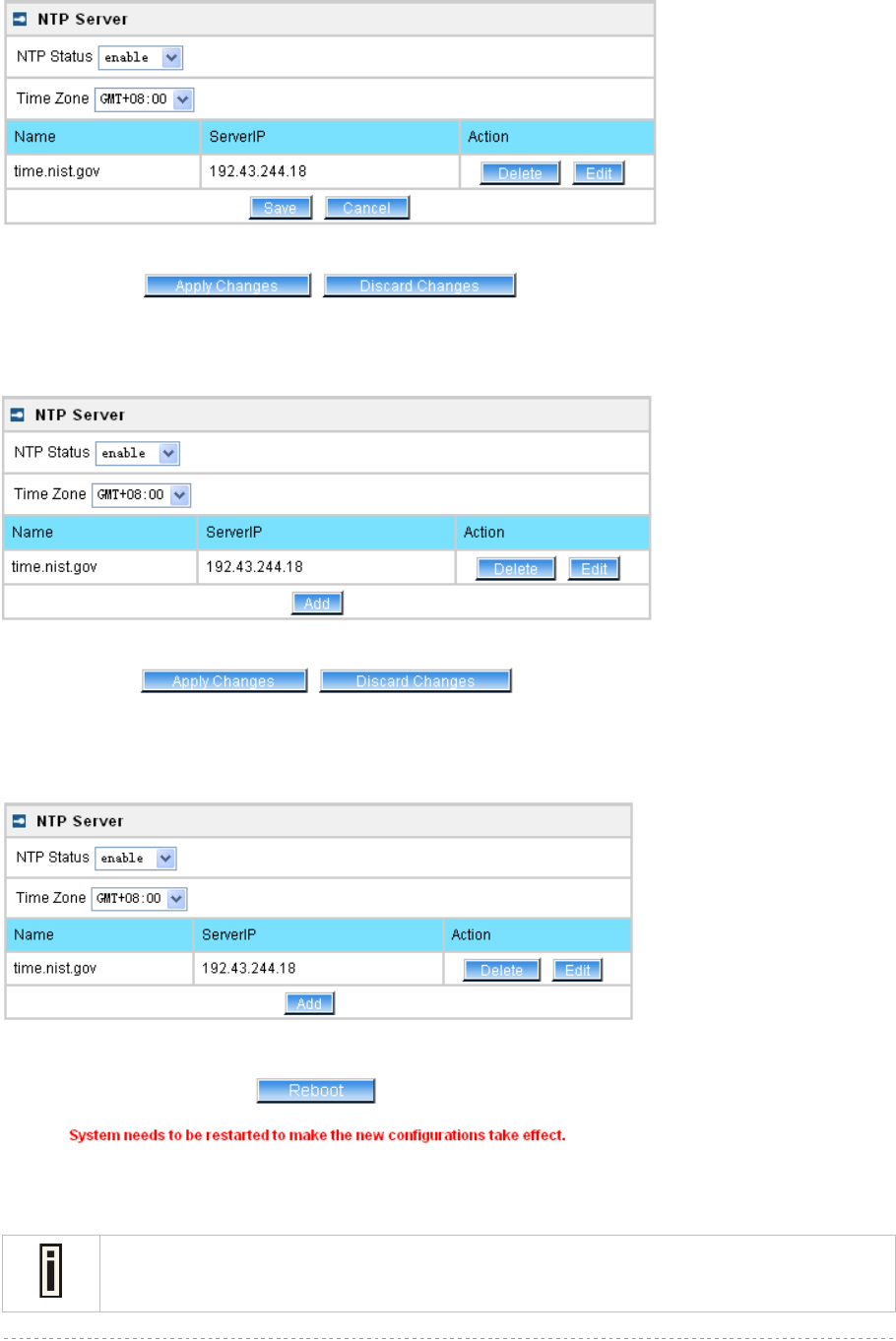
BW1254 User Guide v1.0 Nov. 2013
Page 68 of 184
Change the Time Zone for your own local time and change the NTP status to enable or disable.
Figure 101 – Edit Time Zone setting/NTP status
Click Save button to save new Time Zone setting.
Figure 102 – Apply or Discard Time Zone/NTP status Changes
For each change of settings, the BW1254 needs to be restarted to apply all settings changes when
clicking Apply Changes. Request for reboot server appears:
Figure 103 – Reboot information
Reboot – click the button to restart the server and apply the changes
If there is no other settings needed to be modified, click the Reboot button to apply all
changes. If there are any other settings need to be changed, continuously to finish and
apply all changes and then click Reboot button to restart and take effect for all settings.
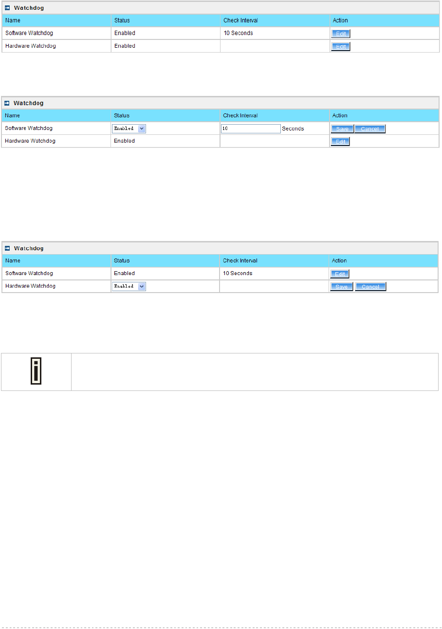
BW1254 User Guide v1.0 Nov. 2013
Page 69 of 184
Services | Watchdog
BW1254 supports watchdog function for the reliability. Use Services | Watchdog to enable/disable
watchdog service.
Figure 104 – Watchdog settings
Click Edit button to edit software watchdog settings. The UI will appear as below:
Figure 105 – edit Software Watchdog settings
Status – Enable or Disable software watchdog
Check Interval – the periodical time that software watchdog checks the whole file system of BW1254.
The hardware watchdog function will protect device even the operation system crash.
Figure 106 – edit hardware watchdog settings
Status – Enable or Disable hardware watchdog
The default value is enabled for both Software Watchdog and Hardware Watchdog.
It is strongly recommended to enable the watchdog function.
Click Save and follow the UI instruction to apply changes and reboot the device for apply all the
modified settings.
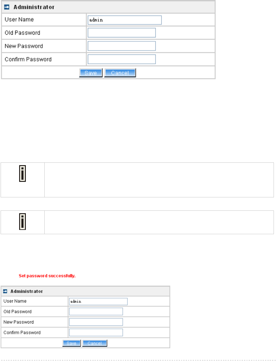
BW1254 User Guide v1.0 Nov. 2013
Page 70 of 184
System
System | Administrator
The System | Administrator menu is for changing the administrator’s settings: username and
password:
Figure 107 – system security settings
User Name – administrator username for access to BW1254 (e.g. web interface, CLI mode) [1-32
symbols, spaces not allowed]
Old Password – old password
New Password – new password value used for user authentication in the system [4-8 characters,
spaces not allowed]
Confirm Password – re-enter the new password to verify its accuracy
Save – click to save new administrator settings.
Default administrator logon settings are:
User Name: admin
Password: admin01
Password length is from 4 to 8 characters.
After filling in the right Old password and the New Password, clicking the Save button for taking effect
immediately.
After clicking Save button, the below UI will be shown to notify that the new password setting has
been taken place:
Figure 108 – system security settings save and take effect successfully

BW1254 User Guide v1.0 Nov. 2013
Page 71 of 184
System | System Log
Use the System | System Log menu to trace your AP system processes and get the system log
locally or on the remote log server.
Figure 109 – System Log settings
To enable the System Log remote sending function, click the Edit button on the Remote System Log
table and choose the enabled option:
Figure 110 – Configure Remote System Log Utility
Remote Log Status – choose disable/enable remote log function.[enabled/disabled]
Host IP – specify the host IP address where to send the System Log messages [dots and digits]
Log Level – specify the remote log message level you want to trace [critical, error, warning, info and
debug]
Do not output “debug” log unless there are important issue needs to be clarified.
Debug log will output all of the information so that it will severely drop down the
network performance.
BW1254 support standard sys. log server.
Save – save changes
Cancel – restore the previous values
To view the System Log locally, click the Edit button on the Local System Log table and choose the
enabled option:
Figure 111 –Configure Local System Log
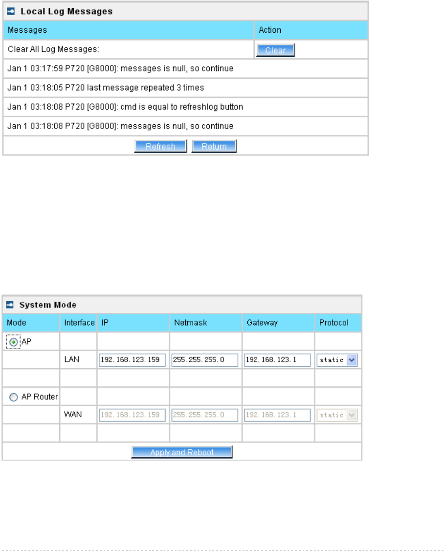
BW1254 User Guide v1.0 Nov. 2013
Page 72 of 184
Local Log Status – choose disable/enable local log [enabled/disabled]
Log Limit – specify the maximum length of local log message in byte [20000-512000]
Log Level – specify the local log message level you want to trace [critical, error, warning, info and
debug]
Save – save changes
Cancel – restore the previous values
View – view the log messages locally
Click View button, a similar screen will appear as below:
Figure 112 – View Local Log Messages
Clear – clear current log message
Refresh – get the updated log messages
Return – back to System Log page
System | System Mode
In this page, you can select the system mode of your BW1254.
Figure 113 – System Mode Settings
Mode – select whether the system mode of BW1254 is AP mode or AP Router mode
AP – The Ethernet interface and wireless interface will bridge into the same interface
working as transparent access point.
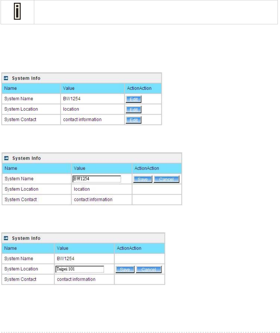
BW1254 User Guide v1.0 Nov. 2013
Page 73 of 184
AP Router – A wireless router is a device that performs the functions of a router but
also includes the functions of a wireless access point. Under this mode the Ethernet
will act as WAN interface and wireless interface will be act as LAN.
IP – specify the IP address of current interface [dots and digits]
Netmask – specify the subnet mask of current interface [dots and digits]
Gateway – specify the gateway to other networks
Protocol – specify static for setting IP address manually and dhcp for getting IP address dynamically
acting as DHCP client
Apply and Reboot – click the button to restart the device and apply all setting changes
The BW1254 Web Interface in AP mode is different from that in AP-Router mode. For
the detailed configuration of BW1254 working in AP-Router mode, please refer to the
next chapter: Chapter 4 – Reference Manual----AP-Router Mode
System | System Info
Administrator can self-define the device information including the system name, system location and
system contact information of his BW1254.
Figure 114 – System info Settings
System Name – edit the system name, the column length range is 1 to 255.
Figure 115 –edit the system name
System Location – edit the system location, the column length range is 1 to 255.
Figure 116 –edit the system location
System Contact – edit the system contact, the column length range is 1 to 255.

BW1254 User Guide v1.0 Nov. 2013
Page 74 of 184
Figure 117 –edit the system contact
Save – click the button to save the change.
Cancel – restore all previous values
System | Configuration
Use the System | Configuration menu to download current configuration or restore specified
configuration.
Configuration Backup – download current working system configuration for backup
Configuration Upload – upload system configuration for restore
Figure 118 – System Configuration settings
Click the Preparation button to start saving the configuration file.
Click the Download button to download current working configuration locally.
Figure 119 – Backup settings
By default the device configuration name is cfgbackup.cfg.
A configuration file name will be required when you download/save the
configuration file. And please remember or re-name the file if necessary. The
configuration file name should only include characters or numbers. Otherwise, this
configuration file will not upload to BW1254.

BW1254 User Guide v1.0 Nov. 2013
Page 75 of 184
You can upload saved configuration file any time you want to restore this configuration to the device
by using the Browse button. Select the configuration file and upload it on the device:
Figure 120 – Configuration Upload/Restore - 1
Click Upload for upload the specified configuration and then the similar UI appears
Figure 121 – Configuration Upload/Restore - 2
Click OK button to restore and AP will reboot immediately to take effect.
Figure 122 – Configuration Upload/Restore - 3
System | Reset and Reboot
Use this function to reboot device or restore to factory default.
Figure 123 – System Reset setting
Reboot – reboot the device
Reset – reset System to Factory Defaults
To reboot the device, click Reboot and then the below appears to make sure:
Figure 124 – Reboot the device
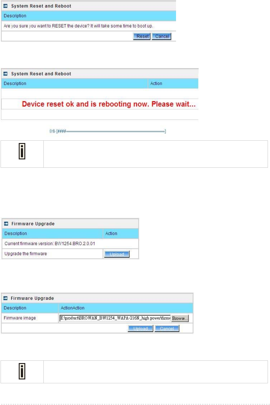
BW1254 User Guide v1.0 Nov. 2013
Page 76 of 184
To reset the device, click Reset and then the below appears to make sure:
Figure 125 – Reset the device
Click reset button the device will reset and reboot immediately to take effect.
Please note that all settings including the administrator settings will be set back to
the factory default when Reset is implement.
System | Local Upgrade
Upload – Update your device firmware locally.
Figure 126 – Firmware Upgrade
Click the Upload and then click the browse button to specify the full path of the new firmware image
and click the Upload button:
Figure 127 – Firmware Upgrade
Click the Upgrade button to flash and upgrade the firmware.
Please make sure the firmware is correct for BW1254. Otherwise the upgrade will
be failed.

BW1254 User Guide v1.0 Nov. 2013
Page 77 of 184
Figure 128 – upgrade firmware
Do not turn off the BW1254 during the firmware update process.
It will backward to previous version in case upgrade failure.
Update firmware will take about 4 minutes.
System | TFTP Upgrade
BW1254 support firmware upgrade via TFTP server.
Figure 129 – TFTP Firmware Upgrade
Current firmware version – Show the current firmware version.
TFTP server IP address - Specify the IP address of TFTP server which firmware located.
TFTP Time Out(Secs) – Specify the TFTP server communication time out in second.
Firmware Filename – Specify the upgrade firmware name to be download.
Figure 130 – TFTP Firmware Upgrade setting
Click “Edit” button to specify the TFTP server IP address,time out interval and firmware filename and
save the configuration then press “Download” button to download the firmware.
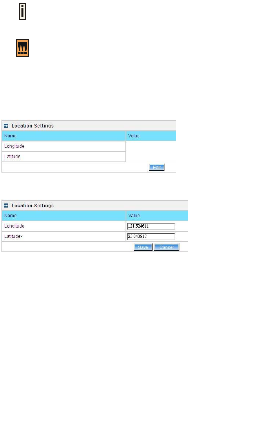
BW1254 User Guide v1.0 Nov. 2013
Page 78 of 184
Please make sure the firmware is correct for BW1254. Otherwise the upgrade will
be failed.
Do not turn off the BW1254 during the firmware update process.
It will backward to previous version in case upgrade failure.
System | Location Settings
You can define the longitude and latitude for the device information or for the NMS to locate the
device location.
Figure 131 – location setting
Click edit to enter the Longitude and Latitude in digit and dot format.
Figure 132 – edit location[longitude/latitude]
Click save button to save it.

BW1254 User Guide v1.0 Nov. 2013
Page 79 of 184
This chapter describes the configuration of the BW1254 which works in AP-Router mode using the
Web Interface.
The BW1254 Web Interface in AP-Router mode is different from that in AP mode. To
change your BW1254 to AP mode, please refer to System | System Mode . For the
detailed configuration of BW1254 working in AP mode, please refer to: Chapter 3 –
Reference Manual----AP Mode
The web management main menu consists of the following sub menus:
Status – device status showing
Network – device settings affecting networking
Wireless – device settings related to the wireless part of the BW1254
User – device settings affecting the user interface
Services – networking service settings of the BW1254
System – device system settings directly applicable to the BW1254
Exit – click exit and leave the web management then close your web-browser window.
Web Interface
The main web management menu is displayed at the top of the page after successfully logging into
the system (see the figure below). From this menu all essential configuration pages are accessed.
Figure 133 – Main Configuration Management Menu
The web management menu has the following structure:
Status
Device Status – show the status related with the whole device
Wireless Status – show the status of the wireless
Interface Statistics – show the status of each network interface
Network
Interface – TCP/IP settings of BW1254
PPPoE – Configure the PPPoE tunnel
L2TP – Configure the L2TP tunnel
RADIUS Server – specify the accounting/authentication RADIUS server which is used by
802.1x or WPA
RADIUS Properties – specify the settings of the RADIUS properties, includes NAS server ID,
RADIUS Retries and other settings
DNS – define DNS server settigs
DHCP – specify the settings of DHCP server or DHCP relay service
DHCP Lease –display the DHCP lease information
Static Route – define new static route
Chapter 4 – Reference Manual----AP-Router Mode

BW1254 User Guide v1.0 Nov. 2013
Page 80 of 184
Attack Countermeasure – Anti-attack settings for protecting BW1254
Link Integrity – specify the status and settings of link integrity feature.
Tr069 settings – configure the remote management through TR069 ACS server(BROWAN
DMS server)
Wireless
Basic – specify the basic settings related with wireless part
Advance – specify the settings of multiple BSSID or Bridge
WEP – specify the WEP settings related with static WEP encryption
MAC ACL – MAC ACL settings for BW1254
Load Balance – specify the load balance settings of BW1254
User
Users – show the connected users’ statistics list and log-out user function
Station Supervision – monitor station availability with ARP-pings settings
User ACL – define packet filter rules
Walled Garden –free web site list
WISP – add new WISP on the system
Start Page – define start page URL
Customized UAM – customized user login and logout page based by HTML page
Pages –configure and upload user pages
Upload –upload new internal user pages
HTTP Headers –define http headers encoding and language
Remote Authentication – define external Web Application Server (WAS) to intercept/take
part in the user authentication process
Services
Telnet – Telnet/SSH service
SNMP – SNMP service
NTP – NTP settings of BW1254
Time – manually set time
Watchdog – Enable the S/W or H/W watchdog of BW1254
System
Administrator – set access permission to your BW1254
System Log – check the system log locally or specify address where to send system log file
System Mode – specify whether the BW1254 works in AP mode or in AP router mode
System Info – specify some device related information for BW1254
Configuration – system configuration utilities, including Backup/Upload configuration
Reset & Reboot – reboot device and restore systems to factory default
Local Upgrade –upgrade firmware from local PC
TFTP Upgrade –upgrade firmware from tftp server
Location settings – define AP location(Longitude/Latitude)
In the following sections, short references for all menu items are presented.
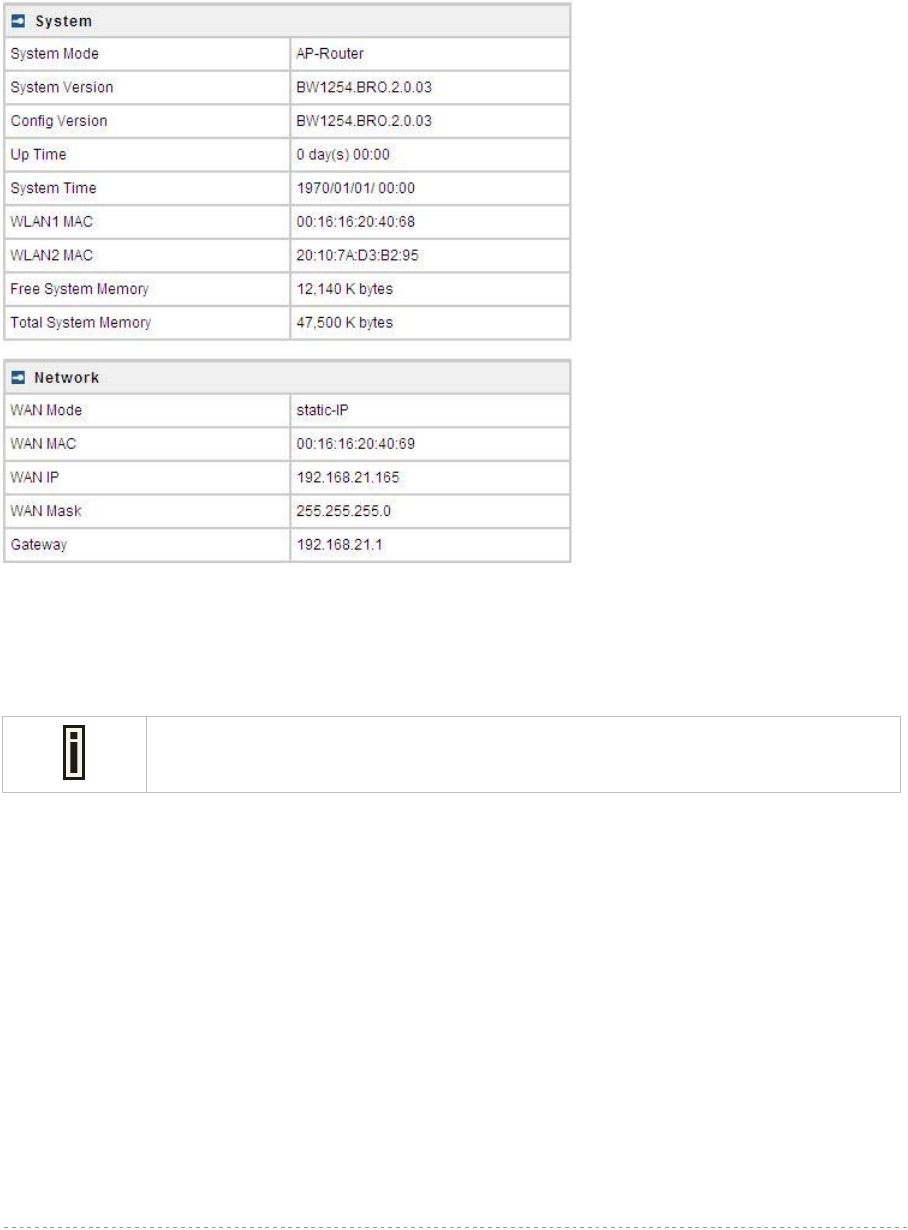
BW1254 User Guide v1.0 Nov. 2013
Page 81 of 184
Status
Status | Device Status
The Device Status page shows important information of system status and network configuration for
the BW1254.
Figure 134 – Device Status
System Mode – display the BW1254 works in AP mode or AP-Router mode
System Version – display the current version of the firmware loaded to the AP
This is important information for support requests and for preparing firmware
upgrading
Config version – display current configure version
Up Time – indicate the time, expressed in days, hours and minutes since the system was last
rebooted
System Time – show the current time of the BW1254
WLAN1 MAC – show the MAC addresses of the wireless interfaces of the BW1254[2G]
WLAN2 MAC – show the MAC addresses of the wireless interfaces of the BW1254[5G]
Free System Memory – indicate the memory currently available in the BW1254
Total System Memory – indicate the total memory in the BW1254
WAN Mode – indicate static IP or DHCP client is used for BW1254 WAN IP address
WAN IP – show the WAN IP address of BW1254
WAN Mask – show the WAN Network Mask of BW1254
Gateway – show the default gateway of BW1254
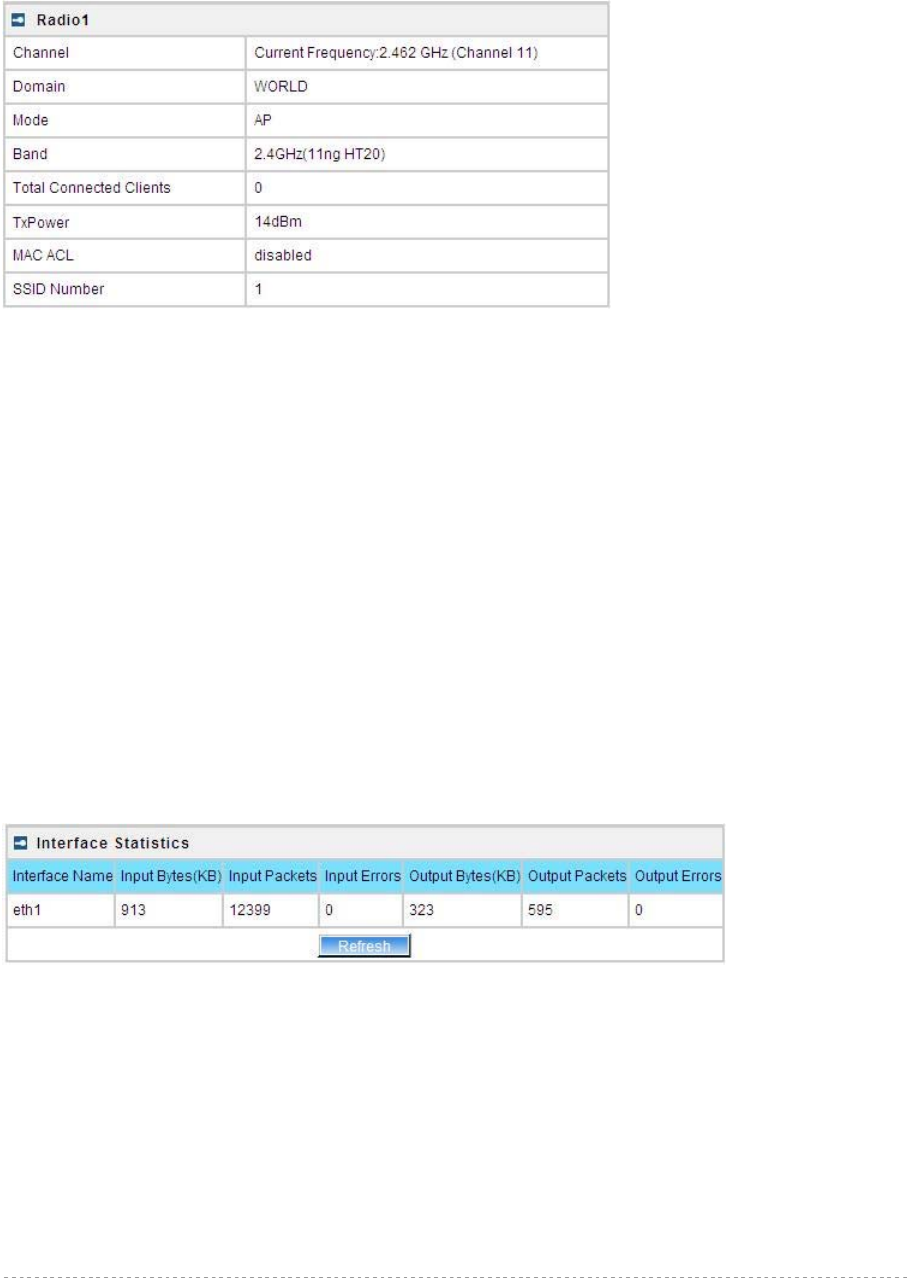
BW1254 User Guide v1.0 Nov. 2013
Page 82 of 184
Status | Wireless Status
The wireless status shows the information related with BW1254 wireless interfaces.
Figure 135 – Wireless Status
Radio1 – show the wireless interface.
Channel – indicate which channel is in use.
Domain – indicate regulatory domain set on the BW1254
Mode – AP or Bridge mode is be used for this wireless interface
Band – specify which band is in use for wireless interface
Total Connected Clients – indicate number of the currently connected clients to your BW1254
Tx Power – indicate radio transmit power of the BW1254
MAC ACL – indicate the status of MAC ACL feature on BW1254
SSID Number – indicate current number of enabled SSID on BW1254
Status | Interface Statistics
The Interface Statistics shows each network interface status, including Input / Output bytes, packets
or error.
Figure 136 – Interface Statistics
Interface Name – show the name of each network interface, where ixp0 is related to LAN interface,
wlan1_x is related to wireless sub-interface.
Input Bytes (KB) – show the total number of bytes received on the network interface. The bytes
number is displayed in KB.
Input Packets – show the packets number received on the network interface.
Input Errors – show the packets number which contain errors preventing them from being received
correctly.
Output Bytes (KB) – show the total number of bytes transmitted out of the network interface. The
bytes number is displayed in KB.

BW1254 User Guide v1.0 Nov. 2013
Page 83 of 184
Output Packets – show the packets number transmitted out of the network interface.
Output Errors – show the packets number which contain errors preventing them from being
transmitted out correctly.
Refresh – get the updated network interface information.
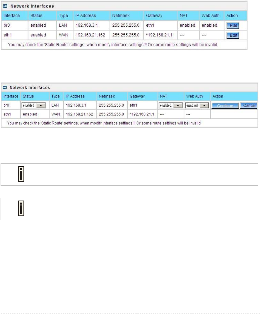
BW1254 User Guide v1.0 Nov. 2013
Page 84 of 184
Network
Network | Interface
The AP-Router contains two kinds of network interfaces: eth1 is worked as wide area network (WAN)
interface for Access Points; each BSS interface is worked as local area network (LAN) interface which
bridge into the br0 interface. The WAN port connects to the Internet or the service provider’s
backbone network. Each BSS can be looked as a virtual AP, wlan1_0 is the virtual AP for wireless
network.
All these interfaces are listed in the Network Interfaces page. All network interfaces available in the
AP-Router are shown in the following table:
Figure 137 – Network Interface Table
To change network interface configuration properties click the Edit button in the Action column. The
status can be changed now:
Figure 138 – Edit Network Interfaces Settings - 1
Interface – standard interface name. This name cannot be edited
Status – select the status of interface [enabled/disabled]
Do not disable the interface through which you are connected to the AP Router.
Disabling such interface will lose your connection to the device.
The interface eth1 can not be disabled.
Type – network type cannot be changed. There are two possible networking types:
LAN – interface is used as local area network (LAN) gateway, and is connected to a LAN
WAN – interface is used to access the ISP network
NAT – select enable/disable the NAT service of current interface. If enabled, users can access the
Internet under its network gateway address [enabled/disabled]
Web Auth – select enable/disable the Web Login Authentication of current interface. With disabled
authentication, the user from his LAN gets access to the Internet without any authentication. If
enabled, authentication for Internet access is required for all users [enabled/disabled]
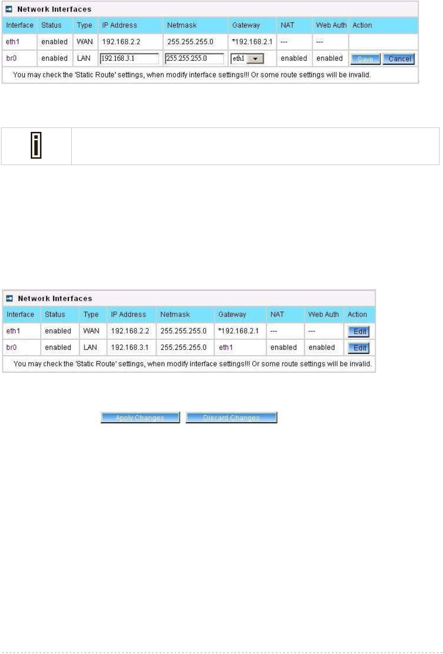
BW1254 User Guide v1.0 Nov. 2013
Page 85 of 184
Change status or leave in the default state if no editing is necessary and click the Continue button.
Then the following parameters can be changed:
Figure 139 –Edit Interface Configuration Settings - 2
IP Address – specify new interface IP address [dots and digits]
Under ap-router mode,IP address of each interface should be configured different
subnet; otherwise, you will receive an error message.
Netmask – specify the subnet mask [[0-255].[0-255].[0-255].[0-255]]. These numbers are a binary
mask of the IP address, which defines IP address order and the number of IP addresses in the subnet
Gateway – interface gateway. For LAN type interfaces, the gateway is WAN interface. The gateway
of the WAN interface is usually the gateway router of the ISP or other WAN network [Default gateway
is marked with ‘*’]
Save – save the entered values.
Cancel – restore all previous values.
Figure 140 – Apply or Discard Interface Configuration Changes
Apply Changes – save all changes in the interface table at once.
Discard Changes – restore all previous values.
For such change of settings, the BW1254 needs to be restarted to apply all settings changes when
clicking Apply Changes. Request for reboot server appears:
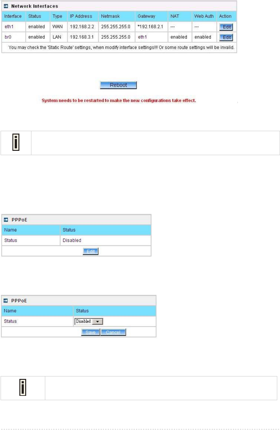
BW1254 User Guide v1.0 Nov. 2013
Page 86 of 184
Figure 141 – Reboot Server
Reboot – click the button to restart the server and apply the changes.
If there is no other settings needed to be modified, click the Reboot button to apply all
changes. If there are any other settings need to be changed, continuously to finish and
apply all changes and then click Reboot button to restart and take effect for all settings.
Network | PPPoE
The Point-to-Point Protocol over Ethernet(PPPoE) is a network protocol for encapsulating PPP frames
inside Ethernet frames. It is use mainly for DSL service.
Click Edit button to enable or disable the service.
Figure 142 – PPPoE service
Name – service name
Status – change status for this service.[disable/enable]
Figure 143 – change PPPoE service
Enable the PPPoE service.
Username – enter the authorized user to connect to the server [text string, can not be empty].
The same username should be configured on the PPPoE server.
Password – the password of the user. [text string, can not be empty]
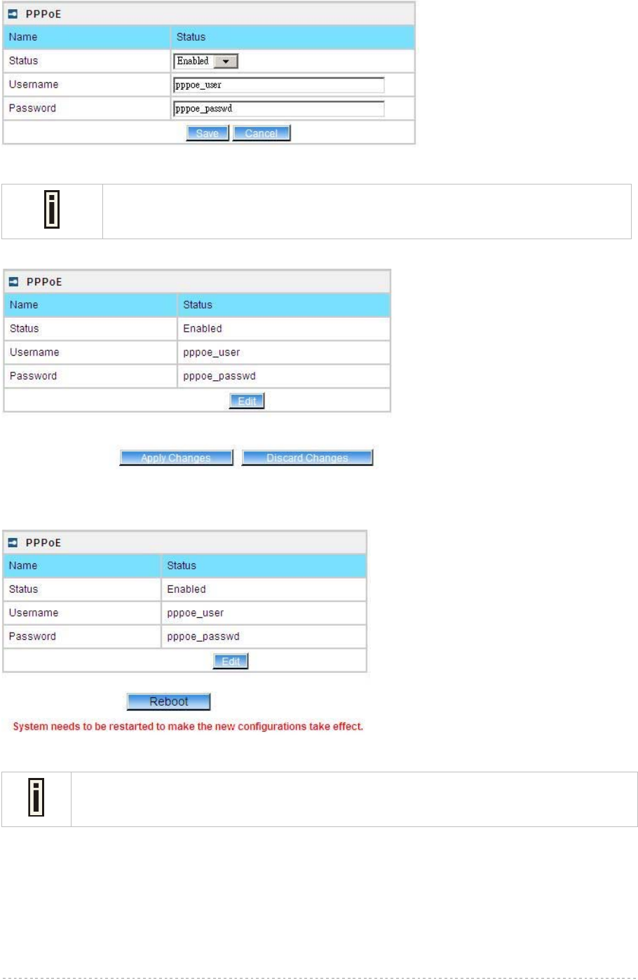
BW1254 User Guide v1.0 Nov. 2013
Page 87 of 184
Figure 144 – edit PPPoE service
Default WAN gateway specified in Network | Interface page will not be used,
because all Internet traffic will be sent/received via the specified PPPoE server
(tunnel).
Click Save and Apply Changes button to take effect the changes.
Figure 145 – apply changes
Reboot – click the button to restart the AP and apply all the changes.
Figure 146 – reboot and take effect all changes
If there is no other settings needed to be modified, click the Reboot button to apply all
changes. If there are any other settings need to be changed, continuously to finish and
apply all changes and then click Reboot button to restart and take effect for all settings.
Network | L2TP
Layer 2 Tunneling Protocol(L2TP) is a tunneling protocol used to support virtual private networks
(VPNs) or as part of the delivery of services by ISPs. It does not provide any encryption or
confidentiality by itself. Rather, it relies on an encryption protocol that it passes within the tunnel to
provide privacy.
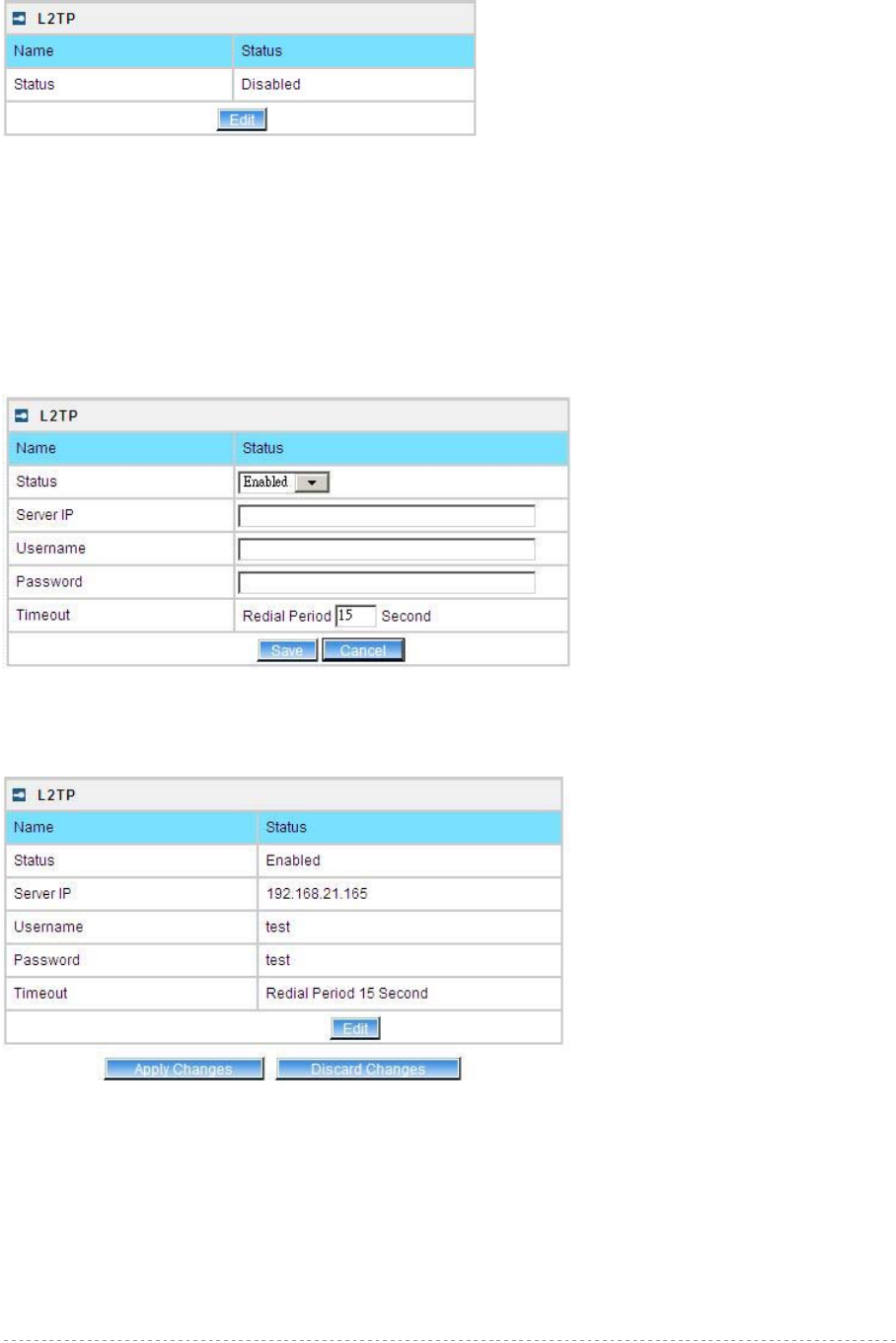
BW1254 User Guide v1.0 Nov. 2013
Page 88 of 184
Click Edit button to enable or disable the service.
Figure 147 – L2TP services
Name – service name
Status – change status for this service.[disable/enable]
Server IP – enter the server IP address. [in digits and dots notation, e.g. 192.168.2.2]
Username – enter the user name.
Password – password for the authorized user.
Timeout – in case of connection fail, the interval to re-connect to the server.
Figure 148 – edit L2TP services
Click Save button and Apply Changes button to save the change or discard changes button to
discard the change
Figure 149 – save the changes
Reboot – click the button to restart the AP and apply all the changes.
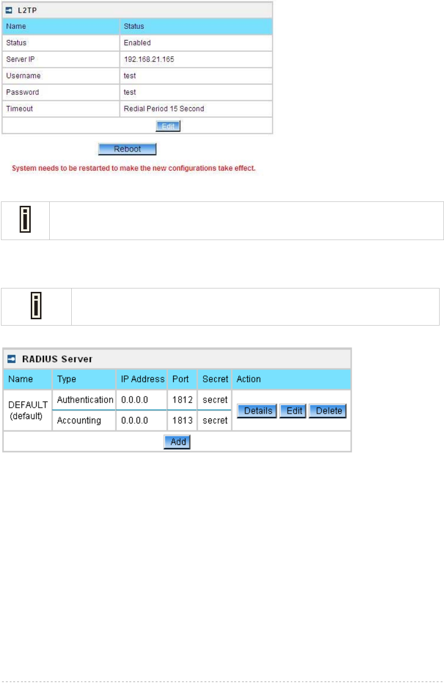
BW1254 User Guide v1.0 Nov. 2013
Page 89 of 184
Figure 150 – reboot and take effect the changes
If there is no other settings needed to be modified, click the Reboot button to apply all
changes. If there are any other settings need to be changed, continuously to finish and
apply all changes and then click Reboot button to restart and take effect for all settings.
Network | RADIUS Server
Up to 32 different RADIUS servers can be configured in the RADIUS servers
menu.
By default, one RADIUS server is specified for the system:
Figure 151 – RADIUS Servers Settings
Details – show the detail information of this RADIUS Server profile
Edit – edit the selected RADIUS Server entry you want to configure
Delete – delete the selected RADIUS Server entry. The last entry can not be deleted
Add – add new RADIUS server.
Click Details, a similar page will be appeared as below:
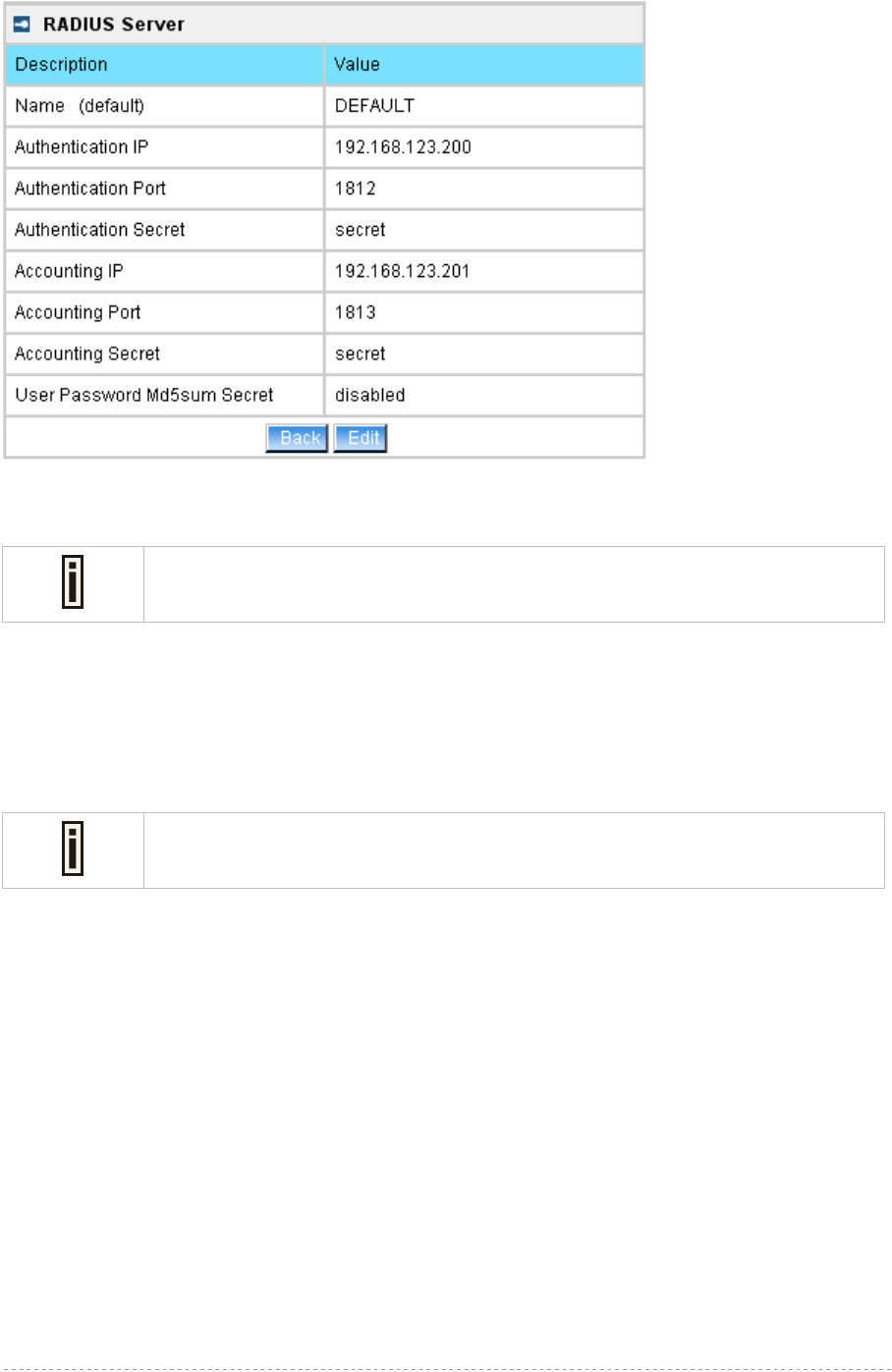
BW1254 User Guide v1.0 Nov. 2013
Page 90 of 184
Figure 152 – Detail for Radius Server profile
Name – the new RADIUS server name which is used for selecting RADIUS server
If a “(default)” appears on the right side of the Name entry, it means this RADIUS
server profile is the default profile.
Authentication IP – show the IP address of Authentication RADIUS server
Authentication Port – show the network port used to communicate with the Authentication RADIUS
server
Authentication Secret – show the shared secret string that is used to make sure the integrity of data
frames used for the Authentication RADIUS server
Accounting IP – show the IP address of Accounting RADIUS server
If the Accounting IP address is 0.0.0.0, it means that the Accounting service is
disabled.
Accounting Port – show the network port used to communicate with the Accounting RADIUS server
Accounting Secret – show the shared secret string that is used to make sure the integrity of data
frames used for the Accounting RADIUS server
User Password Md5sum Secret – show whether user input password is calculated md5-sum before
pass to RADIUS server or not.
Back – back to the RADIUS Server main page
Edit – edit the selected RADIUS Server profile
Click Edit or click Add / Edit button in the main page to configure RADIUS server settings.
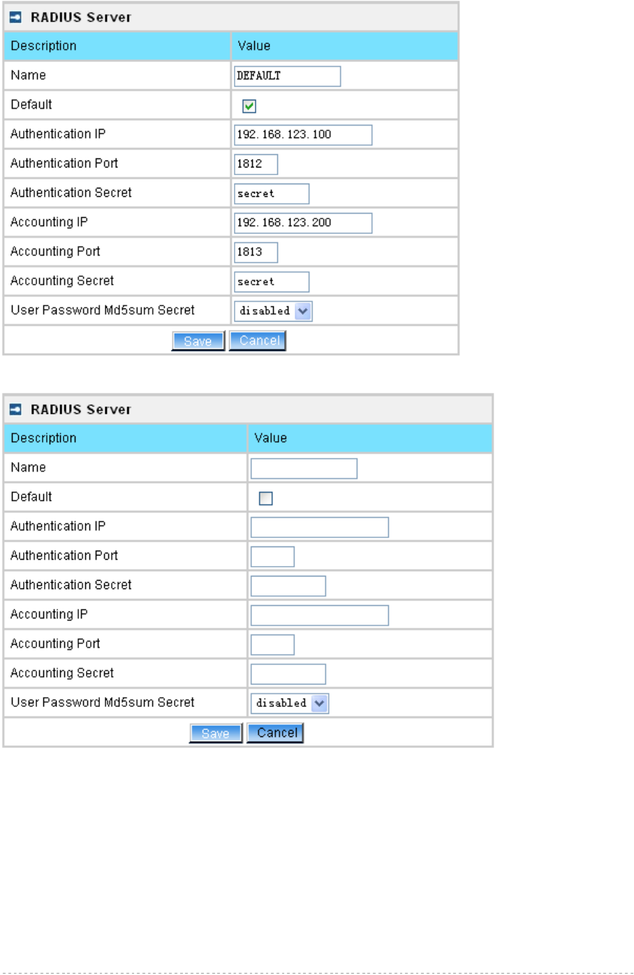
BW1254 User Guide v1.0 Nov. 2013
Page 91 of 184
Figure 153 – Edit the RADIUS Server’s profile
Figure 154 – Add a new RADIUS Server's profile
Name – specify the new RADIUS server name which is used for selecting RADIUS server
Default – specify this RADIUS profile as default or not. When selected, the profile will be used as
default
Authentication IP – specify the IP address of Authentication RADIUS server [dots and digits]
Authentication Port –specify the network port used to communicate with the Authentication RADIUS
server [1-65535]
Authentication Secret – shared secret string that is used to make sure the integrity of data frames
used for the Authentication RADIUS server
Accounting IP – specify the IP address of Accounting RADIUS server [dots and digits]
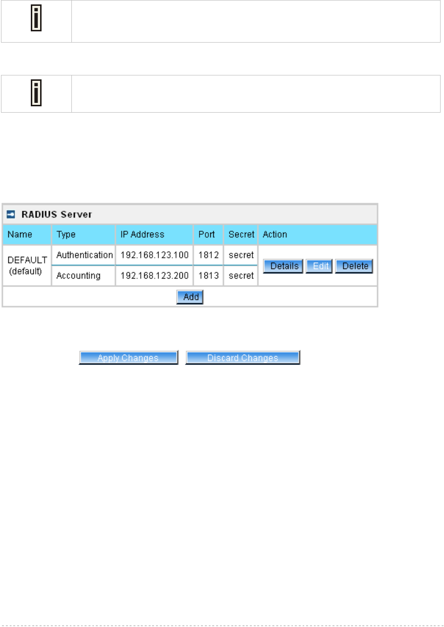
BW1254 User Guide v1.0 Nov. 2013
Page 92 of 184
Accounting Port –specify the network port used to communicate with the Accounting RADIUS server
[1-65535]
Accounting Secret – shared secret string that is used to make sure the integrity of data frames used
for the Accounting RADIUS server
The default port value for authentication is 1812.
The default port value for accounting is 1813.
The port specified here must be the same with the one on the RADIUS server.
User Password Md5sum Secret – if enabled, user input password will be calculated md5-sum
before pass to RADIUS server for more security [enabled/disabled]
This setting needs RADIUS server do relevant configurations.
Save –save the entered values
Cancel – restore all previous values
After adding a new RADIUS server or editing an existing one, a page appears similar to the following:
Figure 155 – Apply or Discard RADIUS Server Changes
Details – show the detail information of this RADIUS Server profile
Edit – edit the selected RADIUS Server entry you want to configure
Delete – delete the selected RADIUS Server entry. The last entry can not be deleted
Add – add new RADIUS server.
Apply Changes – to save all changes at once.
Discard Changes – restore all previous values.
Click Apply Changes to apply all the changes. Then the follow similar page will appear:
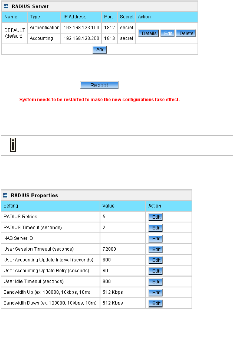
BW1254 User Guide v1.0 Nov. 2013
Page 93 of 184
Figure 156 – Reboot Server
Reboot – restart the access point to make applied changes work.
If there is no other settings needed to be modified, click the Reboot button to apply all
changes. If there are any other settings need to be changed, continuously to finish and
apply all changes and then click Reboot button to restart and take effect for all settings.
Network | RADIUS Properties
General RADIUS settings are configured using the RADIUS Properties menu under the network:
Figure 157 – RADIUS Properties settings
RADIUS Retries – retry count of sending RADIUS packets before giving up [0-99]
RADIUS Timeout (seconds) – maximum amount of time before retrying RADIUS packets [1-999]
NAS Server ID – name of the RADIUS client
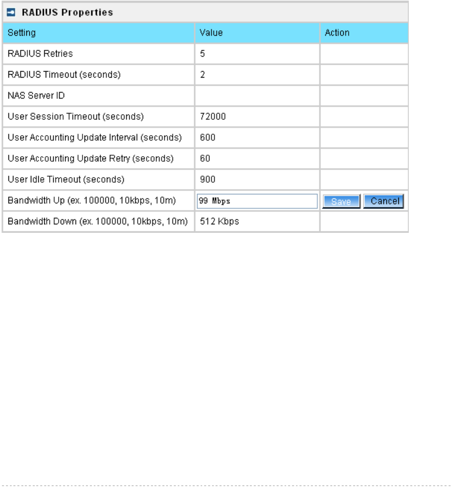
BW1254 User Guide v1.0 Nov. 2013
Page 94 of 184
User Session Timeout (seconds) – amount of time from the user side (no network carrier) before
closing the connect [1-999999999]
User Accounting Update Interval (Seconds) – period after which server should update accounting
information [60-999999999]
User Accounting Update Retry (seconds) – retry time period in which server should try to update
accounting information before giving up [60-999999999]
User Idle Timeout (seconds) – amount of user inactivity time, before automatically disconnecting
user from the network [1-999999999]
Bandwidth Up – maximum bandwidth up at which corresponding user is allowed to transmit [bps]
Bandwidth Down – maximum bandwidth down at which corresponding user is allowed to receive
[bps]
Each setting in this table can be edited. Select RADIUS setting you need to update, click the edit next
to the selected setting and change the value:
Figure 158 – edit RADIUS properties
Use the save button to save an entered value. Now select another RADIUS property to edit, or Apply
Changes and restart your AP if the configuration is finished:
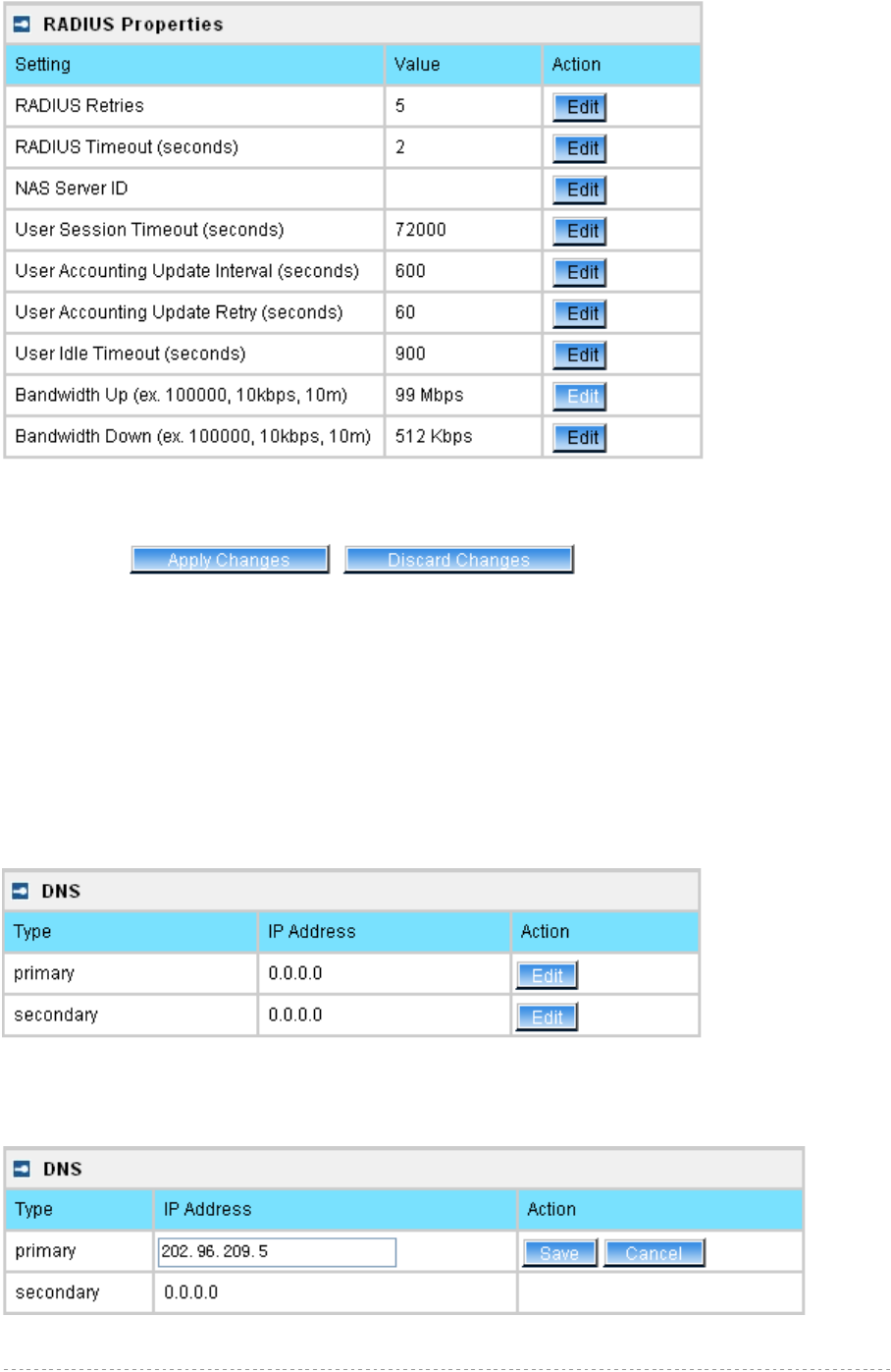
BW1254 User Guide v1.0 Nov. 2013
Page 95 of 184
Figure 159 – apply change RADIUS properties
Apply Changes – click if RADIUS Properties configuration is finished
Discard Changes – restore all previous values
Network | DNS
DNS (Domain Name Service) service allows BW1254 subscribers to enter URLs instead of IP
addresses into their browser to reach the desired web site. You can enter the DNS server settings
under the Network | DNS menu. The DNS server setting s table is displayed:
Figure 160 – DNS Settings
You can enter the primary and secondary DNS servers’ settings by click the edit button in the
action column and type in the DNS server’s IP address:
Figure 161 – Edit DNS Settings
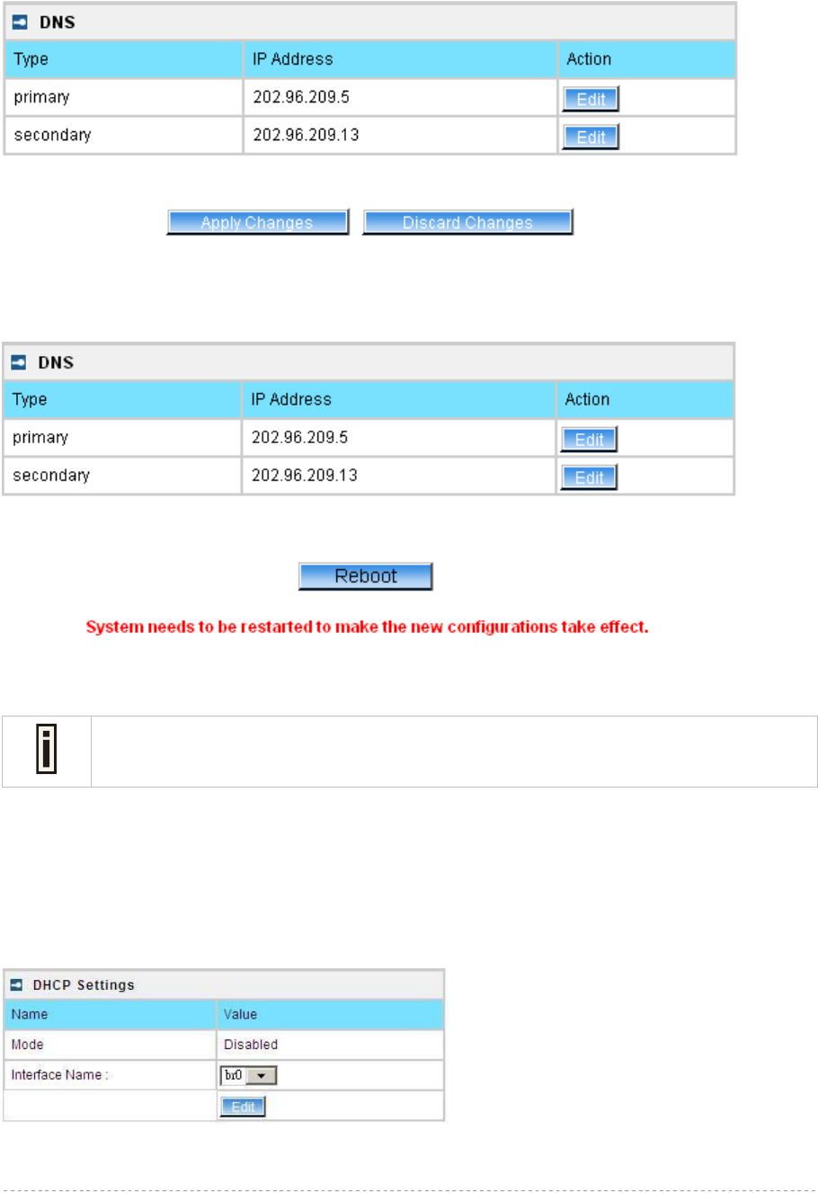
BW1254 User Guide v1.0 Nov. 2013
Page 96 of 184
IP Address – enter the primary or secondary DNS server’s IP address [dots and digits]
Change status or leave in the default state if no editing is necessary and click the Save button.
Figure 162 – Apply or Discard DNS server Settings
For each change of settings, the BW1254 needs to be restarted to apply all settings changes when
clicking Apply Changes. Request for reboot server appears:
Figure 163 – Reboot information
Reboot – click the button to restart the server and apply the changes.
If there is no other settings needed to be modified, click the Reboot button to apply all
changes. If there are any other settings need to be changed, continuously to finish and
apply all changes and then click Reboot button to restart and take effect for all settings.
Network | DHCP
In AP Router mode, the BW1254 can act as a DHCP Server. The DHCP (Dynamic Host
Configuration Protocol) service is supported on the LAN interfaces. This service enables clients on the
LAN to request configuration information, such as an IP address, from a server. This service can be
viewed in the following table:
Figure 164 – DHCP Configuration
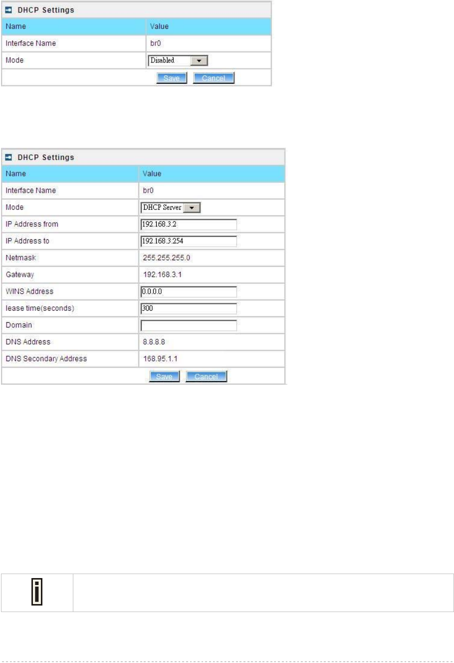
BW1254 User Guide v1.0 Nov. 2013
Page 97 of 184
Interface Name – select which LAN interface to be configured.[only br0 interface in BW1254]
Select the interface, and then click Edit button, a similar screen will appear as below:
Figure 165 – Set DHCP Mode
Mode – DHCP service mode [DHCP server/Disabled]
When DHCP Server is selected, a page appears similar to the following:
Figure 166 – DHCP Server Settings
IP Address from/IP Address to – specify the IP address range supported for the DHCP service
[mandatory fields]
Netmask – show the subnet mask of current interface
Gateway – show the interface gateway
WINS (Windows Internet Naming Service) Address – specify service IP address if it is available on
the network [dots and digits]
Lease Time – specify the IP address renewal in seconds [1-1000000]
Domain – specify DHCP domain name [optional, 1-128 sting]
DNS Address – specify the DNS server’s IP address [digits and dots]
DNS Secondary Address – specify the secondary DNS server’s IP address [digits and dots]
The DNS address is same with the setting in the Network | DNS menu.
Change status or leave in the default state if no editing is necessary and click the Save button.
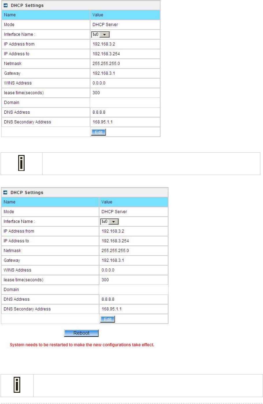
BW1254 User Guide v1.0 Nov. 2013
Page 98 of 184
Figure 167 – Apply or Discard DHCP server Settings
The DHCP server settings will be automatically adjusted to match the network
interface settings.
If all of the DHCP settings are correct, click Apply Changes, request for reboot server appears:
Figure 168 – Reboot information
Reboot – click the button to restart the server and apply the changes.
If there is no other settings needed to be modified, click the Reboot button to apply all
changes. If there are any other settings need to be changed, continuously to finish and
apply all changes and then click Reboot button to restart and take effect for all settings.
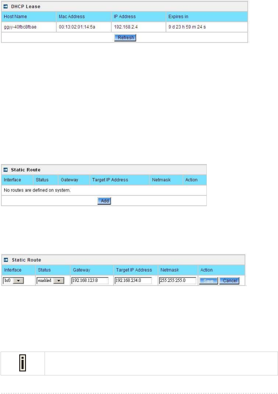
BW1254 User Guide v1.0 Nov. 2013
Page 99 of 184
Network | DHCP Lease
This page display the DHCP lease information of wireless client which connect to the AP when DHCP
server enable.
Figure 169 – DHCP lease information
Host Name – the host name of wireless client which associate to the access point.
Mac Address –the MAC address of wireless client which associate to the access point.
IP Address –the IP address of wireless client which associate to the access point.
Expires in – expire time of the wireless client which associate to the access point.
Network | Static Route
Opening the Static Route Settings page you will find a list of all pre-configured routes, each
consisting of the related interface, the destination IP address, the gateway and the subnet mask.
The Routing Table content shows how the router will handle data packets received on an interface
with specific destination addresses. By default no static routes are defined on the system:
Figure 170 – Static Route Page
A routing rule is defined by the target subnet (target IP address and subnet mask), interface and/or
gateway where to route the target traffic. A data packet that is directed to the target network is routed
to the specified AC interface or to another gateway router. To add a new static route for the system,
click the new button under the action column and specify the following parameters:
Figure 171 – Add New Route
Interface – choose device interface for the route
Status – set new static route status: [enabled/disabled]
Gateway – enter the gateway address for the route. 0.0.0.0 stands for the default gateway of the
selected interface [IP address]. The gateway is in the same subnet with selected interface.
Target IP address – enter host IP or network address to be routed to [IP address]
In this case the class C network(192.168.234.x) is reachable.
Netmask – enter the target network netmask [dots and digits]
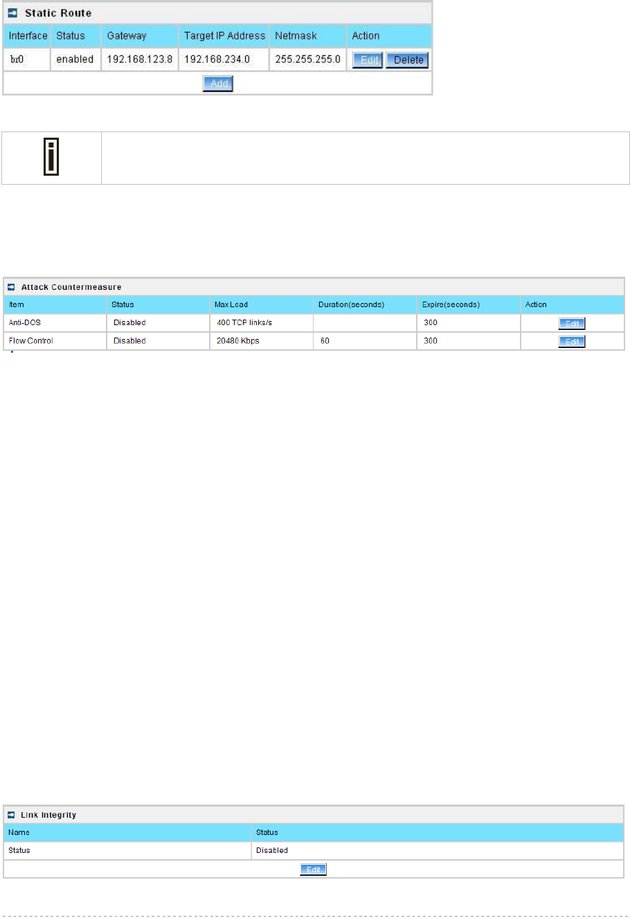
BW1254 User Guide v1.0 Nov. 2013
Page 100 of 184
Save – save the new route
Cancel – restore all previous values
Figure 172 – Save New Route
Static route will take effect immediately after click save button.
Network | Attack Countermeasure
To protect BW1254 from outside attack, anti-attack polices can be set here based on network needs.
Figure 173– Attack Countermeasure settings
Anti-DOS
Status – Enable or disable anti-dos policy for BW1254. This policy is for TCP DOS attack.
Max Load – The attack threshold. BW1254 think there is TCP DOS attack and do the
countermeasure if one client’s TCP links exceed this threshold.
Expire(seconds) – If one client is considered as DOS attacker, BW1254 kicks it out and doesn’t
let it connect again during the time that Expire set.
Flow Control
Status – Enable or disable traffic flow control policy for BW1254.
Max Load – The attack throughput threshold.
Duration(seconds) – if traffic exceeds the value of Max Load during the whole time that
Duration set, BW1254 think there is traffic flow attack and do the
countermeasure.
Expire(seconds) – If one client is considered as traffic flow attacker, BW1254 kicks it out and
doesn’t let it connect again during the time that Expire set.
Network | Link Integrity
Specify Link Integrity feature’s settings here. Enable Link Integrity, BW1254 will close wireless
connections and kick out all the wireless clients when it detects that its Ethernet network cannot
access to the internet.
Figure 174 – Link Integrity settings
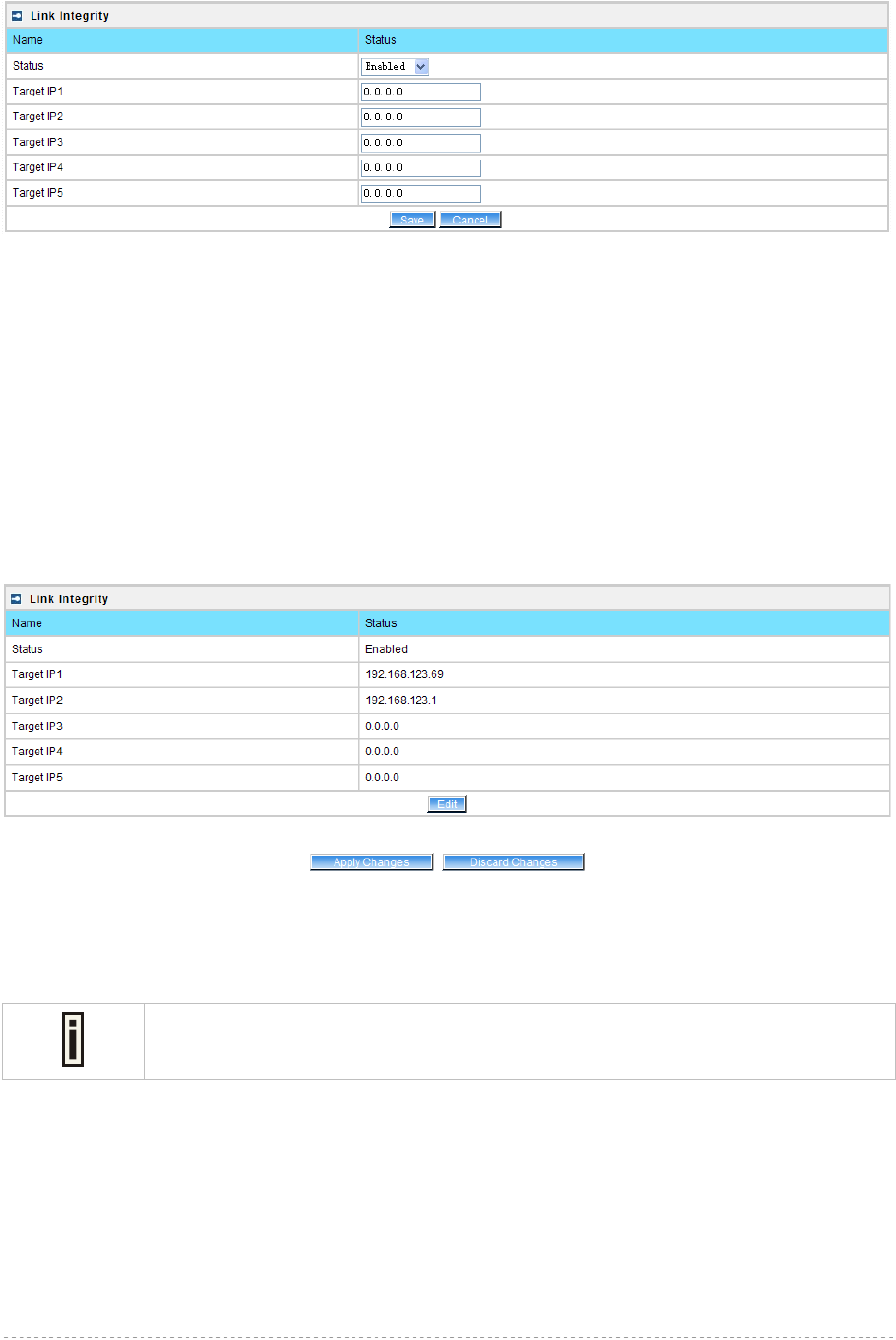
BW1254 User Guide v1.0 Nov. 2013
Page 101 of 184
Click Edit button to set the Link Integrity settings, the similar UI will be appeared as below:
Figure 175 – Edit Link Integrity settings
Status – Enable or disable the feature of Link Integrity
Target IP1 to Target IP5 – IP addresses for BW1254 detecting if its Ethernet interface can access
network. The AP will ping every IP address 15 times in sequence. As long as one ping is success it
will consider the network is reachable. If ping fail for all IP address specified it will consider Ethernet
link fail and all associated wireless client will be logged out. The AP will continue to ping from first IP
address. If ping success the wireless will be enable again and client can access the AP.
Save – save the entered values.
Cancel – restore all previous values.
Click Save, the similar apply changes UI will be appeared:
Figure 176 –Apply or Discard Link Integrity Settings
Apply Changes – save all changes in the interface table at once.
Discard Changes – restore all previous values.
Maximum 5 target IP can be siecified.
The BW1254 needs to be restarted to apply all settings changes when clicking Apply Changes.
Request for reboot server appears:
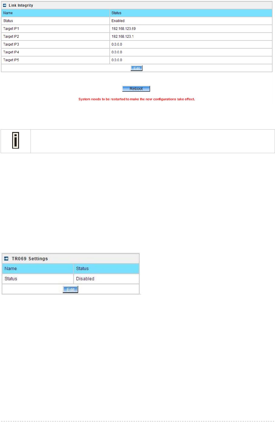
BW1254 User Guide v1.0 Nov. 2013
Page 102 of 184
Figure 177 – Reboot Server
Reboot – click the button to restart the server and apply the changes.
If there is no other settings needed to be modified, click the Reboot button to apply all
changes. If there are any other settings need to be changed, continuously to finish and
apply all changes and then click Reboot button to restart and take effect for all settings.
Network | Tr069 Settings
TR-069 is the Broadband Forum technical specification entitled CPE WAN Management
Protocol(CWMP). It defines an application layer protocol for remote management of end-user devices.
As a bidirectional SOAP/HTTP-based protocol, it provides the communication between customer-
premises equipment(CPE) and Auto Configuration Servers(ACS server). It includes both a safe auto
configuration and the control of other CPE management functions within an integrated framework.
The protocol addressed the growing number of different internet access devices such as
modems,routers,gateways,set-top-boxes,and VOIP-phones for the end users. The TR-069 standard
was developed for automatic configuration of these devices with Auto Configuration Servers(ACS).
configure the remote management through TR069 ACS server(eg:BROWAN DMS server)
Figure 178 – TR-069 settings
Click Edit button and the similar page will be appeared.

BW1254 User Guide v1.0 Nov. 2013
Page 103 of 184
Figure 179 – edit TR-069 settings
Status – enable or disable TR-069 setting.[enable/disable]
ACS URL – enter the ACS server URL.
ACS UserName – the user name for AP register to ACS server.
ACS UserPassword – the password for AP register to ACS server.
Enable Periodic Inform – when AP registered to the ACS server, it will automatically send inform
message such as S/N,OUI,manufacturer and product name to the ACS server through TR-069
protocol in a periodic time.
Periodic Inform Interval – the inform interval.[in seconds, the value is 720~4294967295]
Connection Request UserName – when the ACS pulling a task to AP/CPE such as firmware
upgrade/downgrade, AP need the user name to verify the task sending from ACS server.
Connection Request Password –when the ACS pulling a task to AP/CPE such as firmware
upgrade/downgrade, AP need the password to verify the task sending from ACS server.
Contact the ACS server administrator to get the user name and password for
Connection Request UserName and Connection Request Password otherwise the
AP will not accept the task pulling by ACS server.
After enter all field click save and apply changes button to take effect.
Figure 180 – save TR-069 settings
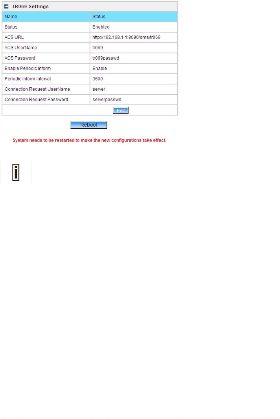
BW1254 User Guide v1.0 Nov. 2013
Page 104 of 184
Reboot – click the button to restart the server and apply the changes.
Figure 181 – reboot device
If there is no other settings needed to be modified, click the Reboot button to apply all
changes. If there are any other settings need to be changed, continuously to finish and
apply all changes and then click Reboot button to restart and take effect for all settings.
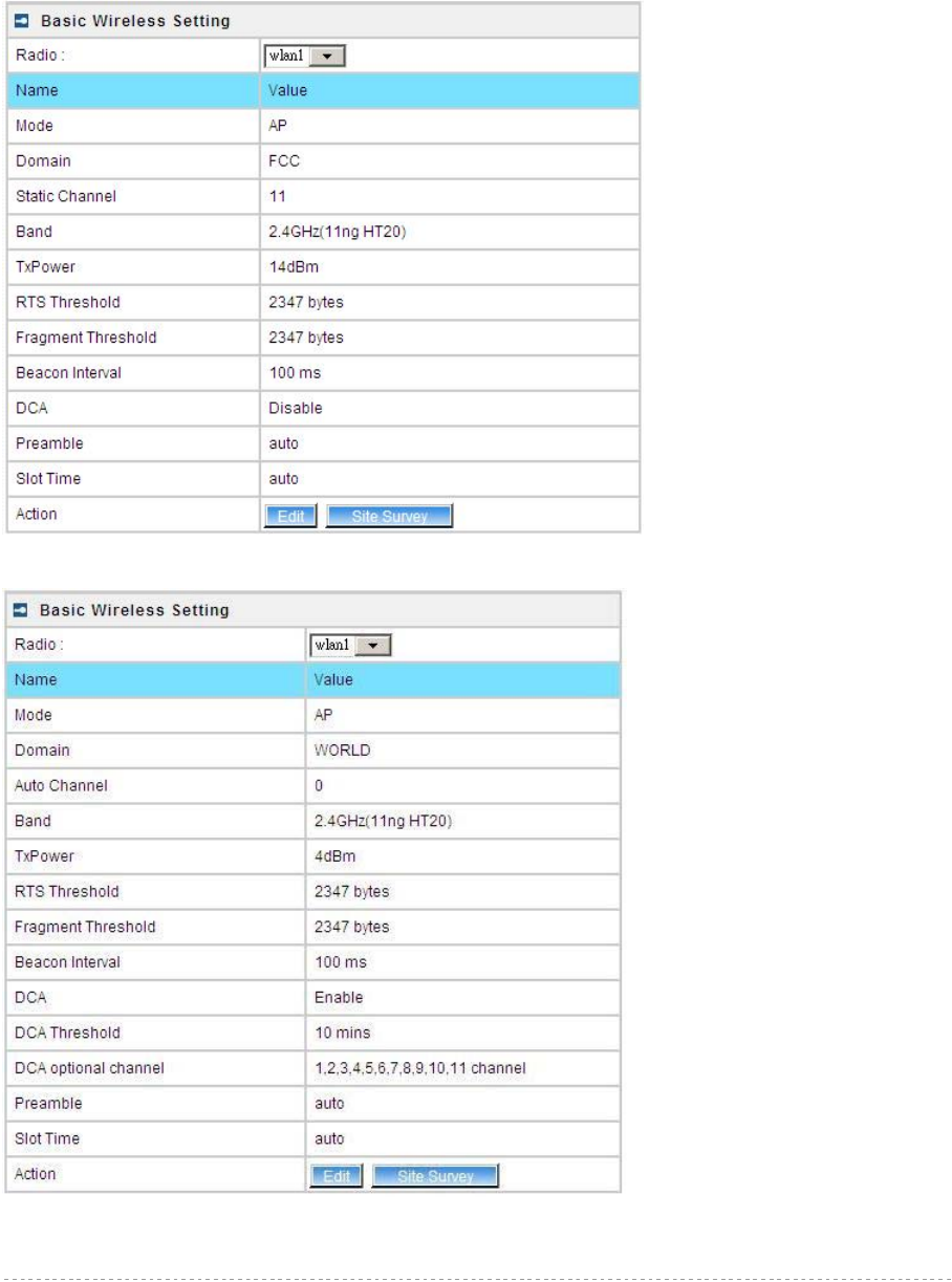
BW1254 User Guide v1.0 Nov. 2013
Page 105 of 184
Wireless
Wireless | Basic
Use the Wireless | Basic menu to configure wireless settings such as regulatory domain, channel,
band, and power, layer 2 isolation. Click the edit button on the setting you need to change:
Figure 182 – Basic Wireless Settings with static channel selection
Figure 183 – Basic Wireless Settings with auto channel selection(DCA)

BW1254 User Guide v1.0 Nov. 2013
Page 106 of 184
Radio – specify which wireless interface of BW1254 is shown. [wlan1(2.4G)/wlan2(5G)]
Mode – show the radio operation mode. (AP mode or Bridge mode)
Domain – show the regulatory domain
Static Channel / Auto Channel – show the channel that the access point will use to transmit and
receive information
If DCA (Dynamic Channel Allocation) is enabled, this will show Auto Channel and
its channel number is chosen in auto channel selection.
If use static channel selection, this will show Static Channel and its channel
number.
DCA (Dynamic Channel Allocation) is useful feature to help choose the best
channel automatically and reduce interference among many Access Points.
Band – show the working bands on which the radio is working.
wlan1:four bands listed: 2.4GHz(11g only) , 2.4GHz(11n HT20) , 2.4GHz(11n HT20/40plus),
2.4GHz(11n HT20/40minus)
wlan2: four bands listed:5GHz(11a), 5GHz(11n HT20) , 5GHz(11n HT20/40plus), 5GHz(11n
HT20/40minus) .
By default, the HT20/40 is recommended.
Tx Power – show the BW1254 transmission output power (without antenna gain) in dBm.
RTS Threshold –the AP sends Request to Send(RTS) frames to a particular receiving station and
negotiates the sending of a data frame. After receiving an RTS, the wireless station responds with a
Clear to Send(CTS) frame to acknowledge the right to begin transmission. The default value is
2347.[recommend].
Fragment Threshold –It specifies the maximum size for a packet before data is fragmented into
multiple packets. If you experience a high packet error rate, you may slightly increase the
fragmentation threshold. Setting the fragmentation threshold too low may result in poor network
performance. Only minor modifications of this value are recommended. The default value is
2347.[recommend]
Beacon Interval –the Beacon Interval value indicates the frequency interval of the beacon. A beacon
is a packet broadcast by the AP to synchronize the wireless network.
DCA – Enable or Disable DCA service. DCA can help to choose the best working channel
automatically. And static channel selection will be forbidden if DCA is enabled.
DCA(Dynamic Channel Allocation) solution automatically select the optimal operational frequency
channel when power up and periodically monitors the environment and adjusts for the best
operational frequency channel.
DCA threshold – specify the value (in minutes) of DCA threshold. This threshold is been used to
judge if there is no wireless users connected during this time. And if yes, BW1254 will monitor the
environment and adjust channel for the best operational one.
If wireless network environment is stable which means auto channel selection
needn’t do frequently, set a big value for DCA threshold to gain a stable wireless
users’ connection.
If wireless network environment changes continually, frequent auto channel
selection is needed. So set a relative small value for DCA threshold to let channel
change based on wireless environment.

BW1254 User Guide v1.0 Nov. 2013
Page 107 of 184
Wireless users’ will be kicked off when DCA is processing (new operational
frequency channel takes effect).
DCA optional channel – show the channels only in which auto channel selection (DCA) will be
processed to reduce interference.
Only when DCA is enabled, DCA threshold and DCA optional channel will be
shown.
Preamble – if your wireless device supports the short preamble and you are having trouble getting it
to communicate with other 802.11b devices, make sure that it is set to use the long preamble.
Auto: using long preamble when there are clients not supporting short preamble connected ,
otherwise using short preamble. The default is Auto.[recommend]
Short: always using short preamble.
Long: always using long preamble.
Slot Time – show the slot time policy when working in 2.4GHz band.
Auto: using long slot time when there are clients not supporting short slot time connected in,
otherwise using short slot time. The Switching between long and short slot time is automatic.
Short: always using short slot time.
Long: always using long slot time.
To Maximize the compatibility with some 11b clients, set both Preamble and Slot
Time to long.
Edit – edit the wireless basic settings
To change basic wireless setting properties click the Edit button in the Action column. The status
can be changed now:
Figure 184 – Edit Basic Wireless Settings with static channel selection
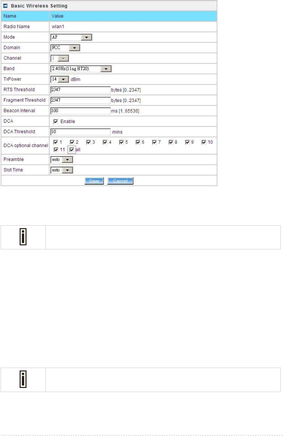
BW1254 User Guide v1.0 Nov. 2013
Page 108 of 184
Figure 185 – Edit Basic Wireless Settings with DCA enabled
Radio Name – specify wireless interface of BW1254 is shown
Mode – configure the radio operation mode.
In AP-Router mode, the radio only support AP mode for wireless client connection.
Domain – select the regulatory domain.
Channel – select the channel that the access point will use to transmit and receive information. If one
channel is defined, it acts as default channel. Channels list will vary depending on selected regulatory
domain and selected band. If you wish to operate more than one access point in overlapping
coverage areas, we recommend at least four channels interval between the chosen channels. For
example, for three Access Points in close proximity choose channels 1, 6 and 11 for 11b/g or
channels 36, 40 and 64 for 11a.
Band – show the working bands on which the radio is working.
wlan1:four bands listed: 2.4GHz(11g only) , 2.4GHz(11n HT20) , 2.4GHz(11n HT20/40plus),
2.4GHz(11n HT20/40minus)
wlan2: four bands listed:5GHz(11a), 5GHz(11n HT20) , 5GHz(11n HT20/40plus), 5GHz(11n
HT20/40minus) .
TxPower – the BW1254 transmission output power in dBm.
The value of the TxPower varies according to channel and regulatory domain.
RTS Threshold – the AP sends Request to Send(RTS) frames to a particular receiving station and
negotiates the sending of a data frame. After receiving an RTS, the wireless station responds with a
Clear to Send(CTS) frame to acknowledge the right to begin transmission. The default value is
2347.[recommend]
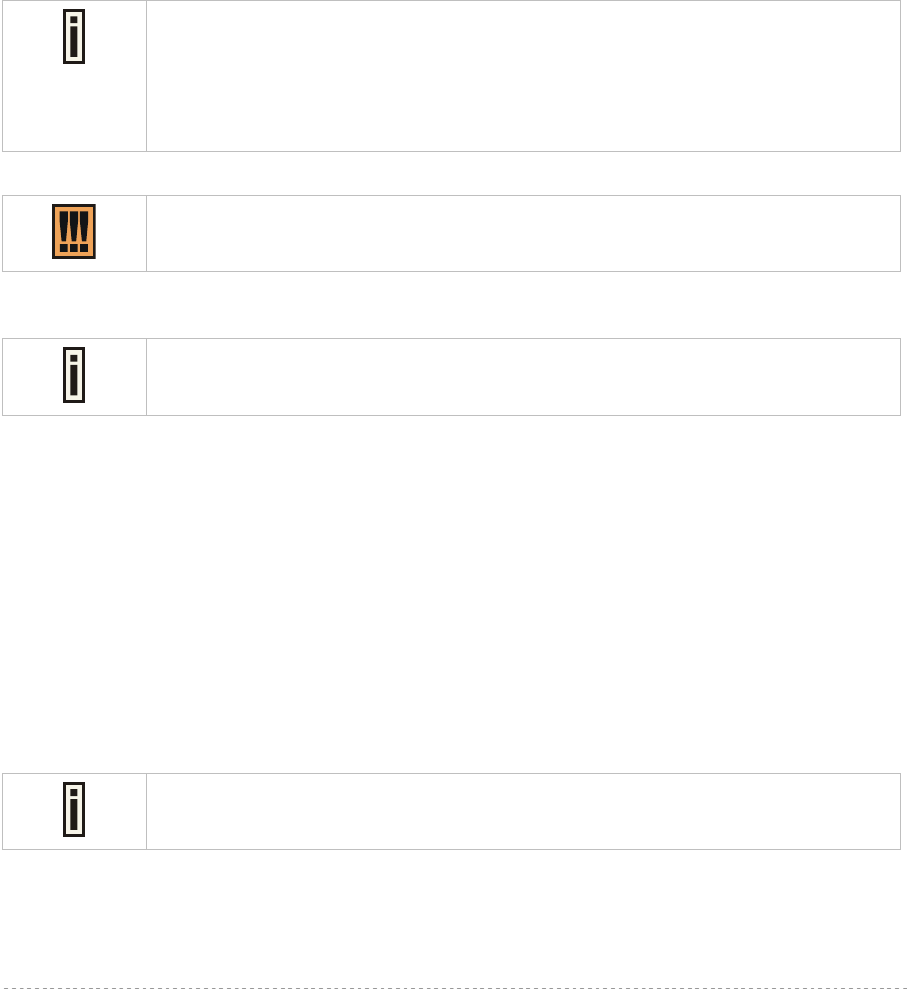
BW1254 User Guide v1.0 Nov. 2013
Page 109 of 184
Fragment Threshold – It specifies the maximum size for a packet before data is fragmented into
multiple packets. If you experience a high packet error rate, you may slightly increase the
fragmentation threshold. Setting the fragmentation threshold too low may result in poor network
performance. Only minor modifications of this value are recommended. The default value is
2347.[recommend]
Beacon Interval – the Beacon Interval value indicates the frequency interval of the beacon. A beacon
is a packet broadcast by the AP to synchronize the wireless network.
DCA – Enable or Disable DCA service. DCA can help to choose the best working channel
automatically. And static channel selection will be forbidden if DCA is enabled.
DCA(Dynamic Channel Allocation) solution automatically select the optimal operational frequency
channel when power up and periodically monitors the environment and adjusts for the best
operational frequency channel.
DCA threshold – specify the value (in minutes) of DCA threshold. This threshold is been used to
judge if there is no wireless users connected during this time. And if yes, BW1254 will monitor the
environment and adjust channel for the best operational one.
If wireless network environment is stable which means auto channel selection
needn’t do frequently, set a big value for DCA threshold to gain a stable wireless
users’ connection.
If wireless network environment changes continually, frequent auto channel
selection is needed. So set a relative small value for DCA threshold to let channel
change based on wireless environment.
Wireless users’ will be kicked off when DCA is processing (new operational
frequency channel takes effect).
DCA optional channel – specify the channels only in which auto channel selection (DCA) will choose
for reducing interference reference.
Only when DCA is enabled, DCA threshold and DCA optional channel will be
shown.
Preamble – if your wireless device supports the short preamble and you are having trouble getting it
to communicate with other 802.11b devices, make sure that it is set to use the long preamble.
Auto: using long preamble when there are clients not supporting short preamble connected ,
otherwise using short preamble. The default is Auto.[recommend]
Short: always using short preamble.
Long: always using long preamble.
Slot Time – specify the slot time policy when working in 2.4GHz band.
Auto: using long slot time when there are clients not supporting short slot time connection,
otherwise using short slot time. The default is Auto.[recommend]
Short: always using short slot time.
Long: always using long slot time.
To Maximize the compatibility with some 11b clients, set both Preamble and Slot
Time to long.
Change status or leave in the default state if no editing is necessary and click the Save button.
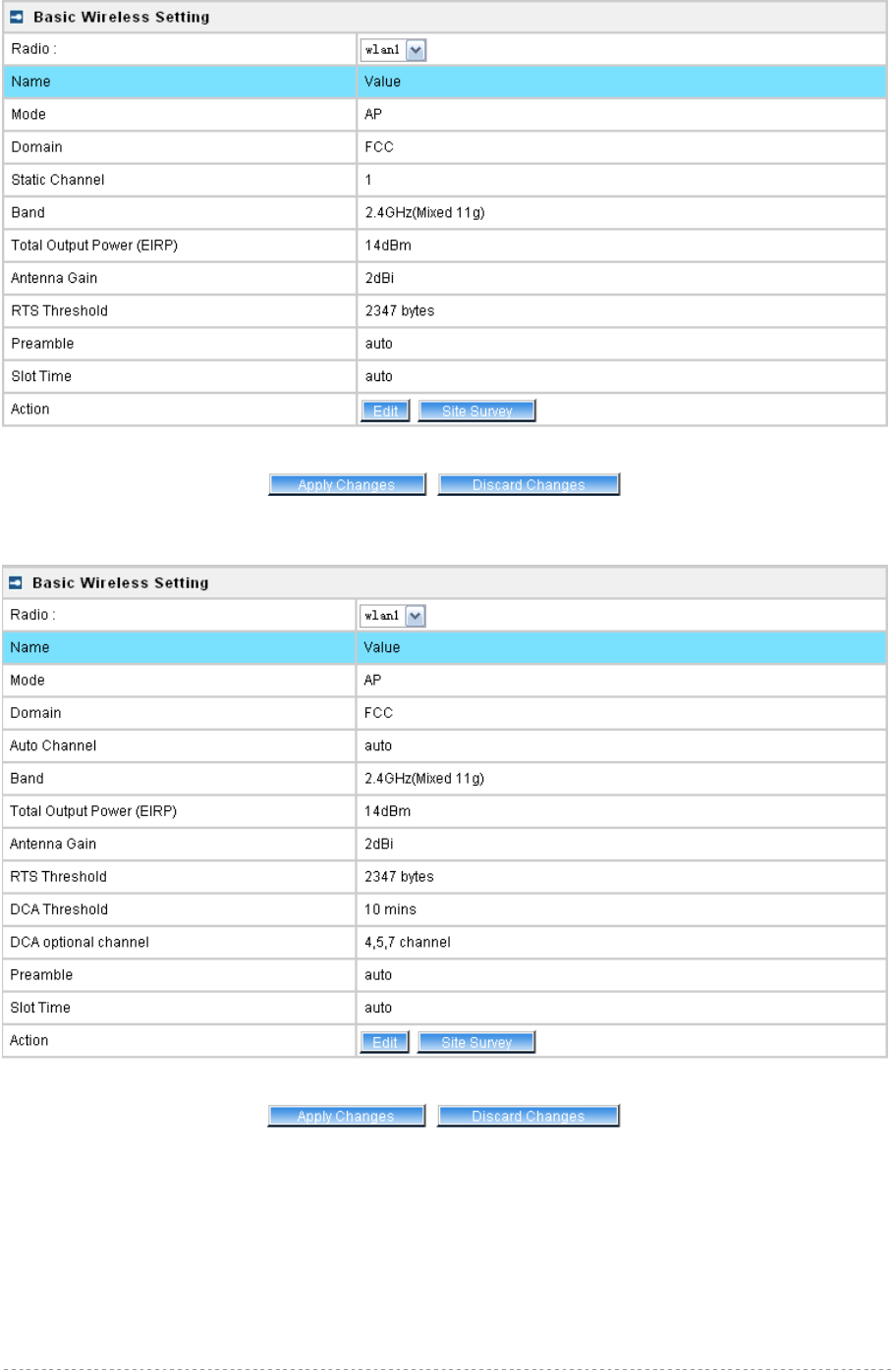
BW1254 User Guide v1.0 Nov. 2013
Page 110 of 184
Figure 186 – Apply or Discard Basic Wireless Settings with Static Channel selection
Figure 187 – Apply or Discard Basic Wireless Settings with DCA enabled
For such change of settings, the BW1254 needs to be restarted to apply all settings changes when
clicking Apply Changes. Request for reboot server appears:
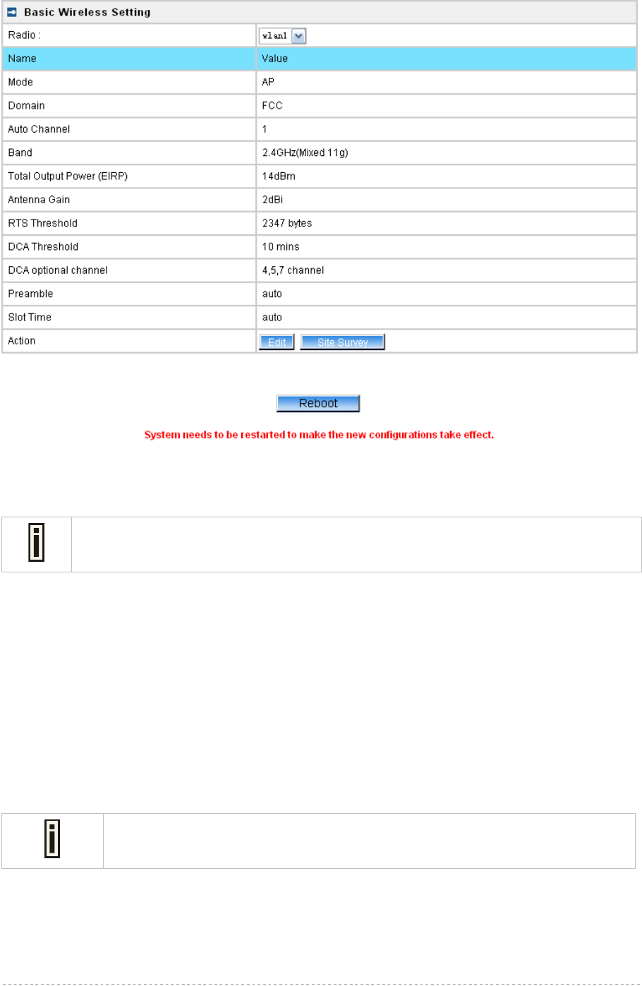
BW1254 User Guide v1.0 Nov. 2013
Page 111 of 184
Figure 188 – Reboot Server
Reboot – click the button to restart the server and apply the changes.
If there is no other settings needed to be modified, click the Reboot button to apply all
changes. If there are any other settings need to be changed, continuously to finish and
apply all changes and then click Reboot button to restart and take effect for all settings.
Wireless | Advanced
BW1254 supports Multiple BSSID (MBSSID) function. You can configure up to 16 BSSIDs on
BW1254 and assign different configuration settings to each BSSID. For wireless users, they can think
BW1254 as single AP with multi service supporting, including different security policy, different VLAN
ID, different authentication etc. All the BSSIDs are active at the same time that means client devices
can associate to the access point for specific service. Use the Wireless | Advanced menu to
configure properties related to Multiple BSSID, including configure SSID, Hidden SSID, VLAN, and
Security for each SSID.
Each BSSID can have its own SSID. In this case, Multiple BSSID is the same with
Multiple ESSID. Wireless users can think BW1254 as multiple virtual APs, each
supporting different service, and connects one SSID for the special services.
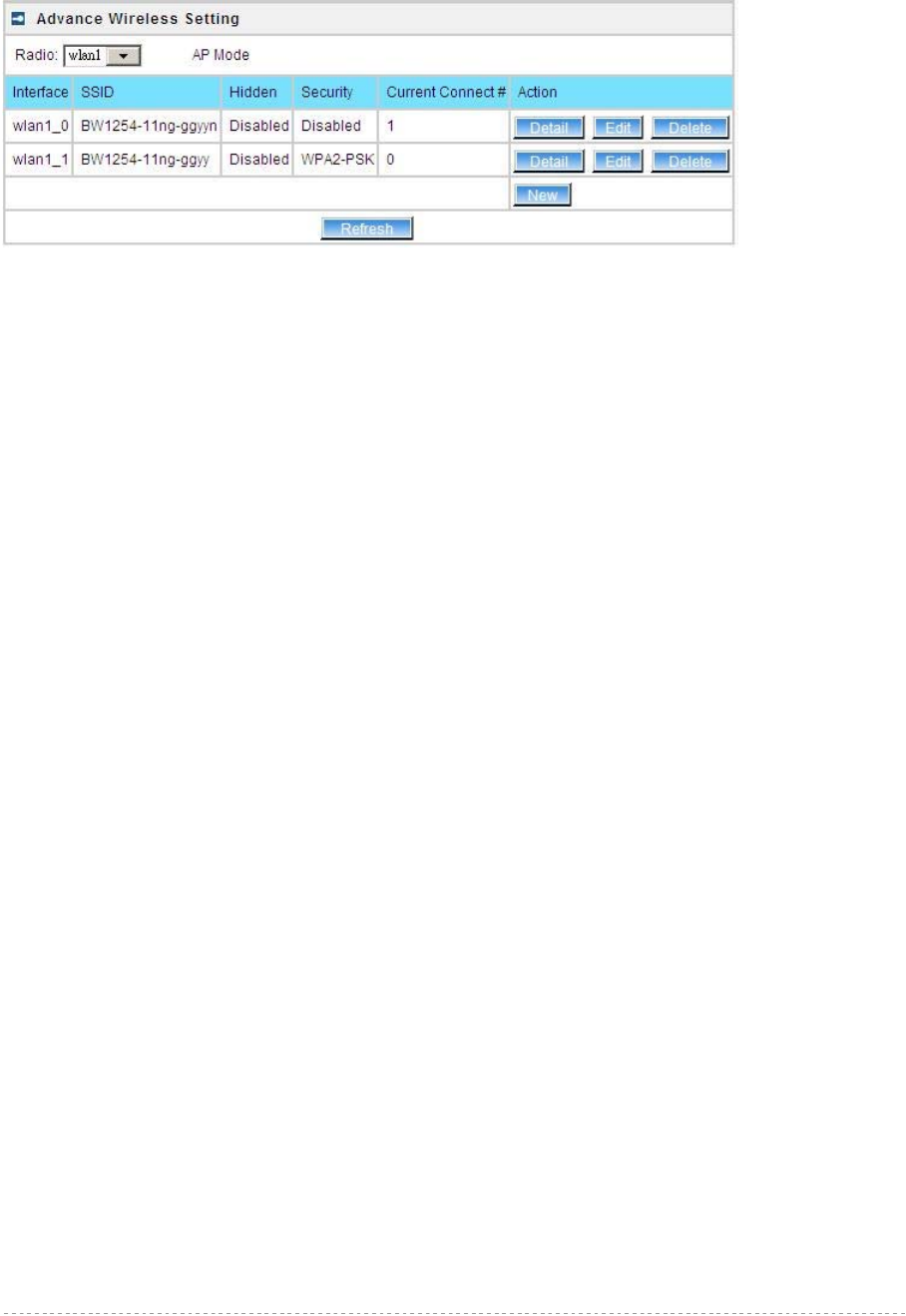
BW1254 User Guide v1.0 Nov. 2013
Page 112 of 184
AP Mode
If you configure AP mode, the page will be shown as below in Wireless | Advanced menu.
Figure 189 – Advanced Wireless Setting (AP Mode)
Radio – specify wireless interface to be configured. [wlan1(2.4G/wlan2(5G)]
Mode – show the current operation mode of this radio (AP or Bridge)
Interface – display the interface which corresponding to the SSID. Each Interface maps to a BSSID
SSID – SSID name for wireless client searching and associating.
Hidden – show the status of Hidden SSID feature[disable/enable]
Security – show which security policy is used for this MBSSID entry
Current Connect # – show the number of current wireless clients associate to this MBSSID
New – create a new MBSSID entry
Detail – show the detail information of this MBSSID entry
Edit – edit the selected MBSSID entry you want to configure
Delete – delete the selected MBSSID entry. When in AP mode, you can not delete the last entry
Refresh – rescan the WEB page to get newer information
Clicking New or Edit button to configure the SSID parameters. Describe as below:
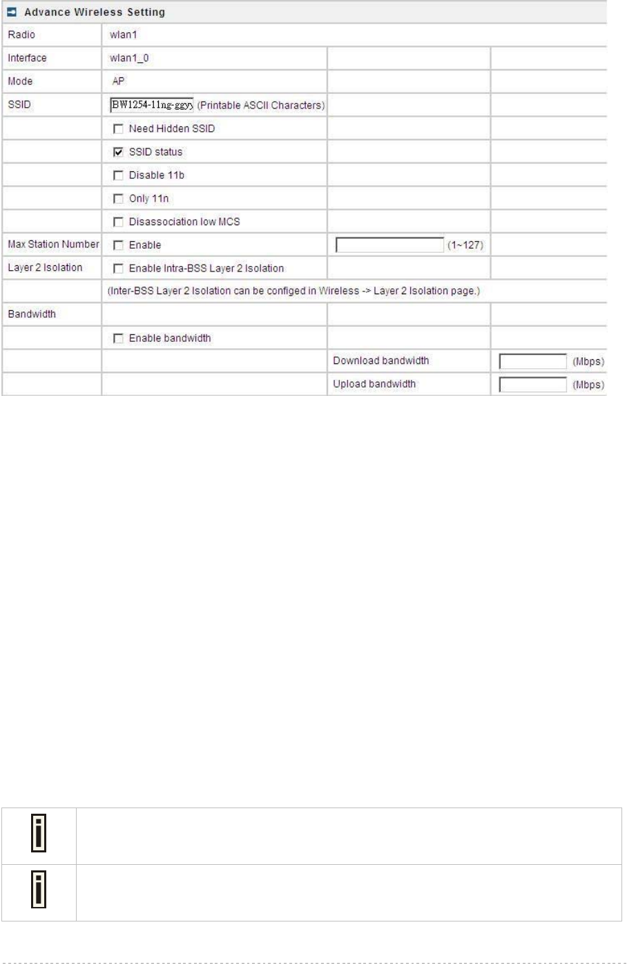
BW1254 User Guide v1.0 Nov. 2013
Page 113 of 184
Figure 190 – BSSID Setting -1
Radio – show the wireless interface is being configured.
Interface – show the current sub-interface.
Mode – show the operation mode of current radio.
SSID – a unique ID for your wireless network. It is case sensitive and must not exceed 32 characters.
The SSID is important for clients when connecting to the access point.
Need Hidden SSID – when enabled, the SSID of this Interface is invisible in the networks list
while scanning the available networks for wireless client (SSID is not broadcasted with its
Beacons). When disabled, the AP’s SSID is visible in the available network list
[enabled/disabled]. By default the Hidden SSID is disabled
SSID status – activated or deactivated the SSID. The default is activated SSID[check box].
Disable 11b – enable/disable 11b client connection. [check box] to enable the function.
Only 11n – only 802.11n client can connected to the SSID.
Disassociation low MCS – low MCS client won’t associate to the AP. [check box] to enable it.
Max Station Number – define maximum number of associated wireless client to this SSID. By default
the number is maximum 127 client can be associated to the AP without check box. Or check box to
enable limited client.[1~127]
Layer 2 Isolation – Specify the layer 2 isolation policy.
Enable Intra-BSS Layer 2 Isolation – when enabled, the clients that connect in this same BSS can’t
visit each other. By default the intra-BSS layer 2 isolation is disabled.
Intra-BSS layer2 isolation – which enable or disable client isolation under same SSID.
Inter-BSS layer2 isolation – which enable or disable client isolation between different
SSID.
Please go to Wireless | Layer 2 Isolation(Inter-BSS)
menu to configure inter-BSS layer 2 Isolation. Full layer 2 isolation need to set both
intra-BSS and inter-BSS layer 2 isolation in the AP mode.
Bandwidth – enable/disable upstream/downstream bandwidth control per SSID.

BW1254 User Guide v1.0 Nov. 2013
Page 114 of 184
Download bandwidth – specified the maximum downstream in Mbps controlled by the SSID.
Upload bandwidth – specify the maximum upstream in Mbps controlled by the SSID.
Figure 191 – Multiple BSSID Setting -2
VLAN – specify VLAN policy
Enable VLAN – when enabled, the outgoing packets from this SSID device will be tagged with
VLAN ID and 802.1p tag.
VLAN ID – configure VLAN ID for each Multiple SSID devices. Valid numbers are from 1 to
4094
802.1p Tag – configure 802.1p Tag for remote APC’s or Router’s QoS uses. Eight levels
selective, Background(1), Spare(2), Best Effort(0), Excellent Effort(3), Controlled Load(4),
Interactive Video(5), Interactive Voice(6), Network Contro(7)
VLAN ID and 802.1p tag must cooperate with remote Router or APC.
Interface priority – specify the traffic priority for this SSID interface, which is implemented according
to 802.11e EDCA and makes sure the wireless downlink QoS. This priority is based on SSID, which
means different BSSID can have different traffic priority and the traffic of the same SSID has the
same priority
This traffic priority only makes sure the priority of downlink (from AP to wireless
client).
8 levels priorities are supplied. 1, 2, 0, 3, 4, 5, 6, 7 is from lowest priority to highest
priority.
And if no special QoS is needed, leave priority to default (0). 0 means Best Effort
priority.
WMM –BW1254 support WMM wireless clients and implement WMM QoS with the WMM clients.
[enable]
ESS in Tunnel – Settings for ESS in tunnel. When enabled, BW1254 setup tunnel with remote AC for
passing through layer3 network.
Remote Server IP – IP address of remote AC product that setup tunnel with BW1254

BW1254 User Guide v1.0 Nov. 2013
Page 115 of 184
Figure 192 – Multiple BSSID Setting – 3
Security – specify the security policy
WEP – Wired Equivalent Privacy(WEP) is a security algorithm for IEEE 802.11 wireless networks.
WEP Key Index – select the default key Index to make it the Default key and encrypt the
data before being transmitted. All stations, including this MSSID Entry, always transmit data
encrypted using this Default Key. The key number (1, 2, 3, 4) is also transmitted. The
receiving station will use the key number to determine which key to use for decryption. If the
key value does not match with the transmitting station, the decryption will fail. The key value
is set in Wireless | WEP web page
802.1x – when selected, the MSSID entry will be configured as an 802.1x authenticator. It
supports multiple authentication types based on EAP (Extensible Authentication Protocol) like
EAP-TLS, EAP-TTLS, EAP-PEAP, EAP-SIM. The privacy will be configured as dynamic WEP
RADIUS Server Profile – select your RADIUS server profile
Please go to Network | RADIUS Server menu to configure your RADIUS server
profile or add a new profile, and please refer to Network | RADIUS Server for its
configuration.
Dynamic WEP Encryption – select whether using the dynamic 64-bits encryption, 128-bits
encryption or without encryption
Pass Through – when enabled, client can access network whether it passed 802.1x
authentication or not
Only when 802.1x enabled and dynamic key disabled this option can be enabled.
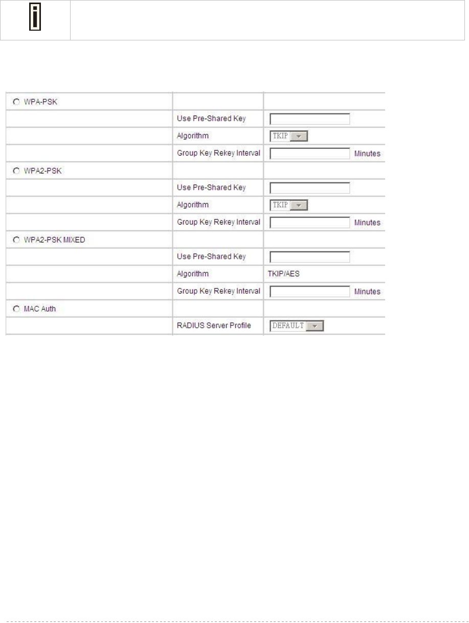
BW1254 User Guide v1.0 Nov. 2013
Page 116 of 184
WPA – Wi-Fi Protected Access, When selected, the encrypt method will be WPA with RADIUS
Sever
WPA2 – when selected, the security policy will be WPA2 with RADIUS server. In this mode, WPA
client is not permitted to connect
WPA2 MIXED – when selected, WPA2 client and WPA client are all permitted to connect
RADIUS Server Profile – select your RADIUS server profile
Please go to Network | RADIUS Server menu to configure your RADIUS server
profile or add a new profile, and please refer to Network | RADIUS Server for its
configuration.
Algorithm – choose WPA algorithm (TKIP, AES)
Group Key Rekey Interval – specify amount of minutes and WPA automatically will generate a
new Group Key
Figure 193 – Multiple BSSID Setting – 4
WPA-PSK – when selected, the encrypt method will be WPA without RADIUS server
WPA2-PSK – when selected, the security policy will be WPA2 PSK without RADIUS server. In
this mode, only WPA2 PSK client can connect with AP and WPA PSK client is not permitted to
connect
WPA2-PSK MIXED – when selected, WPA2 PSK and WPA PSK clients are all permitted to
connect with AP
Use Pre-Shared Key –specify more than 8 characters and less than 64 characters for WPA
with pre-shared key encryption
Algorithm – choose WPA algorithm (TKIP, AES)
Group Key Rekey Interval –specify amount of minutes and WPA automatically will generate
a new Group Key
MAC Auth – when selected, the MAC address of wireless client will be passed to RADIUS server
for PAP authentication when it connects with BW1254. The MAC address of wireless client acts
as username and password
RADIUS Server Profile – select the default radius server name
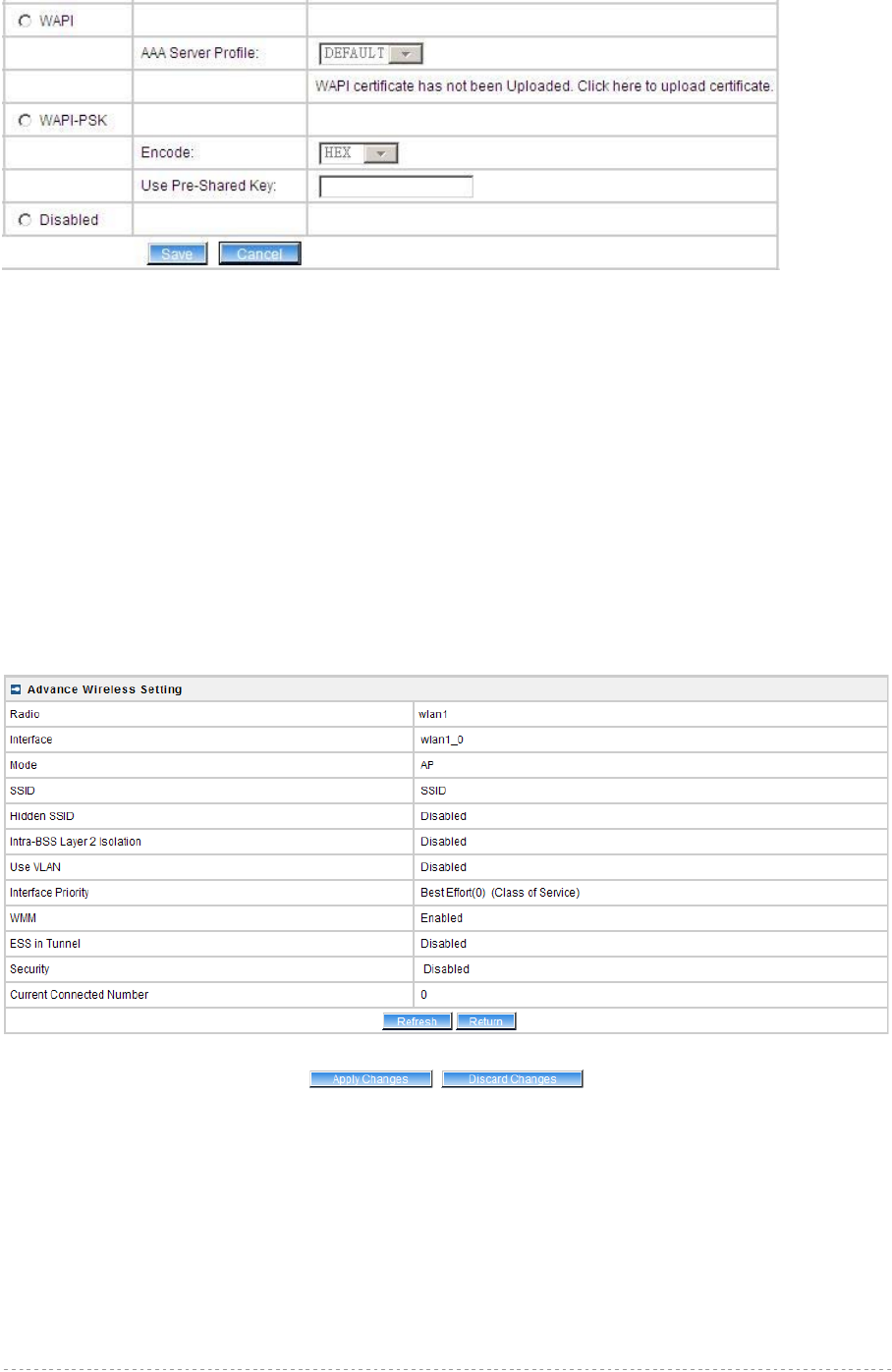
BW1254 User Guide v1.0 Nov. 2013
Page 117 of 184
Figure 194 – Multiple BSSID Setting – 5
WAPI – WLAN Authentication and Privacy Infrastructure (WAPI) is a Chinese National Standard for
wireless LAN(GB15629.11-2003).(Only for China)
It needs to upload WAPI certificate.
AAA Server Profile – select your RADIUS server profile
WAPI-PSK –the encrypt method will be WAPI without RADIUS server
Encode – Pre-shared key encode.[HEX/ASCII]
Use Pre-Shared key – specify more than 8 characters and less than 64 characters for WPA
with pre-shared key encryption
Disabled – when selected, you don’t select any security policy
Change status or leave in the default state if no editing is necessary and click the Save button.
Figure 195 –Apply or Discard the advanced Settings in AP mode
For each change of settings, the BW1254 needs to be restarted to apply all settings changes when
clicking Apply Changes. Request for reboot server appears:
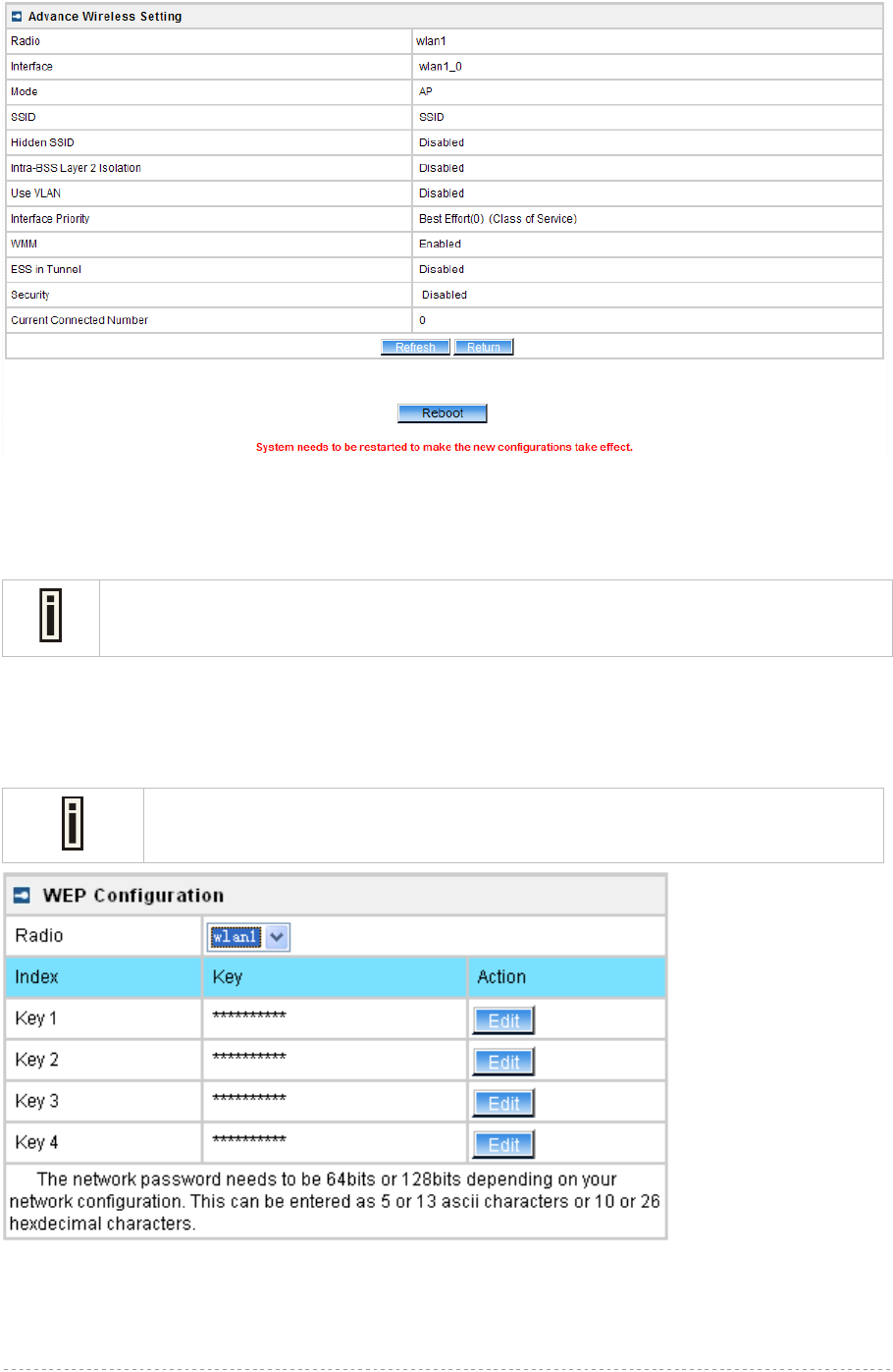
BW1254 User Guide v1.0 Nov. 2013
Page 118 of 184
Figure 196 – Reboot information
Reboot – click the button to restart the server and apply the changes.
If there is no other settings needed to be modified, click the Reboot button to apply all
changes. If there are any other settings need to be changed, continuously to finish and
apply all changes and then click Reboot button to restart and take effect for all settings.
Wireless | WEP
Use the Wireless | WEP menu to configure static WEP settings.
This menu only set static WEP key value related with 4 key indexes. Enable or
Disable static WEP is in the Wireless | Advance menu.
Figure 197 – WEP Settings
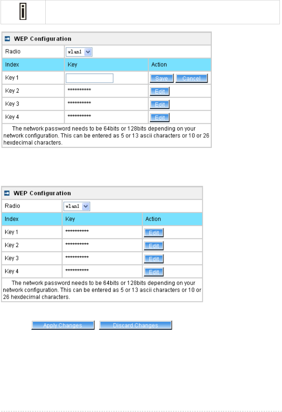
BW1254 User Guide v1.0 Nov. 2013
Page 119 of 184
Radio –show the wireless interface.
Click Edit to edit the existing wepkey1 to wepkey4.
By default, four WEP keys are all set to “aaaaa” (ascii characters) or “6161616161”
(hexadecimal characters). They can be modified according to requirement.
Figure 198 – Edit WEP Key
Change status or leave in the default state if no editing is necessary and click the Save button.
Figure 199 –Apply or Discard WEP Configuration
For each change of settings, the BW1254 needs to be restarted to apply all settings changes when
clicking Apply Changes. Request for reboot server appears:
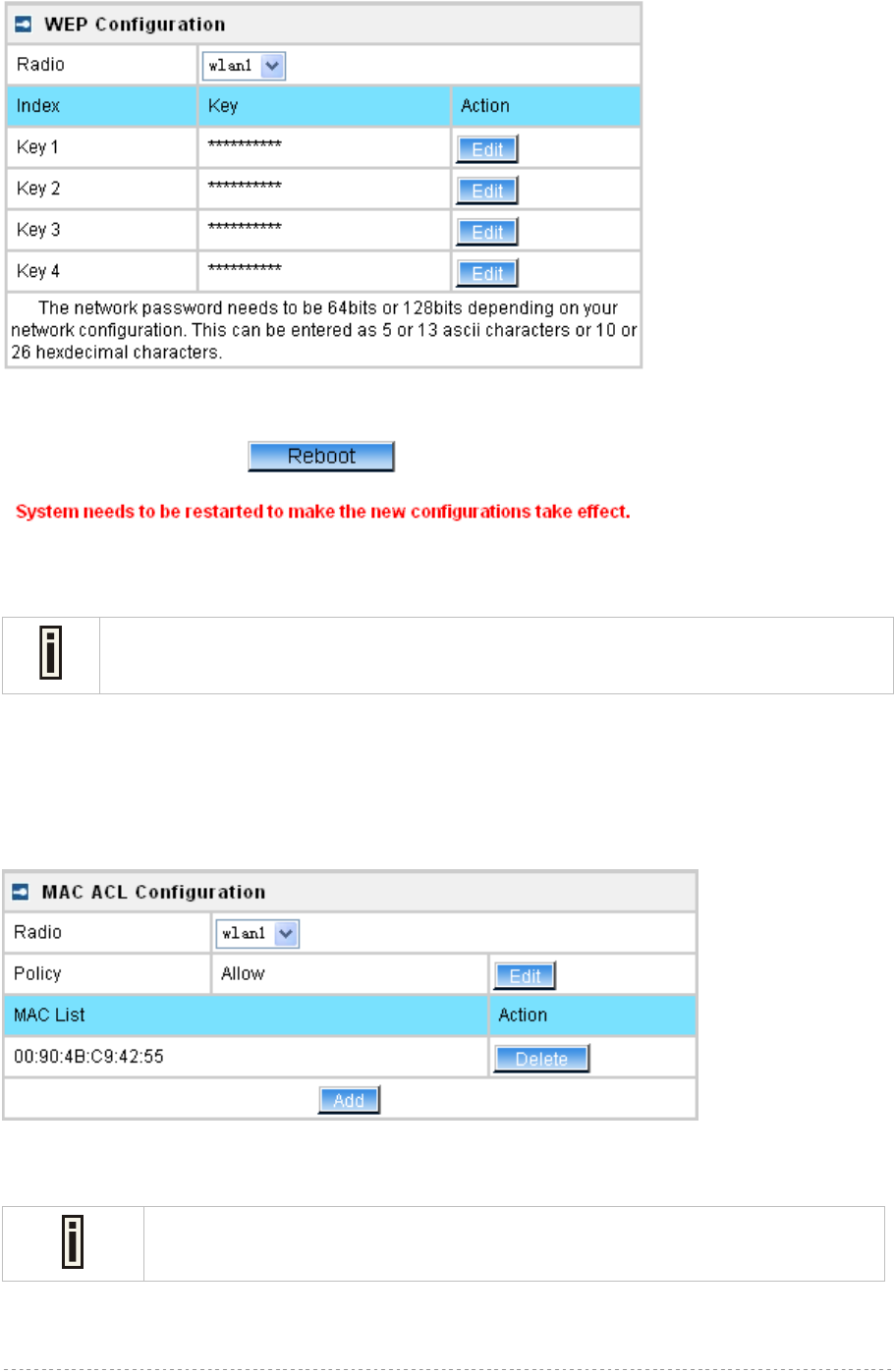
BW1254 User Guide v1.0 Nov. 2013
Page 120 of 184
Figure 200 – Reboot information
Reboot – click the button to restart the server and apply the changes
If there is no other settings needed to be modified, click the Reboot button to apply all
changes. If there are any other settings need to be changed, continuously to finish and
apply all changes and then click Reboot button to restart and take effect for all settings.
Wireless | MAC ACL
Use the MAC ACL service to control the default access to the wireless interface of the BW1254 or
define special access rules for mobile clients. Configure the ACL using the Wireless | MAC ACL
menu:
Figure 201 – MAC ACL Service
Radio – show the wireless interface.
The wireless interface which is Bridge mode hasn’t MAC ACL settings.
Policy – click the edit button to choose Allow, Deny or disable the access control service on device.
By default the ACL service is disabled and all wireless clients connecting to the BW1254 are allowed
(no ACL rules are applied to the wireless clients)
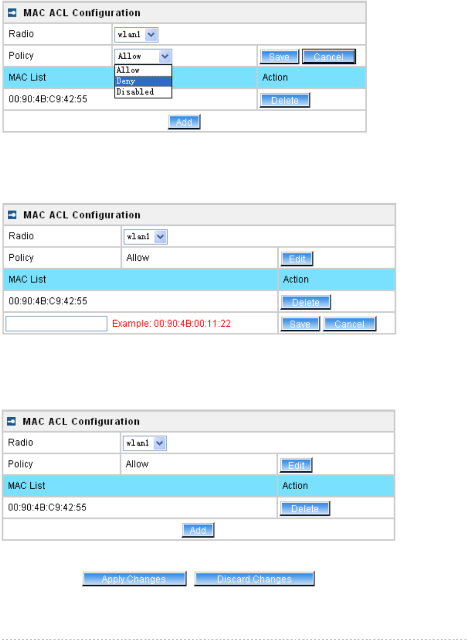
BW1254 User Guide v1.0 Nov. 2013
Page 121 of 184
Select Allow means only the wireless clients whose MAC are listed in the MAC List would be
permitted to access this AP. Other wireless client cannot access this AP.
Select Deny means only the wireless clients whose MAC are listed in the MAC List would be
prevented from accessing. Other wireless clients can access this AP.
Select Disabled means no ACL service.
Figure 202 – MAC ACL settings
You must create MAC List to work with Policy setting. The access control list is based on the
network device’s MAC address. In the MAC ACL Configuration table, you only need to specify the
MAC address of wireless client. Click the Add button to create a new MAC entry:
Figure 203 – Add MAC entry
MAC Address – enter the physical address of the network device you need to (MAC address). The
format is a list of colon separated hexadecimal numbers (for example: 00:90:4B:00:11:22)
Save – click the button to save the new MAC entry
Figure 204 – Apply or Discard MAC ACL Configuration Changes
Apply Changes – to save all changes made in the interface table at once
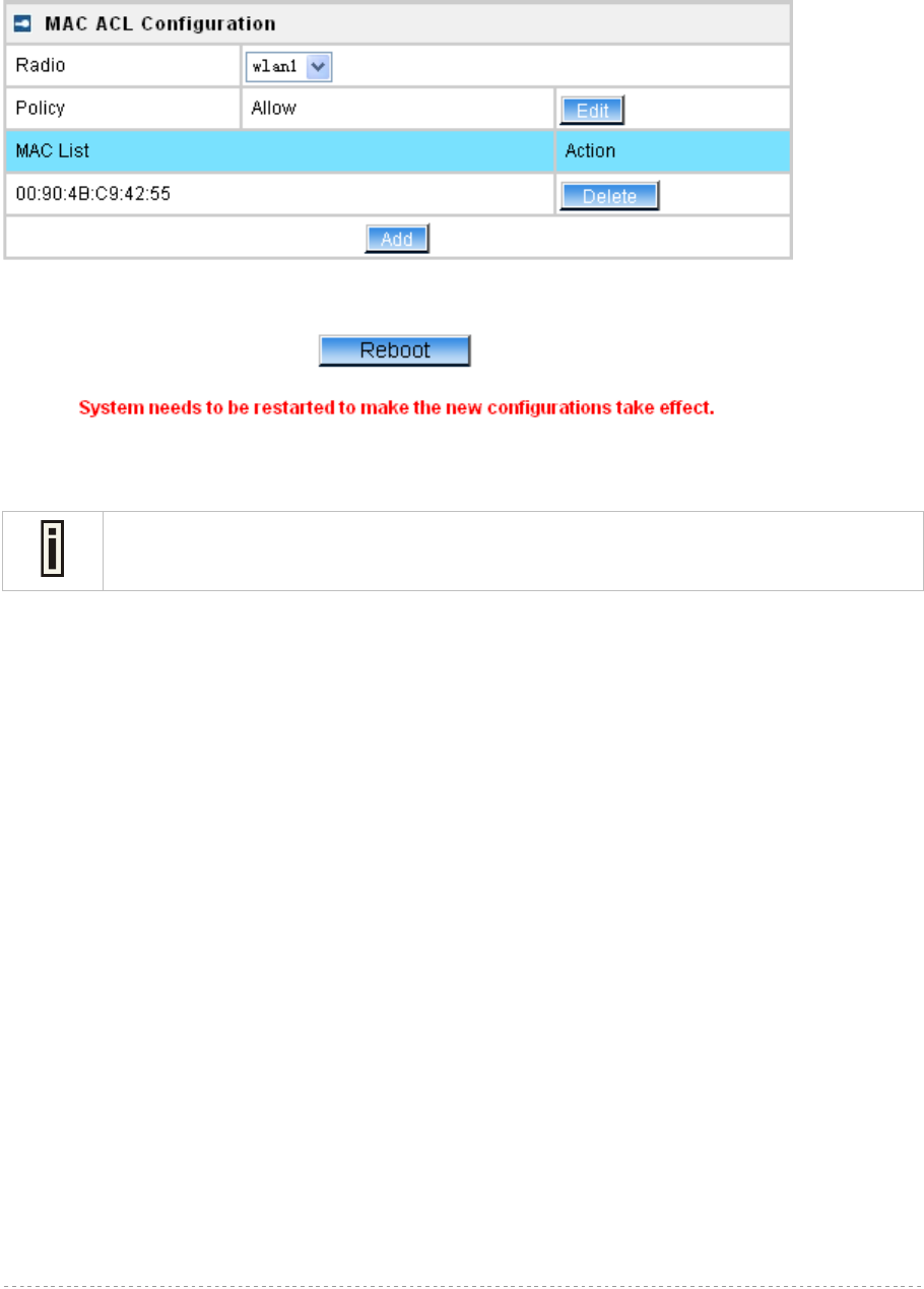
BW1254 User Guide v1.0 Nov. 2013
Page 122 of 184
Discard Changes – restore all previous values
For such change of settings, the BW1254 needs to be restarted to apply all settings changes when
clicking Apply Changes. Request for reboot server appears:
Figure 205 – Reboot Server
Reboot – click the button to restart the server and apply the changes
If there is no other settings needed to be modified, click the Reboot button to apply all
changes. If there are any other settings need to be changed, continuously to finish and
apply all changes and then click Reboot button to restart and take effect for all settings.

BW1254 User Guide v1.0 Nov. 2013
Page 123 of 184
User
User | Users
The User | Users menu shows the statistics of connected users. The user can be monitored and
managed such as drop from the network.
Figure 206 – User’s statistics
User – show the connected client’s MAC address
Interface – show which BSS the client connected to
User IP – IP address, from which the user’s connection is established [digits and dots]
Authed – indicate this client is authenticated or not
WEB Auth/L2 Auth – show the authentication method which user uses to connect
Time Length – session duration since the user login [hh:mm:ss]
Idle Time – amount of user inactivity time [hh:mm:ss]
Action – view the statistics or kickoff the user.
Detail – click on user details to get more information about the client:
Kickoff – logout the user.
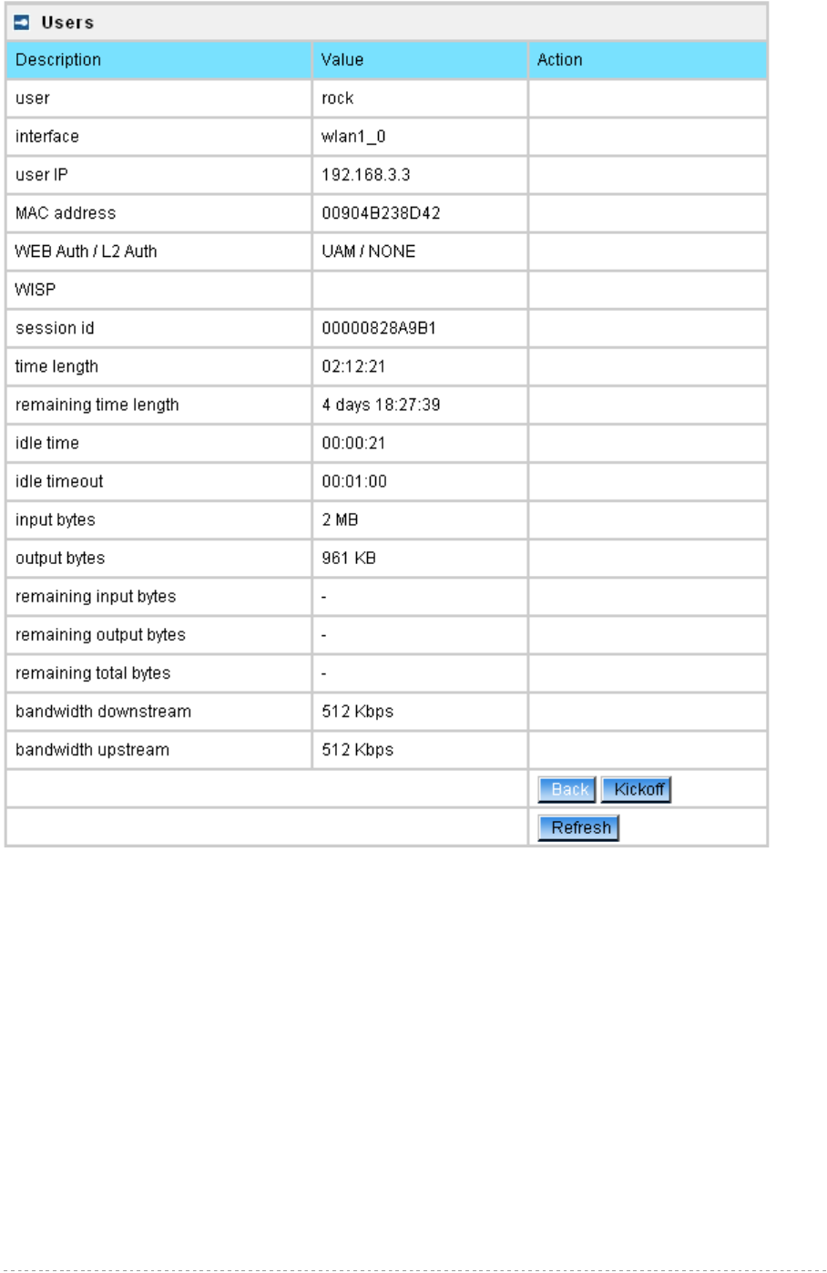
BW1254 User Guide v1.0 Nov. 2013
Page 124 of 184
Figure 207 – User’s Details
User – login user name
interface – the interface that wireless client associated.
User IP – the IP address of wireless client.
MAC address – hardware address of the network device from which the user is connected
WEB Auth/L2 Auth – show web authentication and layer2 authentication status, layer2 authentication
include all supported EAP type of 802.1x auth and MAC auth
WISP – WISP domain name where the user belongs
Session ID – the unique user’s session ID number. This can be used for troubleshooting purposes
Remaining Time Length – remaining user’s session time [hh:mm:ss]. Session time for user is
defined in the RADIUS Server
Idle time – specify current idle time.
Idle Timeout – specify the time of user idle timout [hh:mm:ss]. When reach the time, the user will be
logged out automatically.
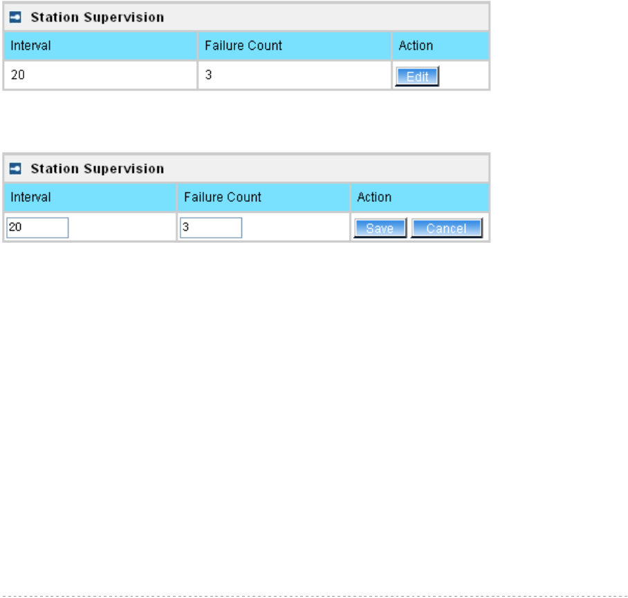
BW1254 User Guide v1.0 Nov. 2013
Page 125 of 184
Input Bytes – amount of data in bytes which the user network device has received [Bytes]
Output Bytes – amount of data in bytes, transmitted by the user network device [Bytes]
Remaining Input/Output Bytes – user session remaining input/output bytes. WISPr Operator can
define the user session in bytes. Remaining bytes is received from RADIUS [Bytes/unlimited]
Remaining Total Bytes –user session remaining total bytes. WISPr Operator can define the user
session in bytes. Remaining bytes is received from RADIUS [Bytes/unlimited]
Bandwidth Downstream/Upstream – user upstream and downstream bandwidth [in bps]
Back – returns to connect client’s statistics list
Kickoff – click this button to logout the user from access point.
Refresh – click the button to refresh users’ statistics
User | Station Supervision
The Station Supervision function is used to monitor the connected host station availability. This
monitoring is performed with ping. If the specified number of ping failures is reached (failure count),
the user is logged out from the BW1254.
Figure 208 – Station Supervision
To adjust the ping interval/failure count, click the Edit button.
Figure 209 – Edit Station Supervision
Interval – define interval of sending ping to host [in seconds]
Failure Count – failure count value after which the user is logged out from the system
Save – save station supervision settings
Cancel – cancel changes
Change status or leave in the default state if no editing is necessary and click the Save button.
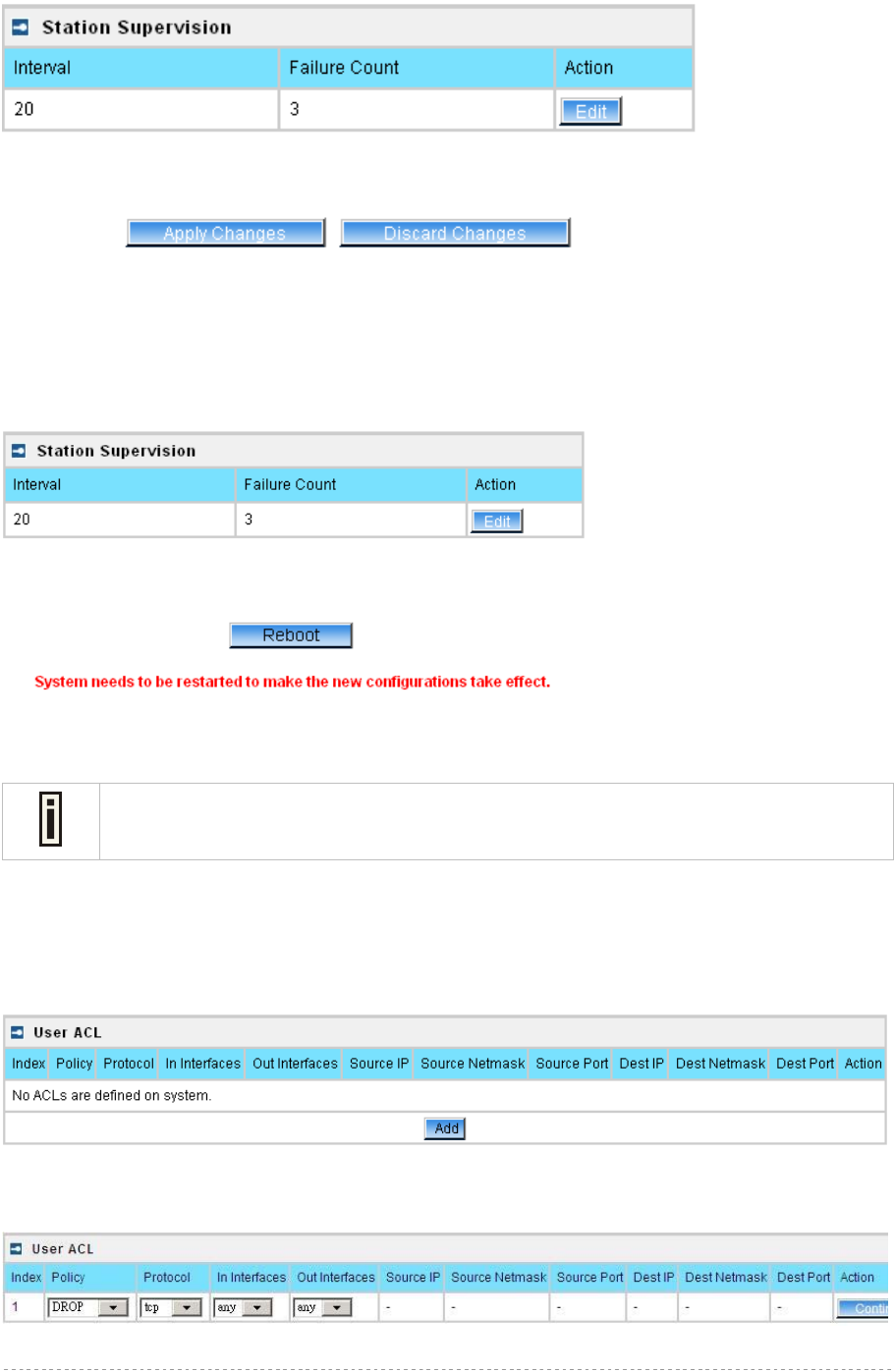
BW1254 User Guide v1.0 Nov. 2013
Page 126 of 184
Figure 210 –Apply or Discard Station Supervision Changes
Apply Changes – to save all changes at once
Discard Changes – restore all previous values
For such change of settings, the BW1254 needs to be restarted to apply all settings changes when
clicking Apply Changes. Request for reboot server appears:
Figure 211 – Reboot Server
Reboot – click the button to restart the server and apply the changes
If there is no other settings needed to be modified, click the Reboot button to apply all
changes. If there are any other settings need to be changed, continuously to finish and
apply all changes and then click Reboot button to restart and take effect for all settings.
User | User ACL
User ACL provide high flexibility for administrator to define the rules for BW1254 to filter the packets
which will forward or masquerade by it.
Figure 212 – User ACL
To add a new rule, just click the Add button.
Figure 213 – Create a new rule (first step)
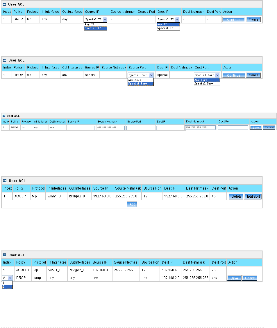
BW1254 User Guide v1.0 Nov. 2013
Page 127 of 184
First step select the rule policy [drop/accept/masquerade] to deal with packet and the packet type
[all/TCP/UDP/ICMP] and which interface the rule will act on.
Policy – define the policy of client through the access point. It supports three types of rules: DROP,
ACCEPT and MASQUERADE. The appropriate policy defines what to do if the data packet received
matches the rule
Protocol – network protocol which the rule affects. Can be specified as one of “TCP/UDP/ICMP” or
“any”
In Interface – the data packet to the current interface must obey the rule
Out Interface – the data packet from the current interface must obey the rule
Figure 214 – Create a new rule (second step)
Second step select the type of source IP and destination IP [special IP/any IP].
Figure 215 – Create a new rule (third step)
Third step choose the type of source port and destination port [any port/special port].
Figure 216 – Create a new rule (fourth step)
Fourth step, fill out the source IP address and destination IP address (including IP address and net
mask, if you choose “any IP” in second step, you need not fill out the IP address); fill out the source
port and destination port (if you select any port in third step or select protocol ICMP/all, you need not
fill out the port).
Figure 217 – Create a new rule (fifth step)
After complete the rule configuration, click the “apply changes” button to save your configuration.
You can also re-order your rules if you have many rules configured and arrange the priority of them.
The rule with index 1 has the highest priority; with index 2 has the second high priority and so on.
Figure 218 – re-order rules
Click Edit Sort button of one rule to re-order its priority and then select the index number, click Save
button to save your changes.
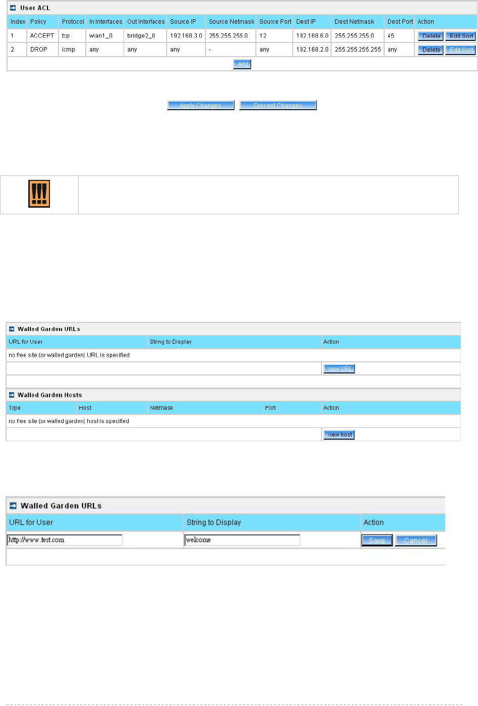
BW1254 User Guide v1.0 Nov. 2013
Page 128 of 184
Figure 219 –Apply or Discard User ACL Changes
Apply Changes – to save all changes of User ACL at once
Discard Changes – restore all previous values
Please be careful to use the DROP policy. For example, if DROP tcp for any
source IP, BW1254 web UI will not be accessed.
User | Walled Garden
The walled garden is an environment that controls the user's access to Web content and services. It
is to define a free, restricted service set for a user do not logged into the system. Use the User |
walled garden menu to view or change the free URLs or hosts:
Figure 220 –Walled Garden
New URL – click the new URL button and enter the new URL and its description. Save entered
information by clicking the update button:
Figure 221 – Add New URL part 1
URL for User – define full URL address. Ex:[http://www.test.com]
String to Display – site description visible to user listed on the welcome and login page:
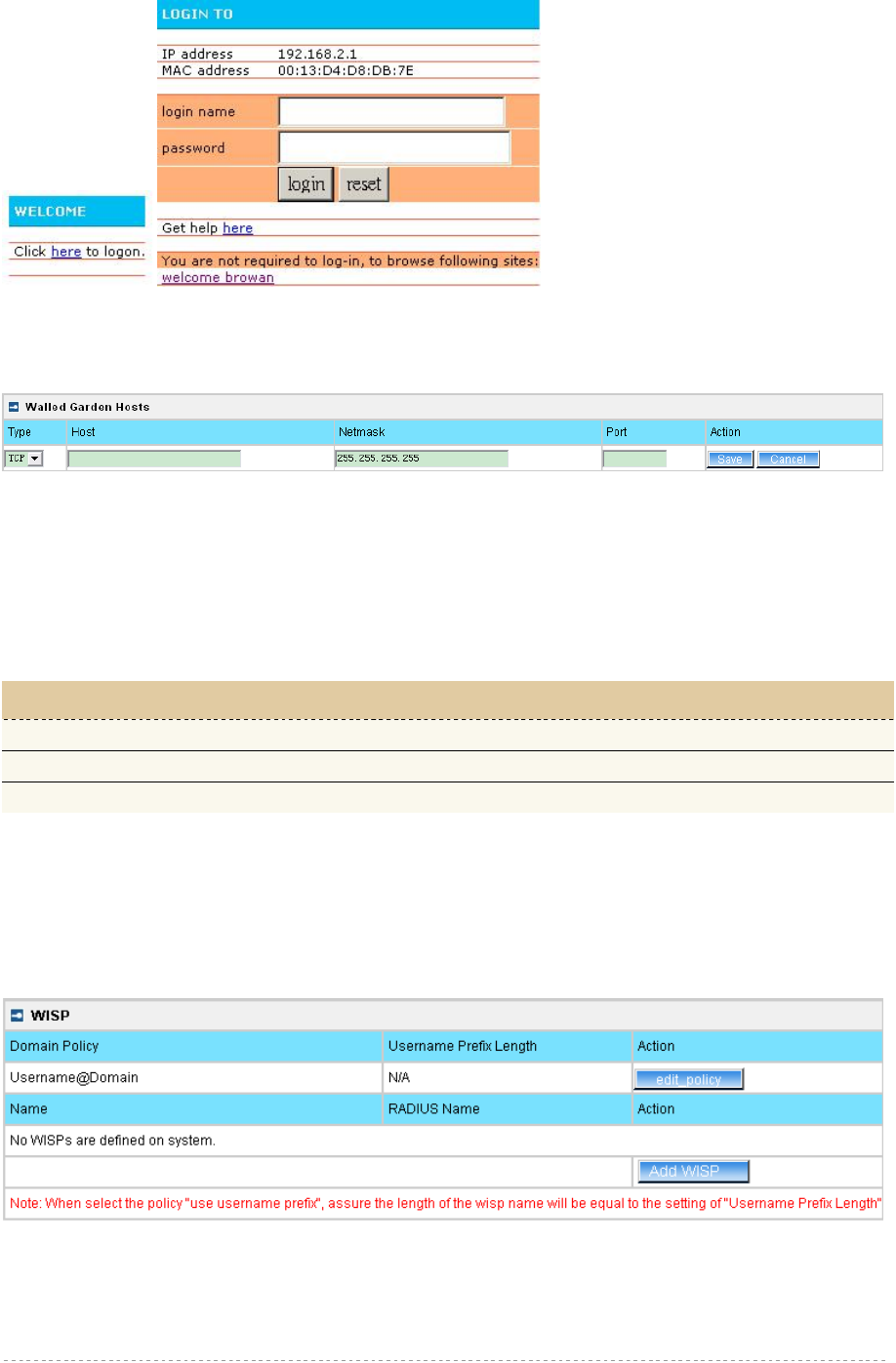
BW1254 User Guide v1.0 Nov. 2013
Page 129 of 184
Figure 222 – Walled Garden link in the Welcome Page
New Host – If you need to define hosts (web servers) for walled garden, specify hosts by clicking the
new host button and click the update button:
Figure 223 – Walled Garden Host
Type –select the data traffic protocol for host server [TCP/UDP].
Host – Web server address [IP address or host name].
Netmask – enter the network mask to specify the host servers network.
Port – network port, which is used to reach the host [1-65535]. For standard protocols use the default
ports:
Protocol Port
HTTP 80
HTTPS 443
FTP 21
User | WISP
Different WISPs (Wireless Internet Service Providers) can be associated with appropriate RADIUS
servers and device interfaces using the User | WISP menu:
Figure 224 – WISP Menu
Domain policy means BW1254 use which policy to fetch WISP name from user name then to judge
user belong which domain.
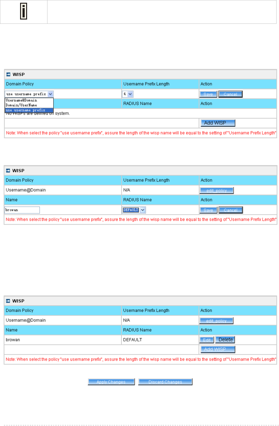
BW1254 User Guide v1.0 Nov. 2013
Page 130 of 184
Up to 32 WISP entries can be defined using the User | WISP menu.
The owner can use three policies to judge the WISP name from user name:
1. username follow the format: username@WISPdomain
2. username follow the format: WISPdomain/username
3. use prefix of username as wisp name, the range of prefix length is from 2 to 6
Figure 225 – Domain Policy
Add WISP – click to define WISP for RADIUS server
Figure 226 – Define New WISP
Name – new WISP domain name [string, up to 256 symbols, no space, dot or dash allowed]
RADIUS Name – select RADIUS for new WISP from list box [non editable]
Save – click the button to save the new WISP
Cancel – restore all previous values
Figure 227 – Apply or Discard Changes of WISP settings
BW1254 needs to be restarted to apply all settings changes when clicking Apply Changes. Request
for reboot server appears:
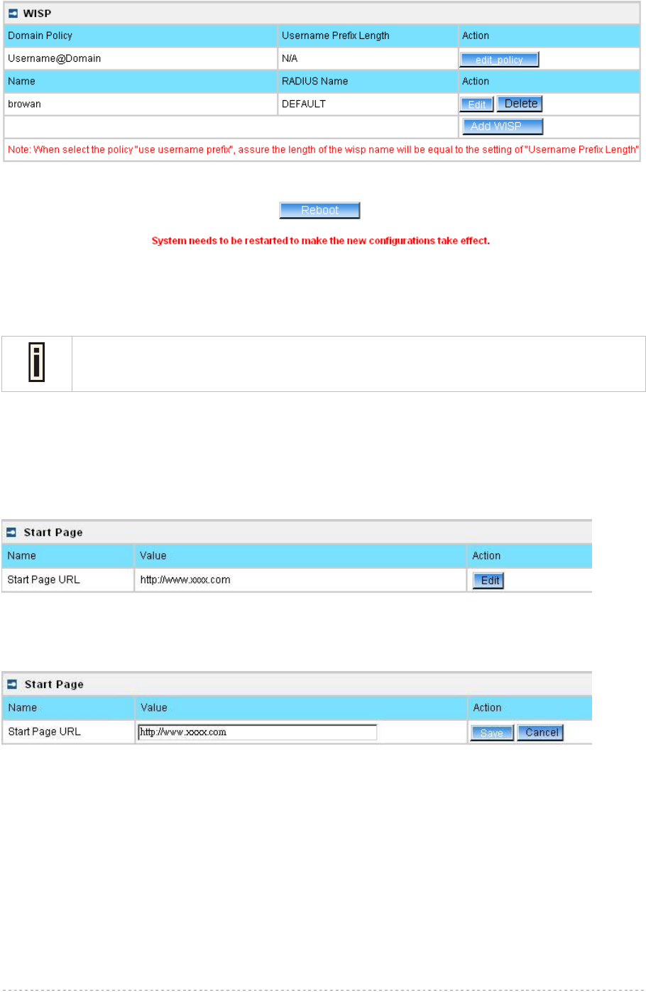
BW1254 User Guide v1.0 Nov. 2013
Page 131 of 184
Figure 228 – Reboot information
Reboot – click the button to restart the server and apply the changes.
If there is no other settings needed to be modified, click the Reboot button to apply all
changes. If there are any other settings need to be changed, continuously to finish and
apply all changes and then click Reboot button to restart and take effect for all settings.
User | Start Page
The start page is the default web page where users will be redirected after log-on. This value will be
overwritten by the WISP RADIUS attribute no.4 “Redirection-URL” if provided in the authentication
response message. Use the User | Start Page menu to view or change the start page URL:
Figure 229 – Start Page
The administrator can change the start page by clicking the Edit button. The value entry field will
change into an editable field:
Figure 230 – Edit Start Page
Value – enter new redirection URL of start page in valid format [http://www.startpageurl.com]
Save –click the button to save new settings
Cancel – restores all previous values
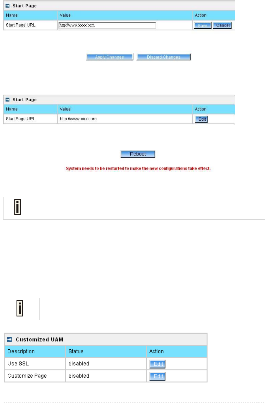
BW1254 User Guide v1.0 Nov. 2013
Page 132 of 184
Figure 231 – Apply or Discard Changes of Start Page
BW1254 needs to be restarted to apply all settings changes when clicking Apply Changes. Request
for reboot server appears:
Figure 232 – reboot device
Reboot – click the button to restart the server and apply the changes.
If there is no other settings needed to be modified, click the Reboot button to apply all
changes. If there are any other settings need to be changed, continuously to finish and
apply all changes and then click Reboot button to restart and take effect for all settings.
User | Customized UAM
Customized UAM let owner upload their own login and logout page to BW1254 to apply with
enterprise style or do advertisements.
User customized page is based on HTML.
BW1254 support internal and external customized UAM. Internal means user can upload their html
login and logout page to BW1254. External means BW1254 will go to an external web server to fetch
login and logout page the local and push to web login client.
Please contact with BROWAN if you need the internal customized UAM template
sample.
Customized UAM in default is disabled. Click the Edit button on the setting you need to change:
Figure 233 – Customized UAM page
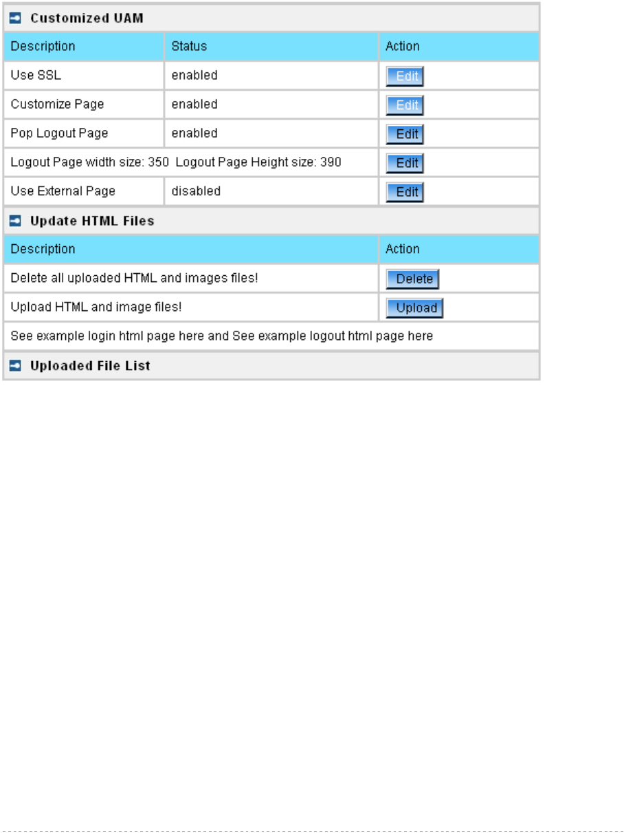
BW1254 User Guide v1.0 Nov. 2013
Page 133 of 184
Use SSL – select enable or disable to use SSL encryption for the HTTP session of the user login
page
Customize Page – enable the configuration if you want to use customized UAM function
After successfully enabled customized UAM configuration, this configuration page will be extended to
the follow page which includes three columns.
Figure 234 – Customized UAM enabled
First is Customized UAM status configuration:
Pop Logout Page – after user successful web login, if this item is enabled, BW1254 will pop out a
logout page for user. In default this setting is enabled if customized page is enabled
Logout Page’s Dimension – for the difference of logout page’s dimension which make by customer,
BW1254 will use this data to pop out user’s customized logout page
Use External Page – if this item is enabled, BW1254 will fetch login and logout page from an external
web server
Second is update html files, for user delete or upload login and logout pages. There also has two URL
point to example page in html format for login and logout page which user can reference to make their
own pages.
The third is uploaded file list, where user can find which files have been uploaded.
Press upload button on second column will coming into upload files pages:
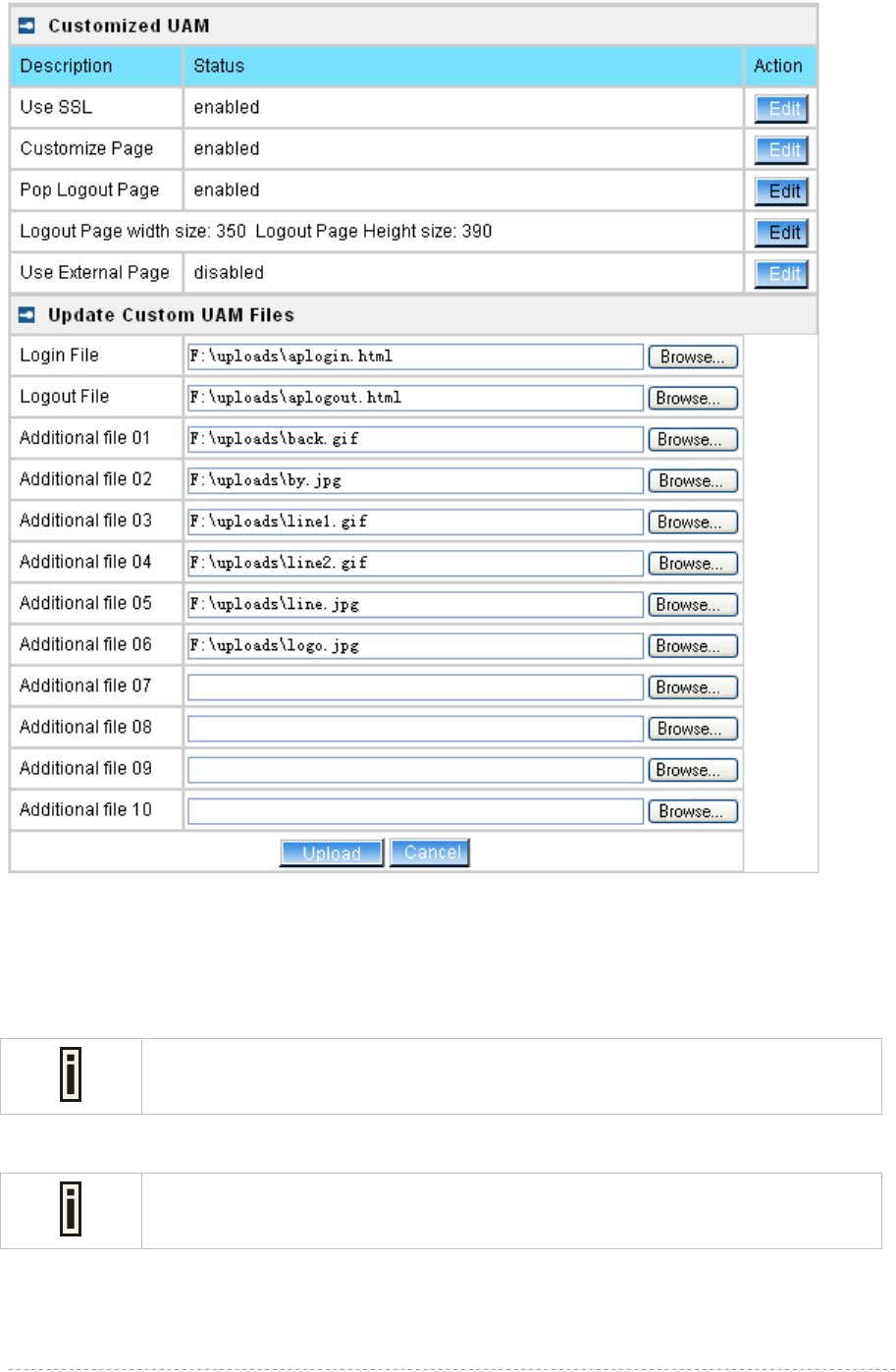
BW1254 User Guide v1.0 Nov. 2013
Page 134 of 184
Figure 235 – Upload Pages
Login File is for customized login page; Logout File is for customized logout page.
Additional file 01~10 is for uploading picture and CSS files. Current support picture file format is JPG,
GIF, PNG and CSS.
After select the file you want, press upload button and the files will upload to BW1254. after
successful upload files, you can see the page below:
Picture and CSS files name need be consistent with your login or logout html
pages. The login and logout html file can be what ever you want.
Don’t forget fill out the Logout page’s dimension, or logon user maybe can only
see part of your logout page.
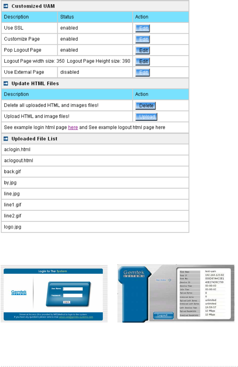
BW1254 User Guide v1.0 Nov. 2013
Page 135 of 184
Figure 236 – Flash upload files OK
After successful flash the files, uploaded files will appear in uploaded file list.
Next is an example for customized login and logout page.
Figure 237 – Example login and logout page
For external page, enabled the “Use External Page” as below.
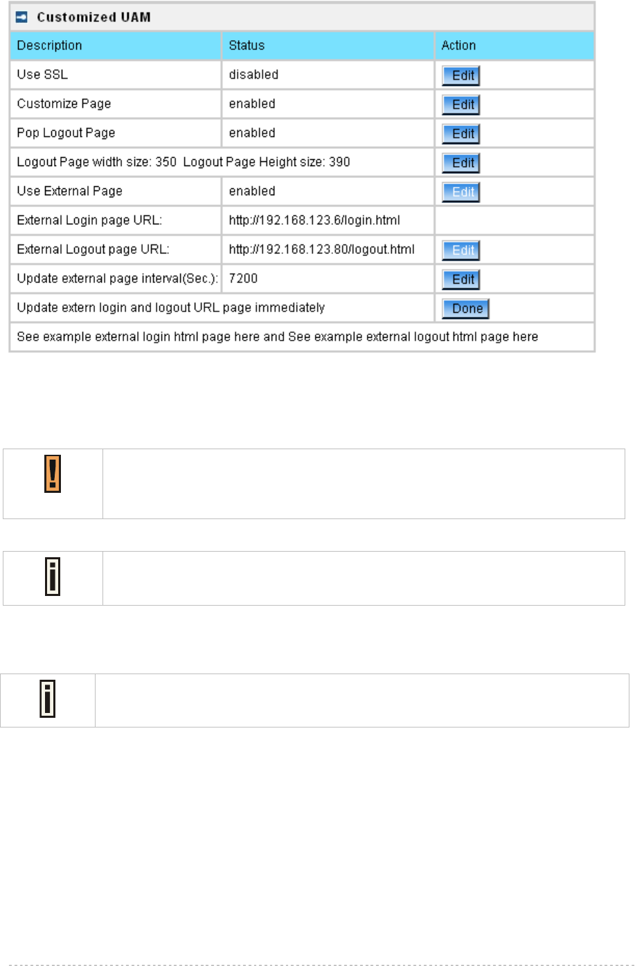
BW1254 User Guide v1.0 Nov. 2013
Page 136 of 184
Figure 238 – External Page Configuration
Fill out the external login page and external logout page [http://host IP address:port/path]. BW1254
would auto-update the external page every 7200 seconds or you change the interval update time.
External page example will be found in the links under the last line.
User | Pages
Detailed description about user page customization is given in the Chapter 5 – User
Pages.
The welcome/login/logout/help pages can be easily changed to user defined pages by choosing the
edit menu. The pages configuration menu is displayed by default:
In External page mode, BW1254 will only fetch the login and logout html page to
local, the picture or the CSS file which link on the customized login/logout page will
not be fetch. So the link to the picture and CSS file on user customized html file
need to be an absolute address which point to the external web server.
BW1254 would use the default login or logout page if user did not upload the
customized pages or BW1254 did not get the external page from the external
login/logout page IP.
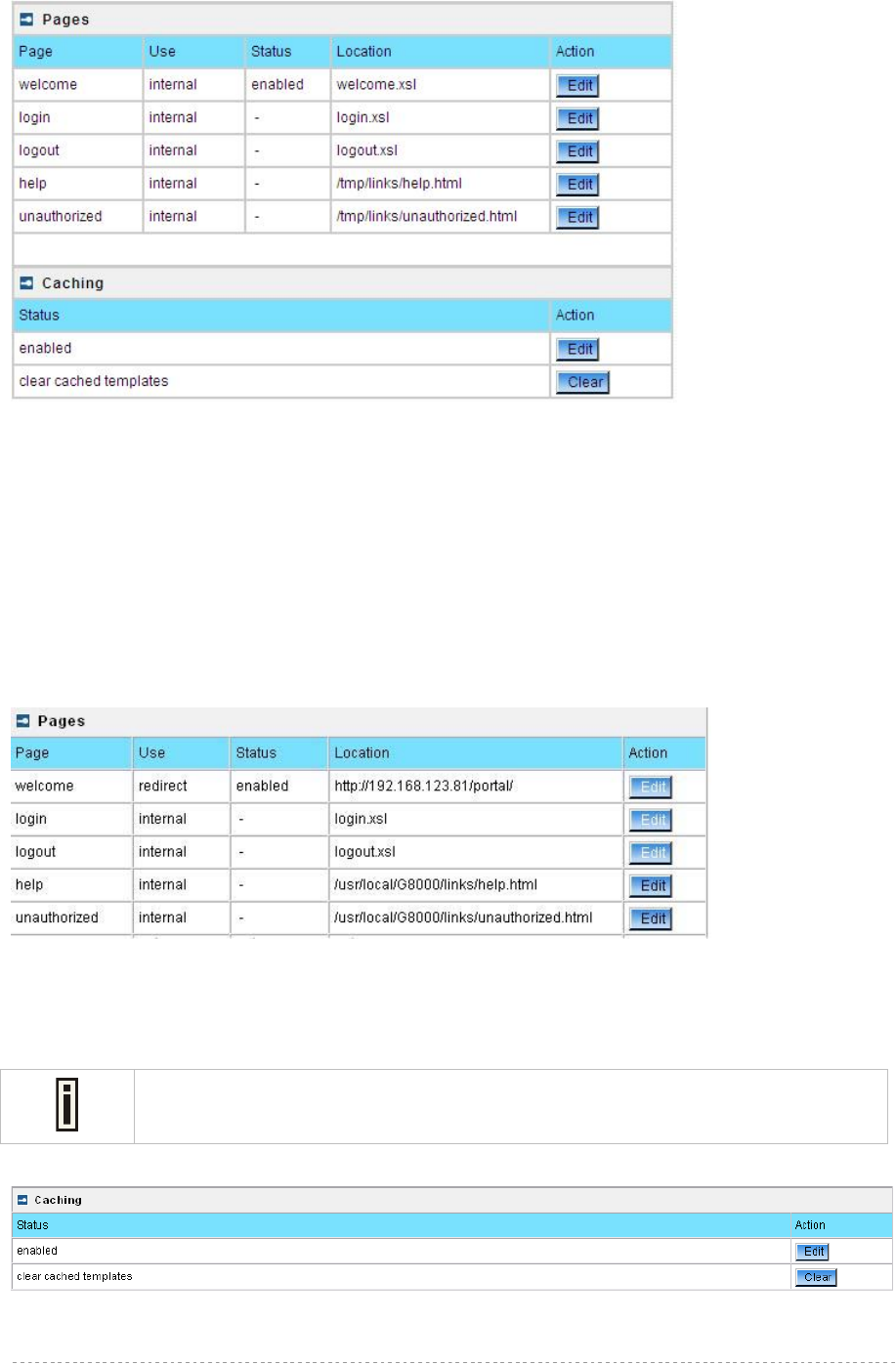
BW1254 User Guide v1.0 Nov. 2013
Page 137 of 184
Figure 239 – Available User Pages for Configuration
Login/Logout/Help/Unauthorized pages settings detailed description is given in the Chapter 5 –
User Pages. Only Welcome page settings reference is provided here.
Welcome – first page the user gets when he/she opens its browser and enters the URL.
Internal – choose this option when using the internal user pages templates.
External – choose this option when uploading your own user pages templates.
Redirect – choose this option when using the Extended UAM function (see Chapter 5 –
User Pages.).
Status – choose enable/disable welcome page status. Note that redirect option with status ‘disabled’
would work.
Location – enter location for external templates or redirect (e.g. WAS IP address).
Figure 240 – Redirect User Pages
Welcome page with redirect option selected redirects the user authentication process to the
specified location. The user welcome/login/logout page can be implemented as simple HTML (not
required to use the .XSL or default user pages templates) in such case.
The redirect location URL should be specified in Walled Garden URL, otherwise the
redirect would NOT WORK.
Figure 241 – Caching Option
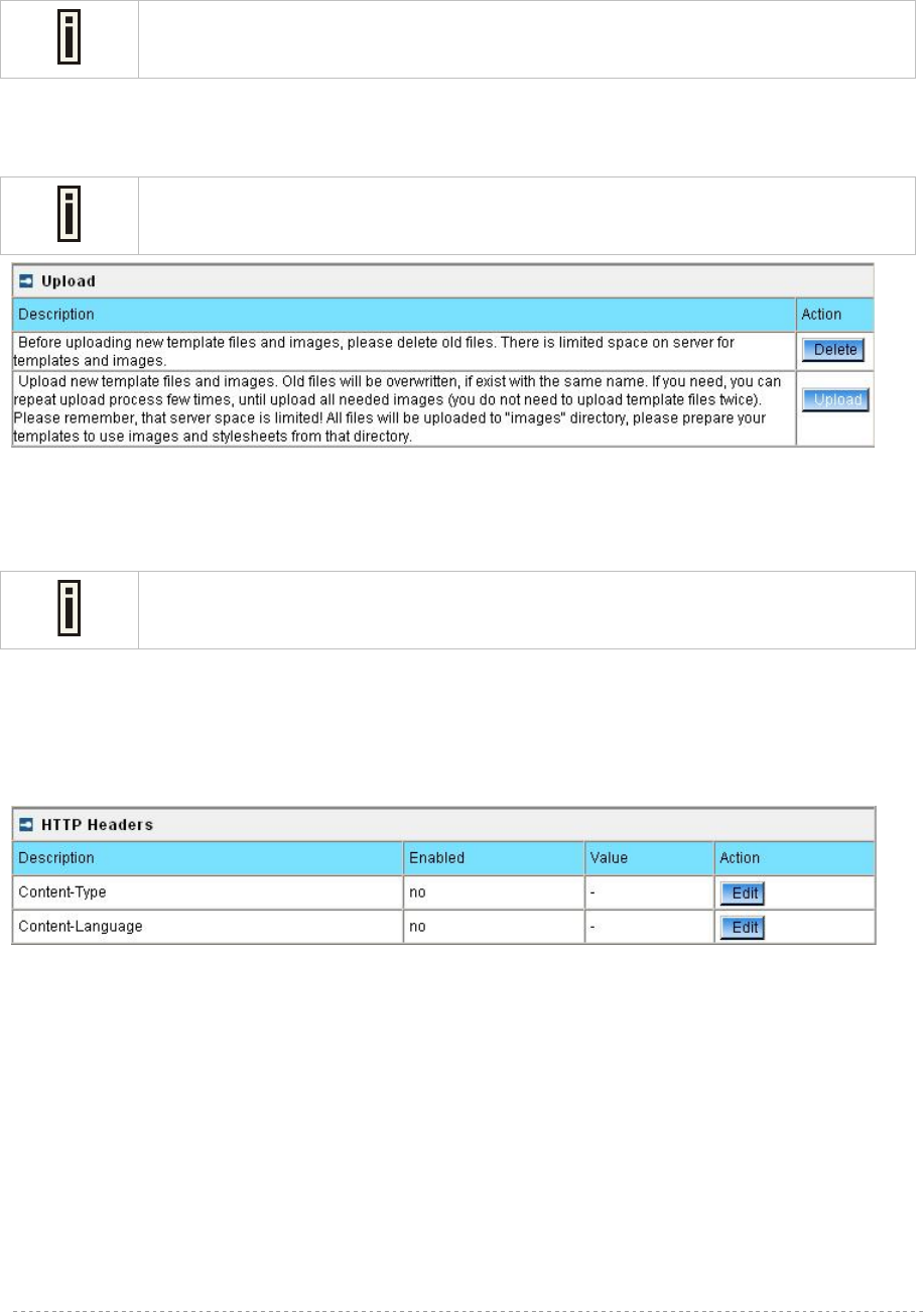
BW1254 User Guide v1.0 Nov. 2013
Page 138 of 184
Caching option can be used for caching the external uploaded user pages (available choice:
enabled/disabled)
Clear – click the button to clear cached user pages.
Controller cache is also cleared after device reboot/reset.
User | Upload
Please contact with BROWAN if you need the user pages template sample.
Figure 242 – Upload Page
Delete – click the button to delete earlier uploaded files from controller memory.
Upload – click the button to select and upload new user pages.
How to upload user pages see in the Chapter 5 – User Pages.
User | HTTP Headers
System administrator can set HTML headers encoding and language settings for BW1254 web
management interface and new uploaded user pages. Select User | HTTP Headers menu:
Figure 243 – HTTP Headers Settings
BW1254 device supports some http META tags. Syntax of such META tags:
<META HTTP-EQUIV="name" CONTENT="content">
Currently BW1254 supports Content-Type and Content-Language tags:
Content-Type is used to define document char set (used, when text has non-Latin letters, like
language letters).
Content-Language may be used to declare the natural language of the document.
BW1254 automatically adds defined content-type and content-language to generated XML. Then user
pages (.XSL) templates will use these parameters to generate the output HTML.
Click the change button to define new headers of the web management interface on user pages
templates. The default HTML encoding is ISO-8859-1, language = English. Enable the HTTP header
status and default values appear:
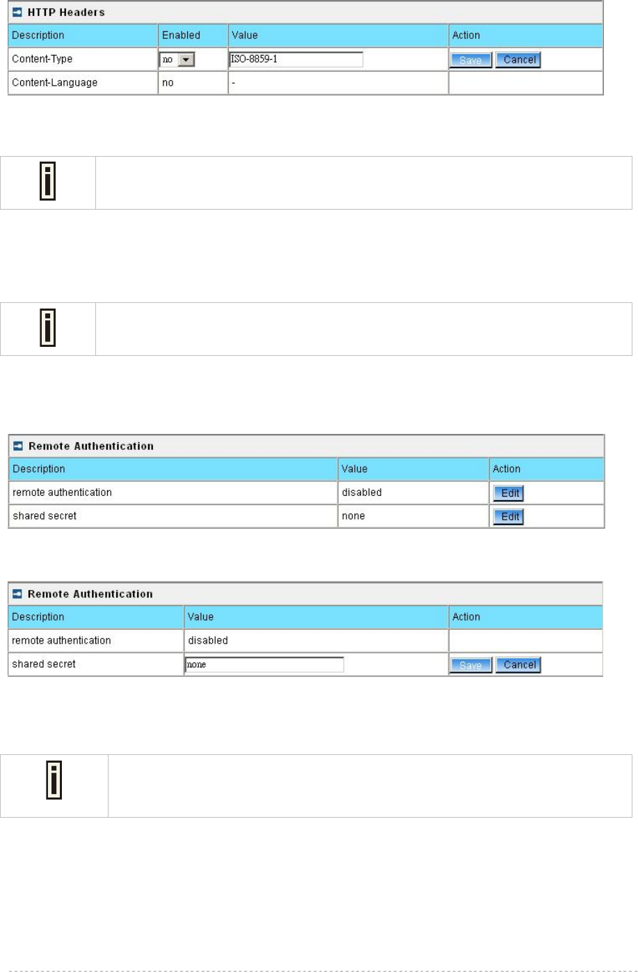
BW1254 User Guide v1.0 Nov. 2013
Page 139 of 184
Figure 244 – Set HTTP Headers
The system administrator can set his own header encoding and language settings.
Use the HTML 4.01 specification to define the header encoding and language.
User | Remote Authentication
Read more about the extended UAM feature in Chapter 5 – User Pages, section:
Extended UAM
The Remote Authentication feature under the User menu allows an external Web Application Server
(WAS) to intercept/take part in the user authentication process, and to log on and log off users
externally. It provides a means to query user session information as well. By default such remote
authentication is disabled:
Figure 245 – Remote Authentication
Click the edit button next to appropriate settings to specify remote authentication parameters:
Figure 246 – Enable Remote Authentication
Remote Authentication – select status: [enabled/disabled].
Shared Secret – enter password for WAS to communicate with AC [sting (4-32), no spaces allowed].
The shared secret must match that configured on the WAS. This shared secret
allows the WAS to initiate a secure (SSL) command session with the BW1254 to
pass login commands.
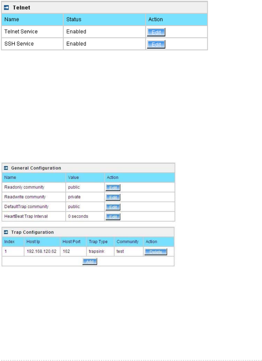
BW1254 User Guide v1.0 Nov. 2013
Page 140 of 184
Services
Services | Telnet
Use Services | Telnet menu to manage the telnet/SSH service of your BW1254.
Figure 247 – System Configuration settings
Telnet Service – Enable or disable telnet service of BW1254
SSH Service – Enable or disable SSH service of BW1254
The default of these two services are all Enabled. The current IETF SSH (SSHv2) is supported for
security of accessing BW1254 via telnet/CLISH.
Services | SNMP
SNMP is the standard protocol that regulates network management over the Internet. To
communicate with SNMP manager you must set up the same SNMP communities and identifiers on
both ends: manager and agent.
Use the Services | SNMP menu to change current SNMP configuration.
Figure 248 – SNMP settings
Readonly community – community name is used in SNMP version 1 and version 2c. Read-only
(public) community allows reading values, but denies any attempt to change values [1-32 all ASCII
printable characters, no spaces]
Readwrite community – community name is used in SNMP version 1 and version 2c. Read-write
(private) community allows to read and (where possible) change values [1-32 all ASCII printable
characters, no spaces]
Default Trap community – the default SNMP community name used for traps without specified
communities. The default community by most systems is "public". The community string must match
the community string used by the SNMP network management system (NMS) [1-32 all ASCII
printable characters, no spaces]
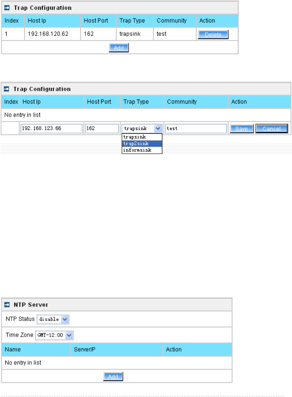
BW1254 User Guide v1.0 Nov. 2013
Page 141 of 184
HeartBeat Trap Interval – define the interval that AP send trap information to the server.[in seconds]
Trap Configuration Table:
You can configure your SNMP agent to send SNMP Traps (and/or inform notifications) under the
defined host (SNMP manager) and community name (optional).
Figure 249 – SNMP Trap table settings
Click Add to add a new SNMP manager or Delete to delete a specific SNMP manager. Clicking Add:
Figure 250 – Add SNMP Trap
Host IP – enter SNMP manager IP address [dots and digits]
Host Port – enter the port number the trap messages should be send through [number]
Trap Type – select trap message type [v1/v2/inform]
Community – specify the community name at a SNMP trap message. This community will be used in
trap messages to authenticate the SNMP manager. If not defined, the default trap community name
will be used (specified in the SNMP table) [1-32 all ASCII printable characters, no spaces]
Save – save all current settings
Cancel – restore the last settings
Services | NTP
NTP (Network Time Protocol) is used to synchronize the system time with the selected network NTP
server. Use the Services | NTP menu to configure the NTP service:
Figure 251 – NTP Settings
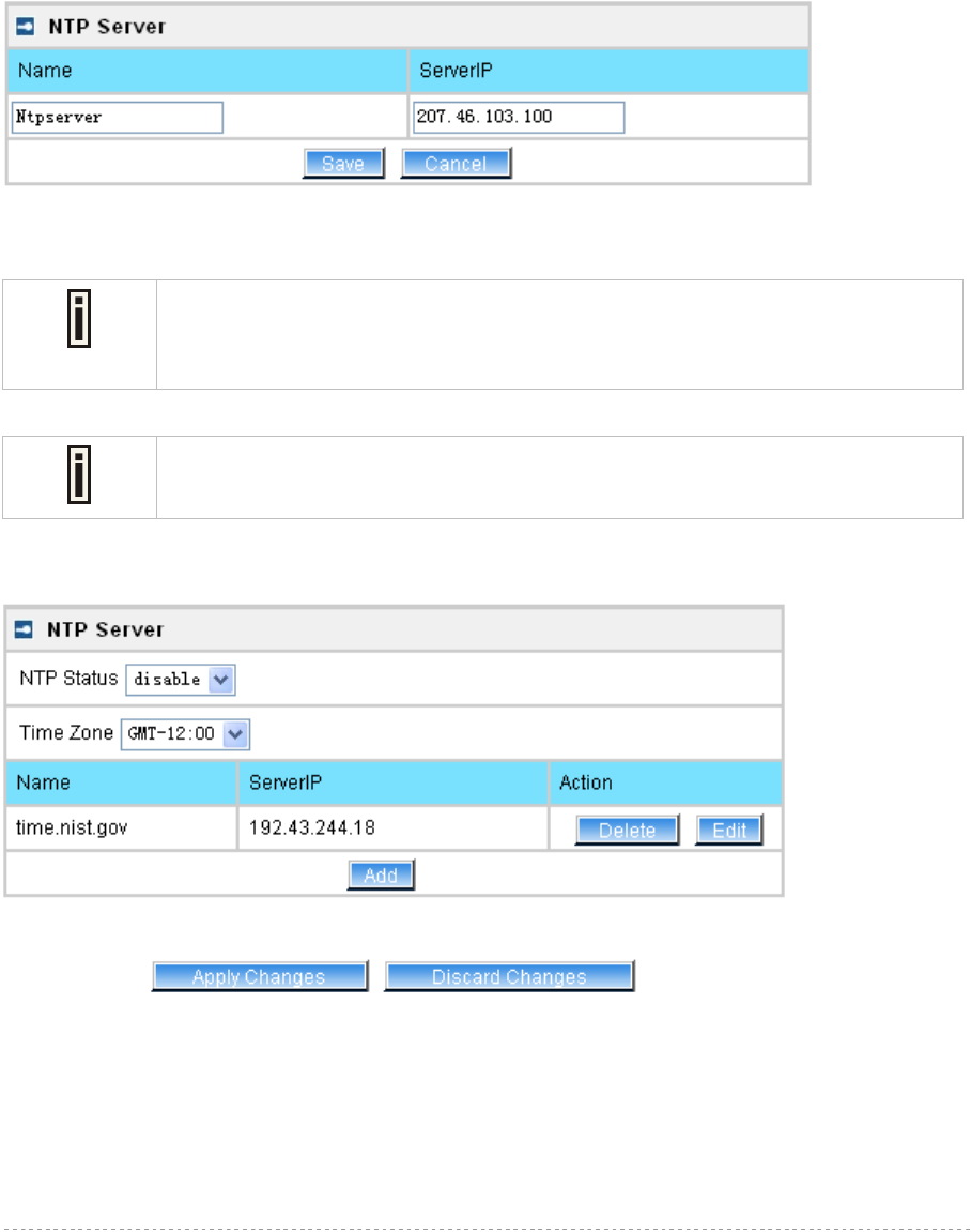
BW1254 User Guide v1.0 Nov. 2013
Page 142 of 184
NTP Status – specify enable or disable this NTP service
Time Zone – specify the time zone for NTP service
Delete – delete the existed NTP server
Edit – edit the settings of the existed NTP server
Add – add a new NTP server setting for synchronizing time
Clicking Add button to add a new NTP server:
Figure 252 – Add new NTP server setting
Two NTP servers can be configured under Services | NTP menu. And only IP
address is accepted for NTP server.
Please enter at least one NTP server when enable NTP service.
The Name of NTP server should be unique.
Change status or leave in the default state if no editing is necessary and click the Save button.
Figure 253 – Save the NTP server Changes
Change the Time Zone for your own local time and change the NTP status to enable or disable.
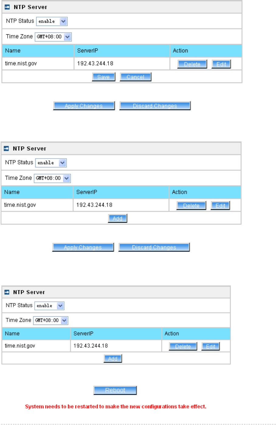
BW1254 User Guide v1.0 Nov. 2013
Page 143 of 184
Figure 254 – Edit Time Zone setting/NTP status
Click Save button to save new Time Zone setting.
Figure 255 – Apply or Discard Time Zone/NTP status Changes
For each change of settings, the BW1254 needs to be restarted to apply all settings changes when
clicking Apply Changes. Request for reboot server appears:
Figure 256 – Reboot information
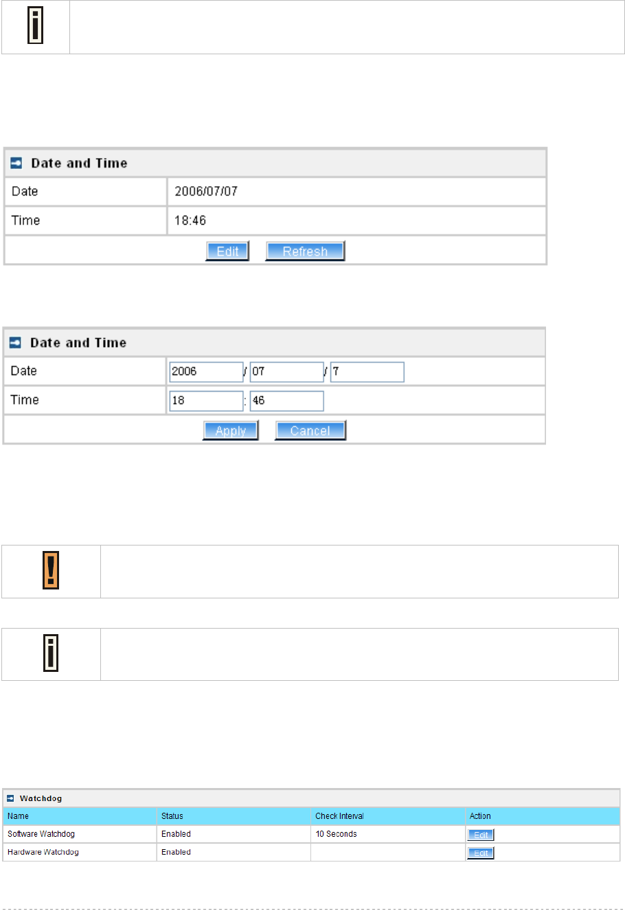
BW1254 User Guide v1.0 Nov. 2013
Page 144 of 184
Reboot – click the button to restart the server and apply the changes
If there is no other settings needed to be modified, click the Reboot button to apply all
changes. If there are any other settings need to be changed, continuously to finish and
apply all changes and then click Reboot button to restart and take effect for all settings.
Services | Time
Configure the system time manually under Services | Time menu.
Figure 257 – Time Settings
Click Edit to change current system time.
Figure 258 – Edit Date and Time Settings
Change the Date and Time or leave in the default value if no editing is necessary and click the Apply
button. Thus the modified time will be taken effect at once. No reboot is needed.
If NTP is enabled, the local time cannot be modified.
Since BW1254 hasn’t RTC (real-time clock), the system time will back to
1970/01/01 00:00 after reboot.
Services | Watchdog
BW1254 supply watchdog function for the reliability. Use Services | Watchdog to enable/disable
watchdog service.
Figure 259 – Watchdog settings
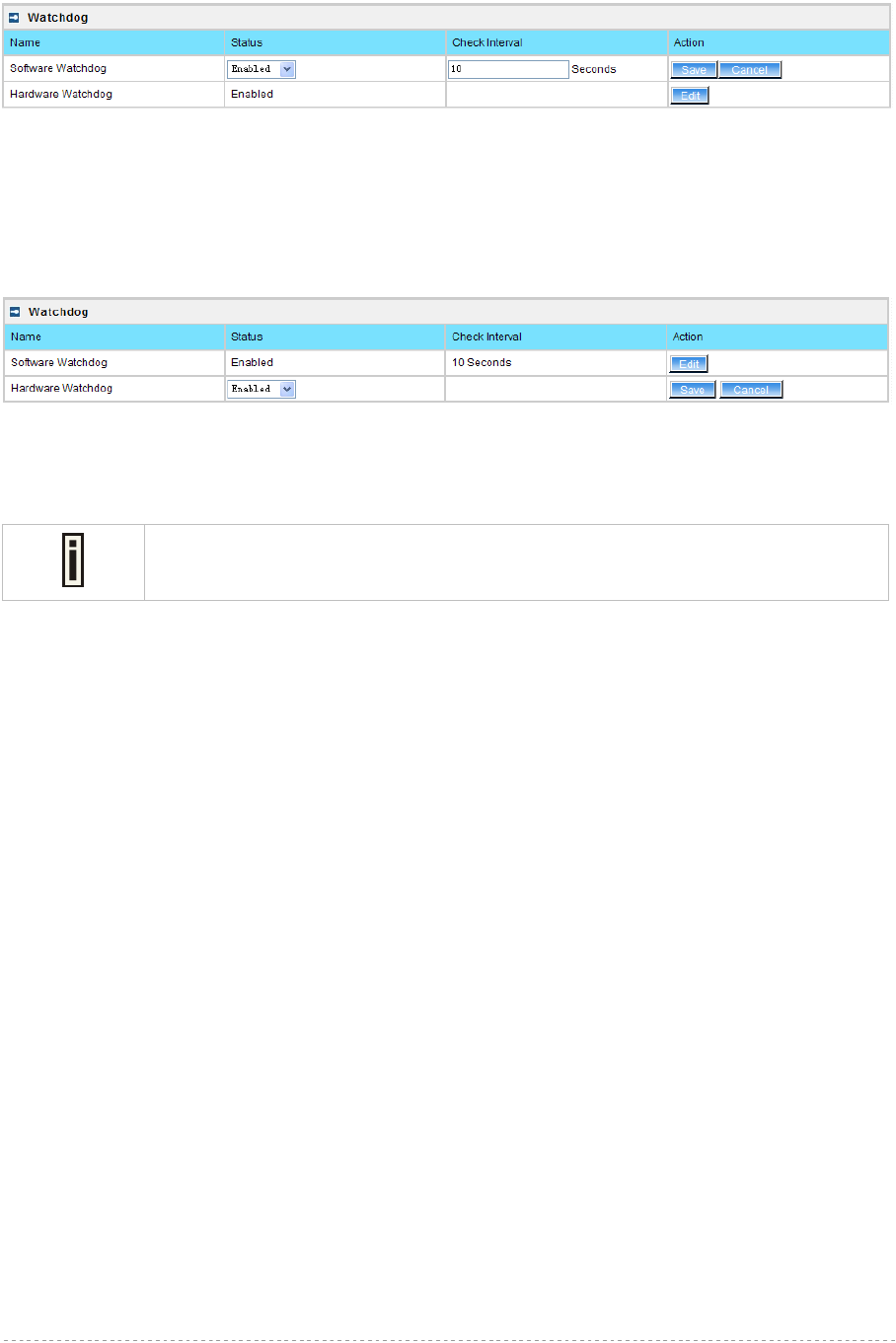
BW1254 User Guide v1.0 Nov. 2013
Page 145 of 184
Click Edit button to edit watchdog settings. The similar UI will be appeared like below:
Figure 260 – edit Software Watchdog settings
Status – Enable or Disable software watchdog
Check Interval – the periodical time that software watchdog checks the whole file system of BW1254.
The hardware watchdog function will protect device even the operation system crash.
Figure 261 – edit hardware watchdog settings
Status – Enable or Disable hardware watchdog
The default value is enabled for both Software Watchdog and Hardware Watchdog.
It is strongly recommended to enable the watchdog function.
Click Save and follow the UI instruction to apply changes and reboot the device for apply all the
modified settings.
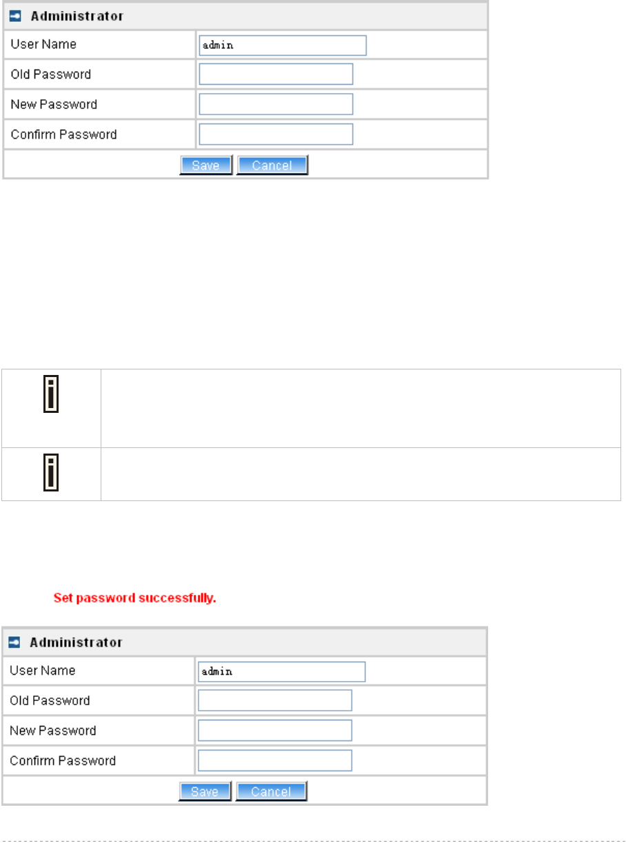
BW1254 User Guide v1.0 Nov. 2013
Page 146 of 184
System
System | Administrator
The System | Administrator menu is for changing the administrator’s settings: username and
password:
Figure 262 – system security settings
User Name – administrator username for access to BW1254 (e.g. web interface, CLI mode) [1-32
symbols, spaces not allowed]
Old Password – old password value
New Password – new password value used for user authentication in the system [4-8 characters,
spaces not allowed]
Confirm Password – re-enter the new password to verify its accuracy
Save – click to save new administrator settings.
Default administrator logon settings are:
User Name: admin
Password: admin01
Password length is from 4 to 8 characters.
After filling in the right Old password and the New Password, clicking the Save button for taking effect
immediately.
After clicking Save button, the below UI will be shown to notify that the new password setting has
been taken place:
Figure 263 – system security settings save and take effect successfully
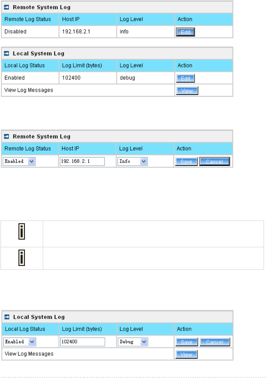
BW1254 User Guide v1.0 Nov. 2013
Page 147 of 184
System | System Log
Use the System | System Log menu to trace your AP system processes and get the system log
locally or on the remote log server.
Figure 264 – System Log settings
To enable the System Log remote sending function, click the Edit button on the Remote System Log
table and choose the enabled option:
Figure 265 – Configure Remote System Log Utility
Remote Log Status – choose disable/enable remote log [enabled/disabled]
Host IP – specify the host IP address where to send the System Log messages [dots and digits]
Log Level – specify the remote log message level you want to trace [critical, error, warning, info and
debug]
Do not output “debug” log unless there are important issue needs to be clarified.
Debug log will output all of the information so that it will severely drop down the
network performance.
BW1254 support standard sys. log server.
Save – save changes
Cancel – restore the previous values
To view the System Log locally, click the Edit button on the Local System Log table and choose the
enabled option:
Figure 266 – Configure Local System Log
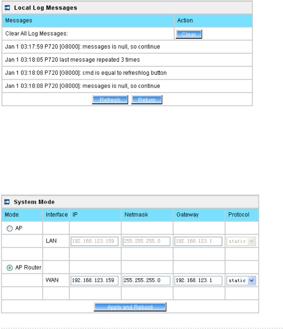
BW1254 User Guide v1.0 Nov. 2013
Page 148 of 184
Local Log Status – choose disable/enable local log [enabled/disabled]
Log Limit – specify the maximum length of local log message in byte [20000-512000]
Log Level – specify the local log message level you want to trace [critical, error, warning, info and
debug]
Save – save changes
Cancel – restore the previous values
View – view the log messages locally
Click View button, a similar screen will appear as below:
Figure 267 – View Local Log Messages
Clear – clear current log message
Refresh – get the updated log messages
Return – back to System Log page
System | System Mode
In this page, you can select the system mode of your BW1254.
Figure 268 – System Mode Settings
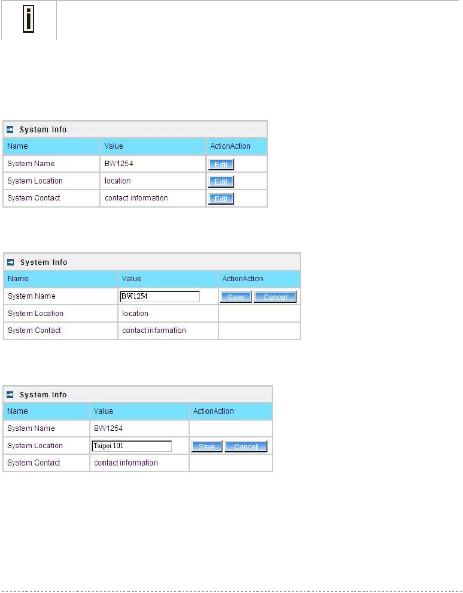
BW1254 User Guide v1.0 Nov. 2013
Page 149 of 184
Mode – select whether the system mode of BW1254 is AP mode or AP Router mode
IP – specify the IP address of current interface [dots and digits]
Netmask – specify the subnet mask of current interface [dots and digits]
Gateway – specify the gateway to other networks
Protocol – specify static for setting IP address manually and dhcp for getting IP address dynamically
acting as DHCP client
Apply and Reboot – click the button to restart the device and apply all setting changes
The Web Interface in AP-Router mode is different from that in AP mode. For the
detailed configuration of BW1254 working in AP mode, please refer to: Chapter 3 –
Reference Manual----AP Mode
System | System Info
Administrator can self-define the device information including the system name, system location and
system contact information of his BW1254.
Figure 269 – System info Settings
System Name –edit the system name, the column length range is 1 to 255.
Figure 270 –edit the system name
System Location – edit the system location, the column length range is 1 to 255.
Figure 271 –edit the system laocation
System Contact – edit the system contact, the column length range is 1 to 255.
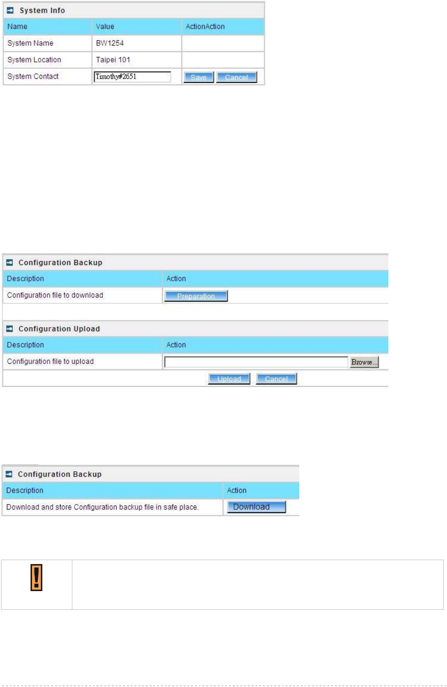
BW1254 User Guide v1.0 Nov. 2013
Page 150 of 184
Figure 272 –edit the system contact information
Save – click the button to save the change.
Cancel – restore all previous values
System | Configuration
Use the System | Configuration menu to download current configuration or restore specified
configuration.
Configuration Backup – download current working system configuration for backup
Configuration Upload – upload system configuration for restore
Figure 273 – System Configuration settings
Click the Preparation button to start saving the configuration file.
Click the Download button to download current working configuration locally.
Figure 274 – Backup settings
By default the device configuration name is cfgbackup.cfg.
A configuration file name will be required when you download/save the
configuration file. And please remember or re-name the file if necessary. The
configuration file name should only include characters or numbers. Otherwise, this
configuration file will not upload to BW1254.
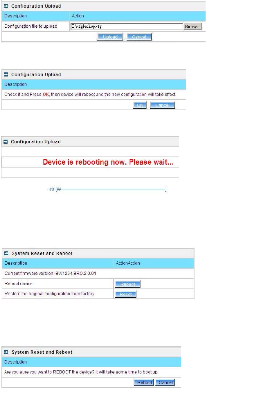
BW1254 User Guide v1.0 Nov. 2013
Page 151 of 184
You can upload saved configuration file any time you want to restore this configuration to the device
by using the Browse button. Select the configuration file and upload it on the device:
Figure 275 – Configuration Upload/Restore - 1
Click Upload for upload the specified configuration and then the similar UI appears
Figure 276 – Configuration Upload/Restore - 2
Click OK button to restore and AP will reboot immediately to take effect.
Figure 277 – Configuration Upload/Restore - 3
System | Reset and Reboot
Use this function to reboot device or restore to factory default.
Figure 278 – System Reset setting
Reboot – reboot the device
Reset – reset System to Factory Defaults
To reboot the device, click Reboot and then the below appears to make sure:
Figure 279 – Reboot the device

BW1254 User Guide v1.0 Nov. 2013
Page 152 of 184
To reset the device, click Reset and then the below appears to make sure:
Figure 280 – Reset the device
Click reset button the device will reset and reboot immediately to take effect.
Please note that all settings including the administrator settings will be set back to
the factory default when Reset is implement.
System | Local Upgrade
Upload – Update your device firmware locally.
Figure 281 – Firmware Upgrade
Click the Upload and then click the browse button to specify the full path of the new firmware image
and click the Upload button:
Figure 282 – Firmware Upgrade
Click the Upgrade button to flash and upgrade the firmware.
Please make sure the firmware is correct for BW1254. Otherwise the upgrade will
be failed.
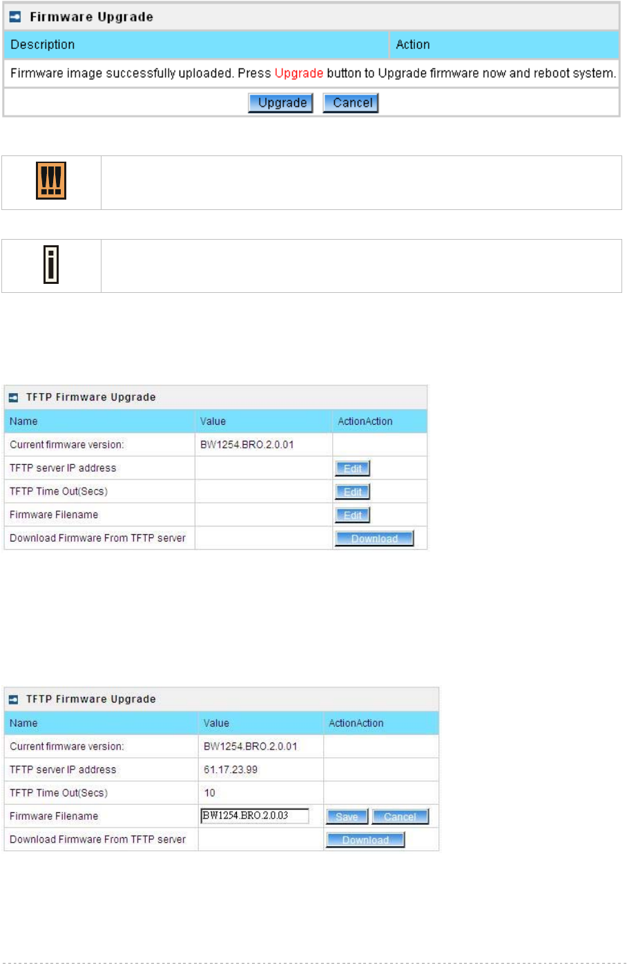
BW1254 User Guide v1.0 Nov. 2013
Page 153 of 184
Figure 283 – upgrade firmware
Do not turn off the BW1254 during the firmware update process.
It will backward to previous version in case upgrade failure.
Update firmware will take about 4 minutes.
System | TFTP Upgrade
BW1254 support firmware upgrade via TFTP server.
Figure 284 – TFTP Firmware Upgrade
Current firmware version – Show the current firmware version.
TFTP server IP address - Specify the IP address of TFTP server which firmware located.
TFTP Time Out(Secs) – Specify the TFTP server communication time out in second.
Firmware Filename – Specify the upgrade firmware name to be download.
Figure 285 – TFTP Firmware Upgrade setting
Click “Edit” button to specify the TFTP server IP address,time out interval and firmware filename and
save the configuration then press “Download” button to download the firmware.
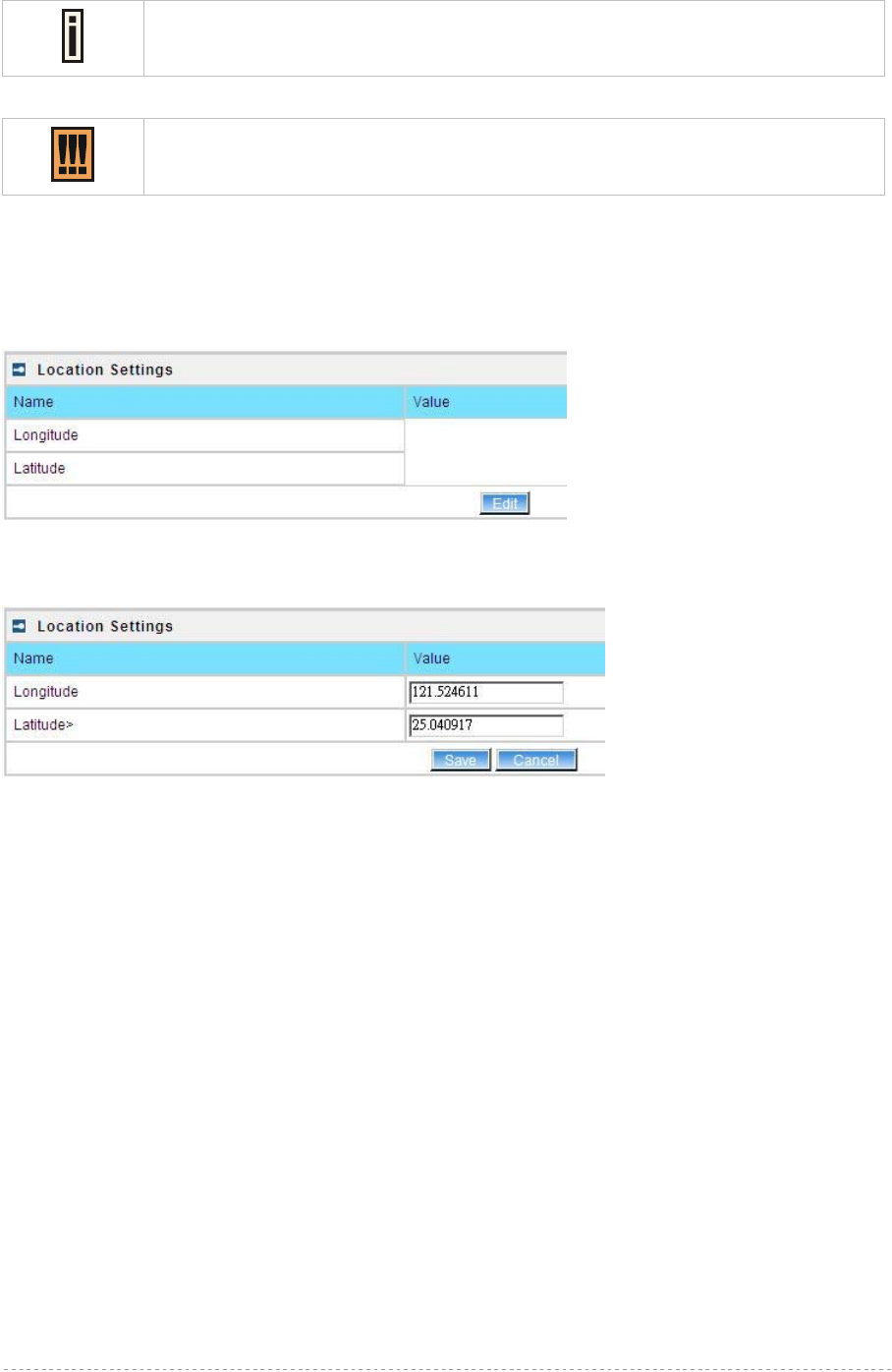
BW1254 User Guide v1.0 Nov. 2013
Page 154 of 184
Please make sure the firmware is correct for BW1254. Otherwise the upgrade will
be failed.
Do not turn off the BW1254 during the firmware update process.
It will backward to previous version in case upgrade failure.
System | Location Settings
You can define the longitude and latitude for the device information or for the NMS to locate the
device location.
Figure 286 – location setting
Click edit to enter the Longitude and Latitude in digit and dot format.
Figure 287 – edit location[longitude/latitude]
Click save button to save it.
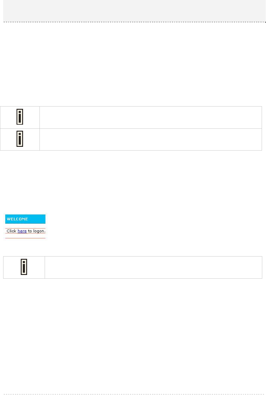
BW1254 User Guide v1.0 Nov. 2013
Page 155 of 184
This chapter describes the user pages based on XSL format. Detailed instructions on how to change
and upload new user pages are given below.
When launching his/her web browser the user's initial HTTP request will be redirected to an operator
defined set of web pages, further called the "user pages". User pages are:
Welcome page– the first page presented to the user.
Login page– subscriber authentication page, allows the user to login to the network.
Logout page– small pop-up window for logged-on user statistics and log-out function.
Help page – get help with the login process.
Unauthorized page – this page is displayed when web login or EAP login methods are disabled
on the BW1254 for subscribers.
The following mentioned user pages are factory default. The operator/owner can
upload new templates for all user pages based on their designed.
Contact with BROWAN if you need the User Pages templates samples.
User Pages Overview
Welcome Page
Welcome page is the first page a subscriber receives when he starts his web browser and enters any
URL. By default it’s a very simple page and provides only a link to the login page.
Figure 288 – Welcome Page
The operator/owner can change the welcome page according to their designed.
See more details in section: Changing User Pages.
Login Page
The subscriber gets to the login page after clicking the link on the welcome page. The login page is
loaded from the BW1254. To get access to the network, the user should enter his authentication
settings: login name and password and click the login button:
Chapter 5 – User Pages (Based on XSL)
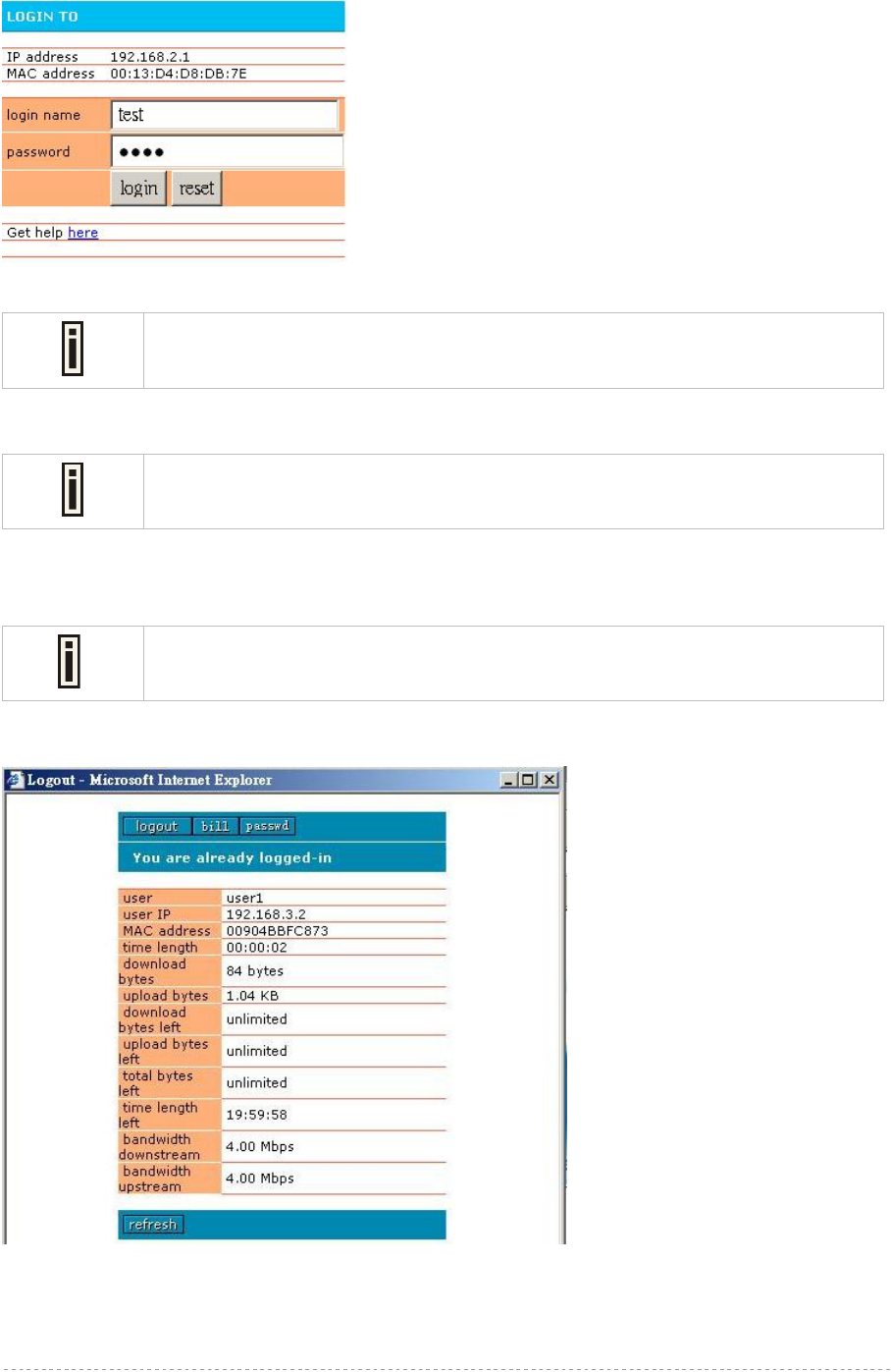
BW1254 User Guide v1.0 Nov. 2013
Page 156 of 184
Figure 289 – Simple Login Page
The login name and password can be obtained from your Hotspot Operator.
The login page also displays subscriber’s logical and physical network addresses (IP and MAC).
Once authenticated, a start page appears. In addition, a smaller logout window (page) pops up.
The operator/owner can change the login page according to its needs. See more
details in section: Changing User Pages.
Logout Page
Make sure the JavaScript is enabled on your Web browser; otherwise you will not
receive the logout page.
The Logout page contains the detailed subscriber’s session information and provides function for
logging out of the network:
Figure 290 – Logout Page
Detailed subscriber’s session information includes:
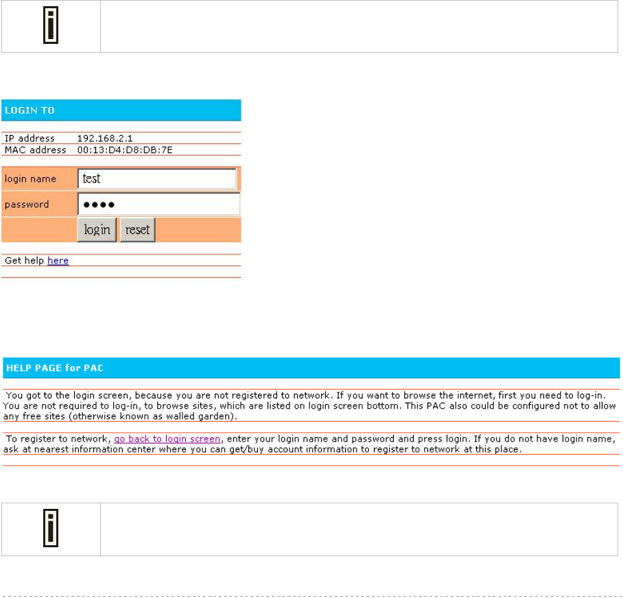
BW1254 User Guide v1.0 Nov. 2013
Page 157 of 184
Logout button – click the button to logout from the network. The log-out pop-up window closes.
Bill button – display subscriber’s billing information (not include current session).
Passwd button – click the button to change subscriber’s password.
User – subscriber’s login name.
User IP – subscriber’s logical network name (IP address).
MAC Address – subscriber’s physical network address.
time length– subscriber’s time length from client log on in format: [hours: minutes: seconds].
Download/upload bytes – subscriber’s session download and upload statistics in bytes.
Download/upload bytes left – session download and upload bytes left for subscriber limited from
RADIUS [in B, KB, MB, GB and unlimited].
Total bytes left – session total (download and upload) bytes left for subscriber limited form RADIUS
[in B, KB, MB, GB and unlimited].
time length left – time length left in format: [hours: minutes: seconds].
Bandwidth downstream/upstream – available upstream and downstream bandwidth for subscriber
limited from RADIUS [in bps].
Refresh button – click the button to refresh the subscriber session information.
The operator/owner can change the logout page interface according to its needs.
See more details in section: Changing User Pages.. All session details are further
accessible via the operator XML interface.
Help Page
Figure 291 – Get help page
Click on the get help link in the login page for help tips related to network registration. A page
appears similar to the following:
Figure 292 – Get help page
The operator/owner can change the help page according to its needs. See more
details in section: Changing User Pages.
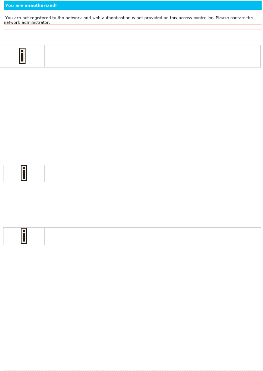
BW1254 User Guide v1.0 Nov. 2013
Page 158 of 184
Unauthorized Page
If web log-on method (UAM) or EAP-based authentication methods are disabled on the AC and the
subscriber attempts to login to the network, he will receive the following page:
Figure 293 – Get help page
The operator/owner can change the unauthorized page according to its needs.
See more details in section: Changing User Pages.
Changing User Pages
As the operator/owner you can modify the user pages freely according to your personal needs and
preferences. User Page templates can be either stored locally on the AC or on an external web server.
Use the user interface | configuration menu to modify user pages. There are two ways to change
and store new user page templates:
External – linking new user page templates from an external server.
Internal – upload new templates to local memory.
Supported user pages template formats:
XSL (Extensible Style sheet Language) for welcome/login/logout/one click pages.
HTML (Hypertext Markup Language for help/unauthorized pages.
The welcome, Login and logout pages must be in .XSL format.
The following image formats are supported for new templates. Other formats are not accepted:
PNG
GIF
JPG
The following examples demonstrate the use of internal and external user pages.
Contact with BROWAN if you need the User Pages templates samples.
Example for External Pages
Step 1 Prepare your new user pages template for each user page:
welcome/login/logout/help/unauthorized.
Step 2 Under the user interface | configuration | pages menu select the user page you
want to change (e.g. login)
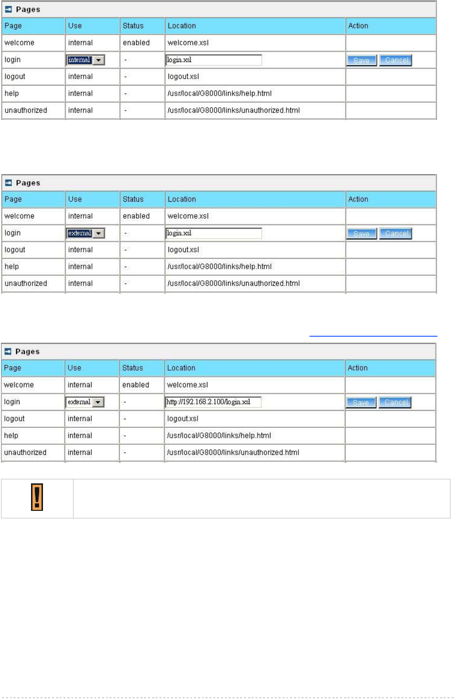
BW1254 User Guide v1.0 Nov. 2013
Page 159 of 184
Figure 294 - configure external pages
Step 3 Choose the external option under the use column:
Figure 295 - configure external pages
Step 4 Specify the new user page location in the location field (http://servername/filelocation):
Figure 296 - configure external pages
Do not to upload different type of formats. It will not be displayed properly.
Step 5 Save entered changes with the apply changes button:
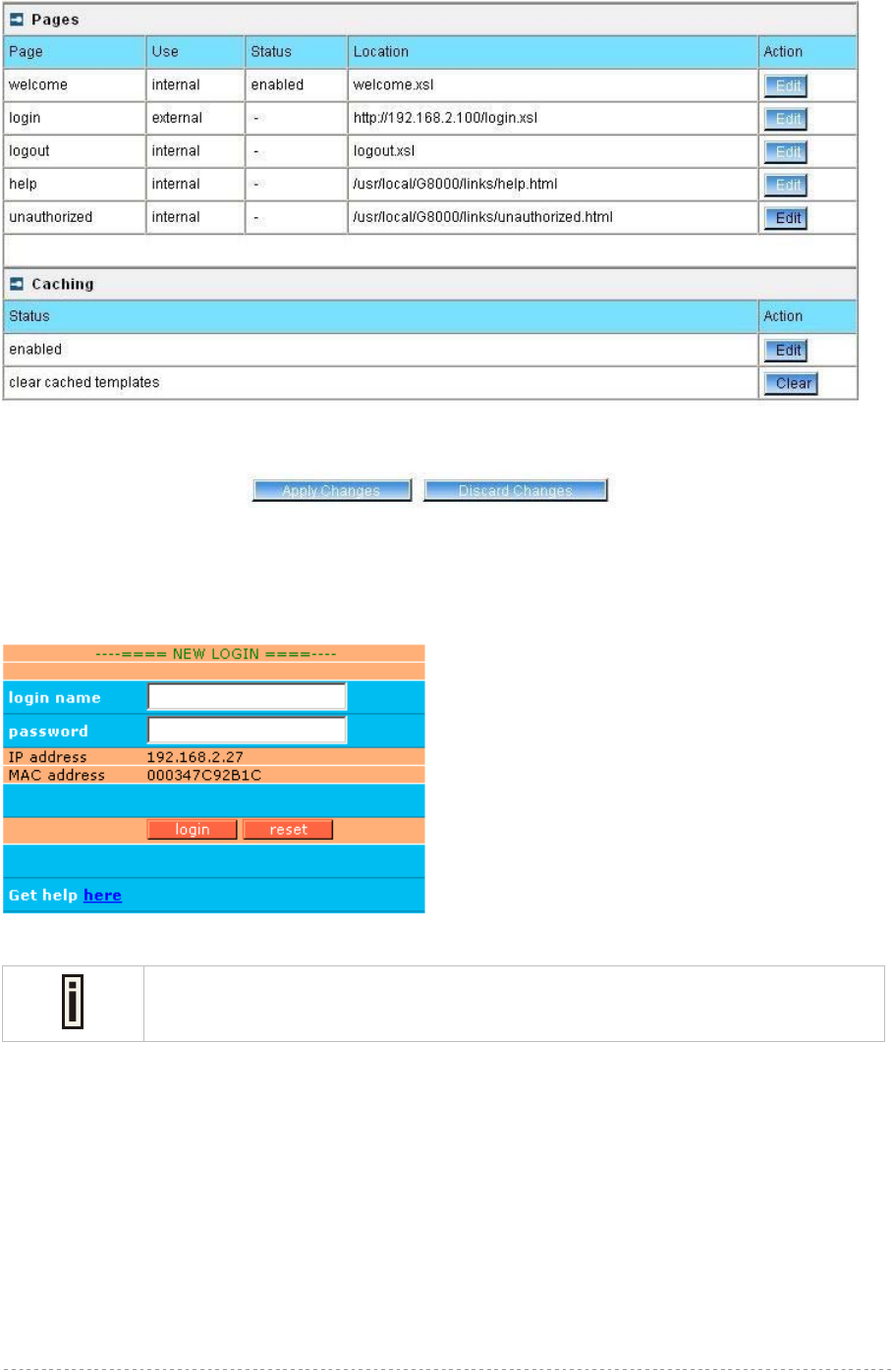
BW1254 User Guide v1.0 Nov. 2013
Page 160 of 184
Figure 297 - configure external pages
Step 6 Check for new uploaded user page (e.g. login):
Figure 298 - login page
If at anytime you wish to restore factory default user pages, click the reset button
under the system | reset & reboot menu.
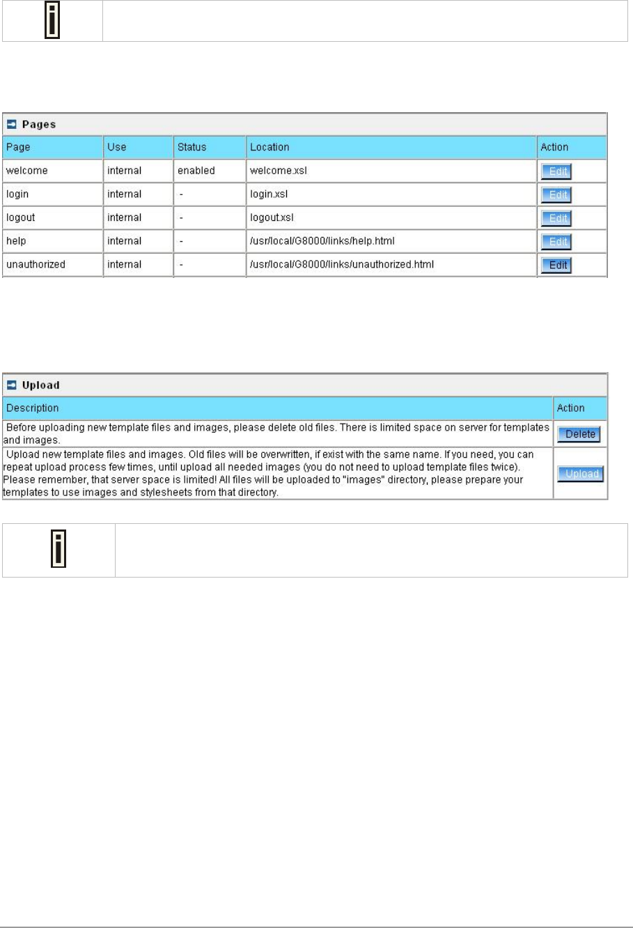
BW1254 User Guide Sep. 2013
Example for Internal Pages
We will use the user pages templates to show the example how to upload the internal pages. Follow
the steps below:
Contact with BROWAN if you need the User Pages templates samples.
Step 1 Ensure that internal option is selected for all user pages you want to change. By
default internal option is defined for all pages:
Figure 299 - internal pages
Step 2 Under the user | upload menu click the upload button to upload new prepared
user pages:
Figure 300 - upload page
The memory space in the AP for internal user pages is limited to 1 MB.
Step 3 Specify the location of new user page templates by clicking the browse button or
enter the location manually.
Specify the location for the additional files of new user page templates: images and
a cascading style sheet file (css) by clicking the browse button or enter the
location manually:
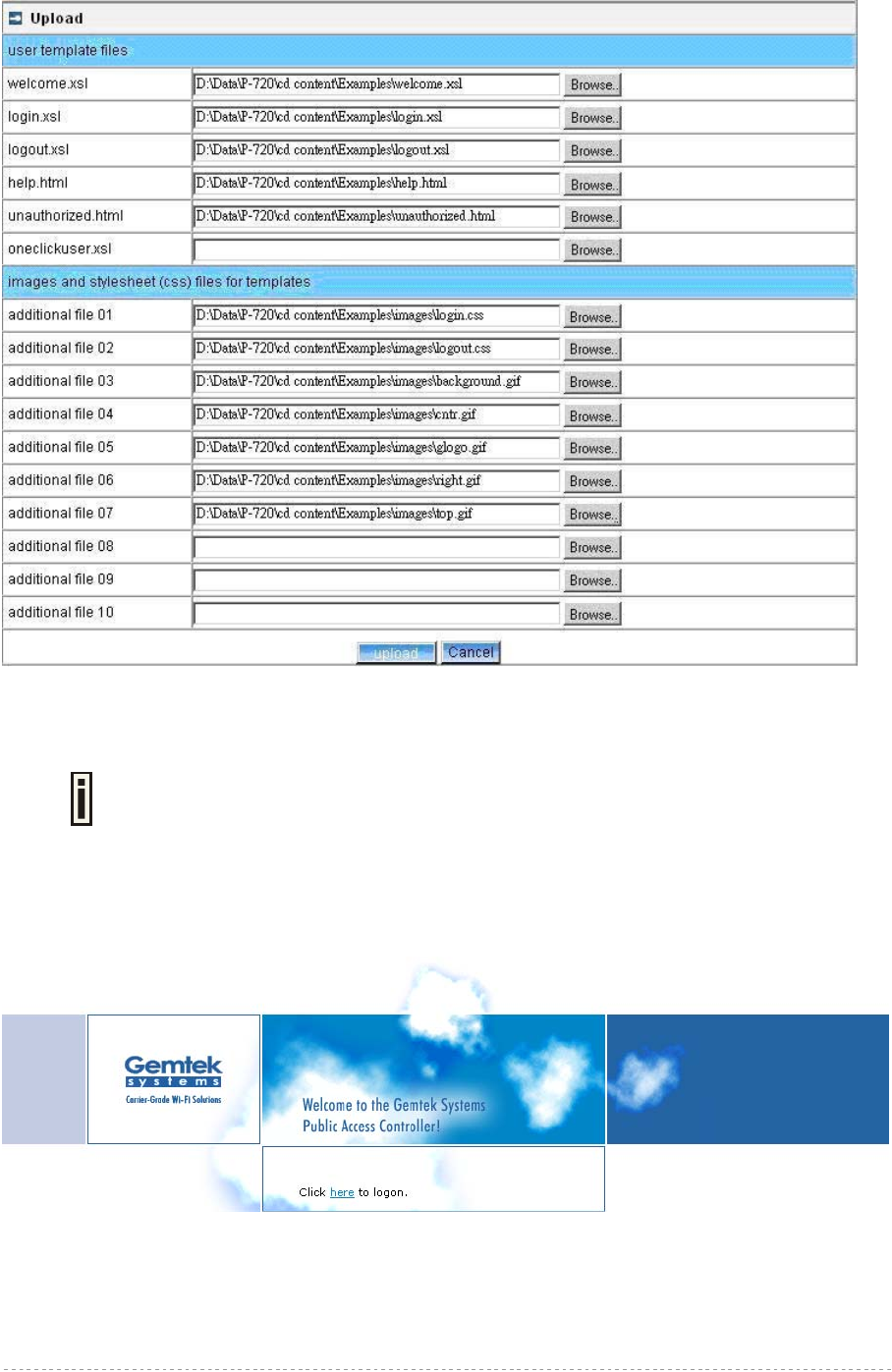
BW1254 User Guide v1.0 Nov. 2013
Page 162 of 184
Figure 301 - upload template files
Step 4 Click the upload button to upload specified templates and files.
You do not need to upload all additional files at once. You can repeat the upload
process a number of times until all necessary images are uploaded.
Step 5 Check for the newly uploaded user pages and images to ensure that everything is
uploaded and displayed correctly. Go to the link:
https://<device-IP-address>/ to get to the new user welcome page:
Figure 302 - customize welcome page
Click the here link or enter the link directly:
https://<device-IP-address>/login.user to get to the new user login page:

BW1254 User Guide v1.0 Nov. 2013
Page 163 of 184
Figure 303 - customize login page
If at anytime you wish to restore the factory default user pages, click the reset
button under the system | reset & reboot menu.
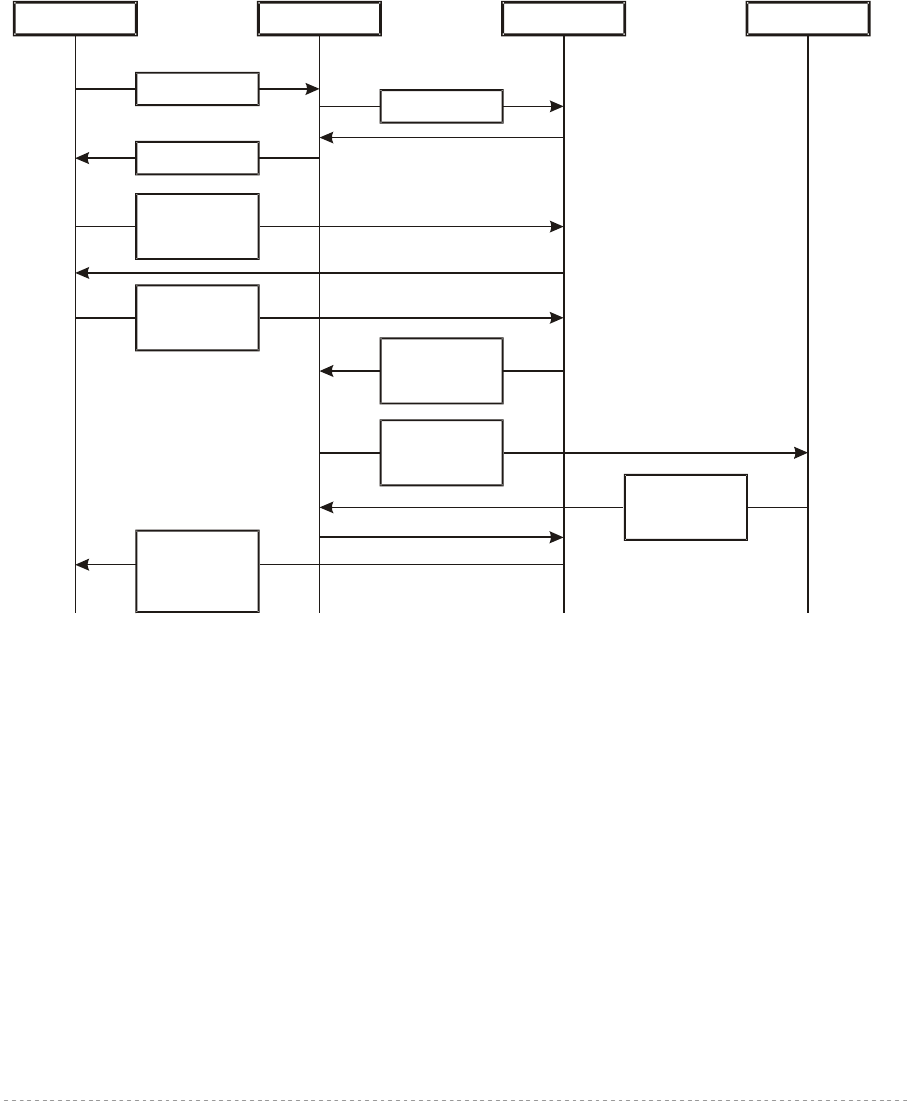
BW1254 User Guide v1.0 Nov. 2013
Page 164 of 184
Extended UAM
The Extensions feature (User menu) allows an external Web Application Server (WAS) to
intercept/take part in the user authentication process externally log on and log off the user as
necessary. It provides means to query user session information as well.
See the following schemes to understand how the remote client authentication works.
Scheme 1:
The remote authentication method when client’s authentication request is re-directed to the external
server (WAS):
Client AC WAS RADIUS Server
1. Initial Request
3. Renders HTML
4. Direct client
communication
with WAS
5. Client sends
his/her login and
password
9. WAS reports
client status:
authenticated or
not
2. Fetch XSL
6. WAS tries to
authenticate
client
7. AC sends
request to
RADIUS
8. RADIUS reply
authenticated or
not
Figure 304 – Client Remote Authentication Scheme (1)
The Client initiates (1) authentication process. AC intercepts any access to the Internet via HTTP and
redirects the client to the welcome, or login URL on AC. In order to render the custom login screen
HTML page, the AC must be configured to (2) fetch .XSL script from a remote server, which in this
case is a Web Application Server (WAS), or have custom .XSL uploaded on the AC. There is the
ability to enable caching of .XSL scripts (see: User | Pages), thus avoiding fetching of the same
document every time a client requests authentication.
The AC (3) uses .XSL script to render HTML output, which is done by feeding a XML document to a
parsed and prepared for rendering .XSL script. The latter XML document contains all needed
information for Web Application Server like user name, password (if one was entered), user IP
address, MAC address and NAS-Id. Custom .XSL script must generate initial welcome/login screen
so that it embeds all the needed information in a HTML FORM element as hidden elements and
POST data not back to the AC, but to the Web Application Server (5). Thereafter the client
communicates directly with the Web Application Server.
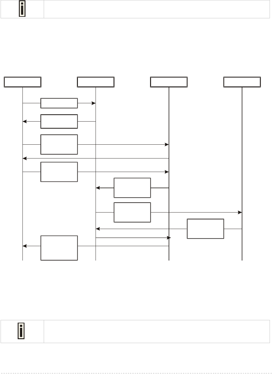
BW1254 User Guide v1.0 Nov. 2013
Page 165 of 184
When the Web Application server has all needed data from the client, it must try to authenticate (6)
the client. Authentication is done by the RADIUS server but through the AC. At this step the shared
secret is used to make the connection between the WAS and the AC. The AC re-sends the
authentication request to the RADIUS server (7). Depending on the status, appropriate authentication
status must be returned back to the WAS but through the AC (8). In step (9), the Web Application
Server knows the client authentication status and reports success or failure back to the client.
The Web Application Server (WAS) must be configured as a free site in the Walled
Garden area.
There is an ability to skip the rendering initial user pages from the .XSL. See the following scheme
when the user initial request is redirected to the specified location.
Scheme 2:
The remote authentication method when client with proxy authentication request is re-directed to the
external server (WAS):
Client AC WAS RADIUS Server
1. Initial Request
2. Replay with
HTTP redirect
3. Direct client
communication
with WAS
4. Client sends
his/her login and
password
8. WAS reports
client status:
authenticated or
not
5. WAS tries to
authenticate
client
6. AC sends
request to
RADIUS
7. RADIUS replay
authenticated or
not
Figure 305 – Client Remote Authentication Scheme (2)
The initial client request (1) can be redirected to the specified location, as redirection URL on the
Web Application server. In such case the client who wants to authenticate gets the redirection from
AC (2). In other words the AC intercepts any access to the Internet via HTTP and redirects the client
to the defined welcome, or login URL on WAS (also see: User | Pages). The further actions are the
same as described in the Scheme 1 (Figure 304 – Client Remote Authentication Scheme (1)).
The WAS location URL under welcome page redirect must be configured as a free
site in the Walled Garden area.
To define such redirection URL use the user | pages menu. Enable welcome page, set the redirect
setting and specify the redirect location for such authentication process (also see: User | Pages).

BW1254 User Guide v1.0 Nov. 2013
Page 166 of 184
Parameters Sent to WAS
Parameters that are send to the external server (WAS) using the remote user authentication method
(UAM).
Parameter Description Comments
nasid NAS server ID value Can be specified under the
Network | RADIUS Properties
menu
nasip WAN IP address for WAS Can be changed or specified
under the Network | Interface
menu.
clientip Client IP address Cannot be defined manually.
mac Client MAC address Cannot be defined manually.
ourl Initial URL where not authorized client enter to
his/her browser and tries to browse. After
authentication the client is redirected in this URL
Optional.
sslport HTTPS port number of AC (by default: 443). Not configurable.
lang Parameter "accept-language" from client browser
request Optional.
Lanip The IP address of the LAN interface the user is
connected to. Can be changed or specified
under the Network | Interface
menu.
In order to logon, log-off or get user status WAS submits POST request to the following URLs:
1. Remote user logon
Script name: pplogon.user
Parameters:
secret shared secret, to protect page from accidental use
ip IP address of user to be logged on.
Username Username of the user to be logged on.
password Password of the user to be logged on.
All parameters are required.
Script call example:
https://P720/pplogon.user?secret=sharedSecret&ip=<user_IP_address>&username
=userName&password=UserPassword
Script produces XML output:
<logon>
<status>Ok</status>
<error>0</error>
<description>User logged on.</description>
<replymessage>Hello user!</replymessage>
</logon>
Response status and error codes:
status error description
OK 0 User is logged on.
Not checked 100 Logon information not checked.
No IP 101 No user IP address supplied.
No username 102 No username supplied.

BW1254 User Guide v1.0 Nov. 2013
Page 167 of 184
Disabled 103 Remote authentication is disabled.
Bad secret 104 Incorrect shared secret supplied.
No password 105 No user password.
OK 110 User already logged on.
Failed to authorize 111 Failed to authorize user.
Bad password 112 Incorrect username or/and password.
Network failed 113 Network connection failed.
Accounting error 114 Accounting error.
Too many users 115 Too many users connected.
Unknown authorization error 120 Unknown authorization error.
<replymessage> is RADIUS Reply-Message attribute value. If RADIUS responds with Reply-
Message(s), they are added to logon response. If RADIUS does not responds with Reply-Message,
<replymessage> attribute is not added to output XML.
2. Remote user log-off
Script name: pplogoff.user
Parameters:
secret shared secret, to protect page from accidental use
ip IP address of user to be logged off.
username Username of the user to be logged off.
mac AC address of the user to be logged off.
All parameters are required, except the IP and MAC. At least one of IP and MAC addresses should be
supplied. If supplied only IP, user is checked and logged off by username and IP. If IP and MAC
addresses are supplied, then user is checked and logged off by username, IP and MAC addresses.
Script call example:
https://P720/pplogoff.user?secret=sharedSecret&username=UserName&ip=<user_I
P_address>
Script produces XML output:
<logoff>
<status>Ok</status>
<error>0</error>
<description>User logged off.</description>
</logoff>
Response statuses and error codes:
status error Description
OK 0 User is logged off.
Not checked 100 Logoff information not checked.
No username 102 No username supplied.
Disabled 103 Remote authentication is disabled.
Bad secret 104 Incorrect shared secret supplied.
No IP/MAC 106 No user IP and/or MAC address
supplied.
No user by MAC 121 User with supplied MAC address not

BW1254 User Guide v1.0 Nov. 2013
Page 168 of 184
found.
No user by IP 122 User with supplied IP address and
username not found.
No user by IP and MAC 123 User with supplied IP, MAC
addresses and username not found.
Failed to logoff 131 Failed to logoff user.
Cannot resolve IP 132 Cannot resolve user IP.
Unknown logoff error 140 Unknown logoff error.
3. Remote user status
Script name: ppstatus.user
Parameters:
secret shared secret, to protect page from accidental use
ip IP address of user to get status.
username Username of the user to get status.
All parameters are required.
Script call example:
https://P720/ppstatus.user?secret=sharedSecret&username=UserName&ip=<user_I
P_address>
Script produces XML output:
XML output, when some error occurs:
<ppstatus>
<status>No user by IP</status>
<error>122</error>
<description>User with supplied IP address not found.</description>
</ppstatus>
Response statuses and error codes:
status error description
OK 0 User status is ok.
Not checked 100 Status information not checked.
No IP 101 No user IP address supplied.
No username 102 No username supplied.
Disabled 103 Remote authentication is disabled.
Bad secret 104 Incorrect shared secret supplied
No user by IP 122 User with supplied IP address not
found.
No user by IP and username 141 User with supplied IP address and
username not found.
XML output when no errors and user statistics got successfully:
<ppstatus>
<status>Ok</status>
<error>0</error>
<description>Got user status.</description>

BW1254 User Guide v1.0 Nov. 2013
Page 169 of 184
<entry id="1">g17</entry>
<entry id="2">192.168.2.117</entry>
<entry id="3">200347C92B63</entry>
<entry id="4">00:00:05</entry>
<entry id="5">3E64C7967A36</entry>
<entry id="6">00:01:10</entry>
<entry id="7">0 bytes</entry>
<entry id="8">0 bytes</entry>
<entry id="9">testlab</entry>
<entry id="10">unlimited</entry>
<entry id="11">unlimited</entry>
<entry id="12">unlimited</entry>
<entry id="13">32 Mbps</entry>
<entry id="14">32 Mbps</entry>
<entry id="15">04:59:55</entry>
<entry id="16">EAP</entry>
</ppstatus>
Status detailed information by ID:
id description
1 User name
2 User IP address
3 User MAC address
4 Session time
5 Session ID
6 User idle time
7 Output bytes
8 Input bytes
9 User WISP name
10 Remaining bytes
11 Remaining output bytes
12 Remaining input bytes
13 Bandwidth upstream
14 Bandwidth downstream
15 Remaining session time
16 Authentication method
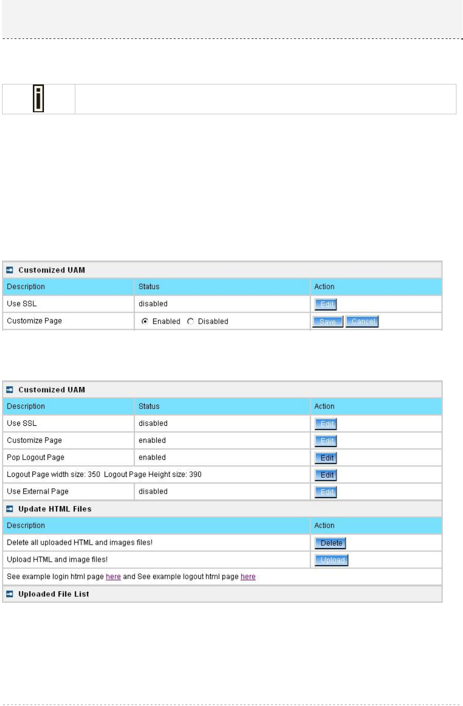
BW1254 User Guide v1.0 Nov. 2013
Page 170 of 184
This chapter assist you on configuring BW1254 customized login/logout pages using the BROWAN
sample templates. There are coffee bar and general samples. User can also create a personalized
login/logout pages based on the provided sample templates.
Contact with BROWAN if you need the templates samples.
Set up your customized user page
Step1. Configure and Upload Customized Login/Logout Page files
Login BW1254 as super administrator and go to User | Customized UAM.
In order to configure BW1254 using the customized login/logout page, Customize Page status must
be set to enable.
To enable Customized Page, edit the Customize page status(User | Customized UAM) and set to
Enabled. See the diagram below:
Figure 306 – enable customize page status
Figure 307 – customize page status is enabled
To start to upload the customized template files, click the upload button. (We will use the coffee bar
style template files that BROWAN provided for this demonstration).
After clicking the upload button, an Update Custom UAM Files screen will appear. (See diagram
below).
Chapter 6 – Customized User page (HTML)
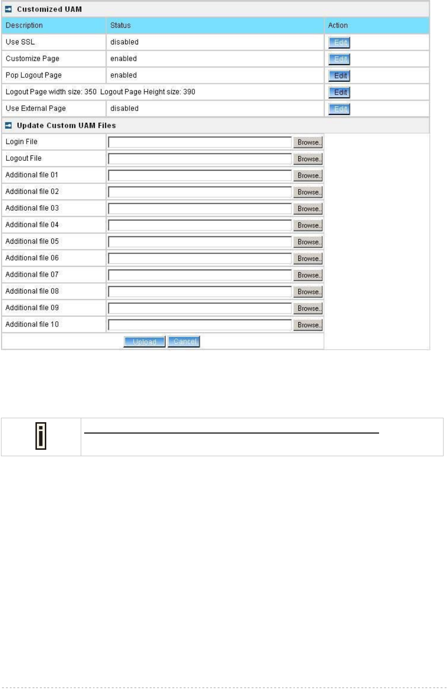
BW1254 User Guide v1.0 Nov. 2013
Page 171 of 184
Figure 308 – upload files
Enter the physical path and filename of the coffee template files, or click the “browse” button to
search the coffee template files are located.
The first two items are for login.html and logout.html files only. Additional
files are for CSS and image files, such as jpg, gif, png and etc.
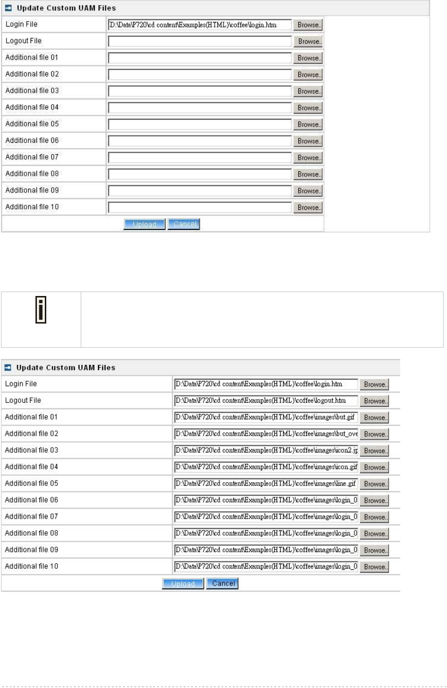
BW1254 User Guide v1.0 Nov. 2013
Page 172 of 184
Figure 309 – upload login.html
After entering all the template files, press upload button to start the uploading files to BW1254.
Only ten Additional files can be uploaded at one time. To upload more additional
file, repeat the same upload process in step 2-4, but please be aware of the first
two items are only for login.html and logout.html files. Image files can only be
uploaded to Additional file fields
Figure 310 – upload other files
Once all files are uploaded successfully, a list of Uploaded File List will show.
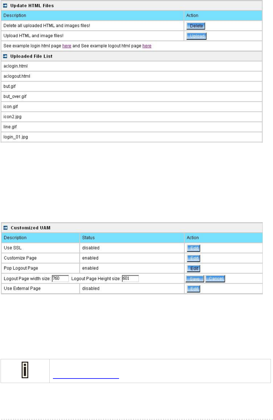
BW1254 User Guide v1.0 Nov. 2013
Page 173 of 184
Figure 311 – files have been uploaded
Verify if all files are uploaded successfully
Step2. Configure the pixels of logout window.
The README file in each template directory contains the information of the pixels settings for the
logout page. Enter the width size and height size setting of logout page and press the Save button.
E.g. the coffee bar template, the suggested size of logout page is 760 x 601.
Figure 312 – set the pixels of logout window
Step3. Everything is ready
Now, any users that access the internet via the BW1254 will see the new personalized login and
logout pages.
Let’s look at the new appearance of login and logout page based on the coffee bar template.
Make sure your computer is in the same network with BW1254 and enter
https://device IP address for the customized page test.
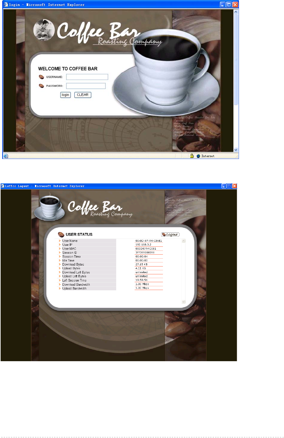
BW1254 User Guide v1.0 Nov. 2013
Page 174 of 184
:
Figure 313 – example of coffee bar login page
Figure 314 – example of coffee bar logout page

BW1254 User Guide v1.0 Nov. 2013
Page 175 of 184
FAQ
1. Question: How to add some links that could be accessed without authentication?
Answer: These authentication-free sites for users are so called “walled garden” area. Please
refer to the user’s guide to do the relating settings.
2. Question: How to hide the user login session information from my customers?
Answer: You can find these set of html code in logout.html we provided:
<td width="265" valign="top"><iframe src="logout.user?cmd=status" width="250"
height="240" marginwidth="0" marginheight="0" scrolling="yes"
frameborder="0"></iframe></td>
These set of code uses an embedded window to show the session data in logout window.
Comment them with HTML comments language “<!--“ and “//-->” will hide the session data in
logout window.
3. Question: If I don’t want the logout window to pop-up to users, how could I do?
Answer: Please login BW1254 and go to User | Customized UAM to disable “pop logout page.”
4. Question: If I close the logout window, how can I logout?
Answer: 1. just un-plug your wireless card, or un-plug your network cable if you use a wired card.
2. Open a browser window, and input the URL: “logout.usr”, then you will be redirect to
logout window.

BW1254 User Guide v1.0 Nov. 2013
Page 176 of 184
A) Specification
Wireless
Standard IEEE 802.11a/b/g/n
Data Rate
802.11n :
300,270,240,200.180,150,120,100,54,48,36,24,18,12,11,9,6,5.5,2,1Mbps
802.11a : 54,48,36,24,18,12,9,6Mbps
802.11g : 54,48,36,24,18,12,9,6Mbps
802.11b : 11,5.5,2,1Mbps (auto fallback)
Transmit Power
(adjustable RF power)
Max. 27 dBm ± 2dBm
(Maximum power will vary by channel, rate and regulatory domain)
Antennas 4 Dual-band Dipole Antennas with RP-SMA plug connector
Encryption WPA/WPA2(TKIP and CCMP-AES), Dynamic/static 64bits and 128bits
WEP
DynamicBridge Up to 31 bridge links
Interface
LAN 10/100/100Mb Ethernet, auto sensing, RJ-45
Console 1 for RJ-45 interface
Management
Interfaces HTTPs, Secure Telnet(SSHv2), SNMP
Software Update Remote software update via HTTPs
Reset H/W and S/W restore factory default
Physical Specification
Dimension 195 mm x 165 mm x 35 mm
Weight 790±10g
Environment Specification
Temperature Humidity
Operating 0 to +50°C 95%, non-condensing
Power Supply
POE IEEE802.3at, IEEE802.3af-2003 compliance
Power adaptor External power supply, input: 100-240 VAC, 50-60Hz and output: 48VDC
LEDs
4 LEDs Power, MODE, Ethernet, WLAN1, WLAN2
Warranty
1 years
Package Contents
BW1254 Indoor Access Point Ethernet patch cable
Screw Bag 4xAntennas
power supply(48VDC)
Appendix

BW1254 User Guide v1.0 Nov. 2013
Page 177 of 184
Related Products
Controllers: BG-6020G/G-4200 Public Access Controller
Access Points: BW1253 single radio 802.11a/b/g/n
hotspot indoor access point BW2251 dual radio 802.11a/b/g/n
hotspot outdoor access point
B) Factory Defaults for the BW1254
Network Interface Configuration Settings
Operation Mode
Mode AP
Network | Interface
AP Mode (Default)
Interface br0
Type LAN
IP Address 192.168.2.2
Netmask 255.255.255.0
Gateway 0.0.0.0
AP Router Mode
Interface eth0
Type WAN
IP Address 192.168.2.2
Netmask 255.255.255.0
Gateway 192.168.2.1
Network | RADIUS Properties
RADIUS Retries 5
RADIUS Timeout 2
NAS Server ID -
User Session Timeout 72000
User Accounting Update Interval 600
User Accounting Update Retry 60
User Idle Timeout 900
Bandwidth Up 512 Kbits
Bandwidth Down 512 Kbits
Network | RADIUS Servers
Name DEFAULT (default)
Type Authentication
IP Address 0.0.0.0
Port 1812
Secret password (case sensitive)
Type Accounting
IP Address 0.0.0.0

BW1254 User Guide v1.0 Nov. 2013
Page 178 of 184
Port 1813
Secret secret (case sensitive)
User Password Md5sum Secret disabled
Network | DHCP Server
DHCP Server
Status Disabled
IP Address from 192.168.3.2
IP Address to 192.168.3.254
Netmask 255.255.255.0
Gateway 192.168.3.1
WINS Address 0.0.0.0
Lease Time (seconds) 86400
DNS address 0.0.0.0
DNS Secondary address 0.0.0.0
Network | DNS (only for AP router mode)
Type Primary
IP Address 0.0.0.0
Type Secondary
IP Address 0.0.0.0
Network | Static Route (only for AP router mode)
No routes are defined on system.
WISP
No WISP defined on system.
Wireless | Basic
WLAN1
Regulatory Domain FCC
Channels 11(static)
Wireless Band 2.4GHz(11n HT20)
Total Output Power(EIRP) 14dBm
RTS Threshold 2347bytes
Layer2 Isolation disabled
Operation Mode AP
WLAN2
Regulatory Domain FCC
Channels 36(static)
Wireless Band 5GHz(11n HT20)
Total Output Power(EIRP) 13dBm
RTS Threshold 2347bytes
Layer2 Isolation disabled
Operation Mode AP
Wireless | Advanced
WLAN1
SSID BW1254-11ng

BW1254 User Guide v1.0 Nov. 2013
Page 179 of 184
Hidden SSID Disabled
Security Disabled
WLAN2
SSID BW1254-11na
Hidden SSID Disabled
Security Disabled
Wireless | MSSID
No multiple BSSID entry
Wireless | WEP
Status Disabled
Key1 to Key4 aaaaa
Wireless |MAC ACL
ACL Policy Disabled
User Settings
User | Customized UAM (Only for AP router mode)
Use SSL Disabled
Customize Page Disabled
User | Station Supervision
Interval 20
Failure count 3
User | WISP(Only for AP router mode)
Domain Policy Username@domain
No WISP defined on system
System Settings
System | Administrator
Super administrator: Username: admin (case sensitive)
Password: admin01 (case sensitive)
System | SNMP
SNMP Service Enabled
Readonly Community public
Readwrite Community private
Default Trap Community public
There are no SNMP traps on system.
System | Telnet
Telnet Service Enabled
SSH Service Enabled

BW1254 User Guide v1.0 Nov. 2013
Page 180 of 184
System | NTP
NTP Service Disabled
Time Zone GMT-12:00
There are no NTP Server settings on system.
System | Time
Date 1970/01/01
System | System Log
Remote Log Status Disabled
Host IP 192.168.2.1
Log Level info
Local Log Status Enabled
Log Limit(bytes) 102400
Log Level info
C) Location ID and ISO Country Codes
This list states the country names (official short names in English) in alphabetical order as given in
ISO 3166-1 and the corresponding ISO 3166-1-alpha-2 code elements.
It lists 239 official short names and code elements.
Location
ID Country Location
ID Country
AF Afghanistan LI Liechtenstein
AL Albania LT Lithuania
DZ Algeria LU Luxembourg
AS American Samoa MO Macao
AD Andorra MK Macedonia, the former Yugoslav
republic of
AO Angola MG Madagascar
AI Anguilla MW Malawi
AQ Antarctica MY Malaysia
AG Antigua and Barbuda MV Maldives
AR Argentina ML Mali
AM Armenia MT Malta
AW Aruba MH Marshall islands
AU Australia MQ Martinique
AT Austria MR Mauritania
AZ Azerbaijan MU Mauritius
BS Bahamas YT Mayotte
BH Bahrain MX Mexico

BW1254 User Guide v1.0 Nov. 2013
Page 181 of 184
BD Bangladesh FM Micronesia, federated states of
BB Barbados MD Moldova, republic of
BY Belarus MC Monaco
BE Belgium MN Mongolia
BZ Belize MS Montserrat
BJ Benin MA Morocco
BM Bermuda MZ Mozambique
BT Bhutan MM Myanmar
BO Bolivia NA Namibia
BA Bosnia and Herzegovina NR Nauru
BW Botswana NP Nepal
BV Bouvet island NL Netherlands
BR Brazil AN Netherlands Antilles
IO British Indian ocean territory NC New Caledonia
BN Brunei Darussalam NZ New Zealand
BG Bulgaria NI Nicaragua
BF Burkina Faso NE Niger
BI Burundi NG Nigeria
KH Cambodia NU Niue
CM Cameroon NF Norfolk island
CA Canada MP Northern Mariana islands
CV Cape Verde NO Norway
KY Cayman islands OM Oman
CF Central African republic PK Pakistan
TD Chad PW Palau
CL Chile PS Palestinian territory, occupied
CN China PA Panama
CX Christmas island PG Papua new guinea
CC Cocos (keeling) islands PY Paraguay
CO Colombia PE Peru
KM Comoros PH Philippines
CG Congo PN Pitcairn
CD Congo, the democratic republic of the PL Poland
CK Cook islands PT Portugal
CR Costa Rica PR Puerto Rico
CI Côte d'ivoire QA Qatar
HR Croatia RE Réunion
CU Cuba RO Romania
CY Cyprus RU Russian federation
CZ Czech republic RW Rwanda
DK Denmark SH Saint Helena

BW1254 User Guide v1.0 Nov. 2013
Page 182 of 184
DJ Djibouti KN Saint Kitts and Nevis
DM Dominica LC Saint Lucia
DO Dominican republic PM Saint Pierre and Miquelon
EC Ecuador VC Saint Vincent and the grenadines
EG Egypt WS Samoa
SV El Salvador SM San Marino
GQ Equatorial guinea ST Sao tome and Principe
ER Eritrea SA Saudi Arabia
EE Estonia SN Senegal
ET Ethiopia SC Seychelles
FK Falkland islands (malvinas) SL Sierra Leone
FO Faroe islands SG Singapore
FJ Fiji SK Slovakia
FI Finland SI Slovenia
FR France SB Solomon islands
GF French Guiana SO Somalia
PF French Polynesia ZA South Africa
TF French southern territories GS South Georgia and the south
sandwich islands
GA Gabon ES Spain
GM Gambia LK Sri Lanka
GE Georgia SD Sudan
DE Germany SR Suriname
GH Ghana SJ Svalbard and Jan Mayan
GI Gibraltar SZ Swaziland
GR Greece SE Sweden
GL Greenland CH Switzerland
GD Grenada SY Syrian Arab republic
GP Guadeloupe TW Taiwan, province of china
GU Guam TJ Tajikistan
GT Guatemala TZ Tanzania, united republic of
GN Guinea TH Thailand
GW Guinea-Bissau TL Timor-leste
GY Guyana TG Togo
HT Haiti TK Tokelau
HM Heard island and McDonald islands TO Tonga
VA Holy see (Vatican city state) TT Trinidad and Tobago
HN Honduras TN Tunisia
HK Hong Kong TR Turkey
HU Hungary TM Turkmenistan
IS Iceland TC Turks and Caicos islands
IN India TV Tuvalu

BW1254 User Guide v1.0 Nov. 2013
Page 183 of 184
ID Indonesia UG Uganda
IR Iran, Islamic republic of UA Ukraine
IQ Iraq AE United Arab emirates
IE Ireland GB United kingdom
IL Israel US United states
IT Italy UM United states minor outlying islands
JM Jamaica UY Uruguay
JP Japan UZ Uzbekistan
JO Jordan VU Vanuatu
KZ Kazakhstan Vatican city state see holy see
KE Kenya VE Venezuela
KI Kiribati VN Viet nam
KP Korea, democratic people's republic
of VG Virgin islands, British
KR Korea, republic of VI Virgin islands, u.s.
KW Kuwait WF Wallis and Futuna
KG Kyrgyzstan EH Western Sahara
LA Lao people's democratic republic YE Yemen
LV Latvia YU Yugoslavia
LB Lebanon Zaire see Congo, the democratic
republic of the
LS Lesotho ZM Zambia
LR Liberia ZW Zimbabwe
LY Libyan Arab Jamahiriya